JP2004157960A - Method of transferring print data, print system, and printer device - Google Patents
Method of transferring print data, print system, and printer device Download PDFInfo
- Publication number
- JP2004157960A JP2004157960A JP2003015048A JP2003015048A JP2004157960A JP 2004157960 A JP2004157960 A JP 2004157960A JP 2003015048 A JP2003015048 A JP 2003015048A JP 2003015048 A JP2003015048 A JP 2003015048A JP 2004157960 A JP2004157960 A JP 2004157960A
- Authority
- JP
- Japan
- Prior art keywords
- print data
- supply device
- printer
- request
- Prior art date
- Legal status (The legal status is an assumption and is not a legal conclusion. Google has not performed a legal analysis and makes no representation as to the accuracy of the status listed.)
- Withdrawn
Links
Images


Landscapes
- Accessory Devices And Overall Control Thereof (AREA)
- Record Information Processing For Printing (AREA)
Abstract
Description
【0001】
【発明の属する技術分野】
本発明は、プリンタ装置に印刷データを転送する方法に関し、特に、プリンタ装置が印刷データの供給元に対して印刷データの供給を要求するプル型の印刷方法に関する。
【0002】
【従来の技術】
デジタルカメラやデジタル放送受信機(STB;Set Top Box)等のAV(Audio Visual)機器にプリンタ装置を接続し、AV機器で撮像・受信された映像をプリンタ装置に直接印刷することが試みられている。ところが、STB等のAV機器は、パーソナルコンピュータと異なり、一般に、ハードディスク装置やCD−ROMドライブ装置等の大容量補助記憶装置を備えておらず、また自身のファームウェアを更新する機能を持つ機器も少ないので、接続するプリンタ装置の機種ごとに異なるドライバソフトウェアをインストールするという事態は回避されることが好ましい。したがって、一定の規格に準拠している機器であれば機器固有のソフトウェアをインストールすることなく、自由に選択したAV機器とプリンタ装置とを接続し、印刷が可能となるような柔軟な接続方式が望まれる。
【0003】
このような要望に応える策の一つとして、IEEE1394規格で規定されたAV/Cプロトコルがある(例えば、非特許文献1参照)。AV/Cプロトコルは、AV機器の接続に関し、必要最小限の標準プロトコルを決定し、互換性を保ち、各メーカーが個別に機器の性能を高めることができる枠組みを提供している。なお、上記AV/Cプロトコルの中で、特にプリンタ装置に関するAV/Cコマンドを取り決めたものとしてAV/C Printer Subunitがある。
【0004】
図40は、既存のAV/C Printer Subunitに従ってデジタルカメラ等のAV機器がプリンタ装置に画像を印刷出力するときの通信手順の一例を示すシーケンス図である。ここでは、IEEE1394バスで接続されたコントローラ900が内部に保持する画像等の印刷オブジェクトをプリンタユニット(プリンタ装置)910に出力する場合の通信シーケンスとそのときのコマンド及びレスポンスが示されている。
【0005】
まず、コントローラ900は、プリンタユニット910からバージョン情報を取得し、プリンタユニット910にジョブ識別子job_IDを指定してプリントジョブを生成した後に、論理的な転送チャネル(非同期データ転送用コネクション;Asynchronous Connection)を確立する。
【0006】
そして、コントローラ900は、AV/CコマンドCAPTUREをプリンタユニット910に送ることで、出力したい印刷オブジェクトを指定するとともに、その印刷オブジェクトを受け取るように指示した後に、上記転送チャネルを介して、指定した印刷オブジェクトをプリンタユニット910に出力(push)する。
【0007】
印刷が完了し、プリンタユニット910からコントローラ900に終了状態ACCEPTED responseが返されると、コントローラ900は、上記転送チャネルAsynchronous Connectionを切断し、プリントジョブをクローズした後に、プリンタユニット910におけるジョブの状態をポーリングする。
【0008】
このようにして、AV/C Printer Subunitに従ってAV機器が印刷オブジェクトをプリンタ装置に出力することで、プリンタ装置個別のドライバソフトをインストールすることなく、印刷出力が可能となる。
【0009】
【非特許文献1】
IEEE Std 1394−1995, Standard for a High Performance Serial Bus
【0010】
【発明が解決しようとする課題】
しかしながら、上記AV/C Printer Subunitにおける印刷コマンドCAPTUREは、そのコマンドの発行に続いて、そのコマンドを発行したコントローラが自ら保有する印刷オブジェクトをプリンタ装置に出力するプッシュ型の印刷形態(Push Print)を前提としており、プリンタ装置自ら必要な印刷オブジェクトを必要な場所から取り出す(プリンタ装置からのデータ取得要求に基づいて印刷を実行する)というプル型の印刷形態(Pull Print)に対応していないという第1の課題がある。
【0011】
また、HTMLなどで記載されたドキュメントでは、内部で他の印刷オブジェクトへのリンク(リンクパス情報)が記述されている。このリンクパス情報は、絶対パス(ファイルの位置を一意的に示す)だけでなく、相対パス(ある基準点からの相対位置によってファイルの位置を示す)で表現される可能性がある。そのために、リンクパス情報が、相対パスである場合には、絶対パスと同様な方法を用いては、印刷対象のファイルを取得することができないという第2の課題がある。
【0012】
さらに、IEEE1394規格においては、印刷データ供給装置のアドレスに関して、IEEE1394規格固有のバスリセットの影響が生じる。つまり、バスリセットは、IEEE1394ネットワーク上の機器の電源on/off、ケーブルの挿抜毎に発生するため、アドレスが再設定(変更)された場合に、正しいデータが取得できないおそれがあるという第3の課題がある。
【0013】
そこで、本発明は、このような状況に鑑みてなされたものであり、プル型のプリンタ装置が持っている機能を有効に発揮させることが可能な印刷データ転送方法等を提供することを第1の目的とする。
【0014】
また、リンクパス情報が相対パスである場合にも、ファイルを取得することができる印刷ファイル取得システム等を提供することを第2の目的とする。
さらに、バスリセット時においても、正しいデータを取得することができるデータ転送システム等を提供することを第3の目的とする。
【0015】
【課題を解決するための手段】
上記第1の目的を達成するために、伝送路で接続された印刷データ供給装置とプリンタ装置間に印刷データを転送するための方法であって、前記印刷データ供給装置が保持する印刷データを印刷させるため、前記印刷データ供給装置の属性情報を伴って前記プリンタ装置に対して印刷要求する段階と、前記要求に応じ、前記プリンタ装置が前記属性情報に基づいて前記印刷データ供給装置にデータ要求する段階と、前記データ要求に応じ、前記印刷データ供給装置が印刷データを前記プリンタ装置に送信する段階とを有する。
【0016】
ここで、前記プリンタ装置は、前記属性情報として印刷対象データへのリンクパス情報を受信し、印刷対象データ本体と印刷対象データに記載されたリンクパス情報で特定される印刷データとを前記印刷データ供給装置に対して要求してもよいし、例えば、XHTML−Print形式等で記述された、印刷対象データへのリンクパス情報が記載されたリンクファイルを受信し、前記印刷データ供給装置に対し、前記受信したリンクファイルに記載されたリンクパス情報で特定される印刷データを要求してもよい。
【0017】
より具体的に、IEEE1394に適合させて言うならば、AV/Cプリンタコマンドのキャプチャコマンドを受信したプリンタ装置は、印刷対象データや印刷対象データからリンクされたJPEGやPNG、テキストなどのデータを取得するために、AV/Cコマンドを発行し、既に確立されているコネクションを経由してデータを受信する。
【0018】
なお、前記属性情報で指定されたリンクパス情報または前記印刷対象データ内に記載されたリンクパス情報がある基準点からの位置を示す相対パスである場合、前記属性情報に、さらに前記リンクパス情報の基準位置を指定してもよい。また、前記印刷対象データ内に記載されたリンクパス情報の基準位置は、前記印刷要求における属性情報で指定された印刷対象データのリンクパス情報から抽出してもよい。また、前記プリンタ装置はこれらの基準位置を前記印刷要求に対する完了通知を送信するまで保持してもよい。
【0019】
また、前記データ要求と前記送信とを繰り返してもよい。さらに、前記コネクションは、プリンタ装置によって確立されたものであってもよいし、前記印刷データ供給装置及び前記プリンタ装置以外の印刷制御装置によって確立されたものであってもよい。
【0020】
また、前記属性情報が、前記印刷データ供給装置を特定するためのアドレス情報であってもよい。具体的には、前記アドレス情報はIEEE1394 AV/C規格におけるNode_ID又はEUI_64であってもよいし、IEEE1394 AV/C規格におけるNode_ID又はEUI_64に、Subunit_typeとSubunit_IDとを組み合わせたものであってもよい。
【0021】
また、前記属性情報が、前記コネクションにおける印刷データ供給装置側の入力ポートを特定するコネクション情報であってもよい。具体的には、前記コネクション情報はIEEE1394 AV/C規格におけるsubunit_plug_idであってもよい。
【0022】
また、前記属性情報が、前記印刷データ供給装置の種類を特定するタイプ情報であってもよい。具体的には、前記タイプ情報はIEEE1394 AV/C規格におけるSubunit_Typeであってもよい。
【0023】
また、前記プリンタ装置は、前記印刷データ供給装置以外の印刷制御装置から前記印刷要求を受信してもよいし、前記要求された印刷に必要なデータ受信が完了した後に前記印刷要求に対する完了通知を送信してもよい。
【0024】
また、前記印刷要求には、前記印刷データ供給装置と関連しない第1パラメータ群と前記印刷データ供給装置に関連する第2パラメータ群とが含まれていてもよい。このとき、前記印刷要求は、前記第1パラメータ群と前記第2パラメータ群とを含む一つの命令であってもよいし、前記印刷要求は、前記第1パラメータ群を含む第1命令と、前記第2パラメータ群を含む第2命令とに分離されていてもよい。
【0025】
また、前記伝送路におけるアドレスが再設定された場合に、前記印刷データ供給装置と前記プリンタ装置の間のコネクションを復旧し、次に、前記プリンタ装置に対する印刷要求を再送し、前記再送要求に対し、前記プリンタ装置は、要求された印刷に必要なデータ受信を再開してもよい。ここで、前記再送要求は、バスリセット後の印刷データ供給装置のアドレス情報に基づくものであってもよい。
【0026】
また、前記印刷データ供給装置に対し、前記リンクパス情報の基準位置を設定しても良い。なお、前記印刷データ供給装置に対する基準位置の設定はコネクション毎に設定しても良い。
【0027】
また、前記プリンタ装置は、前記印刷データ供給装置から取得した印刷オブジェクトに、他の印刷オブジェクトへの参照を示すリンク情報が含まれているときには、参照先の印刷オブジェクトを印刷するタイミングになったときに、前記印刷データ供給装置に対して前記リンク情報が示す参照先の印刷オブジェクトの送信を要求することにより、当該参照先の印刷オブジェクトを取得し、取得した印刷オブジェクトを印刷してもよい。
【0028】
また、前記印刷データ供給装置は、前記基準位置が変更された旨を前記印刷データの要求に対するレスポンスで通知してもよいし、前記印刷データ供給装置は、着脱可能な記録媒体を備え、前記記録媒体の装着があった旨を示すパラメータを用いて、前記基準位置が変更された旨を通知してもよい。なお、前記プリンタ装置に対する印刷要求前に、前記印刷データ供給装置に対して前記リンクパス情報の基準位置を設定し、前記印刷要求に対する完了通知を受信するまで前記基準位置の設定を変更しないのが好ましい。
【0029】
なお、前記属性情報には、印刷データ供給装置が保管する印刷データのうち、印刷の対象となる第1印刷データの格納位置を絶対パスで指定する第1リンクパス情報と、前記第1印刷データによって参照される第2印刷データの前記基準位置とが含まれてもよい。
【0030】
また、前記印刷データ転送方法は、さらに、前記印刷要求に先立ち、前記伝送路上に、印刷データを保持する印刷データ供給装置と印刷データを印刷するプリンタ装置が接続されているか否かを確認し、前記印刷データ供給装置及び前記プリンタ装置の少なくとも一方が接続されていない場合には、エラーである旨をユーザに通知するステップを含むのが好ましい。
【0031】
また、前記プリンタ装置に対する印刷要求では、前記印刷データ供給装置に印刷データを要求する機能を前記プリンタ装置が有するか否かの問い合わせが含まれ、前記印刷データ転送方法は、さらに、前記プリンタ装置が前記問い合わせに対して返答するステップを含んでもよい。ここで、前記プリンタ装置が、前記問い合わせに対して前記機能を有していない旨の返答をした場合には、前記印刷データ供給装置は、前記プリンタ装置からの印刷データの要求を受けることなく、印刷データを前記プリンタ装置に送信してもよい。また、前記印刷データ転送方法は、さらに、前記プリンタ装置が、前記問い合わせに対して前記機能を有していない旨の返答をし、かつ、印刷の対象となる印刷データが上記機能を有するプリンタ装置のみによって印刷可能な場合に、エラーである旨をユーザに通知するステップを含んでもよい。
【0032】
なお、本発明は、このような印刷データ転送方法として実現することができるだけでなく、これらの印刷データ転送方法を実行する印刷制御装置、印刷データ供給装置及びプリンタ装置からなる印刷システムとして実現したり、それらの装置単体として実現したり、その特徴的な動作をパーソナルコンピュータ等の汎用のコンピュータに実行させて機能させるプログラムとして実現することもできる。そして、そのプログラムは、CD−ROM等のコンピュータ読み取り可能な記録媒体やインターネット等の伝送媒体を介して頒布することができるのは言うまでもない。
【0033】
また、上記第2の目的を達成するために、本発明の印刷ファイルの取得システムは、印刷ファイルの格納位置を指定するリンクパス情報を保管する保管手段と、前記保管手段から取得したリンクパス情報の一部又は全てが、所定の基準点からの相対的な位置を示す相対パスである場合に、前記所定の基準点を示す基準位置データに基づき、前記相対パスを、印刷ファイルの絶対的な位置を示す絶対パスに変換する変換手段と、前記変換手段により変換された絶対パスから特定可能な印刷ファイルを取得する取得手段と、を有する。
【0034】
さらに、上記第3の目的を達成するために、本発明の印刷データの転送システムは、伝送路で接続された印刷データ供給装置とプリンタ装置とを備え、前記印刷データ供給装置から前記プリンタ装置に対して印刷データを転送する印刷データ転送システムであって、バスリセット後、前記印刷データ供給装置と前記プリンタ装置との接続を復旧し印刷データ転送を再開する場合に、バスリセット後の前記印刷データ供給装置および前記プリンタ装置のネットワーク接続情報を取得するネットワーク情報取得手段と、前記ネットワーク情報取得手段から得られたネットワーク接続情報に基づいて印刷データ供給装置とプリンタ装置との間のデータ転送コネクションを復旧するコネクション復旧手段と、前記ネットワーク情報取得手段から得られたネットワーク接続情報に基づいて印刷要求を再送する印刷要求再送手段と、前記印刷要求再送手段により再送された印刷要求に基づき、印刷オブジェクトを取得する取得手段と、を有する。
【0035】
【発明の実施の形態】
以下、本発明の実施の形態について図面を用いて詳細に説明する。
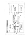
図1は、本実施の形態における印刷システムのシステムモデルを示す図である。このシステムモデルは、IEEE1394バスで接続されたコントローラ11とHDDユニット12とプリンタユニット13とから構成され、IEEE1394で規定される従来のシステムモデルと基本的な構成は同一であるが、プル型プリンタ装置に固有の動作(HDDユニット12とプリンタユニット13間のやりとり)が追加されている点に特徴を有する。
【0036】
コントローラ11は、IEEE1394バス上でコネクション管理機能を実装したSTB等の機器である。HDDユニット12は、ハードディスクドライブ装置(Hard Disk Drive)等のバス上でのデータ送信機器(Producer)であり、送信データを保有するストレージサブユニット12aを有している。プリンタユニット13は、プリンタ装置等のバス上でのデータ受信機器(Consumer)であり、受信データを印刷するプリンタサブユニット13aを有する。
【0037】
なお、ユニットはAV機器に対応し、サブユニットはAV機器の機能を司るもの(仮想的な機能単位)である。サブユニットの組み合わせがユニットとなり、ユニットの中をどのような機能単位で分けるかは適宜決定される。また、サブユニットは、バーチャルな機能単位であり、必ずしもハードウェア構成と一致するものではない。
【0038】
本図における特徴は、HDDユニット12とプリンタユニット13間のやりとり(コマンド及びレスポンス)に示されているように、コントローラ11等がプリンタユニット13に印刷オブジェクトをプッシュして印刷させるだけでなく、プリンタユニット13がHDDユニット12から印刷オブジェクトをプルして印刷し得る点である。
【0039】
なお、印刷オブジェクトは、既に確立されている非同期データ転送用のコネクション(Asynchronous Connection)経由で伝送される。IEEE1394 AV/C規格におけるコントローラ−サブユニットモデルとして説明すると、コントローラ11はプリンタユニット13内のプリンタサブユニット13aに対するコントローラである。また既存のプッシュ型のプリントのようにコントローラ11の指示で、HDDユニット12からプリンタユニット13に印刷オブジェクトをプッシュする場合は、コントローラ11はHDDユニット12内のストレージサブユニット12aに対するコントローラとなる。また、本実施の形態で実現可能なプル型のプリントのように、印刷処理中にプリンタユニット13がHDDユニット12から印刷オブジェクトをプルする場合は、プリンタユニット13がHDDユニット12内のストレージサブユニット12aに対するコントローラとなる。この際、プリンタサブユニット13a、またはプリンタサブユニット13aとは別のモジュールが内部的にコントローラの役目を果たす。
【0040】
図2は、図1に示されたシステムモデルにおける通信シーケンスを示す図であり、従来技術における図40に対応する。図40と異なる点は、フェーズobject pushにおけるやりとりである。本図のシーケンスにおいては、図40のシーケンスで使用されたコマンドCAPTUREに代えて、コマンドCAPTURE REFがコントローラ11からプリンタユニット13に発せられ、そのコマンドのパラメータに従って、プッシュ型又はプル型による印刷オブジェクトの転送及び印刷が実行される点が図40のシーケンスと異なっている。
【0041】
なお、コマンドCAPTURE REFは、従来のコマンドCAPTUREの機能を踏襲しつつ、プル型印刷を可能にするための機能を追加した、コマンドCAPTUREの拡張コマンドに相当する。このコマンドCAPTURE REFは、このコマンドを発行した装置とは異なる装置(ユニット、サブユニット)に置かれている印刷オブジェクトへの参照(印刷オブジェクトの所在を示すパラメータ。リンクパス情報のこと)を含んでいるので、このコマンドを受けたプリンタユニット13による印刷オブジェクトのプル動作が可能となる。つまり、コントローラ11が、コントローラ11とは別の機器であるプリンタユニット13に対し、コントローラ11及びプリンタユニット13とは別の機器であるHDDユニット12上のデータを印刷するよう指示することが可能となる。
【0042】
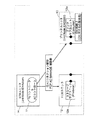
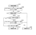
具体的には、図2のフェーズobject pushにおいて、図3に示される通信シーケンスが行われる。まず、コントローラ11がプリンタユニット13にコマンドCAPTURE REFを発行すると(ステップS10)、プリンタユニット13はレスポンスINTERIM responseを返す(ステップS11)。続いて、プリンタユニット13は、HDDユニット12に対してファイル送信要求コマンド等を発行することで、印刷オブジェクトの先頭あるいは主要な構成オブジェクトであるメインオブジェクト(例えば、HTMLファイル)の送信を要求する(ステップS12)。これによって、メインオブジェクトは、既に確立されているコネクションasynchronous connection経由で、HDDユニット12からプリンタユニット13に転送される(ステップS13)。
【0043】
プリンタユニット13は印刷メインオブジェクトの印刷処理を行い、印刷処理中にリンクパス情報を抽出した場合など、必要に応じて、HDDユニット12に対してファイル送信要求コマンドを発行することで、メインオブジェクトに記述されている参照オブジェクト(ハイパーリンクが張られた参照先の画像オブジェクト等)の送信を要求する(ステップS14)。これによって、参照オブジェクトは、上記コネクション経由で、HDDユニット12からプリンタユニット13に転送される(ステップS15)。
【0044】
このようなメインオブジェクトや参照オブジェクトの転送シーケンスを必要回数だけ繰り返すことによって全ての印刷オブジェクトの取得を完了すると、プリンタユニット13は、コントローラ11に対して、コマンドCAPTURE REFに対するレスポンスACCEPTEDを返信する(ステップS16)。これによって、プル型の印刷コマンドCAPTURE REFに対する実行が完了する。
【0045】
なお、コマンドCAPTURE REFに対する応答レスポンスACCEPTEDの返信は、印刷処理を進めるにあたって印刷ジョブを構成するデータ(印刷メインオブジェクト及び参照オブジェクト)の受信が不要になった段階をもって行うことで、一度 CAPTURE REFに対するレスポンスを受信したことを契機として切断したコネクションを、印刷中の紙づまり等による再処理のために再度コネクションを確立するといった手間を回避することができる。具体的には、プリンタユニット13の実装が、印刷ジョブを構成する全てのデータを受信し、プリンタユニット13内に格納した後に実際の印刷処理を行う実装である場合は、印刷ジョブを構成する全てのデータを受信完了した時点でコマンドCAPTURE REFに対する応答レスポンスACCEPTEDの返信を行う。一方、プリンタユニット13の実装が、コマンドCAPTURE REF受信後印刷メインオブジェクトから順次印刷処理していく実装であり、該当データが必要になる度にその都度受信する実装である場合は、印刷ジョブの印刷が完了した時点でコマンドCAPTURE REFに対する応答レスポンスACCEPTEDの返信を行う。
【0046】
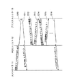
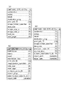
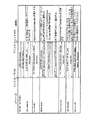
図4は、コマンドCAPTURE REFの詳細な命令フォーマットを従来のコマンドCAPTUREと比較しながら説明するための図であり、図4(a)は、プッシュ型プリントを前提とする従来のコマンドCAPTURE、図4(b)は、プッシュ型及びプル型プリントが可能であり、図4(c)はプル型プリントのみが可能な本発明に係るコマンドCAPTURE REFのAV/Cコマンドフレームを示す。なお、ここでは、両コマンドのAV/Cコマンドフレームにおけるオペランド(命令に付加されるパラメータ)とその長さ(バイト数)が示されている。また、図4(b)及び(c)におけるコマンドフレームはあくまでも例であり、図4(b)に示されたコマンドフレームと図4(c)に示されたコマンドフレームとをマージしても構わないし、パラメータの並びがどのような順番でも構わないことは言うまでもない。
【0047】
図4(a)に示されるように、プッシュ型プリントを前提とする従来のコマンドCAPTUREは、オペランドとして、具体的な動作を指定するパラメータsubfunction、返信用のパラメータstatus及びresult、コネクションにおけるプリンタユニット(データ受信機器;consumer)側の入力ポートを指定するパラメータdestination_plug、命令の対象となるプリントジョブを指定するパラメータprint_job_ID、JPEGやGIF等の印刷オブジェクトのフォーマットを指定するパラメータimage_format_specifier、転送する印刷オブジェクトのデータサイズを指定するパラメータdata_size、イメージデータとしてのピクセル数を指定するパラメータimage_size_x及びimage_size_y、Nin1印刷指定時のコマンド応答において、次に転送される印刷オブジェクトに関する情報がセットされるパラメータnext_pic及びnext_pageの指定が可能な構造となっている。
【0048】
これに対し、図4(b)に示されるように、本実施の形態におけるプッシュ型及びプル型プリントが可能なコマンドCAPTURE REFは、オペランドとして、従来のコマンドCAPTUREで用いられたパラメータsubfunction、status、result、destination_plug、print_job_ID、image_format_specifier、data_size、next_pageに加えて、5つの新たなパラメータproducer_node_ID、source_plug、subunit_type、subunit_id、object_pathが追加されている。
【0049】
パラメータproducer_node_IDは、プルすべき印刷オブジェクトが置かれている場所、つまり、HDDユニット等のデータ送信機器(producer)を指定するオペランドである。ここで、もし、この印刷コマンドを発するコントローラがデータ送信機器(producer)を兼ねている(印刷オブジェクトを保有している)場合には、このパラメータproducer_node_IDの値として自装置の値に設定しておくことで、自ら保有する印刷オブジェクトの印刷を可能としてもよい。
【0050】
また、パラメータsource_plugは、コネクションにおけるデータ送信機器(producer)側の入力ポートを指定するオペランドである。このパラメータsource_plugは、コントローラ11がHDDユニット12とプリンタユニット13間のコネクションを確立したときに(図2のフェーズconnection)、取得したパラメータの1つである。
【0051】
また、パラメータsubunit_type及びsubunit_idは、データ送信機器(producer)のタイプ(例えば、DSC(DigitalStill Camera)/STB/DTV(Digital TV)/HDD等の区別)及びその装置番号を指定するオペランドである。データ送信機のタイプは、機器特性の差やバージョンの差に基づき、情報の授受に関するコマンドの体系や順序等が変わる場合に、その種別を識別するためのものである。
【0052】
また、パラメータobject_pathは、HDD等のデータ送信機器(producer)における階層化されたファイルシステムでの印刷オブジェクト(メインオブジェクト)の格納場所を示すオペランドである。具体的には印刷メインオブジェクトのリンクパス情報が格納される。
【0053】
また、同じくコマンド図4(c)に示す本実施の形態におけるプル型プリントのみが可能なコマンドCAPTURE REFでは、オペランドとして、従来のコマンドCAPTUREで用いられたパラメータsubfunction、status、result、destination_plug、print_job_ID、image_format_specifier、data_sizeに加えて、6つの新たなパラメータproducer_node_ID、source_plug、subunit_type、subunit_id、object_path、base_pathが追加されている。
【0054】
なお、図中に「疑問符(クエスチョンマーク)」が付いているdata_size、producer_node_ID、source_plug、subuinit_type、subunit_ID、base_pathに関しては、印刷要求を行う上で必須ではないが、存在すればプリンタユニット13における処理負荷が軽減するなどの利点を持つパラメータである。したがってコマンドフレームに存在しなくとも良いし、存在しても値を設定する必要のないパラメータである(詳しくは後述する)。以下、具体的にパラメータの内容を説明する。
【0055】
パラメータproducer_node_IDは、プルすべき印刷オブジェクトが置かれている場所、つまり、HDDユニット等のデータ送信機器(producer)のアドレスを指定するオペランドである。ここで、この印刷コマンドを発するコントローラがデータ送信機器(producer)を兼ねている(印刷オブジェクトを保有している)場合には、このパラメータproducer_node_IDの値として自装置の値を設定しておくことで、自ら保有する印刷オブジェクトの印刷が可能となる。
【0056】
また、パラメータsource_plugは、コネクションにおけるデータ送信機器(producer)側の入力ポートを指定するオペランドである。このパラメータsource_plugは、コントローラ11がHDDユニット12とプリンタユニット13間のコネクションを確立したときに(図2のフェーズconnection)、取得したパラメータの1つである。
【0057】
また、パラメータsubunit_type及びsubunit_idは、データ送信機器(producer)のタイプ(例えば、DSC(DigitalStill Camera)/STB/DTV(Digital TV)/HDD等の区別)及びその装置番号を指定するオペランドである。データ送信機のタイプは、機器特性の差やバージョンの差に基づき、情報の授受に関するコマンドの体系や順序等が変わる場合に、その種別を識別するためのものである。
【0058】
また、パラメータobject_pathは、HDD等のデータ送信機器(producer)における階層化されたファイルシステムでの印刷オブジェクト(メインオブジェクト)の格納場所を示すオペランドである。具体的には印刷メインオブジェクトのリンクパス情報が格納される。
【0059】
また、パラメータbase_pathは、詳しくは後述するが、相対パスの解決時に相対パスの基準位置として用いるものであり、プリンタユニットにおいて印刷メインオブジェクトから抽出した参照オブジェクトのリンクパス情報が相対パスであった場合、本パラメータを用いてリンクパス情報を絶対パスに変換するためのものである。後述するが、object_pathが相対パスである場合においても、同じく相対パスの基準位置として本パラメータを用い、object_pathを絶対パスに変換する。
【0060】
このような付加されたパラメータを参照することによって、このコマンドCAPTURE REFを受け取ったプリンタユニットは、コントローラとして、データ送信機器(producer)に対して、サブユニット及びデータパスを指定しながらメインオブジェクトや参照オブジェクト等の印刷オブジェクトを要求し取得することで、プル型のプリントを行うことができる。このとき、パラメータsubunit_typeで特定されるコマンド体系や順序に従って、データ送信機器と情報の授受を行う。
【0061】
なお、本図4(b)に示されたコマンドCAPTURE REFでは、従来のコマンドCAPTUREで用いられたパラメータの一部image_size_x、image_size_y及びnext_picが使用されていない。これは、図4(b)に示されたコマンドフォーマットは、HTMLファイル等のリンク情報を含むファイルを対象としているからである。
【0062】
なお、このようなファイルではなく、ラスターイメージデータを対象とする場合には、従来コマンドで用いられている全てのパラメータを含ませてもよい。また、本図4(c)に示されたコマンドCAPTURE REFでは、加えてnext_pageが使用されていない。これはコマンドフレームに含ませても構わないが必須ではないため省略したものである。
【0063】
また、上記コマンドCAPTURE REFは、参照オブジェクト(メインオブジェクトから参照されている印刷オブジェクト)がメインオブジェクトと同一のユニット及びサブユニット内に存在し、同一のコネクションパスで伝送できることが前提となっている。
【0064】
ここでリンクパス情報について説明する。
リンクパス情報は、前述のようにファイルの位置を一意に指定する情報のことであり、例えばローカルエリア上のファイル位置を指定するファイルパス(例:c:¥windows¥regedit.exe)や、インターネットなどのネットワーク上のファイル位置を指定するURL(Uniform Resource Locator 例:http://www.panasonic.co.jp/products/tv/index.html)などのことを指す。HTMLファイルなどでは、リンクパス情報が絶対パスと相対パスのどちらか一方で記述されている。
【0065】
絶対パスはその情報のみでデータの位置を一意に指定するが、相対パスは、ある基準位置から目的のデータまでの道筋を記述したものであり、基準位置との組み合わせることでデータの位置を一意に指定することができる。プル型のプリントを行う場合、リンクパス情報が全て絶対パスであれば特に問題はないが、リンクパス情報の一部または全てが相対パスである場合もあり得る。この場合は、プリンタユニット13またはHDDユニット12が何らかの手段によって相対パスを絶対パスに変換するパスの解決を行う必要がある。
【0066】
上記コマンドCAPTURE REFを受けたプリンタユニットがデータ送信機器(producer)に置かれたHTMLファイルをプルする場合におけるURL(Uniform Resource Locator)の解決は、以下の通りである。
(1)URLが相対パスで指定されている場合
URLが相対パスで指定されている場合には、以下に述べる3つの方法のいずれかによって最終的なURL(絶対パス)が解決される。
【0067】
まず、パスの解決をプリンタユニット13において行う第1の方法について説明する。
この方法は、図4(b)のようにコマンドフレームを簡略化するため、base_pathパラメータを省略したCAPTURE REFコマンドを採用した場合に最適である。後述する第2の方法に比べ文字列を操作する分プリンタユニット13の負荷は増えるが、第2の方法に比べCAPTURE REFコマンドフレームの長さを節約できる利点や、後述する第3の方法に比べパスの解決が印刷指示毎に独立しており確実にパスの解決を行えるという利点がある。具体的に説明すると、例えば、図4(b)のパラメータobject_path(A)が、”/tmp/1394ta.html”であり、メインオブジェクトから参照されている参照オブジェクトの指定(B)が、<image border=”0”src=”Images/Q4_plug.gif” width=”210” height=”42”>である場合には、最終的なファイルパスFile_path(=(A−メインオブジェクト名)+B)は、”/tmp/Images/Q4_plug.gif”と決定される。
【0068】
このようにパスの解決の第1の方法におけるポイントは、コントローラ11より受信したコマンドCAPTURE REFのパラメータobject_pathをもとに、プリンタユニット13が印刷メインオブジェクトの置かれている位置を導出し、この導出した位置を以後相対パスの基準位置として活用することで、パスの解決をプリンタユニット13が行う点である。
【0069】
次にパスの解決をプリンタユニット13において行う第2の方法について説明する。
この方法は、図4(c)のように、コマンドフレームに相対パスの基準位置であるbase_pathパラメータを追加したCAPTURE REFコマンドを採用する場合に限定されるが、前述の第1の方法に比べ処理が容易であり、第3の方法に比べパスの解決が印刷指示毎に独立しており確実にパスの解決を行えるという利点がある。具体的には、図4(c)のパラメータobject_path(A)が相対パスである場合、パラメータbase_pathで指定されている相対パスの基準位置を用いて相対パスを絶対パスに変換する。例えば、パラメータobject_pathが相対パス”./1394ta.html”であり、パラメータbase_pathが”c:/windows/”である場合は、base_path + object_pathから、最終的なファイルパスは”c:/windows/1394ta.html”となる。
【0070】
このようにして導出した絶対パスを用いて、ストレージサブユニット12aに印刷メインオブジェクトの送信要求を行う。同じく、印刷メインオブジェクトに記載されているリンクパス情報が相対パスであった場合にも、同様にパラメータbase_pathを用いてパスの解決を行う。例えば印刷メインオブジェクトに<image border=”0” src=”Images/Q4_plug.gif” width=”210” height=”42”>という記載がある場合には、リンクパス情報は”Image/Q4_plug.gif”であり、これは相対パスである。したがって base_path + ”Image/Q4_plug.gif”から、最終的なパスは、”c:/windows/Images/Q4_plug.gif”となる。
【0071】
このようにコマンドCAPTURE REFパラメータbase_pathは、印刷メインオブジェクト内に記載されたリンクパス情報が相対パスである度に、パスの解決に使用する。したがって、プリンタユニット13は、コマンドCAPTURE REFパラメータbase_pathを、当該コマンドで印刷指示された印刷ドキュメントのデータ受信が完了するまで保持する。
【0072】
このようにパスの解決の第2の方法におけるポイントは、コントローラ11が相対パスの基準位置をコマンドCAPTURE REFのパラメータbase_pathを用いてプリンタユニット13に通知しておくことで、この通知された基準位置を用いてパスの解決をプリンタユニット13が行う点である。なお、第2の方法において前述した例のようにobject_pathを相対パスとすることで、図4(c)に示したコマンドCAPTURE REFのコマンドフレームの長さを節約することができる。
【0073】
最後に、HDDユニット12においてパスの解決を行う第3の方法について述べる。
この方法は、コントローラ11がHDDユニット12に相対パスの基準位置としてカレントディレクトリ情報をあらかじめ設定しておく方法である。第1の方法に比べパスの解決をHDDユニット12で行うのでプリンタユニットの負荷を軽減でき、第2の方法に比べCAPTURE REFのコマンドフレームを節約できるという利点がある。具体的に説明すると、例えば図4(b)のパラメータobject_path(A)が、相対パス”./tmp/1394ta.html”であり、カレントディレクトリ情報(C)が”c:/windows/”であるとする。プリンタユニット13がobject_path(A)で特定できるHDDユニット12上のデータを受信する場合、前記第1、第2の方法とは異なりプリンタユニットにおいてパスの解決は行わず、そのまま相対パスである(A)を用いてHDDユニット12にデータの送信を要求する。この要求を受けるとHDDユニットはカレントディレクトリ情報を用いてパスの解決を行い、最終的なファイルパスを(C)+(A)である”c:/windows/tmp/1394.html”として導出し、該当するデータをプリンタユニット13へ送信する。
【0074】
このようにパスの解決の第3の方法におけるポイントは、コントローラ11が相対パスの基準位置をカレントディレクトリ情報としてHDDユニット12に設定しておくことで、この設定されたカレントディレクトリ情報を用いてパスの解決をHDDユニット12が行う点である。
【0075】
なお、カレントディレクトリ情報の設定方法は任意であるが、例えばコントローラ11とHDDユニット12が同一の機器である場合は、内部的に設定してもよいし、HDDユニット12のカレントディレクトリ情報を設定する新規コマンドを新設するなどしてもよい。カレントディレクトリ情報の設定の単位は任意であるが、HDDユニットに接続されたコネクション単位で設定してもよいし、機器全体として設定してもよい。特にHDDユニット12が複数のコネクションを同時に確立可能である場合は、カレントディレクトリ情報をコネクション単位で設定することで、複数のコネクションを用いて同時に相対パスによるデータ送受信要求を発行することが出来る。
【0076】
このカレントディレクトリ情報を用いて相対パスを解決する第3の方法では、プリンタユニット13にて印刷ジョブAの実行中は、印刷ジョブAのカレントディレクトリ情報が設定されているべきであり、印刷ジョブA用のデータ送信が完了し以後データ転送が発生しない旨が検知されるまでHDDユニット12におけるカレントディレクトリ情報は変更されるべきではない。しかし、カレントディレクトリ情報の保持が保証されない場合、プリンタユニット13が印刷ジョブAとは無関係のデータを参照することを防ぐため、プリンタユニット13にてHDDユニット12におけるカレントディレクトリ情報の変更を検知する仕組みが必要となる。この仕組みの実現方法は特に限定するものではない(一例については後述する)。
【0077】
(2)URLが絶対パスで指定されている場合
参照オブジェクトの指定(B)が、絶対的なファイルパスFile_path、例えば、<image src=”http://www.1394ta.com/1394ta_subnav−taHome.gif” usemap=”#mainNavMap” border=”0” width=”430” height=”16”>で指定されている場合には、その絶対パスが変更なしで利用される。つまり、最終的なファイルパスFile_pathは、”http://www.1394ta.com/1394ta_subnav−taHome.gif”である。このときには、ローカルストレージ(キャッシュ)又はインターネットから直接、絶対パスのURLで示される印刷オブジェクトが取得されることになる。
【0078】
また、言うまでもなく、参照オブジェクトの指定(B)をリムーバブルメディアに設定しておくことで、リムーバブルメディア上の印刷オブジェクトが取得される。
【0079】
なお、印刷メインオブジェクトの保存位置と参照オブジェクトの保存位置とが違う場合の対応は、前述したパスの解決の第1〜第3の方法毎に異なる。例として、CD−ROMやDVD−ROMなどに保存された静止画像(保存位置 ”D:/a.jpg”)をプル型の印刷形態で印刷する場合を挙げる。この場合、コントローラ11が静止画像へのリンクパス情報を記載したHTMLデータを作成して前記静止画像とは別の場所に保存し(保存位置 ”c:/temp/top.html”)、そのHTMLデータを印刷するようプリンタユニット13へ指示する。
【0080】
パスの解決に上記第1、第3の方法を用いる場合は、HTMLデータと静止画データとの保存位置が異なるため、コントローラ11で作成するHTMLデータに記述するリンクパス情報は必ず絶対パスとする方法のみで対応でき、HTMLデータに記述するリンクパス情報を相対パスにすることが出来ない。
【0081】
一方で、パスの解決に上記第2の方法を用いる場合は、前記コントローラ11で作成するHTMLデータに記述するリンクパス情報は必ず絶対パスとする方法の他に、コマンドCAPTURE REFのobject_pathにはHTMLデータの絶対パス(”c:/temp/top.html”)を指定し、相対パスの基準位置であるbase_pathには静止画像データの保存領域(”D:/”)とする方法もある。後者の方法では、HTMLデータに記述するリンクパス情報を相対パスとすることも可能である。
【0082】
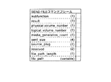
なお、プリンタユニット13がHDDユニット12から参照オブジェクトファイルを取得するための具体的な手順として、IEEE1394で規定されているAV/C Camera Storage Subunit コマンドSendFile(又はCamera Storage Subunit 2.0 コマンドSend File Partial)を発行すればよい。このコマンドでは、参照オブジェクトは、オペランドfile_pathによって指定されることになっているので、上記(1)又は(2)のように、パラメータobject_pathと参照URLとから決定されるパス情報file_pathによって特定される。
【0083】
図5に示すコマンドSEND FILEのコマンドフレームを用いて具体的に説明する。プリンタユニット13はobject_pathで特定可能なデータが必要になると、コマンドSEND FILEのパラメータfile_pathに必要なデータのパスを指定し、同じくパラメータsource_plugにコマンドCAPTURE REFのパラメータsource_plugを指定して、ストレージサブユニット12aにコマンドSEND FILEを発行する。
【0084】
なお、既存のコマンドSEND FILE及びコマンドSEND FILE PARTIALにおいては、ファイル名はMS−DOS(商標)準拠の命名規則である8.3形式 「”ファイル名(八文字)” + ”.” + ”拡張子(3文字)”」を採る必要がある。したがって、印刷ドキュメントデータの作成にあたっては、印刷メインオブジェクト及び参照オブジェクトのファイル名を上記MS−DOS準拠するよう命名する。しかし、既存のHTML等によるWeb−Pageではファイル名を自由な長さで命名することが多い。したがって、印刷メインオブジェクト及び参照オブジェクトのファイル名を自由な長さで命名可能とする場合は、コマンドSEND FILE及びSEND FILE PARTIALにおいて上記命名規則の制限をなくすように拡張する。
【0085】
また、既存のコマンドSEND FILE及びコマンドSEND FILE PARTIALにおいては、パラメータfile_pathには絶対パスを指定する必要がある。パスの解決に前記第1、第2の方法を用いるシステムにおいては、コマンドCAPTURE REFのパラメータobject_pathが相対パスである場合、それを絶対パスに変換したものをコマンドSEND FILE(またはSEND FILE PARTIAL)のパラメータfile_pathに指定し、パラメータobject_pathが絶対パスである場合はそのままの値をパラメータfile_pathに指定しているため、影響はない。
【0086】
しかしパスの解決方法として、上記(1)におけるHDDユニット12においてパスの解決を行う第3の方法を採用する場合、コマンドSEND FILE及びSEND FILE PARTIALのパラメータfile_pathに相対パスを指定することとなる。したがって、コマンドSEND FILE及びSEND FILE PARTIALにおいて、パラメータfile_pathに相対パスを指定できるよう拡張する。
【0087】
また、前述のようにストレージサブユニット12aにカレントディレクトリ情報を設定する方法としてはAV/C Camera Storage Subunitに新規コマンドを追加して設定してもよいし、コントローラ11とHDDユニット12が同一機器である場合は、コントローラ11がAV/C Camera Storage Subunitに内部命令を発効することで設定してもよい。
【0088】
なお前述したが、前記パスを解決する第3の方法において、プリンタユニット13にて印刷ジョブAの実行中は、印刷ジョブAのカレントディレクトリ情報が設定されているべきであり、印刷ジョブA用のデータ送信が完了し以後データ転送が発生しない旨が検知されるまでHDDユニット12におけるカレントディレクトリ情報は変更されるべきではない。しかし、ネットワーク上に複数のコントローラ11が存在し一つのHDDユニット12を共有してプリンタユニット13へそれぞれ印刷指示する場合等では、各々のコントローラ11がHDDユニット12のカレントディレクトリ情報を設定する。したがってこの場合、カレントディレクトリ情報の保持が保証されない。
【0089】
このため、プリンタユニット13がコントローラAから指示された印刷ジョブAを処理中に、コントローラBがHDDユニット12に印刷ジョブBのカレントディレクトリ情報を設定した場合、それを検知できないプリンタユニット13は印刷ジョブAとは無関係のデータを受信する可能性がある。この問題を防ぐため、プリンタユニット13にてHDDユニット12におけるカレントディレクトリ情報の変更を検知する仕組みが必要となる。プリンタユニット13においてAV/C Camera Storage Subunitのカレントディレクトリ情報が変更された旨を検知する仕組みとしては、同じく新規コマンドを追加する方法の他に、SEND FILEコマンド(またはSEND FILE PARTIALコマンド)におけるmedia_generation_countパラメータを応用する方法がある。
【0090】
AV/C Camera Storage Subunitのmedia_generation_countパラメータは本来、AV/C Camera Storage Subunitを備える機器においてSDカード(商標)等のストレージメディアの挿入を検知してその値を変更するものであり、AV/C Camera Storage Subunitのコントローラはコマンドのレスポンスフレームにおけるmedia_generation_countパラメータが変更(media_generation_count + 1)されたか否かを判定することで、ストレージメディアの変更を検知することが出来る。これを応用し、HDDユニット12内のAV/C Camera Storage Subunitが、ストレージメディアの挿入に加えてカレントディレクトリ情報の変更においてもmedia_generation_countパラメータの値を変更することで、プリンタユニット13においてHDDユニット12のカレントディレクトリ情報が変更されたことを検知できる。
【0091】
また、プリンタユニット13がHDDユニット12から参照オブジェクトファイルを取得する方法としては、このようなAV/C Camera Storage SubunitにおけるSEND FILEまたはSEND FILE PARTIALコマンドの他に、ベンダーユニークサブユニット宛てのコマンドを用いたり、HTTP(HyperText Transfer protocol)におけるコマンドGETのようなコマンドを用いてプリンタユニットがHDDユニットから参照オブジェクトファイルを取得してもよい。
【0092】
また、バスリセット時においては、各機器のアドレス情報であるNode_IDや機器間のコネクション情報であるdestination_plugやsource_plugなどのネットワーク接続情報が再設定され、バスリセット前の値から変更される可能性がある。このためバスリセット後に印刷処理を再開したい場合は、まずバスリセット後のネットワーク接続情報に基づいて、コネクションを復旧し次に印刷要求を再送する必要がある。したがってコントローラ11は、HDDユニット12及びプリンタユニット13のバスリセット後のNode_IDを入手し、それに基づいてパラメータRESTORE_PORT subfunctionを指定したAC(Asynchronous Connection) MANAGEコマンドを発行することでコネクションを復旧する。
【0093】
その後に、パラメータRESUME subfunctionを指定したコマンドCAPTURE REFを発行すればよい。この際のコマンドCAPTURE REFのパラメータは、同様にバスリセット後の情報を入手してそれに基づいて設定する。例えば、CAPTURE REFにおけるproducer_node_ID(図4(b)及び(c))などのアドレス情報や、destination_plugやsource_plugなどのネットワーク接続情報においてバスリセット後の値を設定した上でパラメータRESUME subfunctionを指定したコマンドCAPTURE REFを発行する。
【0094】
それによって、プリンタユニット13は、上記コマンドSEND FILE PARTIAL等を用いて印刷オブジェクトを取得し、データ転送動作を再開することができる。
【0095】
以下、図4(b)及び(c)を用いてプル型のプリントを実現する場合の通信シーケンスをそれぞれ<通信シーケンス1><通信シーケンス2>として説明する。
【0096】
<通信シーケンス1>
以下、図4(b)に示すコマンドCAPTURE REFに基づいた通信シーケンスを説明する。
【0097】
図6〜図13は、図2に示された通信シーケンスの詳細なフロー図であり、3つの装置11、12、13間でのコマンドのやりとりを図示している。なお、ここでは、コントローラ11は、STBユニット14が有する1つの機能として実現されている。また、矢印は、コマンドの発行を示し、矢印上又は矢印付近の矩形内には、上の行に、手順番号(丸数字)と処理の内容が示され、下の行に、「:」を挟んで、そのコマンドが属するプロトコル(左側)と内容(右側)が示されている。なお、図中の「PS」は”Printer Subunit”の略であり、「AC」は”Asynchronous Connection”の略であり、「FCP」は、AV/Cコマンド及びその応答に関する規約として採用されているプロトコルである”Function Control protocol, IEC61883 : Digital Interface for Consumer Electric Audio/Video Equipment”の略である。
【0098】
まず、コントローラ11は、図6に示されるように、プリンタサブユニットに対するコントローラ(PS Controller)及びコネクションの確立についてのコントローラ(AC Controller)として、プリンタユニット13に対して機器情報を問い合わせた後に(手順1)、HDDユニット12及びプリンタユニット13に対して、サブユニットの情報を問い合わせる(手順2)。
【0099】
続いて、図7に示されるように、コントローラ11は、HDDユニット12及びプリンタユニット13に対してサブユニットのバージョンを問い合わせることで(手順3)、プリンタユニット13がベンダー拡張されたプリンタサブユニット、つまり、上述のプル型の印刷コマンドCAPTURE REFの実行が可能なサブユニットであることを確認する(手順4)。
【0100】
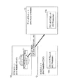
そして、コントローラ11は、図8に示されるように、プリンタユニット13に対してプリントジョブを投入した後に(手順5)、図9に示されるように、HDDユニット12とプリンタユニット13との間にコネクションを確立し(手順6)、続いて、図10に示されるように、印刷コマンドCAPTURE REFを発行することで、プリンタユニット13に対して印刷のトリガを与え(手順7)、印刷を開始させる(手順8)。
【0101】
印刷を開始したプリンタユニット13は、まず、図11に示されるように、HDDユニット12に対してデータ送信を要求することで(手順9)、コントローラ11から指定された印刷オブジェクト(全てのメインオブジェクト及びそこから参照されている全ての参照オブジェクト)をコネクションを介してHDDユニット12から順次取得し、印刷する(手順10)。
【0102】
そして、図12に示されるように、プリンタユニット13での印刷が終了すると(手順11)、コントローラ11は、HDDユニット12とプリンタユニット13との間のコネクションを解放した後に(手順12)、図13に示されるように、プリンタユニット13に対してプリントジョブの終了を通知する(手順13)。このようにして、コントローラ11は、プル型の印刷コマンドCAPTURE REFを用いることで、HDDユニット12に格納された印刷オブジェクトの印刷をプリンタユニット13に実行させることができる。
【0103】
<通信シーケンス2>
次に、図4(c)に示すコマンドCAPTURE REFに基づいた通信シーケンスを説明する。
【0104】
図14〜図21に本シーケンスを図示するが、基本的なシーケンスは前記<通信シーケンス1>と変わらない。また、<通信シーケンス1>における図6〜図13と図示形式は変わらず、応答レスポンスは省略している。また、図14〜図21においては、STBユニット14とHDDユニット12が別の機器として図示しているが、本明細書におけるその他の実施例と同じく、STBユニット14とHDDユニット12が同一の機器であっても構わない。
【0105】
まず、図14に示されるように、コントローラ11はIEEE1394ネットワーク上の機器の情報を収集し、IEEE1394 AV/Cコマンドをサポートする機器の情報及びアドレス(位置)情報であるNode_IDを確認する(手順1)。次にコントローラ11はAV/Cコマンドをサポートする機器に対して、SUBUNIT INFOコマンドを発行することで、各機器がどのサブユニットを所持しているかを確認する(手順2)。
【0106】
ここまでの処理で、コントローラ11は、Node_ID=BBBBであるプリンタユニット13がプリンタサブユニット13aを所持し、Node_ID=CCCC(Producer_Node_ID)であるHDDユニット12がストレージサブユニット12aを所持する(STBユニット14とHDDユニット12が同一機器である場合は自明)ことを把握する。尚、ここでコントローラ11がプリンタサブユニット13aまたはストレージサブユニット12aを所持したユニットを発見できなかった場合は、以後の処理が継続出来ないため、エラーである旨をユーザに返答する。
【0107】
次に図15に示されるように、コントローラ11はHDDユニット12及びプリンタユニット13に対してコマンドVERSIONを発行し、各サブユニットのバージョンを問い合わせる(手順3)。これによりコントローラ11は、プリンタサブユニット13aが図4(c)のコマンドCAPTURE REFを発行可能なプル型のプリントに対応したサブユニットであり、ストレージサブユニット12aが印刷データを送信可能なサブユニットであることを把握する。また、パスの解決に前記第3の方法を採るシステムの場合、ストレージサブユニット12aがカレントディレクトリ情報を設定可能なサブユニットであることを把握する。
【0108】
なお、前記<通信シーケンス1>では、コントローラ11がプリンタサブユニット13aに対して別途コマンドExtended VERSIONを発行しているが、これはプリンタサブユニット13aの規格化内容に依存するものであり、本通信シーケンスでは手順3で発行したコマンドVERSIONへの応答内容で、プリンタサブユニット13aがプル型のプリントに対応する旨を把握可能な例を挙げている。
【0109】
また、上記の方法以外にも、コマンドタイプにSPECIFIC INQUIRYまたはGENERAL INQUIRYを設定したコマンドCAPTUREREFをプリンタサブユニット13aに対して発行し、コマンドCAPTURE REFを実装しているかどうかを問い合わせることで、プリンタサブユニット13aがプル型のプリントに対応しているか否かを把握してもよい。
【0110】
ここで、プリンタサブユニット13aがプル型のプリントに対応していないサブユニットであった場合について述べると、ユーザから印刷指示を受けた印刷ドキュメントが既存のプッシュ型のプリントにて印刷可能であれば、コントローラ11は以後プッシュ型のプリントシーケンスに移行し、プリンタサブユニット13aに対して既存のAV/C Printer subunitの仕様に沿った印刷指示してもよい。一方、ユーザから印刷指示を受けた印刷ドキュメントがプル型のプリントでのみ印刷可能であれば、コントローラ11はユーザに対して何らかのエラーを返してもよい。エラーの内容としては、単に印刷不能である旨を通知してもよいし、該当ドキュメントの印刷に対応したプリンタがIEEE1394ネットワーク上に接続されていない旨を通知してもよい。
【0111】
次に図16に示されるように、コントローラ11はプリンタサブユニット13aに対してJOB QUEUEコマンドadd_jobサブファンクションを発行することで、プリンタユニット13に印刷ジョブを発行する(手順4)。このコマンドによりコントローラ11とプリンタサブユニット13aとの間で、印刷ジョブの受付番号に相当するJob_IDが共有される。このJob_IDは以後、投入した印刷ジョブを指定するために用いられ、図4(b)及び(c)に示されたコマンドCAPTURE REFにおけるパラメータPrint_Job_IDにはこの値を指定する。
【0112】
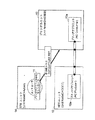
次に図17に示されるように、コントローラ11はHDDユニット12及びプリンタユニット13に対してAC MANAGE関数群を発行することで、印刷データ送信元であるストレージサブユニット12aと印刷データ受信元であるプリンタサブユニット13aとの間にコネクション(AC:Asynchronous Connection)を確立する(手順5)。
【0113】
AC MANAGE関数群に関する詳細は、http://www.1394TA.orgにて入手可能な、「TA Document 1999037 AV/C Command for Management of Enhanced Asynchronous Serial Bus Connections 1.0」に記載されているが、このAC MANAGE関数群の応答レスポンスにより、コントローラ11はストレージサブユニット12a側のコネクションの入力ポート(plug)識別子であるsource_plugとプリンタサブユニット13a側のコネクションの出力ポート(plug)識別子であるdestination_plugとを入手する。
【0114】
このdestination_plugはプリンタサブユニット13aのデータ受信用コネクションを指定するために用いられ、図4(b)及び(c)に示されたコマンドCAPTURE REFにおけるパラメータdestination_plugにはこの値を指定する。同じくsource_plugはストレージサブユニット12aのデータ送信用コネクションを指定するために用いられ、図4(b)及び(c)に示されたコマンドCAPTURE REFにおけるパラメータsource_plugにはこの値を指定する。
【0115】
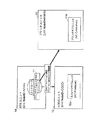
次に図18に示されるように、コントローラ11はプリンタサブユニット13aに対して印刷トリガである図4(c)に示すコマンドCAPTURE REF(パラメータsubufunction = receive)を発行し、プリンタユニットにコマンドCAPTURE REFのパラメータ object_pathで特定可能な印刷ドキュメントの印刷を要求する(手順6)。プリンタサブユニット13aは、コントローラ11に対し暫定的にINTERIMレスポンスを発行しておき、以降の手順7、8を経てストレージサブユニット12a上にある印刷データが必要なくなった時点でコマンドCAPTURE REFに対する最終的な応答レスポンスACCEPTED(途中で復旧不能なエラーが発生した場合はREJECTED)を返す。なお、コントローラ11において応答レスポンスREJECTEDを受け取った場合は、図4(c)に示したコマンドCAPTURE REFのパラメータstatusの値に基づいて、ユーザへのエラー通知または復旧処理を行う。
【0116】
図4(c)に示したコマンドCAPTURE REFのパラメータについては前述したが、プリンタサブユニット13aは、object_pathで指定されたリンクパス情報から特定可能な印刷メインオブジェクトを印刷処理する。なお、前述の通り、パスの解決に前記第2の方法を用いる場合は、パラメータbase_pathを用いてパスの解決を行う。第2の方法以外を用いる場合はパラメータbase_pathは必要なく、空値(NULL)を指定しておいてもよいし、パラメータbase_path自体をCAPTURE REFのコマンドフレームから削除してCAPTURE REFコマンドを規定し直してもよい。
【0117】
尚、パスの解決に前記第3の方法を採る場合は後述する手順7が行われるより前に、コントローラ11がストレージサブユニット12aに対して、ストレージサブユニット12aに新設した新規コマンドまたは内部関数を用いてカレントディレクトリ情報を設定しておく必要がある。また、パラメータdata_sizeは印刷メインオブジェクトのデータサイズであるが、特に必要なければ空値(NULL)を指定しておいてもよいし、パラメータdata_size自体をCAPTURE REFコマンドフレームから削除してCAPTURE REFコマンドを規定し直してもよい。
【0118】
なお、プリンタサブユニット13aに対して同時に発行可能なCAPTUREREFの数は特に限定されるものではなく、任意であるがパスの解決、特にストレージサブユニット12aにてパスの解決を行う前記第3の方法の扱いに注意する必要がある。
【0119】
例えば、プリンタサブユニット13aに対して発行可能なCAPTURE REFは1つであると制限し、プリンタサブユニット13aにおいて1つのCAPTURE REFを処理している間は、パラメータstatusにbusyを設定し、REJECTEDレスポンスを返す実装でもよい。この場合、パスの解決に前記第1、2、3の方法のどれを利用しても問題がない。
【0120】
次に、プリンタサブユニット13aに対して張られたコネクション毎に1つのCAPTURE REFの発行を許すことで、プリンタサブユニット13aに対して複数のCAPTURE REFを同時発行可能とする実装でもよい。この場合、パスの解決に前記第1、2の方法の利用に関しては問題ないが、前記第3の方法を利用する場合は前述のようにストレージサブユニット12aにおいてコネクション毎にカレントディレクトリ情報を設定可能とする必要がある。
【0121】
また、CAPTURE REFの同時発行数に制限を設けず、1つのACを複数のCAPTUREで共用してそれぞれのCAPTURE REFに対応する印刷データを順次受信する実装でも良い。ただしこの場合、HDDユニットにてパスの解決を行う前記第3の方法ではうまくパスを解決出来ないため、第1または第2の方法を利用する必要がある。
【0122】
手順6で印刷要求を受信したプリンタサブユニット13aは、図19に示されるように印刷メインオブジェクトの取得を開始する。具体的にはプリンタサブユニット13aからストレージサブユニット12aに対してデータ送信命令を発行する(手順7)。ここでプリンタサブユニット13aがデータ送信命令を発行するには、印刷データを所持するストレージサブユニット12aのアドレス(位置情報)を知る必要がある。ここで、IEEE1394ではHDDユニットの位置情報は、図4(c)のコマンドCAPTURE REFにおけるパラメータProducer_Node_IDで指定された値で判別可能であり、さらにパラメータsubunit_type及びsubunit_IDによって、HDDユニット12内のサブユニットであるストレージサブユニット12aを判別できる。
【0123】
なお、パラメータsubunit_typeでは、ストレージサブユニット12aのコマンド体系を知ることも出来る。例えばsubunit_typeが、AV/C Camera Storage Subunitを示す値であった場合は、SEND FILEまたはSEND FILE PARTIALコマンドによって印刷データの送信を要求できる旨を把握できる。以後、ストレージサブユニット12aがAV/C Camera Storage Subunitである場合を例にとって説明すると、上記まででアドレス及びコマンド体系が判別したストレージサブユニットに対して、object_pathで指定された印刷メインオブジェクトを図4(c)のコマンドCAPTURE REFのパラメータsource_plugで特定できるコネクションを介して送信するようSEND FILE PARTIAL(またはSEND FILE)コマンドを発行する(手順7)。
【0124】
なお、図4(c)のコマンドCAPTURE REFにおけるパラメータproducer_Node_ID、subunit_type、subunit_ID、source_plugは、手順5にてストレージサブユニット12aとプリンタサブユニット13aとの間に確立されたコネクションの状態を問い合わせることでも入手可能である。この手順5で確立されたコネクションはパラメータdestination_plugで特定可能である。
【0125】
詳しく説明すると、まずパラメータdestination_plugで特定可能なコネクションの状態を内部的に問い合わせることで、プリンタサブユニット13aがコネクションを介して接続されている先のユニットであるHDDユニット12のNode_ID(= Producer_node_ID)とUnit_Plugを入手する。次に入手したUnit_Plugを用いて、Node_IDにて宛先を特定可能なHDDユニット12に対して前記AC MANAGE関数群の一つであるコネクション状態問い合わせコマンド(AC MANAGE STATUSコマンド)を発行することで、subunit_type、subunit_ID及びsubunit_plug(= Source_Plug)を入手する。このように既に確立されているコネクションの状態を問い合わせることでパラメータproducer_Node_ID、subunit_type、subunit_ID、source_plugを入手可能である。
【0126】
なおパラメータproducer_Node_ID、subunit_type、subunit_ID、source_plugを上記方法にて入手する場合は、それぞれのパラメータに空値(NULL)を指定しておいてもよいし、パラメータ自体をCAPTURE REFコマンドフレームから削除してCAPTURE REFコマンドを規定し直してもよい。
【0127】
また、パスの解決に前記第1または第2の方法を用いる場合は、データ送信命令を発効する前にプリンタサブユニット13aにおいてパスの解決を行っておく。
【0128】
データ送信命令を受けたストレージサブユニット12aは、既に確立されているコネクション(AC)を用いてプリンタサブユニット13aに対して印刷データ(ここでは印刷メインオブジェクト)を送信する(手順8)。送信命令がAV/C Camera Storage SubunitにおけるコマンドSEND FILEの場合はデータをそのまま送信し、AV/C Camera Storage SubunitにおけるコマンドSEND FILE PARTIALの場合は分割したデータを送信する。なお、パスの解決に前記第3の方法を用いる場合は、ストレージサブユニット12aにおいてカレントディレクトリ情報を元にデータ送信命令で指定されたパスを解決する。
【0129】
以上、手順7、8によってプリンタサブユニット13aからストレージサブユニット12aに対して印刷メインオブジェクトを要求、受信する処理について説明したが、受信した印刷メインオブジェクト内に、印刷メインオブジェクト以外のデータを示すリンクパス情報が記載されていた場合、該当するデータが印刷処理に必要な参照オブジェクトである場合は随時、手順7、8を繰り返してデータを受信し印刷処理を続行する。
【0130】
また、手順7、8の間に、バスリセットが発生した場合はアドレス情報であるNode_IDが変化するため、前述したようにコネクション(AC)の復旧と印刷トリガであるCAPTURE REFコマンドの再送が必要である。この順序としては、まずコントローラ11がHDDユニット12及びプリンタユニット13のバスリセット後のNode_IDを確認し、次にAC MANAGE関数群を用いてコネクションを復旧する。この際、source_plug及びdestination_plugが変更される可能性もある。次に印刷トリガの再送(再送要求)として、CAPTURE REFコマンドResumeサブファンクションを発行する。
【0131】
このようにパラメータProducer_Node_ID、source_plug、destination_plugの値がバスリセット後に変化する場合は、CAPTURE REFコマンドresumeサブファンクションのパラメータdestination_plugにはバスリセット後の最新の値を設定し、CAPTURE REFにおいてパラメータproducer_Node_ID、subunit_type、subunit_ID、source_plugを指定する必要がある場合は、同じくパラメータproducer_Node_ID、source_plugにはバスリセット後の最新の値を設定する。
【0132】
また、コネクションの状態問い合わせによってパラメータproducer_Node_ID、subunit_type、subunit_ID、source_plugを入手する場合でも同様であり、バスリセットが発生するとコントローラは、まずHDDユニット12及びプリンタユニット13のバスリセット後のNode_IDを確認し、次にAC MANAGE関数群を用いてコネクションを復旧する。次に印刷トリガの再送(再送要求)として、コントローラ11はプリンタサブユニット13aに対しCAPTURE REFコマンドResumeサブファンクションを発行する。このCAPTURE REFコマンドResumeサブファンクションを受信する時点では既にコネクションは復旧済みであるから、プリンタサブユニット13aはこのCAPTURE REFコマンドResumeサブファンクションを受信した後、コネクションの状態を再度問い合わせることで、プリンタサブユニット13aはパラメータproducer_Node_ID、subunit_type、subunit_ID、source_plug等のバスリセット後の最新の値を入手することが出来る。
【0133】
尚、バスリセット後にコネクションの復旧を行うAC MANAGE関数は、前述したようにAC MANAGEコマンドRESTORE_PORTサブファンクションであるが、このコマンドはバスリセット後の接続先Node_ID(プリンタサブユニット13aにとってはProducer_Node_ID)等をパラメータとして含んでいる。したがって、前述のようにバスリセット後のProducer_Node_IDをコネクションの状態を再度問い合わせることで入手する場合は、コネクションの復旧時にAC MANAGEコマンドRESTORE_PORTサブファンクションにて通知され内部保存されたProducer_Node_ID等の値を、プリンタサブユニット13aが内部的に問い合わせて入手する。
【0134】
また、同じくsubunit_typeやsubunit_ID、subunit_plug(= Source_Plug)等をバスリセット後に再度入手する必要がある場合は、上記内部問い合わせで入手したパラメータに基づいて、再度HDDユニット12に対して前記AC MANAGE関数群の一つであるコネクション状態問い合わせコマンド(AC MANAGE STATUSコマンド)を発行することで入手する。
【0135】
次に、コントローラ11はプリンタサブユニット13aから、コマンドCAPTURE REFの応答レスポンスを受けると、図20に示すようにHDDユニット12及びプリンタユニット13に対してAC MANAGE関数群を発行して、ストレージサブユニット12aとプリンタサブユニット13a間のコネクションを解放する(手順9)。
【0136】
最後にコントローラ11はプリンタサブユニット13aに対して、JOB QUEUEコマンドclose_jobサブファンクションを発行する(手順10)。
【0137】
なお、プリンタユニット13は、前述の手順6におけるCAPTURE REFコマンドreceiveサブファンクションを受信した時点で、印刷処理を開始してもよいし、前述の手順7、8をへて印刷ドキュメントを構成する全ての印刷データの受信を完了し手順10が完了した時点で印刷処理を開始してもよい。
【0138】
以上、説明したように本<通信シーケンス2>に基づき、コントローラ11は図4(c)のコマンドCAPTURE REFを用いることで、HDDユニット12に格納された印刷ドキュメントの印刷をプリンタユニット13に実行させることが出来る。
【0139】
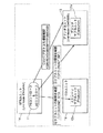
なお、<通信シーケンス1>における手順7または<通信シーケンス2>における手順6において、まずプッシュ型またはプル型の印刷指示を試み、それが拒絶された場合にはもう一方の印刷指示を行う実装でも良い。図22を用いて説明すると、印刷指示の開始に伴い(ステップS201)、コントローラ11はプリンタユニット13に対してまずはプッシュ型のプリントを行うよう指示する(ステップS202)。この指示をプリンタユニット13が拒絶しなかった場合(ステップS203において「yes」)は、印刷指示は完了するが(ステップS208)、それが拒絶された場合(ステップS203において「no」)は、コントローラ11は次にプリンタユニット13に対してプル型のプリントを行うように指示する(ステップS204)。
【0140】
この指示をプリンタユニット13が拒絶しなければ(ステップS205において「yes」)印刷指示は完了する(ステップS208)が、この指示においても拒絶された場合(ステップS205において「no」)はエラーとしてユーザに通知する(ステップS206)。このように取り決めておくことで、プリンタユニットにおいてプル型のプリントであれば良いがプッシュ型のプリントは難しい印刷ドキュメントの印刷要求を受けた場合、それを一端拒絶しておくことで、前記プッシュ型のプリントが難しい印刷ドキュメントをプル型のプリントによって印刷できる。なお、プル型のプリント要求(ステップS202においてプル型の印刷指示)が拒絶された後に、プッシュ型のプリント要求(ステップS204プッシュ型の印刷指示)を行う場合でも同様の効果が奏される。
【0141】
一方、印刷要求の拒絶応答時のステータスに、プッシュ型またはプル型の印刷要求を再度行うよう指示する新たな値を設けることで前記切り替えを行ってもよい。図23を用いて説明すると、印刷指示の開始に伴い(ステップS301)、コントローラ11はプリンタユニット13に対してプッシュ型(またはプル型)のプリント指示を行う(ステップS302)。この指示を受けたプリンタユニット13は、印刷指示が不適であればコントローラ11に印刷指示の拒絶を返す。特に印刷方式の変更によって印刷指示を受領できる場合(例えばプッシュ型ではなくプル型であれば印刷可能である場合)は、印刷指示の拒絶応答におけるresultパラメータに、新たに新設した印刷方式が不適である旨を通知する値をセットする。
【0142】
ステップS302における印刷指示をプリンタユニット13が拒絶しなかった場合(ステップS303において「no」)は、印刷指示は完了する(ステップS308)。しかしステップS302における印刷指示が拒絶された場合(ステップS303 において「yes」)は、コマンドCAPTUREのレスポンスフレーム中のパラメータresult(図4(b)及び(c))の値を確認し、パラメータresultの値が印刷方式が不適である旨を通知する値であればステップS305へ進み、それ以外であればユーザに対してエラーを通知する。パラメータresultの値が印刷方式が不適である旨を通知する値であった場合、コントローラ11はプリンタユニット13に対し、プル型(プッシュ型)のプリント指示を行い(ステップS305)、印刷指示を完了する(ステップS308)。
【0143】
その他にも、コントローラ11が印刷ドキュメントの種類やサイズ、プリンタの能力や状態に応じて判断し、印刷方式(プッシュ型のプリント/プル型のプリント)を切り替える方式をとってもよい。すなわち、コントローラ11が印刷要求コマンド発行前にプリンタユニット13の能力情報や状態情報を問い合わせ、次に、その情報と印刷を要求したい印刷ドキュメントに関する情報を元に、プル型またはプッシュ型のどちらのプリント方式をプリンタユニット13に指示するかを判断し、その判断に基づいてプリンタユニット13に印刷要求を行ってもよい。
【0144】
プリンタの能力情報または状態情報を入手する方法については、本発明は、特に限定されず、既存コマンドを利用してもよいし、既存コマンドでは所望の情報を入手出来ないのであれば、所望の情報を入手するコマンドを新設してもよいし、従来コマンドを拡張してもよい。この方法の一例を図24を用いて説明する。まず前提として、該当ジョブに対してプリンタユニット13が用意できるデータ受信バッファサイズ(A)を問い合わせ可能なコマンドが存在、またはコマンドを新設するものとする。コントローラ11は<通信シーケンス1>における手順7または<通信シーケンス2>における手順6において、印刷指示の開始に伴い(S401)、まずプリンタユニット13に対して前記コマンドを用いてデータ受信バッファサイズ(A)を入手する(ステップS402)。
【0145】
次に、該当ジョブで印刷する印刷ドキュメントを構成するデータの総サイズ(B)を内部的に取得、またはストレージサブユニットに問い合わせることで入手し(ステップS403)、前記データ受信バッファサイズ(A)と前記総サイズ(B)の大きさを比較する(ステップS404)。(A)>(B)である場合、通信トランザクション回数からコントローラ11はプッシュ型の印刷が最適であると判断し、コントローラ11は既存のコマンドCAPTUREを用いてプリンタユニット13にプッシュ型のプリントを行うよう指示する(ステップS405)。(B)>(A)である場合、プッシュ型の印刷を指示してもプリンタユニット13が印刷ドキュメントを全て受信できないと判断し、コントローラ11はコマンドCAPTURE REFを用いてプリンタユニット13にプル型のプリントを行うよう指示する(ステップS406)。このようにして、プリンタの能力や状態に応じて判断し、最適な印刷方式(プッシュ型のプリント・プル型のプリント)を選択して印刷指示を行い、完了する(S407)。
【0146】
なお、上記例では受信バッファサイズと印刷ドキュメントデータの総サイズを判断材料としていたが、本発明は、これに限定されるものではない。例えば、プリンタユニット13が他のジョブを印刷中であれば、データ転送コネクションを確立している時間を短くするために、プッシュ型のプリントを行うよう指示し、他のジョブの印刷中に、あらかじめ他のジョブのデータをプリンタユニット13に対して転送しておいてもよい。その他、プリンタの能力や状態を確認するコマンドとその内容に基づいた判断により、最適な印刷方式を自動的に選択し印刷する印刷システムを構築可能である。
【0147】
ここで、印刷の中止(プリントジョブのキャンセル)について説明する。
プリントジョブのキャンセルはプリンタサブユニット13aに対し、JOB QUEUEコマンドcancel_jobサブファンクションを送信することで行う。
【0148】
前記手順4が行われた時点で、プリントジョブが発行されるが、この時点では印刷データの転送は行われていない状態である。この前記手順4〜手順5の状態でJOB QUEUEコマンドcancel_jobサブファンクションを発行すると、印刷データの転送及び印刷処理が行う前にプリントジョブがキャンセルされる。また、前記手順6においてCAPTURE REFコマンドreceiveサブファンクションが発行された後は、ストレージサブユニット12aとプリンタサブユニット13a間に張られたコネクションを用いてデータが転送されている可能性がある。
【0149】
この手順6〜手順8状態(印刷メインオブジェクトから参照された参照オブジェクトの受信状態も含む)でプリントジョブをキャンセルする場合、同じくそのままJOB QUEUEコマンドcancel_jobサブファンクションを発行し、プリントジョブを終了させる方法がある。しかしコマンドの一対一対応をとるという目的から、プリンタサブユニット13aにおいてCAPTURE REFコマンドreceiveサブファンクション実行中の状態では、JOB QUEUEコマンドcancel_jobサブファンクションを受信してもJOBQUEUEコマンドに対してbusyステータスをつけてREJECT応答を返すこととし、この状態でプリントジョブをキャンセルするには、まずCAPTURE REFコマンドabortサブファンクションを発行してデータ転送を中止させ、続いてJOB QUEUEコマンドcancel_jobサブファンクションを発行してプリントジョブをキャンセルするという実装をとってもよい。
【0150】
次に、<通信シーケンス1>及び<通信シーケンス2>における、プリンタユニット13によるプル型プリントの具体的な動作を一例を挙げて説明する。本例は、印刷メインオブジェクトをバンド毎に処理していき、必要な参照オブジェクトがあれば順次取得しながらラスタライズ等の印刷処理を行う場合の動作例であるが、言うまでもなく、前述したような、印刷ドキュメントを構成するデータを全て受信した後、印刷処理を行う実装でも良い。
【0151】
図25は、プリンタユニット13の機能ブロックを説明するための図である。ここには、IEEE1394バス30で接続された印刷システム(コントローラ11、HDDユニット12、プリンタユニット13)が示されている。
【0152】
プリンタユニット13は、バス30との接続用インターフェイスとなる通信I/F24、プリンタジョブを蓄積するキューの制御部であるキュー制御部23、印刷記述データの解読をしてラスタライザに渡すインタプリタ25と、当該インタプリタより得られた印刷データに基づいてラスタライズするラスタライザ22、ラスタライズされた印刷記述データを記録媒体上に可視記録出力するプリンタエンジン21とから構成されている。
【0153】
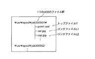
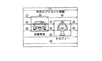
いま、印刷の対象となる印刷オブジェクトは、図26に示される画像を示すデータとする。この画像データは、プリンタで印刷可能な言語(例えば、XHTML形式)で記述され、複数のファイルが含まれている。それら複数のファイルの参照関係は、図27に示されるツリー図の通りである。
【0154】
図27において、トップファイルT「print1.xml」は印刷メインオブジェクトであり、画像データ全体を意味し、画像の配置位置、文字の配置位置や大きさ、あるいは印刷されるべき文字等を表す。リンクファイルL1「car.jpg」はHDDユニット12内のサブディレクトリに格納された自動車の画像、リンクファイルL2「cup.jpg」は同じサブディレクトリに格納されたカップの画像を意味している。トップファイルTには、リンクファイルL1、L2に対するリンクパス情報が記載されており、それぞれトップファイルTの参照オブジェクトである。
【0155】
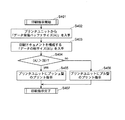
このような印刷オブジェクトについてのプリンタユニット13の印刷動作は、図28に示されるフローチャートの通りである。
まず、コントローラ11から、印刷ジョブの通知として、上記印刷オブジェクトを指定したコマンドCAPTURE REFがプリンタユニット13に発行される(図28のステップS101)。発行された印刷コマンドは、印刷ジョブとして、バス30を介して、プリンタユニット13のキュー制御部23へ渡される。このキュー制御部23は、得られたジョブを格納し、当該ジョブ情報を順番にインタプリタ25に渡す。
【0156】
インタプリタ25は、この印刷ジョブに含まれる、HDDユニット12上の印刷記述データの存在場所(URI;Universal Resource Identifies等)を示すパス情報に基づいて、以下の印刷処理を実行する。
【0157】
つまり、インタプリタ25は、キュー制御部23より渡された信号が印刷ジョブであることとパス情報であることを判定したとき、通信I/F24にチャンネル(コネクション)を設定するように指示をする。これによって設定されたチャネルを介して、前記パス情報をHDDユニット12に渡すとともに、当該印刷ジョブに対応する最上位階層データであるトップファイルTの取得要求をHDDユニット12に発行する(図28のステップS102〜S103)。
【0158】
この要求に従って、HDDユニット12はバス30を介してプリンタユニット13にトップファイルTを送信する(図28のステップS104)。なお、ここでの前記データ転送要求は、任意のファイルを指示して一括で要求、あるいは任意の位置から任意のデータ量を要求(すなわち1ファイルのデータを部分的に要求)する方法であってもよい。
【0159】
ファイルを受信したインタプリタ25は、印刷記述データの種類を判定し、不必要なデータを捨て、印刷されるべきデータをラスタライザ22に渡す。このように印刷されるべきデータを受け取ったラスタライザ22は当該データをラスタライズして、プリンタエンジン21が記録媒体上に印刷する。
【0160】
インタプリタ25は、前記印刷記述データの中から前記トップファイルTにリンクされたリンクファイルLが存在することを検知すると、既に設定したチャンネルとは別のチャンネルを設定するように通信I/F24に指示を出す。新たなチャンネルが設定された時点で、インタプリタ25は、当該オブジェクトの転送要求を出す。これによってオブジェクトデータのリードが開始する(図28のステップS105Yes〜S121〜S122〜S123)。この参照オブジェクトのリードは任意のデータ量ずつなされるが、その値は予め設定しておいてもよいし、あるいは、インタプリタ25がラスタライズに必要な量(例えば数ラスタ分のデータ量)ずつ演算してもよい(図28のステップS111)。
【0161】
ここで図27に示されるように、複数のオブジェクトファイルが存在する場合、インタプリタ25は、対象ファイルごとにその時点でラスタライザ22に前記の量のデータをリードする。
【0162】
前記処理において、先にリードしていたオブジェクトファイルの読み出しデータ量が前記量に達したとき、その時点で一旦転送を中断し、ラスタライズ処理がなされる(図28のステップS112)。前記のラスタライズ処理が終了し、次のデータが必要となった時点で、HDDユニット12が前回停止した位置の次の位置からデータ転送を開始するようになっている(図28のステップS106No〜S107〜S108)。そして1のオブジェクトについてのリードが完了した時点で、前記のように設定されたチャンネルを開放する(図28のステップS109Yes〜S110)。また、すべての印刷ジョブが終了したとき印刷終了通知をコントローラ11に通知する(図28のステップS113〜S114)。
【0163】
図29はこの手順をより具体的に示すものである。以下の手順1、2・・は図29中の▲1▼、▲2▼・・と符合する。なお、この例では複数チャンネルの同時使用可能なバスIEEE1394を使用していることから、以下に記述するように複数のオブジェトのそれぞれに対応するチャネルを設定しているが、同一チャネル(同一回線)で複数のオブジェクトのデータを転送してもよい。
【0164】
手順1.最上位階層のベースデータ1本目をラスタライズする。
手順2.最上位階層のベースデータ2本目をラスタライズする。
手順3.最上位階層のベースデータ2本目をラスタライズ中にリンク情報で示されたオブジェクトファイルを検出する。そこで別途転送チャンネルを設けて該オブジェクトファイルの転送要求をHDDユニット12に出し、これを受けてHDDユニット12は該当するファイルのデータを転送する。ラスタライザはこのデータに基づいてラスタライズ処理をする。
【0165】
手順4.先のオブジェクトファイルが中断した時点で一旦リードを中断し、元の最上位階層のベースデータ2本目をラスタライズする。
手順5.最上位階層のベースデータ3本目をラスタライズする。
【0166】
手順6.最上位階層のベースデータ3本目をラスタライズ中に、リンク情報で示された前記手順3と同じオブジェクトファイルを検出する。当該オブジェクトファイルの前記手順3の手順で展開したデータの続きのデータを要求しファイルをリードしてラスタライズする。
【0167】
手順7.先のオブジェクトファイルが中断した時点で一旦リードを中断し、元の最上位階層のベースデータ3本目をラスタライズする。
手順8.最上位階層のベースデータ3本目をラスタライズ中に、リンク情報で示された前記手順6とは別のオブジェクトファイルを検出する。そこで、前記手順3及び手順6とは別の転送チャンネルを設けて、当該オブジェクトファイルのデータを要求しファイルをリードしてラスタライズする。
【0168】
手順9.2つ目のオブジェクトファイルが中断した時点で一旦リードを中断し、元の最上位階層のベースデータ3本目をラスタライズする。
手順10.最上位階層のベースデータ4本目をラスタライズする。
【0169】
手順11.最上位階層のベースデータ4本目をラスタライズ中に、リンク情報で示された前記手順3及び手順6と同じオブジェクトファイルを検出する。当該オブジェクトファイルの前記手順6で展開したデータの続きのデータを要求しファイルをリードしてラスタライズする。
【0170】
手順12.1つ目のオブジェクトファイルが終了した時点で、リードを終了、転送チャンネルを開放する。元の最上位階層のベースデータ4本目をラスタライズする。
【0171】
手順13.最上位階層のベースデータ4本目をラスタライズ中に、リンク情報で示された前記手順8と同じオブジェクトファイルを検出する。当該オブジェクトファイルの前記手順6の手順で展開したデータの続きのデータを要求しファイルをリードしてラスタライズする。
【0172】
手順14.2つ目のオブジェクトファイルが終了した時点で、リードを終了、転送チャンネルを開放する。元の最上位階層のベースデータ4本目をラスタライズする。
【0173】
手順15.最上位階層のベースデータ5本目をラスタライズする。
手順16.最上位階層のベースデータ6本目をラスタライズする。
このように本印刷システムは、シリアルバス接続により印刷記述データを転送する際に、プリンタユニットが解読することが可能な形式のデータで、当該プリンタユニットがラスラタイズ可能なデータ量ずつ転送データの転送をコントロール(停止・再転送)するようになっている。このようなプル型プリントにより、プリンタ側ではスプール用の大きな印刷記述データバッファが不要となり、更に印刷記述データに対してプリンタ側が必要となったタイミングで別途データを取ってくることが可能となり、ラスタライズ処理を行うときに都合が良い。
【0174】
また、コントローラは、ジョブ(印刷コマンド)の発行だけで済み、印刷オブジェクトを保有することなく、印刷指示を発することができる。
なお、手順1〜手順16の過程でベースデータ(印刷メインオブジェクト)リードまたは該当部分のデータ受信が不可能であると判断した場合、以後の処理が行えないため、その時点で処理を中断する。
【0175】
一方、手順3、手順6、手順8、手順11、手順13においてオブジェクトファイル(参照オブジェクト)のデータ受信が不可能であると判断した場合、その時点で処理を中断してもよいし、空白や×印など該当部分のみデータが受信出来なかった旨ユーザが理解可能な画像を代わりに印刷するようにしてそのまま処理を継続してもよい。
【0176】
以上、本発明に係る印刷システムについて、実施の形態に基づいて説明したが、本発明は、この実施の形態に限定されるものではない。
例えば、コネクションの確立は、コントローラ11だけに限られず、プリンタユニット13によって実行されてもよい。つまり、プリンタユニット13がACControllerとしての機能を有している場合には、プリンタユニット13がHDDユニット12との間のコネクションAsynchronous Connectionを確立してもよい。このときには、図9に示された手順6(コネクションの確立)と図10に示された手順7(印刷トリガ)とが入れ替わる。具体的には、以下の通りである。
【0177】
図30〜図38は、プリンタユニットがAC Controllerとしての機能を有している場合、つまり、プリンタユニットがデータ供給ユニットとの間のコネクションAsynchronous Connectionを確立する場合における3つの装置(ここでは、STBユニット114、プリンタユニット113及びデータ供給ユニット112)間でのコマンドのやりとりを示すフロー図である。なお、これらの図における表記方法は図6〜図13のフロー図と同様である。また、図中の「AC MANAGE API」はコネクションAsynchronous Connectionの管理をするインターフェイス(Application Program Interface)であり、「EUI_64」は”64−bit extended unique identifier”(米国電気電子学会IEEEによる規定)の略である。
【0178】
これら図30〜図38と図6〜図13とを比較して分かるようように、プリンタユニット113がACコントローラとしての機能を有している場合には、その通信シーケンスは、以下の点において、STBユニット114がACコントローラとしての機能を有している場合と異なる。
【0179】
まず、STBユニット114は、プリンタユニット113にプリントジョブを投入する際に(図32の手順5)、Job_ID(print_job_ID)引数の内部EUI_64に、印刷データ供給装置(ここでは、HDDユニット112)のEUI_64をセットしてJobQueueコマンドを発する。ここで、Job_ID引数とは、JobQueueコマンドの引数の1つであり、図39に示されるデータ構造を有し、8バイト長のEUI_64(通常は、JobQueueコマンドを発した送信者のEUI_64(owner_EUI64)がセットされる)と、4バイト長のrecord_ID(JobQueueコマンドに対する返信)とからなる。
【0180】
そして、STBユニット114は、JobQueueコマンドを発した後に、コネクションを確立することなく(コネクションを確立する機能を有していないので)、プリンタユニット113に対して印刷コマンドCAPTURE REFを発行し、印刷トリガを与える(図33の手順6)。このとき、印刷コマンドCAPTURE REF内のパラメータNode_ID(producer_node_ID)、source_plug及びdestination_plugとして空値を指定する。
【0181】
この印刷コマンドCAPTURE REFを受けたプリンタユニット113は、Job_ID引数の中からHDDユニット112のEUI_64を取り出し、そのEUI_64と同じ値を持つNode_IDを検索することで、HDDユニット112のNode_ID(印刷データ供給装置を特定する位置情報)を取得する(図34の手順7)。続いて、プリンタユニット113内部にあるACコントローラ111bは、HDDユニット112とプリンタユニット113とのコネクションを確立することで、上記印刷コマンドCAPTURE REFで空値であったsource_plug及びdestination_plugの値を入手する(図35の手順8)。
【0182】
このようにして、印刷データ供給装置(producer_node_ID)とプラグ(source_plug及びdestination_plug)が判明した後のデータ転送は、図11に示された手順と同様にして行われる(図36の手順10及び手順11)。また、データ転送が終了した後に、プリンタユニット113がSTBユニット114に印刷コマンドCAPTURE REFに対するレスポンスACCEPTEDを返す点も同様である。
【0183】
しかし、コネクションの解放については、プリンタユニット113内部のACコントローラ111bが行う(図37の手順12)。
このような手順によって、プリンタユニットがACコントローラとしての機能を有している場合にも、STBユニットがACコントローラとしての機能を有している場合と同様に、印刷指示を発する装置と印刷オブジェクトを保有する装置とが異なる場合におけるプル型プリントが可能となる。
【0184】
また、プリンタユニットにACコントローラがある場合には、STBユニットは、プリンタユニットに発する印刷コマンドにおいて、印刷データ供給装置の指定に関する全てのパラメータproducer_node_ID、source_plug、subunit_type、subunit_idを空値又は付加しないで、印刷コマンドを送信してもよい。そのときには、プリンタユニットが、AC MANAGE FCPのSTATUSコマンドを、コネクションで接続された印刷データ供給装置(HDDユニット等)に発することで、それらのパラメータproducer_node_ID、source_plug、subunit_type、subunit_idの値を取得し、取得した値に基づいて、データ転送(データの取得)を行えばよい。
【0185】
つまり、プリンタ装置は、コネクションで接続されている印刷データ供給装置に対してコネクション状態の問い合わせを行うことで、ファイル要求の発行先を特定するアドレス情報を取得し、取得したアドレス情報が示す発行先に対してファイル要求を発行する。このような手順であっても、印刷指示を発した装置(STBユニット)とは異なる装置(HDDユニット)に置かれた印刷オブジェクトに対するプル型プリントが可能となる。
【0186】
また、本実施の形態では、印刷システムを構成するコントローラ、データ送信機器(producer)及びデータ受信機器(consumer)の具体例として、それぞれ、STB、HDD装置及びプリンタ装置が挙げられたが、このような装置の他に、コントローラとして、コンピュータ装置、ホームバスコントローラ等が機能してもよいし、データ送信機器として、DSC、DTV、DVD(Digital Versatile Disk)装置、ビデオカメラ装置等のデータ供給装置であってもよいし、データ受信機器として、印刷オブジェクトを蓄積する大容量記憶装置や印刷オブジェクトを遠隔に転送する通信装置等であってもよい。
【0187】
また、本実施の形態では、印刷のトリガとして、コントローラからプリンタユニットに1つの印刷コマンドCAPTURE REFが送信されたが、2以上の印刷コマンドに分割して発行してもよい。例えば、まず、印刷データ供給装置(Producer)に関連しないパラメータ(図4(a)に示されたもの)を含む基本的な印刷コマンドを発行し、続いて、印刷データ供給装置(Producer)に関連するパラメータ(図4(b)に示されたproducer_node_ID, source_plug, subunit_type, subunit_id, object_path)を含む拡張的な印刷コマンドを発行するような手順であってもよい。
【0188】
また、図4(b)及び(c)に示されたコマンドCAPTURE REFパラメータobject_path、及び図4(c)のコマンドCAPTURE REFパラメータBase_pathのデータ長は「variable」であり任意長であるが、現在のAV/Cコマンドでは1コマンド512bytesまでという制限がある。したがって、1つの印刷要求には1つのコマンドCAPTURE REFのみを使用するという制限を設けるのであれば、コマンドCAPTURE REFの他のパラメータとのバランスを考えて、パラメータobject_pathまたはbase_pathの最大長をある程度までに制限する必要がある。
【0189】
一方、1つの印刷要求に複数のコマンドCAPTURE REFを使用可能とした場合、パラメータobject_pathまたはbase_pathのパラメータ長には特に制限は必要ない。1つの印刷要求に複数のコマンドCAPTURE REFを用いる方法の詳細については、特に言及しないが、例えばコマンドCAPTURE REFに当該印刷要求を行うために発行するコマンドCAPTURE REFの総数を指定するパラメータと、その発行順番を指定するパラメータとを新規に追加し、パラメータobject_pathを分割してプリンタサブユニット13aに通知する方法などがある。
【0190】
また、本実施の形態の印刷システムは、IEEE1394バスで接続された機器から構成されたが、機器を接続する伝送路は、このバスだけに限られるものではない。印刷コマンドやファイル取得コマンド等の授受が可能であるならば、本発明に係る印刷手順は、LAN(10BaseT等)やインターネット、Bluetooth(商標)等を下位層とする通信システムにも適用することができる。
【0191】
次に、本実施の形態を適用することによる副次的な効果について述べておく。従来の技術であるIEEE1394 AV/C Printer Subunitにおいてはプッシュ型の印刷形態のみに対応しており、プル型の印刷形態に対応していない。また画像データの印刷が前提となっている。したがって、例えばHTML(Hyper Text Markup Language)で記述された印刷オブジェクトのように、リンクされた複数のファイルからなる印刷オブジェクトをプリントするには、印刷データ供給装置で1枚の画像データをあらかじめ生成してからデータ転送を行うしか方法がなく、印刷データ供給装置に多くの処理能力とメモリ資源が必要とされる。
【0192】
一方、HTMLで記述された印刷オブジェクトのプッシュプリントを可能とした場合、印刷オブジェクトをそのままプリンタ装置に転送(プッシュ)し、印刷画像データをプリンタ装置で生成し印刷することとなるが、この場合でもページ単位で印刷オブジェクトを転送(プッシュ)しておく必要があるために、プリンタ装置側に、1ページ分の印刷オブジェクトを記憶する大容量の記憶バッファが必要とされるという問題がある。また、コントローラは、プリンタ装置における印刷状態を監視したり、印刷の進行状況に応じて印刷オブジェクトを出力する等の出力制御をする必要があり、コントローラにおける処理負荷が大きくなるという問題もある。
【0193】
しかしながら、本実施の形態では、IEEE1394におけるAV/CプリンタコマンドのキャプチャコマンドによるHTMLファイルのプルプリントが可能であり、プリンタ装置に1ページ分の印刷オブジェクトを記憶する大容量の記憶バッファが必要とされるという問題や、コントローラにおける処理負荷が大きくなるという問題、印刷データ供給装置に多くのメモリと処理能力が必要とされるという問題が解消される。
【0194】
また、本実施の形態におけるコントローラ11はそれ自体が単体の機器であってもよいし、印刷データ供給装置またはプリンタ装置と同一の機器であってもよい。プリンタ装置が受信する印刷指示には、印刷オブジェクトが格納されている場所(印刷データ供給装置)の指定が含まれ、印刷指示を受け取ったプリンタ装置は、指定された格納場所に置かれた印刷オブジェクトを取得してプリント(プル型のプリント)を実行するので、印刷指示を発行する装置と印刷オブジェクトを保有している装置とが同一の場合だけに限られず、それらの装置が異なる場合においても印刷が可能となる。つまり、印刷指示を発行する印刷制御装置とは異なる場所(印刷データ供給装置)に印刷オブジェクトが置かれている場合であっても、そのような印刷オブジェクトの印刷が可能となり、プル型のプリンタ装置が持っている機能を有効に発揮させることが可能な印刷システムが実現される。
【0195】
このように、本実施の形態を適用したプリントシステムは、コントローラとは異なる場所(独立した印刷データ供給装置)に格納された印刷オブジェクトを印刷させる等の多様なシステム構成に応じた柔軟な印刷が可能である。
【0196】
また、プル型のプリントでは印刷データを受信(プル)するためにプリンタ装置が印刷データ供給装置に対してデータ送信命令を発行する必要がある。データ送信命令を発行するためにはプリンタ装置が印刷データ供給装置の装置位置(アドレス)やコマンド体系、データ送信命令時のパラメータといった情報を予め把握しなければならない。
【0197】
しかし、本実施の形態では、これらの情報を印刷要求コマンドであるAV/CPrinter SubunitのコマンドCAPTURE REFに含ませるか、または、プリンタ装置が印刷データ供給装置との間に張られたコネクションの状態を問い合わせることで容易に入手可能である。
【0198】
これによって、印刷データ供給装置の種類(タイプ)ごとに情報の授受に関するコマンド体系や順序等が異なる場合に、プリンタ装置は、その差を認識したうえで、印刷データ供給装置の特性に合ったプロトコルに従って印刷オブジェクトを取得することができるので、印刷オブジェクトの転送や印刷処理の効率が向上され得る。
【0199】
また、IEEE1394規格においては、印刷データ供給装置のアドレスに関して、IEEE1394規格固有のバスリセットの影響を考慮する必要がある。このバスリセットは、IEEE1394ネットワーク上の機器の電源on/off、ケーブルの挿抜毎に発生するものであり、バスリセットが発生するとネットワーク上の機器のアドレスが再設定される。したがって、プリンタ装置においてバスリセットを検知した場合、印刷データ供給装置の新しいアドレスを再度把握する必要がある。
【0200】
本実施の形態では、IEEE1394伝送路におけるアドレスが再設定された場合に、前記印刷データ供給装置と前記プリンタ装置の間のコネクションを復旧し、次に、前記プリンタ装置に対する印刷要求を再送し、前記再送要求に対し、前記プリンタ装置は、要求された印刷に必要なデータ受信を再開する。その上で、装置位置(アドレス)等をコマンドCAPTURE REFに含ませる方式では装置位置を設定するパラメータにバスリセット後の印刷データ供給装置のアドレス情報に基づく値を設定し、コネクションの状態を問い合わせる場合は再送要求を受けた後に状態を問い合わせている。これにより、バスリセット後でもあっても正しい値を容易に取得可能である。
【0201】
また、HTML等で記述されたドキュメントでは、内部で他の印刷オブジェクトへのリンク(リンクパス情報)が記述されている。このリンクパス情報が、ある基準点からの相対位置によってファイルの位置を指定する相対パスである場合、相対パスを絶対位置でファイルを指定する絶対パスに変換する手法が必要となる。本実施の形態では、パスの解決するための第1〜第3の方法を用いることで絶対パスを容易に取得可能である。
【0202】
【発明の効果】
以上の説明から明らかなように、本発明に係る印刷データ転送方法は、伝送路で接続された印刷データ供給装置とプリンタ装置間に印刷データを転送するための方法であって、前記印刷データ供給装置が保持する印刷データを印刷させるための、前記印刷データ供給装置の属性情報を伴って前記プリンタ装置に対して印刷要求する段階と、前記印刷要求に応じ、前記プリンタ装置が前記属性情報に基づいて前記印刷データ供給装置に印刷データを要求する段階と、前記印刷データの要求に応じ、前記印刷データ供給装置が印刷データを前記プリンタ装置に送信する段階とを有する。
【0203】
これにより、本発明を適用した印刷データ転送方法等では、プリンタ装置からのデータ取得要求に基づいて印刷を実行するプル型の印刷形態(Pull Print)が実現可能であり、本発明の実用的価値は極めて高い。さらに、本発明の印刷ファイル取得システム等によれば、リンクパス情報が相対パスである場合にも、ファイルを取得することができる。さらに、本発明のデータ転送方法等によれば、バスリセット時においても、正しいデータを取得することができる。
【図面の簡単な説明】
【図1】本発明の実施の形態における印刷システムのシステムモデルを示す図である。
【図2】図1に示されたシステムモデルにおける通信シーケンスを示す図である。
【図3】図2に示されたフェーズobject pushの詳細な通信シーケンスを示す図である。
【図4】(a)は、プッシュ型プリントを前提とする従来の印刷コマンドCAPTURE、(b)は、プッシュ型及びプル型プリントが可能であり、(c)はプル型プリントのみが可能な本発明に係るコマンドCAPTURE REFのAV/Cコマンドフレームを示す。
【図5】AV/C Camera Storage SubunitにおけるコマンドSEND FILEのコマンドフレームである。
【図6】図2に示された通信シーケンス(<通信シーケンス1>)の詳細なフロー図の一つ(機器確認フェーズ)である。
【図7】図2に示された通信シーケンス(<通信シーケンス1>)の詳細なフロー図の一つ(バージョン確認フェーズ)である。
【図8】図2に示された通信シーケンス(<通信シーケンス1>)の詳細なフロー図の一つ(ジョブ投入フェーズ)である。
【図9】図2に示された通信シーケンス(<通信シーケンス1>)の詳細なフロー図の一つ(コネクション確立フェーズ)である。
【図10】図2に示された通信シーケンス(<通信シーケンス1>)の詳細なフロー図の一つ(印刷トリガフェーズ)である。
【図11】図2に示された通信シーケンス(<通信シーケンス1>)の詳細なフロー図の一つ(ファイル転送フェーズ)である。
【図12】図2に示された通信シーケンス(<通信シーケンス1>)の詳細なフロー図の一つ(コネクション解放フェーズ)である。
【図13】図2に示された通信シーケンス(<通信シーケンス1>)の詳細なフロー図の一つ(ジョブ終了フェーズ)である。
【図14】図2に示された通信シーケンス(<通信シーケンス2>)の詳細なフロー図の一つ(機器確認フェーズ)である。
【図15】図2に示された通信シーケンス(<通信シーケンス2>)の詳細なフロー図の一つ(バージョン確認フェーズ)である。
【図16】図2に示された通信シーケンス(<通信シーケンス2>)の詳細なフロー図の一つ(ジョブ投入フェーズ)である。
【図17】図2に示された通信シーケンス(<通信シーケンス2>)の詳細なフロー図の一つ(コネクション確立フェーズ)である。
【図18】図2に示された通信シーケンス(<通信シーケンス2>)の詳細なフロー図の一つ(印刷トリガフェーズ)である。
【図19】図2に示された通信シーケンス(<通信シーケンス2>)の詳細なフロー図の一つ(ファイル転送フェーズ)である。
【図20】図2に示された通信シーケンス(<通信シーケンス2>)の詳細なフロー図の一つ(コネクション解放フェーズ)である。
【図21】図2に示された通信シーケンス(<通信シーケンス2>)の詳細なフロー図の一つ(ジョブクローズフェーズ)である。
【図22】プリンタユニットの印刷動作の一例を示すフローチャートである。
【図23】プリンタユニットの印刷動作の他の例を示すフローチャートである。
【図24】プリンタユニットの印刷動作のさらに他の例を示すフローチャートである。
【図25】プリンタユニットの機能ブロックを説明するための図である。
【図26】印刷の対象となる印刷オブジェクトの一例(画像)を示す図である。
【図27】図26に示された印刷オブジェクトの構成要素の関係を示すツリー図である。
【図28】プリンタユニットの印刷動作を示すフローチャートである。
【図29】プリンタユニットの印刷動作の具体例を示す図である。
【図30】プリンタユニットがACコントローラとしての機能を有している場合における通信シーケンスの詳細なフロー図の一つ(機器確認フェーズ)である。
【図31】同通信シーケンスの詳細なフロー図の一つ(バージョン確認フェーズ)である。
【図32】同通信シーケンスの詳細なフロー図の一つ(ジョブ投入フェーズ)である。
【図33】同通信シーケンスの詳細なフロー図の一つ(印刷トリガフェーズ)である。
【図34】同通信シーケンスの詳細なフロー図の一つ(Node_IDの検索フェーズ)である。
【図35】同通信シーケンスの詳細なフロー図の一つ(コネクション確立フェーズ)である。
【図36】同通信シーケンスの詳細なフロー図の一つ(ファイル転送フェーズ)である。
【図37】同通信シーケンスの詳細なフロー図の一つ(コネクション解放フェーズ)である。
【図38】同通信シーケンスの詳細なフロー図の一つ(ジョブ終了フェーズ)である。
【図39】Job_ID引数のデータ構造を示す図である。
【図40】従来の印刷手順を示す通信シーケンス図である。
【符号の説明】
11、900 コントローラ
12、112 HDDユニット
12a、112a ストレージサブユニット
13、113、910 プリンタユニット
13a、113a プリンタサブユニット
14、114 STBユニット
111a PSコントローラ
111b ACコントローラ
21 プリンタエンジン
22 ラスタライザ
23 キュー制御部
24 通信I/F
25 インタプリタ
30 バス[0001]
TECHNICAL FIELD OF THE INVENTION
The present invention relates to a method for transferring print data to a printer device, and more particularly to a pull-type printing method in which the printer device requests a print data supply source to supply print data.
[0002]
[Prior art]
Attempts have been made to connect a printer device to an AV (Audio Visual) device such as a digital camera or a digital broadcast receiver (STB; Set Top Box), and to directly print images captured and received by the AV device to the printer device. I have. However, unlike personal computers, AV devices such as STBs generally do not include a large-capacity auxiliary storage device such as a hard disk device or a CD-ROM drive device, and few devices have a function of updating their own firmware. Therefore, it is preferable to avoid a situation in which different driver software is installed for each type of printer device to be connected. Therefore, a flexible connection method that enables printing by connecting freely selected AV equipment and a printer without installing software specific to the equipment as long as the equipment conforms to a certain standard. desired.
[0003]
One of the measures to meet such a demand is an AV / C protocol defined by the IEEE 1394 standard (for example, see Non-Patent Document 1). The AV / C protocol provides a framework that determines the minimum necessary standard protocol for connection of AV equipment, maintains compatibility, and enables each manufacturer to individually enhance the performance of the equipment. In the AV / C protocol, an AV / C Printer Subunit is one that negotiates an AV / C command particularly for a printer.
[0004]
FIG. 40 is a sequence diagram illustrating an example of a communication procedure when an AV device such as a digital camera prints out an image to a printer device according to an existing AV / C Printer Subunit. Here, a communication sequence when a controller 900 connected via an IEEE 1394 bus outputs a print object such as an image held therein to a printer unit (printer device) 910, and a command and a response at that time are shown.
[0005]
First, the controller 900 acquires version information from the printer unit 910, generates a print job by specifying the job identifier job_ID to the printer unit 910, and then establishes a logical transfer channel (connection for asynchronous data transfer; Asynchronous Connection). Establish.
[0006]
Then, by sending the AV / C command CAPTURE to the printer unit 910, the controller 900 designates a print object to be output, and instructs to receive the print object. The object is output (pushed) to the printer unit 910.
[0007]
When printing is completed and the printer unit 910 returns an end status ACCEPTED response to the controller 900, the controller 900 disconnects the transfer channel Asynchronous Connection, closes the print job, and then polls the status of the job in the printer unit 910. I do.
[0008]
In this way, the AV device outputs the print object to the printer device according to the AV / C Printer Subunit, so that the print output can be performed without installing the driver software specific to the printer device.
[0009]
[Non-patent document 1]
IEEE Std 1394-1995, Standard for a High Performance Serial Bus
[0010]
[Problems to be solved by the invention]
However, the print command CAPTURE in the AV / C Printer Subunit has a push-type print form (Push Print) in which, after the issuance of the command, the controller that has issued the command outputs a print object owned by the controller to the printer device. It is assumed that the printer device does not support a pull-type printing mode (Pull Print) in which a printer device itself retrieves a necessary print object from a necessary location (performs printing based on a data acquisition request from the printer device). There is one problem.
[0011]
In a document described in HTML or the like, a link (link path information) to another print object is described internally. This link path information may be represented not only by an absolute path (uniquely indicating the position of the file) but also by a relative path (indicating the position of the file by a relative position from a certain reference point). Therefore, when the link path information is a relative path, there is a second problem that a file to be printed cannot be obtained using the same method as the absolute path.
[0012]
Further, in the IEEE 1394 standard, the address of the print data supply device is affected by the bus reset inherent in the IEEE 1394 standard. That is, since the bus reset occurs every time the power supply of the device on the IEEE 1394 network is turned on / off and the cable is inserted / removed, correct data may not be obtained when the address is reset (changed). There are issues.
[0013]
Therefore, the present invention has been made in view of such a situation, and a first object of the present invention is to provide a print data transfer method and the like that can effectively exhibit the functions of a pull-type printer device. The purpose of.
[0014]
It is a second object of the present invention to provide a print file acquisition system capable of acquiring a file even when the link path information is a relative path.
Further, a third object is to provide a data transfer system or the like that can acquire correct data even at the time of bus reset.
[0015]
[Means for Solving the Problems]
In order to achieve the first object, a method for transferring print data between a print data supply device and a printer device connected by a transmission path, the method comprising: printing print data held by the print data supply device. Making a print request to the printer device with attribute information of the print data supply device, and in response to the request, the printer device makes a data request to the print data supply device based on the attribute information. And printing the print data to the printer device in response to the data request.
[0016]
Here, the printer device receives link path information to the print target data as the attribute information, and converts the print data specified by the link path information described in the print target data body and the print data into the print data. A request may be made to the supply device, or, for example, a link file in which link path information to the print target data is described in XHTML-Print format or the like is received, and the print data supply device is The print data specified by the link path information described in the received link file may be requested.
[0017]
More specifically, in conformity with IEEE 1394, a printer device that receives a capture command of an AV / C printer command acquires print target data and data such as JPEG, PNG, and text linked from the print target data. To do so, it issues an AV / C command and receives data via the already established connection.
[0018]
When the link path information specified by the attribute information or the link path information described in the print target data is a relative path indicating a position from a certain reference point, the attribute information further includes the link path information. May be specified. Further, the reference position of the link path information described in the print target data may be extracted from the link path information of the print target data specified by the attribute information in the print request. Further, the printer device may hold these reference positions until transmitting a completion notification for the print request.
[0019]
Further, the data request and the transmission may be repeated. Further, the connection may be established by a printer device, or may be established by a print control device other than the print data supply device and the printer device.
[0020]
Further, the attribute information may be address information for specifying the print data supply device. Specifically, the address information may be Node_ID or EUI_64 in the
[0021]
Further, the attribute information may be connection information for specifying an input port on the print data supply device side in the connection. Specifically, the connection information may be a subunit_plug_id in the
[0022]
Further, the attribute information may be type information for specifying a type of the print data supply device. Specifically, the type information may be Subunit_Type in the
[0023]
Further, the printer device may receive the print request from a print control device other than the print data supply device, or may send a completion notification to the print request after completing reception of data required for the requested printing. You may send it.
[0024]
Further, the print request may include a first parameter group not related to the print data supply device and a second parameter group related to the print data supply device. At this time, the print request may be one command including the first parameter group and the second parameter group, or the print request may include a first command including the first parameter group, It may be separated into a second instruction including a second parameter group.
[0025]
Further, when the address in the transmission path is reset, the connection between the print data supply device and the printer device is restored, and then a print request to the printer device is retransmitted. The printer device may resume receiving data required for the requested printing. Here, the retransmission request may be based on the address information of the print data supply device after the bus reset.
[0026]
Further, a reference position of the link path information may be set in the print data supply device. The reference position for the print data supply device may be set for each connection.
[0027]
Further, when the print object acquired from the print data supply device includes link information indicating a reference to another print object, the timing of printing the reference print object is reached. Further, by requesting the print data supply device to transmit the print object of the reference destination indicated by the link information, the print object of the reference destination may be acquired, and the acquired print object may be printed.
[0028]
Further, the print data supply device may notify that the reference position has been changed by a response to the request for the print data, or the print data supply device may include a removable recording medium, The fact that the reference position has been changed may be notified using a parameter indicating that the medium has been loaded. It is preferable that a reference position of the link path information is set for the print data supply device before a print request to the printer device, and the setting of the reference position is not changed until a completion notification for the print request is received. preferable.
[0029]
The attribute information includes first link path information for specifying, by an absolute path, a storage location of the first print data to be printed, among the print data stored by the print data supply device, and the first print data. And the reference position of the second print data referred to by the reference.
[0030]
In addition, the print data transfer method further includes, prior to the print request, confirming whether a print data supply device that holds print data and a printer device that prints print data are connected on the transmission path, If at least one of the print data supply device and the printer device is not connected, it is preferable to include a step of notifying a user of an error.
[0031]
The print request to the printer device includes an inquiry as to whether the printer device has a function of requesting print data from the print data supply device, and the print data transfer method further includes: The method may include a step of responding to the inquiry. Here, if the printer device has responded to the inquiry that it does not have the function, the print data supply device does not receive a request for print data from the printer device, Print data may be transmitted to the printer device. Further, the print data transfer method may further include the printer device responding to the inquiry that the function is not provided with the function, and the print data to be printed has the function described above. When printing can be performed only by the user, a step of notifying the user of an error may be included.
[0032]
The present invention can be realized not only as such a print data transfer method, but also as a print system including a print control device, a print data supply device, and a printer device that execute these print data transfer methods. It can also be realized as a single unit of these devices, or as a program that causes a general-purpose computer such as a personal computer to execute its characteristic operation and function. Then, it goes without saying that the program can be distributed via a computer-readable recording medium such as a CD-ROM or a transmission medium such as the Internet.
[0033]
In order to achieve the second object, a print file acquisition system according to the present invention includes: a storage unit for storing link path information designating a storage location of a print file; and a link path information acquired from the storage unit. If a part or all of the path is a relative path indicating a relative position from a predetermined reference point, based on the reference position data indicating the predetermined reference point, the relative path, the absolute path of the print file The image processing apparatus includes a conversion unit that converts the absolute path indicating the position, and an obtaining unit that obtains a print file that can be specified from the absolute path converted by the conversion unit.
[0034]
Further, in order to achieve the third object, a print data transfer system according to the present invention includes a print data supply device and a printer device connected by a transmission path, and transmits the print data supply device to the printer device. A print data transfer system for transferring print data to the print data supply device and the printer device after a bus reset, and when the print data transfer is resumed, the print data after the bus reset. Network information acquiring means for acquiring network connection information of the supply device and the printer device; and restoring a data transfer connection between the print data supply device and the printer device based on the network connection information obtained from the network information acquisition device. Connection recovery means and the network information acquisition means. It has a print request retransmission means for retransmitting the print request based on the network connection information, and an acquisition unit based on the retransmitted print request acquires print object by the printing requesting retransmission means.
[0035]
BEST MODE FOR CARRYING OUT THE INVENTION
Hereinafter, embodiments of the present invention will be described in detail with reference to the drawings.
FIG. 1 is a diagram illustrating a system model of a printing system according to the present embodiment. This system model is composed of a
[0036]
The
[0037]
Note that the unit corresponds to an AV device, and the subunit manages the function of the AV device (virtual functional unit). The combination of the subunits becomes a unit, and what functional unit the unit is divided into is determined as appropriate. Further, the subunit is a virtual functional unit and does not always match the hardware configuration.
[0038]
The feature in this figure is that, as shown in the exchange (command and response) between the
[0039]
The print object is transmitted via an already established connection for asynchronous data transfer (Asynchronous Connection). If described as a controller-subunit model in the IEEE1394 AV / C standard, the
[0040]
FIG. 2 is a diagram showing a communication sequence in the system model shown in FIG. 1 and corresponds to FIG. 40 in the related art. The difference from FIG. 40 is the exchange in the phase object push. In the sequence of this drawing, a command CAPTURE REF is issued from the
[0041]
Note that the command CAPTURE REF corresponds to an extended command of the command CAPTURE in which a function for enabling pull-type printing is added while following the function of the conventional command CAPTURE. The command CAPTURE REF includes a reference (a parameter indicating the location of the print object; link path information) to a print object placed in a device (unit, subunit) different from the device that issued the command. Therefore, the printing operation of the printing object by the
[0042]
Specifically, the communication sequence shown in FIG. 3 is performed in the phase object push of FIG. First, when the
[0043]
The
[0044]
When the acquisition of all the print objects is completed by repeating the transfer sequence of the main object and the reference object as many times as necessary, the
[0045]
Note that the response ACCEPTED in response to the command CAPTURE REF is returned at a stage where it is not necessary to receive data (print main object and reference object) constituting the print job when proceeding with the printing process, so that the response to the CAPTURE REF is once performed. Is received, the trouble of re-establishing a connection disconnected for reprocessing due to a paper jam during printing can be avoided. More specifically, if the implementation of the
[0046]
FIG. 4 is a diagram for explaining a detailed instruction format of the command CAPTURE REF while comparing it with a conventional command CAPTURE. FIG. 4A shows a conventional command CAPTURE on the premise of push-type printing. FIG. 4B shows an AV / C command frame of the command CAPTURE REF according to the present invention, in which push-type printing and pull-type printing are possible, and FIG. 4C shows only pull-type printing. Here, the operands (parameters added to the instruction) and the length (the number of bytes) in the AV / C command frame of both commands are shown. The command frames in FIGS. 4B and 4C are only examples, and the command frame shown in FIG. 4B and the command frame shown in FIG. 4C may be merged. Needless to say, the parameters may be arranged in any order.
[0047]
As shown in FIG. 4A, a conventional command CAPTURE on the premise of push-type printing includes, as operands, a parameter subfunction for specifying a specific operation, return status parameters and result, and a printer unit (connection). A parameter destination_plug that specifies an input port on the data receiving device (consumer) side, a parameter print_job_ID that specifies a print job to be commanded, a parameter image_format_specifier that specifies the format of a print object such as JPEG or GIF, and data of a print object to be transferred A parameter data_size for specifying the size and a parameter for specifying the number of pixels as image data. Meter image_size_x and image_size_y, in the command response at Nin1 print designation, designation of parameters next_pic and next_page information about print object to be next transferred is set has a structure as possible.
[0048]
On the other hand, as shown in FIG. 4B, the command CAPTURE REF capable of push-type and pull-type printing in the present embodiment has, as operands, the parameters subfunction, status, and parameter used in the conventional command CAPTURE. In addition to the result, destination_plug, print_job_ID, image_format_specifier, data_size, next_page, and five new parameters: producer_node_ID, source_plug_unit, subscription_subunit, and subscription_subunit.
[0049]
The parameter producer_node_ID is an operand that specifies a location where the print object to be pulled is located, that is, a data transmission device (producer) such as an HDD unit. Here, if the controller that issues the print command also serves as a data transmitting device (producer) (has a print object), the value of the parameter producer_node_ID is set to the value of the own device. This may allow the printing of the print object owned by the user.
[0050]
The parameter source_plug is an operand that specifies an input port on the data transmission device (producer) side in the connection. This parameter source_plug is one of the parameters obtained when the
[0051]
The parameters subunit_type and subunit_id are operands for specifying the type of data transmission device (producer) (for example, distinction of DSC (Digital Still Camera) / STB / DTV (Digital TV) / HDD) and its device number. The type of the data transmitter is used to identify the type of the command when the system and order of the commands related to the transmission and reception of information are changed based on the difference between the device characteristics and the difference between the versions.
[0052]
The parameter object_path is an operand indicating a storage location of a print object (main object) in a hierarchical file system in a data transmission device (producer) such as an HDD. Specifically, link path information of the print main object is stored.
[0053]
Also, in the command CAPTURE REF in which only pull-type printing according to the present embodiment shown in FIG. 4C is possible, the parameters subfunction, status, result, destination_plug, print_job_ID, and the parameters used in the conventional command CAPTURE are used as operands. In addition to image_format_specifier and data_size, six new parameters producer_node_ID, source_plug, subunit_type, subunit_id, object_path, and base_path have been added.
[0054]
Note that data_size, producer_node_ID, source_plug, subunit_type, subunit_ID, and base_path, each of which has a “question mark” in the drawing, are not indispensable in performing a print request, but are present in the
[0055]
The parameter producer_node_ID is an operand that specifies the location where the print object to be pulled is located, that is, the address of a data transmission device (producer) such as an HDD unit. Here, when the controller that issues the print command also serves as a data transmitting device (producer) (has a print object), the value of the own device can be set as the value of the parameter producer_node_ID. It is possible to print a print object owned by the user.
[0056]
The parameter source_plug is an operand that specifies an input port on the data transmission device (producer) side in the connection. This parameter source_plug is one of the parameters obtained when the
[0057]
The parameters subunit_type and subunit_id are operands for specifying the type of data transmission device (producer) (for example, distinction of DSC (Digital Still Camera) / STB / DTV (Digital TV) / HDD) and its device number. The type of the data transmitter is used to identify the type of the command when the system and order of the commands related to the transmission and reception of information are changed based on the difference between the device characteristics and the difference between the versions.
[0058]
The parameter object_path is an operand indicating a storage location of a print object (main object) in a hierarchical file system in a data transmission device (producer) such as an HDD. Specifically, link path information of the print main object is stored.
[0059]
The parameter base_path, which will be described in detail later, is used as a reference position of the relative path when resolving the relative path, and when the link path information of the reference object extracted from the print main object in the printer unit is a relative path. This parameter is used to convert link path information into an absolute path using this parameter. As will be described later, even when the object_path is a relative path, the object_path is converted into an absolute path using this parameter as a reference position of the relative path.
[0060]
By referring to such added parameters, the printer unit that has received the command CAPTURE REF acts as a controller for a data transmitting device (producer) while specifying a sub unit and a data path while specifying a sub object and a data path. By requesting and acquiring a print object such as an object, pull-type printing can be performed. At this time, information is exchanged with the data transmitting device in accordance with the command system and order specified by the parameter subunit_type.
[0061]
Note that in the command CAPTURE REF shown in FIG. 4B, some of the parameters used in the conventional command CAPTURE, image_size_x, image_size_y, and next_pic, are not used. This is because the command format shown in FIG. 4B targets a file including link information such as an HTML file.
[0062]
When raster image data is used instead of such a file, all the parameters used in conventional commands may be included. Further, in the command CAPTURE REF shown in FIG. 4C, next_page is not additionally used. This may be included in the command frame, but is omitted since it is not essential.
[0063]
The command CAPTURE REF is based on the premise that the reference object (the print object referred to by the main object) exists in the same unit and subunit as the main object and can be transmitted through the same connection path.
[0064]
Here, the link path information will be described.
The link path information is information for uniquely specifying a file position as described above. For example, a file path (for example, c: \ windows \ regedit.exe) that specifies a file position on a local area, or the Internet URL (Uniform Resource Locator, for example, http://www.panasonic.co.jp/products/tv/index.html) that specifies a file location on the network. In an HTML file or the like, link path information is described as either an absolute path or a relative path.
[0065]
An absolute path uniquely specifies the position of data using only that information, while a relative path describes the path from a certain reference position to the target data. Can be specified. When performing pull-type printing, there is no particular problem as long as the link path information is all absolute paths, but a part or all of the link path information may be a relative path. In this case, it is necessary for the
[0066]
The solution of the URL (Uniform Resource Locator) when the printer unit that receives the command CAPTURE REF pulls the HTML file placed on the data transmission device (producer) is as follows.
(1) When URL is specified by relative path
If the URL is specified by a relative path, the final URL (absolute path) is resolved by any of the three methods described below.
[0067]
First, a first method for performing path resolution in the
This method is optimal when a CAPTURE REF command in which the base_path parameter is omitted is employed to simplify the command frame as shown in FIG. Although the load on the
[0068]
As described above, the point in the first method for solving the path is that the
[0069]
Next, a second method for performing path resolution in the
This method is limited to a case where a CAPTURE REF command in which a base_path parameter which is a reference position of a relative path is added to a command frame as shown in FIG. This method has the advantage that the path can be resolved reliably for each print instruction and the path can be surely resolved as compared with the third method. Specifically, when the parameter object_path (A) in FIG. 4C is a relative path, the relative path is converted into an absolute path using the reference position of the relative path specified by the parameter base_path. For example, when the parameter object_path is a relative path “./1394ta.html” and the parameter base_path is “c: / windows /”, the final file path is “c: / windows / 1394” from “base_path + object_path”. .Html ".
[0070]
Using the absolute path derived in this manner, a request for transmission of the print main object is made to the
[0071]
As described above, the command CAPTURE REF parameter base_path is used for resolving the path each time the link path information described in the print main object is a relative path. Therefore, the
[0072]
As described above, the point of the second method of solving the path is that the
[0073]
Finally, a third method of solving a path in the
This method is a method in which the
[0074]
As described above, the point of the third method of solving the path is that the
[0075]
The method of setting the current directory information is arbitrary. For example, when the
[0076]
In the third method for resolving the relative path using the current directory information, the current directory information of the print job A should be set while the print job A is being executed by the
[0077]
(2) When the URL is specified by an absolute path
The specification (B) of the reference object is an absolute file path File_path, for example, <image src = "http://www.1394ta.com/1394ta_subnav-taHome.gif" usemap = "# mainNavMap" b When width = “430” height = “16”>, the absolute path is used without change. That is, the final file path File_path is “http://www.1394ta.com/1394ta_subnav-taHome.gif”. At this time, the print object indicated by the URL of the absolute path is obtained directly from the local storage (cache) or the Internet.
[0078]
Needless to say, the print object on the removable medium is obtained by setting the designation (B) of the reference object to the removable medium.
[0079]
The correspondence when the storage position of the print main object is different from the storage position of the reference object differs for each of the first to third methods for solving the path described above. As an example, a case in which a still image (storage position “D: /a.jpg”) stored in a CD-ROM, a DVD-ROM, or the like is printed in a pull-type print mode will be described. In this case, the
[0080]
When the first and third methods are used for solving the path, since the storage positions of the HTML data and the still image data are different, the link path information described in the HTML data created by the
[0081]
On the other hand, when the second method is used for solving the path, the link path information described in the HTML data created by the
[0082]
As a specific procedure for the
[0083]
This will be specifically described using the command frame of the command SEND FILE shown in FIG. When the
[0084]
In the existing command SEND FILE and command SEND FILE PARTIAL, the file name is 8.3 format ““ file name (eight characters) ”+”. ”Which is a naming rule based on MS-DOS (trademark). It is necessary to use "+" extension (3 characters) "". Therefore, when creating the print document data, the file names of the print main object and the reference object are named so as to conform to the MS-DOS. However, in the existing Web-Page based on HTML or the like, the file name is often given an arbitrary length. Therefore, if the file names of the print main object and the reference object can be named freely, the commands SEND FILE and SEND FILE PARTIAL are extended so as to eliminate the restrictions on the naming rules.
[0085]
In the existing commands SEND FILE and SEND FILE PARTIAL, it is necessary to specify an absolute path in the parameter file_path. In a system that uses the first and second methods for path resolution, if the parameter object_path of the command CAPTURE REF is a relative path, a result obtained by converting the relative path to an absolute path is converted to a command SEND FILE (or SEND FILE PARTIAL). If the parameter "file_path" is specified and the parameter "object_path" is an absolute path, the value is directly used as the parameter "file_path", so there is no influence.
[0086]
However, when the third method of solving a path in the
[0087]
As described above, as a method of setting the current directory information in the
[0088]
As described above, in the third method for resolving the path, while the print unit A is executing the print job A, the current directory information of the print job A should be set. The current directory information in the
[0089]
Therefore, when the controller B sets the current directory information of the print job B in the
[0090]
The media_generation_count parameter of the AV / C Camera Storage Subunit originally detects the insertion of a storage medium such as an SD card (trademark) in a device having the AV / C Camera Storage Subunit and changes the value. The Storage Subunit controller can detect the change of the storage medium by determining whether or not the media_generation_count parameter in the response frame of the command has been changed (media_generation_count + 1). Applying this, the AV / C Camera Storage Subunit in the
[0091]
As a method for the
[0092]
Further, at the time of bus reset, network connection information such as Node_ID which is address information of each device and destination_plug and source_plug which are connection information between devices are reset and may be changed from the values before the bus reset. . Therefore, when the printing process is to be resumed after the bus reset, it is necessary to first restore the connection based on the network connection information after the bus reset, and then retransmit the print request. Therefore, the
[0093]
Thereafter, a command CAPTURE REF specifying the parameter RESUME subfunction may be issued. At this time, the parameters of the command CAPTURE REF are similarly set based on the information obtained after the bus reset. For example, a command CAPTURE that specifies a parameter RESUME subfunction after setting a value after bus reset in address information such as producer_node_ID (FIGS. 4B and 4C) in CAPTURE REF and network connection information such as destination_plug and source_plug. Issue REF.
[0094]
Thereby, the
[0095]
Hereinafter, the communication sequence for realizing the pull-type printing using FIGS. 4B and 4C will be described as <
[0096]
<
Hereinafter, a communication sequence based on the command CAPTURE REF shown in FIG. 4B will be described.
[0097]
FIGS. 6 to 13 are detailed flowcharts of the communication sequence shown in FIG. 2 and illustrate the exchange of commands among the three
[0098]
First, as shown in FIG. 6, the
[0099]
Subsequently, as shown in FIG. 7, the
[0100]
Then, after submitting a print job to the
[0101]
The
[0102]
Then, as shown in FIG. 12, when the printing in the
[0103]
<
Next, a communication sequence based on the command CAPTURE REF shown in FIG. 4C will be described.
[0104]
This sequence is shown in FIGS. 14 to 21. The basic sequence is the same as the <
[0105]
First, as shown in FIG. 14, the
[0106]
In the processing so far, the
[0107]
Next, as shown in FIG. 15, the
[0108]
In the above <
[0109]
In addition to the above method, a command CAPTUREREF in which the command type is set to SPECIFIC INQUIRY or GENERAL INQUIRY is issued to the
[0110]
Here, the case where the
[0111]
Next, as shown in FIG. 16, the
[0112]
Next, as shown in FIG. 17, the
[0113]
For details on the AC MANAGE function group, see http: // www. 1394TA. The "TA Document 1999037 AV / C Command for Management of Enhanced Asynchronous Serial Bus Connections 1.0" available at org, is described in the AC MANAGE function group. The source_plug which is the input port (plug) identifier of the connection on the 12a side and the destination_plug which is the output port (plug) identifier of the connection on the
[0114]
This destination_plug is used to specify the data reception connection of the
[0115]
Next, as shown in FIG. 18, the
[0116]
Although the parameters of the command CAPTURE REF shown in FIG. 4C have been described above, the
[0117]
When the third method is used to resolve the path, the
[0118]
The number of CAPTUREREFs that can be issued to the
[0119]
For example, the number of CAPTURE REFs that can be issued to the
[0120]
Next, an implementation may be adopted in which a plurality of CAPTURE REFs can be simultaneously issued to the
[0121]
Further, without limiting the number of simultaneous CAPTURE REFs to be issued, one AC may be shared by a plurality of CAPTUREs and the print data corresponding to each CAPTURE REF may be sequentially received. However, in this case, it is necessary to use the first or the second method because the path cannot be resolved successfully by the third method in which the HDD unit resolves the path.
[0122]
Upon receiving the print request in step 6, the
[0123]
Note that the parameter subunit_type can also know the command system of the
[0124]
Note that the parameters producer_Node_ID, subunit_type, subunit_ID, and source_plug in the command CAPTURE REF in FIG. 4C can also be obtained by inquiring about the state of the connection established between the
[0125]
More specifically, first, by internally querying the connection state that can be specified by the parameter destination_plug, the Node_ID (= Producer_node_ID) and the Node_ID of the
[0126]
When the parameters producer_Node_ID, subunit_type, subunit_ID, and source_plug are obtained by the above-described method, a null value (NULL) may be specified for each parameter, or the parameter itself may be deleted from the CAPTURE REF command frame. The REF command may be redefined.
[0127]
When the first or second method is used to resolve a path, the path is resolved in the
[0128]
The
[0129]
The processing of requesting and receiving a print main object from the
[0130]
If a bus reset occurs between
[0131]
When the values of the parameters Producer_Node_ID, source_plug, and destination_plug change after the bus reset, the latest values after the bus reset are set in the parameter destination_plug of the CAPTURE REF command resume subfunction, and the parameters prutadu_e, When it is necessary to specify the subunit_ID and source_plug, the latest values after the bus reset are set in the parameters producer_Node_ID and source_plug.
[0132]
The same applies to the case where the parameters producer_Node_ID, subunit_type, subunit_ID, and source_plug are obtained by a connection status inquiry.If a bus reset occurs, the controller first checks the Node_ID of the
[0133]
The AC MANAGE function for restoring the connection after the bus reset is the AC MANAGE command RESTORE_PORT subfunction as described above. This command includes the connection destination Node_ID after the bus reset (Producer_Node_ID for the
[0134]
If it is necessary to obtain subunit_type, subunit_ID, subunit_plug (= Source_Plug), etc. again after the bus reset, the AC MANAGE function group is again transmitted to the
[0135]
Next, upon receiving a response to the command CAPTURE REF from the
[0136]
Finally, the
[0137]
It should be noted that the
[0138]
As described above, based on this <
[0139]
In the
[0140]
If this instruction is not rejected by the printer unit 13 ("yes" in step S205), the print instruction is completed (step S208), but if the instruction is also rejected ("no" in step S205), the user is notified as an error. (Step S206). By arranging in this way, if a printer unit receives a print request for a print document, it may be a pull type print, but a push type print is difficult. Print documents that are difficult to print using pull-type printing. The same effect can be obtained when a push-type print request (push-type print instruction in step S204) is made after the pull-type print request (pull-type print instruction in step S202) is rejected.
[0141]
On the other hand, the switching may be performed by providing a new value instructing to perform the push-type or pull-type print request again in the status at the time of the rejection response of the print request. With reference to FIG. 23, at the start of a print instruction (step S301), the
[0142]
If the print instruction in step S302 has not been rejected by the printer unit 13 ("no" in step S303), the print instruction is completed (step S308). However, if the print instruction in step S302 is rejected (“yes” in step S303), the value of the parameter “result” (FIGS. 4B and 4C) in the response frame of the command CAPTURE is checked, and the value of the parameter “result” is checked. If the value is a value notifying that the printing method is inappropriate, the process proceeds to step S305; otherwise, an error is notified to the user. If the value of the parameter result is a value notifying that the printing method is inappropriate, the
[0143]
In addition, a method may be adopted in which the
[0144]
The present invention is not particularly limited with respect to a method of obtaining the capability information or the status information of the printer. The present invention may use an existing command. If the desired information cannot be obtained by the existing command, the desired information may be obtained. May be newly provided, or a conventional command may be extended. An example of this method will be described with reference to FIG. First, it is assumed that there is a command that can inquire the data reception buffer size (A) that can be prepared by the
[0145]
Next, the total size (B) of the data constituting the print document to be printed in the job is acquired internally or obtained by inquiring of the storage subunit (step S403), and the data reception buffer size (A) is obtained. The size of the total size (B) is compared (step S404). If (A)> (B), the
[0146]
In the above example, the receiving buffer size and the total size of the print document data are used as the determination material, but the present invention is not limited to this. For example, if the
[0147]
Here, cancellation of printing (cancellation of a print job) will be described.
The print job is canceled by transmitting a job QUEUE command cancel_job subfunction to the
[0148]
At the time when the
[0149]
When canceling the print job in the state of steps 6 to 8 (including the reception state of the reference object referred to from the print main object), a method of issuing the job QUEUE command cancel_job subfunction as it is and terminating the print job is also available. is there. However, in the state where the CAPTURE REF command receive sub-function is being executed in the
[0150]
Next, a specific operation of the pull-type printing by the
[0151]
FIG. 25 is a diagram for explaining functional blocks of the
[0152]
The
[0153]
It is assumed that the print object to be printed is data indicating an image shown in FIG. The image data is described in a language (for example, XHTML format) that can be printed by the printer, and includes a plurality of files. The reference relationship between the plurality of files is as shown in the tree diagram of FIG.
[0154]
In FIG. 27, a top file T “print1.xml” is a print main object, which means the entire image data, and represents an image layout position, a character layout position and size, a character to be printed, and the like. The link file L1 “car.jpg” means an image of a car stored in a subdirectory in the
[0155]
The printing operation of the
First, the
[0156]
The
[0157]
That is, when determining that the signal passed from the
[0158]
In response to this request, the
[0159]
The
[0160]
When the
[0161]
Here, as shown in FIG. 27, when there are a plurality of object files, the
[0162]
In the above processing, when the read data amount of the previously read object file reaches the above amount, the transfer is temporarily interrupted at that time, and the rasterizing process is performed (step S112 in FIG. 28). When the rasterizing process is completed and the next data is needed, the
[0163]
FIG. 29 shows this procedure more specifically. The following
[0164]
[0165]
[0166]
Step 6. While rasterizing the third base data of the highest hierarchy, the same object file as in the
[0167]
Step 8. While rasterizing the third base data in the highest hierarchy, an object file different from the procedure 6 indicated by the link information is detected. Therefore, a transfer channel different from the
[0168]
Step 9. When the second object file is interrupted, the read is interrupted once, and the third base data of the original highest hierarchy is rasterized.
Procedure 10. The fourth base data of the highest hierarchy is rasterized.
[0169]
[0170]
[0171]
[0172]
[0173]
As described above, the present printing system transfers the transfer data in a format that can be decoded by the printer unit when transferring the print description data through the serial bus connection, in an amount of data that can be rasterized by the printer unit. Control (stop / retransmit). Such pull-type printing eliminates the need for a large print description data buffer for spooling on the printer side, and further enables separate data to be fetched from the print description data when the printer side needs it. It is convenient when performing processing.
[0174]
Further, the controller only needs to issue a job (print command), and can issue a print instruction without holding a print object.
If it is determined that the base data (print main object) cannot be read or the data of the corresponding part cannot be received in the course of the
[0175]
On the other hand, if it is determined in
[0176]
As described above, the printing system according to the present invention has been described based on the embodiment, but the present invention is not limited to this embodiment.
For example, the connection establishment is not limited to the
[0177]
FIGS. 30 to 38 show three devices (here, STBs) when the printer unit has a function as an AC Controller, that is, when the printer unit establishes a connection Asynchronous Connection with the data supply unit. FIG. 4 is a flowchart showing exchange of commands among a
[0178]
As can be seen by comparing FIGS. 30 to 38 with FIGS. 6 to 13, when the
[0179]
First, when submitting a print job to the printer unit 113 (
[0180]
After issuing the JobQueue command, the
[0181]
Upon receiving the print command CAPTURE REF, the
[0182]
In this way, data transfer after the print data supply device (producer_node_ID) and plug (source_plug and destination_plug) are identified is performed in the same manner as the procedure shown in FIG. 11 (
[0183]
However, the connection is released by the
According to such a procedure, when the printer unit has the function as an AC controller, similarly to the case where the STB unit has the function as an AC controller, the device that issues the print instruction and the print object are Pull-type printing can be performed when the device is different from the one held.
[0184]
When the printer unit has an AC controller, the STB unit sets all parameters producer_node_ID, source_plug, subunit_type, and subunit_id in the print command issued to the printer unit to null values or without adding any of them. A print command may be transmitted. At that time, the printer unit issues an AC MANAGE FCP STATUS command to the print data supply device (HDD unit or the like) connected by the connection, thereby acquiring the values of the parameters producer_node_ID, source_plug, subunit_type, and subunit_id, Data transfer (data acquisition) may be performed based on the acquired values.
[0185]
In other words, the printer device obtains the address information that specifies the destination of the file request by making an inquiry about the connection state to the print data supply device that is connected by the connection, and obtains the destination information indicated by the obtained address information. Issues a file request to Even with such a procedure, pull-type printing can be performed on a print object placed on a device (HDD unit) different from the device (STB unit) that issued the print instruction.
[0186]
Further, in the present embodiment, the STB, the HDD device, and the printer device are described as specific examples of the controller, the data transmission device (producer), and the data reception device (consumer) which constitute the printing system, respectively. In addition to a simple device, a computer device, a home bus controller, or the like may function as a controller, or a data supply device such as a DSC, a DTV, a DVD (Digital Versatile Disk) device, or a video camera device may serve as a data transmission device. The data receiving device may be a large-capacity storage device that stores print objects, a communication device that remotely transfers print objects, or the like.
[0187]
In the present embodiment, one print command CAPTURE REF is transmitted from the controller to the printer unit as a print trigger, but it may be divided into two or more print commands and issued. For example, first, a basic print command including parameters (shown in FIG. 4A) not related to the print data supply device (Producer) is issued, and then, a basic print command related to the print data supply device (Producer) is issued. An extended print command including parameters (producer_node_ID, source_plug, subunit_type, subunit_id, object_path) shown in FIG. 4B may be used.
[0188]
The data length of the command CAPTURE REF parameter object_path shown in FIG. 4B and FIG. 4C and the data length of the command CAPTURE REF parameter Base_path shown in FIG. 4C are “variable” and are arbitrary. The AV / C command has a limit of 512 bytes per command. Therefore, if there is a restriction that only one command CAPTURE REF is used for one print request, the maximum length of the parameter object_path or base_path may be increased to some extent in consideration of the balance with other parameters of the command CAPTURE REF. It needs to be restricted.
[0189]
On the other hand, when a plurality of commands CAPTURE REF can be used for one print request, there is no particular limitation on the parameter length of the parameter object_path or base_path. Although details of a method of using a plurality of commands CAPTURE REF for one print request are not particularly described, for example, a parameter for specifying the total number of commands CAPTURE REF to be issued for performing the print request in the command CAPTURE REF, and the issue thereof There is a method of newly adding a parameter for designating the order, dividing the parameter object_path, and notifying the
[0190]
Further, the printing system according to the present embodiment is configured by devices connected by the IEEE1394 bus, but the transmission path connecting the devices is not limited to this bus. If it is possible to transmit and receive a print command, a file acquisition command, and the like, the printing procedure according to the present invention can be applied to a communication system in which a LAN (10BaseT or the like), the Internet, Bluetooth (trademark), or the like is a lower layer. it can.
[0191]
Next, a secondary effect of applying the present embodiment will be described. The
[0192]
On the other hand, if push printing of a print object described in HTML is enabled, the print object is transferred (pushed) to the printer device as it is, and print image data is generated and printed by the printer device. Since it is necessary to transfer (push) the print objects in page units, there is a problem that a large-capacity storage buffer for storing the print objects for one page is required on the printer device side. In addition, the controller needs to monitor the printing state of the printer device and perform output control such as outputting a print object in accordance with the progress of printing, which causes a problem that the processing load on the controller increases.
[0193]
However, in the present embodiment, pull-printing of an HTML file can be performed by a capture command of an AV / C printer command in IEEE1394, and a large-capacity storage buffer for storing one page of print objects is required in the printer device. And the problem that the processing load on the controller increases and the print data supply device requires a large amount of memory and processing capability.
[0194]
Further, the
[0195]
As described above, the print system to which the present embodiment is applied can perform flexible printing according to various system configurations such as printing a print object stored in a location (an independent print data supply device) different from the controller. It is possible.
[0196]
Also, in pull-type printing, the printer device needs to issue a data transmission command to the print data supply device in order to receive (pull) print data. In order to issue a data transmission command, the printer must know in advance information such as the device position (address) of the print data supply device, a command system, and parameters at the time of the data transmission command.
[0197]
However, in the present embodiment, such information is included in the command CAPTURE REF of the AV / CPPrinter Subunit, which is a print request command, or the state of a connection established between the printer device and the print data supply device. It is easily available by inquiry.
[0198]
With this, when the command system and the order of information transmission / reception differ depending on the type (type) of the print data supply device, the printer recognizes the difference, and then recognizes the difference and sets a protocol suitable for the characteristics of the print data supply device. Therefore, the efficiency of transfer of print objects and print processing can be improved.
[0199]
In the
[0200]
In this embodiment, when the address on the
[0201]
In a document described in HTML or the like, a link (link path information) to another print object is described therein. If this link path information is a relative path that specifies the position of a file by a relative position from a certain reference point, a method of converting the relative path into an absolute path that specifies a file by an absolute position is required. In the present embodiment, an absolute path can be easily obtained by using the first to third methods for solving a path.
[0202]
【The invention's effect】
As is apparent from the above description, the print data transfer method according to the present invention is a method for transferring print data between a print data supply device and a printer device connected by a transmission path, Requesting the printer device to perform a print request with attribute information of the print data supply device for printing the print data held by the device; and, in response to the print request, the printer device based on the attribute information. Requesting the print data from the print data supply device, and transmitting the print data to the printer device in response to the request for the print data.
[0203]
As a result, in the print data transfer method and the like to which the present invention is applied, a pull-type print mode (Pull Print) for executing printing based on a data acquisition request from a printer device can be realized, and the practical value of the present invention Is extremely high. Further, according to the print file acquisition system or the like of the present invention, a file can be acquired even when the link path information is a relative path. Further, according to the data transfer method and the like of the present invention, correct data can be obtained even at the time of bus reset.
[Brief description of the drawings]
FIG. 1 is a diagram illustrating a system model of a printing system according to an embodiment of the present invention.
FIG. 2 is a diagram showing a communication sequence in the system model shown in FIG.
FIG. 3 is a diagram showing a detailed communication sequence of a phase object push shown in FIG. 2;
4A is a conventional print command CAPTURE premised on push-type printing, FIG. 4B is a book capable of performing push-type and pull-type printing, and FIG. 4C is a book capable of performing only pull-type printing. 4 shows an AV / C command frame of a command CAPTURE REF according to the invention.
FIG. 5 is a command frame of a command SEND FILE in the AV / C Camera Storage Subunit.
FIG. 6 is a detailed flowchart (device confirmation phase) of the communication sequence (<
FIG. 7 is one detailed flow diagram (version confirmation phase) of the communication sequence (<
FIG. 8 is one detailed flowchart (job input phase) of the communication sequence (<
9 is one detailed flow chart (connection establishment phase) of the communication sequence (<
FIG. 10 is one detailed flow chart (print trigger phase) of the communication sequence (<
FIG. 11 is one detailed flow chart (file transfer phase) of the communication sequence (<
FIG. 12 is one detailed flow chart (connection release phase) of the communication sequence (<
FIG. 13 is one detailed flow chart (job end phase) of the communication sequence (<
14 is one detailed flow chart (device confirmation phase) of the communication sequence (<
FIG. 15 is one detailed flowchart (version confirmation phase) of the communication sequence (<
FIG. 16 is a detailed flowchart (job input phase) of the communication sequence (<
FIG. 17 is one detailed flow chart (connection establishment phase) of the communication sequence (<
FIG. 18 is a detailed flowchart (print trigger phase) of the communication sequence (<
FIG. 19 is one detailed flow chart (file transfer phase) of the communication sequence (<
FIG. 20 is one detailed flow chart (connection release phase) of the communication sequence (<
FIG. 21 is a detailed flowchart (job close phase) of the communication sequence (<
FIG. 22 is a flowchart illustrating an example of a printing operation of the printer unit.
FIG. 23 is a flowchart illustrating another example of the printing operation of the printer unit.
FIG. 24 is a flowchart illustrating still another example of the printing operation of the printer unit.
FIG. 25 is a diagram illustrating functional blocks of a printer unit.
FIG. 26 is a diagram illustrating an example (image) of a print object to be printed.
FIG. 27 is a tree diagram illustrating a relationship between components of the print object illustrated in FIG. 26;
FIG. 28 is a flowchart illustrating a printing operation of the printer unit.
FIG. 29 is a diagram illustrating a specific example of a printing operation of the printer unit.
FIG. 30 is one of detailed flow charts (device confirmation phase) of a communication sequence when the printer unit has a function as an AC controller.
FIG. 31 is one of detailed flow diagrams (version confirmation phase) of the communication sequence.
FIG. 32 is one detailed flowchart (job input phase) of the communication sequence.
FIG. 33 is one detailed flow chart (print trigger phase) of the communication sequence.
FIG. 34 is one of detailed flowcharts of the communication sequence (a search phase of Node_ID).
FIG. 35 is one of detailed flow charts (connection establishment phase) of the communication sequence.
FIG. 36 is one of detailed flow charts (file transfer phase) of the communication sequence.
FIG. 37 is one of detailed flowcharts of the same communication sequence (connection release phase).
FIG. 38 is a detailed flowchart (job end phase) of the communication sequence.
FIG. 39 is a diagram showing a data structure of a Job_ID argument.
FIG. 40 is a communication sequence diagram showing a conventional printing procedure.
[Explanation of symbols]
11,900 controller
12, 112 HDD unit
12a, 112a storage subunit
13, 113, 910 Printer unit
13a, 113a Printer subunit
14, 114 STB unit
111a PS controller
111b AC controller
21 Printer Engine
22 Rasterizer
23 Queue control unit
24 Communication I / F
25 Interpreter
30 bus
Claims (59)
前記印刷データ供給装置が保持する印刷データを印刷させるため、前記印刷データ供給装置の属性情報を伴って前記プリンタ装置に対して印刷要求する段階と、
前記要求に応じ、前記プリンタ装置が前記属性情報に基づいて前記印刷データ供給装置にデータ要求する段階と、
前記データ要求に応じ、前記印刷データ供給装置が印刷データを前記プリンタ装置に送信する段階
とを有することを特徴とする印刷データ転送方法。A method for transferring print data between a print data supply device and a printer device connected by a transmission path,
Requesting a print request to the printer device with attribute information of the print data supply device to print the print data held by the print data supply device;
In response to the request, the printer device requests data from the print data supply device based on the attribute information;
Transmitting said print data to said printer device in response to said data request.
ことを特徴とする請求項5記載の印刷データ転送方法。6. The print data supply device according to claim 5, further comprising a removable recording medium, and notifying that the reference position has been changed using a parameter indicating that the recording medium has been mounted. Print data transfer method described.
前記属性情報に、さらに前記リンクパス情報の基準位置を指定することを特徴とする請求項1記載の印刷データ転送方法。When the link path information specified in the attribute information or the link path information described in the print data is a relative path indicating a position from a certain reference point,
2. The print data transfer method according to claim 1, wherein a reference position of the link path information is further specified in the attribute information.
前記印刷要求の段階において前記属性情報として受け取った前記リンクパス情報の基準位置を前記印刷要求に対する完了通知を送信するまで保持する
ことを特徴とする請求項8記載の印刷データ転送方法。The printer device includes:
9. The print data transfer method according to claim 8, wherein a reference position of the link path information received as the attribute information at the stage of the print request is held until a completion notification for the print request is transmitted.
前記印刷要求における属性情報で指定されたリンクパス情報から抽出した前記リンクパス情報の基準位置を
前記印刷要求に対する完了通知を送信するまで保持する
ことを特徴とする請求項10記載の印刷データ転送方法。The printer device includes:
11. The print data transfer method according to claim 10, wherein a reference position of the link path information extracted from the link path information specified by the attribute information in the print request is held until a completion notification for the print request is transmitted. .
印刷対象データへのリンクパス情報が記載されたリンクファイルを受信し、前記印刷データ供給装置に対し、前記受信したリンクファイルに記載されたリンクパス情報で特定される印刷データを要求することを特徴とする請求項1記載の印刷データ転送方法。The printer device includes:
Receiving a link file in which link path information to print target data is described, and requesting the print data supply device for print data specified by the link path information described in the received link file. The print data transfer method according to claim 1, wherein
前記印刷データ供給装置と前記プリンタ装置の間のコネクションを復旧し、
次に、前記プリンタ装置に対する印刷要求を再送し、
前記再送要求に対し、前記プリンタ装置は、要求された印刷に必要なデータ受信を再開する
ことを特徴とする請求項1記載の印刷データ転送方法。When the address in the transmission path is reset,
Restoring the connection between the print data supply device and the printer device,
Next, resend the print request to the printer device,
2. The print data transfer method according to claim 1, wherein the printer restarts receiving data required for the requested printing in response to the retransmission request.
ことを特徴とする請求項1記載の印刷データ転送方法。The attribute information includes, among print data stored by the print data supply device, first link path information that specifies, by an absolute path, a storage position of first print data to be printed, and reference by the first print data. The print data transfer method according to claim 1, further comprising a relative path reference position indicating a storage position of the second print data to be stored.
ことを特徴とする請求項1記載の印刷データ転送方法。The print data transfer method further includes, prior to the print request, confirming whether a print data supply device that holds print data and a printer device that prints print data are connected on the transmission path, and 2. The print data transfer method according to claim 1, further comprising a step of notifying a user of an error when at least one of the data supply device and the printer device is not connected.
前記印刷データ転送方法は、さらに、前記プリンタ装置が前記問い合わせに対して返答する段階を含む
ことを特徴とする請求項1記載の印刷データ転送方法。The print request to the printer device includes an inquiry as to whether the printer device has a function of requesting print data from the print data supply device,
2. The print data transfer method according to claim 1, wherein the print data transfer method further includes a step of the printer device responding to the inquiry.
ことを特徴とする請求項36記載の印刷データ転送方法。If the printer device responds to the inquiry that it does not have the function, the print data supply device receives the print data from the printer device without receiving the request for print data. 37. The print data transfer method according to claim 36, wherein the print data is transmitted to the printer device.
ことを特徴とする請求項36記載の印刷データ転送方法。The print data transfer method may further include a step in which the printer device replies to the inquiry that the function is not provided, and the print data to be printed is provided only by the printer device having the function. 37. The print data transfer method according to claim 36, further comprising a step of notifying a user of an error when printing is possible.
ことを特徴とする請求項1記載の印刷データ転送方法。The print data transfer method further includes, prior to the print request, inquiring at least one of the print data supply device and the printer device for a status, and responding to the inquiry by the printer device in response to the inquiry. A pull-type print that prints print data while requesting print data from the device, or a push-type print that prints print data transmitted from the print data supply device without the printer device requesting print data. The method according to claim 1, further comprising the step of determining whether to perform printing.
前記プリンタ装置が備えるデータ受信バッファのサイズと印刷の対象となる印刷データのサイズとを比較し、
前記データ受信バッファのサイズが前記印刷データのサイズより大きい場合に、前記プッシュ型の印刷を行うと決定し、前記データ受信バッファのサイズが前記印刷データのサイズ以下である場合に、前記プル型の印刷を行うと決定する
ことを特徴とする請求項39記載の印刷データ転送方法。In the step of determining whether to perform the pull-type or push-type printing,
Compare the size of the data reception buffer provided in the printer device and the size of the print data to be printed,
When the size of the data reception buffer is larger than the size of the print data, it is determined that the push-type printing is to be performed. The print data transfer method according to claim 39, wherein it is determined that printing is performed.
前記印刷データ供給装置は印刷データを保持し、
前記プリンタ装置は、
前記印刷データ供給装置に保持された印刷データを印刷させるため、前記印刷データ供給装置の属性情報を伴って発行された印刷要求を受信する手段と、
前記要求に応じ、前記属性情報に基づいて前記印刷データ供給装置にデータ要求する手段と、
前記データ要求に応じ、前記印刷データ供給装置から送信された印刷データを受信する手段と、
前記印刷データを印刷する手段
とを備えることを特徴とする印刷システム。A print system comprising a print data supply device and a printer device connected by a transmission path,
The print data supply device holds print data,
The printer device includes:
Means for receiving a print request issued with attribute information of the print data supply device, in order to print the print data held in the print data supply device,
Means for making a data request to the print data supply device based on the attribute information in response to the request;
Means for receiving print data transmitted from the print data supply device in response to the data request,
Means for printing the print data.
前記印刷データ要求手段は、前記印刷データ供給装置に対し、前記受信したリンクファイルに記載されたリンクパス情報で特定される印刷データを要求する
ことを特徴とする請求項41記載の印刷システム。The printer device includes means for receiving a link file in which link path information to data to be printed is described,
The printing system according to claim 41, wherein the print data requesting unit requests the print data supply device for print data specified by link path information described in the received link file.
前記印刷データ供給装置と前記プリンタ装置の間のコネクションを復旧し、
次に、前記プリンタ装置に対する印刷要求を再送し、
前記再送要求に対し、前記プリンタ装置は、要求された印刷に必要なデータ受信を再開する
ことを特徴とする請求項41記載の印刷システム。When the address in the transmission path is reset,
Restoring the connection between the print data supply device and the printer device,
Next, resend the print request to the printer device,
42. The printing system according to claim 41, wherein in response to the retransmission request, the printer device resumes receiving data required for the requested printing.
前記印刷データ供給装置に保持された印刷データを印刷させるため、前記印刷データ供給装置の属性情報を伴って発行された印刷要求を受信する手段と、
前記要求に応じ、前記属性情報に基づいて前記印刷データ供給装置にデータ要求する手段と、
前記データ要求に応じて、前記印刷データ供給装置から送信された印刷データを受信する手段と、
前記印刷データを印刷する手段
とを備えることを特徴とするプリンタ装置。A printer device connected to a print data supply device holding print data and a transmission path,
Means for receiving a print request issued with attribute information of the print data supply device, in order to print the print data held in the print data supply device,
Means for making a data request to the print data supply device based on the attribute information in response to the request;
Means for receiving print data transmitted from the print data supply device in response to the data request;
Means for printing the print data.
前記印刷データ要求手段は、前記印刷データ供給装置に対し、前記受信したリンクファイルに記載されたリンクパス情報で特定される印刷データを要求する
ことを特徴とする請求項49記載のプリンタ装置。Means for receiving a link file describing link path information to the data to be printed,
50. The printer device according to claim 49, wherein the print data requesting unit requests the print data supply device for print data specified by link path information described in the received link file.
予め確立されたコネクションを介して行うことを特徴とする請求項49記載のプリンタ装置。50. The printer device according to claim 49, wherein the print data transmitted from the print data supply device is received via a connection established in advance.
前記印刷データ供給装置との間のコネクションが復旧された後に印刷要求を再受信し、
前記再送要求に対し、要求された印刷に必要なデータ受信を再開する
ことを特徴とする請求項49記載のプリンタ装置。When the address in the transmission path is reset,
Receiving a print request after the connection with the print data supply device is restored,
50. The printer apparatus according to claim 49, wherein data reception required for printing is restarted in response to the retransmission request.
請求項49記載のプリンタ装置が備える手段としてコンピュータを機能させることを特徴とするプログラム。A program for a printer device that forms an image based on received print data,
A non-transitory computer-readable storage medium storing a program that causes a computer to function as means included in the printer device according to claim 49.
前記保管手段から取得したリンクパス情報の一部又は全てが、所定の基準点からの相対的な位置を示す相対パスである場合に、前記所定の基準点を示す基準位置データに基づき、前記相対パスを、印刷ファイルの絶対的な位置を示す絶対パスに変換する変換手段と、
前記変換手段により変換された絶対パスから特定可能な印刷ファイルを、取得する取得手段と、を有することを特徴とする印刷ファイルの取得システム。Storage means for storing link path information specifying the storage location of the print file;
If a part or all of the link path information obtained from the storage unit is a relative path indicating a relative position from a predetermined reference point, the relative path information based on the reference position data indicating the predetermined reference point is used. Converting means for converting the path into an absolute path indicating an absolute position of the print file;
An acquisition unit that acquires a print file that can be specified from the absolute path converted by the conversion unit.
Priority Applications (1)
| Application Number | Priority Date | Filing Date | Title |
|---|---|---|---|
| JP2003015048A JP2004157960A (en) | 2002-01-29 | 2003-01-23 | Method of transferring print data, print system, and printer device |
Applications Claiming Priority (4)
| Application Number | Priority Date | Filing Date | Title |
|---|---|---|---|
| JP2002019596 | 2002-01-29 | ||
| JP2002222715 | 2002-07-31 | ||
| JP2002265354 | 2002-09-11 | ||
| JP2003015048A JP2004157960A (en) | 2002-01-29 | 2003-01-23 | Method of transferring print data, print system, and printer device |
Publications (2)
| Publication Number | Publication Date |
|---|---|
| JP2004157960A true JP2004157960A (en) | 2004-06-03 |
| JP2004157960A5 JP2004157960A5 (en) | 2006-01-26 |
Family
ID=32830990
Family Applications (1)
| Application Number | Title | Priority Date | Filing Date |
|---|---|---|---|
| JP2003015048A Withdrawn JP2004157960A (en) | 2002-01-29 | 2003-01-23 | Method of transferring print data, print system, and printer device |
Country Status (1)
| Country | Link |
|---|---|
| JP (1) | JP2004157960A (en) |
Cited By (3)
| Publication number | Priority date | Publication date | Assignee | Title |
|---|---|---|---|---|
| JP2009031845A (en) * | 2007-07-24 | 2009-02-12 | Fuji Xerox Co Ltd | Print controller and print control program |
| JP2013235518A (en) * | 2012-05-10 | 2013-11-21 | Canon Inc | Server device, system, and control method thereof |
| JP2015152932A (en) * | 2014-02-10 | 2015-08-24 | キヤノン株式会社 | Image processor, control method thereof, and computer program |
-
2003
- 2003-01-23 JP JP2003015048A patent/JP2004157960A/en not_active Withdrawn
Cited By (4)
| Publication number | Priority date | Publication date | Assignee | Title |
|---|---|---|---|---|
| JP2009031845A (en) * | 2007-07-24 | 2009-02-12 | Fuji Xerox Co Ltd | Print controller and print control program |
| JP2013235518A (en) * | 2012-05-10 | 2013-11-21 | Canon Inc | Server device, system, and control method thereof |
| US9596121B2 (en) | 2012-05-10 | 2017-03-14 | Canon Kabushiki Kaisha | Server apparatus communicating with a client apparatus via the internet, system, and control method thereof |
| JP2015152932A (en) * | 2014-02-10 | 2015-08-24 | キヤノン株式会社 | Image processor, control method thereof, and computer program |
Similar Documents
| Publication | Publication Date | Title |
|---|---|---|
| JP4270134B2 (en) | Service providing system, client device, server and program | |
| JP4645164B2 (en) | Network device control for network type plug and play | |
| US7191236B2 (en) | Transparent telecommunications system and apparatus | |
| US8094197B2 (en) | Image recording system having a conversion apparatus | |
| JP4199659B2 (en) | Image data transfer method, image forming apparatus, and image printing system | |
| US20070053376A1 (en) | Control of network plug-and-play compliant device | |
| US20060150236A1 (en) | Control of network plug-and-play compliant device | |
| US20030142352A1 (en) | Print data transfer method, printing system and printer device | |
| US7881334B2 (en) | Network system, communication device and program | |
| JP2006319974A (en) | Load distribution rendering method and rendering system | |
| US7362456B2 (en) | Print job substitution in a copy job | |
| JP4774973B2 (en) | Network relay control for network type plug and play | |
| JP2014011582A (en) | Image processing apparatus, and method and program of controlling the same | |
| US7193740B2 (en) | Print data transfer method, printing system, printer device and print control program | |
| JP2004157960A (en) | Method of transferring print data, print system, and printer device | |
| EP2364009A2 (en) | Control point, image forming apparatus, and method for sending fax data using fax data transmission function of the image forming apparatus | |
| US7839528B2 (en) | Information acquiring method, information appending apparatus, information acquiring apparatus, and program | |
| JP5699437B2 (en) | Information processing system, information processing method, information processing apparatus, and program | |
| JP4765496B2 (en) | Network device corresponding to network type plug and play and control method thereof | |
| JP2012080519A (en) | Image processing device | |
| JP2007128215A (en) | Information collection on network device | |
| JP2008084297A (en) | Communication device, communication method, flow control device, control method and computer program | |
| JPH11331220A (en) | Data transfer method | |
| JP4720708B2 (en) | Printing apparatus and printing method | |
| JP6160677B2 (en) | System and information processing method |
Legal Events
| Date | Code | Title | Description |
|---|---|---|---|
| A521 | Written amendment |
Free format text: JAPANESE INTERMEDIATE CODE: A523 Effective date: 20051205 |
|
| A621 | Written request for application examination |
Free format text: JAPANESE INTERMEDIATE CODE: A621 Effective date: 20051205 |
|
| A977 | Report on retrieval |
Free format text: JAPANESE INTERMEDIATE CODE: A971007 Effective date: 20080602 |
|
| A131 | Notification of reasons for refusal |
Free format text: JAPANESE INTERMEDIATE CODE: A131 Effective date: 20081007 |
|
| A761 | Written withdrawal of application |
Free format text: JAPANESE INTERMEDIATE CODE: A761 Effective date: 20081126 |