JP2004156981A - Shape measuring instrument - Google Patents
Shape measuring instrument Download PDFInfo
- Publication number
- JP2004156981A JP2004156981A JP2002322026A JP2002322026A JP2004156981A JP 2004156981 A JP2004156981 A JP 2004156981A JP 2002322026 A JP2002322026 A JP 2002322026A JP 2002322026 A JP2002322026 A JP 2002322026A JP 2004156981 A JP2004156981 A JP 2004156981A
- Authority
- JP
- Japan
- Prior art keywords
- light
- objective lens
- pupil
- test object
- pupil diameter
- Prior art date
- Legal status (The legal status is an assumption and is not a legal conclusion. Google has not performed a legal analysis and makes no representation as to the accuracy of the status listed.)
- Pending
Links
Images


Landscapes
- Length Measuring Devices By Optical Means (AREA)
Abstract
Description
【0001】
【発明の属する技術分野】
この発明は形状測定装置に関し、特に被検物の高さの測定に好適な形状測定装置に関する。
【0002】
【従来の技術】
【0003】
【特許文献】
特開2002−13917号公報
【0004】
従来の形状測定装置としては、コンフォーカル光学系を用いて微小物体の三次元形状を測定するものが知られている。
【0005】
この形状測定装置は、光源と、ニポウディスクと、対物レンズと、対物レンズの集光位置を光軸方向に相対移動させる集光位置変更機構と、結像レンズと、撮像素子とを備えている。集光位置変更機構は直角ミラーとコーナーキューブプリズムとコーナーキューブプリズムを駆動する駆動部とで構成されている。
【0006】
光源から出射した照明光はコレクタレンズを通り、ハーフミラーで反射された後、ニポウディスクの上面に照射される。この照明光のうちピンホールを通過した照明光だけが集光位置変更機構に達し、対物レンズによって被検物の焦点面に集光される。
【0007】
被検物からの反射光は対物レンズ、集光位置変更機構へと進み、対物レンズによってニポウディスクのピンホールに焦点が結ばれる。このとき、共焦点効果によって被検物の焦点面で反射された光だけがピンホールを通過する。
【0008】
ピンホールを通過した光束はハーフミラーを通った後、結像レンズによって撮像素子の撮像面に結像される。
【0009】
このとき、集光位置変更機構によってピンホールから被検物までの光路長を連続的に変え、それぞれの焦点位置で被検物の画像を取得する。
【0010】
【発明が解決しようとする課題】
しかし、この形状測定装置には被検物の傾いた部分(光軸に対して傾いている部分)を観察するときに次のような問題がある。
【0011】
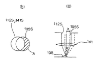
図5(a)は従来の形状測定装置の照明光と反射光との関係を説明する図、図5(b)は図5(a)に示す対物レンズの瞳上における照明光と反射光との関係を説明する図である。
【0012】
対物レンズ141を通った照明光は図5(a)に実線で示したように被検物105の傾いた部分に集光され、反射される。反射光は図5(a)に点線で示したように照明光に対して傾いて対物レンズ141へ戻っていく。
【0013】
ここで、対物レンズ141の瞳上で照明光学系の瞳112S、対物レンズ141の瞳141Sの径が等しい場合を考える(図5(b)参照)。
【0014】
対物レンズ141の瞳141Sの直径φ141は、φ141=2×f×NAで表される。ここで、fは対物レンズの焦点距離、NAは対物レンズの開口数である。
【0015】
また、照明光学系の瞳112Sの直径φ1 12は、φ1 12=β×φ1 3 で表される。ここで、βは照明系の絞りから対物瞳までの倍率であり、φ1 3 は照明系の絞りの直径である。
【0016】
被検物105に傾きがあるとき、反射光105Sは図5(b)に示すように対物レンズ141の瞳141S及び照明光学系の瞳112Sからシフトし、斜線で示した結像に寄与しない成分Aが生じる。ここで、シフト量hは、h=f×sinθで表される。θは図5(a)に示す主光線の反射角度である。
【0017】
そのため、結像に寄与する成分が小さくなり、被検物105の傾いた部分の光量が小さくなって場合によっては検出できなくなり、高さ方向の情報の欠落により撮像面で得られる像に欠けが発生することがある。
【0018】
この発明はこのような事情に鑑みてなされたもので、その課題は被検物の全面で均一な光量を得ることができる形状測定装置を提供することである。
【0019】
【課題を解決するための手段】
前述の課題を解決するため請求項1記載の発明は、光源からの光を被検物に照射する照明光学系と、前記光源から射出された光を前記被検物に集光させる対物レンズと、前記被検物の像を形成する結像レンズと、前記対物レンズの集光位置を光軸方向に相対移動させる集光位置変更手段とを備え、前記対物レンズの瞳径及び前記照明光学系の瞳径は前記対物レンズの瞳上で前記結像レンズの瞳径より大きいことを特徴とする。
【0020】
請求項2記載の発明は、光源からの光を被検物に照射する照明光学系と、前記光源から射出された光を前記被検物に集光させる対物レンズと、前記被検物の像を形成する結像レンズと、前記対物レンズの集光位置を光軸方向に相対移動させる集光位置変更手段とを備え、前記対物レンズの瞳径及び前記結像レンズの瞳径は前記対物レンズの瞳上で前記照明光学系の瞳径より大きいことを特徴とする。
【0021】
請求項3記載の発明は、請求項1又は2記載の形状測定装置において、前記照明光学系の瞳径を変化させることができる第1の瞳径可変手段と、前記結像レンズの瞳径を変化させることができる第2の瞳径可変手段とを備えていることを特徴とする。
【0022】
【発明の実施の形態】
以下、この発明の実施の形態を図面に基づいて説明する。
【0023】
図1はこの発明の第1実施形態に係る形状測定装置の全体構成を示す図である。
【0024】
この形状測定装置1は、光源11と、コレクタレンズ12と、絞り13と、ハーフミラー14と、第1リレーレンズ15aと、ニポウディスク20と、直角ミラー31と、コーナキューブレフレクタ32と、コーナーキューブ駆動装置33と、対物レンズ41と、絞り16と、第2リレーレンズ15bと、アパーチャ18と、ディテクタ50とを備えている。第1リレーレンズ15aと第2リレーレンズ15bとから結像光学系を構成する結像レンズ17が構成される。
【0025】
光源11は照明光を出射する。光源11としては、例えばレーザ、Xeランプ、Heランプ、Neランプ、Arランプ等のアークランプを使用することができる。
【0026】
コレクタレンズ12は照明光学系9を構成し、光源11から出射された光を平行光とする。
【0027】
絞り13は対物レンズ41の瞳と共役な位置に配置され、照明光学系9の瞳径を変化させる。
【0028】
ハーフミラー14は照明光を反射させるが被検物5からの反射光を透過させる。
【0029】
ニポウディスク20にはハーフミラー14で反射され、第1リレーレンズ15aを透過した光を通過させる同じ径の複数のピンホール21が所定の間隔で螺旋状に形成されている。ニポウディスク20はモータ25によって駆動される。
【0030】
直角ミラー31はピンホール21を通過した照明光及び被検物5からの反射光の方向を変える。
【0031】
コーナキューブレフレクタ32は3つの互いに直角の面と直角三角形の斜辺の面を持ったプリズムである。傾斜面に入射した光は3つの面で反射され、反転して入射光に対して平行に傾斜面から出射される。
【0032】
このコーナキューブレフレクタ32をコーナーキューブ駆動装置33によって矢印に示すように移動させることによって被検物5を光軸方向へスキャンすることができるため、被検物5に向かって照明光を選択的に集光させることができる。
【0033】
直角ミラー31、コーナキューブレフレクタ32及びコーナーキューブ駆動装置33で集光位置変更手段が構成される。
【0034】
対物レンズ41はテレセントリックなレンズであり、対物レンズ41を通過して被検物5に照射される光の主光線は光軸に平行となる。
【0035】
絞り16は対物レンズ41の瞳と共役な位置に配置され、結像レンズ17の瞳径を変化させる。
【0036】
アパーチャ18に形成されたピンホール18aは散乱光等の進入を制限する。
【0037】
アパーチャ18を備えるディテクタ50はニポウディスク20のピンホール21が結像する位置に配置され、ディテクタ50にはピンホール21を透過する光の強度に応じた画像が形成される。
【0038】
次に、上記構成の形状測定装置の動作を説明する。
【0039】
光源11から出射された照明光は、コレクタレンズ12によって平行光とされ、絞り13、ハーフミラー14、第1リレーレンズ15aを経て、ニポウディスク20の上面に照射される。
【0040】
照射範囲に含まれる複数のピンホール21を通過した光束はそれぞれ直角ミラー31の上側の反射面31aで反射されてコーナキューブレフレクタ32に入射し、コーナキューブレフレクタ32で複数回反射された後、入射光と平行な照明光として直角ミラー31に戻され、直角ミラー31の下側の反射面31bで反射されて対物レンズ41に入射し、対物レンズ41で被検物5上に集光される。
【0041】
なお、ニポウディスク20の複数のピンホール21をそれぞれ通過した光束はいずれも直角ミラー31及びコーナキューブレフレクタ32で反射され、対物レンズ41で被検物5上の異なる位置にそれぞれ集光される。
【0042】
したがって、被検物5上には光源11からの複数の光束によって複数の光スポットが形成される。
【0043】
被検物5の複数の光スポットからの反射光束はそれぞれ対物レンズ41、直角ミラー31の下側の反射面31b、コーナキューブレフレクタ32、直角ミラー31の上側の反射面31aの順に照明光とは逆方向へ進み、ピンホール21に焦点が結ばれる。
【0044】
このとき、共焦点効果によって光スポットで反射された光だけがピンホール21を通過し、散乱光等はピンホール21に焦点が合わないため、除去される。
【0045】
ピンホール21を通過した反射光束は結像レンズ17に入射する。結像レンズ17に入射した反射光束はそれぞれ第1リレーレンズ15aと第2リレーレンズ15bと絞り16とによりディテクタ50上に集光され、ディテクタ50上に2次元像が形成される。
【0046】
このとき、コーナーキューブ駆動装置33を駆動して得られる焦点位置の異なる複数の画像が図示しない画像処理装置に入力され、入力された画像データから被検物5の立体形状が画像処理装置によって演算される。
【0047】
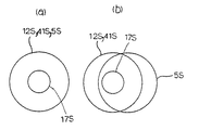
図2はこの発明の第1実施形態に係る形状測定装置の対物レンズの瞳上における対物レンズの瞳径と照明光学系の瞳径と結像レンズの瞳径との関係を示す図であり、図2(a)は被検物の平坦な部分を見た場合であり、図2(b)は被検物の傾いた部分を見た場合である。
【0048】
照明光学系9の瞳12Sの径は絞り13(図1参照)によって対物レンズ41の瞳41Sの径と一致するように絞られている。
【0049】
また、結像レンズ17の瞳17Sの径は絞り16(図1参照)によって対物レンズ41の瞳41Sの径及び照明光学系の瞳12Sの径より小さくなるように絞られている。
【0050】
被検物5(図1参照)の平坦な部分を見た場合、反射光5Sは照明光に対して傾くことなく対物レンズ41に戻るため、反射光5Sは対物レンズ41の瞳41S及び照明光学系9の瞳12Sからシフトしない(図2(a)参照)。
【0051】
被検物5の傾いた部分を見た場合、反射光5Sは照明光に対して傾いて対物レンズ41に戻るため、反射光5Sは対物レンズ41の瞳41S及び照明光学系9の瞳12Sからシフトする(図2(b)参照)。
【0052】
このとき、結像レンズ17の瞳17Sの全域が反射光5Sによってカバーされ、ディテクタ50上に結像される。
【0053】
ここで、被検物からの反射光の対物レンズの光軸から最も離れた最外光線と対物レンズの光軸との角度をθとし、対物レンズの瞳径が2h=fsinθmax で表されるとき、被検物からの反射角度θがθmax 以下である反射光は全て光量損失なく検出することができる。
【0054】
この第1実施形態によれば、被検物5に傾きがある場合であっても従来例のように結像に寄与しない成分が生じないので、被検物5の広い範囲で均一な光量を得ることができる。その結果、被検物5の傾いた部分の光量が小さくなって高さ方向の情報の欠落によりディテクタ50の撮像面で得られる像に欠けが発生することを防止できる。
【0055】
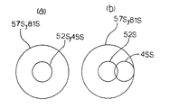
図3はこの発明の第2実施形態に係る形状測定装置の対物レンズの瞳上における対物レンズの瞳径と照明光学系の瞳径と結像レンズの瞳径との関係を示す図であり、図3(a)は被検物の平坦な部分を見た場合であり、図3(b)は被検物の傾いた部分を見た場合である。
【0056】
結像レンズ17の瞳57Sの径は絞り16(図1参照)によって対物レンズ41の瞳81Sの径と一致するように絞られている。
【0057】
また、照明光学系の瞳52Sの径は絞り13(図1参照)によって対物レンズ41の瞳81S及び結像レンズ17の瞳57Sの径より小さくなるように絞られている。
【0058】
被検物5の平坦な部分を見た場合、反射光45Sは照明光に対して傾くことなく対物レンズ41に戻るため、反射光45Sは照明光学系の瞳52Sからシフトしない(図3(a)参照)。
【0059】
被検物5の傾いた部分を見た場合、反射光45Sは照明光に対して傾いて対物レンズ41に戻るため、反射光45Sは照明光学系の瞳52Sからシフトする(図3(b)参照)。
【0060】
このとき、反射光45Sの全域は結像レンズ17の瞳57S及び対物レンズ41の瞳81Sによってカバーされ、ディテクタ50上に結像される。
【0061】
この第2実施形態によれば、第1実施形態と同様の効果を奏する。
【0062】
図4はこの発明の他の実施形態に係る形状測定装置の全体構成を示す図であり、前述の実施形態と共通する部分には同一符号を付してその説明を省略する。
【0063】
この形状測定装置10は、絞り13を駆動して照明光学系9の瞳径を変化させる第1の駆動装置(第1の瞳径可変手段)13Dと、絞り16を駆動して結像レンズ17の瞳径を変化させる第2の駆動装置(第2の瞳径可変手段)16Dと、第1の駆動装置13D及び第2の駆動装置16Dの駆動を制御するコントローラ60とを備えている点で前述の形状測定装置1と相違する。
【0064】
ところで、被検物5の空間周波数の高い成分が多い限界解像に近いときには、σ>1(インコヒーレント)で画像のコントラストが高くなり、被検物の空間周波数の低い成分が多いときには、σ<1(部分的コヒーレント)で画像のコントラストが高くなることが知られている。
【0065】
ここで、σ=(照明光学系の瞳径)/(結像光学系の瞳径)である。
【0066】
したがって、第1実施形態の構成はσ>1(インコヒーレント)であり、第2実施形態の構成はσ<1(部分的コヒーレント)である。
【0067】
コントローラ10は、被検物5の空間周波数の高い成分が多いと判断した場合、第1の駆動装置13D及び第2の駆動装置16Dへ制御信号を出力し、図2に示す関係(照明光学系の瞳径>結像光学系の瞳径)が構築されるように第1の駆動装置13D及び第2の駆動装置16Dを駆動する。
【0068】
また、コントローラ10は、被検物5の空間周波数の低い成分が多いと判断した場合、第1の駆動装置13D及び第2の駆動装置16Dへ制御信号を出力し、図3に示す関係(照明光学系の瞳径<結像光学系の瞳径)が構築されるように第1の駆動装置13D及び第2の駆動装置16Dを駆動する。
【0069】
なお、上記判断は例えば被検物5の面形状の周波数解析に基いて行われる。
【0070】
【発明の効果】
以上に説明したようにこの発明の形状測定装置によれば、被検物の全面で均一な光量を得ることができる。
【図面の簡単な説明】
【図1】図1はこの発明の第1実施形態に係る形状測定装置の全体構成を示す図である。
【図2】図2はこの発明の第1実施形態に係る形状測定装置の対物レンズの瞳上における対物レンズの瞳径と照明光学系の瞳径と結像レンズの瞳径との関係を示す図である。
【図3】図3はこの発明の第2実施形態に係る形状測定装置の対物レンズの瞳上における対物レンズの瞳径と照明光学系の瞳径と結像レンズの瞳径との関係を示す図である。
【図4】図4はこの発明の他の実施形態に係る形状測定装置の全体構成を示す図である。
【図5】図5(a)は従来の形状測定装置の照明光と反射光との関係を説明する図、図5(b)は図5(a)に示す対物レンズの瞳上における照明光と反射光との関係を説明する図である。
【符号の説明】
5 被検物
11 光源
12 コレクタレンズ
13D 第1の駆動装置(第1の瞳径可変手段)
15 第1リレーレンズ
16D 第2の駆動装置(第2の瞳径可変手段)
17 結像レンズ
31 直角ミラー
32 コーナキューブレフレクタ
33 コーナーキューブ駆動装置
41 対物レンズ[0001]
TECHNICAL FIELD OF THE INVENTION
The present invention relates to a shape measuring device, and more particularly to a shape measuring device suitable for measuring the height of a test object.
[0002]
[Prior art]
[0003]
[Patent Document]
Japanese Patent Application Laid-Open No. 2002-13917
2. Description of the Related Art As a conventional shape measuring device, a device for measuring a three-dimensional shape of a minute object using a confocal optical system is known.
[0005]
This shape measuring device includes a light source, a Nipkow disc, an objective lens, a focusing position changing mechanism for relatively moving the focusing position of the objective lens in the optical axis direction, an imaging lens, and an imaging element. The light condensing position changing mechanism includes a right-angle mirror, a corner cube prism, and a driving unit that drives the corner cube prism.
[0006]
Illumination light emitted from the light source passes through a collector lens, is reflected by a half mirror, and is irradiated on the upper surface of the Nipkow disc. Of the illumination light, only the illumination light that has passed through the pinhole reaches the focusing position changing mechanism, and is focused on the focal plane of the test object by the objective lens.
[0007]
The reflected light from the test object proceeds to the objective lens and the focusing position changing mechanism, and the objective lens focuses on the pinhole of the Nipkow disc. At this time, only light reflected on the focal plane of the test object by the confocal effect passes through the pinhole.
[0008]
After passing through the half mirror, the light beam passing through the pinhole is imaged on the imaging surface of the imaging device by the imaging lens.
[0009]
At this time, the optical path length from the pinhole to the test object is continuously changed by the condensing position changing mechanism, and an image of the test object is acquired at each focal position.
[0010]
[Problems to be solved by the invention]
However, this shape measuring apparatus has the following problems when observing a tilted portion (a portion tilted with respect to the optical axis) of the test object.
[0011]
FIG. 5A is a diagram for explaining the relationship between the illumination light and the reflected light of the conventional shape measuring device, and FIG. 5B is a diagram illustrating the relationship between the illumination light and the reflected light on the pupil of the objective lens shown in FIG. FIG.
[0012]
The illumination light passing through the
[0013]
Here, a case is considered where the
[0014]
Diameter phi 141 of the pupil 141S of the
[0015]
The diameter phi 1 12 pupil 112S of the illumination optical system is represented by φ 1 12 = β × φ 1 3. Here, beta is the ratio of the aperture of the illumination system to the objective pupil, phi 1 3 is the diameter of the aperture of the illumination system.
[0016]
When the
[0017]
Therefore, the component contributing to image formation becomes small, and the amount of light in the inclined portion of the
[0018]
The present invention has been made in view of such circumstances, and an object thereof is to provide a shape measuring device capable of obtaining a uniform light amount over the entire surface of a test object.
[0019]
[Means for Solving the Problems]
In order to solve the above-mentioned problem, the invention according to
[0020]
The invention according to claim 2 is an illumination optical system that irradiates the test object with light from a light source, an objective lens that condenses the light emitted from the light source on the test object, and an image of the test object. And a focusing position changing means for relatively moving the focusing position of the objective lens in the optical axis direction, wherein the pupil diameter of the objective lens and the pupil diameter of the imaging lens are the same as those of the objective lens. Is larger than the pupil diameter of the illumination optical system on the pupil.
[0021]
According to a third aspect of the present invention, in the shape measuring apparatus according to the first or second aspect, a first pupil diameter varying unit capable of changing a pupil diameter of the illumination optical system, and a pupil diameter of the imaging lens are set. And a second pupil diameter varying means capable of changing the pupil diameter.
[0022]
BEST MODE FOR CARRYING OUT THE INVENTION
Hereinafter, embodiments of the present invention will be described with reference to the drawings.
[0023]
FIG. 1 is a view showing an entire configuration of a shape measuring apparatus according to a first embodiment of the present invention.
[0024]
The
[0025]
The
[0026]
The
[0027]
The
[0028]
The
[0029]
A plurality of
[0030]
The right-
[0031]
The
[0032]
The
[0033]
The
[0034]
The
[0035]
The
[0036]
The
[0037]
The
[0038]
Next, the operation of the shape measuring apparatus having the above configuration will be described.
[0039]
Illumination light emitted from the
[0040]
The luminous fluxes that have passed through the plurality of
[0041]
The light beams that have passed through the plurality of
[0042]
Therefore, a plurality of light spots are formed on the
[0043]
The reflected luminous fluxes from the plurality of light spots of the
[0044]
At this time, only the light reflected by the light spot due to the confocal effect passes through the
[0045]
The reflected light flux passing through the
[0046]
At this time, a plurality of images having different focal positions obtained by driving the corner
[0047]
FIG. 2 is a diagram showing the relationship between the pupil diameter of the objective lens, the pupil diameter of the illumination optical system, and the pupil diameter of the imaging lens on the pupil of the objective lens of the shape measuring apparatus according to the first embodiment of the present invention; FIG. 2A shows a case where a flat portion of the test object is viewed, and FIG. 2B shows a case where a tilted portion of the test object is viewed.
[0048]
The diameter of the pupil 12S of the illumination
[0049]
The diameter of the pupil 17S of the
[0050]
When the flat part of the test object 5 (see FIG. 1) is viewed, the reflected light 5S returns to the
[0051]
When the inclined part of the
[0052]
At this time, the entire area of the pupil 17S of the
[0053]
Here, the angle between the optical axis of the objective lens and the outermost ray of the reflected light from the test object farthest from the optical axis of the objective lens is θ, and the pupil diameter of the objective lens is represented by 2h = f sin θ max. At this time, all the reflected light having a reflection angle θ from the test object equal to or smaller than θ max can be detected without loss of light amount.
[0054]
According to the first embodiment, even when the
[0055]
FIG. 3 is a diagram showing the relationship between the pupil diameter of the objective lens, the pupil diameter of the illumination optical system, and the pupil diameter of the imaging lens on the pupil of the objective lens of the shape measuring apparatus according to the second embodiment of the present invention; FIG. 3A shows a case where the flat part of the test object is seen, and FIG. 3B shows a case where the inclined part of the test object is seen.
[0056]
The diameter of the pupil 57S of the
[0057]
The diameter of the pupil 52S of the illumination optical system is reduced by the aperture 13 (see FIG. 1) so as to be smaller than the diameter of the pupil 81S of the
[0058]
When the flat part of the
[0059]
When the inclined part of the
[0060]
At this time, the entire area of the reflected light 45S is covered by the pupil 57S of the
[0061]
According to the second embodiment, the same effects as those of the first embodiment can be obtained.
[0062]
FIG. 4 is a view showing the overall configuration of a shape measuring apparatus according to another embodiment of the present invention. The same reference numerals are given to parts common to the above-described embodiments, and the description thereof will be omitted.
[0063]
The
[0064]
By the way, when the resolution is close to the limit resolution where many components having a high spatial frequency of the
[0065]
Here, σ = (pupil diameter of illumination optical system) / (pupil diameter of imaging optical system).
[0066]
Therefore, the configuration of the first embodiment has σ> 1 (incoherent), and the configuration of the second embodiment has σ <1 (partially coherent).
[0067]
When the
[0068]
When the
[0069]
The above determination is performed based on, for example, a frequency analysis of the surface shape of the
[0070]
【The invention's effect】
As described above, according to the shape measuring apparatus of the present invention, a uniform light amount can be obtained over the entire surface of the test object.
[Brief description of the drawings]
FIG. 1 is a view showing an entire configuration of a shape measuring apparatus according to a first embodiment of the present invention.
FIG. 2 shows the relationship between the pupil diameter of the objective lens, the pupil diameter of the illumination optical system, and the pupil diameter of the imaging lens on the pupil of the objective lens of the shape measuring apparatus according to the first embodiment of the present invention. FIG.
FIG. 3 shows the relationship between the pupil diameter of the objective lens, the pupil diameter of the illumination optical system, and the pupil diameter of the imaging lens on the pupil of the objective lens of the shape measuring apparatus according to the second embodiment of the present invention. FIG.
FIG. 4 is a diagram showing an overall configuration of a shape measuring apparatus according to another embodiment of the present invention.
5 (a) is a view for explaining the relationship between illumination light and reflected light of a conventional shape measuring device, and FIG. 5 (b) is illumination light on a pupil of an objective lens shown in FIG. 5 (a). FIG. 4 is a diagram for explaining the relationship between the light and reflected light.
[Explanation of symbols]
5
15
17
Claims (3)
前記光源から射出された光を前記被検物に集光させる対物レンズと、
前記被検物の像を形成する結像レンズと、
前記対物レンズの集光位置を光軸方向に相対移動させる集光位置変更手段とを備え、
前記対物レンズの瞳径及び前記照明光学系の瞳径は前記対物レンズの瞳上で前記結像レンズの瞳径より大きいことを特徴とする形状測定装置。An illumination optical system that irradiates the test object with light from a light source;
An objective lens for condensing light emitted from the light source on the test object,
An imaging lens for forming an image of the test object,
Light-condensing position changing means for relatively moving the light-condensing position of the objective lens in the optical axis direction,
A pupil diameter of the objective lens and a pupil diameter of the illumination optical system are larger than a pupil diameter of the imaging lens on the pupil of the objective lens.
前記光源から射出された光を前記被検物に集光させる対物レンズと、
前記被検物の像を形成する結像レンズと、
前記対物レンズの集光位置を光軸方向に相対移動させる集光位置変更手段とを備え、
前記対物レンズの瞳径及び前記結像レンズの瞳径は前記対物レンズの瞳上で前記照明光学系の瞳径より大きいことを特徴とする形状測定装置。An illumination optical system that irradiates the test object with light from a light source;
An objective lens for condensing light emitted from the light source on the test object,
An imaging lens for forming an image of the test object,
Light-condensing position changing means for relatively moving the light-condensing position of the objective lens in the optical axis direction,
The pupil diameter of the objective lens and the pupil diameter of the imaging lens are larger than the pupil diameter of the illumination optical system on the pupil of the objective lens.
前記結像レンズの瞳径を変化させることができる第2の瞳径可変手段と
を備えていることを特徴とする請求項1又は2記載の形状測定装置。First pupil diameter varying means capable of changing a pupil diameter of the illumination optical system;
The shape measuring apparatus according to claim 1, further comprising a second pupil diameter varying unit that can change a pupil diameter of the imaging lens.
Priority Applications (1)
| Application Number | Priority Date | Filing Date | Title |
|---|---|---|---|
| JP2002322026A JP2004156981A (en) | 2002-11-06 | 2002-11-06 | Shape measuring instrument |
Applications Claiming Priority (1)
| Application Number | Priority Date | Filing Date | Title |
|---|---|---|---|
| JP2002322026A JP2004156981A (en) | 2002-11-06 | 2002-11-06 | Shape measuring instrument |
Publications (2)
| Publication Number | Publication Date |
|---|---|
| JP2004156981A true JP2004156981A (en) | 2004-06-03 |
| JP2004156981A5 JP2004156981A5 (en) | 2005-10-27 |
Family
ID=32802330
Family Applications (1)
| Application Number | Title | Priority Date | Filing Date |
|---|---|---|---|
| JP2002322026A Pending JP2004156981A (en) | 2002-11-06 | 2002-11-06 | Shape measuring instrument |
Country Status (1)
| Country | Link |
|---|---|
| JP (1) | JP2004156981A (en) |
-
2002
- 2002-11-06 JP JP2002322026A patent/JP2004156981A/en active Pending
Similar Documents
| Publication | Publication Date | Title |
|---|---|---|
| JP3440465B2 (en) | Multi-slit scanning imaging device | |
| US6522443B1 (en) | High-resolution writing using beams and lenses rotating at equal or double speed | |
| JP2006295914A5 (en) | ||
| JP5268061B2 (en) | Board inspection equipment | |
| JPH04171415A (en) | Long-focus depth high-resolution irradiating optical system | |
| JP6552043B2 (en) | Sheet illumination microscope | |
| JPH10161195A (en) | Autofocusing method and device | |
| JP3611755B2 (en) | Three-dimensional shape detection method and apparatus, and confocal detection apparatus | |
| JP3509088B2 (en) | Optical device for three-dimensional shape measurement | |
| US20030058455A1 (en) | Three-dimensional shape measuring apparatus | |
| JP2004102032A (en) | Scanning type confocal microscope system | |
| JP2004156981A (en) | Shape measuring instrument | |
| JP2008261829A (en) | Surface measuring device | |
| JP3113232B2 (en) | microscope | |
| JP2001311874A (en) | Optical scanner and tomographic image acquiring device using the same | |
| JP2002148521A (en) | Microscope | |
| JP2001324314A (en) | Measuring instrument | |
| JP4066629B2 (en) | 3D shape measurement optical system | |
| JPH04177742A (en) | Lead height measuring instrument | |
| JPH11153513A (en) | Optical view-field angel measuring device | |
| JP3279815B2 (en) | Displacement / tilt detection method and automatic focusing device using the same | |
| JP2830915B2 (en) | Particle size distribution measuring device | |
| JPH1048527A (en) | Image rotator device and scanning optical microscope | |
| JPH10122831A (en) | Surface inspection equipment | |
| JP2002008249A (en) | Optical axis adjusting machine for optical pickup device |
Legal Events
| Date | Code | Title | Description |
|---|---|---|---|
| A521 | Written amendment |
Free format text: JAPANESE INTERMEDIATE CODE: A523 Effective date: 20050707 |
|
| A621 | Written request for application examination |
Free format text: JAPANESE INTERMEDIATE CODE: A621 Effective date: 20051031 |
|
| A131 | Notification of reasons for refusal |
Free format text: JAPANESE INTERMEDIATE CODE: A131 Effective date: 20071211 |
|
| A02 | Decision of refusal |
Free format text: JAPANESE INTERMEDIATE CODE: A02 Effective date: 20080408 |