JP2004145496A - Maintenance supporting method for equipment and facility - Google Patents
Maintenance supporting method for equipment and facility Download PDFInfo
- Publication number
- JP2004145496A JP2004145496A JP2002307780A JP2002307780A JP2004145496A JP 2004145496 A JP2004145496 A JP 2004145496A JP 2002307780 A JP2002307780 A JP 2002307780A JP 2002307780 A JP2002307780 A JP 2002307780A JP 2004145496 A JP2004145496 A JP 2004145496A
- Authority
- JP
- Japan
- Prior art keywords
- equipment
- maintenance
- time
- information
- calculated
- Prior art date
- Legal status (The legal status is an assumption and is not a legal conclusion. Google has not performed a legal analysis and makes no representation as to the accuracy of the status listed.)
- Pending
Links
Images


Classifications
-
- Y—GENERAL TAGGING OF NEW TECHNOLOGICAL DEVELOPMENTS; GENERAL TAGGING OF CROSS-SECTIONAL TECHNOLOGIES SPANNING OVER SEVERAL SECTIONS OF THE IPC; TECHNICAL SUBJECTS COVERED BY FORMER USPC CROSS-REFERENCE ART COLLECTIONS [XRACs] AND DIGESTS
- Y04—INFORMATION OR COMMUNICATION TECHNOLOGIES HAVING AN IMPACT ON OTHER TECHNOLOGY AREAS
- Y04S—SYSTEMS INTEGRATING TECHNOLOGIES RELATED TO POWER NETWORK OPERATION, COMMUNICATION OR INFORMATION TECHNOLOGIES FOR IMPROVING THE ELECTRICAL POWER GENERATION, TRANSMISSION, DISTRIBUTION, MANAGEMENT OR USAGE, i.e. SMART GRIDS
- Y04S10/00—Systems supporting electrical power generation, transmission or distribution
- Y04S10/50—Systems or methods supporting the power network operation or management, involving a certain degree of interaction with the load-side end user applications
Landscapes
- Management, Administration, Business Operations System, And Electronic Commerce (AREA)
- Testing And Monitoring For Control Systems (AREA)
Abstract
Description
【0001】
【発明の属する技術分野】
本発明は、機器設備の保守支援方法に係り、特に発電設備に好適な保守支援方法に関する。
【0002】
【従来の技術】
従来の聞き設備の保守支援方法の例が、非特許文献1に記載されている。この非特許文献1においては、ガスタービンを有するコンバインドサイクルにおいて、定義した等価運転時間に基づいてガスタービンの保守間隔を設定している。この等価運転時間は、負荷を一定にして所定時間運転した後にガスタービンに生ずる損傷と、起動停止回数や負荷変動回数および異常発生による停止回数等の負荷変動に起因する損傷とを比較し、これら負荷変動に起因する損傷が生じるまでの時間を一定負荷運転の経過時間に換算した時間である。この換算係数を、機器の運転当初は経験に基づいて決定し、その後点検の際に実機の機器設備の損傷状態と比較して、この換算係数を補正している。
【0003】
従来の機器設備の保守方法の他の例が、非特許文献2に記載されている。この文献に記載の保守方法では、損失関数を用いて機器を保守保全している。損失関数により定義される最適予防保全式から、予防保全における最適点検間隔と最適保全限界を求め、保守保全に係るコストを最小化している。その際、最適予防保全式は、故障したときの損失や、平均故障間隔、定期点検のコスト、現行点検間隔、機能限界、現行保全限界、保全限界を超えたときの保全費用をパラメータとして表わされる。
【0004】
なお、損失関数を用いてプラントの運転制御を支援する方法が、特許文献1に記載されている。この特許文献では、損失関数とプラントの異常事象の発生確率とから、異常事象における損失を算出している。そして、統計的決定理論に基づいて期待値を最小化し、異常発生時のプラントを正常に復旧させている。
【特許文献1】
特開平8−101710号公報
【非特許文献1】
前田一郎 「コンバインドサイクルの運用実績と信頼性向上 九州電力新大分発電所」日本ガスタービン学会誌、Vol.24、No.93、(1996)、 第23〜26頁
【非特許文献2】
田口玄一著、「品質工学講座(2) 製造段階の品質工学」、日本規格協会、(1989)(特にその第194〜214頁)
【0005】
【発明が解決しようとする課題】
上記非引用文献1に記載の等価運転時間を用いた機器の保守方法では、実際の機器の損傷状況に基づいて等価運転時間を求めるので寿命予測の精度は高くなるものの、定期点検時等にしか機器の状況を把握しておらず、時々刻々変化する損傷状態を診断することが困難である。また、運転パターンによる等価運転時間が変化することについては考慮されていない。
【0006】
非特許文献2に記載の保守方法では、機器の機能の劣化が線形的で平均的に進行することを仮定しており、実機に生ずる機能の劣化を必ずしも再現してはいない。さらに、最適予防保全式を作成した後に機器の仕様環境が変化する場合については、この非特許文献2ではほとんど考慮されていない。また、特許文献に記載1の保守方法では、損失関数を安全性に関する損失と運転制御に関する方法に限定して使用している。そのため、プラントが周囲の状況の変化に影響されやすいガスタービン設備等を保守することについては、考慮されておらず、損失関数を用いた運転保守支援方法が必ずしも有効には機能していなかった。
【0007】
本発明は上記従来技術の不具合に鑑みなされたものであり、その目的は、プラントや機器設備の予防保全を合理化することにある。本発明の他の目的は、予防保全の信頼性を向上させることにある。
【0008】
【課題を解決するための手段】
上記目的を達成するための本発明の特徴は、機器設備ごとに定義された損失関数を用いて機器設備を保守支援する支援方法であって、機器設備を遠隔監視して得られた時間とともに変化する機器設備の情報に基づいて時間とともに変化する損失関数を演算し、この演算した損失関数に基づいて最適点検間隔と最適保全限界の少なくともいずれかを演算し、演算した最適点検間隔または最適保全限界に基いて機器設備の保守予定時期を更新することにある。
【0009】
そしてこの特徴において、損失関数が、時間とともに変化する複数の予防保全パラメータを有するのがよく、遠隔監視により得られた機器設備の情報と、機器設備の所有者と機器設備のメンテナンス事業者とインターネットと情報提供者の少なくともいずれから提供された機器設備の情報との少なくとも一方を用いて時間とともに変化する損失関数を演算するのがよい。
【0010】
また好ましくは、機器設備の供用前に設定した保守予定時期を、この保守予定時期より前の時点で求めた損失関数により更新するものであり、機器設備の供用前に設定した保守予定時期より前の時点で、機器設備が備える部品の機能予測値を求め、この求めた機能予測値が機器設備の供用前に設定した機能限界変化値と異なるときに機能限界の予測式を更新するようにしてもよい。さらに、損失関数を間隔をおいて時々刻々求め、この時々刻々求めた損失関数に基いて、機器設備の保守予定時期を更新するようにしてもよい。
【0011】
上記目的を達成する本発明の他の特徴は、機器設備ごとに定義された損失関数を用いて機器設備を保守支援する支援方法であって、損失関数は機器設備を遠隔監視して得られた情報を含む複数のパラメータを有し、このパラメータ値を遠隔監視情報から定めて損失関数を演算し、この演算した損失関数に基づいて最適点検間隔と最適保全限界の少なくともいずれかを演算し、演算した最適点検間隔または最適保全限界に基いて機器設備の保守予定時期を更新するものである。
【0012】
そしてこの特徴において、複数のパラメータは、機器設備が故障した際の損失と、平均故障間隔と、現行の点検間隔と、機能限界と、現行の保全限界と、保全限界を超えた際の保全費との少なくともいずれかを含み、損失関数が含むパラメータの値を逆問題解析手法または負荷対応等価運転時間法により定めることが望ましい。
【0013】
さらに上記特徴において、パラメータ値を定める方法が逆問題解析手法のときには、遠隔監視により得られた情報に基づいて機器設備の運用状態を推定し、この運用状態の推定情報に基づいて、機器設備が備える部品の損傷に関する応答曲面を参照して機器設備の損傷を推定するのがよく、パラメータ値を定める方法が負荷対応等価運転時間法のときには、機器設備の遠隔監視により得られる情報に基づいて、機器設備の劣化損傷モード毎に算出した負荷対応等価運転時間を参照して機器設備の損傷を推定するのがよい。
【0014】
さらに、上記各特徴において機器設備がガスタービンを含むコンバインドサイクルの場合に好適である。
【0015】
【発明の実施の形態】
以下、本発明に係る機器設備の保守支援システムの実施例を、図面を参照しながら説明する。図1は本発明の基本概念の模式図であり、設備と情報の流れを示している。本保守支援システムは、コンバインドサイクルに適用した場合を例にしている。保守支援装置101は、記憶媒体を有する演算装置(以下、演算装置と呼ぶ)102を備えている。保守支援装置101は、保守の対象であるプラントまたは機器設備(以下、機器設備と呼ぶ)103と通信設備109により接続されている。通信設備109として、インターネットや専用回線、無線回線を用いることができる。機器設備103には、運転状態を監視するセンサ104が設置されており、センサ104が検出した機器設備103の情報は、保守支援装置101内の演算装置102に送られる。
【0016】
保守支援装置101を用いて、機器設備103を保守計画する従事者は、機器設備103のメンテナンス会社107と、機器設備の所有者106と、インターネット109からの情報提供者またはその他の手段の情報提供者108の少なくともいずれかから、機器設備103の予防保全に関する情報を得る。演算装置102では、この得られた予防保全に関する情報を用いて、予め定義された損失関数に基づいて最適予防保全式を作成し、予防保全に伴う損失を算出する。そして、予防保全に伴う損失を用いて、最適点検間隔や最適保全限界110の少なくともいずれかを算出する。
【0017】
機器設備103に設置されたセンサ104は、機器設備に関するプロセス情報と、運転情報と、メンテナンス情報の少なくともいずれかを検出する。機器設備103をガスタービンコンバインド発電設備としたときのプロセス情報と運転情報とメンテナンス情報の例を、図2に示す。
【0018】
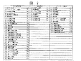
プロセス情報は、a1〜a30で記号付けられた30個の温度情報や変位情報等の、物理量を含んでいる。運転情報は、b1〜b8で記号付けられた運転時間等の情報を含んでいる。メンテナンス情報は、c1〜c15で記号付けられた損傷情報と修理情報等を含んでいる。損失の算出には、図2で示したプロセス情報と運転情報とメンテナンス情報の全てまたは一部を用いる。なお、プロセス情報を、主として機器設備103に設けたセンサ104から得ている。運転情報を、機器設備103が備える制御盤から得ている。さらにメンテナンス情報は、機器設備103の所有者106やメンテナンス会社107から得ている。
【0019】
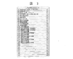
予防保全の従事者は、機器設備103の所有者106とメンテナンス会社107と情報提供会社108とインターネット109の情報提供者から、最適予防保全式を構成する損失関数に使用される各種パラメータ(以下、予防保全パラメータと呼ぶ)に係る情報を取得する。この予防保全パラメータの例を、図3に示す。予防保全パラメータは、d1〜d30で記号付けられた各種料金等の経済指標を示すものを含んでいる。損失関数を決めるときは、図3で示す全てのパラメータまたは一部のパラメータを用いる。
【0020】
図4に、ガスタービンコンバインド発電設備のブロック図を示す。ガスタービン発電設備1は、ガスタービン圧縮機2と燃焼器3とタービン4とを有するガスタービン4bと、ガスタービン4bが駆動する発電機5とを備えている。このコンバインド発電設備1では、排熱回収ボイラ6と蒸気タービン7と蒸気タービン7が駆動する発電機8と復水器9も備えている。
【0021】
圧縮機2、燃焼器3、タービン4、発電機5、8、排熱回収ボイラ6、蒸気タービン7および復水器9等の主要機器とその他の補機には、各機器の状態を監視する各種センサ10i(i=a〜h,…)が取り付けられている。センサ10i(i=a〜h,…)は、ケーブル10xを用いて運転監視装置11に接続されており、センサ10i(i=a〜h,…)が検出したプロセス情報は運転監視装置11で処理または保管される。
【0022】
運転監視装置11は、センサ10i(i=a〜h,…)が検出したプロセス情報とガスタービン発電設備1やガスタービンの運転制御装置4aから受信した運転情報を、運転監視装置側通信機器12、通信回線13および機器管理装置側通信機器14を順に介して機器管理装置15に送る。運転監視装置11と運転監視装置側通信機器12は、同一の電子計算機(コンピュータ)でもよい。機器管理装置側通信機器14を、機器管理装置15の内部に設けてもよい。この図4に示した機器管理装置15は、機能上はプラント1の保守支援を行う装置であり、図1における保守支援装置101に対応する。通信回線13がインターネット回線のときには、データのセキュリティを考慮して運転監視装置側通信機器12と機器管理装置側通信機器14の間を、インターネット用ファイヤーウォールを介して接続する。
【0023】
機器管理装置15には、損傷に関するデータベース17と損傷に関する知識ベース18とを有する解析サーバ16が備えられている。このサーバ16とWWWサーバ19が接続されており、これら2つのサーバ16、19には、インターネット回線13を通じて得られたガスタービン発電装置1の状態量が入力される。さらにこの状態量は、LAN22を介してwwwブラウザ21、22により参照可能になっている。なお、インターネット13を介して、多数のプラント23a、23b、…の情報に、ガスタービン発電設備の情報と同様にアクセス可能となっている。
【0024】
センサ10i(i=a〜h,…)は、図2に示したプロセス情報の中の、排ガス温度a1と吐出空気温度a3と入口空気温度a7の温度情報、吐出空気圧力a4と入口空気圧力a8の圧力情報、軸受振動a12と軸振動a13の振動情報等の情報を計測する。これらの計測されたプロセス情報または状態量は、運転監視装置11に送られる。
【0025】
次に実際の機器設備103の予防保全に際して、機器設備103の損失を算出する手法について説明する。機器設備103の損失は、(式1)を用いて算出される。
【0026】
L(t)=f(A(t),B(t),C(t),CL(t),D(t),DL(t),l(t),n(t),ui(t),…) ……(式1)
ここで、損失関数で考慮するパラメータは、
A(t):機器設備故障した際の損失(円)
B(t):定期点検のコスト(円)
C(t):保全(交換)のコスト(円)
CL(t):保全限界を超えた際の保全費(円)
D(t):現行保全限界(%,き裂長さなど)
DL(t):機能限界(%,き裂長さなど)
l(t):タイムラグ(時間/年/日)
n(t):現行点検間隔(時間/年/日)
ui(t):平均故障間隔(時間/年/日)
であり、最適化するパラメータは、
n0(t):最適点検間隔(時間/年/日)
DU(t):最適保全限界(%,き裂長さなど)である。
【0027】
(式1)の左辺のL(t)は、機器設備において生ずる損失関数の期待値である。最適化するパラメータは、最適点検間隔n0(t)と最適保全限界DU(t)の少なくともいずれかである。上式のA(t)、B(t)、C(t)、CL(t)、D(t)、DL(t)、l(t)、n(t)、ui(t)、n0(t)、DU(t)は、それぞれ図3中のd1〜d11に対応する。
【0028】
損失関数L(t)を、故障したときの損失A(t)、定期点検のコストB(t)、保全または交換時のコストC(t)、保全限界を超えた場合の保全コストCL(t)、タイムラグl(t)および現行保全限界D(t)の二乗に比例し、機能限界DL(t)の二乗、現行点検間隔n(t)および平均故障間隔ui(t)に反比例するように決定する。損失関数L(t)の一例を(式2)に、最適点検間隔n0(t)の一例を(式3)に、最適保全限界DU(t)の一例を(式4)に示す。
【0029】
【数1】

(式3)では、最適点検間隔n0(t)は、平均故障間隔ui(t)に比例し、定期点検のコストB(t)を故障時の損失A(t)で除した値の平方根に比例する。最適保全限界DU(t)は、保全コストCL(t)を故障時のコストA(t)で除した値の4乗根と機能限界DL(t)に比例する。従来、最適時間間隔や最適保全限界は予め定められた値であったが、本実施例においてはこれらを時間の関数として、時々刻々算出している。これにより、迅速かつ最も現状に適した最適化が可能になっている。
【0031】
予防保全パラメータの中で、故障したときの損失A(t)、定期点検のコストB(t)、保全または交換に要するコストC(t)、保全限界を超えたときの保全コストCL(t)は、対象とする機器設備103の保守コストに関係する。これらの保守コストを、機器設備所有者106、メンテナンス会社107、情報提供会社108およびインターネット109での情報提供者から提供される情報の少なくともいずれかを用いて算出する。
【0032】
タイムラグl(t)および現行点検間隔n(t)、平均故障間隔ui(t)は、点検に要する時間に関係する。これらの時間を、機器設備所有者106およびメンテナンス会社107、情報提供会社108から提供された情報の少なくともいずれかをを用いて算出する。現行保全限界D(t)と機能限界DL(t)は、機器設備の状況に関係する。これらの情報は、主に機器設備103の遠隔監視設備11の情報に基づいて算出する。
【0033】
図4に示したシステムにおいて、遠隔監視を用いて機器設備103の機能限界を把握して損失関数を算出するフローチャートを、図5に示す。損失関数L(t)の演算を、ステップ101で開始すると、運転監視装置11が予防保全パラメータと機器設備から送信されたセンサ信号のデータを収集し始める(ステップs102)。収集したデータの中で、機器設備103の損傷診断データについてステップs103で損傷診断し、ステップs104で機器設備103の機能の現在値を推定する。
【0034】
推定した機器設備103の現状値から、ステップs105において現状の機能限界の設定値に達するまでの時間を推定する。機能限界に達する時間を推定したら、この情報を用いてステップs106において故障間隔と点検間隔を見直す。
【0035】
機器設備103の損傷診断以外の収集データを用いて、予防保全に係る損失を算出する。ステップs102で収集したデータとステップs106で見直した故障間隔と点検間隔を用いて損失関数を定義し、ステップs107において予防保全に伴う損失を求める。そして、ステップs108において現在の損失L(t)と過去の損失L(t0)とを比較する。現在の損失L(t)が過去の損失L(t0)より小さい場合は、見直した故障間隔と点検間隔が有効であることを意味するので、今回求めた損失を新たな設定損失として、故障間隔と点検間隔を置き換える(ステップs110)。逆に、現在の損失L(t)が過去の損失L(t0)より大きい場合は、見直し前の故障間隔と点検間隔の方が適していることを示している。そこで、設定損失を過去の設定損失に戻し、故障間隔と点検間隔を置き換える(ステップs109)。これらの手順を踏んだ後に、損失関数の算定を終了する(ステップs111)。
【0036】
機器設備103の最適点検間隔の算出方法を、図6を用いて説明する。図6の横軸は経過時間を示す。機器設備103の点検間隔を決定する場合、該当する機器設備103の運転開始t0前に、損失関数を用いて損失L(t0)を算出する。そして、この算出した損失L(t0)を用いて、保守予定時期t1と最適点検間隔(t1−t0)を算出する。この損失の計算においては、運転開始t0時点で取得可能な機器設備103の遠隔監視情報と、機器設備103のメンテナンス事業者とインターネットと機器設備103の所有者とその他の情報提供者との少なくともいずれかから提供される予防保全パラメータの情報とを用いる。
【0037】
機器設備103を運転する当初は、保守予定時期t1まで運転することを目標にする。次で、保守予定時期t1に達する前の機器設備103の供用中の時期tpに、再び損失関数を用いて損失L(tp)を算出し(図5のステップs108参照)、更新すべき保守予定時期t2と最適点検間隔(t2−t0)を算出する。この時点で機器設備103を現在時間tpまで運転しているから、次回の点検時期までの残り期間は(t2−tp)となる。
【0038】
機器設備103の運転開始前に算出した保守予定時期t1と機器設備103を供用中に算出した保守予定時期t2とが一致したら、次回の保守予定時期は、当初計画の時期である(t1−t0)時間経過後で良い。これに対して、保守予定時期t1と保守予定時期t2とが異っていたら、損失の少ない方の保守予定時期に保守予定時期を更新する。なお、機器設備103の運転者は、必ずしも損失の少ない方に保守予定時期を更新しなくてもよい。例えば、急な機器設備の停止が使用者に多大な損失を与える場合等、ある程度の損失を覚悟してでもプラントを運転する必要がある場合には、運転を続行する。
【0039】
機器設備103の損失を算出するときに用いる予防保全パラメータの中で、機能限界と保全限界は機器設備103を構成する部品の損傷状態に大きく依存する。そこで、機器設備103に設置された各種センサ10i(i=a〜h,…)からの情報および運転情報、メンテナンス情報から、機器設備103の機能限界と保全限界を推定する。推定した機能限界と保全限界を用いて、機器設備103の損失を算出する。
【0040】
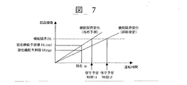
機能限界と保守予定時期の関係を、図7により説明する。図7の横軸は機器設備103の運転時間を示し、縦軸はこの機器設備103に用いる各種部品の損傷程度を示す。機器設備103には、それぞれ機能限界DLが設定されている。機器設備103の運転開始前に、運転時間に対する部品の損傷の進行度を機能限界変化(当初予測)として把握しておく。その際、保守予定時期をt1に初期設定する。機器設備103を運転して現在時間tpに達したときの機能予測値を、遠隔監視データを用いて算出する。算出した機能予測値が、当初予測の現在機能予測値DL1(tp)ではなく、それより損傷の少ない現在機能予測値DL(tp)になったとする。損傷の進行が当初の予測より遅いものと考えられので、保守予定時期をt2まで延ばす。これに伴い、予防保全パラメータの平均故障間隔ui(時間/年/日)を見直し、部品の実際の損傷状態が機器設備103全体の損失に与える影響を算出する。なお、保守予定時期の更新に用いるデータとして、遠隔監視により得られる他の予防保全パラメータを用いてもよい。
【0041】
遠隔監視による機器設備103の損傷の算出方法を、図8を用いて説明する。機器設備103はガスタービン発電設備であり、損傷を算出するのは高温部品である。図8は、損傷診断と寿命診断の流れを示す図である。ステップs1は損傷を診断されるガスタービン側の手順を示し、ステップs2は損傷を診断する側を示している。
【0042】
ステップs3において、ガスタービンに取り付けた各種センサからの信号を取得する。この取得されたセンサ信号から、ステップs4において、予め作成しておいたセンサ信号と高温部品の温度、応力、ひずみとの関係式を用いて、各高温部品の温度と応力とひずみを算出する。算出した温度と応力とひずみスとを用いて、テップs5において、材料の損傷率の変化を求める。
【0043】
ステップs6において、ガスタービンの運転情報を取得する。この運転情報とステップs5において求めた損傷率の変化とを用いて、ステップs7において材料のクリープ損傷と熱疲労損傷を算出する。算出したクリープ損傷と熱疲労損傷から、ステップs8において等価運転時間を算出する。ここで、等価運転時間は、起動停止回数や負荷変動回数、異常発生による停止回数といった負荷の変動があって生じた損傷が、実際に負荷一定で運転したガスタービンに生じた損傷と等価になったときに、負荷一定運転したガスタービンの運転に費やした時間である。
【0044】
算出した等価運転時間や損傷データを、ガスタービンの運用者側に提供する(ステップs9)。この損傷情報に基づいて、ガスタービンの運用者は運転計画情報を作成する(ステップs10)。ガスタービンの運用者から提供された運転計画情報と、ステップs8で算出した等価運転時間とから、余寿命を算出する(ステップs11)。そして算出した余寿命の情報をガスタービンの運用者側に提供する(ステップs12)。なおステップs9及びステップs12の損傷情報と余寿命情報を、必ずしもガスタービンの運用者に提供する必要はない。
【0045】
ステップs4において用いたガスタービンのセンサ信号と温度、応力、ひずみとの関係式の求め方を、(式5)と(式6)を用いて説明する。ガスタービン高温部品の状態は、部品を取り巻く周辺ガス温度と高温部品を冷却するガスの温度に依存する。そこで、ガスタービンに設置したセンサの信号と、周辺ガス温度、冷却ガス温度との関係を予め作成する。
【0046】
ガスタービンに設置したセンサが検出した温度Ta、Tbは、(式5)を用いてガスタービン高温部品の周辺ガス温度Tgと冷却ガス温度Tcとに換算される。ところで、ガスタービン高温部品の損傷は、高温部品に生ずる温度と応力とひずみに依存し、これら温度と応力とひずみは、高温部品の周辺ガス温度と冷却ガス温度に依存する。したがって、ガスタービン高温部品の温度Tmと応力Smとひずみemは、周辺ガス温度Tgと冷却ガス温度Tcとで表わすことができる。そこで、(式5)により得られた周辺ガス温度Tgと冷却ガス温度Tcとを用いて、スタービン高温部品の温度Tmと応力Smとひずみemを、(式6)で示したように求める。
【0047】
Tg=C0Ta+C1 ……(式5)
Tc=C2Tb+C3
ここで、(式5)中の各変数及び係数は、以下の内容を表す。
Tg:周辺ガス温度(℃)
Tc:冷却ガス温度(℃)
Ta:センサa温度(℃)
Tb:センサb温度(℃)
Ci (i=1〜4):センサと熱境界条件関係式の係数。
【0048】
Tm=r0+r1Tb+r2Tb2+r3Tc+r4Tc2+r5TbTc (℃) ……(式6)
sm=r6+r7Tb+r8Tb2+r9Tc+r10Tc2+r11TbTc (MPa)
em=r12+r13Tb+r14Tb2+r15Tc+r16Tc2+r17TbTc
ここで、(式6)中の各変数及び係数は、以下の内容を表す。
Tm:対象部品温度(℃)
sm:対象部品応力(MPa)
em:対象部品ひずみ
ri (i=1〜17):熱境界条件と温度・応力・ひずみ関係式の係数
Tb:周辺ガス温度(℃)
Tc:冷却ガス温度(℃)。
【0049】
(式6)の関係は、種々の方法で導出できる。図9に、数値解析により(式6)の関係を求めた例を示す。図9は、ガスタービン動翼の温度分布と応力分布を有限要素法を用いて解析(FEM)した結果を濃淡で示したものである。濃度の薄いところは温度や応力が高いところであり、濃いところは温度や応力が低いところである。図中の凡例に示す数字は、基準値との倍率を示す。ガスタービン動翼の温度分布や応力分布は、負荷状態や急激な起動、停止等の運転状態に依存するので、できるだけ様々な運転状態を模擬して予め有限要素解析を実行する。
【0050】
次に、運転状態をパラメータとして、温度や圧力の運転状況に関する応答曲面を作成する。その際、全ての運転状態を連続的模擬することはできないので、離散的に運転状態を選びこの選んだ運転点を補間して応答曲面を作成する。応答曲面は、多変数のパラメータ同士を関係付ける関数である。この応答曲面の例が、(式6)である。(式5)と(式6)を用いて、センサから得られた信号と温度及び応力を関係付ける。疲労寿命に関係するひずみについても有限要素法を用いて解析し、同様に応答曲面を作成する。これにより、センサ信号が温度や応力、ひずみに関係付けられる。
【0051】
温度と応力とひずみから部品の損傷を算出する方法を、等価運転時間を用いた方法を例にとり説明する。ガスタービンの高温部品に生ずる主要な損傷に、クリープ損傷と熱疲労損傷がある。クリープ損傷に関する等価運転時間DcEOLは、(式7)から求められる。クリープ損傷率は、運転中の部品の温度に依存する。したがって、部品の温度を遠隔監視し、(式5)を用いて機器が設計条件で運転された場合に対する現在の運転状況下での損傷割合を求める。
【0052】
【数2】
ここで、(式7)中の各変数は、以下の内容を表す。
DcEOL:クリープ損傷に関する等価運転時間(hr)
Hi:実運転時間(hr)
Dc:現在温度時のクリープ損傷率
Dc0:設計基準時のクリープ損傷率
Tim:運転時の対象部品温度(℃)
i:運転回数。
【0054】
熱疲労損傷も、クリープ損傷と同様に算出することができる。熱疲労損傷に関する等価運転時間DfEOLを、(式8)を用いて求める。熱疲労損傷は、運転中の部品に生ずる温度差に依存する。(式8)を用いるときには、ガスタービンの運転モード(起動停止、負荷変動、トリップ)毎に損傷率を算出する。
【0055】
【数3】
ここで、(式8)中の各変数は、以下の内容を表す。
DfEOL:熱疲労損傷に関する等価運転時間(hr)
A:起動停止回数から等価運転時間への換算係数
j:起動停止回数
Df:現在温度時の熱疲労損傷率
Df0:設計基準時の熱疲労損傷率
B:負荷変動回数から等価運転時間に換算する係数
C:トリップ回数から等価運転時間に換算する係数
l:トリップ回数
Tnm:温度(℃)。
【0057】
クリープ損傷と熱疲労損傷に関する等価運転時間を算出したら、(式9)に示すように、等価運転時間LOLをそれらの線形和として算出する。算出された損傷の割合は、図7に示した現在の機器設備機能の予測に反映される。
【0058】
LOL=DcEOL+DfEOL ……(式9)
LOL:オンライン等価運転時間(hr)。
【0059】
遠隔監視を用いて機器設備103の損傷を算出するときは、等価運転時間以外の方法を用いてもよい。例えば、定期検査時に部品のき裂長さを計測し、遠隔監視情報を用いてそのき裂進展を予測する方法や、遠隔監視情報から熱疲労、クリープ、酸化減肉といった損傷モード毎に損傷を算出しそれらの線形和が1となったときに寿命とする方法を用いることもできる。
【0060】
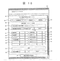
上記機器設備103の保守支援方法において、機器設備103に付帯した表示装置に表示される機器設備103の情報の例を、図10及び図11に示す。図10は、WWWブラウザ301を用いたシステムの表示例である。最適予防保全支援システムは、WWWブラウザ301で動作する。このブラウザ301上で、最適予防保全支援システム302の画面が表示される。画面上部には対象機器設備103の名称303が表示されており、保守支援の対象となっている機器設備103の名称が表示される。機器設備103を変更したいときには、対象機器設備変更入力ボタン304を用いる。対象機器設備103の詳細を知りたいとき、例えば運転経歴やメンテナンス情報等を知りたいときには、詳細情報表示ボタン305を用いて情報を呼び出す。
【0061】
損失関数とパラメータ定義画面部306の上部には、現在設定されている損失関数の表示部307があり、診断者が損失関数を新規作成するときは、損失関数新規作成ボタン308を用いて新規作成する。予め作成した他の損失関数を用いるときは、損失関数の変更ボタン309を用いて変更する。損失関数の定義を問い合わせるときはヘルプ表示ボタン310を用いる。
【0062】
損失関数とパラメータ定義画面306の中央部付近には、予防保全パラメータの入力部および表示部がある。この入力部及び表示部は、例えば、機能限界値入力部及び表示部311、保全限界値入力部及び表示部312、タイムラグ値入力部および表示部313、平均故障間隔値入力部および表示部314、故障時の損失値入力部および表示部315、定検コスト値入力部および表示部316、現行点検間隔値入力部および表示部317、保全コスト値入力部および表示部318、保全コスト値入力部および表示部319を有している。予防保全パラメータを新たに加えるときは、ユーザ定義パラメータ入力および表示部320を用いる。
【0063】
これらの予防保全パラメータは、図1に示した機器設備103、メンテナンス会社107、プラント・機器設備所有者106、インターネット109、情報提供会社108等から各種情報が送信されたら自動入力されるようにしてもよく、また診断者が収集した情報に基づいて手動で入力してもよい。機器設備103の損失を算出するときに、最新の値に更新するときは計算更新ボタン321を用いる。
【0064】
各情報が入力されると、最適点検間隔表示部322に最適点検間隔情報が表示される。診断者が表示された最適点検間隔情報に疑問を抱いたときには、ヘルプ表示ボタン323を用いてオンラインマニュアルを呼び出すことができる。損失の値だけを知るのではなく、損失の変化傾向を知るために、最適予防保全支援情報画面は変化傾向のグラフを表示できる。最適予防保全支援情報画面へは、最適予防保全支援情報移動ボタン324を押せば移動できる。
【0065】
図11は、最適予防保全支援情報画面の一例である。この画面の上部には損失関数およびパラメータ定義画面に移動するための移動ボタン325が設けられている。最適予防保全支援情報画面326は、損失関数およびパラメータ定義画面306同様にWWWブラウザ上に表示される。最適予防保全支援情報画面326に、機器設備103の予防保全に係る損失の時系列グラフ327や機器設備の最適予防保全時期に係る時系列グラフ328が表示可能である。予防保全に係る損失の時系列グラフ327では、横軸に機器設備103の運転時間が表示され、縦軸に予防保全に係る損失が表示される。このグラフにおいては、機器設備103の運転中に図11中に星印で示した最新の損失が算出され表示される。
【0066】
機器設備103の最適予防保全時期に係る時系列グラフ328では、横軸に機器設備103の運転時間が表示され、縦軸に最適点検推奨時期が表示される。このグラフでは、機器設備103の運転中に、図11中に星印で示した最適点検推奨時期の算出結果が表示される。このグラフで値がほとんど変化しなければ、機器設備103の運転開始前に予測した点検時期が最適であることが分かる。これに対して、グラフ中の値が変化するときは、それらの変化の様子を参考にして、予防保全の時期を決定する。最適予防保全支援情報画面326の下部には、トップページへの移動ボタン329やヘルプ表示ボタン330が配置されている。
【0067】
本実施例によれば、これまで当初立案した計画に従って実施されていた機器設備の予防保全を、予防保全のための点検期日までの間に得られる機器設備供用中に生じた種々の環境変化情報やそれに伴う機器の損失変化情報に基づいて、日程を変更可能にしたので、予防保全の信頼性が向上する。また、機器設備の遠隔監視情報と損失関数を用いているので、供用中の機器の予防保全に係る損失を時々刻々算出することが可能となる。算出された損失は、機器設備の予防保全の担当者が予防保全計画を策定する際の判断情報の1つとして利用できるる。無駄な予防保全を行う必要がなくなり、環境負荷を低減可能となるとともに予防保全に係るコストを削減できる。
【0068】
【発明の効果】
以上述べたように本発明によれば、機器設備の遠隔監視情報と損失関数を用いることにより、供用中の機器設備状態を時々刻々算出することが可能となり、予防保全を合理化できる。また、予防保全の信頼性を向上できる。
【図面の簡単な説明】
【図1】本発明に係る保守支援方法の一実施例の流れ図である。
【図2】本発明に係る保守支援方法で使用するプロセス情報と運転情報とメンテナンス情報の一例を示す図である。
【図3】本発明に係る保守支援方法で用いる予防保全パラメータの一例を示す図である。
【図4】本発明に係る保守支援方法を適用する設備構成の一実施例の模式図である。
【図5】損傷診断の一例を示すフローチャートである。
【図6】最適点検間隔を説明するための図である。
【図7】保守予定を説明するための図である。
【図8】機器設備の損傷を算出する例のフローチャートである。
【図9】温度分布と応力分布を説明する図である。
【図10】本発明に係る保守支援方法の一実施例で示される画面表示例である。
【図11】本発明に係る保守支援方法の一実施例で示される画面表示例である。
【符号の説明】
1…ガスタービン発電設備、2…圧縮機、3…燃焼器、4…タービン、5…ガスタービン駆動発電機、6…排熱回収ボイラ、7…蒸気タービン、8…蒸気タービン駆動発電機、9…復水器、10a〜10h…センサ、11…運転監視装置、12…運転監視装置側通信装置、13…通信回線、14…機器管理装置側通信装置、15…機器管理装置、16…解析サーバ、17…損傷に関するデータベース、18…損傷に関する知識ベース、19…WWWサーバ、20、21…wwwブラウザ、22…LAN、23…発電プラント、101…保守支援装置、103…プラント・機器設備(機器設備)、106…プラント・機器設備(機器設備)保有者、107…メンテナンス会社、108…情報提供会社、301…wwwブラウザ、302…最適予防保全支援システム画面表示、305…詳細情報表示ボタン、306…損失関数とパラメータ定義画面。[0001]
TECHNICAL FIELD OF THE INVENTION
The present invention relates to a maintenance support method for equipment, and more particularly to a maintenance support method suitable for power generation equipment.
[0002]
[Prior art]
Non-Patent
[0003]
Another example of a conventional maintenance method for equipment is described in Non-Patent
[0004]
A method of supporting operation control of a plant using a loss function is described in
[Patent Document 1]
JP-A-8-101710
[Non-patent document 1]
Ichiro Maeda “Results of combined cycle operation and improvement of reliability Kyushu Electric Power New Oita Power Station”, Journal of Gas Turbine Society of Japan, Vol. 24, no. 93, (1996), pp. 23-26
[Non-patent document 2]
Genichi Taguchi, "Quality Engineering Course (2): Quality Engineering at the Manufacturing Stage", Japan Standards Association, (1989) (especially pages 194 to 214)
[0005]
[Problems to be solved by the invention]
In the equipment maintenance method using the equivalent operation time described in
[0006]
In the maintenance method described in
[0007]
The present invention has been made in view of the above-mentioned disadvantages of the related art, and has as its object to rationalize preventive maintenance of plants and equipment. Another object of the present invention is to improve the reliability of preventive maintenance.
[0008]
[Means for Solving the Problems]
A feature of the present invention for achieving the above object is a support method for supporting maintenance of equipment using a loss function defined for each equipment, which changes with time obtained by remotely monitoring the equipment. Calculates a loss function that changes with time based on the information of the equipment to be operated, calculates at least one of the optimum inspection interval and the optimum maintenance limit based on the calculated loss function, and calculates the calculated optimum inspection interval or optimum maintenance limit. The maintenance scheduled time of the equipment is updated based on the above.
[0009]
In this feature, the loss function may have a plurality of preventive maintenance parameters that change with time, information on the equipment obtained by remote monitoring, and information on the equipment owner, the equipment maintenance operator, and the Internet. It is preferable to calculate a time-varying loss function using at least one of the information and the equipment information provided by at least one of the information providers.
[0010]
Also preferably, the scheduled maintenance time set before the operation of the equipment is updated by the loss function obtained at a time before the scheduled maintenance, and the maintenance time is set before the scheduled maintenance time set before the operation of the equipment. At the point of time, the function prediction value of the component provided in the equipment is obtained, and when the obtained function prediction value is different from the function limit change value set before the operation of the equipment, the prediction formula of the function limit is updated. Is also good. Further, the loss function may be obtained every hour at intervals, and the scheduled maintenance time of the equipment may be updated based on the loss function obtained every moment.
[0011]
Another feature of the present invention that achieves the above object is a support method for supporting maintenance of equipment using a loss function defined for each equipment, wherein the loss function is obtained by remotely monitoring the equipment. It has a plurality of parameters including information, determines a parameter value from the remote monitoring information, calculates a loss function, and calculates at least one of an optimum inspection interval and an optimum maintenance limit based on the calculated loss function. The scheduled maintenance time of the equipment is updated based on the optimum inspection interval or the optimum maintenance limit obtained.
[0012]
And in this feature, several parameters are the loss in case of equipment failure, average failure interval, current inspection interval, functional limit, current maintenance limit, and maintenance cost when exceeding the maintenance limit. It is preferable that the value of the parameter included in the loss function is determined by the inverse problem analysis method or the load-corresponding equivalent operation time method.
[0013]
Further, in the above feature, when the method of determining the parameter value is an inverse problem analysis method, the operation state of the equipment is estimated based on information obtained by remote monitoring, and the equipment is estimated based on the estimated information of the operation state. It is preferable to estimate the damage to the equipment by referring to the response surface relating to the damage to the components provided.When the method for determining the parameter value is the load-based equivalent operation time method, based on information obtained by remote monitoring of the equipment, It is preferable to estimate the damage to the equipment by referring to the load-corresponding equivalent operation time calculated for each deterioration / damage mode of the equipment.
[0014]
Further, the above-described features are suitable for the case where the equipment is a combined cycle including a gas turbine.
[0015]
BEST MODE FOR CARRYING OUT THE INVENTION
Hereinafter, an embodiment of a maintenance support system for equipment according to the present invention will be described with reference to the drawings. FIG. 1 is a schematic diagram of the basic concept of the present invention, showing equipment and a flow of information. This maintenance support system is an example in which the present invention is applied to a combined cycle. The
[0016]
A worker who plans to maintain the
[0017]
The
[0018]
The process information includes physical quantities such as 30 pieces of temperature information and displacement information marked with a1 to a30. The driving information includes information such as the driving time marked by b1 to b8. The maintenance information includes damage information, repair information, and the like marked with c1 to c15. In calculating the loss, all or a part of the process information, the operation information, and the maintenance information shown in FIG. 2 is used. The process information is obtained mainly from the
[0019]
The worker of the preventive maintenance receives, from the
[0020]
FIG. 4 shows a block diagram of a gas turbine combined power generation facility. The gas turbine
[0021]
Main equipment such as the
[0022]
The operation monitoring device 11 transmits the process information detected by the sensor 10i (i = a to h,...) And the operation information received from the gas turbine
[0023]
The
[0024]
The sensors 10i (i = a to h,...) Provide temperature information of the exhaust gas temperature a1, the discharge air temperature a3, and the inlet air temperature a7, the discharge air pressure a4, and the inlet air pressure a8 in the process information shown in FIG. , And information such as vibration information of the bearing vibration a12 and the shaft vibration a13. These measured process information or state quantities are sent to the operation monitoring device 11.
[0025]
Next, a method for calculating the loss of the
[0026]
L (t) = f (A (t), B (t), C (t), CL (t), D (t), DL (t), l (t), n (t), ui (t ),…)… (Equation 1)
Here, the parameters considered in the loss function are
A (t): Loss in case of equipment failure (yen)
B (t): Cost of periodic inspection (yen)
C (t): Maintenance (replacement) cost (yen)
CL (t): Maintenance cost when the maintenance limit is exceeded (yen)
D (t): Current maintenance limit (%, crack length, etc.)
DL (t): Functional limit (%, crack length, etc.)
l (t): Time lag (hour / year / day)
n (t): Current inspection interval (hour / year / day)
ui (t): mean time between failures (hour / year / day)
And the parameters to optimize are
n0(T): Optimum inspection interval (hour / year / day)
DU (t): optimum maintenance limit (%, crack length, etc.).
[0027]
L (t) on the left side of (Equation 1) is an expected value of a loss function occurring in the equipment. The parameter to be optimized is the optimal inspection interval n0(T) and / or the optimal maintenance limit DU (t). A (t), B (t), C (t), CL (t), D (t), DL (t), l (t), n (t), ui (t), n0(T) and DU (t) correspond to d1 to d11 in FIG. 3, respectively.
[0028]
The loss function L (t) is calculated as follows: loss A (t) in case of failure, cost B (t) for periodic inspection, cost C (t) for maintenance or replacement, and maintenance cost CL (t) when the maintenance limit is exceeded. ), Proportional to the square of the time lag l (t) and the current maintenance limit D (t), and inversely proportional to the square of the functional limit DL (t), the current service interval n (t) and the mean time between failures ui (t). decide. An example of the loss function L (t) is given by (Equation 2), and the optimum inspection interval n0An example of (t) is shown in (Equation 3), and an example of the optimal maintenance limit DU (t) is shown in (Equation 4).
[0029]
(Equation 1)
In (Equation 3), the optimum inspection interval n0(T) is the mean time between failures uiIt is proportional to the square root of the value obtained by dividing the cost B (t) of the periodic inspection by the loss A (t) at the time of failure. The optimum maintenance limit DU (t) is proportional to the fourth root of the value obtained by dividing the maintenance cost CL (t) by the cost A (t) at the time of failure and the functional limit DL (t). Conventionally, the optimum time interval and the optimum maintenance limit are predetermined values, but in the present embodiment, these are calculated every moment as a function of time. This allows for fast and most current optimization.
[0031]
Among the preventive maintenance parameters, loss A (t) in case of failure, cost B (t) for periodic inspection, cost C (t) required for maintenance or replacement, maintenance cost CL (t) when exceeding the maintenance limit. Is related to the maintenance cost of the
[0032]
The time lag l (t), the current service interval n (t), and the mean time between failures ui (t) are related to the time required for service. These times are calculated using at least one of the information provided from the
[0033]
FIG. 5 is a flowchart for calculating the loss function by grasping the functional limit of the
[0034]
From the estimated current value of the
[0035]
A loss related to preventive maintenance is calculated using collected data other than the damage diagnosis of the
[0036]
A method of calculating the optimum inspection interval of the
[0037]
At the beginning of the operation of the
[0038]
If the scheduled maintenance time t1 calculated before the operation of the
[0039]
Among the preventive maintenance parameters used when calculating the loss of the
[0040]
The relationship between the functional limit and the scheduled maintenance time will be described with reference to FIG. The horizontal axis in FIG. 7 indicates the operation time of the
[0041]
A method of calculating damage to the
[0042]
In step s3, signals from various sensors attached to the gas turbine are obtained. From the acquired sensor signals, in step s4, the temperature, the stress, and the strain of each high-temperature component are calculated using the relational expression between the sensor signal and the temperature, the stress, and the strain of the high-temperature component created in advance. Using the calculated temperature, stress, and strain, the change in the damage rate of the material is determined at step s5.
[0043]
In step s6, operation information of the gas turbine is obtained. Using the operation information and the change in the damage rate obtained in step s5, the creep damage and the thermal fatigue damage of the material are calculated in step s7. In step s8, an equivalent operation time is calculated from the calculated creep damage and thermal fatigue damage. Here, the equivalent operation time is equivalent to the damage caused by the load fluctuation such as the number of times of starting and stopping, the number of load fluctuations, and the number of stoppages due to the occurrence of an abnormality, and the damage caused by the gas turbine actually operated at a constant load. Is the time spent operating the gas turbine with constant load operation.
[0044]
The calculated equivalent operation time and damage data are provided to the gas turbine operator (step s9). The gas turbine operator creates operation plan information based on the damage information (step s10). The remaining life is calculated from the operation plan information provided by the gas turbine operator and the equivalent operation time calculated in step s8 (step s11). Then, information on the calculated remaining life is provided to the operator of the gas turbine (step s12). It is not always necessary to provide the damage information and remaining life information in step s9 and step s12 to the gas turbine operator.
[0045]
A method for obtaining a relational expression between the sensor signal of the gas turbine and the temperature, stress, and strain used in step s4 will be described using (Equation 5) and (Equation 6). The state of a gas turbine hot component depends on the temperature of the surrounding gas surrounding the component and the temperature of the gas cooling the hot component. Therefore, the relationship between the signal of the sensor installed in the gas turbine, the ambient gas temperature, and the cooling gas temperature is created in advance.
[0046]
The temperatures Ta and Tb detected by the sensors installed in the gas turbine are converted into the peripheral gas temperature Tg and the cooling gas temperature Tc of the gas turbine high-temperature component using (Equation 5). By the way, the damage of the gas turbine hot parts depends on the temperature, stress and strain generated in the hot parts, and these temperatures, stress and strain depend on the surrounding gas temperature and the cooling gas temperature of the hot parts. Therefore, the temperature Tm, the stress Sm, and the strain em of the gas turbine high-temperature component can be represented by the surrounding gas temperature Tg and the cooling gas temperature Tc. Then, using the peripheral gas temperature Tg and the cooling gas temperature Tc obtained by (Equation 5), the temperature Tm, stress Sm, and strain em of the hot turbine component are obtained as shown by (Equation 6).
[0047]
Tg = C0Ta + C1... (Equation 5)
Tc = C2Tb + C3
Here, each variable and coefficient in (Equation 5) represent the following contents.
Tg: ambient gas temperature (° C)
Tc: Cooling gas temperature (° C)
Ta: sensor a temperature (° C)
Tb: sensor b temperature (° C)
Ci (i = 1 to 4): Coefficient of relational expression between sensor and thermal boundary condition.
[0048]
Tm = r0+ R1Tb + r2Tb2+ R3Tc + r4Tc2+ R5TbTc {(° C.)} (Equation 6)
sm = r6+ R7Tb + r8Tb2+ R9Tc + r10Tc2+ R11TbTc (MPa)
em = r12+ RThirteenTb + r14Tb2+ RFifteenTc + r16Tc2+ R17TbTc
Here, each variable and coefficient in (Equation 6) represent the following contents.
Tm: target component temperature (° C)
sm: target component stress (MPa)
em: target component strain
ri(I = 1 to 17): Coefficient of thermal boundary condition and temperature-stress-strain relational expression
Tb: ambient gas temperature (° C)
Tc: Cooling gas temperature (° C).
[0049]
The relationship of (Equation 6) can be derived by various methods. FIG. 9 shows an example in which the relationship of (Equation 6) is obtained by numerical analysis. FIG. 9 shows the results of analysis (FEM) of the temperature distribution and stress distribution of the gas turbine rotor blade using the finite element method, in shades. The places where the concentration is low are places where the temperature and stress are high, and the places where the concentration is low are places where the temperature and stress are low. The numbers shown in the legends in the figure indicate the magnification with respect to the reference value. Since the temperature distribution and the stress distribution of the gas turbine blade depend on the load state and the operating state such as sudden start and stop, the finite element analysis is executed in advance by simulating various operating states as much as possible.
[0050]
Next, a response surface relating to the operating state of temperature and pressure is created using the operating state as a parameter. At this time, it is not possible to continuously simulate all the operating conditions. Therefore, the operating conditions are discretely selected, and the selected operating points are interpolated to create a response surface. The response surface is a function that associates multivariable parameters with each other. An example of this response surface is (Equation 6). Using (Equation 5) and (Equation 6), the signal obtained from the sensor is related to temperature and stress. The strain related to the fatigue life is also analyzed using the finite element method, and a response surface is created similarly. Thereby, the sensor signal is related to temperature, stress, and strain.
[0051]
A method of calculating component damage from temperature, stress, and strain will be described using a method using equivalent operation time as an example. The major damages to hot components of gas turbines are creep damage and thermal fatigue damage. Equivalent operating time D for creep damagecEOLIs obtained from (Equation 7). The creep damage rate depends on the temperature of the part during operation. Therefore, the temperature of the component is remotely monitored, and the damage ratio under the current operating condition with respect to the case where the device is operated under the design condition is obtained using (Equation 5).
[0052]
(Equation 2)
Here, each variable in (Equation 7) represents the following contents.
DcEOL: Equivalent operating time (hr) for creep damage
Hi: Actual operation time (hr)
Dc: creep damage rate at current temperature
Dc0: Creep damage rate at design basis
Tim: target component temperature during operation (° C)
i: Number of operation.
[0054]
Thermal fatigue damage can be calculated similarly to creep damage. Equivalent operating time D for thermal fatigue damagefEOLIs calculated using (Equation 8). Thermal fatigue damage depends on the temperature difference that occurs in the part during operation. When (Equation 8) is used, the damage rate is calculated for each operation mode (start / stop, load fluctuation, trip) of the gas turbine.
[0055]
(Equation 3)
Here, each variable in (Equation 8) represents the following contents.
DfEOL: Equivalent operating time (hr) for thermal fatigue damage
A: Conversion factor from the number of times of start / stop to equivalent operation time
j: Start / stop count
Df: Thermal fatigue damage rate at current temperature
Df0: Thermal fatigue damage rate at the time of design standard
B: Coefficient for converting the number of load changes into equivalent operation time
C: Coefficient for converting the number of trips to equivalent operation time
l: Number of trips
Tnm: temperature (° C).
[0057]
After calculating the equivalent operation time for creep damage and thermal fatigue damage, the equivalent operation time L is calculated as shown in (
[0058]
LOL= DcEOL+ DfEOL… (Equation 9)
LOL: Online equivalent operation time (hr).
[0059]
When calculating the damage to the
[0060]
FIGS. 10 and 11 show examples of information on the
[0061]
Above the loss function and parameter
[0062]
Near the center of the loss function and
[0063]
These preventive maintenance parameters are automatically inputted when various information is transmitted from the
[0064]
When each information is input, the optimal inspection interval information is displayed on the optimal inspection
[0065]
FIG. 11 is an example of the optimal preventive maintenance support information screen. A
[0066]
In the time-
[0067]
According to this embodiment, preventive maintenance of equipment and equipment that has been carried out in accordance with the plan originally planned up to now can be performed by various kinds of environmental change information generated during the equipment and equipment operation obtained until the inspection date for preventive maintenance. The schedule can be changed on the basis of the information on the change in the loss of the equipment associated therewith, thereby improving the reliability of the preventive maintenance. Further, since the remote monitoring information of the equipment and the loss function are used, it is possible to calculate the loss related to the preventive maintenance of the equipment in operation every moment. The calculated loss can be used as one piece of judgment information when a person in charge of preventive maintenance of equipment and facilities formulates a preventive maintenance plan. It is not necessary to perform useless preventive maintenance, and it is possible to reduce the environmental load and to reduce the cost for preventive maintenance.
[0068]
【The invention's effect】
As described above, according to the present invention, by using the remote monitoring information and the loss function of the equipment, it is possible to calculate the state of the equipment in use every moment, and the preventive maintenance can be rationalized. In addition, the reliability of preventive maintenance can be improved.
[Brief description of the drawings]
FIG. 1 is a flowchart of an embodiment of a maintenance support method according to the present invention.
FIG. 2 is a diagram showing an example of process information, operation information, and maintenance information used in the maintenance support method according to the present invention.
FIG. 3 is a diagram showing an example of a preventive maintenance parameter used in the maintenance support method according to the present invention.
FIG. 4 is a schematic diagram of an embodiment of a facility configuration to which a maintenance support method according to the present invention is applied.
FIG. 5 is a flowchart illustrating an example of a damage diagnosis.
FIG. 6 is a diagram for explaining an optimum inspection interval.
FIG. 7 is a diagram for explaining a maintenance schedule.
FIG. 8 is a flowchart illustrating an example of calculating damage to equipment.
FIG. 9 is a diagram illustrating a temperature distribution and a stress distribution.
FIG. 10 is a screen display example shown in one embodiment of the maintenance support method according to the present invention.
FIG. 11 is a screen display example shown in an embodiment of the maintenance support method according to the present invention.
[Explanation of symbols]
DESCRIPTION OF
Claims (11)
Priority Applications (1)
| Application Number | Priority Date | Filing Date | Title |
|---|---|---|---|
| JP2002307780A JP2004145496A (en) | 2002-10-23 | 2002-10-23 | Maintenance supporting method for equipment and facility |
Applications Claiming Priority (1)
| Application Number | Priority Date | Filing Date | Title |
|---|---|---|---|
| JP2002307780A JP2004145496A (en) | 2002-10-23 | 2002-10-23 | Maintenance supporting method for equipment and facility |
Publications (1)
| Publication Number | Publication Date |
|---|---|
| JP2004145496A true JP2004145496A (en) | 2004-05-20 |
Family
ID=32454098
Family Applications (1)
| Application Number | Title | Priority Date | Filing Date |
|---|---|---|---|
| JP2002307780A Pending JP2004145496A (en) | 2002-10-23 | 2002-10-23 | Maintenance supporting method for equipment and facility |
Country Status (1)
| Country | Link |
|---|---|
| JP (1) | JP2004145496A (en) |
Cited By (19)
| Publication number | Priority date | Publication date | Assignee | Title |
|---|---|---|---|---|
| JP2008216042A (en) * | 2007-03-05 | 2008-09-18 | Omron Corp | Calibration support device, calibration support method, program, and record medium |
| US7472024B2 (en) | 2006-12-27 | 2008-12-30 | Kabushiki Kaisha Toshiba | Data analysis apparatus and method |
| JP2009003758A (en) * | 2007-06-22 | 2009-01-08 | Toshiba Corp | Device for supporting calibration of measuring instrument for plant and method for supporting calibration of measuring instrument for plant |
| JP2011106467A (en) * | 2011-02-28 | 2011-06-02 | Hitachi Ltd | Method for displaying display screen in system for diagnosing performance of gas turbine |
| JP2012194186A (en) * | 2012-06-12 | 2012-10-11 | Omron Corp | Calibration support device, calibration support method, program, and recording medium |
| WO2014010632A1 (en) * | 2012-07-13 | 2014-01-16 | 日立建機株式会社 | Maintenance management device for operating machinery |
| WO2014136532A1 (en) * | 2013-03-04 | 2014-09-12 | 三菱重工業株式会社 | Operation plan creation device, operation plan creation method, and operation plan creation program |
| JP2014219670A (en) * | 2013-04-15 | 2014-11-20 | ゼネラル・エレクトリック・カンパニイ | Component identification system |
| JP2015525354A (en) * | 2012-06-19 | 2015-09-03 | ゲーコーエヌ エアロスペース スウェーデン アーベー | Reliable prediction of machine part life consumption |
| JP2015529794A (en) * | 2012-06-19 | 2015-10-08 | ゲーコーエヌ エアロスペース スウェーデン アーベー | Simple calculation model generation method and component consumption life prediction method |
| JP2018036679A (en) * | 2016-08-29 | 2018-03-08 | 川崎重工業株式会社 | Plan creation device and plan creation method related to employment of energy demand facility |
| JP2019003440A (en) * | 2017-06-15 | 2019-01-10 | 株式会社日立製作所 | Maintenance management system, abnormality detection device, and maintenance plan creation device |
| CN109784510A (en) * | 2019-01-21 | 2019-05-21 | 上海船舶研究设计院(中国船舶工业集团公司第六0四研究院) | Ship equipment health maintenance method and system |
| JP2021157639A (en) * | 2020-03-27 | 2021-10-07 | 株式会社Sumco | Maintenance managing device, maintenance managing method and maintenance managing program |
| JP7154469B1 (en) * | 2022-03-09 | 2022-10-17 | 三菱電機株式会社 | Maintenance plan support system, maintenance plan support method, and maintenance plan support program |
| US11550874B2 (en) * | 2014-04-11 | 2023-01-10 | Hartford Steam Boiler Inspection And Insurance Company | Future reliability prediction based on system operational and performance data modelling |
| US11615348B2 (en) | 2019-09-18 | 2023-03-28 | Hartford Steam Boiler Inspection And Insurance Company | Computer-based systems, computing components and computing objects configured to implement dynamic outlier bias reduction in machine learning models |
| US11636292B2 (en) | 2018-09-28 | 2023-04-25 | Hartford Steam Boiler Inspection And Insurance Company | Dynamic outlier bias reduction system and method |
| US11868425B2 (en) | 2011-08-19 | 2024-01-09 | Hartford Steam Boiler Inspection And Insurance Company | Dynamic outlier bias reduction system and method |
Citations (3)
| Publication number | Priority date | Publication date | Assignee | Title |
|---|---|---|---|---|
| JP2002195056A (en) * | 2000-12-22 | 2002-07-10 | Central Res Inst Of Electric Power Ind | Disposal loss minimization method and system of gas turbine high-temperature component and computer- readable recording medium with gas turbine maintenance optimization supporting program recorded thereon |
| JP2002297710A (en) * | 2001-03-29 | 2002-10-11 | Hitachi Ltd | System and method for supporting maintenance plan of power plant |
| JP2003005822A (en) * | 2001-06-25 | 2003-01-08 | Mitsubishi Chemicals Corp | System for managing equipment |
-
2002
- 2002-10-23 JP JP2002307780A patent/JP2004145496A/en active Pending
Patent Citations (3)
| Publication number | Priority date | Publication date | Assignee | Title |
|---|---|---|---|---|
| JP2002195056A (en) * | 2000-12-22 | 2002-07-10 | Central Res Inst Of Electric Power Ind | Disposal loss minimization method and system of gas turbine high-temperature component and computer- readable recording medium with gas turbine maintenance optimization supporting program recorded thereon |
| JP2002297710A (en) * | 2001-03-29 | 2002-10-11 | Hitachi Ltd | System and method for supporting maintenance plan of power plant |
| JP2003005822A (en) * | 2001-06-25 | 2003-01-08 | Mitsubishi Chemicals Corp | System for managing equipment |
Cited By (27)
| Publication number | Priority date | Publication date | Assignee | Title |
|---|---|---|---|---|
| US7472024B2 (en) | 2006-12-27 | 2008-12-30 | Kabushiki Kaisha Toshiba | Data analysis apparatus and method |
| JP2008216042A (en) * | 2007-03-05 | 2008-09-18 | Omron Corp | Calibration support device, calibration support method, program, and record medium |
| JP2009003758A (en) * | 2007-06-22 | 2009-01-08 | Toshiba Corp | Device for supporting calibration of measuring instrument for plant and method for supporting calibration of measuring instrument for plant |
| JP2011106467A (en) * | 2011-02-28 | 2011-06-02 | Hitachi Ltd | Method for displaying display screen in system for diagnosing performance of gas turbine |
| US11868425B2 (en) | 2011-08-19 | 2024-01-09 | Hartford Steam Boiler Inspection And Insurance Company | Dynamic outlier bias reduction system and method |
| JP2012194186A (en) * | 2012-06-12 | 2012-10-11 | Omron Corp | Calibration support device, calibration support method, program, and recording medium |
| JP2015529794A (en) * | 2012-06-19 | 2015-10-08 | ゲーコーエヌ エアロスペース スウェーデン アーベー | Simple calculation model generation method and component consumption life prediction method |
| JP2015525354A (en) * | 2012-06-19 | 2015-09-03 | ゲーコーエヌ エアロスペース スウェーデン アーベー | Reliable prediction of machine part life consumption |
| WO2014010632A1 (en) * | 2012-07-13 | 2014-01-16 | 日立建機株式会社 | Maintenance management device for operating machinery |
| JP2014021627A (en) * | 2012-07-13 | 2014-02-03 | Hitachi Constr Mach Co Ltd | Maintenance management device for operating machine |
| US10235658B2 (en) | 2012-07-13 | 2019-03-19 | Hitachi Construction Machinery Co., Ltd. | Maintenance management device for operating machinery |
| GB2526218A (en) * | 2013-03-04 | 2015-11-18 | Mitsubishi Heavy Ind Ltd | Operation plan creation device, operation plan creation method, and operation plan creation program |
| GB2526218B (en) * | 2013-03-04 | 2020-10-14 | Mitsubishi Heavy Ind Ltd | Operation plan creation device, operation plan creation method, and operation plan creation program |
| WO2014136532A1 (en) * | 2013-03-04 | 2014-09-12 | 三菱重工業株式会社 | Operation plan creation device, operation plan creation method, and operation plan creation program |
| US10466672B2 (en) | 2013-03-04 | 2019-11-05 | Mitsubishi Heavy Industries, Ltd. | Operation plan creation device, operation plan creation method, and operation plan creation program |
| JP2014170376A (en) * | 2013-03-04 | 2014-09-18 | Mitsubishi Heavy Ind Ltd | Operation plan preparation apparatus, operation plan preparation method, and operation plan preparation program |
| JP2014219670A (en) * | 2013-04-15 | 2014-11-20 | ゼネラル・エレクトリック・カンパニイ | Component identification system |
| US11550874B2 (en) * | 2014-04-11 | 2023-01-10 | Hartford Steam Boiler Inspection And Insurance Company | Future reliability prediction based on system operational and performance data modelling |
| JP2018036679A (en) * | 2016-08-29 | 2018-03-08 | 川崎重工業株式会社 | Plan creation device and plan creation method related to employment of energy demand facility |
| JP2019003440A (en) * | 2017-06-15 | 2019-01-10 | 株式会社日立製作所 | Maintenance management system, abnormality detection device, and maintenance plan creation device |
| US11636292B2 (en) | 2018-09-28 | 2023-04-25 | Hartford Steam Boiler Inspection And Insurance Company | Dynamic outlier bias reduction system and method |
| US11803612B2 (en) | 2018-09-28 | 2023-10-31 | Hartford Steam Boiler Inspection And Insurance Company | Systems and methods of dynamic outlier bias reduction in facility operating data |
| CN109784510A (en) * | 2019-01-21 | 2019-05-21 | 上海船舶研究设计院(中国船舶工业集团公司第六0四研究院) | Ship equipment health maintenance method and system |
| US11615348B2 (en) | 2019-09-18 | 2023-03-28 | Hartford Steam Boiler Inspection And Insurance Company | Computer-based systems, computing components and computing objects configured to implement dynamic outlier bias reduction in machine learning models |
| JP2021157639A (en) * | 2020-03-27 | 2021-10-07 | 株式会社Sumco | Maintenance managing device, maintenance managing method and maintenance managing program |
| JP7154469B1 (en) * | 2022-03-09 | 2022-10-17 | 三菱電機株式会社 | Maintenance plan support system, maintenance plan support method, and maintenance plan support program |
| WO2023170833A1 (en) * | 2022-03-09 | 2023-09-14 | 三菱電機株式会社 | Maintenance plan assistance system, maintenance plan assistance method, and maintenance plan assistance program |
Similar Documents
| Publication | Publication Date | Title |
|---|---|---|
| JP2004145496A (en) | Maintenance supporting method for equipment and facility | |
| US7065471B2 (en) | Method and system for diagnosing state of gas turbine | |
| US6343251B1 (en) | Method and system for monitoring the operation of and predicting part life consumption for turbomachinery | |
| JP4067811B2 (en) | Remote monitoring system and remote monitoring method for high temperature parts | |
| JP2004211587A (en) | Operational support system for power generation plant | |
| CN110431502B (en) | Precursor detection system and precursor detection method | |
| EP2241726A2 (en) | A method for the repair of an engine and corresponding systems for monitoring this engine | |
| KR20020001747A (en) | Service Life Management System for High-Temperature Part of Gas Turbine | |
| JP5973096B1 (en) | Plant analysis apparatus, plant analysis method, and program | |
| JP5938888B2 (en) | Server, equipment maintenance support system, method and program | |
| JP2003067038A (en) | Operation maintenance information providing system, and management cost collecting method | |
| US20130238256A1 (en) | Method and system to model risk of unplanned outages of power generation machine | |
| JP2011106467A (en) | Method for displaying display screen in system for diagnosing performance of gas turbine | |
| JP3742310B2 (en) | Power generation equipment maintenance support system | |
| JP2002330542A (en) | Supporting system for operation and maintenance program of generator equipment | |
| JP4069944B2 (en) | Power plant control method, operation command method | |
| WO2004021097A1 (en) | Plant apparatus operation support device | |
| JP2002108440A (en) | Damage diagnosing device for power generation facilities | |
| CN108463616B (en) | Device analysis apparatus, device analysis method, and non-transitory computer-readable medium | |
| US11566983B2 (en) | Apparatus state estimation device, apparatus state estimation method and program | |
| JP2021111207A (en) | Plant performance evaluation system and plant performance evaluation method | |
| RU2668852C1 (en) | Method and system of accounting residual operation life of turbo-aggregate components | |
| JP2005018299A (en) | Maintenance management system and maintenance management method for cooker and the like | |
| JP2001303909A (en) | Method and apparatus for controlling life cycle maintenance of steam turbine member | |
| EP4325314A2 (en) | Systems and methods for estimating future risk of failure of a wind turbine component using machine learning |
Legal Events
| Date | Code | Title | Description |
|---|---|---|---|
| A621 | Written request for application examination |
Free format text: JAPANESE INTERMEDIATE CODE: A621 Effective date: 20050131 |
|
| RD01 | Notification of change of attorney |
Free format text: JAPANESE INTERMEDIATE CODE: A7421 Effective date: 20060420 |
|
| A977 | Report on retrieval |
Free format text: JAPANESE INTERMEDIATE CODE: A971007 Effective date: 20071001 |
|
| A131 | Notification of reasons for refusal |
Free format text: JAPANESE INTERMEDIATE CODE: A131 Effective date: 20071120 |
|
| A521 | Request for written amendment filed |
Free format text: JAPANESE INTERMEDIATE CODE: A523 Effective date: 20080121 |
|
| A02 | Decision of refusal |
Free format text: JAPANESE INTERMEDIATE CODE: A02 Effective date: 20080603 |