JP2004136831A - Sound generating device and automobile - Google Patents
Sound generating device and automobile Download PDFInfo
- Publication number
- JP2004136831A JP2004136831A JP2002305199A JP2002305199A JP2004136831A JP 2004136831 A JP2004136831 A JP 2004136831A JP 2002305199 A JP2002305199 A JP 2002305199A JP 2002305199 A JP2002305199 A JP 2002305199A JP 2004136831 A JP2004136831 A JP 2004136831A
- Authority
- JP
- Japan
- Prior art keywords
- sound
- speed
- vehicle
- speaker
- running
- Prior art date
- Legal status (The legal status is an assumption and is not a legal conclusion. Google has not performed a legal analysis and makes no representation as to the accuracy of the status listed.)
- Pending
Links
- 230000005856 abnormality Effects 0.000 claims description 12
- 238000013459 approach Methods 0.000 abstract description 3
- 230000005236 sound signal Effects 0.000 description 16
- 238000010586 diagram Methods 0.000 description 11
- 238000000034 method Methods 0.000 description 9
- 239000003112 inhibitor Substances 0.000 description 8
- 238000012360 testing method Methods 0.000 description 7
- 239000000446 fuel Substances 0.000 description 5
- 230000008569 process Effects 0.000 description 5
- 238000012545 processing Methods 0.000 description 5
- 230000015654 memory Effects 0.000 description 4
- 230000007935 neutral effect Effects 0.000 description 4
- 230000006378 damage Effects 0.000 description 3
- 230000000994 depressogenic effect Effects 0.000 description 3
- 230000006870 function Effects 0.000 description 3
- 208000027418 Wounds and injury Diseases 0.000 description 2
- 230000002159 abnormal effect Effects 0.000 description 2
- 230000005540 biological transmission Effects 0.000 description 2
- 230000000694 effects Effects 0.000 description 2
- 230000007274 generation of a signal involved in cell-cell signaling Effects 0.000 description 2
- 208000014674 injury Diseases 0.000 description 2
- 230000004807 localization Effects 0.000 description 2
- 238000005259 measurement Methods 0.000 description 2
- 230000007246 mechanism Effects 0.000 description 2
- 230000001133 acceleration Effects 0.000 description 1
- 239000000853 adhesive Substances 0.000 description 1
- 230000001070 adhesive effect Effects 0.000 description 1
- 230000032683 aging Effects 0.000 description 1
- 230000008859 change Effects 0.000 description 1
- 230000000881 depressing effect Effects 0.000 description 1
- 238000001514 detection method Methods 0.000 description 1
- 230000007613 environmental effect Effects 0.000 description 1
- 239000002803 fossil fuel Substances 0.000 description 1
- 238000007689 inspection Methods 0.000 description 1
- 230000002265 prevention Effects 0.000 description 1
- 230000008439 repair process Effects 0.000 description 1
- 239000004065 semiconductor Substances 0.000 description 1
- 230000002194 synthesizing effect Effects 0.000 description 1
Images


Classifications
-
- B—PERFORMING OPERATIONS; TRANSPORTING
- B60—VEHICLES IN GENERAL
- B60Q—ARRANGEMENT OF SIGNALLING OR LIGHTING DEVICES, THE MOUNTING OR SUPPORTING THEREOF OR CIRCUITS THEREFOR, FOR VEHICLES IN GENERAL
- B60Q5/00—Arrangement or adaptation of acoustic signal devices
- B60Q5/005—Arrangement or adaptation of acoustic signal devices automatically actuated
- B60Q5/008—Arrangement or adaptation of acoustic signal devices automatically actuated for signaling silent vehicles, e.g. for warning that a hybrid or electric vehicle is approaching
Landscapes
- Physics & Mathematics (AREA)
- Acoustics & Sound (AREA)
- Engineering & Computer Science (AREA)
- Mechanical Engineering (AREA)
- Fittings On The Vehicle Exterior For Carrying Loads, And Devices For Holding Or Mounting Articles (AREA)
- Electric Propulsion And Braking For Vehicles (AREA)
Abstract
Description
【0001】
【発明の属する技術分野】
本発明は、自動車に関し、走行音などの音響を発生する装置や当該装置を具備する自動車等に関する。
【0002】
【従来の技術】
近年、排気ガスなどの環境問題に対する関心が高まり、自動車のハイブリッド化が進行しつつある。また、ガソリンや軽油などの化石燃料を使用せず、電気式モータや燃料電池など、排気ガスや騒音に対して対策が施された自動車が市販されるようになってきた。
【0003】
【発明が解決しようとする課題】
しかし、ハイブリッド車に特有の事故が増加している。その原因は、従来のエンジンに比べて音が静かな電気式モータを使用していることによる。従来、歩行者は、見通しのきかない路上では、自動車の発生するエンジンの騒音、排気音、タイヤの走行音などを聴いて車の接近に対する注意を払ってきた。しかし、ハイブリッド車では、エンジンの騒音、排気音がないか極めて小さく、歩行者が車の接近を察知しにくくなっている。また、高齢者はとくに音に対して年齢とともに検知しにくくなっていくことを考えると、今後の高齢化社会においては、ハイブリッド車による人身事故は増加してゆく可能性がある。また、電気自動車、燃料電池自動車などが普及してくると、さらに歩行者が車の接近を察知しにくくなり、今以上に人身事故は増加してゆく可能性がある。
【0004】
従って、ハイブリッド車、電気自動車、燃料電池自動車など、騒音が小さい自動車において、歩行者が車の接近を察知できるようにして、人身事故の防止ができるようにする必要がある。
【0005】
【課題を解決するための手段】
上記の課題を解決するために、本発明の自動車の音響発生装置は、以下のような手段を採用する。
(1)自動車が前進開始時、または前進中に、外部に音響を発生する音響発生装置。
(2)自動車の速度に基づいて、外部に音響を発生する音響発生装置。
(3)自動車の速度に応じて、異なった音響を発生する(1)、(2)の音響発生装置。
(4)高速の場合に、高い周波数成分を有する音響を発生する(1)、(2)の音響発生装置。
(5)複数のスピーカを備え、発生する音響の方向を、走行によって変更する音響発生装置。
(6)スピーカを備え、スピーカの方向を、走行によって変更する音響発生装置。
(7)前記音響の発生に関して異常を検出する手段を備え、意図的な破壊を防止する。
【0006】
【発明の実施の形態】
(実施の形態1)
図1は、本発明の自動車の音響発生装置のブロック図である。電気自動車10は、ハイブリッド車、電気自動車、燃料電池自動車のように電気モータを推進力に使用する自動車であり、自動車操縦走行部1、センサ2、音響信号発生部3、スピーカ4を備えている。
【0007】
自動車操縦走行部1は、エネルギー源である電力を貯える蓄電池、電気モータ、電気モータの動力を走行系へ伝える伝動機構、走行用の車輪、操縦用のハンドル、アクセル、ブレーキ、始動用のキー、自動車の状態を表示する表示パネルなど、周知の構成から成る。センサ2は、自動車の電気モータの駆動状態、走行方向、走行速度などを検知し、電圧、電流、パルス信号、デジタルデータなどの形式で出力する。音響信号発生部3は、センサ2の出力信号にしたがって、所定の音響信号を発生する。スピーカ4は、音響信号を音波に変換し、車外に音響を放射する。
【0008】
スピーカ4は複数でもよく、その場合は、図2のスピーカ4R、4Lに示すように、自動車の前方左右に取り付けられる。
【0009】
本発明の音響発生装置では、自動車が前進開始時、または前進中に、次のような機能を有する。すなわち、外部に音響を発生する、自動車の速度に基づいて外部に音響を発生する、自動車の速度に応じて異なった音響を発生する、高速の場合に、高速走行を感知し易い高い周波数成分を有する音響を発生する、などである。
【0010】
また、複数のスピーカを備え、走行によって、発生する音響の方向を変更したり、走行によってスピーカの方向を変更したりするような機能も持たせる。
【0011】
図3は、更に詳しい本発明の実施の形態のブロック図である。センサ2として、1つ又は複数の種々のセンサを使用する。キーセンサ21は、自動車のキーが挿入されたことを検知するセンサで、走行準備中であることを検知する。アクセルセンサ22は、アクセルが踏み込まれたときの踏み込みの度合いにしたがって変化する情報を出力する。電気自動車10では、アクセルの踏み込みに応じて電気モータへの電力を制御するようにしているので、このような制御信号をセンサの信号として用いることができる。シフトセンサ23は、シフトギアの状態を検出し、その状態を表す信号を出力するものである。オートマティック車では、運転者がシフトギアを操作せずとも、アクセルや自動車の速度、加速度にしたがってシフトギアを最適に切換制御するようになっている。電気自動車では、シフトギアを使用しない設計もあるが、ハイブリッド車では、搭載する場合も考えられる。シフトギアを装着しない場合は、シフトセンサ23は、先進、後進を検知するものとする。速度センサ24は、実際の速度に応じた情報を出力する。電気モータから車輪までの動力伝導機構に設けられる回転速度センサや車輪の回転速度センサなどもこのセンサの一種である。アクセルセンサ22やシフトセンサ23は、運転者の操縦意志を表すものであって、そのとき車の実際の速度を表すとは限らない。実際の車の速度の変化に対して、少し事前に速度を表すものといってもよい。方向指示センサ25は、方向指示ウインカを表示するための操作を検知する。ハンドルセンサ26は、自動車のハンドルの操作回転角や、車輪の左右方向のシフト状況を表す情報を出力する。方向指示センサ25は、これから方向転換することを早めに検知し、ハンドルセンサ26は、実際に方向転換しつつある状況を検出する。
【0012】
音響信号発生部3は、自動車が各種走行時に出す音響信号を発生する。エンジン自動車のエンジン始動音、走行開始音、低速走行音、中速走行音、高速走行音をデジタル録音したサンプルデータを、内部のメモリ32に記憶しておく。アドレス選択部31は、各種センサ21〜24の出力データを受取り、エンジン始動音、走行開始音、低速走行音、中速走行音、高速走行音の内から、どの音を発生させるかを判断、選択し、選択した音のアドレスをメモリ32に印加して、サンプルデータを読み出す。なお、エンジン停止状態では、音波は不要であるので、サンプルデータを読み出さないようにする。読み出されたサンプルデータは音量調節部33に印加される。音量調節部33は、方向指示センサ25、ハンドルセンサ26のデータにしたがってスピーカ4Lと4Rへの信号の配分バランスを調節し、アナログ信号に変換して、図示しないパワーアンプを経て、スピーカ4Lと4Rに出力する。
【0013】
車のキーを回したときは、キーセンサ21の出力データがONとなるが、アクセルセンサ22や速度センサ24の出力は、ゼロである。この状態では、アドレス選択部31は、エンジン始動音を選択する。方向指示センサ25の出力はゼロであるので、音量調節部33は、スピーカ4L,4Rに同じ音量の信号を出力する。つぎに、アクセルを踏み込んで車を前に進めると、キーセンサ21はONであり、アクセルセンサ22が低速のデータを出力し、シフトセンサ23は、前進信号を出力する。この状態では、エンジン始動音と低速走行音の両方のサンプルデータを選択する。
【0014】
更にアクセルを踏み込むと、アクセルセンサ22は、中速のデータを出力するので、アドレス選択部31は、中速走行音を選択する。更にアクセルを踏み込むと、アクセルセンサ22は、高速のデータを出力するので、アドレス選択部31は、高速走行音を選択する。車が実際に加速されると、速度センサ24も高速状態を示すデータを出力する。
【0015】
左折、右折する場合は、方向指示センサ25が、方向データを出力する。ハンドルセンサ26は、ハンドルの操作角度データを出力する。これらのデータが音量調節部33に印加され、スピーカ4L,4Rへの音量が調節される。旋回半径が小さいほど、旋回方向のスピーカの音量が大きくなる。
【0016】
以上のように、本発明の音響装置を電気自動車に搭載すると、エンジン自動車が、エンジン始動、発進、低速、中速、高速での走行時に発生する音と同様の音を、電気自動車が発生することになり、歩行者は、これまでと同様に、車の接近や走行状態を、慣れ親しんだ音により感知でき、車に注意を払い易くなる。
【0017】
なお、シフトセンサ23が後進を示すときには、従来からある後進を示す注意音や、注意喚起メッセージを出してもよい。
【0018】
(実施の形態2)
図4は、エンジンコンピュータを利用して車速によりスピーカ音を制御する回路の例である。エンジンECU(エレクロトニック・コントロール・ユニット)54に音響発生用の回路を付加して音響制御ブロック50を構成する。付加部分は、音響信号発生部3、パワーアンプ55、アンプ57、トランジスタ58、抵抗56、59、60よりなっている。イグニッションスイッチ51は、インヒビタスイッチ52の回転子に結合され、インヒビタスイッチ52のパーキングレンジPとニュートラルレンジNの接点は、抵抗53で終端され、端子T1に接続される。なお、インヒビタスイッチ52は、オートマティック車に使用され、シフトポイントの検出を行なうもので、Lは1速、2は2速、3は3速、Rはリバースであり、N、P以外では、エンジンの始動はできない。速度センサ24の出力パルス信号は、端子T2に印加される。端子T3より、電源電圧が、抵抗60を介してトランジスタ58のエミッタに印加される。端子T4は、抵抗59を介してトランジスタ58のベースに接続され、トランジスタ58を活性状態又はOFFにする。端子T7より、音源選択データが音響信号発生部3に供給され、車速に応じた音響信号が選択される。音響信号は、パワーアンプ55により増幅され、スピーカ4に供給されて音波になる。パワーアンプ55の出力端子、トランジスタ58のコレクタおよび抵抗56の一端は結合されている。抵抗56の他端は、接地されている。アンプ57は、抵抗56の両端の電圧を端子T5に伝える。端子T6は、パワーアンプ55の制御端子に結合され、パワーアンプ55を遮断することができる。エンジンECUは、周知のエンジン制御に加えて、本発明の車速による音響信号の制御を行なう。
【0019】
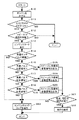
次に、図4の回路の動作を、図5に示すフローチャートに基づいて説明する。なお、以下(Sxx)は、図5のフローチャートにおける各ステップを表す。
【0020】
最初、車は停止しているものとする。音響信号発生部3には、端子T7から無音選択データが与えられており、音響信号を発生しない。ステップ(S10)において、エンジンを掛けるために、イグニッションスイッチ51をONとすると、インヒビタスイッチ52に電圧が印可され、パーキングP又はニュートラルNの時のみ、抵抗53に電圧が印可される。エンジンECU54は、端子T1を監視し、(S11)において、P、Nか、それ以外かを判定する。P、N以外であれば、故障であるので故障表示を行ない、エンジンスタートしない(S24)。
【0021】
(S11)においてYESであれば、(S12)において、スピーカの状態を検査する。このために、まず、端子T6より、パワーアンプ55の制御端子に、制御信号を加え、パワーアンプ55を遮断状態にする。遮断状態とは、パワーアンプ55の出力トランジスタがOFF状態をいう。パワーアンプ55の出力端子のインピーダンスは、無限大に近い高インピーダンスとなる。この状態から、端子T4の電圧を電源電圧(例えば5V)から、0Vに変えて、トランジスタ58をOFFから活性状態にする。抵抗56、60の抵抗値をほぼ同じ1kΩとする。スピーカ4のボイスコイルの直流抵抗は、通常10Ω以下である。スピーカ4が接続されている場合は、コレクタの電圧は、殆ど0Vに近い低い電圧となる。スピーカ4が、何らかの理由で取り外されていたり、スピーカケーブルが切断されていたりすると、ボイスコイルの直流抵抗がなくなり、コレクタの電圧は、約2.5Vに近い電圧となる。アンプ57は、コレクタ電圧(抵抗56の両端の電圧)を端子T5に伝える。エンジンECU54は、端子T5の電圧によりスピーカの抵抗の有無を判断する。スピーカの抵抗値を検出できなければ、(S12)において、NOであるので、エンジンをスタートさせずに終了する。
【0022】
(S12)においてYESであれば、スピーカ抵抗の検査モードを解除する。すなわち、端子T4を電源電圧に戻してトランジスタ58をOFFにし、端子T6からのパワーアンプ遮断の制御信号を解除する。そして、エンジンを始動し、走行に入る(S13)。この時、エンジン音を選択する音源選択データを端子T7より、音響信号発生部3に与え、パワーアンプ55を通じてエンジン音をスピーカより出す。
【0023】
次に、車速の計測に入る。(S14)において、速度センサ24から端子T2を通して取り込んだ車速パルスを、エンジンECU54において計数する。パルスが無ければ、NOとなる。エンジンスタートしシフトレバーが走行モード位置にあるのにパルスがないのは、異常とみなし、エンジンチェックランプを点灯し、エンドとなる(S23)。
【0024】
(S14)において、パルスが検知されれば、YESであるので、車速パルスが低速域かどうか判定する(S15)。YESであれば、端子T7より、低速域の音響信号の音源選択データを音響信号発生部3に供給し、低速域の音波をスピーカより放射させる(S16)。(S15)においてNOであれば、(S17)において、車速パルスが中速域かどうか判定する。YESであれば、端子T7より、中速域の音響信号の音源選択データを音響信号発生部3に供給し、中速域の音波をスピーカより放射させる(S18)。(S17)においてNOであれば、(S19)において、車速パルスが高速域かどうか判定する。(S19)においてYESであれば、端子T7より、高速域の音響信号の音源選択データを音響信号発生部3に供給し、高速域の音波をスピーカより放射させる。(S19)においてNOであれば、異常と判断され、(S23)の処理を行なう。
【0025】
(S16)、(S18)、(S20)において、各車速域に対応した音響信号を出力した状態において、ステップ(S21)で、抵抗56の両端の電圧が既定の範囲にあるかどうかを、アンプ57を介した端子T5の電圧波形により、エンジンECU54が判定する。NOなら、異常と判断し、(S23)の処理を行なう。YESなら、正常と判断し、(S22)において、走行を継続する。
【0026】
以上、本実施の形態によれば、自動車の速度に基づいて、外部に音響を発生することができ、事故防止に有効である。また、自動車の速度に応じて異なった音響を発生することができ、さらに事故防止に有効である。また、スピーカの有無、スピーカケーブルの切断、シフトレバー設定状態での異常、パワーアンプ55の異常などをきめ細かく検知でき、意図的に音響放射をさせずに走行するような事態を防止できる。
【0027】
(実施の形態3)
図4の回路図において、スピーカ4やスピーカケーブルの異常検出は、以下のようにしてもよい。スピーカ4の接地側端子と接地との間に、小さな抵抗値の抵抗Rを挿入する。アンプ57は、この抵抗の両端の電圧を監視し、端子T5に入力する。音響信号発生部3は、スピーカ検査選択データを端子T7から受取ることにより、5〜10Hz程度の非可聴低周波のスピーカ検査信号を発生できるようにする。端子T6による、パワーアンプ55の出力遮断機能は不要である。トランジスタ58、抵抗56、59、60も不要である。ステップ(S12)において、エンジンECU54は、端子T7より、スピーカ検査選択データを音響信号発生部3に与え、スピーカ検査信号を発生させる。スピーカ4、スピーカケーブルが正常状態では、抵抗Rの両端にスピーカ検査信号による波形が現れる。アンプ57は、この波形を検出して端子5に入力する。エンジンECU54は、この信号を監視し、正常状態を知ることができ、(S12)においてYESとなる。スピーカ4、スピーカケーブルが破損されていると、抵抗Rの両端にはスピーカ検査信号による波形が現れない。エンジンECUは、端子T5が無信号の場合、異常と判断し、(S12)においてNOとなる。
【0028】
(実施の形態4)
図6は、エンジンコンピュータを利用して車速によりスピーカ音を制御する別の回路の例である。エンジンECU(エレクロトニック・コントロール・ユニット)54に音響発生用の回路を付加して音響制御ブロック62を構成する。付加部分は、4個のトランジスタ、3個のダイオード、抵抗R1、R2、R3、R4、R5、R6よりなっている。イグニッションスイッチ51は、インヒビタスイッチ52の回転子に結合され、インヒビタスイッチ52のパーキングレンジPとニュートラルレンジNの接点は、抵抗R6で終端され、端子T1に接続される。なお、Lは1速、2は2速、3は3速、Rはリバースであり、N、P以外では、エンジンの始動はできない。速度センサ24の出力パルス信号は、端子T2に印加される。3つの音源信号が、端子T8、T9、T10より、トランジスタ3個の各ベースに印加される。トランジスタ3個の各コレクタは、抵抗R1、R2、R3を介して5Vの電源に接続される。トランジスタ3個のエミッタは接地される。抵抗R1、R2、R3の一端は、ダイオード3個を介して、スピーカ4の一方の端子に接続される。スピーカ4の他方の端子は、抵抗R4の一端と、残りのトランジスタ63のベースに接続される。トランジスタ63のエミッタは接地され、コレクタは、抵抗R5を介して電源に接続されるとともに、端子5に接続される。エンジンECUは、周知のエンジン制御に加えて、本発明の車速による音響信号の制御を行なう。
【0029】
次に、図6の回路の動作について説明する。図6の回路の動作も、図5に示すフローチャートに基づいて説明することができる。
【0030】
最初、車は停止しているものとする。停止状態では、ベース電流を、端子T8、T9、T10よりトランジスタ3個にそれぞれ供給し、トランジスタをONにする。スピーカ4には、電流が供給されないので、音響信号を発生しない。ステップ(S10)において、エンジンを掛けるために、イグニッションスイッチ51をONとすると、インヒビタスイッチ52に電圧が印可され、パーキングP又はニュートラルNの時のみ、抵抗R6に電圧約5Vが現れる。エンジンECU54は、端子T1を監視し、(S11)において、P、Nか、それ以外かを判定する。0Vであれば、P、N以外であるので、エンジンスタートせずに終了する。
【0031】
抵抗R6の両端間の電圧が約5Vであれば、(S11)においてYESであるので、(S12)において、スピーカの状態を検査する。このために、まず、端子T8、T9、T10よりトランジスタ3個に供給しているベース電流のいずれかを遮断する。トランジスタ3個のうちいずれかがOFFになり、スピーカ4に5V電源から抵抗R1、R2、R3のいずれかと、ダイオードとを介して電流が流れる。この電流は、抵抗R4の両端に電圧を発生させ、抵抗R4が接続されたトランジスタ63を活性領域にする。端子T5の電圧は、0V〜5Vの中間の値になる。スピーカ4が何らかの理由で取り外されていたり、スピーカケーブルが切断されていると、抵抗T4の両端には電圧が発生せず、トランジスタ63はOFFになり、端子T5の電圧は5Vになる。エンジンECU54は、端子T5の電圧によりスピーカの抵抗の有無を判断する。スピーカの抵抗値を検出できなければ、(S12)においてNOであるので、エンジンをスタートさせない。
【0032】
(S12)においてYESであれば、スピーカ抵抗の検査モードを終了する。そして、エンジンを始動し走行に入る(S13)。この時、エンジン音を出力するベース電流を端子T8、T9、T10から各ベースに供給し、エンジン音をスピーカより出す。
【0033】
次に、車速の計測に入る。(S14)において、速度センサ24から端子T2を通して取り込んだ車速パルスを、エンジンECU54において計数する。パルスが無ければNOとなる。エンジンスタートしシフトレバーが走行モード位置にあるのにパルスがないのは、異常とみなし、エンジンチェックランプを点灯して、エンドとなる(S23)。
【0034】
(S14)において、パルスが検知されれば、YESであるので、車速パルスが低速域かどうか判定する(S15)。YESであれば、低速域の音響信号を出力するベース電流を端子T8、T9、T10から各ベースに供給し、低速域の音波をスピーカより放射させる(S16)。(S15)においてNOであれば、(S17)において、車速パルスが中速域かどうか判定する。YESであれば、中速域の音響信号を出力するベース電流を端子T8、T9、T10から各ベースに供給し、中速域の音波をスピーカより放射させる(S18)。(S17)においてNOであれば、(S19)において、車速パルスが高速域かどうか判定する。(S19)においてYESであれば、高速域の音響信号を出力するベース電流を端子T8、T9、T10から各ベースに供給し、高速域の音波をスピーカより放射させる。(S19)においてNOであれば、異常と判断され、(S23)の処理を行なう。
【0035】
(S16)、(S18)、(S20)において、各車速域に対応した音響信号を出力した状態において、ステップ(S21)で、抵抗R4の両端の電圧が既定の範囲にあるかどうかを、端子T5の電圧波形により、エンジンECU54が判定する。NOなら、異常と判断し、(S23)の処理を行なう。YESなら、正常と判断し、(S22)において、走行を継続する。
【0036】
以上のような手順を適用することにより、スピーカの有無、スピーカケーブルの切断、シフトレバー設定状態での異常、トランジスタの異常などをきめ細かく検知できる。
【0037】
スピーカ4として、電流値により発音周波数を制御できるものを使用する場合は、抵抗R1、R2、R3の値を低速、中速、高速を表す発音周波数に対応した電流値を生じさせる抵抗値とすることにより、所望の音波を発生することができる。
【0038】
また、R1、R2、R3の抵抗値を1:2:4の比にすれば、トランジスタ3個と抵抗R1、R2、R3は、3ビットのデジタルアナログ変換器になる。エンジンECU54が内部演算により、3ビットにデジタル化された音響波形データを生成し、端子T8、T9、T10よりトランジスタ3個に与えることにより、電圧分解能は高くないものの、任意波形の音響信号を作ることができ、スピーカ4から発音できる。3ビットの場合は、8段階に量子化された波形になる。この場合、スピーカ4は、通常の音響機器用のスピーカを使用することができる。端子、トランジスタ、抵抗、ダイオードの数を増やせば、電圧分解能を向上できる。上記任意波形の基本周波数や高調波成分を、低速用、中速用、高速用に成るように、エンジンECU54において、波形生成すればよい。
【0039】
なお、トランジスタ63のエミッタと接地の間に抵抗R7を挿入して、抵抗値比R5/R7の利得を有するアンプとしてもよい。また、トランジスタ63の回路の代りに、図4の(実施の形態2)の場合と同様に、アンプを用いてもよい。
【0040】
(実施の形態5)
(実施の形態1)では、多数のセンサの出力データを利用したが、センサの種類は全て備えず、もっと少なくてもよい。たとえば、速度センサ24のみを使用し、スピーカは、車前方中央のバンパー近傍に1個取り付け、メモリ32には、低速走行音と高速走行音のみを記憶しておくようにすれば、簡単な構成となる。このばあいは、車が実際に動き出すまでは、速度センサ24の出力は、0m/秒であるので、音は発生されない、
【0041】
(実施の形態6)
(実施の形態2)において、音響信号発生部3は、エンジン自動車の音の信号をデジタルで記憶し、デジタルサンプルを繰り返し読み出すことにより、連続的な音響信号を生成するようにした。(実施の形態2)や(実施の形態4)において、よく似た音や、注意を喚起し易い音を、人工的に合成するようにしてもよい。走行開始時には、周囲の注意を引くため大きい音とする。低速走行時には、低周波成分を多く含む重々しい音とする。高速走行時には、高い周波数成分による甲高い音にする。連続音でなく、音質や音量が時間的に断続的に変化する音にしてもよい。このほうが、歩行者の注意を喚起し易い。このような音を生成するには、(実施の形態2)で用いたエンジン自動車の音を元にして、フィルタ処理や変調処理により加工して生成してもよい。また、ミュージックシンセサイザのような楽音や騒音合成の技術を活用して、デジタル信号処理回路(DSP)によって生成するようにしてもよい。
【0042】
電気自動車の利点の一つは、騒音が少ないことと言われているので、あまり大きな音や不快な音を出すのは、好ましくない。人に不快感を与えない、快い音、かわいい音や楽しい音を使用することが好ましい。エンジン自動車の発生する音の音量よりも、やや小さめの音量とするのが好ましい。また、聴力の衰えた高齢者のために、高齢者が感知し易い周波数、音色の音を出すようにするのも好ましい。
【0043】
(実施の形態7)
図7は、スピーカの一例である。ホーン型のスピーカに回転軸を受けて、図示しないモータによって、放音方向を変えるようにしている。方向指示センサ25やハンドルセンサ26の出力データにより、ホーンの方向を変えて、注意を払うべき方向に方音するようにする。
【0044】
(実施の形態8)
本発明の音響装置は、車両ユーザや自動車修理業者により、容易に取り外せない構造にすることが好ましい。このためには、スピーカを車体の構造に埋め込むか、強度の大きい接着剤により貼り付けて剥がせないようにすることが好ましい。音響信号発生部3を半導体素子として、スピーカ4の構造体の中に埋め込んで置くのも一方である。センサやエンジンECUからの配線を切断した場合は、入力が無信号になるが、このようになると、音が出っぱなしになるようにするのも一法である。
【0045】
(その他の実施形態)
センサは、本発明の音響装置専用に設けてもよいが、電気自動車には、種々のものが設置されているので、それらを流用するのが好ましい。
【0046】
上記説明では、スピーカ4L,4Rに対しては、音量のバランスを変化させて、旋回方向へ音を出すようにしたが、スピーカ4L,4Rに対して印加する信号の振幅だけでなく位相も調整して、仮想定位を行なわせるようにしてもよい。このためには、上記第3の実施例で説明したようなDSPに、方向指示センサ25、ハンドルセンサ26の信号を印加して、周知の仮想定位処理を行なわせればよい。
【発明の効果】
以上のように、本発明によれば、
(1)ハイブリッド車、電気自動車、燃料電池自動車のような電気モータにより推進する自動車による歩行者の事故を防止する効果が期待できる。
(2)発生する音の周波数成分を、走行状態により異ならせることにより、歩行者により多くの情報を与えることができ、歩行者は、より安全な歩行を取ることが可能になる。
(3)走行方向により、音の発生方向を変更することにより、自動車の移動方向を、歩行者が察知し易くできる。
(4)既に装備しているセンサの出力を使用することにより、構成が簡単になる。
【図面の簡単な説明】
【図1】一実施形態による音響装置のブロック図を示す図
【図2】一実施形態による音響装置を搭載した自動車を示す図で
【図3】一実施形態による音響装置のブロック図を示す図
【図4】一実施形態による音響装置の回路図を示す図
【図5】一実施形態による音響装置の処理手順のフローチャート
【図6】一実施形態による音響装置の回路図を示す図
【図7】一実施形態による音響装置のスピーカを示す図
【符号の説明】
1 自動車操縦走行部
2 センサ
3 音響信号発生部
4、4L、4R スピーカ
10 電気自動車
21 キーセンサ
22 アクセルセンサ
23 シフトセンサ
24 速度センサ
25 方向指示センサ
26 ハンドルセンサ
31 アドレス選択部
32 メモリ
33 音量調節部
50、62 音響制御ブロック
51 イグニッションスイッチ
52 インヒビタスイッチ
53、56、59、60 抵抗
55 パワーアンプ
57 アンプ
58、63 トランジスタ[0001]
TECHNICAL FIELD OF THE INVENTION
The present invention relates to a vehicle, and more particularly, to a device that generates sound such as a running sound, a vehicle including the device, and the like.
[0002]
[Prior art]
In recent years, interest in environmental issues such as exhaust gas has increased, and hybrid vehicles have been increasingly used. In addition, automobiles that do not use fossil fuels such as gasoline and light oil, and that take measures against exhaust gas and noise, such as electric motors and fuel cells, have become commercially available.
[0003]
[Problems to be solved by the invention]
However, the number of accidents specific to hybrid vehicles is increasing. This is due to the use of electric motors that are quieter than conventional engines. 2. Description of the Related Art Conventionally, pedestrians have paid attention to approaching vehicles by listening to engine noises, exhaust noises, tire running noises, and the like generated by automobiles on roads where visibility is difficult. However, in a hybrid vehicle, there is no or very little engine noise or exhaust noise, making it difficult for pedestrians to detect the approach of the vehicle. In addition, considering that elderly people become more difficult to detect sound with age, in the aging society in the future, there is a possibility that the number of accidents caused by hybrid vehicles will increase. Also, as electric vehicles and fuel cell vehicles become more widespread, it becomes more difficult for pedestrians to detect the approach of vehicles, and there is a possibility that the number of accidents resulting in injury or death will increase.
[0004]
Therefore, it is necessary to prevent pedestrians from approaching a car in a low-noise car, such as a hybrid car, an electric car, and a fuel cell car, so as to prevent personal injury.
[0005]
[Means for Solving the Problems]
Means for Solving the Problems To solve the above-mentioned problems, a sound generating apparatus for a vehicle according to the present invention employs the following means.
(1) A sound generation device that generates sound outside when a car starts moving forward or while moving forward.
(2) A sound generation device that generates sound to the outside based on the speed of a vehicle.
(3) The sound generating device according to (1) or (2), which generates different sounds according to the speed of the vehicle.
(4) The sound generating device according to (1) or (2), which generates sound having a high frequency component at high speed.
(5) A sound generator that includes a plurality of speakers and changes the direction of generated sound by running.
(6) A sound generator that includes a speaker and changes the direction of the speaker by running.
(7) A means for detecting an abnormality in the generation of the sound is provided to prevent intentional destruction.
[0006]
BEST MODE FOR CARRYING OUT THE INVENTION
(Embodiment 1)
FIG. 1 is a block diagram of an automobile sound generating apparatus according to the present invention. The
[0007]
The car driving and traveling unit 1 includes a storage battery for storing electric power as an energy source, an electric motor, a transmission mechanism for transmitting the power of the electric motor to a traveling system, traveling wheels, a steering handle, an accelerator, a brake, a starting key, It has a well-known configuration such as a display panel for displaying the state of the automobile. The
[0008]
A plurality of speakers 4 may be provided, in which case, as shown in
[0009]
The sound generating apparatus of the present invention has the following functions when the vehicle starts moving forward or while the vehicle is moving forward. That is, it generates sound to the outside, generates sound to the outside based on the speed of the car, generates different sounds according to the speed of the car, and, in the case of high speed, a high frequency component that is easy to sense at high speed. Or generate a sound having the same.
[0010]
In addition, a plurality of speakers are provided, and a function of changing the direction of the generated sound by running or changing the direction of the speakers by running is provided.
[0011]
FIG. 3 is a more detailed block diagram of the embodiment of the present invention. One or more various sensors are used as the
[0012]
The acoustic
[0013]
When the key of the car is turned, the output data of the
[0014]
When the accelerator is further depressed, the
[0015]
When making a left turn or a right turn, the
[0016]
As described above, when the acoustic device of the present invention is mounted on an electric vehicle, the electric vehicle generates sounds similar to those generated when the engine vehicle starts, starts, starts moving at a low speed, a medium speed, and runs at a high speed. As a result, the pedestrian can perceive the approaching and running state of the vehicle by the sound that the user is familiar with, as in the past, so that the pedestrian can easily pay attention to the vehicle.
[0017]
When the
[0018]
(Embodiment 2)
FIG. 4 is an example of a circuit for controlling speaker sound according to vehicle speed using an engine computer. A sound generation circuit is added to an engine ECU (Electronic Control Unit) 54 to constitute a
[0019]
Next, the operation of the circuit of FIG. 4 will be described based on the flowchart shown in FIG. Hereinafter, (Sxx) indicates each step in the flowchart of FIG.
[0020]
Initially, it is assumed that the car has stopped. The sound
[0021]
If YES in (S11), the state of the speaker is inspected in (S12). For this purpose, first, a control signal is applied from the terminal T6 to the control terminal of the
[0022]
If (YES) in (S12), the inspection mode of the speaker resistance is canceled. That is, the terminal T4 is returned to the power supply voltage, the
[0023]
Next, measurement of vehicle speed is started. In (S14), the
[0024]
In step (S14), if a pulse is detected, the result is YES, so it is determined whether the vehicle speed pulse is in the low speed range (S15). If YES, the sound source selection data of the low-speed sound signal is supplied to the
[0025]
In steps (S16), (S18), and (S20), while the acoustic signals corresponding to the respective vehicle speed ranges are output, in step (S21), it is determined whether or not the voltage across the
[0026]
As described above, according to the present embodiment, it is possible to generate sound to the outside based on the speed of the vehicle, which is effective for accident prevention. Further, different sounds can be generated according to the speed of the vehicle, which is further effective in preventing accidents. In addition, the presence or absence of a speaker, disconnection of a speaker cable, an abnormality in a shift lever setting state, an abnormality of the
[0027]
(Embodiment 3)
In the circuit diagram of FIG. 4, the abnormality detection of the speaker 4 and the speaker cable may be performed as follows. A resistor R having a small resistance value is inserted between the ground terminal of the speaker 4 and the ground. The
[0028]
(Embodiment 4)
FIG. 6 is an example of another circuit for controlling speaker sound according to vehicle speed using an engine computer. A
[0029]
Next, the operation of the circuit of FIG. 6 will be described. The operation of the circuit of FIG. 6 can also be described based on the flowchart shown in FIG.
[0030]
Initially, it is assumed that the car has stopped. In the stop state, the base current is supplied to the three transistors from the terminals T8, T9, and T10, and the transistors are turned on. Since no current is supplied to the speaker 4, no acoustic signal is generated. In step (S10), when the
[0031]
If the voltage between both ends of the resistor R6 is approximately 5 V, the result is (YES) in (S11), and the state of the speaker is inspected in (S12). For this purpose, first, any of the base currents supplied to the three transistors from the terminals T8, T9, and T10 is cut off. One of the three transistors is turned off, and a current flows from the 5 V power supply to the speaker 4 through any of the resistors R1, R2, and R3 and the diode. This current generates a voltage across resistor R4, causing
[0032]
If (YES) in (S12), the speaker resistance test mode ends. Then, the engine is started and the vehicle starts running (S13). At this time, a base current for outputting an engine sound is supplied to each base from terminals T8, T9, and T10, and the engine sound is output from a speaker.
[0033]
Next, measurement of vehicle speed is started. In (S14), the
[0034]
In step (S14), if a pulse is detected, the result is YES, so it is determined whether the vehicle speed pulse is in the low speed range (S15). If YES, a base current for outputting a low-speed sound signal is supplied to each base from terminals T8, T9, and T10, and low-speed sound waves are emitted from the speaker (S16). If (NO) in (S15), it is determined in (S17) whether the vehicle speed pulse is in the middle speed range. If YES, a base current for outputting a medium-speed sound signal is supplied to each base from terminals T8, T9, and T10, and a medium-speed sound wave is emitted from the speaker (S18). If (NO) in (S17), it is determined in (S19) whether or not the vehicle speed pulse is in a high speed range. If YES in (S19), a base current for outputting a high-speed sound signal is supplied to each base from terminals T8, T9, and T10, and high-speed sound waves are emitted from the speaker. If NO in (S19), it is determined that there is an abnormality, and the process of (S23) is performed.
[0035]
In steps (S16), (S18), and (S20), while the acoustic signals corresponding to the respective vehicle speed ranges are output, it is determined in step (S21) whether or not the voltage across the resistor R4 is within a predetermined range. The
[0036]
By applying the above procedure, the presence / absence of a speaker, disconnection of a speaker cable, an abnormality in a shift lever setting state, an abnormality of a transistor, and the like can be finely detected.
[0037]
When a speaker whose sounding frequency can be controlled by a current value is used as the speaker 4, the values of the resistors R1, R2, and R3 are resistance values that generate current values corresponding to sounding frequencies representing low speed, medium speed, and high speed. Thereby, a desired sound wave can be generated.
[0038]
If the resistance values of R1, R2, and R3 are set at a ratio of 1: 2: 4, the three transistors and the resistors R1, R2, and R3 become a 3-bit digital-to-analog converter. The
[0039]
Note that a resistor R7 may be inserted between the emitter of the
[0040]
(Embodiment 5)
In the first embodiment, the output data of a large number of sensors is used. However, all the types of sensors are not provided, and the number of sensors may be smaller. For example, if only the
[0041]
(Embodiment 6)
In (Embodiment 2), the
[0042]
It is said that one of the advantages of an electric vehicle is that it has low noise, and it is not preferable to make a loud sound or an unpleasant sound. It is preferable to use a pleasant sound, a cute sound or a fun sound that does not cause discomfort to a person. It is preferable that the volume is slightly lower than the volume of the sound generated by the engine vehicle. In addition, it is also preferable that a sound of a frequency and a timbre that is easily perceived by an elderly person is output for an elderly person whose hearing has declined.
[0043]
(Embodiment 7)
FIG. 7 is an example of a speaker. The horn-type speaker receives the rotation axis, and the sound emission direction is changed by a motor (not shown). The direction of the horn is changed based on the output data of the
[0044]
(Embodiment 8)
It is preferable that the acoustic device of the present invention has a structure that cannot be easily removed by a vehicle user or an automobile repair company. For this purpose, it is preferable to embed the speaker in the structure of the vehicle body or attach it with a strong adhesive so that the speaker cannot be peeled off. On the other hand, the
[0045]
(Other embodiments)
The sensor may be provided exclusively for the acoustic device of the present invention, but since various types are installed in the electric vehicle, it is preferable to use them.
[0046]
In the above description, the balance of the sound volume is changed for the
【The invention's effect】
As described above, according to the present invention,
(1) The effect of preventing an accident of a pedestrian caused by a vehicle propelled by an electric motor such as a hybrid vehicle, an electric vehicle, and a fuel cell vehicle can be expected.
(2) By making the frequency component of the generated sound different depending on the running state, more information can be given to the pedestrian, and the pedestrian can take a safer walk.
(3) Pedestrians can easily recognize the moving direction of the vehicle by changing the sound generation direction according to the running direction.
(4) The configuration is simplified by using the output of the sensor already provided.
[Brief description of the drawings]
FIG. 1 shows a block diagram of an acoustic device according to one embodiment.
FIG. 2 is a diagram showing an automobile equipped with an acoustic device according to one embodiment.
FIG. 3 shows a block diagram of an audio device according to one embodiment.
FIG. 4 is a diagram showing a circuit diagram of an acoustic device according to an embodiment.
FIG. 5 is a flowchart of a processing procedure of the audio device according to the embodiment;
FIG. 6 is a diagram showing a circuit diagram of an acoustic device according to one embodiment.
FIG. 7 is a diagram showing a speaker of the audio device according to the embodiment;
[Explanation of symbols]
1 Automobile driving section
2 Sensor
3 Sound signal generator
4, 4L, 4R speaker
10 electric vehicles
21 Key sensor
22 Accelerator sensor
23 Shift sensor
24 Speed sensor
25 Direction indication sensor
26 Handle sensor
31 Address Selector
32 memories
33 Volume control
50, 62 sound control block
51 Ignition switch
52 Inhibitor switch
53, 56, 59, 60 resistance
55 power amplifier
57 amplifier
58, 63 transistors
Claims (8)
Priority Applications (1)
| Application Number | Priority Date | Filing Date | Title |
|---|---|---|---|
| JP2002305199A JP2004136831A (en) | 2002-10-21 | 2002-10-21 | Sound generating device and automobile |
Applications Claiming Priority (1)
| Application Number | Priority Date | Filing Date | Title |
|---|---|---|---|
| JP2002305199A JP2004136831A (en) | 2002-10-21 | 2002-10-21 | Sound generating device and automobile |
Publications (1)
| Publication Number | Publication Date |
|---|---|
| JP2004136831A true JP2004136831A (en) | 2004-05-13 |
Family
ID=32452371
Family Applications (1)
| Application Number | Title | Priority Date | Filing Date |
|---|---|---|---|
| JP2002305199A Pending JP2004136831A (en) | 2002-10-21 | 2002-10-21 | Sound generating device and automobile |
Country Status (1)
| Country | Link |
|---|---|
| JP (1) | JP2004136831A (en) |
Cited By (56)
| Publication number | Priority date | Publication date | Assignee | Title |
|---|---|---|---|---|
| EP1927512A2 (en) * | 2006-11-28 | 2008-06-04 | Alfred Trzmiel | Device for generating audio signals |
| JP2010208535A (en) * | 2009-03-11 | 2010-09-24 | Denso Corp | Vehicle existence notification device |
| JP2010215021A (en) * | 2009-03-13 | 2010-09-30 | Denso Corp | Vehicle presence notification apparatus |
| JP2010228564A (en) * | 2009-03-26 | 2010-10-14 | Yamaha Corp | Automobile |
| WO2011009724A1 (en) * | 2009-07-22 | 2011-01-27 | Robert Bosch Gmbh | Pedestrian warning system for an electric or hybrid vehicle |
| JP2011037442A (en) * | 2010-10-05 | 2011-02-24 | Yasuhiro Kumagai | Approach informing device for low driving sound vehicles, and vehicle mounted with the device |
| JP2011042348A (en) * | 2009-08-21 | 2011-03-03 | Tofit Corp | Artificial engine sound generator |
| JP4688981B1 (en) * | 2010-05-26 | 2011-05-25 | 三菱電機株式会社 | Sound generator outside the car |
| JP2011121558A (en) * | 2009-12-14 | 2011-06-23 | Autonetworks Technologies Ltd | Travel sound generator and alarm sound device for vehicle |
| WO2011098881A1 (en) | 2010-02-09 | 2011-08-18 | Nissan Motor Co., Ltd. | Vehicle notification sound emitting apparatus |
| JP2011168202A (en) * | 2010-02-19 | 2011-09-01 | Denso Corp | Vehicle presence notification device |
| WO2011111177A1 (en) * | 2010-03-10 | 2011-09-15 | パイオニア株式会社 | Pseudo-sound generator and pseudo-sound generation method |
| JP2011201406A (en) * | 2010-03-25 | 2011-10-13 | Denso It Laboratory Inc | Outer-vehicle sound providing device, outer-vehicle sound providing method, and program |
| KR20110122343A (en) * | 2010-05-04 | 2011-11-10 | 주식회사 와이즈오토모티브 | Headlamp of integrated speaker and method for controling the same |
| WO2011141982A1 (en) * | 2010-05-10 | 2011-11-17 | パイオニア株式会社 | Sound output device and sound output method |
| JP2011246103A (en) * | 2011-02-15 | 2011-12-08 | Mitsubishi Electric Corp | Sound generating device to outside of vehicle |
| JP2011245966A (en) * | 2010-05-26 | 2011-12-08 | Hamanako Denso Co Ltd | Vehicle approach-reporting device |
| JP2012006473A (en) * | 2010-06-24 | 2012-01-12 | Anden | Vehicular approach informing device |
| JP2012006474A (en) * | 2010-06-24 | 2012-01-12 | Anden | Vehicle approach informing device |
| JP2012017071A (en) * | 2010-07-09 | 2012-01-26 | Anden | Device for warning approach for vehicle |
| CN102358235A (en) * | 2011-09-19 | 2012-02-22 | 重庆长安汽车股份有限公司 | Control method of prompt voice device used for pure electric vehicle |
| JP2012051570A (en) * | 2011-10-18 | 2012-03-15 | Mitsubishi Electric Corp | Sound generating device to outside of vehicle |
| JP2012051567A (en) * | 2011-10-18 | 2012-03-15 | Mitsubishi Electric Corp | Sound generating device to outside of vehicle |
| JP2012051568A (en) * | 2011-10-18 | 2012-03-15 | Mitsubishi Electric Corp | Sound generating device to outside of vehicle |
| JP2012051566A (en) * | 2011-10-18 | 2012-03-15 | Mitsubishi Electric Corp | Sound generating device to outside of vehicle |
| JP2012051569A (en) * | 2011-10-18 | 2012-03-15 | Mitsubishi Electric Corp | Sound generating device to outside of vehicle |
| WO2012070334A1 (en) | 2010-11-26 | 2012-05-31 | 株式会社Jvcケンウッド | Vehicle travel warning device |
| JP2012101730A (en) * | 2010-11-12 | 2012-05-31 | Toyota Motor Corp | Control device of vehicle |
| WO2012095985A1 (en) * | 2011-01-14 | 2012-07-19 | 三菱電機株式会社 | Warning sound generating device for electric vehicle |
| CN102791523A (en) * | 2010-02-09 | 2012-11-21 | 日产自动车株式会社 | Vehicle notification sound emitting apparatus |
| WO2013014865A1 (en) | 2011-07-27 | 2013-01-31 | アンデン株式会社 | Vehicle approach warning device |
| JP2013035482A (en) * | 2011-08-10 | 2013-02-21 | Koito Mfg Co Ltd | Vehicle lamp |
| JP2013063706A (en) * | 2011-09-17 | 2013-04-11 | Denso Corp | Abnormality detection device of speaker circuit for vehicle operation notification sound generation |
| JP2013064656A (en) * | 2011-09-17 | 2013-04-11 | Denso Corp | Abnormality detection device for speaker circuit to produce vehicular travel notification sound |
| DE102011117754A1 (en) | 2011-11-07 | 2013-05-08 | Iav Gmbh Ingenieurgesellschaft Auto Und Verkehr | Method for improving performance of vehicle, involves arranging multiple sound sources in body area of vehicle, where sound sources have distances to each other due to curvature of body area in direction of vehicle longitudinal axis |
| WO2013118250A1 (en) * | 2012-02-07 | 2013-08-15 | 三菱電機株式会社 | Vehicle proximity notification device and failure diagnosing method for same |
| US8594870B2 (en) | 2008-08-28 | 2013-11-26 | Nissan Motor Co., Ltd. | Operating noise control device and operating noise control method for vehicle |
| DE102013105123A1 (en) | 2012-05-24 | 2013-11-28 | Anden Co., Ltd. | Vehicle approach warning device |
| US8599006B2 (en) | 2010-02-09 | 2013-12-03 | Nissan Motor Co., Ltd. | Vehicle notification sound emitting apparatus |
| DE102012020883A1 (en) * | 2012-10-24 | 2013-12-12 | Audi Ag | Motor vehicle, particularly electric vehicle or hybrid vehicle, has two lighting units which are provided at vehicle rear end for outputting light signal indicating drive operation or regenerative operation |
| US8665081B2 (en) | 2010-02-09 | 2014-03-04 | Nissan Motor Co., Ltd. | Vehicle notification sound emitting apparatus |
| JP2014051286A (en) * | 2013-12-16 | 2014-03-20 | Auto Network Gijutsu Kenkyusho:Kk | Vehicular audio alam device |
| US8730027B2 (en) | 2010-02-09 | 2014-05-20 | Nissan Motor Co., Ltd. | Vehicle notification sound emitting apparatus |
| JP2014118815A (en) * | 2012-12-13 | 2014-06-30 | Mahle Filter Systems Japan Corp | Moving sound control device of hybrid vehicle |
| JP2014141254A (en) * | 2014-04-01 | 2014-08-07 | Mitsubishi Motors Corp | Vehicle approach report device and control method of the same |
| US20150035660A1 (en) * | 2013-07-30 | 2015-02-05 | Anden Co., Ltd. | Vehicle approach warning apparatus |
| WO2015040836A1 (en) * | 2013-09-20 | 2015-03-26 | パナソニックIpマネジメント株式会社 | Acoustic device, acoustic system, moving body device, and malfunction diagnosis method for acoustic system |
| US9180813B2 (en) | 2010-02-09 | 2015-11-10 | Nissan Motor Co., Ltd. | Vehicle notification sound emitting apparatus |
| JP5852288B2 (en) * | 2013-04-04 | 2016-02-03 | パイオニア株式会社 | External sound output control device and external sound output control method |
| DE102015221622A1 (en) | 2015-11-04 | 2017-05-04 | Bayerische Motoren Werke Aktiengesellschaft | Device and method for generating or influencing a driving noise |
| CN106663420A (en) * | 2014-04-29 | 2017-05-10 | Ls汽车电子株式会社 | Operating sound generation device of environment-friendly vehicle and method for controlling same |
| JP2017112428A (en) * | 2015-12-14 | 2017-06-22 | アンデン株式会社 | Vehicle approach notification device |
| US9779625B2 (en) | 2012-07-04 | 2017-10-03 | Panasonic Intellectual Property Management Co., Ltd. | Proximity alarm device, proximity alarm system, mobile device, and method for diagnosing failure of proximity alarm system |
| US10231042B2 (en) | 2015-01-09 | 2019-03-12 | Pioneer Corporation | Speaker device |
| JP2021154807A (en) * | 2020-03-26 | 2021-10-07 | パナソニックIpマネジメント株式会社 | Vehicle approach notifying system, vehicle, and vehicle approach notifying method |
| WO2022210601A1 (en) * | 2021-03-30 | 2022-10-06 | 株式会社小糸製作所 | Vehicle approach notification device and vehicular lighting unit |
-
2002
- 2002-10-21 JP JP2002305199A patent/JP2004136831A/en active Pending
Cited By (80)
| Publication number | Priority date | Publication date | Assignee | Title |
|---|---|---|---|---|
| EP1927512A3 (en) * | 2006-11-28 | 2008-07-02 | Alfred Trzmiel | Device for generating audio signals |
| EP1927512A2 (en) * | 2006-11-28 | 2008-06-04 | Alfred Trzmiel | Device for generating audio signals |
| US8594870B2 (en) | 2008-08-28 | 2013-11-26 | Nissan Motor Co., Ltd. | Operating noise control device and operating noise control method for vehicle |
| JP2010208535A (en) * | 2009-03-11 | 2010-09-24 | Denso Corp | Vehicle existence notification device |
| JP2010215021A (en) * | 2009-03-13 | 2010-09-30 | Denso Corp | Vehicle presence notification apparatus |
| JP4683136B2 (en) * | 2009-03-13 | 2011-05-11 | 株式会社デンソー | Vehicle presence notification device |
| JP2010228564A (en) * | 2009-03-26 | 2010-10-14 | Yamaha Corp | Automobile |
| WO2011009724A1 (en) * | 2009-07-22 | 2011-01-27 | Robert Bosch Gmbh | Pedestrian warning system for an electric or hybrid vehicle |
| JP2012533468A (en) * | 2009-07-22 | 2012-12-27 | ローベルト ボツシユ ゲゼルシヤフト ミツト ベシユレンクテル ハフツング | Pedestrian warning system for electric or hybrid vehicles |
| JP2011042348A (en) * | 2009-08-21 | 2011-03-03 | Tofit Corp | Artificial engine sound generator |
| JP2011121558A (en) * | 2009-12-14 | 2011-06-23 | Autonetworks Technologies Ltd | Travel sound generator and alarm sound device for vehicle |
| US8665081B2 (en) | 2010-02-09 | 2014-03-04 | Nissan Motor Co., Ltd. | Vehicle notification sound emitting apparatus |
| US8599006B2 (en) | 2010-02-09 | 2013-12-03 | Nissan Motor Co., Ltd. | Vehicle notification sound emitting apparatus |
| US8669858B2 (en) | 2010-02-09 | 2014-03-11 | Nissan Motor Co, Ltd. | Vehicle notification sound emitting apparatus |
| US9180813B2 (en) | 2010-02-09 | 2015-11-10 | Nissan Motor Co., Ltd. | Vehicle notification sound emitting apparatus |
| WO2011098881A1 (en) | 2010-02-09 | 2011-08-18 | Nissan Motor Co., Ltd. | Vehicle notification sound emitting apparatus |
| CN102791523A (en) * | 2010-02-09 | 2012-11-21 | 日产自动车株式会社 | Vehicle notification sound emitting apparatus |
| CN102753392A (en) * | 2010-02-09 | 2012-10-24 | 日产自动车株式会社 | Vehicle notification sound emitting apparatus |
| US8730027B2 (en) | 2010-02-09 | 2014-05-20 | Nissan Motor Co., Ltd. | Vehicle notification sound emitting apparatus |
| US8773253B2 (en) | 2010-02-09 | 2014-07-08 | Nissan Motor Co., Ltd. | Vehicle notification sound emitting apparatus |
| JP2011168202A (en) * | 2010-02-19 | 2011-09-01 | Denso Corp | Vehicle presence notification device |
| WO2011111177A1 (en) * | 2010-03-10 | 2011-09-15 | パイオニア株式会社 | Pseudo-sound generator and pseudo-sound generation method |
| JP2011201406A (en) * | 2010-03-25 | 2011-10-13 | Denso It Laboratory Inc | Outer-vehicle sound providing device, outer-vehicle sound providing method, and program |
| KR20110122343A (en) * | 2010-05-04 | 2011-11-10 | 주식회사 와이즈오토모티브 | Headlamp of integrated speaker and method for controling the same |
| WO2011141982A1 (en) * | 2010-05-10 | 2011-11-17 | パイオニア株式会社 | Sound output device and sound output method |
| JP4688981B1 (en) * | 2010-05-26 | 2011-05-25 | 三菱電機株式会社 | Sound generator outside the car |
| US8121755B2 (en) | 2010-05-26 | 2012-02-21 | Mitsubishi Electric Corporation | Sound-directed-outside-vehicle emitting device |
| DE112010003080B4 (en) * | 2010-05-26 | 2013-01-31 | Mitsubishi Electric Corp. | Vehicle exterior directional noise emission device |
| JP2011245966A (en) * | 2010-05-26 | 2011-12-08 | Hamanako Denso Co Ltd | Vehicle approach-reporting device |
| WO2011148417A1 (en) * | 2010-05-26 | 2011-12-01 | 三菱電機株式会社 | Device for generating sound to outside of vehicle |
| JP2012006474A (en) * | 2010-06-24 | 2012-01-12 | Anden | Vehicle approach informing device |
| JP2012006473A (en) * | 2010-06-24 | 2012-01-12 | Anden | Vehicular approach informing device |
| JP2012017071A (en) * | 2010-07-09 | 2012-01-26 | Anden | Device for warning approach for vehicle |
| JP2011037442A (en) * | 2010-10-05 | 2011-02-24 | Yasuhiro Kumagai | Approach informing device for low driving sound vehicles, and vehicle mounted with the device |
| JP2012101730A (en) * | 2010-11-12 | 2012-05-31 | Toyota Motor Corp | Control device of vehicle |
| WO2012070334A1 (en) | 2010-11-26 | 2012-05-31 | 株式会社Jvcケンウッド | Vehicle travel warning device |
| WO2012095985A1 (en) * | 2011-01-14 | 2012-07-19 | 三菱電機株式会社 | Warning sound generating device for electric vehicle |
| JPWO2012095985A1 (en) * | 2011-01-14 | 2014-06-09 | 三菱電機株式会社 | Notification sound generator for electric vehicle |
| JP2011246103A (en) * | 2011-02-15 | 2011-12-08 | Mitsubishi Electric Corp | Sound generating device to outside of vehicle |
| WO2013014865A1 (en) | 2011-07-27 | 2013-01-31 | アンデン株式会社 | Vehicle approach warning device |
| JP2013028232A (en) * | 2011-07-27 | 2013-02-07 | Anden | Vehicle approach report device |
| CN103702866A (en) * | 2011-07-27 | 2014-04-02 | 安电株式会社 | Vehicle approach warning device |
| US9045077B2 (en) | 2011-07-27 | 2015-06-02 | Anden Co., Ltd. | Vehicle approach warning apparatus |
| EP2738042A4 (en) * | 2011-07-27 | 2016-08-17 | Anden Co Ltd | Vehicle approach warning device |
| JP2013035482A (en) * | 2011-08-10 | 2013-02-21 | Koito Mfg Co Ltd | Vehicle lamp |
| JP2013063706A (en) * | 2011-09-17 | 2013-04-11 | Denso Corp | Abnormality detection device of speaker circuit for vehicle operation notification sound generation |
| JP2013064656A (en) * | 2011-09-17 | 2013-04-11 | Denso Corp | Abnormality detection device for speaker circuit to produce vehicular travel notification sound |
| CN102358235A (en) * | 2011-09-19 | 2012-02-22 | 重庆长安汽车股份有限公司 | Control method of prompt voice device used for pure electric vehicle |
| JP2012051567A (en) * | 2011-10-18 | 2012-03-15 | Mitsubishi Electric Corp | Sound generating device to outside of vehicle |
| JP2012051566A (en) * | 2011-10-18 | 2012-03-15 | Mitsubishi Electric Corp | Sound generating device to outside of vehicle |
| JP2012051569A (en) * | 2011-10-18 | 2012-03-15 | Mitsubishi Electric Corp | Sound generating device to outside of vehicle |
| JP2012051568A (en) * | 2011-10-18 | 2012-03-15 | Mitsubishi Electric Corp | Sound generating device to outside of vehicle |
| JP2012051570A (en) * | 2011-10-18 | 2012-03-15 | Mitsubishi Electric Corp | Sound generating device to outside of vehicle |
| DE102011117754A1 (en) | 2011-11-07 | 2013-05-08 | Iav Gmbh Ingenieurgesellschaft Auto Und Verkehr | Method for improving performance of vehicle, involves arranging multiple sound sources in body area of vehicle, where sound sources have distances to each other due to curvature of body area in direction of vehicle longitudinal axis |
| JP5538662B2 (en) * | 2012-02-07 | 2014-07-02 | 三菱電機株式会社 | Vehicle approach notification device and failure diagnosis method thereof |
| WO2013118250A1 (en) * | 2012-02-07 | 2013-08-15 | 三菱電機株式会社 | Vehicle proximity notification device and failure diagnosing method for same |
| JP2013244792A (en) * | 2012-05-24 | 2013-12-09 | Anden | Vehicle approach warning device |
| DE102013105123B4 (en) | 2012-05-24 | 2022-01-27 | Denso Electronics Corporation | Vehicle proximity warning device |
| DE102013105123A1 (en) | 2012-05-24 | 2013-11-28 | Anden Co., Ltd. | Vehicle approach warning device |
| US8860585B2 (en) | 2012-05-24 | 2014-10-14 | Anden Co., Ltd. | Vehicle approach warning apparatus |
| US9779625B2 (en) | 2012-07-04 | 2017-10-03 | Panasonic Intellectual Property Management Co., Ltd. | Proximity alarm device, proximity alarm system, mobile device, and method for diagnosing failure of proximity alarm system |
| DE102012020883A1 (en) * | 2012-10-24 | 2013-12-12 | Audi Ag | Motor vehicle, particularly electric vehicle or hybrid vehicle, has two lighting units which are provided at vehicle rear end for outputting light signal indicating drive operation or regenerative operation |
| JP2014118815A (en) * | 2012-12-13 | 2014-06-30 | Mahle Filter Systems Japan Corp | Moving sound control device of hybrid vehicle |
| JP5852288B2 (en) * | 2013-04-04 | 2016-02-03 | パイオニア株式会社 | External sound output control device and external sound output control method |
| US9648415B2 (en) | 2013-07-30 | 2017-05-09 | Anden Co., Ltd. | Vehicle approach warning apparatus |
| US20150035660A1 (en) * | 2013-07-30 | 2015-02-05 | Anden Co., Ltd. | Vehicle approach warning apparatus |
| WO2015040836A1 (en) * | 2013-09-20 | 2015-03-26 | パナソニックIpマネジメント株式会社 | Acoustic device, acoustic system, moving body device, and malfunction diagnosis method for acoustic system |
| US9860638B2 (en) | 2013-09-20 | 2018-01-02 | Panasonic Intellectual Property Management Co., Ltd. | Acoustic device, acoustic system, moving body device, and malfunction diagnosis method for acoustic system |
| JP2014051286A (en) * | 2013-12-16 | 2014-03-20 | Auto Network Gijutsu Kenkyusho:Kk | Vehicular audio alam device |
| JP2014141254A (en) * | 2014-04-01 | 2014-08-07 | Mitsubishi Motors Corp | Vehicle approach report device and control method of the same |
| CN106663420A (en) * | 2014-04-29 | 2017-05-10 | Ls汽车电子株式会社 | Operating sound generation device of environment-friendly vehicle and method for controlling same |
| JP2017520444A (en) * | 2014-04-29 | 2017-07-27 | エルエス オートモーティブ コーポレーション | Eco car operating sound generator and control method thereof |
| EP3139374A4 (en) * | 2014-04-29 | 2017-12-20 | Daesung Electric Co., Ltd | Operating sound generation device of environment-friendly vehicle and method for controlling same |
| US9987982B2 (en) | 2014-04-29 | 2018-06-05 | Ls Automotive Technologies Co., Ltd. | Environmentally-friendly vehicle operating sound generator apparatus and method for controlling the same |
| US10231042B2 (en) | 2015-01-09 | 2019-03-12 | Pioneer Corporation | Speaker device |
| DE102015221622A1 (en) | 2015-11-04 | 2017-05-04 | Bayerische Motoren Werke Aktiengesellschaft | Device and method for generating or influencing a driving noise |
| WO2017104358A1 (en) * | 2015-12-14 | 2017-06-22 | アンデン株式会社 | Vehicle approach notification device |
| JP2017112428A (en) * | 2015-12-14 | 2017-06-22 | アンデン株式会社 | Vehicle approach notification device |
| JP2021154807A (en) * | 2020-03-26 | 2021-10-07 | パナソニックIpマネジメント株式会社 | Vehicle approach notifying system, vehicle, and vehicle approach notifying method |
| WO2022210601A1 (en) * | 2021-03-30 | 2022-10-06 | 株式会社小糸製作所 | Vehicle approach notification device and vehicular lighting unit |
Similar Documents
| Publication | Publication Date | Title |
|---|---|---|
| JP2004136831A (en) | Sound generating device and automobile | |
| JP5013687B2 (en) | Voice notification system and method for vehicle | |
| US8712615B2 (en) | Artificial engine sound control unit, approaching vehicle audible system, and electric vehicle having them | |
| KR101526602B1 (en) | Virtual engine sound system | |
| JP2011042348A (en) | Artificial engine sound generator | |
| JPH07322403A (en) | Alarm sounding apparatus for electric car | |
| JP3149916U (en) | Approach notification device for low drive sound vehicle and vehicle equipped with the same | |
| WO2006077997A1 (en) | Vehicle warning device | |
| JP3876767B2 (en) | Notification sound generation method and apparatus, and notification sound generation program | |
| JPH10201001A (en) | Electric car | |
| JP2006298245A (en) | Alarm device for vehicle and vehicle | |
| JPH0732948A (en) | Antificial running sound generating device for electric vehicle | |
| US20070229235A1 (en) | Vehicle-mounted sounding device | |
| JP2006213283A (en) | Vehicular alarm device, and vehicle having the same | |
| JP4548173B2 (en) | VEHICLE ALARM DEVICE AND VEHICLE HAVING THE SAME | |
| JP5609751B2 (en) | Vehicle approach warning device | |
| JP2006215970A (en) | Vehicular alarm device, and vehicle provided therewith | |
| KR101271865B1 (en) | Engine and Exhaust acoustic occurrence system and method, and Storage medium | |
| JP2571332Y2 (en) | Dummy sound generator for electric vehicles | |
| JPH11245722A (en) | Alarm system for vehicle | |
| JPH11266501A (en) | Motor-driven automobile | |
| JP5214071B2 (en) | Sound generator | |
| JP3147168U (en) | Alarm device | |
| JP2008001124A (en) | Vehicle-mounted sounding device | |
| JPH07322402A (en) | Driver supporting device for electric car |
Legal Events
| Date | Code | Title | Description |
|---|---|---|---|
| A621 | Written request for application examination |
Free format text: JAPANESE INTERMEDIATE CODE: A621 Effective date: 20050510 |
|
| A977 | Report on retrieval |
Free format text: JAPANESE INTERMEDIATE CODE: A971007 Effective date: 20080228 |
|
| A131 | Notification of reasons for refusal |
Free format text: JAPANESE INTERMEDIATE CODE: A131 Effective date: 20080228 |
|
| A521 | Request for written amendment filed |
Free format text: JAPANESE INTERMEDIATE CODE: A523 Effective date: 20080408 |
|
| A131 | Notification of reasons for refusal |
Free format text: JAPANESE INTERMEDIATE CODE: A131 Effective date: 20090225 |
|
| A02 | Decision of refusal |
Free format text: JAPANESE INTERMEDIATE CODE: A02 Effective date: 20090918 |