JP2004133473A - Waveguide having refractive index gradient induced by nanoparticle - Google Patents
Waveguide having refractive index gradient induced by nanoparticle Download PDFInfo
- Publication number
- JP2004133473A JP2004133473A JP2003353955A JP2003353955A JP2004133473A JP 2004133473 A JP2004133473 A JP 2004133473A JP 2003353955 A JP2003353955 A JP 2003353955A JP 2003353955 A JP2003353955 A JP 2003353955A JP 2004133473 A JP2004133473 A JP 2004133473A
- Authority
- JP
- Japan
- Prior art keywords
- light
- refractive index
- optical element
- particles
- waveguide
- Prior art date
- Legal status (The legal status is an assumption and is not a legal conclusion. Google has not performed a legal analysis and makes no representation as to the accuracy of the status listed.)
- Pending
Links
Images

Classifications
-
- G—PHYSICS
- G02—OPTICS
- G02B—OPTICAL ELEMENTS, SYSTEMS OR APPARATUS
- G02B6/00—Light guides; Structural details of arrangements comprising light guides and other optical elements, e.g. couplings
- G02B6/02—Optical fibres with cladding with or without a coating
- G02B6/02033—Core or cladding made from organic material, e.g. polymeric material
- G02B6/02038—Core or cladding made from organic material, e.g. polymeric material with core or cladding having graded refractive index
-
- B—PERFORMING OPERATIONS; TRANSPORTING
- B82—NANOTECHNOLOGY
- B82Y—SPECIFIC USES OR APPLICATIONS OF NANOSTRUCTURES; MEASUREMENT OR ANALYSIS OF NANOSTRUCTURES; MANUFACTURE OR TREATMENT OF NANOSTRUCTURES
- B82Y20/00—Nanooptics, e.g. quantum optics or photonic crystals
-
- G—PHYSICS
- G02—OPTICS
- G02B—OPTICAL ELEMENTS, SYSTEMS OR APPARATUS
- G02B1/00—Optical elements characterised by the material of which they are made; Optical coatings for optical elements
- G02B1/04—Optical elements characterised by the material of which they are made; Optical coatings for optical elements made of organic materials, e.g. plastics
- G02B1/045—Light guides
- G02B1/046—Light guides characterised by the core material
-
- G—PHYSICS
- G02—OPTICS
- G02B—OPTICAL ELEMENTS, SYSTEMS OR APPARATUS
- G02B1/00—Optical elements characterised by the material of which they are made; Optical coatings for optical elements
- G02B1/04—Optical elements characterised by the material of which they are made; Optical coatings for optical elements made of organic materials, e.g. plastics
- G02B1/045—Light guides
- G02B1/048—Light guides characterised by the cladding material
-
- G—PHYSICS
- G02—OPTICS
- G02B—OPTICAL ELEMENTS, SYSTEMS OR APPARATUS
- G02B6/00—Light guides; Structural details of arrangements comprising light guides and other optical elements, e.g. couplings
- G02B6/10—Light guides; Structural details of arrangements comprising light guides and other optical elements, e.g. couplings of the optical waveguide type
- G02B6/12—Light guides; Structural details of arrangements comprising light guides and other optical elements, e.g. couplings of the optical waveguide type of the integrated circuit kind
- G02B6/122—Basic optical elements, e.g. light-guiding paths
- G02B6/1221—Basic optical elements, e.g. light-guiding paths made from organic materials
-
- G—PHYSICS
- G02—OPTICS
- G02B—OPTICAL ELEMENTS, SYSTEMS OR APPARATUS
- G02B6/00—Light guides; Structural details of arrangements comprising light guides and other optical elements, e.g. couplings
- G02B6/10—Light guides; Structural details of arrangements comprising light guides and other optical elements, e.g. couplings of the optical waveguide type
- G02B6/12—Light guides; Structural details of arrangements comprising light guides and other optical elements, e.g. couplings of the optical waveguide type of the integrated circuit kind
- G02B2006/12083—Constructional arrangements
- G02B2006/12095—Graded
-
- G—PHYSICS
- G02—OPTICS
- G02B—OPTICAL ELEMENTS, SYSTEMS OR APPARATUS
- G02B6/00—Light guides; Structural details of arrangements comprising light guides and other optical elements, e.g. couplings
- G02B6/02—Optical fibres with cladding with or without a coating
- G02B6/02033—Core or cladding made from organic material, e.g. polymeric material
-
- G—PHYSICS
- G02—OPTICS
- G02B—OPTICAL ELEMENTS, SYSTEMS OR APPARATUS
- G02B6/00—Light guides; Structural details of arrangements comprising light guides and other optical elements, e.g. couplings
- G02B6/02—Optical fibres with cladding with or without a coating
- G02B6/0229—Optical fibres with cladding with or without a coating characterised by nanostructures, i.e. structures of size less than 100 nm, e.g. quantum dots
Landscapes
- Physics & Mathematics (AREA)
- Optics & Photonics (AREA)
- General Physics & Mathematics (AREA)
- Engineering & Computer Science (AREA)
- Nanotechnology (AREA)
- Chemical & Material Sciences (AREA)
- Life Sciences & Earth Sciences (AREA)
- Crystallography & Structural Chemistry (AREA)
- Biophysics (AREA)
- Microelectronics & Electronic Packaging (AREA)
- Optical Integrated Circuits (AREA)
- Laminated Bodies (AREA)
- Optical Fibers, Optical Fiber Cores, And Optical Fiber Bundles (AREA)
- Light Guides In General And Applications Therefor (AREA)
Abstract
Description
本発明は、濃度勾配を成して配列された横方向寸法1μm未満の層状粒子を含有する導波路、前記導波路を製造する方法、及び前記導波路を使用するディスプレイスクリーンに関する。 The present invention relates to a waveguide containing layered particles having a lateral dimension of less than 1 μm arranged in a concentration gradient, a method for manufacturing the waveguide, and a display screen using the waveguide.
光学スクリーンは典型的には、スクリーン上に画像を投影するための陰極線管(CRT)を使用する。標準的なスクリーンは、4:3の幅対高さ比を有し、垂直解像度が525本である。スクリーン全体にわたって水平方向及び垂直方向の双方で電子ビームを走査し、これにより、集まって画像を形成する多数の画素が形成される。 Optical screens typically use a cathode ray tube (CRT) to project an image onto the screen. A standard screen has a 4: 3 width to height ratio and 525 vertical resolution. The electron beam is scanned both horizontally and vertically across the screen, thereby forming a number of pixels that collectively form an image.
従来の陰極線管は、サイズに実際上の制限があり、必要な電子銃を収容するために比較的深い奥行きを有する。典型的には種々の画像投影形態がある大型スクリーンを利用することができる。しかし、このようなスクリーンは、例えば視野角、解像度、明るさ及びコントラストが限られているという、スクリーンを見る上での種々の欠点を有している。そしてこのようなスクリーンは典型的にはその重量及び形状の点で比較的扱いにくい。さらに、画面コントラストを改善するために、いかなるサイズのスクリーンも黒く見えることが望ましい。しかし、直視型CRTが実際に黒いことは不可能である。なぜならば、直視型CRTは、画像を形成するために蛍光物質を利用し、それらの蛍光物質は黒色ではないからである。 Conventional cathode ray tubes have a practical limit on size and have a relatively deep depth to accommodate the required electron gun. Typically, large screens with various image projection configurations are available. However, such screens have various disadvantages for viewing the screen, such as limited viewing angle, resolution, brightness and contrast. And such screens are typically relatively cumbersome in terms of their weight and shape. Further, it is desirable that any size screen appear black to improve screen contrast. However, it is impossible for a direct-view CRT to be actually black. This is because direct-view CRTs utilize fluorescent materials to form images, and those fluorescent materials are not black.
画像を見るのに使用される光学パネルは、導波路を積み重ねることにより形成することができる。このようなパネルはその高さ及び幅と比較して奥行きが浅くてよい。また導波路のクラッディングを黒くして、これにより黒い表面積を増大することができる。光透過に導波路要素(waveguide component)が利用されることが当業者に知られている。さらに、導波路が透明な中心コアを有し、この中心コアが、より低い屈折率の第2の材料でクラッディングされることも当業者に知られている。この導波路内で光の全内部反射を可能にするために、中心コアの屈折率はクラッドよりも高い。屈折率の差を調整することにより、入射光の受光角(acceptance angle)を変化させることができる。屈折率の差が大きくなればなるほど、入射光の受光角は大きくなる。 The optical panel used to view the image can be formed by stacking waveguides. Such a panel may be shallow in depth compared to its height and width. Also, the cladding of the waveguide can be darkened, thereby increasing the black surface area. It is known to those skilled in the art that waveguide components are used for light transmission. It is also known to those skilled in the art that the waveguide has a transparent central core, which is clad with a lower index second material. The central core has a higher index of refraction than the cladding to allow for total internal reflection of light within the waveguide. By adjusting the difference in the refractive index, the acceptance angle of the incident light can be changed. The greater the difference in refractive index, the greater the angle of acceptance of incident light.
関連する研究において、米国特許第6,307,995号明細書には、平面状光導波路における勾配屈折率が開示されており、この導波路内では、コア材料はフッ素化ポリマー、シリコーン、シリカ、ポリテトラフルオロエチレン及びその他の材料を含む。この特許明細書は或る特定の濃度勾配を開示しているが、勾配をいかにして形成するかといった実際的な開示はされていない。 In a related study, U.S. Pat.No. 6,307,995 discloses a gradient index of refraction in a planar optical waveguide in which the core material is a fluorinated polymer, silicone, silica, polytetrafluoroethylene. And other materials. Although this patent discloses a particular concentration gradient, there is no practical disclosure of how to form the gradient.
しかし、ステップ・インデックス・クラッド型(step index cladding type)の光導波路は、幾つかの重大な欠点を有する。ステップ・インデックス・クラッド型導波路を使用して大型光学パネルを形成するのに際して、多数の層を互いに積み重ね、そして互いに接着させる。典型的な50インチのダイアゴナル・スクリーンの場合、互いに接着される導波路の数は数百又は数千にもなる。薄いポリマーの多くのストリップを取扱い、切断することは極めて難しい。コアとクラッドとの間の屈折率に差がある材料同士の適合性には限りがある。このことは、層間の不十分な接着のような問題を招くおそれがある。このような不適合性は、層間の界面に関わる問題、例えばエアギャップ、粗い面、又は層分離を引き起こすことがある。このような種類の問題は、コア層と周りのクラッディング層との間の界面で光が跳ね返るたびに光の損失をもたらすおそれがある。光導波路内での跳ね返り毎の光の損失は小さなものではあるが、光線はコア層を横切るのにともなって、何度も跳ね返されることがある。従って光学パネルで発生する光損失の量は、光学パネルの効率及び性能全体、並びに、画像の明るさ及び鮮鋭さのような品質に、重大な弊害をもたらすようになる。導波路のコアとクラッディングとの間に不連続的な段又は境界がある場合、入射光の角度を制御することが重要である。鋭角を成して導波路に入射する光は、より斜角を成して入射する光よりも、クラッディング層内に深く浸透するのが典型的であり、従って散乱される確率が高く、その結果、光の損失が生じる。導波路内で光を徐々に旋回させ、従って散乱による損失を最小限に抑える方法があれば有用であろう。 However, step index cladding type optical waveguides have some significant disadvantages. In forming large optical panels using step index clad waveguides, multiple layers are stacked on top of each other and adhered to each other. With a typical 50 inch diagonal screen, the number of waveguides bonded together can be hundreds or even thousands. Handling and cutting many strips of thin polymer is extremely difficult. The compatibility between materials having a difference in the refractive index between the core and the cladding is limited. This can lead to problems such as insufficient adhesion between the layers. Such incompatibility can cause problems with the interface between the layers, such as air gaps, rough surfaces, or layer separation. This type of problem can result in light loss each time light bounces off at the interface between the core layer and the surrounding cladding layer. Although the light loss per bounce in the optical waveguide is small, the light may bounce many times as it traverses the core layer. Thus, the amount of light loss that occurs in an optical panel can have a serious adverse effect on the overall efficiency and performance of the optical panel, as well as on the quality, such as brightness and sharpness of the image. Controlling the angle of incident light is important when there are discontinuous steps or boundaries between the waveguide core and the cladding. Light that enters the waveguide at an acute angle typically penetrates deeper into the cladding layer than light that enters at an oblique angle, and thus has a higher probability of being scattered, The result is light loss. It would be useful to have a way to gradually rotate the light in the waveguide, thus minimizing scattering losses.
所望のデルタ屈折率と層間の十分な接着性とを提供し、周囲室内光を吸収できる材料であって、しかもコアとクラッドとの間で組み合わせて使用することのできる材料の数は限られているので、光学的特性及び物理的特性の双方が最適化されるように、ポリマーの屈折率を制御もしくは改変する手段を得ることが重要である。米国特許第6,002,826号、第6,301,417号及び第6,307,995号に記載された種類のステップ・インデックス・クラッド型導波路の場合、2つの異なる材料間の屈折率差を制御又は改変するか、又は、同じポリマーの屈折率を改変することが重要である。差が余りにも大きい場合、スクリーンの周囲光受容度が大きくなり、黒く見えなくなる。屈折率制御の改善、並びに、使用可能な材料の選択幅の拡大が依然として必要である。 The number of materials that provide the desired delta index of refraction and sufficient adhesion between the layers, can absorb ambient room light, and can be used in combination between the core and cladding is limited. As such, it is important to have a means to control or modify the refractive index of the polymer so that both optical and physical properties are optimized. For step index clad waveguides of the type described in U.S. Patent Nos. 6,002,826, 6,301,417 and 6,307,995, control or modify the refractive index difference between two different materials, or use the same polymer. It is important to modify the refractive index of. If the difference is too large, the ambient light acceptance of the screen will be large and will not appear black. There is still a need for improved refractive index control and a wider choice of available materials.
ステップ・インデックス・クラッド型の光導波路を使用することの別の欠点は下記の通りである。コア層に入射した光が2以上の異なる波長を含む場合、色分散(chromatic dispersion)として知られている現象が生じる。光の各波長部分が僅かに異なる速度で伝搬することになり、その結果、僅かに異なる角度で光が導波路コアから出ることにより、画像のカラークオリティーが悪くなるおそれがある。これは、光学パネルの出口面における光射出角が、入力光成分の波長又は色に依存することを意味する。このことから想像できるように、この現象は、コア層を通る光線の光路長が増大すると、さらに強まる。ステップ・インデックス・クラッド型の光導波路を使用した光学パネルに発生する色分散は、光学パネルの性能、並びに画像品質(例えば色、鮮鋭さなど)にも別の重大な弊害をもたらす。 Another disadvantage of using a step index clad type optical waveguide is as follows. When the light incident on the core layer contains two or more different wavelengths, a phenomenon known as chromatic dispersion occurs. Each wavelength portion of light will propagate at slightly different velocities, which can result in poor color quality of the image due to light exiting the waveguide core at slightly different angles. This means that the light exit angle at the exit surface of the optical panel depends on the wavelength or color of the input light component. As can be imagined from this, this phenomenon is intensified as the optical path length of the light beam passing through the core layer increases. The chromatic dispersion that occurs in an optical panel using a step index clad type optical waveguide has another serious adverse effect on the performance of the optical panel as well as the image quality (eg, color, sharpness, etc.).
豊田中央研究所で行われた独創性に富む業績以来、産業界では、ポリマー−粘土・ナノ複合材料に多くの関心が集まっている。ポリマーの性能を高めるために添加剤として無機ナノ粒子を使用することはこれまで確立されている。過去10年程度の間に、性能向上用添加剤として無機ナノ粒子を使用することに対する学術分野及び産業界での関心がますます高まっている。これらのナノ複合材料の他に類のない物理的特性は、自動車業界、包装業界及びプラスチック製造のような様々な産業界で調査されている。これらの特性としては、弾性率及び引張強さなどの高い機械的特性、線形熱膨張率及び熱変形温度などの熱的特性、バリヤー特性(例えば、酸素及び水蒸気透過率)、耐燃性、磨耗性、又は溶剤の取り込みが挙げられる。関連する従来技術のいくつかは、米国特許第4,739,007 号、第4,810,734号、第4,894,411 号、第5,102,948 号、第5,164,440 号、第5,164,460 号、第5,248,720 号、第5,854,326 号及び第6,034,163 号に示されている。 Since the creative work at Toyota Central Research Institute, there has been much interest in the industry in polymer-clay nanocomposites. The use of inorganic nanoparticles as additives to enhance polymer performance has been established. In the last decade or so, there has been increasing interest in the academic and industrial fields to use inorganic nanoparticles as performance enhancing additives. The unique physical properties of these nanocomposites are being investigated in various industries, such as the automotive industry, the packaging industry, and plastic manufacturing. These properties include high mechanical properties such as modulus of elasticity and tensile strength, thermal properties such as linear coefficient of thermal expansion and thermal deformation temperature, barrier properties (eg, oxygen and water vapor transmission rates), flame resistance, abrasion resistance Or the incorporation of a solvent. Some related prior art is shown in U.S. Pat.Nos. 4,739,007, 4,810,734, 4,894,411, 5,102,948, 5,164,440, 5,164,460, 5,248,720, 5,854,326, and 6,034,163. I have.
一般的に、これらのナノ複合材料の場合の物理的特性の向上は、典型的には粘土又は有機変性された粘土である無機相を20容量%未満、通常10容量%未満で添加することにより達成される。これらの向上は、無機相のナノスケール分散に関係する一般的な現象であるようであるが、特性の向上の程度はあらゆるポリマーで普遍的なわけではない。特性の向上は、ポリマーマトリックス中の無機相のモルフォロジー及び分散の程度に非常に大きく依存すると考えられている。
ポリマー−粘土・ナノ複合材料中の粘土は、理想的には、以下の3つの構造をとると考えられる:(1)粘土格子中に有機物が挿入されずに粘土粒子が対面して凝集(face-to-face aggregation)している粘土タクトイド;(2)粘土格子が、格子の長距離秩序を保ったまま、個々のポリマー鎖の挿入による熱力学的に決まる平衡間隔に広がったインターカレートされた粘土;及び(3)単一の粘土小板状体が、粘土格子中へのポリマーの甚だしい滲入とその後の層間剥離(delamination)によりポリマー中にランダムに懸濁されている膨潤した粘土。先に示したように、ポリマー−粘土・ナノ複合材料の最大の特性の向上は、後者の2つの構造の場合に得られると予測される。ナノ粘土を用いた研究の殆どは、物理特性改変を目的として行われている。それゆえ、使用可能な材料の選択幅を広げるようにコアとクラッドとの間の屈折率を明確に制御できる導波路が必要とされている。
In general, the improvement in physical properties for these nanocomposites is achieved by adding less than 20% by volume, usually less than 10% by volume of an inorganic phase, typically clay or organically modified clay. Achieved. Although these enhancements appear to be a general phenomenon associated with nanoscale dispersion of the inorganic phase, the degree of property improvement is not universal for all polymers. It is believed that the improvement in properties is very much dependent on the morphology and degree of dispersion of the inorganic phase in the polymer matrix.
The clay in a polymer-clay nanocomposite is ideally assumed to have three structures: (1) clay particles face to face and aggregate without organic matter being inserted into the clay lattice. -to-face aggregation) clay tactoids; (2) the clay lattice is intercalated with thermodynamically determined equilibrium spacing due to the insertion of individual polymer chains, while maintaining the long-range order of the lattice And (3) swollen clay in which a single clay platelet is randomly suspended in the polymer due to extensive penetration of the polymer into the clay lattice and subsequent delamination. As indicated above, the greatest property improvement of the polymer-clay nanocomposite is expected to be obtained with the latter two structures. Most research using nanoclays has been conducted with the aim of modifying physical properties. Therefore, there is a need for a waveguide that can clearly control the index of refraction between the core and the cladding so as to increase the choice of usable materials.
光損失に起因する効率の問題並びに色分散の問題がある導波路を改善する必要性が依然としてある。本発明は、勾配屈折率を有するコア材料を含む複数の光学パネル用平面状光導波路を提供することによって、従来技術が抱える問題、例えばステップ・インデックス・クラッド型光導波路内での光の不連続的な跳ね返りによる光損失、及び、ステップ・インデックス・クラッド型の光導波路を使用した場合に生じる色分散の不都合な効果に由来する効率、性能及び品質の低下を解決する。 There is still a need to improve waveguides with efficiency problems due to light loss as well as chromatic dispersion problems. SUMMARY OF THE INVENTION The present invention provides a plurality of planar optical waveguides for optical panels that include a core material having a gradient index of refraction to overcome the problems encountered in the prior art, such as discontinuity of light in a step index clad optical waveguide. And a reduction in efficiency, performance, and quality due to the adverse effects of chromatic dispersion that occur when using a step-index clad type optical waveguide.
本発明は、光の伝搬のための細長いチャネルを含んで成る光学要素であって、前記チャネルが、光透過性高分子中心コアと、さらに多層粒子を含み、前記粒子の大部分が1μm未満の最長寸法及び1000:1〜10:1の最長寸法対最小寸法のアスペクト比の両方を有しており、前記粒子が、前記平面内で屈折率勾配が生じるように前記チャネルの長手方向に対して垂直な平面の少なくとも一部に濃度差を成して配列されていることを特徴とする光学要素を提供する。本発明はまた、前記導波路を使用した画像形成法、及び前記導波路を内蔵するディスプレイを提供する。
本発明は、効率が改善された光搬送手段を提供する。
The present invention is an optical element comprising an elongated channel for the propagation of light, said channel comprising a light-transmitting polymeric central core, and further comprising multilayer particles, wherein the majority of the particles are less than 1 μm. Having both a longest dimension and a longest to smallest dimension aspect ratio of 1000: 1 to 10: 1, wherein the particles are oriented with respect to the longitudinal direction of the channel such that a refractive index gradient occurs in the plane. An optical element characterized by being arranged with a density difference in at least a part of a vertical plane. The present invention also provides an image forming method using the waveguide, and a display incorporating the waveguide.
The present invention provides a light transport means with improved efficiency.
本発明は数多くの利点を有する。本発明は、中心の透明高分子チャネルから外側に向かう屈折率変化をもたらす濃度勾配を生じるように、ポリマーと効果的に組み合わせることができる粒度1μm未満の層状粒子を提供する。このような材料は、光学要素の形成、例えば光を屈折させるために勾配屈折率を使用する光学パネルの形成に極めて有用である。層状粒子は典型的には、天然物であるか合成物である一般的な種類のスメクタイト物質に属するインターカレートされた粘土である。層状粒子の濃度が増加するにつれて、屈折率は減少し、また、ポリマー層内に濃度勾配を形成することにより、屈折率は濃度の関数として変化する。 The present invention has many advantages. The present invention provides layered particles of less than 1 μm in size that can be effectively combined with a polymer to create a concentration gradient that results in a refractive index change outward from a central transparent polymer channel. Such materials are extremely useful in forming optical elements, for example, in forming optical panels that use gradient index to refract light. Layered particles are typically intercalated clays belonging to the general class of smectite materials, natural or synthetic. As the concentration of the lamellar particles increases, the refractive index decreases, and the refractive index changes as a function of concentration by forming a concentration gradient in the polymer layer.
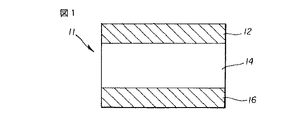
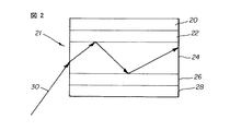
本発明の目的上、図1に示すステップ型導波路11は、透明コア14を有し、上側ではクラッド12によって、下側ではクラッド16によって取り囲まれている。これらのクラッド12,16は、透明コアよりも屈折率が低く、ブラックライト吸収性材料を含み、接着剤も含む。コアの屈折率はいずれのクラッドよりも高い。クラッド12及び16が、ほぼ同じ屈折率を有していることが好ましい。図1に示す導波路は、透明コア14では一貫して均一な屈折率を有し、そしてクラッド12及び16では、透明コアよりも低いがしかし均一な屈折率を有している。図2に示す別のタイプの導波路の場合、透明コア24のそれぞれの側に、クリアな上側クラッド層22と、クリアな下側クラッド層26とが設けられている。層22及び26はコア24よりも屈折率が低い。クラッドキャップ層20及び28は、黒色接着剤層である。
For the purpose of the present invention, the
図2に示すように、光線30が導波路のコアに入射すると、この光線は、コア24と上側クラッド22とによって形成された界面まで進む。クラッド22がコア24よりも屈折率が低く、光が臨界角未満である場合、この光はコアの方に全内部反射され、その光は、次いでコア24と下側クラッド26との界面に当たるまで伝搬する。こうして、この光は複数のセグメントに分かれ、これらのセグメントはクラッドで反射され、透明コア中を伝搬する。この光は反射される前に短い距離だけクラッド内を進む。光散乱を引き起こすおそれのある粗さ又は大きな粒子が存在する場合、光の一部は失われ、反射してコア24内に戻らない。このことは導波路の効率を低下させる。
As shown in FIG. 2, when the
簡単な表現で、導波路の動作は、図3を参照することにより部分的に理解することができる。導波路に入射する光波は屈折させられてクラッド内に入り、減衰(吸収)されるか、又は、コア/クラッド境界で全内部反射させられる。このようにして、光は導波路の長手方向に沿って伝搬する。光が透明コアに入射して全内部反射によって伝搬することができる最大角度を受光角と呼ぶ。図3は、層状粒子の濃度勾配を有する勾配導波路である。この導波路の中心における層状粒子濃度は、外面における層状粒子濃度よりも低い。その結果、光が中心から外面に進むにつれて、濃度は漸増し、従って屈折率は漸進的に低下する。屈折率が徐々に変化するので、光は中心に向かって向き直されるにつれて、ゆっくりと曲げられることになる。このようなデバイスは損失が少なくなり、従って、導波路に入射する光のより多くを透過させることになる。 In simple terms, the operation of the waveguide can be partially understood by referring to FIG. Light waves incident on the waveguide are refracted into the cladding and are attenuated (absorbed) or totally internally reflected at the core / cladding interface. In this way, light propagates along the length of the waveguide. The maximum angle at which light can enter the transparent core and propagate by total internal reflection is called the acceptance angle. FIG. 3 shows a gradient waveguide having a concentration gradient of layered particles. The layered particle concentration at the center of the waveguide is lower than the layered particle concentration on the outer surface. As a result, as the light travels from the center to the outer surface, the concentration gradually increases, and thus the refractive index gradually decreases. As the refractive index changes gradually, the light will be bent slowly as it is redirected toward the center. Such a device will have lower losses and thus will transmit more of the light incident on the waveguide.
このように、コア40内に勾配屈折率を有する導波路41は、勾配屈折率導波路である。光線44は空気又はその他の媒体から導波路に入射し、そして光線42は、導波路の長手方向に沿って伝搬するに従って、徐々にコア内で旋回させられる。上側クラッド層46は、勾配コアよりも屈折率が低く、ブラックライト吸収性材料を含み、接着剤も含む。下側クラッド48は、勾配コアよりも屈折率が低く、ブラックライト吸収性材料を含み、接着剤も含む。
Thus, the
材料に入射する光の挙動は、基本的にはその材料の特性によって制御される。おそらく、導波にとって最も重要な特性は、屈折率という語であると考えられる。ある材料の屈折率は、媒体中での電磁波伝搬速度に対する真空中での電磁波伝搬速度の比である。ある物質の屈折率(n)は、
n=Vv/V
のように定義される。この式中、Vvは真空中での光速であり、Vは物質中での光速である。一般的に、光は物質に入射すると速度が減少し、従って屈折率は常に1よりも大きくなる。たいていの材料の屈折率は1.32〜2.40であり、1.40〜1.80の値が本発明にとって最も妥当である。なお、幾種かの材料の屈折率は全ての方向において必ずしも同じでないことに注意すべきである。材料の内部対称性は、層内での原子の配向性を反映したものである。原子の配列は、光がどの程度に材料と相互作用するかを決定する。挙動の2つの基本タイプを示す:
1. 等方性−光が結晶のどこで入射するかとは無関係に、全ての方向における同じ特性(屈折率)が、同じ物理特性を示す。
2. 異方性−異なる方向において異なる特性(異なる屈折率)を有する。これらの材料は、シートの長手方向及び幅方向において2つの屈折率を有する一軸性材料であるか、又は、3つの屈折率によって特徴付けられる二軸性材料である。これらの材料は、材料の厚さ方向に広がる平面内に第3の屈折率を加える。
The behavior of light incident on a material is basically controlled by the properties of the material. Perhaps the most important property for waveguiding is the term refractive index. The refractive index of a material is the ratio of the speed of propagation of an electromagnetic wave in a vacuum to the speed of propagation of the electromagnetic wave in a medium. The refractive index (n) of a substance is
n = V v / V
Is defined as In this equation, V v is the speed of light in a vacuum, and V is the speed of light in a substance. In general, the speed of light as it impinges on a substance decreases, so that the refractive index is always greater than one. Most materials have a refractive index between 1.32 and 2.40, with values between 1.40 and 1.80 being most relevant for the present invention. It should be noted that the refractive index of some materials is not necessarily the same in all directions. The internal symmetry of the material reflects the orientation of the atoms in the layer. The arrangement of the atoms determines how light interacts with the material. Shows two basic types of behavior:
1. Isotropic-The same property (refractive index) in all directions shows the same physical property, regardless of where the light is incident on the crystal.
2. Anisotropy-has different properties (different refractive indices) in different directions. These materials are uniaxial materials having two indices in the longitudinal direction and width direction of the sheet, or biaxial materials characterized by three indices. These materials add a third refractive index in a plane extending in the thickness direction of the material.
導波路に入射する光はスネルの法則に従う。幾何光学のスネルの法則は、屈折境界、例えば空気−ガラス界面又は2つの異種ポリマーの界面に、非垂直角度で光線が当たるときに生じる曲げの量を規定する。スネルの法則についての下記の論議において、naは、光線が伝搬する材料の屈折率であり、αは、光線が境界に当たる際の、屈折境界での法線に対する光線の角度であり、nrは、屈折光線が伝搬する材料の屈折率であり、そしてβは、屈折光線が伝搬する際の、屈折境界での法線に対する光線の角度である。光線及び屈折光線は、同一平面内を、入射点における法線の両側で伝搬する。光線が低屈折率の材料から高屈折率の媒体中に伝搬する場合、この光線は法線に向かって曲げられる。光線が高屈折率の媒体から低屈折率の媒体中に伝搬する場合、この光線は法線から離れる方向に曲げられる。光線が高屈折率の材料内を低屈折率の材料に向かって、スネルの法則によれば屈折光線の正弦が1よりも大きいこと(数学的に不可能)が要求されるような角度で伝搬する場合、結果として、「屈折」光線は実際には反射光線となり、入射角と等しい角度で全反射して高屈折率媒体に戻される(従って依然としてスネルの法則に「従っている」)。この反射は、金属製反射性コーティング(例えばアルミニウム又は銀)が存在しなくても発生する。この現象は全内部反射と呼ばれる。全内部反射が発生する際の、屈折境界における法線に対する最小入射角は臨界角と呼ばれる。換言すれば全内部反射は、高屈折率材料内の光が低屈折率の媒体との界面に、(法線に対して)臨界角以上の入射角で衝突するときに発生する反射である。
スネルの法則 na *sin α=nr *sin β
Light incident on a waveguide obeys Snell's law. Snell's law of geometric optics defines the amount of bending that occurs when a light beam strikes a refractive boundary, for example, an air-glass interface or the interface of two dissimilar polymers, at a non-perpendicular angle. In the following discussion of Snell's law, n a is the index of refraction of the material through which the ray propagates, α is the angle of the ray relative to the normal at the refraction boundary when the ray hits the boundary, and n r Is the index of refraction of the material through which the refracted ray propagates, and β is the angle of the ray with respect to the normal at the refraction boundary as the refracted ray propagates. The ray and the refracted ray propagate in the same plane on both sides of the normal at the point of incidence. When a light ray propagates from a low index material into a high index medium, it is bent towards the normal. When a light ray propagates from a high index medium into a low index medium, it is bent away from the normal. The ray propagates through the high index material towards the low index material at an angle such that according to Snell's law, the sine of the refracted ray must be greater than 1 (mathematically impossible). If so, the result is that the "refractive" ray is actually a reflected ray, which is totally internally reflected at an angle equal to the angle of incidence and returned to the high index medium (and is therefore still "following"Snell's law). This reflection occurs even in the absence of a metallic reflective coating (eg, aluminum or silver). This phenomenon is called total internal reflection. The minimum angle of incidence relative to the normal at the refraction boundary when total internal reflection occurs is called the critical angle. In other words, total internal reflection is reflection that occurs when light in a high refractive index material impinges on an interface with a low refractive index medium at an angle of incidence greater than or equal to a critical angle (relative to the normal).
Snell's law n a * sin α = n r * sin β
入射角は、屈折境界で法線を基準に測定される。臨界角では、屈折は生じないので、β=90であり、sin β=1である。従って臨界角は、
αc=sin-1(nr/na)
によって示される。この式中、αcは臨界角であり、nrは密度が低い方の材料の屈折率であり、naは密度が高い方の媒体の屈折率である。
The angle of incidence is measured relative to the normal at the refractive boundary. At the critical angle, there is no refraction, so β = 90 and sin β = 1. Therefore, the critical angle is
α c = sin −1 (n r / n a )
Indicated by This wherein, alpha c is the critical angle, n r is the refractive index of the material towards a lower density, n a is the refractive index of the density higher medium.
幾何光学は、光線に関して光伝搬を記述する光学の一分野である。光線は2つの異なる材料間の界面で曲げられる。屈折した光線は、その光線が伝搬する材料との相互作用の結果として、速度が変化した光線であるか、又は一般的には、速度及び方向の両方が変化した光線である。 Geometric optics is a branch of optics that describes light propagation in terms of light rays. The light beam is bent at the interface between two different materials. A refracted ray is a ray that has changed velocity, or, generally, both velocity and direction, as a result of its interaction with the material it propagates.
光の速度は一定ではない。光の速度は、光が異なる透明物質を通過する際に変化する。光の空気中での伝搬速度は、何もない空間の真空中での伝搬速度よりも遅く、光の水中での伝搬速度は、空気中での伝搬速度よりも遅く、石英中での伝搬速度及びダイヤモンド中での伝搬速度はさらに遅い。光の速度は、その波長とその周波数とを掛け算したものに等しい。光が異種物質又は材料(ポリマー)を通過すると、その周波数は一定のままであり、その波長が変化する。互いに異種材料間の界面で波長(速度)がこのように変化することにより、一方の材料を通って他方の材料内に入る光は曲げられる。 The speed of light is not constant. The speed of light changes as it passes through different transparent materials. The propagation speed of light in air is lower than that in vacuum in an empty space, the speed of light in water is lower than the speed of propagation in air, and the speed of propagation in quartz. And the propagation speed in diamond is even slower. The speed of light is equal to its wavelength multiplied by its frequency. When light passes through a foreign substance or material (polymer), its frequency remains constant and its wavelength changes. This change in wavelength (velocity) at the interface between dissimilar materials causes light that passes through one material and into the other to bend.
いかなる物質の屈折率も、その物質中での光速に対する真空中での光速の比である。屈折率はまた、屈折角の正弦に対する入射角の正弦の比でもある(ASTM D642)。幾つかの典型的な材料の屈折率は下記の通りである:
フルオロカーボン(FEP) 1.34
ポリテトラフルオロエチレン(TFE) 1.35
クロロトリフルオロエチレン(CTFE) 1.42
プロピオン酸セルロース 1.46
酢酪酸セルロース 1.46〜1.49
酢酸セルロース 1.46〜1.50
メチルペンテンポリマー 1.485
エチルセルロース 1.47
アセタールホモポリマー 1.48
アクリル樹脂 1.49
硝酸セルロース 1.49〜1.51
ポリプロピレン(未変性) 1.49
ポリアロマー 1.492
ポリブチレン 1.50
アイオノマー 1.51
ポリエチレン(低密度) 1.51
ナイロン(PA)II型 1.52
アクリル系マルチポリマー 1.52
ポリエチレン(中密度) 1.52
スチレンブタジエン熱可塑性樹脂 1.52〜1.55
PVC(硬質) 1.52〜1.55
ナイロン(ポリアミド)6/6型 1.53
ユリアホルムアルデヒド 1.54〜1.58
ポリエチレン(高密度) 1.54
スチレンアクリロニトリルコポリマー 1.56〜1.57
ポリスチレン 1.57〜1.60
ポリカーボネート(充填剤なし) 1.586
ポリスチレン 1.59
ポリスルホン。
この情報から判るように、導波に使用され得る多くのポリマーは、互いにかなり近い屈折率を有する。
The refractive index of any material is the ratio of the speed of light in vacuum to the speed of light in that material. The index of refraction is also the ratio of the sine of the angle of incidence to the sine of the angle of refraction (ASTM D642). The refractive indices of some typical materials are as follows:
Fluorocarbon (FEP) 1.34
Polytetrafluoroethylene (TFE) 1.35
Chlorotrifluoroethylene (CTFE) 1.42
Cellulose propionate 1.46
Cellulose acetate butyrate 1.46 to 1.49
Cellulose acetate 1.46 to 1.50
Methylpentene polymer 1.485
Ethyl cellulose 1.47
Acetal homopolymer 1.48
Acrylic resin 1.49
Cellulose nitrate 1.49 to 1.51
Polypropylene (unmodified) 1.49
Polyallomer 1.492
Polybutylene 1.50
Ionomer 1.51
Polyethylene (low density) 1.51
Nylon (PA) II type 1.52
Acrylic multipolymer 1.52
Polyethylene (medium density) 1.52
Styrene butadiene thermoplastic resin 1.52 to 1.55
PVC (hard) 1.52 to 1.55
Nylon (polyamide) 6/6 type 1.53
Urea formaldehyde 1.54 to 1.58
Polyethylene (high density) 1.54
Styrene acrylonitrile copolymer 1.56 to 1.57
Polystyrene 1.57-1.60
Polycarbonate (without filler) 1.586
Polystyrene 1.59
Polysulfone.
As can be seen from this information, many polymers that can be used for waveguiding have refractive indices that are fairly close to each other.
導波路のコアとクラッドとの間の屈折率差が大きくなるにつれて、導波路に入射する光の受光角が大きくなる。すなわち、急角度からの入射光は吸収されずに全内部反射させることができる。コアとクラッドとの間の屈折率差が小さくなればなるほど、全内部反射させられる光は少なくなる。適合性のある材料の選択は限られているので、このことは重要になる。背面投影又はその他の用途に対して導波路を有用にするために、コアとクラッド材料とを互いに接着させなければならない。さらに、黒色色素又は顔料をクラッド内に含めることが望ましい。互いに接着し、しかも最適な屈折率差を有する材料を見出すのは難しい。 (4) As the refractive index difference between the core and the clad of the waveguide increases, the light receiving angle of light incident on the waveguide increases. That is, incident light from a steep angle can be totally internally reflected without being absorbed. The smaller the refractive index difference between the core and the cladding, the less light will be totally internally reflected. This is important because the choice of compatible materials is limited. In order for the waveguide to be useful for rear projection or other applications, the core and cladding materials must be glued together. Further, it is desirable to include a black dye or pigment in the cladding. It is difficult to find materials that adhere to each other and yet have an optimal refractive index difference.
さらに、注意すべきことは、スクリーンの観察側から導波路に入射する周囲室内光をも最低限に抑えるように背面投影スクリーン用の導波路の性能を最適化するためには、コアとクラッドとの間の屈折率差を制御しなければならないということである。未変性ポリマーのこの用途に対する汎用性は制限されている。ポリマーの屈折率を制御又は改変する能力を得ることは、導波路スクリーンの設計時に極めて重要かつ有用である。驚くべきことに、ポリマーマトリックス中の粘土のようなナノ粒子の濃度を、理に適った範囲で制御することにより、ポリマーと粘土との間の屈折率が無限に制御されることが判った。本発明の粘土は、ポリマーの屈折率を低下させることに役立つ。この場合、コアとクラッドとに同じポリマーを使用することができ、従って接着の問題を懸念することはなくなる。さらに、光エンジンからの入射光受光角及び観察側からの周囲室内光の両方の制御を最適化することができる。層内で濃度勾配を成すように粘土を形成することにより、又は、濃度が僅かに変化する極めて薄い複数の層を形成することにより、デルタ屈折率の大きい単一層が中心コアと対を成しているようなステップ型導波路よりも損失の少ない導波路を形成することができる。このような発見により、コアとクラッドとに用いられる異なるポリマーの屈折率を改変することも可能になる。 Furthermore, it should be noted that in order to optimize the performance of the waveguide for the rear projection screen so that the ambient room light entering the waveguide from the viewing side of the screen is also minimized, the core and cladding must be combined. That is, the refractive index difference between the two must be controlled. The versatility of unmodified polymers for this application is limited. Obtaining the ability to control or modify the refractive index of a polymer is extremely important and useful in designing waveguide screens. Surprisingly, it has been found that by controlling the concentration of nanoparticles, such as clay, in a polymer matrix within a reasonable range, the refractive index between the polymer and the clay is infinitely controlled. The clays of the present invention help reduce the refractive index of the polymer. In this case, the same polymer can be used for the core and the cladding, so that there is no concern about adhesion problems. Further, it is possible to optimize the control of both the angle of acceptance of the incident light from the light engine and the ambient room light from the observation side. A single layer with a large delta refractive index is paired with the central core by forming the clay to form a concentration gradient within the layer, or by forming very thin layers with slightly varying concentrations. It is possible to form a waveguide having less loss than the step-type waveguide described above. Such findings also allow the refractive index of the different polymers used for the core and cladding to be modified.
以下に示す用語は、本明細書中で使用される場合にはいつでも下記の意味を有する。
コアとは、透明材料から成る1又は2以上の層を意味する。
クラッド若しくはクラッディング又はクラッド層とは、透明コアに隣接するか又は別のクラッド層に隣接する層であって、中心コアよりも屈折率が低い層を意味する。
ステップ・インデックス・クラッド型とは、均一ではあるがしかし透明コアよりも低い屈折率を有する層を意味する。
勾配屈折率とは、層の片側から他方の側に向かって変化する屈折率を意味する。
The terms set forth below, whenever used herein, have the following meanings.
By core is meant one or more layers of a transparent material.
By cladding or cladding or cladding layer is meant a layer that is adjacent to the transparent core or another cladding layer and has a lower refractive index than the central core.
By step index cladding is meant a layer that is uniform but has a lower refractive index than the transparent core.
Gradient refractive index means a refractive index that changes from one side of the layer to the other.
高分子チャネルとは、光を伝搬するのに使用できる1又は2以上の層を意味する。
「ナノ複合材料」とは、少なくとも1種の成分が、0.1〜100ナノメートルの範囲内の少なくとも1つの寸法を有する無機相、例えばスメクタイト粘土を含む複合材料を意味する。
「平板状体(plates)」とは、第3の寸法よりもかなり大きい2つの同等な寸法を有する粒子を意味する。
「層状物質」とは、複数の隣接して結合した層の形態にあるスメクタイト粘土のような無機物質を意味する。
「小板状体(platelets)」とは、層状物質の個々の層を意味する。
「インターカレーション」とは、層状物質の小板状体間に1つ以上の異物分子又は異物分子の一部が挿入することを意味し、通常は米国特許第5,554,670号明細書に示されているようなX線回折技術により検出される。
「インターカラント」とは、前記層状物質の小板状体間に装入される前述の異物分子を意味する。
「膨潤(exfoliation)」又は「層間剥離(delamination)」とは、個々の小板状体が分離して、積層秩序のない無秩序な構造になることを意味する。
「ポリマー」は、オリゴマー、コポリマー及びインターポリマーをも包含することとする。
「アイオノマー」とは、イオン結合及び共有結合で連結されているポリマーである。アイオノマー中には、互いに結合した正の電荷を帯びた基と負の電荷を帯びた基とが存在し、その極性が独特の樹脂を形成する。
「有機変性された」とは、有機物質又は有機末端基を加えることを意味する。
By polymeric channel is meant one or more layers that can be used to propagate light.
By "nanocomposite" is meant a composite wherein at least one component comprises an inorganic phase having at least one dimension in the range of 0.1 to 100 nanometers, such as a smectite clay.
By "plates" is meant particles having two equivalent dimensions that are substantially larger than the third dimension.
By "layered material" is meant an inorganic material such as smectite clay in the form of a plurality of adjacent bonded layers.
"Platelets" means individual layers of a layered material.
"Intercalation" means the insertion of one or more foreign molecules or portions of foreign molecules between platelets of a layered material, usually as shown in U.S. Patent No. 5,554,670. Detected by X-ray diffraction techniques such as
The term “intercalant” means the above-described foreign molecule charged between the platelets of the layered material.
By "exfoliation" or "delamination" is meant that individual platelets separate into a disordered structure without stacking order.
"Polymer" shall also include oligomers, copolymers and interpolymers.
An "ionomer" is a polymer that is linked by ionic and covalent bonds. In the ionomer, there are a positively charged group and a negatively charged group bonded to each other, and their polarities form a unique resin.
“Organically modified” means adding an organic substance or organic end group.
米国特許第4,739,007号、第4,810,734号、第4,889,885号、第4,894,411号、第5,102,948号、第5,164,440号、第5,164,460号、第5,248,720号、第5,973,053号及び第5,578,672号の各明細書に記載されているようなフィロシリケートが、入手容易性及びコストの理由から、本発明にとって好ましい層状粒子である。特に好ましいフィロシリケートは、所望の屈折率値を有する理由から、フッ素化されたフィロシリケートである。スメクタイト粘土、例えばナトリウムモンモリロナイト及びカルシウムモンモリロナイトのようなフィロシリケートは有機分子、例えばアンモニウムイオンで処理して、隣接する平面状シリケート層間にこれらの有機分子をインターカレートし、及び/又は、個々のシリケート層を膨潤させることができることが知られている。これらのシリケート層は、ホストポリマーの重合前、重合後又は重合中にホストポリマーと混合されると、そのポリマーの1つ以上の特性、例えば機械的強度特性及び/又は高温特性を改善することが判っている(米国特許第4,739,007号明細書、同第4,810,734号明細書及び同第5,385,776号明細書参照)。本発明に適したフィロシリケートとしては、スメクタイト粘土、例えばモンモリロナイト、具体的にはナトリウムモンモリロナイト、マグネシウムモンモリロナイト及び/又はカルシウムモンモリロナイト、ノントロナイト(nontronite)、バイデライト(beidellite)、ボルコンスコアイト(volkonskoite)、ヘクトライト(hectorite )、サポナイト(saponite)、ソーコナイト(sauconite)、ソボカイト(sobockite)、スティーブンサイト(stevensite)、スビンフォルダイト(svinfordite )、バーミキュライト(vermiculite)、マガディアイト(magadiite)、ケニヤアイト(kenyaite)、タルク(talc)、雲母(mica)、カオリナイト(kaolinite )及びこれらの混合物が挙げられる。 U.S. Pat.Nos. 4,739,007, 4,810,734, 4,889,885, 4,894,411, 5,102,948, 5,164,440, 5,164,460, 5,248,720, 5,973,053, and 5,578,672. Such phyllosilicates are preferred layered particles for the present invention for reasons of availability and cost. Particularly preferred phyllosilicates are fluorinated phyllosilicates because they have the desired refractive index value. Smectite clays, such as phyllosilicates such as sodium montmorillonite and calcium montmorillonite, are treated with organic molecules, such as ammonium ions, to intercalate these organic molecules between adjacent planar silicate layers and / or individual silicates. It is known that the layers can swell. These silicate layers can improve one or more properties of the host polymer, such as mechanical strength properties and / or high temperature properties, when mixed with the host polymer before, after, or during polymerization of the host polymer. (See U.S. Pat. Nos. 4,739,007, 4,810,734 and 5,385,776). Suitable phyllosilicates for the present invention include smectite clays, such as montmorillonite, specifically sodium montmorillonite, magnesium montmorillonite and / or calcium montmorillonite, nontronite, beidellite, volkonskoite, Hectorite (hectorite), saponite (saponite), saconite (sauconite), sobockite (sobockite), stevensite (stevensite), svinfoldite (svinfordite), vermiculite (vermiculite), magadiite (magadiite), Kenyaite (kenyaite), Examples include talc, mica, kaolinite and mixtures thereof.
他の有用な粘土系層状粒子としては、イライト(illite)、混合層状イライト/スメクタイト鉱物、例えばレディカイト(ledikite)、及び、イライトと上記粘土鉱物との混合物が挙げられる。前述の粘土系材料は関連文献、例えば"Clay Colloid Chemistry"(H. van Olphen著、第2版、John Wiely & Sons Publishers発行(1977))に詳細に記載されている。アニオン系ポリマーと共に特に有用なその他の有用な層状粒子は、層状のヒドロタルサイト又は複水酸化物、例えばMg6Al3.4(OH)18.8(CO3)1.7H2Oである。この物質は正の電荷を帯びた層と、層間空間内に交換可能なアニオンを有する。さらに他の有用な層状粒子としては、塩化物、例えばFeCl3、FeOCl、カルコゲナイド、例えばTiS2、MoS2及びMoS3、シアン化物、例えばNi(CN)2、及び酸化物、例えばH2Si2O5、V6O13、HTiNbO5、Cr0.5V0.5S2、V2O5、AgをドープしたV2O5、W0.2V2.8O7、Cr3O8、MoO3(OH)2、VOPO4・2H2O、Zr(HPO4)2・2H2O、CaPO4CH3・H2O、MnHAsO4・H2O、及びAg6Mo10O33が挙げられる。 Other useful clay-based layered particles include illite, mixed layered illite / smectite minerals, such as ledikite, and mixtures of illite with the above clay minerals. The above-mentioned clay-based materials are described in detail in the related literature, for example, "Clay Colloid Chemistry" (H. van Olphen, 2nd edition, published by John Wiely & Sons Publishers (1977)). Particularly useful Other useful layered particles with anionic polymers, hydrotalcites or double hydroxides of layer, for example, Mg 6 Al 3.4 (OH) 18.8 (CO 3) is 1.7 H 2 O. This material has a positively charged layer and exchangeable anions in the interlayer space. Still other useful layered particles include chlorides, for example FeCl 3, FeOCl, chalcogenides, such as TiS 2, MoS 2 and MoS 3, cyanides, for example Ni (CN) 2, and oxides such as H 2 Si 2 O 5, V 6 O 13, HTiNbO 5, Cr 0.5 V 0.5 S 2, V 2 O 5, V 2 O 5 doped with Ag, W 0.2 V 2.8 O 7 , Cr 3 O 8, MoO 3 (OH) 2 , VOPO 4 · 2H 2 O, Zr (HPO 4) 2 · 2H 2 O, CaPO 4 CH 3 · H 2 O, MnHAsO 4 · H 2 O, and Ag 6 Mo 10 O 33 and the like.
特に好ましい層状粒子は、フッ素化された粒子である。なぜならば、それらの粒子は望ましい低い屈折率値を有するからである。好ましい層状粒子は膨張可能であり、これにより、他の作用物質、例えばイオン又は分子が、層状粒子にインターカレートし、及び/又は層状粒子を膨潤させて、その結果、無機相の望ましい分散体をもたらすことができるものである。これらの膨張可能な層状粒子としては、2:1型のフィロシリケートが挙げられる。これらのフィロシリケートは層上の負電荷と層間空間内に相応数の交換可能なカチオンとを有し、これにより全体的な電荷中立性を維持する。100g当たり50〜300ミリ当量のカチオン交換能を有する典型的なフィロシリケートが好ましい。本発明に対して非常に好ましい層状粒子としては、スメクタイト粘土、例えばモンモリロナイト、ノントロナイト、バイデライト、ボルコンスコアイト、ヘクトライト、サポナイト、ソーコナイト、ソボカイト、スティーブンサイト、スビンフォルダイト、ハロイサイト、マガディアイト、ケニヤアイト及びバーミキュライト、並びにヒドロタルサイト、カルコゲナイト及び酸化物が挙げられる。 Particularly preferred layered particles are fluorinated particles. Because the particles have a desirable low refractive index value. Preferred lamellar particles are swellable, whereby other agents, such as ions or molecules, can intercalate into the lamellar particles and / or swell the lamellar particles, so that the desired dispersion of the inorganic phase Can bring about. These expandable layered particles include 2: 1 phyllosilicates. These phyllosilicates have a negative charge on the layer and a corresponding number of exchangeable cations in the interlayer space, thereby maintaining overall charge neutrality. Typical phyllosilicates having a cation exchange capacity of 50-300 meq / 100 g are preferred. Highly preferred layered particles for the present invention include smectite clays such as montmorillonite, nontronite, beidellite, vorconite, hectorite, saponite, sauconite, sobokite, stevensite, subinfoldite, halloysite, magadiite, Kenyaite and vermiculite, as well as hydrotalcite, chalcogenite and oxides.
前述のスメクタイト粘土は天然物であっても合成物であってもよい。この違いは、粒度及び/又は付随する不純物のレベルに影響を及ぼし得る。典型的には、合成粘土は横方向寸法がより小さく、従って、アスペクト比がより小さい。しかし、合成粘土は天然粘土と比較して、より純粋であり、より狭い粒度分布を有しており、更なる精製又は分離を必要としない。本発明の場合、粘土粒子の横方向寸法は0.01μm〜1μm、好ましくは0.01μm〜0.05μmであるのがよい。粘土粒子の厚さ又は鉛直方向寸法は、様々な値をとり得るが、0.5nm〜10nm、好ましくは1nm〜5nmである。粘土粒子の最大寸法と最小寸法との比であるアスペクト比は、本発明の場合、少なくとも10:1であり最大で1000:1であるのがよい。粒子の粒度及び形状に関する前述の制限は、ナノ複合材料のいくつかの特性を他の特性に悪影響を及ぼさずに適切に改良する。例えば横方向寸法が大きいと、機械的特性及びバリアー特性の向上にとって望ましい1つの尺度であるアスペクト比の増大をもたらすことがある。しかしながら、非常に大きな粒子は、光学的な欠点、例えば曇りをもたらすことがあり、また、処理装置、運搬装置及び仕上げ装置に対して摩耗作用を生じるおそれがある。10:1未満のアスペクト比は、達成するのが難しく、費用が嵩む割には効用が限られる。本発明の粘土の好ましいアスペクト比は、最適な特性を得ることを目的として、20:1〜200:1である。 The above-mentioned smectite clay may be a natural product or a synthetic product. This difference can affect the particle size and / or level of accompanying impurities. Typically, synthetic clays have smaller lateral dimensions and, therefore, smaller aspect ratios. However, compared to natural clays, synthetic clays are purer, have a narrower particle size distribution, and do not require further purification or separation. In the case of the present invention, the clay particles have a lateral dimension of 0.01 μm to 1 μm, preferably 0.01 μm to 0.05 μm. The thickness or vertical dimension of the clay particles can take various values, but is 0.5 nm to 10 nm, preferably 1 nm to 5 nm. The aspect ratio, which is the ratio of the largest dimension to the smallest dimension of the clay particles, is in the present invention at least 10: 1 and up to 1000: 1. The foregoing limitations on particle size and shape appropriately improve some properties of the nanocomposite without adversely affecting other properties. For example, a large lateral dimension can result in an increase in aspect ratio, which is one measure that is desirable for improved mechanical and barrier properties. However, very large particles can lead to optical defects, such as fogging, and can cause abrasion effects on processing, transport and finishing equipment. Aspect ratios less than 10: 1 are difficult to achieve and have limited utility at the expense of expense. The preferred aspect ratio of the clay of the present invention is between 20: 1 and 200: 1 for the purpose of obtaining optimal properties.
本発明において使用される粘土はオルガノ粘土(organoclay)であってよい。オルガノ粘土は官能化されていない粘土を好適なインターカラントと相互作用させることにより生成される。これらのインターカラントは、典型的には、中性又はイオン性の有機化合物である。有用な中性有機分子としては、極性分子、例えばアミド、エステル、ラクタム、ニトリル、尿素、炭酸塩、リン酸塩、ホスホン酸塩、硫酸塩、スルホン酸塩及びニトロ化合物などが挙げられる。中性有機インターカラントは、モノマー、オリゴマー又はポリマーであることができる。中性有機分子は、元の電荷を均衡するイオンの完全な交換を生じずに、水素結合を介して粘土の層中へのインターカレーションを引き起こすことができる。有用なイオン性化合物は、オニウム化学種、例えば脂肪族、芳香族又はアリール脂肪族アミン類、ホスフィン類及びスルフィド類のアンモニウム(第1級、第2級、第3級及び第4級)、ホスホニウム又はスルホニウム誘導体などのカチオン系界面活性剤である。典型的には、オニウムイオンは、好ましいスメクタイト粘土の金属カチオンとイオン交換することにより、層中へのインターカレーションを引き起こすことができる。様々な工業用のオルガノ粘土が粘土製造供給元、例えばSouthern Clay Products及びNanocorから入手することができ、これらを本発明の実施に使用することができる。 粘土 The clay used in the present invention may be an organoclay. Organoclays are formed by interacting an unfunctionalized clay with a suitable intercalant. These intercalants are typically neutral or ionic organic compounds. Useful neutral organic molecules include polar molecules such as amides, esters, lactams, nitriles, ureas, carbonates, phosphates, phosphonates, sulfates, sulfonates and nitro compounds. Neutral organic intercalants can be monomers, oligomers or polymers. Neutral organic molecules can cause intercalation into the clay layer via hydrogen bonding without complete exchange of the ions that balance the original charge. Useful ionic compounds include onium species such as aliphatic (aromatic or arylaliphatic amines, phosphines and sulfides ammonium (primary, secondary, tertiary and quaternary), phosphonium Or a cationic surfactant such as a sulfonium derivative. Typically, onium ions can cause intercalation into the layer by ion exchange with the metal cations of the preferred smectite clay. A variety of industrial organoclays are available from clay manufacturers such as Southern Clay Products and Nanocor and can be used in the practice of the present invention.
本発明のスメクタイト粘土はさらに、相溶化剤で処理することもできる。相溶化剤の目的は、無機粘土相を、粘土が好ましくは分散されるバインダーポリマーと相溶化させることである。典型的には、相溶化剤は、粘土表面と結合する成分と、バインダーポリマーと好ましく相互作用する別の成分とを含む。効果的な相溶化により、バインダーポリマー中に粘土が均質に分散される。 ス The smectite clay of the present invention can be further treated with a compatibilizer. The purpose of the compatibilizer is to compatibilize the inorganic clay phase with a binder polymer in which the clay is preferably dispersed. Typically, the compatibilizer comprises a component that binds to the clay surface and another component that preferably interacts with the binder polymer. Effective compatibilization results in homogeneous dispersion of the clay in the binder polymer.
インターカラント、及びインターカラントであることも可能な相溶化剤は、選択された特定のポリマー及び特定の粘土物質に応じて多種多様であってよい。本発明の好ましいスメクタイト粘土を処理するのに有用な種々のタイプのインターカラント及び相溶化剤の例は、米国特許第4,739,007号、第4,810,734号、第4,889,885号、第4,894,411号、第5,102,948号、第5,164,440号、第5,164,460号、第5,248,720号、第5,973,053号、第5,578,672号、第5,698,624号、第5,760,121号、第5,804,613号、第5,830,528号、第5,837,763号、第5,844,032号、第5,877,248号、第5,880,197号、第6,057,396号、第5,384,196号、第5,385,776号、第5,514,734号、第5,747,560号、第5,780,376号、第6,036,765号、第6,034,163号、第6,084,019号及び第5,952,093号の各明細書の開示に含まれているが、それらの開示内容に限定されるわけではない。 Intercalants, and compatibilizers, which can also be intercalants, can vary widely depending on the particular polymer selected and the particular clay material. Examples of various types of intercalants and compatibilizers useful in treating the preferred smectite clays of the present invention are disclosed in U.S. Patent Nos. 4,739,007, 4,810,734, 4,889,885, 4,894,411, 5,102,948, No. No. 5,164,440, No. 5,164,460, No. 5,248,720, No. 5,973,053, No. 5,578,672, No. 5,698,624, No. 5,760,121, No. 5,804,613, No. 5,830,528, No. 5,837,763, No. 5,844,052, No. 5,877, No. 6,057,396, No. 5,384,196, No. 5,385,776, No. 5,514,734, No. 5,747,560, No. 5,780,376, No. 6,036,765, No. 6,034,163, No. 6,084,019 and No. 5,952,093. But is not limited to those disclosures.
本発明の光学要素は、多層粒子を含有する中心コアとして、光の伝搬のための透明高分子チャネルを含む。粒子の大部分は1μm未満の投影サイズと、1000:1〜10:1の範囲内の最長寸法対最小寸法のアスペクト比を有し、これらの粒子は、屈折率差が生じるように、光伝搬方向に対して垂直な平面の少なくとも一部に濃度差を成して配列される。このような光学要素の場合、吸光度を最小化し、光損失を最小限に抑えるように、光は案内される。このような要素は、光及び情報をその要素内の入口点から出口点に向けるか又は搬送するのに有用である。 光学 The optical element of the present invention includes a transparent polymer channel for light propagation as a central core containing multilayer particles. Most of the particles have a projected size of less than 1 μm and a longest-to-smallest aspect ratio in the range of 1000: 1 to 10: 1, such that the particles have a light propagating such that a refractive index difference occurs. At least a part of a plane perpendicular to the direction is arranged with a density difference. In such an optical element, light is guided to minimize absorbance and minimize light loss. Such elements are useful for directing or conveying light and information from entry points to exit points within the element.
本発明の一実施態様の場合、中心コアは1つの層から成っていてもよい。有用なコアは、中心コアの1又は2以上の側でクラッディングされていてもよい。典型的なクラッド層は、コアと同じか又はコアとは異なる階段状屈折率又は勾配屈折率を有することができる。導波の目的上、中心透明コアにおける勾配屈折率は、中心軸から外側に向かって減少する示差屈折率を有することが望ましい。クラッド層はクラッド層自体内で、屈折率の更なる階段状変化を有するか、又は勾配屈折率を有することができる。クラッドはポリマー、又はコアよりも屈折率が低いガラスのような材料であってよい。さらに、クラッドは、接着性のようなその他の機能性を有していてもよく、吸光性材料又は不透明な黒色材料を有することができる。 の 一 In one embodiment of the invention, the central core may consist of one layer. Useful cores may be clad on one or more sides of the central core. A typical cladding layer may have a stepped or gradient index that is the same as or different from the core. For waveguide purposes, it is desirable that the gradient index in the central transparent core have a differential index that decreases outward from the central axis. The cladding layer may have a further step change in the refractive index within the cladding layer itself or may have a gradient index. The cladding may be a polymer or a material such as glass with a lower refractive index than the core. In addition, the cladding may have other functionality, such as adhesion, and may have a light absorbing material or an opaque black material.
本発明において有用な中心コアはアーチ形であってよい。その場合、光学要素は、湾曲投影スクリーン、又は光を曲げるか又は配向するレンズ形デバイスとして使用できる。他の有用な光学要素は、例えば光ファイバー又はライトパイプのように円筒形である中心コアを有していてよい。このような要素は、ファイバー又は界面を他の光学要素と形状的に結合することができる光学カップリングとして使用できる。円筒形の光学要素の場合、円筒形コアの周囲を少なくとも1層のクラッド層が取り囲んでいてよい。 中心 The central core useful in the present invention may be arcuate. In that case, the optical element can be used as a curved projection screen, or a lenticular device that bends or directs light. Other useful optical elements may have a central core that is cylindrical, for example, an optical fiber or light pipe. Such an element can be used as an optical coupling that can formally couple a fiber or interface with another optical element. In the case of a cylindrical optical element, at least one cladding layer may surround the cylindrical core.
本発明のさらなる実施態様は、凸状、凹状又は複雑な形状であることができるレンズのように形作られた中心コアを有する光学要素を形成することができる。これらのレンズ形状の中心コア内及び/又はこのレンズ形状物と組み合わされたクラッド層内に勾配屈折率を提供することにより、レンズに入射した光をより良好に制御することができる。レンズに入射した光は屈折率変化を受け、その光がレンズに入射する前にその中を伝搬する媒体の屈折率よりもレンズの屈折率が高いか又は低いかに応じて、レンズに入射した光は、法線に向かって曲げられるか、或いは法線から離れる方向に曲げられる。同じことが、光がレンズから出て空気又は他の媒体中に入る際にも当てはまる。レンズが勾配屈折率を備えている場合には、光は鋭角を成して旋回するというよりはむしろ湾曲する傾向がある。このようなレンズは光を制御する上でより効率的である。なお、この勾配は、レンズの一部にだけ適用することにより、レンズの光制御能力をさらに向上させることができる。本発明において有用な他の光学要素は、レンズアレイを形成する中心コア、並びに、所定の幾何学的形状を形成することができるレンズアレイである。これらのタイプのアレイは、光配向シートとして有用である。この光配向シートにおいて、層状粒子によって所定の形状がさらに際立たされ、これにより、光旋回特性又は形状付与特性をより良好に改善することができる。
多層粒子は中心コアに、0〜90質量%で添加されてよい。0%では、屈折率勾配は本来の材料から始まり、勾配はコア内の層状粒子の濃度で形成することができる。層状粒子の濃度が増加するにつれて、屈折率はさらに減少する。なお、この中心コアと共に、更なる屈折率変化又は勾配屈折率変化をもたらすクラッドを使用することができる。
Further embodiments of the present invention can form an optical element having a central core shaped like a lens, which can be convex, concave or complex in shape. Providing a gradient index in the central core of these lens shapes and / or in the cladding layer associated with the lens shape allows for better control of light incident on the lenses. The light incident on the lens undergoes a change in the refractive index, and the light incident on the lens depends on whether the refractive index of the lens is higher or lower than that of a medium propagating therein before the light is incident on the lens. Are bent toward or away from the normal. The same is true as light exits the lens and enters air or other media. If the lens has a gradient index of refraction, the light will tend to bend rather than pivot at an acute angle. Such a lens is more efficient in controlling light. In addition, by applying this gradient to only a part of the lens, the light control ability of the lens can be further improved. Other optical elements useful in the present invention are a central core forming a lens array, as well as a lens array capable of forming a predetermined geometric shape. These types of arrays are useful as light directing sheets. In the photo-alignment sheet, the predetermined shape is further emphasized by the layered particles, whereby the light turning characteristics or the shape imparting characteristics can be improved more favorably.
The multilayer particles may be added to the central core at 0-90% by weight. At 0%, the refractive index gradient starts from the original material and the gradient can be formed by the concentration of lamellar particles in the core. As the concentration of the lamellar particles increases, the refractive index further decreases. It should be noted that a cladding providing a further refractive index change or gradient index change can be used with this central core.
本発明の好ましい実施態様において、光学要素は、光伝搬方向に対して垂直な平面内で、光チャネルの中心軸から離れるにつれて濃度が増加する濃度勾配を成す層状粒子を有する。このような実施態様が好ましい理由は、このような勾配により、屈折率の単一又は急激な変化を有する導波路よりも損失が少ない導波路が提供されるからである。この場合、光がコア内にとどまる。 In a preferred embodiment of the invention, the optical element comprises layered particles having a concentration gradient in a plane perpendicular to the direction of light propagation, the concentration increasing with distance from the central axis of the light channel. Such an embodiment is preferred because such a gradient provides a waveguide with less loss than a waveguide having a single or abrupt change in refractive index. In this case, the light stays in the core.
本発明において有用な濃度勾配は、一定の変化率又は指数関数的な変化率を有することができる。屈折率における非常に小さな一連の階段状変化が、勾配に近づいてもよい。本発明の実施態様において、1段当たりの屈折率変化が0.01未満である一連の階段状変化によって、勾配が形成される。このような一連の層状粒子が空気で加熱される(まだ液状であるときに)と、層状粒子は1つの層から次の層内に移動することができ、従って階段状から勾配へと、濃度が平準化される。 濃度 Concentration gradients useful in the present invention can have a constant or exponential rate of change. A very small series of step changes in the index of refraction may approach the slope. In an embodiment of the invention, the gradient is formed by a series of step changes in which the refractive index change per step is less than 0.01. When such a series of layered particles are heated with air (while still liquid), the layered particles can move from one layer into the next, thus increasing the concentration from a step to a gradient. Are leveled.
本発明の別の有用な実施態様は、中心コアから外縁部に向かって屈折率が減少する濃度勾配を提供する。このような光学要素はスクリーンの鉛直方向及び/又は水平方向の視野角を低減するための、ゲーム及びコンピュータのスクリーンに有用なプライバシー・スクリーンを提供する。このプライバシー・スクリーンは、スクリーンの隣に座っている他人が、スクリーン上に表示された情報を見るのを制約する。 有用 Another useful embodiment of the present invention provides a concentration gradient where the refractive index decreases from the central core to the outer edge. Such optical elements provide a privacy screen useful for games and computer screens to reduce the vertical and / or horizontal viewing angles of the screen. This privacy screen restricts others sitting next to the screen from seeing the information displayed on the screen.
本発明において有用な層状粒子は0.5〜10nmの厚さを有することができる。このような粒子の最大寸法と最小寸法とのアスペクト比は、10:1〜1000:1であることができる。粒子の粒度及び形状に関する前述の制限は、ナノ複合材料のいくつかの特性を他の特性に悪影響を及ぼさずに適切に改良する。例えば横方向寸法が大きいと、機械的特性及びバリアー特性の向上にとって望ましい1つの尺度であるアスペクト比の増大をもたらすことがある。しかしながら、非常に大きな粒子は、光学的な欠点、例えば曇りをもたらすことがあり、また、処理装置、運搬装置及び仕上げ装置に対して摩耗作用を生じるおそれがある。10:1未満のアスペクト比は、達成するのが難しく、費用が嵩む割には効用が限られる。本発明の粘土の好ましいアスペクト比は、最適な特性を得ることを目的として、20:1〜200:1である。 O Layered particles useful in the present invention can have a thickness of 0.5 to 10 nm. The aspect ratio between the largest and smallest dimensions of such particles can be from 10: 1 to 1000: 1. The foregoing limitations on particle size and shape appropriately improve some properties of the nanocomposite without adversely affecting other properties. For example, a large lateral dimension can result in an increase in aspect ratio, which is one measure that is desirable for improved mechanical and barrier properties. However, very large particles can lead to optical defects, such as fogging, and can cause abrasion effects on processing, transport and finishing equipment. Aspect ratios less than 10: 1 are difficult to achieve and have limited utility at the expense of expense. The preferred aspect ratio of the clay of the present invention is between 20: 1 and 200: 1 for the purpose of obtaining optimal properties.
本発明の光学要素において有用な層状粒子は、ヒドロタルサイト、フィロシリケート、スメクタイト、モンモリロナイト、ヘクトライトを含んでよい。これらの粒子及び粒子の利点については上述の通りである。さらに、スメクタイトは、合成のものであるか、又は粒子の屈折率特性をさらに高めるため、合成物であっても有機変性されたものであってもよい。モンモリロナイト系層状粒子はケイ酸アルミニウムを含んでよく、これに対してヘクトライト系粒子はケイ酸マグネシウムを含んでよい。 層 Lamellar particles useful in the optical element of the present invention may include hydrotalcite, phyllosilicate, smectite, montmorillonite, hectorite. These particles and the advantages of the particles are as described above. Further, the smectite may be synthetic or may be synthetic or organically modified to further enhance the refractive index properties of the particles. The montmorillonite-based layered particles may include aluminum silicate, whereas the hectorite-based particles may include magnesium silicate.
本発明の好ましい実施態様において、スメクタイト層状粒子及びヘクトライト層状粒子は、フッ素化されたものであってもよい。このような粒子は、フッ素化されていない粒子よりも屈折率が低く、従って、濃度勾配範囲を広げるか、又はより効率的な光制御を可能にする上で有用である。さらなる詳細は上述の通りである。 好 ま し い In a preferred embodiment of the present invention, the smectite layered particles and the hectorite layered particles may be fluorinated. Such particles have a lower index of refraction than non-fluorinated particles and are therefore useful in extending the concentration gradient range or allowing for more efficient light control. Further details are as described above.
本発明の有用な光学要素を提供するために、層状粒子は透明ポリマー中に分散され、この透明ポリマーは、それらの層状粒子を所定の位置に保持する。有用な透明ポリマーの透過百分率は70〜100%である。80%未満の透過百分率は通常あまり効率的ではなく、光を吸収するか又は散乱させる傾向がある。実質的に100%又は100%に近い透明ポリマーが最も望ましい。なぜならば光がポリマー中を伝搬する際の損失がほとんど又は全くないからである。あらゆるポリマーが、光の極めて僅かな一部を吸収するか又は散乱させ、従って100%透過率の達成は難しいことが認識されるべきである。 層 To provide a useful optical element of the present invention, the layered particles are dispersed in a transparent polymer, which holds the layered particles in place. Useful transparent polymers have a percent transmission of 70-100%. Percent transmission below 80% is usually less efficient and tends to absorb or scatter light. Transparent polymers substantially at or near 100% are most desirable. Because there is little or no loss as light propagates through the polymer. It should be appreciated that any polymer will absorb or scatter a very small portion of the light, and thus achieving 100% transmission will be difficult.
本発明の有用な透明ポリマーは、水溶性ポリマー、親水性コロイド及び水不溶性ポリマーから成る群から選択された少なくとも1種の材料を含むことができる。なお、透明ポリマーは、層状粒子を保持するためのバインダーポリマーとして作用することもできる。 The useful transparent polymers of the present invention can include at least one material selected from the group consisting of water-soluble polymers, hydrophilic colloids, and water-insoluble polymers. Note that the transparent polymer can also act as a binder polymer for holding the layered particles.
層状粒子、特にスメクタイト粘土が好ましくは分散されるバインダーポリマーは、種々多様なポリマーを含むことができる。具体的には、バインダーポリマーは、水性溶剤系又は有機溶剤系のコーティング組成物から適用するために、水溶性ポリマー、親水性コロイド又は水不溶性ポリマーを含むことができる。或いは、バインダーポリマーは、熱処理可能な溶融物から適用するために、熱処理可能な熱可塑性ポリマー又は熱硬化性ポリマーを含むこともできる。 バ イ ン ダ ー The binder polymer in which the layered particles, especially the smectite clay are preferably dispersed, can include a wide variety of polymers. Specifically, the binder polymer can include a water-soluble polymer, a hydrophilic colloid, or a water-insoluble polymer for application from an aqueous solvent-based or organic solvent-based coating composition. Alternatively, the binder polymer can include a heat-treatable thermoplastic or thermoset polymer for application from a heat-treatable melt.
水溶性ポリマーは好ましくは、ポリアルキレンオキシド、例えばポリエチレンオキシド、ポリ(2−エチルオキサゾリン)、ポリ(エチレンイミン)、ポリ(ビニルピロリドン)、ポリ(ビニルアルコール)、ポリ(ビニルアセテート)、ポリスチレンスルホネート、ポリアクリルアミド、ポリメタクリルアミド、ポリ(N,N−ジメタクリルアミド)、ポリ(N−イソプロピルアクリルアミド)、多糖、デキストラン、又はセルロース誘導体、例えばカルボキシメチルセルロース及びヒドロキシエチルセルロースなどを含むことができる。水溶性ポリマーは、環境的に魅力的なコーティング組成物の利点を提供する。またこれらの多くの水溶性ポリマーは、粘土にインターカレートすることもでき、従って均一な分散体を提供する。 The water-soluble polymer is preferably a polyalkylene oxide such as polyethylene oxide, poly (2-ethyloxazoline), poly (ethyleneimine), poly (vinylpyrrolidone), poly (vinyl alcohol), poly (vinyl acetate), polystyrenesulfonate, It can include polyacrylamide, polymethacrylamide, poly (N, N-dimethacrylamide), poly (N-isopropylacrylamide), polysaccharide, dextran, or cellulose derivatives such as carboxymethylcellulose and hydroxyethylcellulose. Water-soluble polymers offer the advantages of environmentally attractive coating compositions. Many of these water-soluble polymers can also intercalate into clay, thus providing a uniform dispersion.
親水性コロイドは好ましくはゼラチン、又はゼラチングラフト化ポリマーを含むことができる。上述のゼラチンは、例えばアルカリ処理ゼラチン(牛骨又は皮ゼラチン)、酸処理ゼラチン(豚皮又は骨ゼラチン)、及びゼラチン誘導体、例えば部分的にフタル化されたゼラチン、アセチル化されたゼラチンなど、及び好ましくは脱イオン化ゼラチンを含んでよい。ゼラチン、及びゼラチン系ポリマーが特に魅力的である。なぜならば、これらのコストは比較的安く、粘土にインターカレートすることができるからである。 The hydrophilic colloid can preferably include gelatin or a gelatin-grafted polymer. The above-mentioned gelatins include, for example, alkali-treated gelatin (cow bone or skin gelatin), acid-treated gelatin (pig skin or bone gelatin), and gelatin derivatives such as partially phthalated gelatin, acetylated gelatin, and the like. Preferably, it may contain deionized gelatin. Gelatin and gelatin-based polymers are particularly attractive. Because they are relatively inexpensive and can be intercalated into clay.
水不溶性ポリマーは、有機溶剤に可溶なポリマー、又は、水性分散体又はラテックスの形態のポリマーを含むことができる。このようなポリマーは好ましくは、スチレン及びスチレン誘導体、アルキルアクリレート、アルキルメタクリレート及びこれらの誘導体、オレフィン、アクリロニトリル、アクリル酸、メタクリル酸、マレイン酸、イタコン酸、ビニルアセテート、ハロゲン化ビニル、ハロゲン化ビニリデン、セルロースエステル、例えば酢酸セルロース及び酢酪酸セルロースのポリマー、ポリウレタン、ポリエステル及びポリエステルアイオノマーを含むことができる。上記水不溶性ポリマーは、有用な物理的特性、例えば隣接層に対する接着性、靭性、有機溶剤との相溶性などを提供することができる。特に好ましい水分散性ポリマーは、その優れた皮膜形成特性、スメクタイト粘土との相溶性及び商業的入手容易性の点から、ポリエステルアイオノマーを含む。 The water-insoluble polymer can include a polymer that is soluble in an organic solvent or a polymer in the form of an aqueous dispersion or latex. Such polymers are preferably styrene and styrene derivatives, alkyl acrylates, alkyl methacrylates and derivatives thereof, olefins, acrylonitrile, acrylic acid, methacrylic acid, maleic acid, itaconic acid, vinyl acetate, vinyl halide, vinylidene halide, Cellulose esters such as polymers of cellulose acetate and cellulose acetate butyrate, polyurethanes, polyesters and polyester ionomers can be included. The water-insoluble polymer can provide useful physical properties, such as adhesion to adjacent layers, toughness, compatibility with organic solvents, and the like. Particularly preferred water-dispersible polymers include polyester ionomers due to their excellent film-forming properties, compatibility with smectite clay, and commercial availability.
上記の熱処理可能なポリマーは、熱可塑性ポリマー又は熱硬化性ポリマーであることができる。熱硬化性ポリマーはさらなる利点を提供する。なぜならば熱硬化性ポリマーは典型的には良好な接着剤であり、従って種々のコア材料に良好に粘着することができるからである。熱処理可能な高分子材料は、ポリエステル、ポリオレフィン、ポリウレタン、ポリアミド、ポリイミド、ポリカーボネート、ポリスチレン、ポリメチルメタクリレート、セルロースエステル、ポリエーテル及びポリビニルアルコールを含んでよい。層状粒子を熱処理可能なポリマーに添加することにより、ポリマーの屈折率を改変することができる。コアの屈折率よりもクラッドの屈折率を減少させることができる一方で、コア及びクラッドに同じポリマーを使用できることは、特に層間の接着にとって極めて有用である。2層以上の層が同時にコートされる場合に、両層に同系ポリマーを使用できることにより、層の安定性が改善され、その結果、界面の問題が最低限に抑えられる。熱処理可能なポリマーは、導波路として有用である。なぜならば、コアと同時に、別個の層として、クラッドを共押出又は共流延することができるからである。これにより層間に極めて平滑な界面が提供され、このような界面によって、コアからクラッド層へ光が伝搬する際に生じる屈折損失が最低限に抑えられる。これらの材料は、導波路として使用する場合に、画像の伝送に関して優れた光学的特性を提供する。 The heat-treatable polymer can be a thermoplastic polymer or a thermosetting polymer. Thermoset polymers offer additional advantages. This is because thermosetting polymers are typically good adhesives and can therefore adhere well to various core materials. Heat treatable polymeric materials may include polyester, polyolefin, polyurethane, polyamide, polyimide, polycarbonate, polystyrene, polymethyl methacrylate, cellulose ester, polyether and polyvinyl alcohol. By adding the layered particles to the heat-treatable polymer, the refractive index of the polymer can be modified. The ability to use the same polymer for the core and cladding, while allowing the cladding to have a lower refractive index than the core, is very useful, especially for adhesion between layers. When two or more layers are coated simultaneously, the ability to use the same type of polymer for both layers improves the stability of the layers, thereby minimizing interfacial problems. Heat treatable polymers are useful as waveguides. This is because the cladding can be co-extruded or co-cast as a separate layer at the same time as the core. This provides a very smooth interface between the layers, which minimizes the refraction loss that occurs when light propagates from the core to the cladding layer. These materials provide excellent optical properties for image transmission when used as waveguides.
導波路におけるバインダーポリマーとして有用な他の材料は、輻射線硬化性ポリマーであり、アクリレート、エポキシ及びイソブチレン部分を含むものからなる群から選択できる。輻射線硬化性材料は、材料間の優れた接着を可能にし、容易にコートされ、硬化される。これらの材料はまた、硬化されると耐久性が極めて高くなり、種々の温度及び湿度の範囲内で耐えることができる。 Other materials useful as binder polymers in waveguides are radiation curable polymers, which can be selected from the group consisting of those containing acrylate, epoxy and isobutylene moieties. Radiation curable materials allow for excellent adhesion between the materials and are easily coated and cured. These materials are also very durable when cured and can withstand a range of temperatures and humidity.
一般的に、クラッド層内のバインダーポリマーは、コアの選択に応じて選ぶことができる。経験則として、クラッド内のバインダーポリマーは、良好な接着性が得られるよう荷、コア内のポリマーと同じ又は類似のものであることが望ましいが、この規則には例外が多数ある。本発明の場合、層状粒子は、クラッドのバインダーポリマー中に分散されると、ポリマーの屈折率を減少させ、しかもこの場合、コアに対する接着性を有意に変化させることはない。コア材料の選択は多くの基準、すなわち、屈折率及び透明性のような光学的特性、物理的特性、寸法安定性、製造容易性、入手容易性、コストなどに依存する。好ましいコア材料はセルロース誘導体、例えば酢酸セルロース、酢酪酸セルロース、又はポリエチレンテレフタレート及びポリエチレンナフタレートのような非晶質又は結晶質ポリエステルを包含するポリエステルを含むことができる。これらの材料が好ましい主な理由は、これらの優れた光学的特性、入手容易性、及び比較的低コストなことにある。セルロースコアに対し、クラッド層内の好ましいバインダーポリマーは、セルロース誘導体、例えばカルボキシメチルセルロース、ヒドロキシエチルセルロース、酢酸セルロース及び酢酪酸セルロースである。同様に、ポリエステルコアに対し、クラッド層内の好ましいバインダーポリマーは、ポリエステルアイオノマーのようなポリエステルである。 Generally, the binder polymer in the cladding layer can be selected according to the selection of the core. As a rule of thumb, it is desirable that the binder polymer in the cladding be the same or similar to the polymer in the load and core for good adhesion, but there are many exceptions to this rule. In the case of the present invention, the layered particles, when dispersed in the binder polymer of the cladding, reduce the refractive index of the polymer and, in this case, do not significantly alter the adhesion to the core. The choice of core material depends on a number of criteria: optical properties such as refractive index and transparency, physical properties, dimensional stability, manufacturability, availability, cost, etc. Preferred core materials can include cellulose derivatives, for example, cellulose acetate, cellulose acetate butyrate, or polyesters, including amorphous or crystalline polyesters such as polyethylene terephthalate and polyethylene naphthalate. The primary reasons for these materials being preferred are their excellent optical properties, availability, and relatively low cost. For the cellulose core, preferred binder polymers in the cladding layer are cellulose derivatives such as carboxymethyl cellulose, hydroxyethyl cellulose, cellulose acetate and cellulose acetate butyrate. Similarly, for a polyester core, the preferred binder polymer in the cladding layer is a polyester such as a polyester ionomer.
本発明において有用な光学要素は高分子チャネルを形成することができ、0.5〜1000μmの厚さを有することができる。0.5μm未満の厚さでは、高分子チャネルを形成して光を良好に制御することが難しい。1000μmを上回る高分子チャネルは可能ではあるものの、厚さが増大するにつれて形成するのが難しくなる。 光学 Optical elements useful in the present invention can form polymer channels and can have a thickness of 0.5-1000 μm. If the thickness is less than 0.5 μm, it is difficult to form a polymer channel and control light well. Polymer channels larger than 1000 μm are possible, but become more difficult to form as the thickness increases.
本発明の光学要素は、情報を伝えるのに有用な導波路を形成することができる。この導波路は、ディスプレイスクリーンとして使用することもできる。このようなディスプレイは、画像の投影に使用することができる。画像は静止画像又は動画であってよい。本発明の別の実施態様の場合、光学要素はフラットな平面状導波路を形成することができる。 The optical element of the present invention can form a waveguide useful for transmitting information. This waveguide can also be used as a display screen. Such a display can be used for projecting images. The image may be a still image or a moving image. In another embodiment of the invention, the optical elements can form a flat planar waveguide.
下記の例は本発明の実施を示す。これらの例は本発明の考えられ得る全ての変更態様を排除することを意図するものではない。部及び百分率は、特に示さない限り重量部及び重量パーセントである。 The following examples illustrate the practice of the present invention. These examples are not intended to exclude all possible variations of the invention. Parts and percentages are by weight unless otherwise indicated.
本発明の例及び比較試料において使用される材料は下記のものを含む:
規定のサイズ範囲内の層状粒子
Laponite SはSouthern Clay Productsによって供給された水和ケイ酸マグネシウムリチウムを含むフッ素化合成粘土であり、その組成は下記のように報告されている(質量%)。
SiO2 50〜52
MgO 22〜24
Li2O 1.1〜1.4
Na2O 6.0〜8.0
P2O5 3.3〜5.5
F 4.7〜5.2
強熱減量 8.5〜9.0
Materials used in the examples and comparative samples of the present invention include:
Laponite S , a layered particle within the defined size range, is a fluorinated synthetic clay containing hydrated lithium magnesium silicate supplied by Southern Clay Products, the composition of which is reported below (% by weight).
SiO 2 50-52
MgO 22-24
Li 2 O 1.1~1.4
Na 2 O 6.0~8.0
P 2 O 5 3.3 to 5.5
F 4.7-5.2
Ignition loss 8.5-9.0
Laponite RDSはSouthern Clay Productsによって供給された水和ケイ酸マグネシウムリチウムを含む合成粘土であり、製品速報によれば、その組成は下記の通りである(質量%)。
SiO2 55〜56
MgO 25〜27
Li2O 0.8
Na2O 5.4〜5.8
P2O5 4.0〜4.2
強熱減量 8.0
Laponite RDS is a synthetic clay containing hydrated lithium magnesium silicate supplied by Southern Clay Products, and according to the product bulletin, its composition is as follows (% by mass).
SiO 2 55-56
MgO 25-27
Li 2 O 0.8
Na 2 O 5.4~5.8
P 2 O 5 4.0~4.2
Ignition loss 8.0
バインダーポリマー
AQ 55はEastman Chemical Companyによって供給された水分散性ポリエステルアイオノマーである。
屈折率測定のために、本明細書において上述した材料を含む水性コーティング組成物を、シリコンウェハー上にスピン塗布する。例えば可変角分光偏光解析器(VASE)(例えばJ.A. Woollam Companyから入手)を含む任意の手段を使用することにより、本発明の薄膜の厚さを測定し、この薄膜の光学的な特徴づけを行うことができる。使用されるべき光の波長は、約400nm〜約1000nmで様々な値をとることができ、試料の法線に対して3つの角度、65°、70°及び75°を用いることができる。VASEから得られるパラメータはデルタ(delta)及びプサイ(psi)であることができる。これらのパラメータは、線形偏光が薄膜と相互作用した後で偏光法により偏光された後、結果として生じた楕円体を定義する三角法パラメータである。コーシー・モデル及びその他のオシレータ・モデルをデルタ及びプサイに当てはめることにより、厚さ値と、屈折率に対応する分散曲線と、シリコン基板上の有機ポリマーフィルムに対応する吸光係数とを導き出すことができる。データを589nmで報告する。
Binder polymer AQ 55 is a water-dispersible polyester ionomer supplied by Eastman Chemical Company.
For refractive index measurement, an aqueous coating composition comprising the materials described herein above is spun on a silicon wafer. Measure the thickness of the thin film of the invention and perform optical characterization of the thin film by using any means including, for example, a variable angle spectroscopic ellipsometer (VASE) (eg, obtained from JA Woollam Company). be able to. The wavelength of light to be used can vary from about 400 nm to about 1000 nm, and three angles, 65 °, 70 ° and 75 °, with respect to the sample normal can be used. The parameters obtained from VASE can be delta and psi. These parameters are trigonometric parameters that define the resulting ellipsoid after the linearly polarized light interacts with the thin film and is polarized by the polarization method. By fitting Cauchy and other oscillator models to delta and psi, it is possible to derive thickness values, dispersion curves corresponding to the refractive index, and extinction coefficients corresponding to organic polymer films on silicon substrates. . Data is reported at 589 nm.
AQ55中に分散された種々の量のLaponite Sを含有する層に対応する屈折率データを表1にまとめる。 Table 1 summarizes the refractive index data corresponding to layers containing various amounts of Laponite S dispersed in AQ55.
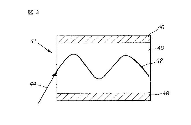
表1のデータから明らかなように、AQ 55中のLaponite Sの質量割合が増加するにつれて、層の全体的な屈折率が低減される。このことは、水分散性ポリエステルマトリックスの屈折率を減少させる上での本発明の層状粒子の有効性を示している。延伸ポリエチレンテレフタレートシートは、典型的には、延伸度に応じて1.6を上回る屈折率を得るので、試料の層(2〜11)のいずれかを、延伸ポリエチレンテレフタレートコアのための、屈折率が低減された効果的なクラッド層として使用することができる。 デ ー タ As evident from the data in Table 1, as the mass percentage of Laponite S in AQ55 increases, the overall refractive index of the layer decreases. This demonstrates the effectiveness of the layered particles of the present invention in reducing the refractive index of a water-dispersible polyester matrix. Stretched polyethylene terephthalate sheets typically have a refractive index of greater than 1.6 depending on the degree of stretching, so that any of the sample layers (2-11) may have a refractive index for the stretched polyethylene terephthalate core. Can be used as an effective cladding layer with reduced.
いかなるバインダーポリマーも使用せずにLaponite S及びLaponite RDSの屈折率データを表2において比較する。なお、Laponite Sがフッ素化されたものであることを除けば、Laponite S及びLaponite RDSの組成は極めて類似している。 屈折 Compare the refractive index data of Laponite S and Laponite RDS in Table 2 without using any binder polymer. The compositions of Laponite S and Laponite RDS are very similar except that Laponite S is fluorinated.
Laponite SがLaponite RDSよりも屈折率が低いことは明らかであり、このことは、本発明の実施するのにフッ素化スメクタイトの使用が望ましいことを実証している。 It is clear that Laponite S has a lower refractive index than Laponite RDS, demonstrating the desirability of using fluorinated smectite to practice the present invention.
導波路要素の例
本発明の導波路要素を下記のように構成することができる:
Examples of Waveguide Elements The waveguide elements of the present invention can be configured as follows:
導波路要素のコアは、約120μm厚のポリエステルフィルムベース(L5)を含み、屈折率を1.56に調整するように、このL5にはポリテトラフルオロエチレンが添加されている。このポリエステルフィルムL5は、実質的にクリアな3層のクラッド層をそのポリエステルフィルムのそれぞれの側に有している(上側にはL4、L3、L2、及び下側にはL6、L7及びL8)。ポリエステルフィルムベースの同じ側のクラッド層のそれぞれにおける層状粘土粒子の濃度は異なり、増加している。層状粒子としてLaponite Sを含み、またバインダーポリマーとしてAQ55を含むL2,3,4,6,7及び8のそれぞれの層を、約1μm厚(乾燥)でコートする。3層スライドホッパーを使用して水性コーティング組成物からコーティングを形成する。このスライドホッパーにおいて、L2,3及び4の全ての層を同時にコートし、そして完全に乾燥させる。クラッド層L2,3及び4中のLaponite S:AQ55の質量比をそれぞれ20:80、10:90及び5:95で維持する。層を乾燥させるときには、層間の粒子を強制的に僅かに移行させることにより層間の勾配効果が生じるように、空気衝撃力を調整する。この例では、L2,3及び4をポリエステルフィルム上にコートし、そして乾燥させ、次いでL6,7及び8を反対側で同様にコートし、そして乾燥させる。第3のコーティングパスにおいて、カーボンブラックの微細分散体とコポリエステル樹脂とを含む約2μmの厚(乾燥)の黒色接着剤層(L1及びL9)をそれぞれの側にコートし、そして乾燥させる。 コ ア The core of the waveguide element includes a polyester film base (L5) having a thickness of about 120 μm, to which polytetrafluoroethylene is added so as to adjust the refractive index to 1.56. This polyester film L5 has three substantially clear cladding layers on each side of the polyester film (L4, L3, L2 on the top and L6, L7 and L8 on the bottom). . The concentration of layered clay particles in each of the cladding layers on the same side of the polyester film base is different and increasing. Each layer of L2, 3, 4, 6, 7 and 8 containing Laponite S as layered particles and AQ55 as binder polymer is coated to a thickness of about 1 μm (dry). A coating is formed from the aqueous coating composition using a three-layer slide hopper. In this slide hopper, all layers of L2, 3 and 4 are coated simultaneously and dried completely. The mass ratio of Laponite S: AQ55 in the cladding layers L2, 3 and 4 is maintained at 20:80, 10:90 and 5:95, respectively. When drying the layers, the air impact force is adjusted so that a gradient effect between the layers is created by forcing the particles between the layers to migrate slightly. In this example, L2, 3 and 4 are coated on a polyester film and dried, then L6, 7 and 8 are similarly coated on the other side and dried. In a third coating pass, about 2 μm thick (dry) black adhesive layers (L1 and L9) containing a fine dispersion of carbon black and a copolyester resin are coated on each side and dried.
上述のような導波路構造のコーティング後、これにスリットを入れ、そしてこれを切断して幅250ミル×長さ10000ミルの細いストリップを形成する。これらのストリップを6000ミルの高さに互いに上下に積み重ね、約0.07MPaの圧力でこの積層体をクランプし、この積層体を高温炉(90℃)内に10時間置く。これにより、接着剤層が融合してフラットな平面状導波路を形成することが可能になる。 After coating the waveguide structure as described above, slit it and cut it to form a thin strip 250 mils wide x 10,000 mils long. The strips are stacked one on top of the other at a height of 6000 mils, the stack is clamped at a pressure of about 0.07 MPa, and the stack is placed in a high temperature furnace (90 ° C.) for 10 hours. Thereby, the adhesive layer can be fused to form a flat planar waveguide.
ポリエステル及びポリテトラフルオロエチレンのコアの屈折率は1.56であり、コートした層の屈折率は、ポリエステル層に隣接した側からポリエステルコアから最も離れた側に向かって濃度が増加するのに伴い、約1.56(ポリエステル層に隣接した側)から1.53(ポリエステルコアから最も離れた側)への勾配を形成した。 The refractive index of the polyester and polytetrafluoroethylene cores is 1.56, and the refractive index of the coated layer increases with increasing concentration from the side adjacent to the polyester layer to the side furthest away from the polyester core. , From about 1.56 (side adjacent to the polyester layer) to 1.53 (side furthest from the polyester core).
本発明の実施態様には:
前記中心コアが80〜100%の透過率を有し;
前記光透過性ポリマーが、水溶性ポリマー、親水性コロイド、及び水不溶性ポリマーから成る群から選択された少なくとも1種の材料を含み、そして熱硬化性ポリマー、例えばポリエステル、酢酸セルロース、ポリカーボネート、ポリメチルメタクリレート、環状オレフィン及びこれらのコポリマーであってよい実施態様を含む。
Embodiments of the present invention include:
Said central core has a transmittance of 80-100%;
The light-transmitting polymer includes at least one material selected from the group consisting of a water-soluble polymer, a hydrophilic colloid, and a water-insoluble polymer, and a thermosetting polymer such as polyester, cellulose acetate, polycarbonate, and polymethyl. Includes embodiments that may be methacrylates, cyclic olefins and copolymers thereof.
本発明は、光学要素において:
前記クラッド層が吸光性であって、望ましくは黒色であり;
前記クラッド層がさらに接着剤を含み;
前記中心コアがアーチ形、例えばファイバーであるか、又は、少なくとも1層の環状クラッド層によって取り囲まれた円筒状体であるか、或いは、前記中心コアが凸状又は凹状のレンズのように形作られており、前記中心コアは複数のレンズ又はレンズアレイを有することができ、前記レンズアレイは所定の幾何学的形状を有することができ;
前記層状粒子が、前記光チャネルの長手方向に対して垂直な平面内で、前記光チャネルの中心から離れるにつれて濃度が増加する濃度勾配を生じ;
前記層状粒子の最大粒子寸法対最小粒子寸法のアスペクト比が10:1〜1000:1であり、そして
前記粒子が、ヒドロタルサイト、フィロシリケート、例えばスメクタイト、特にモンモリロナイト(ケイ酸アルミニウムを含むモンモリロナイトを包含)、又は、望ましくはフッ素化され、好適にはケイ酸マグネシウムを含有するヘクトライトを含むスメクタイトを含む実施態様を含む。
The invention relates to an optical element:
Said cladding layer is light absorbing, preferably black;
The cladding layer further comprises an adhesive;
The central core is arched, for example a fiber, or a cylindrical body surrounded by at least one annular cladding layer, or the central core is shaped like a convex or concave lens The central core may have a plurality of lenses or lens arrays, and the lens arrays may have a predetermined geometric shape;
The layered particles create a concentration gradient in a plane perpendicular to the longitudinal direction of the light channel, the concentration increasing with distance from the center of the light channel;
The layered particles have an aspect ratio of maximum particle size to minimum particle size of 10: 1 to 1000: 1, and the particles are composed of hydrotalcite, phyllosilicate such as smectite, especially montmorillonite (montmorillonite including aluminum silicate. Or embodiments including smectites, including hectorite, preferably containing fluorinated and preferably magnesium silicate.
スメクタイトが合成のものであるか、有機変性されたものであるか、又はフッ素化されたものである粒子も有用である。 Particles in which the smectite is synthetic, organically modified, or fluorinated are also useful.
有用なのは、前記高分子チャネルの厚さが0.5〜1000μmである要素であって、1段当たり0.01未満の屈折率変化を有する一連の階段状変化によって勾配が形成されている要素である。
本明細書中に引用した特許明細書及びその他の刊行物の内容全体は、引用により、本明細書中に含まれていることにする。
Useful are elements in which the thickness of the polymer channel is between 0.5 and 1000 μm, where the gradient is formed by a series of step changes having a refractive index change of less than 0.01 per step. is there.
The entire contents of patent specifications and other publications cited herein are hereby incorporated by reference.
11…光チャネル
12…上側クラッド層
14…光透過性コア
16…下側クラッド層
21…二重クラッド導波路
20…上側クラッドキャップ層
22…上側クラッド層
24…光透過性コア
26…下側クラッド層
28…下側クラッドキャップ層
30…光線
40…光透過性コア
41…勾配屈折率導波路
42…光線
44…空気又は他の媒体から導波路に入射する光線
46…上側クラッド層
48…下側クラッド層
11
Claims (11)
Applications Claiming Priority (1)
| Application Number | Priority Date | Filing Date | Title |
|---|---|---|---|
| US10/269,628 US6728456B1 (en) | 2002-10-11 | 2002-10-11 | Waveguide with nanoparticle induced refractive index gradient |
Publications (1)
| Publication Number | Publication Date |
|---|---|
| JP2004133473A true JP2004133473A (en) | 2004-04-30 |
Family
ID=32030391
Family Applications (1)
| Application Number | Title | Priority Date | Filing Date |
|---|---|---|---|
| JP2003353955A Pending JP2004133473A (en) | 2002-10-11 | 2003-10-14 | Waveguide having refractive index gradient induced by nanoparticle |
Country Status (3)
| Country | Link |
|---|---|
| US (1) | US6728456B1 (en) |
| EP (1) | EP1408352A3 (en) |
| JP (1) | JP2004133473A (en) |
Families Citing this family (23)
| Publication number | Priority date | Publication date | Assignee | Title |
|---|---|---|---|---|
| JP2002199455A (en) * | 2000-12-27 | 2002-07-12 | Matsushita Electric Ind Co Ltd | Cordless phone |
| US6832037B2 (en) * | 2002-08-09 | 2004-12-14 | Eastman Kodak Company | Waveguide and method of making same |
| US20040067033A1 (en) * | 2002-10-07 | 2004-04-08 | Eastman Kodak Company | Waveguide with nanoparticle induced refractive index gradient |
| US7094461B2 (en) * | 2002-12-31 | 2006-08-22 | 3M Innovative Properties Company | P-polarizer with large z-axis refractive index difference |
| JP4261376B2 (en) * | 2004-01-28 | 2009-04-30 | 富士フイルム株式会社 | Sheet-like light guide and communication system using the same |
| US20060163160A1 (en) * | 2005-01-25 | 2006-07-27 | Weiner Michael L | Halloysite microtubule processes, structures, and compositions |
| US7425232B2 (en) * | 2004-04-05 | 2008-09-16 | Naturalnano Research, Inc. | Hydrogen storage apparatus comprised of halloysite |
| US20060076354A1 (en) * | 2004-10-07 | 2006-04-13 | Lanzafame John F | Hydrogen storage apparatus |
| DE102004061324A1 (en) * | 2004-12-20 | 2006-06-22 | Epg (Engineered Nanoproducts Germany)Gmbh | Optical component of an inorganic-organic hybrid material for the production of refractive index gradient layers with rapid kinetics and process for their preparation |
| DE102004061323A1 (en) * | 2004-12-20 | 2006-06-22 | Epg (Engineered Nanoproducts Germany)Gmbh | Optical component of an inorganic-organic hybrid material for the production of refractive index gradient layers with high lateral resolution and method for their preparation |
| US7823214B2 (en) | 2005-01-07 | 2010-10-26 | Apple Inc. | Accessory authentication for electronic devices |
| US7400490B2 (en) * | 2005-01-25 | 2008-07-15 | Naturalnano Research, Inc. | Ultracapacitors comprised of mineral microtubules |
| EP2079663A1 (en) * | 2006-10-11 | 2009-07-22 | Universidad De Chile | Hybrid clays for obtaining nanocomposites and the preparation process of these clays and polyolefin / clay nanocomposites |
| US20080305255A1 (en) * | 2007-06-07 | 2008-12-11 | Fujifilm Manufacturing U.S.A. Inc. | Optical waveguide coating |
| US7496263B2 (en) * | 2007-06-07 | 2009-02-24 | Fujifilm Manfacturing U.S.A. Inc. | Thermosetting optical waveguide coating |
| WO2010019612A2 (en) | 2008-08-11 | 2010-02-18 | Greenhill Antiballistics Corporation | Densely packed particle structure |
| US8411375B2 (en) * | 2008-01-25 | 2013-04-02 | Aptina Imaging Corporation | Method and apparatus providing gradient index of refraction lens for image sensors |
| US8847915B2 (en) * | 2008-11-26 | 2014-09-30 | Avago Technologies General Ip (Singapore) Pte. Ltd. | Light pipe array lens, optical finger navigation device with the lens and method for making the device |
| CA2814986C (en) | 2010-10-18 | 2019-01-15 | Greenhill Antiballistics Corporation | Gradient nanoparticle-carbon allotrope-polymer composite material |
| FR2980279B1 (en) | 2011-09-20 | 2013-10-11 | Soitec Silicon On Insulator | METHOD FOR MANUFACTURING A COMPOSITE STRUCTURE TO BE SEPARATED BY EXFOLIATION |
| WO2015130261A1 (en) * | 2014-02-25 | 2015-09-03 | Empire Technology Development Llc | Silicon chip with refractive index gradient for optical communication |
| US9507182B2 (en) * | 2014-06-02 | 2016-11-29 | Vadient Optics. LLC. | Nanocomposite electro-optic modulator |
| US11465375B2 (en) * | 2015-12-15 | 2022-10-11 | Vadient Optics, Llc | Nanocomposite refractive index gradient variable focus optic |
Citations (4)
| Publication number | Priority date | Publication date | Assignee | Title |
|---|---|---|---|---|
| JPH02109002A (en) * | 1988-10-19 | 1990-04-20 | Mitsubishi Rayon Co Ltd | Optical transmitting body and its production |
| JP2000508783A (en) * | 1996-04-04 | 2000-07-11 | インスティトゥート フィア ノイエ マテリアーリエン ゲマインニュッツィゲ ゲゼルシャフト ミット ベシュレンクタ ハフトゥンク | Optical component having gradient structure and method for manufacturing the component |
| JP2001106834A (en) * | 1999-07-30 | 2001-04-17 | Sumitomo Chem Co Ltd | Olefin resin composition and molded product using the same |
| WO2001077732A1 (en) * | 2000-04-05 | 2001-10-18 | Brookhaven Science Associates | Planar optical waveguides for optical panel having gradient refractive index core |
Family Cites Families (8)
| Publication number | Priority date | Publication date | Assignee | Title |
|---|---|---|---|---|
| US4739007A (en) * | 1985-09-30 | 1988-04-19 | Kabushiki Kaisha Toyota Chou Kenkyusho | Composite material and process for manufacturing same |
| AU6424296A (en) * | 1995-08-29 | 1997-03-06 | Sumitomo Chemical Company, Limited | Gas barrier resin composition and process for producing the same |
| US6200503B1 (en) * | 1996-09-13 | 2001-03-13 | Mohammad W. Katoot | Graded index polymer optical fibers and process for manufacture thereof |
| US6086999A (en) * | 1997-06-12 | 2000-07-11 | Boston Optical Fiber, Inc. | Method for producing a graded index plastic optical material |
| US6034163A (en) * | 1997-12-22 | 2000-03-07 | Eastman Chemical Company | Polyester nanocomposites for high barrier applications |
| US6002826A (en) * | 1998-08-28 | 1999-12-14 | Brookhaven Science Associates | Thin display optical projector |
| US6301417B1 (en) * | 1998-08-31 | 2001-10-09 | Brookhaven Science Associates | Ultrathin optical panel and a method of making an ultrathin optical panel |
| FR2784196B1 (en) * | 1998-10-01 | 2000-12-15 | Cit Alcatel | INDEX GRADIENT PLASTIC OPTICAL FIBER AND CONTINUOUSLY MANUFACTURING INDEX GRADIENT PLASTIC OPTICAL FIBER |
-
2002
- 2002-10-11 US US10/269,628 patent/US6728456B1/en not_active Expired - Fee Related
-
2003
- 2003-09-29 EP EP03078089A patent/EP1408352A3/en not_active Withdrawn
- 2003-10-14 JP JP2003353955A patent/JP2004133473A/en active Pending
Patent Citations (5)
| Publication number | Priority date | Publication date | Assignee | Title |
|---|---|---|---|---|
| JPH02109002A (en) * | 1988-10-19 | 1990-04-20 | Mitsubishi Rayon Co Ltd | Optical transmitting body and its production |
| JP2000508783A (en) * | 1996-04-04 | 2000-07-11 | インスティトゥート フィア ノイエ マテリアーリエン ゲマインニュッツィゲ ゲゼルシャフト ミット ベシュレンクタ ハフトゥンク | Optical component having gradient structure and method for manufacturing the component |
| JP2001106834A (en) * | 1999-07-30 | 2001-04-17 | Sumitomo Chem Co Ltd | Olefin resin composition and molded product using the same |
| WO2001077732A1 (en) * | 2000-04-05 | 2001-10-18 | Brookhaven Science Associates | Planar optical waveguides for optical panel having gradient refractive index core |
| JP2003530590A (en) * | 2000-04-05 | 2003-10-14 | ブルックヘイブン サイエンス アソシエイツ | Planar optical waveguide for optical panel with gradient index core |
Also Published As
| Publication number | Publication date |
|---|---|
| US6728456B1 (en) | 2004-04-27 |
| US20040071422A1 (en) | 2004-04-15 |
| EP1408352A2 (en) | 2004-04-14 |
| EP1408352A3 (en) | 2004-07-28 |
Similar Documents
| Publication | Publication Date | Title |
|---|---|---|
| US6832037B2 (en) | Waveguide and method of making same | |
| JP2004133473A (en) | Waveguide having refractive index gradient induced by nanoparticle | |
| KR102594424B1 (en) | Optical sheet, polarizer, optical sheet sorting method and optical sheet manufacturing method, and display device | |
| TW567338B (en) | Antireflection film, polarizing plate, and apparatus for displaying an image | |
| JP5330539B2 (en) | High refractive index inorganic oxide nanoparticles containing a surface treatment agent, polymerizable resin composition, and article | |
| JP5049542B2 (en) | Antireflection film, polarizing plate, and image display device using the same | |
| US8530572B2 (en) | Brightness enhancing film comprising nanocomposite structure having improved crack resistance | |
| CN1322338C (en) | Antireflection film, polarizing plate and image display device | |
| US7691459B2 (en) | Inorganic fine particle-containing composition, optical film, antireflection film and polarizing film, and polarizing plate and display device using the same | |
| TWI454753B (en) | Optical laminate, polarizing plate, display device, and method for making an optical laminate | |
| US6844047B2 (en) | Optical element containing nanocomposite materials | |
| JP2010277059A (en) | Antireflection film and polarizing plate including the same | |
| JP2007233389A (en) | Optical substrate comprising boron nitride particle | |
| WO2006106756A1 (en) | Optical layered product | |
| US20040067033A1 (en) | Waveguide with nanoparticle induced refractive index gradient | |
| JP2007069471A (en) | Optical film, antireflection film, polarizing plate, and display | |
| JP2006299248A (en) | Composition comprising inorganic fine particles, optical film, antireflection film, and polarizing plate and display device using the same | |
| JP2009251190A (en) | Optical film, polarizing plate and image display apparatus | |
| JP2007164151A (en) | Optical film, antireflection film, polarizing plate, and image display device | |
| CN100472232C (en) | Antireflection film, polarizing plate and image display device | |
| JP7380960B1 (en) | Optical films, image display panels and image display devices | |
| WO2023163185A1 (en) | Optical member and ar glasses and head-mounted display using said optical member | |
| WO2023210622A1 (en) | Optical film, image display panel, and image display device | |
| JP2007171365A (en) | Reflective polarizing film, method of manufacturing reflective polarizing film, and liquid crystal display device | |
| JP2007057873A (en) | Method of manufacturing grid polarization film, grid polarization film, polarizing element and liquid crystal display device |
Legal Events
| Date | Code | Title | Description |
|---|---|---|---|
| A621 | Written request for application examination |
Free format text: JAPANESE INTERMEDIATE CODE: A621 Effective date: 20060803 |
|
| A711 | Notification of change in applicant |
Free format text: JAPANESE INTERMEDIATE CODE: A711 Effective date: 20080205 |
|
| A977 | Report on retrieval |
Free format text: JAPANESE INTERMEDIATE CODE: A971007 Effective date: 20091001 |
|
| A131 | Notification of reasons for refusal |
Free format text: JAPANESE INTERMEDIATE CODE: A131 Effective date: 20091006 |
|
| A601 | Written request for extension of time |
Free format text: JAPANESE INTERMEDIATE CODE: A601 Effective date: 20091228 |
|
| A602 | Written permission of extension of time |
Free format text: JAPANESE INTERMEDIATE CODE: A602 Effective date: 20100106 |
|
| A02 | Decision of refusal |
Free format text: JAPANESE INTERMEDIATE CODE: A02 Effective date: 20100629 |