JP2004129054A - Pathway controller and method for generating pathway control information - Google Patents
Pathway controller and method for generating pathway control information Download PDFInfo
- Publication number
- JP2004129054A JP2004129054A JP2002292504A JP2002292504A JP2004129054A JP 2004129054 A JP2004129054 A JP 2004129054A JP 2002292504 A JP2002292504 A JP 2002292504A JP 2002292504 A JP2002292504 A JP 2002292504A JP 2004129054 A JP2004129054 A JP 2004129054A
- Authority
- JP
- Japan
- Prior art keywords
- information
- transfer
- control information
- route
- pathway
- Prior art date
- Legal status (The legal status is an assumption and is not a legal conclusion. Google has not performed a legal analysis and makes no representation as to the accuracy of the status listed.)
- Pending
Links
Images


Classifications
-
- H—ELECTRICITY
- H04—ELECTRIC COMMUNICATION TECHNIQUE
- H04L—TRANSMISSION OF DIGITAL INFORMATION, e.g. TELEGRAPHIC COMMUNICATION
- H04L41/00—Arrangements for maintenance, administration or management of data switching networks, e.g. of packet switching networks
- H04L41/12—Discovery or management of network topologies
-
- H—ELECTRICITY
- H04—ELECTRIC COMMUNICATION TECHNIQUE
- H04L—TRANSMISSION OF DIGITAL INFORMATION, e.g. TELEGRAPHIC COMMUNICATION
- H04L45/00—Routing or path finding of packets in data switching networks
- H04L45/02—Topology update or discovery
-
- H—ELECTRICITY
- H04—ELECTRIC COMMUNICATION TECHNIQUE
- H04L—TRANSMISSION OF DIGITAL INFORMATION, e.g. TELEGRAPHIC COMMUNICATION
- H04L45/00—Routing or path finding of packets in data switching networks
- H04L45/42—Centralised routing
Abstract
Description
【0001】
【発明の属する技術分野】
本発明は、経路制御装置及び経路制御情報生成方法に関する。
【0002】
【従来の技術】
従来におけるインターネットは、経路制御機能及び転送制御機能をネットワーク内の各転送装置が有し、転送装置は独自の経路制御情報に基づいてパケットの転送を行っていた。転送装置が有する経路制御情報は、ネットワーク管理者レベルの協定により転送装置同士がパケットを交換するか否かを決定することもできるが、基本的には転送装置同士で情報を交換するか、それぞれの転送装置が経路を計算することにより確立されるので、転送装置以外は経路情報すべてを把握することはできない。また、転送装置同士は、同じプロトコルを理解する転送装置同士のみが同じメカニズムを用いて経路制御情報を構築するため、異なるプロトコルを有する転送装置同士では交換した経路情報が利用できないため、互換性がない。(例えば、特許文献1、非特許文献1及び2参照。)
【0003】
【特許文献1】
特開2000−209264号公報
【非特許文献1】
Mark Miller, Implementing IPv6 second edition, 2000 pp.193−220
【非特許文献2】
C. Hedrick, Routing Information protocol (RFC 1058), June 1988
【0004】
【発明が解決しようとする課題】
しかしながら、経路制御機能及び転送制御機能をネットワーク内の各転送装置が有していたのでは、経路制御機能の拡張又は削除が難しく、また、ネットワーク内に異なる経路制御機能が混在することでネットワークの制御が複雑となってしまう。特に、経路制御に関しては、プロトコルによって転送装置が収集したり計算したりする方法が異なるため、同じプロトコルを有さない転送装置とは適切な情報交換が行えない。また、経路情報を生成する際に、プロトコルによっては、計算方法がとても複雑なため、転送装置の機能が複雑化するという問題がある。
【0005】
本発明は、上述の点に鑑みてなされたもので、接続される転送装置の機能を単純化及び高速化することが可能となると共に、経路情報を適切に把握することが可能な経路制御装置及び経路制御情報生成方法を提供することを課題とする。
【0006】
【課題を解決するための手段】
本発明に係る経路制御装置は、転送制御処理を行う転送装置が接続された経路制御装置であって、転送装置から通知される経路情報に基づいて経路制御情報を一括して生成する経路制御情報生成手段を有することを特徴としている。
【0007】
本発明に係る経路制御装置では、経路制御情報生成手段により、転送装置から通知される経路情報に基づいて経路制御情報が一括して生成されることとなる。このように、経路制御装置が上記経路制御情報生成手段を有して、一括して一定の方式に従って経路制御情報を生成することで、転送装置に経路制御情報を生成するための複雑な計算・能力を持たせる必要がなくなり、当該経路制御装置に接続される転送装置の機能を単純化及び高速化することができる。また、転送装置に関して総体的な一貫性のある経路制御情報が生成されることとなり、送られるパケットが通過する経路を容易に把握することができる。
【0008】
また、経路制御情報生成手段は、経路制御情報として経路制御テーブルを作成することが好ましい。
【0009】
また、経路制御情報生成手段は、物理的に接続されて経路情報を通知した全ての転送装置に対して、経路制御情報を生成することが好ましい。このように構成した場合は、経路制御装置がネットワーク全体の状況を把握した上で、当該状況を反映した経路制御情報を生成し易くなる。
【0010】
また、経路情報は、少なくとも転送装置間の隣接情報と、転送装置同士を接続するリンクのメトリック情報とを含み、経路制御情報生成手段は、少なくともネットワークにおけるトポロジー情報が変更された際に、変更された情報に基づいて新たに経路制御情報を生成することが好ましい。このように構成した場合は、ネットワークの状況に応じて適切に経路制御情報を生成することができる。
【0011】
また、経路制御情報生成手段は、転送装置間においてメトリックが最小値となる転送経路が複数存在する場合、当該複数の転送経路全ての経路情報を把握していることが好ましい。このように構成した場合は、経路制御装置が、メトリックが最小値となる全ての転送経路の状況を把握した上で、当該状況を反映した経路制御情報を適切に生成することができる。
【0012】
本発明に係る経路制御情報生成方法は、転送制御処理を行う転送装置が接続された経路制御装置における経路制御情報生成方法であって、経路制御情報生成手段が、転送装置から通知される経路情報に基づいて当該転送装置の数を認識し、数を認識した転送装置に対して初期の経路制御テーブルを作成した後に、転送装置毎に、他の全ての転送装置までのメトリックを計算して、メトリックが最小値となる全ての経路において、当該最小値と隣接する転送装置の識別子とを用いて経路制御テーブルを作成することを特徴としている。
【0013】
本発明に係る経路制御情報生成方法では、経路制御情報生成手段により、転送装置から通知される経路情報に基づいて当該転送装置の数が認識され、数を認識した転送装置に対して初期の経路制御テーブルが作成された後に、転送装置毎に、他の全ての転送装置までのメトリックが計算されて、メトリックが最小値となる全ての経路において、当該最小値と隣接する転送装置の識別子とを用いて経路制御テーブルが作成されることとなる。これにより、経路制御テーブルを適切に作成することができる。
【0014】
【発明の実施の形態】
本発明の実施形態に係る経路制御装置及び経路制御情報生成方法について図面を参照して説明する。なお、説明において、同一要素又は同一機能を有する要素には、同一符号を用いることとし、重複する説明は省略する。
【0015】
図1は、本実施形態に係る通信システムの構成を示す概略図である。通信システム1は、図1に示されるように、複数の転送装置R1〜R6と、経路制御装置10とを含んでいる。
【0016】
各転送装置R1〜R6は、転送制御処理を行うことでパケットを転送すると共に、隣接する転送装置間において隣接情報を交換している。各転送装置R1〜R6は、物理的には、ルータ等により構成することができる。本実施形態においては、例えば、転送装置R1は転送装置R2との間で隣接情報を交換し、転送装置R2は更に転送装置R3,R5,R6との間で隣接情報を交換している。また、転送装置R3は転送装置R2,R5との間で隣接情報を交換し、転送装置R4は転送装置R5との間で隣接情報を交換し、転送装置R5は転送装置R2,R3,R4との間で隣接情報を交換し、転送装置R6は転送装置R2との間で隣接情報を交換している。
【0017】
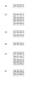
すなわち、各転送装置R1〜R6は、図2に示されるように、物理的に接続されている周囲の転送装置に対して、隣接情報として、自らの識別子情報、サブネット情報及びメトリック情報等を通知する。また、各転送装置R1〜R6は、周囲の転送装置から通知された隣接情報(識別子情報、サブネット情報及びメトリック情報等)を受領することで、接続情報やネットワークの輻輳情報を知る。図2において、例えば、「R1:M1−2」は、転送装置R1から転送装置R2に送られる隣接情報であり、「R1」は転送装置R1の識別子情報であり、「M1−2」は転送装置R1から転送装置R2へのメトリック情報である。また、「R2:M2−1」は、転送装置R2から転送装置R1に送られる隣接情報であり、「R2」は転送装置R2の識別子情報であり、「M2−1」は転送装置R2から転送装置R1へのメトリック情報である。同様に、「R2:M2−3」は、転送装置R2から転送装置R3に送られる隣接情報であり、「R2」は転送装置R2の識別子情報であり、「M2−3」は転送装置R2から転送装置R3へのメトリック情報である。また、「R3:M3−2」は、転送装置R3から転送装置R2に送られる隣接情報であり、「R3」は転送装置R3の識別子情報であり、「M3−2」は転送装置R3から転送装置R2へのメトリック情報である。
【0018】
上述した隣接情報の交換は定期的に行われており、これにより、各転送装置R1〜R6は、トポロジーの変化を感知することとができる。また、例えば自らが有するバッファーの利用状況を見ることで輻輳を感知する。これらを基にして、各転送装置R1〜R6は、図3(a)〜(f)に示されるような、トポロジー情報を作成する。図3(a)は、転送装置R1が作成したトポロジー情報を示し、図3(b)は、転送装置R2が作成したトポロジー情報を示し、図3(c)は、転送装置R3が作成したトポロジー情報を示し、図3(d)は、転送装置R4が作成したトポロジー情報を示し、図3(e)は、転送装置R5が作成したトポロジー情報を示し、図3(f)は、転送装置R6が作成したトポロジー情報を示している。例えば、転送装置R1が作成したトポロジー情報は、当該転送装置R1が物理的に接続されている転送装置R2との間の情報交換に基づいて作成され、図3(a)に示されるように、「R1−R2:M1−2」をトポロジー情報として作成する。ここで、「R1−R2」は転送装置R1から転送装置R2までのリンク情報(隣接情報)であり、「M1−2」は転送装置R1から転送装置R2までのリンクにおけるメトリック情報である。
【0019】
また、各転送装置R1〜R6は、経路制御装置10と物理的に接続されており、図4に示されるように、自らが有するトポロジー情報(リンク情報及びメトリック情報)を経路制御装置10に送信する。また、各転送装置R1〜R6は、輻輳情報といった動的な情報も、経路制御装置10に送信する。各転送装置R1〜R6から経路制御装置10への情報通知は、初期化の際と、ネットワークに変化があった際にのみ行うことができる。
【0020】
経路制御装置10は、上述したように各転送装置R1〜R6と物理的に接続されており、経路制御情報生成手段としての経路制御情報生成部11を有している。この経路制御情報生成部11は、各転送装置R1〜R6から通知されるトポロジー情報等の経路情報に基づいて経路制御情報を一括して生成する。経路制御情報生成部11は、接続されて経路情報を通知した全ての転送装置に対して、経路制御情報として、経路制御テーブルTを作成する。
【0021】
また、経路制御装置10は、経路制御情報生成部11にて生成した経路制御テーブルTに含まれる経路制御情報を各転送装置R1〜R6に送信する。各転送装置R1〜R6に送信される経路制御情報は、当該転送装置R1〜R6におけるパケットの送受信に関連する部分となる。情報が送信された各転送装置R1〜R6は、自らが有するキャッシュ等の記憶手段に当該経路制御情報を格納し、当該経路制御情報に基づいて、パケットの送受信を制御する。
【0022】
続いて、図5に基づいて、経路制御情報生成部11における経路制御テーブルTの作成処理について説明する。
【0023】
まず、経路制御情報生成部11は、経路情報を通知したN個(本実施形態においては、6個)の転送装置R1〜R6からトポロジー情報の通知があると(S101)、各転送装置R1〜R6から初期化後に通知されるトポロジー情報を基にして、図6に示される経路制御テーブルT[a][b]を作成する(S103)。図6に示された経路制御テーブルT[a][b]は、送信側の転送装置(図6中、「S」)と受信側の送信装置(図6中、「D」)との間のメトリック情報を記した初期経路テーブルである。例えば、送信側(S)の転送装置R1と受信側(D)の送信装置R2との間のメトリック情報として、送信側の転送装置R1と受信側の転送装置R2とで規定されるエントリーに、「M1−2」が記されている。転送装置R1と送信装置R3〜R6との間には、現状においては、物理的な接続が確立されておらず、受信側(D)の送信装置R3〜R6とで規定されるエントリーには情報が記されていない。
【0024】
次に、「i」を「1」とし(S105)、「i」が「N」以下であるか否かを判定する(S107)。「i」が「N」より大きい場合には、処理を終える。ここで、「i」は、送信側の転送装置を特定するための記号である。一方、「i」が「N」以下である場合には、「j」を「1」とする(S109)。ここで、「j」は、受信側の転送装置を特定するための記号である。
【0025】
続いて、送信側の転送装置「i」から、最初にパケットを送る転送装置「k」を介して受信側の転送装置「j」までの経路のメトリックを計算し、最小値を有する経路において、その最小値と最初にパケットを転送する隣接する転送装置識別子を用いて、経路制御テーブルを作成する(S111)。また、最小値を有する経路が複数存在する場合もあるので、上記「k」とは異なる「m」となる転送装置を介した受信側の転送装置「j」までの経路のメトリックを計算し、最小値を有する経路において、その最小値と最初にパケットを転送する隣接する転送装置識別子を用いて、経路制御テーブルを作成する(S113)。
【0026】
そして、「j」が「N」以下であるか否かを判定し(S115)、「j」が「N」以下である場合には、「j」を「j+1」として(S117)、上記S111に戻る。一方、「j」が「N」より大きい場合には、全てのT[i][j]に対して値が存在するか否か、すなわち経路情報を通知したN個の転送装置R1〜R6間におけるメトリックの最小値と最初にパケットを転送する隣接する転送装置識別子が決まったか否かを判定する(S119)。全てのT[i][j]に対して値が存在しない場合には、上記S109に戻る。一方、全てのT[i][j]に対して値が存在する場合には、「i」を「i+1」として(S121)、上記S107に戻る。
【0027】
なお、経路制御テーブルを計算する際に用いるデータ構造は、
Typedef struct cost[int value; int router; cost* next;] Cost;Cost T[i][j];
にて表され、各エントリーとして、メトリックの値、隣接転送装置の識別子、次エントリーへのポインターを有し、当該エントリーを配列として定義される。なお、各エントリーの配列がテーブルとなり、当該テーブルの構造を図7に示す。
【0028】
上記作成処理により、図8に示される経路制御テーブルTが作成されることとなる。例えば、送信側の転送装置R1と受信側の転送装置R3とは、物理的に直接接続されている訳ではないが、転送装置R2を介することで、送信側の転送装置R1と受信側の転送装置R3とが接続可能となる。このため、最初にパケットを送る転送装置は「R2(k=2)」となり、送信側の転送装置R1と受信側の転送装置R3との間のメトリックは、転送装置R1と転送装置R2との間のメトリック「M1−2」と転送装置R2と転送装置R3との間のメトリック「M2−3」との和となる。したがって、図8に示されるように、送信側の転送装置R1と受信側の転送装置R3とで規定されるエントリーに、転送装置R1から転送装置R3までの総メトリックとして「M1−2+M2−3」が記され、最初の転送装置として「R2」が記されることとなる。
【0029】
また、送信側の転送装置R3と受信側の転送装置R6との間については、最初にパケットを送信する転送装置が転送装置R2と転送装置R5の2個存在することから、図8に示されるように、送信側の転送装置R3と受信側の転送装置R6とで規定されるエントリーに、転送装置R2を介した場合と、転送装置R5を介した場合の2通りの情報が記載されている。
【0030】
そして、経路制御装置10は、図9に示されるように、作成した経路制御テーブルTに含まれる情報を各転送装置R1〜R6に送信する。例えば、転送装置R1には、経路制御テーブルTのうち、当該転送装置R1を送信側の転送装置とした図8における送信側「R1」の行の情報T[R1][]が経路制御情報として送信される。同様に、転送装置R2には、当該転送装置R2を送信側の転送装置とした図8における送信側「R2」の行の情報T[R2][]が経路制御情報として送信され、転送装置R3には、当該転送装置R3を送信側の転送装置とした図8における送信側「R3」の行の情報T[R3][]が経路制御情報として送信され、転送装置R4には、当該転送装置R4を送信側の転送装置とした図8における送信側「R4」の行の情報T[R4][]が経路制御情報として送信される。また、転送装置R5には、当該転送装置R5を送信側の転送装置とした図8における送信側「R5」の行の情報T[R5][]が経路制御情報として送信され、転送装置R6には、当該転送装置R6を送信側の転送装置とした図8における送信側「R6」の行の情報T[R6][]が経路制御情報として送信される。
【0031】
以上のように、本実施形態の経路制御装置10では、経路制御処理と転送制御処理とが分離されて、経路制御処理が経路制御装置10にて実行され、転送制御処理が各転送装置R1〜R6にて実行されることとなる。そして、経路制御情報生成部11により、各転送装置R1〜R6から通知される経路情報に基づいて経路制御情報としての経路制御テーブルTが一括して生成されることとなる。このように、経路制御装置10が上記経路制御情報生成部11を有して、一括して一定の方式に従って経路制御情報を生成することで、各転送装置R1〜R6に経路制御情報を生成するための複雑な計算・能力を持たせる必要がなくなり、経路制御装置10に接続される各転送装置R1〜R6の機能を単純化及び高速化することができる。また、各転送装置R1〜R6に関して総体的な一貫性のある経路制御情報が生成されることとなり、送られるパケットが通過する経路を容易に把握することができる。
【0032】
また、本実施形態の経路制御装置10においては、経路制御情報生成部11が、物理的に接続されて経路情報を通知した全ての転送装置R1〜R6に対して、経路制御情報(経路制御テーブルT)を生成している。これにより、経路制御装置10がネットワーク全体の状況を把握した上で、当該状況を反映した経路制御情報を生成し易くなる。
【0033】
また、本実施形態の経路制御装置10においては、経路情報は、少なくとも転送装置間の隣接情報(リンク情報)と、転送装置同士を接続するリンクのメトリック情報とを含み、経路制御情報生成部11は、少なくともネットワークにおけるトポロジー情報が変更された際に、変更された情報に基づいて新たに経路制御情報を生成している。これにより、経路制御装置10にて、ネットワークの状況に応じて適切に経路制御情報を生成することができる。
【0034】
また、本実施形態の経路制御装置10においては、経路制御情報生成部11が、転送装置R1〜R6間においてメトリックが最小値となる転送経路が複数存在する場合、当該複数の転送経路全ての経路情報を把握している。これにより、経路制御装置10が、メトリックが最小値となる全ての転送経路の状況を把握した上で、当該状況を反映した経路制御情報を適切に生成することができる。
【0035】
また、本実施形態の経路制御装置10においては、経路制御情報生成部11により、転送装置R1〜R6から通知される経路情報に基づいて当該転送装置R1〜R6の数が認識され、数を認識した転送装置R1〜R6に対して初期の経路制御テーブル(経路制御テーブルT[a][b])が作成された後に、転送装置R1〜R6毎に、他の全ての転送装置までのメトリックが計算されて、メトリックが最小値となる全ての経路において、当該最小値と隣接する転送装置の識別子とを用いて経路制御テーブルTが作成されている。これにより、経路制御装置10側にて、経路制御テーブルTを適切に作成することができる。
【0036】
本発明は、前述した実施形態に限定されるものではない。例えば、経路制御テーブルを計算する際に用いるデータ構造を、
Typedef struct cost[int value; int jam; int router; cost* next;] Cost;Cost T[i][j];
のように、ネットワークの輻輳情報を反映するためのデータ構造として、テーブルの構造を図10に示される構成としてもよい。ここで、「jam」が輻輳情報を示しており、コスト計算(メトリックの最小値の計算)にパラメータとして用いることができる。
【0037】
【発明の効果】
以上、詳細に説明したとおり、本発明によれば、接続される転送装置の機能を単純化及び高速化することが可能となると共に、経路情報を適切に把握することが可能な経路制御装置及び経路制御情報生成方法を提供することができる。
【図面の簡単な説明】
【図1】本実施形態に係る通信システムの構成を示す概略図である。
【図2】転送装置間にて行われる隣接情報の交換を説明するための図である。
【図3】転送装置にて作成されるトポロジー情報の構成を説明するための図である。
【図4】転送装置から経路制御装置への経路情報の送信を説明するための図である。
【図5】経路制御装置の経路制御情報生成部における経路制御テーブルの作成処理を説明するためのフローチャートである。
【図6】初期経路テーブルの構成を説明するための図である。
【図7】経路制御テーブルを計算する際に用いるデータ構造を説明するための図である。
【図8】作成された経路制御テーブルの構成を説明するための図である。
【図9】経路制御装置から転送装置への経路情報の送信を説明するための図である。
【図10】経路制御テーブルを計算する際に用いるデータ構造の変形例を説明するための図である。
【符号の説明】
1…通信システム、10…経路制御装置、11…経路制御情報生成部、R1〜R6…転送装置、T…経路制御テーブル。[0001]
TECHNICAL FIELD OF THE INVENTION
The present invention relates to a route control device and a route control information generation method.
[0002]
[Prior art]
In the conventional Internet, each transfer device in a network has a route control function and a transfer control function, and the transfer device transfers packets based on unique route control information. The routing control information possessed by the transfer devices can determine whether or not the transfer devices exchange packets with each other based on an agreement at the network administrator level. Is established by calculating the route, so that only the transfer device cannot grasp all the route information. Also, since only transfer devices that understand the same protocol use the same mechanism to construct routing control information between transfer devices, exchanged routing information cannot be used between transfer devices having different protocols. Absent. (For example, refer to
[0003]
[Patent Document 1]
Japanese Patent Application Laid-Open No. 2000-209264 [Non-Patent Document 1]
Mark Miller, Implementing IPv6 second edition, 2000 pp. 193-220
[Non-patent document 2]
C. Hedrick, Routing Information protocol (RFC 1058), June 1988.
[0004]
[Problems to be solved by the invention]
However, if each transfer device in the network has the routing control function and the forwarding control function, it is difficult to extend or delete the routing control function. Control becomes complicated. In particular, regarding the path control, since the method of collecting and calculating by the transfer device differs depending on the protocol, appropriate information exchange cannot be performed with the transfer device not having the same protocol. Further, when generating the route information, the calculation method is very complicated depending on the protocol, so that the function of the transfer device is complicated.
[0005]
The present invention has been made in view of the above points, and enables a path control device capable of simplifying and speeding up the function of a connected transfer device and capable of appropriately grasping path information. Another object of the present invention is to provide a routing control information generation method.
[0006]
[Means for Solving the Problems]
A route control device according to the present invention is a route control device to which a transfer device performing a transfer control process is connected, the route control information generating the route control information collectively based on the route information notified from the transfer device. It is characterized by having generating means.
[0007]
In the routing control device according to the present invention, the routing control information is generated by the routing control information generating means based on the routing information notified from the transfer device. As described above, the route control device has the route control information generating means, and collectively generates the route control information according to a certain method. It is not necessary to provide the capability, and the function of the transfer device connected to the path control device can be simplified and speeded up. In addition, overall consistent path control information is generated for the transfer device, and the path through which the transmitted packet passes can be easily grasped.
[0008]
Further, it is preferable that the path control information generating means creates a path control table as the path control information.
[0009]
In addition, it is preferable that the path control information generation unit generates path control information for all transfer apparatuses that are physically connected and have notified the path information. In the case of such a configuration, it becomes easier for the route control device to generate the route control information reflecting the status after grasping the status of the entire network.
[0010]
Further, the route information includes at least the adjacent information between the transfer devices and the metric information of the link connecting the transfer devices, and the route control information generating means changes at least when the topology information in the network is changed. It is preferable to newly generate the route control information based on the obtained information. With such a configuration, it is possible to appropriately generate the routing control information according to the status of the network.
[0011]
In addition, when there are a plurality of transfer routes having the minimum metric between the transfer devices, the route control information generation unit preferably grasps the route information of all of the plurality of transfer routes. In the case of such a configuration, the path control device can grasp the states of all the transfer paths having the minimum metric and appropriately generate the path control information reflecting the states.
[0012]
A routing control information generating method according to the present invention is a routing control information generating method in a routing control device to which a forwarding device performing a forwarding control process is connected, wherein the routing control information generating means is configured to transmit routing information notified from the forwarding device. Recognize the number of the transfer device based on the, after creating an initial routing control table for the transfer device that recognized the number, for each transfer device, calculate the metric to all other transfer devices, For all routes having the minimum metric, a routing control table is created using the minimum value and the identifier of an adjacent transfer device.
[0013]
In the routing control information generating method according to the present invention, the routing control information generating means recognizes the number of the transfer devices based on the routing information notified from the transfer device, and provides an initial route to the transfer device that has recognized the number. After the control table is created, a metric is calculated for every transfer device up to all other transfer devices, and the minimum value and the identifier of the adjacent transfer device are calculated for all routes where the metric has the minimum value. The routing control table is created using the data. Thereby, the routing control table can be appropriately created.
[0014]
BEST MODE FOR CARRYING OUT THE INVENTION
A route control device and a route control information generation method according to an embodiment of the present invention will be described with reference to the drawings. In the description, the same elements or elements having the same functions will be denoted by the same reference symbols, without redundant description.
[0015]
FIG. 1 is a schematic diagram illustrating a configuration of a communication system according to the present embodiment. The
[0016]
Each of the transfer devices R1 to R6 transfers a packet by performing a transfer control process, and exchanges adjacent information between adjacent transfer devices. Each of the transfer devices R1 to R6 can be physically configured by a router or the like. In this embodiment, for example, the transfer device R1 exchanges neighboring information with the transfer device R2, and the transfer device R2 further exchanges neighboring information with the transfer devices R3, R5, and R6. Further, the transfer device R3 exchanges neighboring information with the transfer devices R2 and R5, the transfer device R4 exchanges neighboring information with the transfer device R5, and the transfer device R5 communicates with the transfer devices R2, R3 and R4. The transfer device R6 exchanges neighbor information with the transfer device R2.
[0017]
That is, as shown in FIG. 2, each of the transfer devices R1 to R6 notifies its neighboring transfer devices, which are physically connected, of its own identifier information, subnet information, metric information, and the like as neighbor information. I do. Further, each of the transfer devices R1 to R6 knows connection information and network congestion information by receiving the adjacent information (identifier information, subnet information, metric information, and the like) notified from the surrounding transfer devices. In FIG. 2, for example, “R1: M1-2” is adjacent information sent from the transfer device R1 to the transfer device R2, “R1” is identifier information of the transfer device R1, and “M1-2” is transfer information. This is metric information from the device R1 to the transfer device R2. “R2: M2-1” is adjacent information sent from the transfer device R2 to the transfer device R1, “R2” is identifier information of the transfer device R2, and “M2-1” is transferred from the transfer device R2. This is metric information for the device R1. Similarly, “R2: M2-3” is the adjacent information sent from the transfer device R2 to the transfer device R3, “R2” is the identifier information of the transfer device R2, and “M2-3” is the transfer information from the transfer device R2. This is metric information for the transfer device R3. “R3: M3-2” is adjacent information sent from the transfer device R3 to the transfer device R2, “R3” is identifier information of the transfer device R3, and “M3-2” is transferred from the transfer device R3. This is metric information for the device R2.
[0018]
The above-described exchange of adjacent information is performed periodically, whereby each of the transfer devices R1 to R6 can detect a change in topology. Also, for example, congestion is sensed by looking at the use status of the buffer owned by itself. Based on these, each of the transfer devices R1 to R6 creates topology information as shown in FIGS. 3 (a) to 3 (f). 3A shows the topology information created by the transfer device R1, FIG. 3B shows the topology information created by the transfer device R2, and FIG. 3C shows the topology information created by the transfer device R3. 3D shows the topology information created by the transfer device R4, FIG. 3E shows the topology information created by the transfer device R5, and FIG. 3F shows the topology information created by the transfer device R6. Indicates the created topology information. For example, the topology information created by the transfer device R1 is created based on information exchange with the transfer device R2 to which the transfer device R1 is physically connected, as shown in FIG. "R1-R2: M1-2" is created as topology information. Here, "R1-R2" is link information (adjacent information) from the transfer device R1 to the transfer device R2, and "M1-2" is metric information on a link from the transfer device R1 to the transfer device R2.
[0019]
Each of the transfer devices R1 to R6 is physically connected to the
[0020]
The
[0021]
Further, the
[0022]
Next, a process of creating the route control table T in the route control
[0023]
First, when receiving the topology information from the N (six in the present embodiment) transfer devices R1 to R6 that have notified the route information (S101), the route control
[0024]
Next, “i” is set to “1” (S105), and it is determined whether or not “i” is equal to or less than “N” (S107). If “i” is greater than “N”, the process ends. Here, "i" is a symbol for specifying the transmission device on the transmission side. On the other hand, if “i” is equal to or smaller than “N”, “j” is set to “1” (S109). Here, “j” is a symbol for specifying the transfer device on the receiving side.
[0025]
Subsequently, the metric of the path from the transmission device "i" on the transmission side to the transmission device "j" on the reception side via the transmission device "k" that first sends the packet is calculated, and in the path having the minimum value, A route control table is created using the minimum value and the identifier of the adjacent transfer device that transfers the packet first (S111). Also, since there may be a plurality of routes having the minimum value, the metric of the route to the receiving-side transfer device “j” via the transfer device that is “m” different from the above “k” is calculated, In the path having the minimum value, a path control table is created using the minimum value and the identifier of the adjacent transfer device that transfers the packet first (S113).
[0026]
Then, it is determined whether or not “j” is equal to or less than “N” (S115). If “j” is equal to or less than “N”, “j” is set to “j + 1” (S117), and the above-mentioned S111 is performed. Return to On the other hand, if “j” is larger than “N”, it is determined whether there is a value for all T [i] [j], that is, between the N transfer devices R1 to R6 that have notified the route information. It is determined whether or not the minimum value of the metric in and the identifier of the adjacent transfer device that transfers the packet first is determined (S119). If there is no value for all T [i] [j], the process returns to S109. On the other hand, if values exist for all T [i] [j], “i” is set to “i + 1” (S121), and the process returns to S107.
[0027]
The data structure used when calculating the routing control table is as follows:
Typedef structure cost [int value; int router; cost * next;] Cost; Cost T [i] [j];
Each entry has a metric value, an identifier of an adjacent transfer device, and a pointer to the next entry, and the entry is defined as an array. Note that the arrangement of each entry becomes a table, and the structure of the table is shown in FIG.
[0028]
By the above-described creation processing, the routing control table T shown in FIG. 8 is created. For example, the transfer device R1 on the transmission side and the transfer device R3 on the reception side are not physically directly connected. However, the transfer device R1 on the transmission side and the transfer device on the reception side are connected via the transfer device R2. The device R3 can be connected. For this reason, the transfer device that first sends the packet is “R2 (k = 2)”, and the metric between the transfer device R1 on the transmission side and the transfer device R3 on the reception side is the metric between the transfer device R1 and the transfer device R2. The sum is the sum of the metric "M1-2" and the metric "M2-3" between the transfer devices R2 and R3. Accordingly, as shown in FIG. 8, the entry defined by the transfer device R1 on the transmission side and the transfer device R3 on the reception side includes “M1-2 + M2-3” as the total metric from the transfer device R1 to the transfer device R3. And “R2” is described as the first transfer device.
[0029]
In addition, between the transfer device R3 on the transmission side and the transfer device R6 on the reception side, there are two transfer devices that transmit a packet first, the transfer device R2 and the transfer device R5, and therefore, FIG. As described above, in the entry defined by the transfer device R3 on the transmission side and the transfer device R6 on the reception side, two types of information, that is, information via the transfer device R2 and information via the transfer device R5 are described. .
[0030]
Then, as illustrated in FIG. 9, the
[0031]
As described above, in the
[0032]
In the
[0033]
In the
[0034]
Further, in the
[0035]
In the
[0036]
The present invention is not limited to the embodiments described above. For example, the data structure used when calculating the routing control table is
Typedef structure cost [int value; int jam; int router; cost * next;] Cost; Cost T [i] [j];
As a data structure for reflecting network congestion information, the table structure may be configured as shown in FIG. Here, “jam” indicates congestion information, which can be used as a parameter in cost calculation (calculation of the minimum value of a metric).
[0037]
【The invention's effect】
As described above in detail, according to the present invention, it is possible to simplify and speed up the function of a connected transfer device, and to provide a route control device capable of appropriately grasping route information. A method for generating routing control information can be provided.
[Brief description of the drawings]
FIG. 1 is a schematic diagram illustrating a configuration of a communication system according to an embodiment.
FIG. 2 is a diagram for explaining exchange of adjacent information performed between transfer apparatuses.
FIG. 3 is a diagram for explaining a configuration of topology information created by a transfer device;
FIG. 4 is a diagram for explaining transmission of route information from a transfer device to a route control device;
FIG. 5 is a flowchart illustrating a process of creating a route control table in a route control information generation unit of the route control device.
FIG. 6 is a diagram illustrating a configuration of an initial route table.
FIG. 7 is a diagram for explaining a data structure used when calculating a routing control table;
FIG. 8 is a diagram for explaining a configuration of a created route control table;
FIG. 9 is a diagram for explaining transmission of route information from the route control device to the transfer device;
FIG. 10 is a diagram for explaining a modification of the data structure used when calculating the route control table.
[Explanation of symbols]
DESCRIPTION OF
Claims (6)
前記転送装置から通知される経路情報に基づいて経路制御情報を一括して生成する経路制御情報生成手段を有することを特徴とする経路制御装置。A path control device to which a transfer device performing a transfer control process is connected,
A routing control device, comprising: routing control information generating means for generating routing control information collectively based on routing information notified from the transfer device.
前記経路制御情報生成手段は、少なくともネットワークにおけるトポロジー情報が変更された際に、変更された情報に基づいて新たに経路制御情報を生成することを特徴とする請求項1に記載の経路制御装置。The path information includes at least adjacent information between transfer devices, and metric information of a link connecting the transfer devices,
2. The route control device according to claim 1, wherein the route control information generating unit newly generates route control information based on the changed information at least when topology information in the network is changed.
経路制御情報生成手段が、前記転送装置から通知される経路情報に基づいて当該転送装置の数を認識し、前記数を認識した転送装置に対して初期の経路制御テーブルを作成した後に、前記転送装置毎に、他の全ての転送装置までのメトリックを計算して、前記メトリックが最小値となる全ての経路において、当該最小値と隣接する転送装置の識別子とを用いて経路制御テーブルを作成することを特徴とする経路制御情報生成方法。A route control information generation method in a route control device to which a transfer device performing a transfer control process is connected,
The path control information generating unit recognizes the number of the transfer apparatuses based on the path information notified from the transfer apparatus, and creates an initial path control table for the transfer apparatus that has recognized the number, and then performs the transfer. For each device, a metric to all other transfer devices is calculated, and a route control table is created using the minimum value and the identifier of an adjacent transfer device for all routes where the metric has a minimum value. A routing control information generating method, characterized in that:
Priority Applications (3)
| Application Number | Priority Date | Filing Date | Title |
|---|---|---|---|
| JP2002292504A JP2004129054A (en) | 2002-10-04 | 2002-10-04 | Pathway controller and method for generating pathway control information |
| EP20030022513 EP1406417A1 (en) | 2002-10-04 | 2003-10-02 | Routing control device and method of generating routing control information |
| US10/677,363 US20040141465A1 (en) | 2002-10-04 | 2003-10-03 | Routing control device and method of generating routing control information |
Applications Claiming Priority (1)
| Application Number | Priority Date | Filing Date | Title |
|---|---|---|---|
| JP2002292504A JP2004129054A (en) | 2002-10-04 | 2002-10-04 | Pathway controller and method for generating pathway control information |
Publications (1)
| Publication Number | Publication Date |
|---|---|
| JP2004129054A true JP2004129054A (en) | 2004-04-22 |
Family
ID=31987217
Family Applications (1)
| Application Number | Title | Priority Date | Filing Date |
|---|---|---|---|
| JP2002292504A Pending JP2004129054A (en) | 2002-10-04 | 2002-10-04 | Pathway controller and method for generating pathway control information |
Country Status (3)
| Country | Link |
|---|---|
| US (1) | US20040141465A1 (en) |
| EP (1) | EP1406417A1 (en) |
| JP (1) | JP2004129054A (en) |
Cited By (7)
| Publication number | Priority date | Publication date | Assignee | Title |
|---|---|---|---|---|
| JP2007258811A (en) * | 2006-03-20 | 2007-10-04 | Oki Electric Ind Co Ltd | Mobile wireless communication system and communication control method thereof, mobile terminal, and program |
| JP2011508555A (en) * | 2007-12-26 | 2011-03-10 | ノーテル・ネットワークス・リミテッド | Tie break for shortest path determination |
| WO2011080871A1 (en) * | 2009-12-28 | 2011-07-07 | 日本電気株式会社 | Communications system and topology information generation method |
| WO2011080870A1 (en) * | 2009-12-28 | 2011-07-07 | 日本電気株式会社 | Communications system and port information collection method |
| US8761022B2 (en) | 2007-12-26 | 2014-06-24 | Rockstar Consortium Us Lp | Tie-breaking in shortest path determination |
| US9241203B2 (en) | 2013-04-30 | 2016-01-19 | Fujitsu Limited | Apparatus for controlling a transmission path |
| WO2018003597A1 (en) * | 2016-06-29 | 2018-01-04 | 日本電気株式会社 | Server, switch, communication system, communication method, and recording medium |
Family Cites Families (4)
| Publication number | Priority date | Publication date | Assignee | Title |
|---|---|---|---|---|
| JPH0831876B2 (en) * | 1985-09-20 | 1996-03-27 | 株式会社日立製作所 | Routing control method in packet switching network |
| US5987521A (en) * | 1995-07-10 | 1999-11-16 | International Business Machines Corporation | Management of path routing in packet communications networks |
| US6614765B1 (en) * | 1997-10-07 | 2003-09-02 | At&T Corp. | Methods and systems for dynamically managing the routing of information over an integrated global communication network |
| US6256309B1 (en) * | 1998-04-28 | 2001-07-03 | Cisco Technology, Inc. | Quality of service sensitive routes precomputed in bandwidth brackets |
-
2002
- 2002-10-04 JP JP2002292504A patent/JP2004129054A/en active Pending
-
2003
- 2003-10-02 EP EP20030022513 patent/EP1406417A1/en not_active Withdrawn
- 2003-10-03 US US10/677,363 patent/US20040141465A1/en not_active Abandoned
Cited By (14)
| Publication number | Priority date | Publication date | Assignee | Title |
|---|---|---|---|---|
| JP2007258811A (en) * | 2006-03-20 | 2007-10-04 | Oki Electric Ind Co Ltd | Mobile wireless communication system and communication control method thereof, mobile terminal, and program |
| US8699329B2 (en) | 2007-12-26 | 2014-04-15 | Rockstar Consortium Us Lp | Tie-breaking in shortest path determination |
| JP2011508555A (en) * | 2007-12-26 | 2011-03-10 | ノーテル・ネットワークス・リミテッド | Tie break for shortest path determination |
| US8761022B2 (en) | 2007-12-26 | 2014-06-24 | Rockstar Consortium Us Lp | Tie-breaking in shortest path determination |
| JP5598482B2 (en) * | 2009-12-28 | 2014-10-01 | 日本電気株式会社 | Communication system and port information collection method |
| WO2011080870A1 (en) * | 2009-12-28 | 2011-07-07 | 日本電気株式会社 | Communications system and port information collection method |
| WO2011080871A1 (en) * | 2009-12-28 | 2011-07-07 | 日本電気株式会社 | Communications system and topology information generation method |
| JP5644775B2 (en) * | 2009-12-28 | 2014-12-24 | 日本電気株式会社 | Communication system and topology information creation method |
| US9391880B2 (en) | 2009-12-28 | 2016-07-12 | Nec Corporation | Communication system, and method of collecting port information |
| US9241203B2 (en) | 2013-04-30 | 2016-01-19 | Fujitsu Limited | Apparatus for controlling a transmission path |
| WO2018003597A1 (en) * | 2016-06-29 | 2018-01-04 | 日本電気株式会社 | Server, switch, communication system, communication method, and recording medium |
| JPWO2018003597A1 (en) * | 2016-06-29 | 2019-05-09 | 日本電気株式会社 | Server, switch, communication system, communication method, and program |
| EP3481012A4 (en) * | 2016-06-29 | 2020-01-01 | Nec Corporation | Server, switch, communication system, communication method, and recording medium |
| US10735276B2 (en) | 2016-06-29 | 2020-08-04 | Nec Corporation | Server, communication method, and recording medium |
Also Published As
| Publication number | Publication date |
|---|---|
| US20040141465A1 (en) | 2004-07-22 |
| EP1406417A1 (en) | 2004-04-07 |
Similar Documents
| Publication | Publication Date | Title |
|---|---|---|
| CN106063203B (en) | Software defined network (SDN) particular topology INFORMATION DISCOVERY | |
| Van Meter et al. | Designing quantum repeater networks | |
| EP2137844B1 (en) | Distributed routing table architecture and design | |
| Misra et al. | Network routing: fundamentals, applications, and emerging technologies | |
| CN104335537B (en) | For the system and method for the multicast multipath of layer 2 transmission | |
| JP6510115B2 (en) | Method, apparatus, and network system for realizing load distribution | |
| EP2915294B1 (en) | Multiple path availability between walkable clusters | |
| CN103947164A (en) | Semi-centralized routing | |
| JP2010517351A (en) | Method and apparatus for network tree management | |
| JP5191494B2 (en) | Method for calculating spanning tree based on link state advertisement (LSA), bridge and computer network | |
| CN101572674A (en) | Routing computation method and device thereof | |
| WO2004075492A1 (en) | Inter-router adjustment method, router priority calculation device, and router device | |
| JP5817078B2 (en) | Transmission system, centralized control computer, and transmission method | |
| WO2011118574A1 (en) | Communications system, control device, delay measuring method, and program | |
| JP2004129054A (en) | Pathway controller and method for generating pathway control information | |
| Gomes et al. | KAR: Key-for-any-route, a resilient routing system | |
| JP2010045732A (en) | Device and method for transferring multicast packet | |
| CN104092610B (en) | A kind of ospf neighbours method for building up and device | |
| Zhang et al. | Survivable path computation in PCE-based multi-domain networks | |
| JP6217190B2 (en) | Packet relay device, packet relay system, and packet relay method | |
| JP2002247087A (en) | Ip network load distributing method, ip network, ip routing device and route server | |
| JP6113157B2 (en) | How to switch off a router in a communication network and the router that implements this method | |
| JP4369882B2 (en) | Routing method and network system | |
| WO2005062549A1 (en) | Network topology generation method and node | |
| JP5335582B2 (en) | Communication apparatus and route table generation method |
Legal Events
| Date | Code | Title | Description |
|---|---|---|---|
| A621 | Written request for application examination |
Free format text: JAPANESE INTERMEDIATE CODE: A621 Effective date: 20050411 |
|
| A977 | Report on retrieval |
Free format text: JAPANESE INTERMEDIATE CODE: A971007 Effective date: 20061116 |
|
| A131 | Notification of reasons for refusal |
Free format text: JAPANESE INTERMEDIATE CODE: A131 Effective date: 20061128 |
|
| A02 | Decision of refusal |
Free format text: JAPANESE INTERMEDIATE CODE: A02 Effective date: 20070717 |