JP2004129028A - Communication equipment - Google Patents
Communication equipment Download PDFInfo
- Publication number
- JP2004129028A JP2004129028A JP2002292114A JP2002292114A JP2004129028A JP 2004129028 A JP2004129028 A JP 2004129028A JP 2002292114 A JP2002292114 A JP 2002292114A JP 2002292114 A JP2002292114 A JP 2002292114A JP 2004129028 A JP2004129028 A JP 2004129028A
- Authority
- JP
- Japan
- Prior art keywords
- bus
- node
- communication device
- packet
- guid
- Prior art date
- Legal status (The legal status is an assumption and is not a legal conclusion. Google has not performed a legal analysis and makes no representation as to the accuracy of the status listed.)
- Pending
Links
Images


Landscapes
- Small-Scale Networks (AREA)
Abstract
Description
【0001】
【発明の属する技術分野】
本発明は、第1の1394バスと第2の1394バスが第3のネットワークにより接続されているシステムにおいて、第2の1394バス上に存在し第3のネットワークのノードと通信する通信機器と第1の1394バス上に存在し第3のネットワークのノードと通信する通信機器に関する。
【0002】
【従来の技術】
近年、AV機器間を接続するためのネットワークとして1394が脚光を浴びており、既に、BSデジタルチューナ、DVHSデッキ、DVカメラ等、様様な1394対応商品が発売されている。
【0003】
また、1394バスを広帯域無線上に実現しよという試みもされており、Wireless1394、1394over802.11などの無線通信プロトコルは存在し、ここで示されるような技術を用いれば無線上で1394バスを構築することが可能になり、また有線の1394バスと無線の1394バスを、ブリッジを通してネットワークとして接続することを実現するための方式が論じられている。
【0004】
また、特許文献1で示されるような、有線の1394バス上から無線端末と通信するために、無線端末を有線の1394バス上の1つの通信機器のサブユニットにエミュレートして、そのサブユニットが制御されることに連動して無線端末を制御する手法も考えられている。
【0005】
【特許文献1】
特開2000−156683号公報
【0006】
【発明が解決しようとする課題】
しかしながら、1394バス以外のネットワークが1394バス間に存在する場合など、必ず、1394のブリッジが必要となるためにブリッジ対応していない現在の1394機器から、異なるプロトコルのネットワークを間に挟んだ1394バス上の1394機器を操作することは出来ない。
【0007】
また、特許文献1のような手法を用いると、1つの1394機器は操作できるようになる可能性はある。しかし、既存の機器はノードをBSデジタルチューナ、DVHSデッキなどの機器の内部構成を想定してノード或いはサブユニットに対してAV/Cコマンドを送信することにより制御を行っており、異なるコマンド体系になると操作できないのが通常である。前記手法では、本来ユニットとサブユニットの構成で存在していた機器の機能を1つのサブユニットにエミュレートするために、必然的にユニット或いはサブユニットを従来のAV/Cコマンドとは異なるものを送信する必要があり、既存の機器と同じようには制御できない。
【0008】
また、無線等のネットワークに接続された通信機器を1394バス上の通信機器のサブユニットとしてエミュレートするため、前記ネットワークと接続可能な機器としか通信できない。
【0009】
【課題を解決するための手段】
上記課題を解決するため、本発明は以下のような手段を講じた。
【0010】
即ち、本発明に係る通信機器は、第1のIEEE1394(以下、1394と省略する)バスと第2の1394バスが第3のネットワークにより接続されたシステムにおいて、第1の1394バスに接続された1394インターフェース手段と、第3のネットワークに接続された第3のインターフェース手段と、第1の1394バス上の各ノードを第1の1394バス上の構成要素として認識する手段と、前記構成要素を第3のインターフェースを通して開示する手段と、第3のネットワークに接続された第3のインターフェース手段と第2の1394バスに接続された1394インターフェース手段と、第2の1394バス上の各ノードを第2の1394バス上の構成要素として認識する手段と、前記認識手段により認識された構成要素を第3のインターフェース手段を通して開示する手段とを具備した通信機器から、第3のインターフェース手段を通して第2の1394バス上の構成要素を取得し、第2の1394バス上のノードを第1の1394バス上のノードとしてエミュレートする手段を備えるようにした。
【0011】
また、前記通信機器において、第3のインターフェース手段を通して取得した第2の1394バス上の複数のノードを第1の1394バス上の複数のノードとしてエミュレートする機能を備えるようにした。
【0012】
また、前記通信機器において、第3のインターフェース手段を通して取得した第2の1394バス上の構成要素に各ノードの機器情報(各機器のGUID、レジスタアドレスと値、サブユニット構成等)を含むようにした。
【0013】
また、前記通信機器において、第1の1394バス上の任意のノードから通信機器にエミュレートされたノードにAsyncronousパケット(以下、Asyncパケットと省略する)が送信された場合に、第2の1394バス上の当該ノードに同等のAsyncパケットを送信する機能を備えるようにした。
【0014】
また、前記通信機器において、第1の1394バス上の任意のノードからエミュレートされたノードにAsyncパケットが送信された場合に、エミュレートされたノードにおいてその応答を作成して返送するようにした。
【0015】
また、前記通信機器において、第2の1394バス上のエミュレートノードに加えて自身の機能をノードとして備えるようにした。
【0016】
以上のような手段は、通信機器に複数の1394PHYを持たせ、1394PHY毎に遠隔の1394バス上の1394機器をノードとしてエミュレートすることにより、エミュレートしたノードに対してAsyncパケット送信(AV/Cコマンドの送受信を含む)を行えば、エミュレートしたノードに該当する遠隔の1394バス上の1394機器に同等のAsyncパケット送信することができる。このようにすることで、既存の1394機器が同一の1394バス上の通信機器にエミュレートされたノードに対してAsyncパケット送信することで、遠隔の1394バス上の1394機器にAsyncパケットを送信することが可能になり、従来の操作方法と同じように遠隔の1394バス上の1394機器を操作することが可能になる。
【0017】
ここで1394PHYとは、リピート、ケーブルの状態認識、バスの初期化、アービトレーションなどの1394のPHYレイヤーの基本機能を備えた既存のPHYチップのことを指す。
【0018】
また、遠隔の1394バス上の1394機器をエミュレートした通信機器内のノードに、前記1394機器のConfigrationROM(以下、ConfigROMと省略する)等のレジスタ情報をコピーしておくことにより、Asyncパケット送信の一部(ConfigROMのREAD_REQUEST等)に対する応答のためのAsycnパケット(READ_RESPONSE等)は、Asyncパケットを受信した通信機器内のエミュレートしたノードで作成して返送することも可能になり、伝送経路の短縮も可能になる。
【0019】
【発明の実施の形態】
以下、図面を参照しながら発明の形態を説明する。
【0020】
(第1の実施形態)
本発明の第1の実施形態について説明する。
【0021】
図1に第1の1394バス(105)と第2の1394バス(106)の間に無線ネットワーク(107)が接続された通信システムの一例を示す。
【0022】
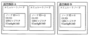
図1で例示されるように、1394機器1(100)は第1の1394バス(105)と接続されており、通信機器A(101)は第1の1394バス(105)と無線ネットワーク(107)に接続されており、1394機器2(103)と1394機器3(104)は第2の1394バス(106)に接続されており、通信機器B(102)は第2の1394バス(106)と無線ネットワーク(107)に接続されており、無線機器A(101)と無線機器B(102)は無線ネットワーク(107)で接続されているものとする。
【0023】
1394バスでは、接続機器の増減、バスリセット発生時などに、コンフィグレーションプロセスが起動され、バスの初期化、ツリーの識別、自己認識を行い各機器のノードIDが割り当てられる。これらの処理は通常、PHYチップが行い1つのPHYチップに対して1つのノードIDが割り当てられる。
【0024】
また、1394機器には、ノードIDとは別に、世の中で一意に定められる64ビットのGUIDが割り当てられており、通常、GUIDは1つのノードに必ず1つ存在するConfigROMに入っている。
【0025】
図1の例示においては、1394機器1(100)、1394機器2(103)、1394機器3(104)夫々に対して、ConfigROMは1つずつ存在し、その中にGUIDが入っている。また、1394機器1(100)は第1の1394バス(105)におけるノードIDが割り当てられ、1394機器2(103)と1394機器3(104)は第2の1394バス(106)におけるノードIDが割り当てられる。
【0026】
1394機器1(100)はGUIDが0x11111111で第1の1394バス(105)上のノードIDが0(以下、ノードIDの0の機器をノード0と省略する、ノードIDが1、2の機器も同様にノード1、ノード2と省略する)、1394機器2(103)はGUIDが0x22222222で第2の1394バス(106)上のノード1、1394機器3(104)はGUIDが0x33333333で第2の1394バス(106)上のノード2と割り付けられているものとする。
【0027】
また、通信機器A(101)には、第2の1394バス(106)上の1394機器をエミュレートするためのノードをノード1、ノード2の2つが割り付けられている。通信機器Bについても、同様に、第1の1394バス(105)上の1394機器をエミュレートするためのノード1を1つ割り付けられていることとする。尚、1394バスではノードIDは可変であり、バスリセット、機器の増減などでノードIDが変化する可能性があるが、ここでは上記の各1394機器が前記のノードIDに割り当てられた時点の例を示す。
【0028】
尚、このノードIDが異なる時点ではノードIDを置き換えて考慮すればよい。
【0029】
無線機器A(100)と無線機器B(102)の間の無線ネットワーク(107)はIEEE802.11aなどのプロトコルに従い伝送するものとする。
【0030】
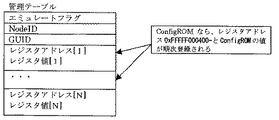
次に、通信機器A(101)、通信機器B(102)の内部構成の概要を図2に例示する。これは、通信機器A(101)が2つ、通信機器B(102)が1つのエミュレートノードを持ち、夫々のエミュレートノードについて管理テーブルが割り当てられることを示しており、初期化時は、このエミュレートノードがリピータとして動作することとする。
【0031】
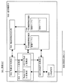
図3に、通信機器A(300)のブロック図を例示する。
【0032】
以下、図3の各ブロックの機能について説明する。
【0033】
無線I/F処理部(302)は、無線伝送におけるネゴシエーション等のPHYレベルの基本機能を備え、無線伝送のプロトコルに従ったパケットを送受信する機能を備えるものとする。
【0034】
機器情報送受信部(303)は、無線ネットワーク上の無線機器から1394バス上の機器構成情報提供の要求を受信し、その要求に応じたデータを内部機器情報記憶部(309)から取得して無線I/F(301)に送信する機能を備え、無線ネットワーク上の無線機器に接続されている1394バス上の機器構成情報を取得し外部機器情報記憶部(308)に登録を要求する機能を備え、また、無線ネットワーク上の無線機器に接続されている1394バス上の機器構成の変化の通知を受け取る機能を備えている。
【0035】
プロトコル変換部(304)は、無線I/F処理部(302)からのGUIDにより宛先と送り先が示されたAsyncパケットと同等のパケットを包括する無線パケットを受信し、GUIDで示された送信先と送信元を内部機器情報記憶部(309)と外部機器情報記憶部(308)の管理テーブルを参照しノードIDによる送信先と送信元に変換して1394バス上で伝送できるAsyncパケットに変換する機能を備え、1394I/F処理部(302)からノードIDで示された送信先と送信元が示されたAsyncパケットを受信し、内部機器情報記憶部(309)と外部機器情報記憶部(308)の管理テーブルを参照しGUIDによる送信先と送信元に変換してパケットを包括した無線パケットに変換する機能を備える。
【0036】
1394I/F処理部(305)は、プロトコル変換部(304)からAsyncパケットを受信し、Asyncパケットの送信元に応じて1394PHYに(306、307)のどちらかに送信する機能を備え、1394PHY(306,307)で受信したAsyncパケットを外部機器情報部(308)の管理テーブルを参照し情報が可能ならば応答を返送し、応答できない場合はプロトコル変換部(304)に送信する機能を備える。また、後述する管理テーブル内のエミュレートフラグが無効である場合にはリピータとして動作するように1394PHY(306,307)を制御する機能を備える。
【0037】
1394PHY(306、307)は、既存のPHYチップの機能を全て備えており、リピート、ケーブルの状態認識、バスの初期化、アービトレーションの機能を備えており、1つの1394PHYに対して1つのノードを確保するように機能する。尚、前記1394PHYは第2の1394バス(106)上の通信機器B(102)に接続されるうる1394機器の最大数個以上備えることが望ましく、本実施例では2つ備えることとする。
【0038】
外部機器情報記憶部(308)は、第2の1394バス(106)上の機器構成と各管理テーブルに第2の1394バス(106)上の1394機器のConfigROM等の機器情報を蓄積する機能を備える。尚、外部機器情報記憶部(308)は第2の1394バス(106)上の通信機器B(102)に接続されうる1394機器の最大数個以上備えることが望ましく、本実施例では2つ備えることとする。
【0039】
内部機器情報記憶部(309)は、第1の1394バス(105)上の機器構成と各管理テーブルに第1の1394バス(105)上の1394機器のConfigROM等の機器情報を蓄積する機能を備える。尚、内部情報記憶部(309)の管理テーブルは第1の1394バス(105)上の通信機器A(101)に接続されうる1394機器の最大数個以上備えることが望ましく、本実施例では1つ備えることとする。
【0040】
図4に、外部機器情報記憶部(308)、内部機器情報記憶部(309)の管理テーブルに蓄積する情報の一例を示す。
【0041】
図4に示すとおり、管理テーブルには、1394機器をエミュレートしているかどうか、つまり機器の情報の有無を示すエミュレートフラグと、ノードID、エミュレートした機器のGUIDと必要に応じてレジスタのアドレスと値を登録するための領域を持つ。本実施例ではレジスタのアドレスと値にConfigROM(レジスタアドレスは0xFFFFF000400〜)のレジスタを登録するための領域を持つこととする。
【0042】
ただし、ノードIDは、外部機器情報記憶部(308)の管理テーブルには本通信機器の1394PHY(306、307)で確保したノードIDを、内部機器情報記憶部(309)の管理テーブルには通信機器A(300)と1394バスで接続されている1394機器のノードIDを登録することとする。
上述した管理テーブルに登録する内容は、1394レジスタ空間のデータならば登録することは可能である。
【0043】
図5に通信機器Bのブロック図を例示する。
【0044】
図5の中の無線I/F処理部(502)、機器情報送受信部(503)、プロトコル変換部(504)、1394I/F処理部(505)、1394PHY(506)、外部機器情報記憶部(507)、内部機器情報記憶部(508)は図3で示した機能と同様の機能を備えることとする。
【0045】
次に、図1〜図5を元に、図6のシーケンスを用いて第1の1394バス(105)と第2の1394バス(106)上の機器を認識する場合のフローを説明する。
【0046】
まず、図1における第1の1394バス(105)において、機器の増減等においてバスリセットが発生した場合の通信機器Aにおいて1394バス上の機器を認識し、機器を認識する動作を説明する。
【0047】
第1の1394バス(105)でバスリセットが発生すると、各1394機器の1394PHYの間でバスの初期化動作が実施され、各1394機器にノードIDが割り当てられる。ノードIDが決定されると通信機器A(101)は第1の1394バス(105)上のノード0の機器から自機器を除き順番にConfigROMを読み出す、本実施例においては、ノード1とノード2は自機器に含まれるので除き、ノード0の1394機器1(100)のConfigROMを読み出す。読み出したConfigROMには通常はGUIDが含まれているので、予めGUIDを抜き出しておき、図3における内部機器情報記憶部(309)の管理テーブルに、ノード0の機器のノードIDとGUIDとConfigROMを登録し、エミュレートフラグを有効にする。
【0048】
全ての機器、本実施例ではノード0の管理テーブルの作成が終わると通信機器B(102)に第1の1394バス(105)の機器構成が変化していたならば機器構成の変化を通知する機器構成変化通知を送信する。
【0049】
次に、通信機器B(102)が、第2の1394バス(106)上の機器を認識し、機器を認識する動作についても同様に、第2の1394バス(106)でバスリセットが発生すると、各機器の1394PHYの間でバスの初期化動作が実施され、各機器のノードIDが割り当てられる。
【0050】
ノードIDが決定されると通信機器A(102)は第2の1394バス(106)上のノード0の機器から自機器を除き順番にConfigROMを読み出す。本実施例においては、ノード0は自機器に含まれるので除き、ノード1とノード2の1394機器2(103)、1394機器3(104)のConfigROMを読み出す。読み出したConfigROMには必ずGUIDが含まれているので、予めGUIDを抜き出しておき、内部機器情報記憶部(508)の管理テーブルに、調べた1394機器2(103)、1394機器3(104)のノードIDとGUIDとConfigROMを書き込み、エミュレートフラグを有効にする。全ての機器、本実施例では1394機器2と1394機器3を示す第2の1394バス(106)におけるノード1とノード2の機器の管理テーブルの作成が終わると通信機器A(101)に第2の1394バス(106)の機器構成が変化していたならば機器構成の変化を通知する機器構成変化通知を送信する。
【0051】
通信機器A(101)は、通信機器B(102)から機器構成変化通知を受け取ると、通信機器B(102)に機器構成情報を要求して通信機器B(102)の内部機器記憶部(508)の管理テーブルの情報を取得し、取得した情報を通信機器A(101)の外部機器情報記憶部(308)の管理テーブルに登録して、エミュレートフラグを有効にする。本実施例においては、通信機器A(101)に割り当てられた第1の1394バス(105)におけるノード1の外部機器情報記憶部(308)の管理テーブルに1394機器2(103)のGUIDとCofigROMを書き込み、エミュレートフラグを有効にする。
【0052】
通信機器A(101)に割り当てられた第1の1394バス(105)におけるノード2の外部機器情報記憶部(308)の管理テーブルに1394機器3(104)のGUIDとConfigROMを登録し、エミュレートフラグを有効にする。
【0053】
同様に、通信機器B(102)は、通信機器A(101)から機器構成変化通知を受け取ると、通信機器A(101)に機器構成情報を要求して通信機器A(101)の内部機器記憶部(309)の管理テーブルの情報を取得し、取得した情報を通信機器B(102)の外部機器情報記憶部(308)の管理テーブルに書き込んで、エミュレートフラグを有効にする。本実施例においては、通信機器B(102)に割り当てられた第2の1394バス(106)におけるノード0の外部機器情報記憶部(507)の管理テーブルに1394機器1(100)のGUIDとConfigROMを登録し、エミュレートフラグを有効にする。
【0054】
ここで、機器情報の登録方法において、図6のシーケンス例の変わりに図7に示すシーケンス例のように、通信機器A(101)が第2の1394バス(106)上の機器を外部機器情報記憶部(308)の管理テーブルに機器情報を登録する処理において、通信機器B(102)が第2の1394バス(106)上の1394機器の機器情報を内部機器情報記憶部(508)の管理テーブルに登録した後、通信機器B(102)が内部機器情報記憶部(508)の管理テーブルに登録した機器情報を通信機器A(101)の外部機器情報記憶部(308)に登録するように要求し、それを受けて通信機器A(101)の外部機器情報記憶部(308)の管理テーブルに登録するようにしても良い。
【0055】
上述した通り1394バスに接続された1394機器を登録することにより、通信機器A(101)、通信機器B(102)に1394バスで接続された1394機器を全て認識することが可能で、第1の1394バス(105)上に第2の1394バス(106)上の1394機器があるかのように、また第2の1394バス(106)上に第1の1394バス(105)上の機器があるかのように見せるように、第1の1394バス(105)上の1394機器を通信機器A(101)のノードにエミュレートする、また、第2の1394バス(106)上の1394機器を通信機器B(102)のノードにエミュレートする仕組みが構築できる。
【0056】
次に、上述したように1394機器を通信機器のノードにエミュレートした後に、1394機器をエミュレートした通信機器のノードにおける動作を説明するため、第1の1394機器(105)と第2の1393機器(106)がAsyncパケットを送信する実施例を図8に示す。
【0057】
ここで、送信するAsyncパケットの構造を図8に示す。
【0058】
図8の各領域の意味を示す。destination_IDは、パケット送信先のノードIDを示す。tlは、requestパケットとresponseパケットの一対のトランザクションの一致を認識するためのラベルを示す。rtは、busyのAckonwledgeを受信した時のリトライン方法に関する情報を示す。tcodeは、トランザクションパケット種別コードを示す。priは、優先度を示す。source_IDは、パケットの送信元のノードIDを示す。
【0059】
destination_offsetは、パケット送信先ノードのレジスタ空間上の目的アドレス48ビットを示す。data_dengthは、データペイロードのバイト長を示す。extended_tcodeは、トランザクションパケットの拡張種別コードを示す。header_CRCは、ヘッダー情報に対するCRCを示す。dataは、データペイロードを示す。data_CRCは、データペイロードのCRCを示す。
【0060】
図1〜図8を元に、上述した本実施例のように1394機器を通信機器のノードにエミュレートした後に、上述したAsyncパケットを送信するシーケンスの一例を図9に示す。第1の1394バス(105)上の1394機器1(100)から第2の1394バス(106)上の1394機器2(103)にAsyncパケットが送信されるまでのシーケンスを示す。
【0061】
図9のAsyncパケット送信時のシーケンス例より1394機器2(103)は第1の1394バス(105)上の通信機器A(101)のノード1にエミュレートされているので、1394機器1(100)はノード1にAsyncパケットを送信しようとして、前記Asyncパケットの送信元にノード0、送信先にノード1が、その他の領域に適当なデータが設定されたものを送信する。ノード1の属する通信機器A(101)は前記Asyncパケットを受信し、内部機器情報記憶部(309)のノード0に対応する管理テーブルを参照してGUIDを取得し、送信元のノードIDをGUIDに変換する。外部機器情報記憶部(308)のノード1に対応する管理テーブルを参照してGUIDを取得し、送信先のノードIDをGUIDに変換する。本実施例では、送信元のノード0を1394機器1のGUIDである0x11111111に、送信先のノード1を1394機器2のGUIDである0x22222222に変換する。
【0062】
図10に送信元と送信先がGUIDに変換されたAsyncパケットの一例を示す。これは、受信したAsyncパケットの先頭にDestination_GUIDとSource_GUIDを付加したものである。Destination_GUIDは、送信先の1394機器のGUIDを示す。Source_GUIDは、送信元の1394機器のGUIDを示す。つまり、Destination_GUIDに1394機器2のGUIDの0x22222222が、Source_GUIDに1394機器1のGUIDの0x11111111が設定される。
【0063】
次にGUIDに変換されたAsyncパケットは通信機器B(102)に無線伝送するための無線パケットのプロトコルに包括されて通信機器B(102)に送信される。通信機器B(102)は、受信した無線パケットよりAsyncパケットを抜き出し、送信元のGUIDを通信機器B(102)の外部機器情報(507)の管理テーブルから参照し、第2の1394バス上にエミュレートされた1394機器1(100)に割り当てられたノードIDに変換して、source_IDに設定する。同時に送信先のGUIDを通信機器Bの内部機器情報記憶部(509)の管理テーブルから参照し、第2の1394バス(106)上で1394機器2(103)に割り当てられているノードIDに変換し、source_IDに設定する。本実施例においては、図7のAsyncパケットにおいて、destination_IDに1394機器1(100)がエミュレートされたノード1が、source_IDに1394機器2(103)のノード0が設定されることになる。
【0064】
上述したシーケンスより1394機器1(100)は、第1の1394バス(105)上の通信機器A(101)に1394機器2(103)をエミュレートしたノード1にAsyncパケットを送信しており、また、1394機器2(103)は、第2の1394バス(106)上の通信機器B(102)に1394機器1(100)をエミュレートしたノードからAsyncパケットを受信しており、第1の1394バス(105)と第2の1394バス(106)との間に無線通信が含まれていることを意識せずにAsyncパケットを送信することができる。
【0065】
次に、図1〜図8を元に、図11において、1394機器1(100)から、通信機器A(101)のノード1にエミュレートされた1394機器2のConfigROMを読み出す場合のシーケンスの一例を示す。
【0066】
この場合、図8に示すAsyncパケットにおいて、destination_IDにノード1、source_IDにノード0、tcodeに読み出しのリクエストであるREAD_REQUESTを設定、Destination_offsetにConfigROMの配置されるレジスタアドレス(通常、0xFFFFF000400〜)を設定、必要ならばdata_lengthに読み出したいConfigROMのバイト長を設定する。
【0067】
前記のように設定したREAD_REQUESTのAsyncパケットを送信することが送信先のConfigROMのデータを読み出すことになる。
【0068】
図11に示すシーケンス例のとおり、ノード0である1394機器1(100)から通信機器A(101)の1394機器2(103)をエミュレートしたノード1に前記READ_REQUESTのAsyncパケットを送信すると、通信機器A(101)は前記Asyncパケットを受信して1394機器2(103)をエミュレートしたノード1に対応する外部機器情報記憶部(308)の管理テーブルを参照して、前記管理テーブルに前記destination_offsetで設定されているレジスタアドレスが登録されていることを確認すると、前記レジスタアドレスの値を参照してREAD_RESPONSEのAsyncパケットを作成してノード1に送信する。つまり、1394機器2(103)をエミュレートした通信機器A(101)のノード1のConfigROMの読み出し要求に対して、通信機器A(101)から直接に応答することが出来る。
【0069】
上述した処理により、第1の1394バス(105)上の1394機器1(100)から、第2の1394バス(106)上の1394機器2(103)のConfigROMを読み出すのに、Asyncパケットを第2の1394バス(106)の1394機器2(103)に送信することなく応答を要求するAsyncパケットに対して、その応答を返送することができ、通信時間を短縮することができる。
【0070】
尚、本実施例においては、複数の1394PHYを持つことにより、1394PHYの数個だけ1394バス上のノードを確保するという既存のPHYチップの性能を利用した手法を採用しているので、1394PHYの数=確保するノードの数という図式が成り立つが、複数のノードを確保する手段は1394PHYの数を増やすことに特定するものではない。例えば、1つの1394PHYにおいても、擬似的に複数種類のセルフIDパケットを送受信することで1つ1394PHYでも複数のノードを確保することは可能であるし、このような方法でノードを確保しても良い。
【0071】
また、本実施例においては、上述したネットワーク構成以上の機器が、つまり通信機器A(101)と1394バスで接続されるのは1台まで、通信機器B(102)と1394バスで接続されるのは2台までと想定した例であったため、1394PHYの数、管理テーブルの数を限定しているが、確保するノードの数、管理テーブルの数を限定する必要はない。しかし、エミュレートする1394機器の数よりも、確保するノードの数、管理テーブルの数が多い必要がある。
【0072】
また、遠隔の1394バス上の1394機器の数よりも、通信機器で確保するノードの数は多いことが望ましいが、無線ネットワークで取得してきた遠隔の1394バス上の機器要素の中からエミュレートする(Asyncパケットを送信できる)1394機器を取捨選択することにより、遠隔の1394バス上の1394機器の数よりも、通信機器で確保するノードの数を少なくすることも可能である。
【0073】
また、管理テーブルに配置する情報は、本実施例で示した情報に限定するものではなく、ConfigROM以外のデータを配置することも可能であり、ConfigROM以外のレジスタに関してもエミュレートしたノードから直接に応答することも可能である。
【0074】
(第2の実施形態)
次に第2の実施形態を示す。
【0075】
特に断りがない限り第1の実施形態と同じシステムにおいて、同じ機能を有するものとする。
【0076】
図12に第1の1394バス(105)と第2の1394バス(106)の間に無線ネットワーク(107)が接続された通信システムの一例を示す。
【0077】
図12で例示されるように、1394機器1(1200)は第1の1394バス(1205)と接続されており、通信機器A(1201)は第1の1394バス(1205)と無線ネットワーク(1207)に接続されており、1394機器2(1203)と1394機器3(1204)は第2の1394バス(1206)に接続されており、通信機器B(1202)は第2の1394バス(1206)と無線ネットワーク(1207)に接続されており、無線機器A(1201)と無線機器B(1202)は無線ネットワーク(1207)で接続されているものとする。
【0078】
図12の例示においては、1394機器1(1200)、1394機器2(1203)、1394機器3(1204)夫々に対して、ConfigROMは1つずつ存在し、その中にGUIDが入っている。
【0079】
また、1394機器1(1200)は第1の1394バス(1205)におけるノードIDが割り当てられ、1394機器2(1203)と1394機器3(1204)は第2の1394バス(1206)におけるノードIDが割り当てられる。1394機器1(1200)はGUIDが0x11111111で第1の1394バス(1205)上のノードIDが0(以下、ノードIDの0の機器をノード0と省略する、ノードIDが1、2の機器も同様にノード1、ノード2と省略する)、1394機器2(1203)はGUIDが0x22222222で第2の1394バス(1206)上のノード1、1394機器3(1204)はGUIDが0x33333333で第2の1394バス(1206)上のノード2と割り付けられているものとする。また、通信機器A(1201)には、第2の1394バス(1206)上の1394機器をエミュレートするためのノードをノード1、ノード2の2つと、通信機器A(1201)自身の機能を司るノード3が割り付けられていることとし、通信機器A(1201)自身の機能を司るノード3に関しては0xAAAAAAAAのGUIDとする。通信機器Bについても、同様に、第1の1394バス(1205)上の1394機器をエミュレートするためのノード1を割付ら手入ることとする。
【0080】
尚、1394バスではノードIDは可変であり、バスリセット、機器の増減などでノードIDが変化する可能性があるが、ここでは上記の各1394機器が前記のノードIDに割り当てられた時点の例を示す。尚、このノードIDが異なる時点ではノードIDを置き換えて考慮すればよい。
【0081】
無線機器A(1200)と無線機器B(1202)の間の無線ネットワーク(1207)はIEEE802.11aなどのプロトコルに従い伝送するものとする。
【0082】
次に、図13に通信機器A(1201)、通信機器B(1202)の内部構成の概要を例示する。これは、通信機器A(1201)が2つ、通信機器B(1202)が1つのエミュレートノードを持ち、夫々のエミュレートノードについて管理テーブルが割り当てられることを示しており、初期化時は、このエミュレートノードがリピータとして動作することとする。付け加えて、通信機器A(1201)には自身のノードを示すためのノードを1つ持ち管理テーブルも1つ割り当てられることを示している。
【0083】
次に図14において、自身をノードとして持つ通信機器A(1201)のブロック図を示す。
【0084】
このブロック図は、第1の実施形態で説明した図3の通信機器A(300)のブロック図と各機能は同じであり、通信機器A(1400)自身のノードを確保するための1394PHY(1408)と、通信機器A(1400)自身の情報を登録するための内部機器情報記憶部内(1410)の管理テーブル(1410−b)と、通信機器自身のノードの1394レジスタ(1412)と、通信機器A(1400)自身の機能を制御するための機器制御部(1411)とが追加され、1394I/F(1405)に機能が追加される。
【0085】
前記1394PHY(1408)は、第1の実施形態で示したとおり従来のPHYチップの機能を備えており、1394バス上に通信機器A(1400)自身のノードを確保するために使用する。
【0086】
前記管理テーブル(1410−b)は、通信機器A(1400)自身を第1の1394バス(1205)上の構成要素に加えるために使用する。
【0087】
前記1394レジスタ(1411)は、通信機器A(1400)自身を表すノードの1394レジスタが記憶されている。この1394レジスタの中にConfigROM等の1394レジスタ値が記憶されており、1394I/F処理部(1405)からのAsyncパケットに応じて、読み出し、書込み等が行われる。
【0088】
前記機器制御(1412)は、通信機器A(1400)自身を表すノードに対して、第1の1394バス(1205)上の任意の1394機器からAsyncパケットを受信し1394レジスタが操作された場合に、その操作に対応する制御を行う。例えば、AV/Cコマンドの場合には、1394レジスタのAVC_COMMANDレジスタと呼ばれるレジスタアドレスの領域にコマンドデータを書き込むように要求するAsyncパケットが受信し、データに従いノードの機器を制御し、その制御結果をAV/Cコマンドを送信してきたノードのAVC_RESPONSEレジスタと呼ばれる領域に書き込むAsyncパケットをAV/Cコマンドを送信してきたノードに送信する。
【0089】
この時、機器制御部(1412)は1394レジスタのAVC_COMMANDレジスタの内容を読み取り所定の制御を行い、その応答をAV/Cコマンドを送信した1394レジスタのAVC_RESPONEレジスタに書き込むようなAsyncパケットを送信するよう1394I/Fに要求する。
【0090】
前記1394I/Fは、第1の実施形態における機能に加え、受信したAsyncパケットの送信先のノードが通信機器A(1400)自身のノードである場合には、1394レジスタにAsycnパケットの内容に応じて、読み出し、書込みの処理を要求する。また、機器制御部からのAsyncパケット送信の要求に応じて、1394バス上にAsyncパケットを送信する。
【0091】
上記のように通信機器自身のノードを持つことで、通信機器自身を操作する場合に便利である。例えば、AV/Cコマンドにより、通信機器の内部機器情報記憶部、外部機器情報記憶部の管理テーブルの情報を読み出したり、前記管理テーブルに登録する情報を選択したり、前記管理テーブルに登録する機器を選択したりできる。また、無線I/Fの能力に依存するような操作、例えば、無線機器の電源をON/OFFに切り替えたり、無線I/Fの機能を有効/無効に切り替えたり、無線ネットワークで接続する通信機器を選択したりなど、様様な操作や状態の取得が可能になる。
【0092】
尚、本実施例では通信機器Aのみ自身のノードを持つような例を示しているが、通信機器A,通信機器Bともに自身のノードを持つようにしても良い。
【0093】
【発明の効果】
前記通信機器を設置することにより、1394バス上の他のプロトコルとのブリッジに対応していない既存の1394機器から、別のプロトコルのネットワークに接続された異なる1394バス上の複数の1394機器を、同じ1394バス上の機器として従来通りの方法で操作することが可能になる。
【図面の簡単な説明】
【図1】通信システムの一例である。
【図2】通信機器Aと通信機器Bの概略例である。
【図3】通信機器Aのブロック図である。
【図4】管理テーブルの一例である。
【図5】通信機器Bのブロック図である。
【図6】機器認識と管理テーブル登録のシーケンス例1である。
【図7】機器認識と管理テーブル登録のシーケンス例2である。
【図8】Asyncパケットである。
【図9】Asyncパケット送信時のシーケンス例である。
【図10】GUIDを付加したAsyncパケットの一例である。
【図11】ConfigROMのREAD処理のシーケンス例である。
【図12】自身をノードに持つ通信機器を含む通信システムの一例である。
【図13】自身をノードに持つ通信機器Aと通信機器Bの概略例である。
【図14】自身をノードに持つ通信機器Aのブロック図である。
【符号の説明】
100:1394機器1
101:通信機器A
102:通信機器B
103:1394機器2
104:1394機器3
105:第1の1394バス
106:第2の1394バス
107:無線ネットワーク
300:無線機器A
301:無線I/F
302:無線I/F処理部
303:機器情報送受信部
304:プロトコル変換部
305:1394I/F処理部
306:1394PHY
307:1394PHY
308:外部機器情報記憶部
309:内部機器情報記憶部
310:IEEE1394バス
500:無線機器B
501:無線I/F
502:無線I/F処理部
503:機器情報送受信部
504:プロトコル変換部
505:1394I/F処理部
506:1394PHY
507:外部機器情報記憶部
508:内部機器情報記憶部
509:IEEE1394バス
1200:1394機器1
1201:通信機器A
1202:通信機器B
1203:1394機器2
1204:1394機器3
1205:第1の1394バス
1206:第2の1394バス
1207:無線ネットワーク
1400:無線機器A
1401:無線I/F
1402:無線I/F処理部
1403:機器情報送受信部
1404:プロトコル変換部
1405:1394I/F処理部
1406、1407,1408:1394PHY
1409:外部機器情報記憶部
1409−a、1409−b:管理テーブル
1410:内部機器情報記憶部
1410−a、1210−b:管理テーブル
1411:1394レジスタ
1412:機器制御部
1413:IEEE1394バス[0001]
TECHNICAL FIELD OF THE INVENTION
According to the present invention, in a system in which a first 1394 bus and a second 1394 bus are connected by a third network, a communication device that exists on the second 1394 bus and communicates with a node of the third network is used. 1 which is on the 1394 bus and communicates with a node of the third network.
[0002]
[Prior art]
In recent years, 1394 has been in the spotlight as a network for connecting AV devices, and various 1394-compatible products such as BS digital tuners, DVHS decks, and DV cameras have already been released.
[0003]
Attempts have also been made to implement a 1394 bus on a broadband radio, and there are radio communication protocols such as Wireless 1394 and 1394 over 802.11, and a 1394 bus can be constructed over the radio by using the technology shown here. A method for realizing connection between a wired 1394 bus and a wireless 1394 bus as a network through a bridge is discussed.
[0004]
In order to communicate with a wireless terminal from a wired 1394 bus as disclosed in
[0005]
[Patent Document 1]
JP 2000-156683 A
[0006]
[Problems to be solved by the invention]
However, in the case where a network other than the 1394 bus exists between the 1394 buses, a 1394 bridge is required, so that a current 1394 device that does not support bridges must be connected to a 1394 bus with a different protocol network. The above 1394 device cannot be operated.
[0007]
In addition, if a method as disclosed in
[0008]
In addition, since communication devices connected to a network such as wireless are emulated as subunits of communication devices on the 1394 bus, communication can be performed only with devices that can be connected to the network.
[0009]
[Means for Solving the Problems]
In order to solve the above problems, the present invention has taken the following measures.
[0010]
In other words, the communication device according to the present invention is connected to the first 1394 bus in a system in which the first IEEE 1394 (hereinafter abbreviated as 1394) bus and the second 1394 bus are connected by the third network. 1394 interface means, third interface means connected to a third network, means for recognizing each node on the first 1394 bus as a component on the first 1394 bus, and A third interface connected to a third network, a 1394 interface connected to a second 1394 bus, and each node on the second 1394 bus connected to a second 1394 bus. Means for recognizing components on the 1394 bus, and components recognized by the recognizing means. Acquiring the components on the second 1394 bus through the third interface means from the communication device having the means for disclosing through the third interface means, and connecting the nodes on the second 1394 bus to the first 1394 bus. A means to emulate as a node is provided.
[0011]
Further, the communication device has a function of emulating a plurality of nodes on the second 1394 bus obtained through the third interface means as a plurality of nodes on the first 1394 bus.
[0012]
In the communication device, the component on the second 1394 bus acquired through the third interface means includes device information of each node (GUID of each device, register address and value, subunit configuration, etc.). did.
[0013]
In the communication device, when an asynchronous packet (hereinafter abbreviated as an Async packet) is transmitted from an arbitrary node on the first 1394 bus to a node emulated by the communication device, the second 1394 bus A function of transmitting an equivalent Async packet to the above node is provided.
[0014]
Further, in the communication device, when an Async packet is transmitted from an arbitrary node on the first 1394 bus to an emulated node, a response is created and returned in the emulated node. .
[0015]
Further, the communication device has its own function as a node in addition to the emulation node on the second 1394 bus.
[0016]
The above-described means is to provide a communication device with a plurality of 1394 PHYs and emulate a 1394 device on a remote 1394 bus as a node for each 1394 PHY, thereby transmitting an Async packet to the emulated node (AV / AV). (Including the transmission and reception of the C command), an equivalent Async packet can be transmitted to the 1394 device on the remote 1394 bus corresponding to the emulated node. By doing so, the existing 1394 device transmits the Async packet to the node emulated by the communication device on the same 1394 bus, thereby transmitting the Async packet to the 1394 device on the remote 1394 bus. This makes it possible to operate 1394 devices on a remote 1394 bus in the same manner as the conventional operation method.
[0017]
Here, the 1394 PHY refers to an existing PHY chip having basic functions of the 1394 PHY layer, such as repeat, cable state recognition, bus initialization, and arbitration.
[0018]
Further, by copying register information such as a ConfigurationROM (hereinafter abbreviated as ConfigROM) of the 1394 device to a node in a communication device emulating the 1394 device on a remote 1394 bus, the Async packet transmission can be performed. An Async packet (READ_RESPONSE, etc.) for a response to a part (READ_REQUEST, etc. of ConfigROM) can be created and returned by an emulated node in a communication device that has received the Async packet, thereby shortening the transmission path. Also becomes possible.
[0019]
BEST MODE FOR CARRYING OUT THE INVENTION
Hereinafter, embodiments of the present invention will be described with reference to the drawings.
[0020]
(1st Embodiment)
A first embodiment of the present invention will be described.
[0021]
FIG. 1 shows an example of a communication system in which a wireless network (107) is connected between a first 1394 bus (105) and a second 1394 bus (106).
[0022]
As illustrated in FIG. 1, the 1394 device 1 (100) is connected to the first 1394 bus (105), and the communication device A (101) is connected to the first 1394 bus (105) and the wireless network (107). ), The 1394 device 2 (103) and the 1394 device 3 (104) are connected to the second 1394 bus (106), and the communication device B (102) is connected to the second 1394 bus (106). It is assumed that the wireless device A (101) and the wireless device B (102) are connected by the wireless network (107).
[0023]
In the 1394 bus, a configuration process is started when the number of connected devices increases or decreases, or when a bus reset occurs. The bus initialization, tree identification, and self-recognition are performed, and a node ID of each device is assigned. These processes are normally performed by the PHY chip, and one node ID is assigned to one PHY chip.
[0024]
In addition to the node ID, a 1394 device is assigned a 64-bit GUID uniquely determined in the world. Usually, one GUID is stored in the ConfigROM that always exists in one node.
[0025]
In the example of FIG. 1, there is one ConfigROM for each of the 1394 device 1 (100), the 1394 device 2 (103), and the 1394 device 3 (104), and the GUID is contained therein. The 1394 device 1 (100) is assigned a node ID on the first 1394 bus (105), and the 1394 device 2 (103) and the 1394 device 3 (104) have node IDs on the second 1394 bus (106). Assigned.
[0026]
The 1394 device 1 (100) has a GUID of 0x11111111 and a node ID on the first 1394 bus (105) of 0 (hereinafter, a device having a node ID of 0 is abbreviated as a
[0027]
The communication device A (101) has two nodes, ie, a
[0028]
When the node IDs are different, the node IDs may be replaced and considered.
[0029]
The wireless network (107) between the wireless device A (100) and the wireless device B (102) transmits data according to a protocol such as IEEE802.11a.
[0030]
Next, an outline of the internal configuration of the communication device A (101) and the communication device B (102) is illustrated in FIG. This indicates that the communication device A (101) has two emulation nodes and the communication device B (102) has one emulation node, and a management table is assigned to each emulation node. This emulated node operates as a repeater.
[0031]
FIG. 3 illustrates a block diagram of the communication device A (300).
[0032]
Hereinafter, the function of each block in FIG. 3 will be described.
[0033]
The wireless I / F processing unit (302) has a basic function of a PHY level such as negotiation in wireless transmission, and has a function of transmitting and receiving a packet according to a wireless transmission protocol.
[0034]
The device information transmission / reception unit (303) receives a request for provision of device configuration information on the 1394 bus from a wireless device on the wireless network, acquires data corresponding to the request from the internal device information storage unit (309), and performs wireless communication. It has a function of transmitting to the I / F (301), a function of acquiring device configuration information on the 1394 bus connected to the wireless device on the wireless network, and requesting registration to the external device information storage unit (308). It also has a function of receiving notification of a change in device configuration on a 1394 bus connected to wireless devices on a wireless network.
[0035]
The protocol conversion unit (304) receives a wireless packet including a packet equivalent to an Async packet whose destination and destination are indicated by the GUID from the wireless I / F processing unit (302), and transmits the destination indicated by the GUID. With reference to the management tables of the internal device information storage unit (309) and the external device information storage unit (308), the source and destination are converted into the destination and source by the node ID, and are converted into Async packets that can be transmitted on the 1394 bus. It has a function, receives an Async packet indicating the transmission destination and transmission source indicated by the node ID from the 1394 I / F processing unit (302), and stores the internal device information storage unit (309) and the external device information storage unit (308). ), A function of referring to the management table and converting the data into a transmission destination and a transmission source based on the GUID to convert the packet into a wireless packet including the packet.
[0036]
The 1394 I / F processing unit (305) has a function of receiving an Async packet from the protocol conversion unit (304) and transmitting the Async packet to one of (306, 307) according to the source of the Async packet. 306, 307), by referring to the management table of the external device information unit (308), returning a response if the information is possible, and transmitting a response to the protocol conversion unit (304) if the response is not possible. Further, a function is provided for controlling the 1394 PHY (306, 307) so as to operate as a repeater when an emulation flag in a management table described later is invalid.
[0037]
The 1394 PHY (306, 307) has all the functions of the existing PHY chip, and has the functions of repeat, cable status recognition, bus initialization, and arbitration. One 1394 PHY has one node. It works to ensure. The 1394 PHY is desirably provided with at least the maximum number of 1394 devices that can be connected to the communication device B (102) on the second 1394 bus (106). In this embodiment, two 1394 PHYs are provided.
[0038]
The external device information storage unit (308) has a function of storing the device configuration on the second 1394 bus (106) and device information such as ConfigROM of the 1394 device on the second 1394 bus (106) in each management table. Prepare. The external device information storage unit (308) desirably includes at least the maximum number of 1394 devices that can be connected to the communication device B (102) on the second 1394 bus (106). In the present embodiment, two are provided. It shall be.
[0039]
The internal device information storage unit (309) has a function of accumulating device information such as ConfigROM of the 1394 device on the first 1394 bus (105) in the device configuration on the first 1394 bus (105) and each management table. Prepare. The management table of the internal information storage unit (309) desirably includes at least the maximum number of 1394 devices that can be connected to the communication device A (101) on the first 1394 bus (105). It shall be prepared.
[0040]
FIG. 4 shows an example of information stored in the management tables of the external device information storage unit (308) and the internal device information storage unit (309).
[0041]
As shown in FIG. 4, the management table contains an emulation flag indicating whether or not the 1394 device is emulated, that is, a node ID, a GUID of the emulated device, and a register of the register as necessary. It has an area for registering addresses and values. In the present embodiment, it is assumed that there is an area for registering a register of ConfigROM (register address is 0xFFFFF000400-) in register address and value.
[0042]
However, as the node ID, the node ID secured by the 1394 PHY (306, 307) of the communication device is stored in the management table of the external device information storage unit (308), and the node ID is stored in the management table of the internal device information storage unit (309). The node ID of the 1394 device connected to the device A (300) via the 1394 bus is registered.
The contents to be registered in the management table described above can be registered if the data is in the 1394 register space.
[0043]
FIG. 5 illustrates a block diagram of the communication device B.
[0044]
The wireless I / F processing unit (502), the device information transmitting / receiving unit (503), the protocol conversion unit (504), the 1394 I / F processing unit (505), the 1394 PHY (506), the external device information storage unit ( 507), the internal device information storage unit (508) has the same function as the function shown in FIG.
[0045]
Next, a flow for recognizing devices on the first 1394 bus (105) and the second 1394 bus (106) will be described with reference to FIGS.
[0046]
First, an operation of recognizing a device on the 1394 bus and recognizing the device in the communication device A when a bus reset occurs in the first 1394 bus (105) in FIG.
[0047]
When a bus reset occurs on the first 1394 bus (105), a bus initialization operation is performed between 1394 PHYs of each 1394 device, and a node ID is assigned to each 1394 device. When the node ID is determined, the communication device A (101) sequentially reads the ConfigROM from the device of the
[0048]
When the creation of the management table of all the devices, in this embodiment, the
[0049]
Next, when the communication device B (102) recognizes the device on the second 1394 bus (106) and recognizes the device, similarly, when a bus reset occurs on the second 1394 bus (106), A bus initialization operation is performed between the 1394 PHYs of each device, and a node ID of each device is assigned.
[0050]
When the node ID is determined, the communication device A (102) sequentially reads the ConfigROM from the devices of the
[0051]
Upon receiving the device configuration change notification from the communication device B (102), the communication device A (101) requests device configuration information from the communication device B (102), and stores the internal device storage unit (508) of the communication device B (102). ), The acquired information is registered in the management table of the external device information storage unit (308) of the communication device A (101), and the emulation flag is made valid. In the present embodiment, the management table of the external device information storage unit (308) of the
[0052]
The GUID and ConfigROM of the 1394 device 3 (104) are registered in the management table of the external device information storage unit (308) of the
[0053]
Similarly, upon receiving the device configuration change notification from the communication device A (101), the communication device B (102) requests device configuration information from the communication device A (101) and stores the internal device storage of the communication device A (101). The information of the management table of the communication unit B (102) is obtained, and the obtained information is written in the management table of the external device information storage unit (308) of the communication device B (102), thereby enabling the emulation flag. In the present embodiment, the GUID and ConfigROM of the 1394 device 1 (100) are stored in the management table of the external device information storage unit (507) of the
[0054]
Here, in the device information registration method, instead of the sequence example of FIG. 6, the communication device A (101) sets the device on the second 1394 bus (106) to the external device information as in the sequence example of FIG. In the process of registering the device information in the management table of the storage unit (308), the communication device B (102) stores the device information of the 1394 device on the second 1394 bus (106) in the internal device information storage unit (508). After the registration in the table, the communication device B (102) registers the device information registered in the management table of the internal device information storage unit (508) in the external device information storage unit (308) of the communication device A (101). The request may be received and registered in the management table of the external device information storage unit (308) of the communication device A (101).
[0055]
By registering the 1394 devices connected to the 1394 bus as described above, it is possible to recognize all the 1394 devices connected to the communication device A (101) and the communication device B (102) via the 1394 bus. As if there were 1394 devices on the second 1394 bus (106) on the 1394 bus (105), and devices on the first 1394 bus (105) on the second 1394 bus (106). The 1394 device on the first 1394 bus (105) is emulated to the node of the communication device A (101) so that it appears as if it is, and the 1394 device on the second 1394 bus (106) is emulated. A mechanism for emulating the node of the communication device B (102) can be constructed.
[0056]
Next, after the 1394 device is emulated as a communication device node as described above, the first 1394 device (105) and the second 1394 device will be described in order to describe the operation at the communication device node that emulates the 1394 device. FIG. 8 shows an embodiment in which the device (106) transmits an Async packet.
[0057]
Here, the structure of the Async packet to be transmitted is shown in FIG.
[0058]
The meaning of each area in FIG. 8 will be described. destination_ID indicates the node ID of the packet transmission destination. tl indicates a label for recognizing a match between a pair of transactions of a request packet and a response packet. rt indicates information about the retry line method at the time of receiving the busy Acknowledge. tcode indicates a transaction packet type code. pri indicates the priority. source_ID indicates the node ID of the packet transmission source.
[0059]
destination_offset indicates the destination address 48 bits in the register space of the packet destination node. data_dength indicates the byte length of the data payload. extended_tcode indicates an extension type code of the transaction packet. header_CRC indicates a CRC for header information. data indicates a data payload. data_CRC indicates the CRC of the data payload.
[0060]
FIG. 9 shows an example of a sequence for transmitting the above-mentioned Async packet after emulating the 1394 device to the node of the communication device as in the above-described embodiment based on FIGS. The sequence from when the Async packet is transmitted from the 1394 device 1 (100) on the first 1394 bus (105) to the 1394 device 2 (103) on the second 1394 bus (106) is shown.
[0061]
Since the 1394 device 2 (103) is emulated by the
[0062]
FIG. 10 shows an example of an Async packet in which the transmission source and the transmission destination have been converted into GUIDs. This is obtained by adding Destination_GUID and Source_GUID to the head of the received Async packet. Destination_GUID indicates the GUID of the
[0063]
Next, the Async packet converted to the GUID is included in the protocol of a wireless packet for wireless transmission to the communication device B (102) and transmitted to the communication device B (102). The communication device B (102) extracts the Async packet from the received wireless packet, refers to the GUID of the transmission source from the management table of the external device information (507) of the communication device B (102), and places it on the second 1394 bus. It converts the emulated 1394 device 1 (100) into a node ID assigned to it and sets it as source_ID. At the same time, the GUID of the transmission destination is referred to from the management table of the internal device information storage unit (509) of the communication device B, and is converted into the node ID assigned to the 1394 device 2 (103) on the second 1394 bus (106). And set it to source_ID. In the present embodiment, in the Async packet of FIG. 7, the
[0064]
According to the above-described sequence, the 1394 device 1 (100) transmits an Async packet to the
[0065]
Next, based on FIGS. 1 to 8, an example of a sequence in FIG. 11 in which the Config ROM of the 1394
[0066]
In this case, in the Async packet shown in FIG. 8, the destination_ID is set to
[0067]
Transmission of the READ_REQUEST Async packet set as described above reads out the data in the ConfigROM of the transmission destination.
[0068]
As in the sequence example shown in FIG. 11, when the Async packet of the READ_REQUEST is transmitted from the 1394 device 1 (100) that is the
[0069]
By the above-described processing, the Async packet is read from the 1394 device 1 (100) on the first 1394 bus (105) to read the ConfigROM of the 1394 device 2 (103) on the second 1394 bus (106). In response to an Async packet requesting a response without transmitting to the 1394 device 2 (103) of the second 1394 bus (106), the response can be returned, and the communication time can be reduced.
[0070]
In the present embodiment, since a method using the performance of the existing PHY chip is adopted, in which a plurality of 1394 PHYs are provided and only a few 1394 PHY nodes are secured on the 1394 bus, the number of 1394 PHYs is reduced. Although the following equation holds: the number of nodes to be secured, the means for securing a plurality of nodes does not specify increasing the number of 1394 PHYs. For example, even in one 1394 PHY, it is possible to secure a plurality of nodes with one 1394 PHY by transmitting and receiving a plurality of types of self ID packets in a pseudo manner. good.
[0071]
Further, in this embodiment, up to one device having the above-mentioned network configuration, that is, the communication device A (101) is connected to the communication device A (101) by the 1394 bus, and the communication device B (102) is connected to the communication device B (102) by the 1394 bus. This is an example in which up to two devices are assumed, so the number of 1394 PHYs and the number of management tables are limited, but the number of nodes to be secured and the number of management tables need not be limited. However, the number of nodes to be reserved and the number of management tables need to be larger than the number of 1394 devices to be emulated.
[0072]
It is desirable that the number of nodes secured by the communication device is larger than the number of 1394 devices on the remote 1394 bus. However, emulation is performed from among the device elements on the remote 1394 bus acquired through the wireless network. By selecting 1394 devices (which can transmit Async packets), it is also possible to reduce the number of nodes secured by communication devices compared to the number of 1394 devices on a remote 1394 bus.
[0073]
Further, the information arranged in the management table is not limited to the information described in the present embodiment, and data other than the ConfigROM can be arranged, and registers other than the ConfigROM can be directly sent from the emulated node. It is also possible to respond.
[0074]
(Second embodiment)
Next, a second embodiment will be described.
[0075]
Unless otherwise specified, the same system as in the first embodiment has the same function.
[0076]
FIG. 12 shows an example of a communication system in which a wireless network (107) is connected between a first 1394 bus (105) and a second 1394 bus (106).
[0077]
As illustrated in FIG. 12, the 1394 device 1 (1200) is connected to the first 1394 bus (1205), and the communication device A (1201) is connected to the first 1394 bus (1205) and the wireless network (1207). ), The 1394 device 2 (1203) and the 1394 device 3 (1204) are connected to the second 1394 bus (1206), and the communication device B (1202) is connected to the second 1394 bus (1206). And the wireless device A (1201) and the wireless device B (1202) are connected by the wireless network (1207).
[0078]
In the example of FIG. 12, one ConfigROM exists for each of the 1394 device 1 (1200), the 1394 device 2 (1203), and the 1394 device 3 (1204), and the GUID is contained therein.
[0079]
The 1394 device 1 (1200) is assigned a node ID on the first 1394 bus (1205), and the 1394 device 2 (1203) and the 1394 device 3 (1204) have node IDs on the second 1394 bus (1206). Assigned. The 1394 device 1 (1200) has a GUID of 0x11111111 and a node ID of 0 on the first 1394 bus (1205) (hereinafter, a device with a node ID of 0 is abbreviated as a
[0080]
In the 1394 bus, the node ID is variable, and there is a possibility that the node ID changes due to a bus reset, an increase or decrease in the number of devices, and the like. Here, an example at the time when each of the above 1394 devices is assigned to the node ID is described. Is shown. When the node IDs are different, the node IDs may be replaced and considered.
[0081]
The wireless network (1207) between the wireless device A (1200) and the wireless device B (1202) transmits data according to a protocol such as IEEE802.11a.
[0082]
Next, FIG. 13 illustrates an outline of an internal configuration of the communication device A (1201) and the communication device B (1202). This indicates that the communication device A (1201) has two emulation nodes, and the communication device B (1202) has one emulation node, and a management table is allocated to each emulation node. This emulated node operates as a repeater. In addition, it indicates that the communication device A (1201) has one node for indicating its own node and one management table is also allocated.
[0083]
Next, FIG. 14 shows a block diagram of a communication device A (1201) having itself as a node.
[0084]
This block diagram has the same functions as the block diagram of the communication device A (300) of FIG. 3 described in the first embodiment, and a 1394 PHY (1408) for securing a node of the communication device A (1400) itself. ), A management table (1410-b) in the internal device information storage unit (1410) for registering information of the communication device A (1400) itself, a 1394 register (1412) of the communication device's own node, and a communication device. A (1400) has a device control unit (1411) for controlling its own function, and a function is added to the 1394 I / F (1405).
[0085]
The 1394 PHY (1408) has the function of the conventional PHY chip as shown in the first embodiment, and is used to secure the node of the communication device A (1400) itself on the 1394 bus.
[0086]
The management table (1410-b) is used to add the communication device A (1400) itself to a component on the first 1394 bus (1205).
[0087]
The 1394 register (1411) stores the 1394 register of the node representing the communication device A (1400) itself. A 1394 register value such as a Config ROM is stored in the 1394 register, and reading, writing, and the like are performed according to an Async packet from the 1394 I / F processing unit (1405).
[0088]
The device control (1412) receives an Async packet from an arbitrary 1394 device on the first 1394 bus (1205) for a node representing the communication device A (1400) and operates the 1394 register. And control corresponding to the operation. For example, in the case of an AV / C command, an Async packet requesting to write command data in a register address area called an AVC_COMMAND register of the 1394 register is received, and the device of the node is controlled according to the data. An Async packet to be written into an area called an AVC_RESPONSE register of the node that has transmitted the AV / C command is transmitted to the node that has transmitted the AV / C command.
[0089]
At this time, the device control unit (1412) reads the contents of the AVC_COMMAND register of the 1394 register, performs predetermined control, and transmits an Async packet that writes the response to the AVC_RESPONE register of the 1394 register that transmitted the AV / C command. 1394 I / F.
[0090]
In addition to the function of the first embodiment, when the destination node of the received Async packet is the node of the communication device A (1400) itself, the 1394 I / F stores the content of the Async packet in the 1394 register. Request read and write processing. In addition, in response to a request for transmission of an Async packet from the device control unit, an Async packet is transmitted on the 1394 bus.
[0091]
Having the node of the communication device itself as described above is convenient when operating the communication device itself. For example, an AV / C command reads information in a management table of an internal device information storage unit and an external device information storage unit of a communication device, selects information to be registered in the management table, and a device to be registered in the management table. Or you can choose. Also, operations that depend on the capability of the wireless I / F, such as switching on / off the power of the wireless device, enabling / disabling the wireless I / F function, and communication devices connected via a wireless network And various operations and statuses can be obtained.
[0092]
In this embodiment, an example is shown in which only the communication device A has its own node, but both the communication device A and the communication device B may have their own nodes.
[0093]
【The invention's effect】
By installing the communication device, a plurality of 1394 devices on different 1394 buses connected to a network of another protocol can be changed from existing 1394 devices that do not support bridge with another protocol on the 1394 bus. Devices on the same 1394 bus can be operated in a conventional manner.
[Brief description of the drawings]
FIG. 1 is an example of a communication system.
FIG. 2 is a schematic example of a communication device A and a communication device B;
FIG. 3 is a block diagram of a communication device A.
FIG. 4 is an example of a management table.
FIG. 5 is a block diagram of a communication device B.
FIG. 6 is a first example of a sequence of device recognition and management table registration.
FIG. 7 is a second example of the sequence of device recognition and management table registration.
FIG. 8 shows an Async packet.
FIG. 9 is a sequence example at the time of transmitting an Async packet.
FIG. 10 is an example of an Async packet to which a GUID is added.
FIG. 11 is a sequence example of a READ process of the ConfigROM.
FIG. 12 is an example of a communication system including a communication device having itself as a node.
FIG. 13 is a schematic example of a communication device A and a communication device B each having their own node.
FIG. 14 is a block diagram of a communication device A having itself as a node.
[Explanation of symbols]
100: 1394
101: Communication equipment A
102: Communication equipment B
103: 1394
104: 1394
105: first 1394 bus
106: second 1394 bus
107: Wireless network
300: Wireless device A
301: Wireless I / F
302: Wireless I / F processing unit
303: Device information transmission / reception unit
304: Protocol conversion unit
305: 1394 I / F processing unit
306: 1394PHY
307: 1394PHY
308: External device information storage unit
309: Internal device information storage unit
310:
500: Wireless device B
501: Wireless I / F
502: Wireless I / F processing unit
503: Device information transmission / reception unit
504: Protocol conversion unit
505: 1394 I / F processing unit
506: 1394PHY
507: External device information storage unit
508: Internal device information storage unit
509:
1200: 1394
1201: Communication device A
1202: Communication equipment B
1203: 1394
1204: 1394
1205: First 1394 bus
1206: Second 1394 bus
1207: Wireless network
1400: Wireless device A
1401: Wireless I / F
1402: wireless I / F processing unit
1403: Device information transmission / reception unit
1404: Protocol conversion unit
1405: 1394 I / F processing unit
1406, 1407, 1408: 1394PHY
1409: External device information storage unit
1409-a, 1409-b: management table
1410: Internal device information storage unit
1410-a, 1210-b: management table
1411: 1394 register
1412: Device control unit
1413:
Claims (6)
第1の1394バスに接続された1394インターフェース手段と、
第3のネットワークに接続された第3のインターフェース手段と、
第1の1394バス上の各ノードを第1の1394バス上の構成要素として認識する手段と、前記構成要素を第3のインターフェースを通して開示する手段と、
第3のネットワークに接続された第3のインターフェース手段と第2の1394バスに接続された1394インターフェース手段と、
第2の1394バス上の各ノードを第2の1394バス上の構成要素として認識する手段と、
前記認識手段により認識された構成要素を第3のインターフェース手段を通して開示する手段とを具備した通信機器から、第3のインターフェース手段を通して第2の1394バス上の構成要素を取得し、第2の1394バス上のノードを第1の1394バス上のノードとしてエミュレートする手段を備えることを特徴とする通信機器。In a communication device in which a first IEEE 1394 (hereinafter abbreviated as 1394) bus and a second 1394 bus are connected by a third network,
1394 interface means connected to the first 1394 bus;
Third interface means connected to a third network;
Means for recognizing each node on the first 1394 bus as a component on the first 1394 bus, means for disclosing the component through a third interface,
Third interface means connected to the third network and 1394 interface means connected to the second 1394 bus;
Means for recognizing each node on the second 1394 bus as a component on the second 1394 bus;
Acquiring a component on the second 1394 bus through the third interface unit from a communication device having a unit that discloses the component unit recognized by the recognizing unit through a third interface unit; A communication device comprising means for emulating a node on a bus as a node on a first 1394 bus.
前記第3のインターフェース手段を通して取得した第2の1394バス上の複数のノードを第1の1394バス上の複数のノードとしてエミュレートする機能を備えることを特徴とする通信機器。The communication device according to claim 1,
A communication device having a function of emulating a plurality of nodes on a second 1394 bus obtained through the third interface means as a plurality of nodes on a first 1394 bus.
前記第3のインターフェース手段を通して取得した第2の1394バス上の構成要素に各ノードの機器情報(各機器のGUID、レジスタアドレスと値、サブユニット構成等)を含むことを特徴とする通信機器。The communication device according to claim 1,
A communication device characterized in that components on the second 1394 bus obtained through the third interface means include device information of each node (GUID, register address and value of each device, subunit configuration, etc.).
前記第1の1394バス上の任意のノードから通信機器にエミュレートされたノードにAsyncronousパケット(以下、Asyncパケットと省略する)が送信された場合に、前記第2の1394バス上の当該ノードに同等のAsyncパケットを送信する機能を備えることを特徴とする通信機器。The communication device according to claim 1,
When an Asynchronous packet (hereinafter abbreviated as Async packet) is transmitted from an arbitrary node on the first 1394 bus to a node emulated by a communication device, the node transmits the Async packet to the node on the second 1394 bus. A communication device having a function of transmitting an equivalent Async packet.
前記第1の1394バス上の任意のノードからエミュレートされたノードにAsyncパケットが送信された場合に、エミュレートされたノードにおいてその応答を作成して返送することを特徴とする通信機器。The communication device according to claim 1,
A communication device wherein, when an Async packet is transmitted from an arbitrary node on the first 1394 bus to an emulated node, a response is created and returned in the emulated node.
前記第2の1394バス上のエミュレートノードに加えて自身の機能をノードとして備えることを特徴とする通信機器。The communication device according to claim 1,
A communication device having its own function as a node in addition to the emulated node on the second 1394 bus.
Priority Applications (1)
| Application Number | Priority Date | Filing Date | Title |
|---|---|---|---|
| JP2002292114A JP2004129028A (en) | 2002-10-04 | 2002-10-04 | Communication equipment |
Applications Claiming Priority (1)
| Application Number | Priority Date | Filing Date | Title |
|---|---|---|---|
| JP2002292114A JP2004129028A (en) | 2002-10-04 | 2002-10-04 | Communication equipment |
Publications (1)
| Publication Number | Publication Date |
|---|---|
| JP2004129028A true JP2004129028A (en) | 2004-04-22 |
Family
ID=32283472
Family Applications (1)
| Application Number | Title | Priority Date | Filing Date |
|---|---|---|---|
| JP2002292114A Pending JP2004129028A (en) | 2002-10-04 | 2002-10-04 | Communication equipment |
Country Status (1)
| Country | Link |
|---|---|
| JP (1) | JP2004129028A (en) |
Cited By (1)
| Publication number | Priority date | Publication date | Assignee | Title |
|---|---|---|---|---|
| WO2012132180A1 (en) * | 2011-03-29 | 2012-10-04 | パナソニック株式会社 | Transfer control device, integrated circuit thereof, transfer control method, and transfer control system |
-
2002
- 2002-10-04 JP JP2002292114A patent/JP2004129028A/en active Pending
Cited By (3)
| Publication number | Priority date | Publication date | Assignee | Title |
|---|---|---|---|---|
| WO2012132180A1 (en) * | 2011-03-29 | 2012-10-04 | パナソニック株式会社 | Transfer control device, integrated circuit thereof, transfer control method, and transfer control system |
| JP5837571B2 (en) * | 2011-03-29 | 2015-12-24 | パナソニック株式会社 | TRANSFER CONTROL DEVICE AND ITS INTEGRATED CIRCUIT, TRANSFER CONTROL METHOD, AND TRANSFER CONTROL SYSTEM |
| US9379974B2 (en) | 2011-03-29 | 2016-06-28 | Panasonic Corporation | Transfer control device, integrated circuit thereof, transfer control method, and transfer control system |
Similar Documents
| Publication | Publication Date | Title |
|---|---|---|
| US6977939B2 (en) | Method and apparatus for emulating ethernet functionality over a serial bus | |
| JP4536981B2 (en) | Information signal processing apparatus and information signal processing method | |
| JP3576019B2 (en) | Communication node | |
| JP3922817B2 (en) | Communication node and communication terminal | |
| JP4795943B2 (en) | Wireless cordless handset | |
| JP2000188626A (en) | Link and transaction layer controller with integrated microcontroller emulator | |
| US6823408B2 (en) | Electronic equipment, and method for controlling state of physical layer circuit therefor | |
| JP5775149B2 (en) | Station, target device, initiator device, communication system, and communication method | |
| JP2005044094A (en) | Data relay system | |
| US20040057448A1 (en) | Information processing system, information processing apparatus, and information processing method | |
| EP1091523B1 (en) | Speed converter for IEEE-1394 serial bus network | |
| JP2001521356A (en) | Method and apparatus for detecting and controlling the transmission direction of a bus packet in an IEEE 1394 serial bus node | |
| JP2004129028A (en) | Communication equipment | |
| US7580420B2 (en) | Interface circuit connecting a device with a bridge portal function to a communication bus | |
| JP4102253B2 (en) | Communication equipment | |
| JP2001274813A (en) | Device and method for processing information signal, and storage medium | |
| JP2004274608A (en) | Communication apparatus | |
| JP3996832B2 (en) | Method and gateway device for realizing gateway between networks | |
| JP2005260711A (en) | Communication apparatus, system, and control method for communication apparatus | |
| JP2006324869A (en) | Communication processing method and communication equipment for network system | |
| JP2002111698A (en) | Data transferring equipment, network system and data transferring method | |
| JP4502653B2 (en) | Packet transmitting / receiving apparatus and packet identification method used therefor | |
| JP2001217857A (en) | Radio bus | |
| JP5350927B2 (en) | Communication device and received data acquisition method from communication chip | |
| JP2005236370A (en) | Method and system for bridging wired isochronous/asynchronous network via packet-based intermediate network |
Legal Events
| Date | Code | Title | Description |
|---|---|---|---|
| A621 | Written request for application examination |
Effective date: 20050525 Free format text: JAPANESE INTERMEDIATE CODE: A621 |
|
| A131 | Notification of reasons for refusal |
Effective date: 20070313 Free format text: JAPANESE INTERMEDIATE CODE: A131 |
|
| A521 | Written amendment |
Free format text: JAPANESE INTERMEDIATE CODE: A523 Effective date: 20070418 |
|
| A02 | Decision of refusal |
Free format text: JAPANESE INTERMEDIATE CODE: A02 Effective date: 20070724 |