JP2004128773A - Apparatus and method for reproducing information and information reproduction program - Google Patents
Apparatus and method for reproducing information and information reproduction program Download PDFInfo
- Publication number
- JP2004128773A JP2004128773A JP2002288335A JP2002288335A JP2004128773A JP 2004128773 A JP2004128773 A JP 2004128773A JP 2002288335 A JP2002288335 A JP 2002288335A JP 2002288335 A JP2002288335 A JP 2002288335A JP 2004128773 A JP2004128773 A JP 2004128773A
- Authority
- JP
- Japan
- Prior art keywords
- stream
- information
- data
- reproduction
- demultiplexer
- Prior art date
- Legal status (The legal status is an assumption and is not a legal conclusion. Google has not performed a legal analysis and makes no representation as to the accuracy of the status listed.)
- Pending
Links
Images


Classifications
-
- G—PHYSICS
- G11—INFORMATION STORAGE
- G11B—INFORMATION STORAGE BASED ON RELATIVE MOVEMENT BETWEEN RECORD CARRIER AND TRANSDUCER
- G11B27/00—Editing; Indexing; Addressing; Timing or synchronising; Monitoring; Measuring tape travel
- G11B27/10—Indexing; Addressing; Timing or synchronising; Measuring tape travel
- G11B27/19—Indexing; Addressing; Timing or synchronising; Measuring tape travel by using information detectable on the record carrier
- G11B27/28—Indexing; Addressing; Timing or synchronising; Measuring tape travel by using information detectable on the record carrier by using information signals recorded by the same method as the main recording
- G11B27/32—Indexing; Addressing; Timing or synchronising; Measuring tape travel by using information detectable on the record carrier by using information signals recorded by the same method as the main recording on separate auxiliary tracks of the same or an auxiliary record carrier
- G11B27/327—Table of contents
- G11B27/329—Table of contents on a disc [VTOC]
-
- G—PHYSICS
- G11—INFORMATION STORAGE
- G11B—INFORMATION STORAGE BASED ON RELATIVE MOVEMENT BETWEEN RECORD CARRIER AND TRANSDUCER
- G11B27/00—Editing; Indexing; Addressing; Timing or synchronising; Monitoring; Measuring tape travel
- G11B27/02—Editing, e.g. varying the order of information signals recorded on, or reproduced from, record carriers
- G11B27/031—Electronic editing of digitised analogue information signals, e.g. audio or video signals
- G11B27/034—Electronic editing of digitised analogue information signals, e.g. audio or video signals on discs
-
- G—PHYSICS
- G11—INFORMATION STORAGE
- G11B—INFORMATION STORAGE BASED ON RELATIVE MOVEMENT BETWEEN RECORD CARRIER AND TRANSDUCER
- G11B27/00—Editing; Indexing; Addressing; Timing or synchronising; Monitoring; Measuring tape travel
- G11B27/10—Indexing; Addressing; Timing or synchronising; Measuring tape travel
- G11B27/102—Programmed access in sequence to addressed parts of tracks of operating record carriers
- G11B27/105—Programmed access in sequence to addressed parts of tracks of operating record carriers of operating discs
-
- H—ELECTRICITY
- H04—ELECTRIC COMMUNICATION TECHNIQUE
- H04N—PICTORIAL COMMUNICATION, e.g. TELEVISION
- H04N9/00—Details of colour television systems
- H04N9/79—Processing of colour television signals in connection with recording
- H04N9/80—Transformation of the television signal for recording, e.g. modulation, frequency changing; Inverse transformation for playback
- H04N9/82—Transformation of the television signal for recording, e.g. modulation, frequency changing; Inverse transformation for playback the individual colour picture signal components being recorded simultaneously only
- H04N9/8205—Transformation of the television signal for recording, e.g. modulation, frequency changing; Inverse transformation for playback the individual colour picture signal components being recorded simultaneously only involving the multiplexing of an additional signal and the colour video signal
-
- G—PHYSICS
- G11—INFORMATION STORAGE
- G11B—INFORMATION STORAGE BASED ON RELATIVE MOVEMENT BETWEEN RECORD CARRIER AND TRANSDUCER
- G11B2220/00—Record carriers by type
- G11B2220/20—Disc-shaped record carriers
- G11B2220/25—Disc-shaped record carriers characterised in that the disc is based on a specific recording technology
- G11B2220/2537—Optical discs
- G11B2220/2562—DVDs [digital versatile discs]; Digital video discs; MMCDs; HDCDs
Landscapes
- Engineering & Computer Science (AREA)
- Multimedia (AREA)
- Signal Processing (AREA)
- Signal Processing For Digital Recording And Reproducing (AREA)
- Television Signal Processing For Recording (AREA)
- Management Or Editing Of Information On Record Carriers (AREA)
Abstract
Description
【0001】
【発明の属する技術分野】
本発明は、主映像、音声、副映像、再生制御情報等の各種情報を高密度に記録した高密度光ディスク等の情報記録媒体から情報を再生するための情報再生装置及び方法、並びに情報再生プログラムの技術分野に属する。
【0002】
【従来の技術】
主映像、音声、副映像、再生制御情報等の各種情報が記録された光ディスクとして、DVDが一般化している。DVD規格によれば、主映像情報(ビデオデータ)、音声情報(オーディオデータ)及び副映像情報(サブピクチャーデータ)が再生制御情報(ナビゲーションデータ)と共に、各々パケット化されて、高能率符号化技術であるMPEG2(Moving Picture Experts Group phase 2)規格のプログラムストリーム(Program Stream)形式でディスク上に多重記録されている。これらのうち主映像情報は、MPEGビデオフォーマット(ISO13818−2)に従って圧縮されたデータが、一つのプログラムストリーム中に1ストリーム分だけ存在する。一方、音声情報は、複数の方式(即ち、リニアPCM、AC−3及びMPEGオーディオ等)で記録され、合計8ストリームまで、一つのプログラムストリーム中に存在可能である。副映像情報は、ビットマップで定義され且つランレングス方式で圧縮記録され、32ストリームまで、一つのプログラムストリーム中に存在可能である。
【0003】
そのようなDVDを再生するDVDプレイヤーは、プログラムストリーム形式の記録データをトラックバッファと呼ばれるバッファメモリを介してデコード処理するように構成されている。トラックバッファは、本来的には例えばトラックジャンプや、アングル再生、パレンタル再生などのときに、再生すべきビデオデータやオーディオデータがアンダーフローすることを防止して、シームレス再生を維持するために採用されている。このため、DVDから読み出されたプログラムストリームのデータは、一部の情報を除き全て一旦トラックバッファに格納されてから、所定タイミングで読み出され、ビデオデコーダやオーディオデコーダなどの各種デコーダによりデコードされる。こうして、ビデオデータやオーディオデータがシームレスに(とぎれることなく)再生される。
【0004】
他方、MPEG2規格のトランスポートストリーム(Transport Stream)形式が規格化されており、これは、データ伝送に適している。このトランスポートストリーム形式によれば、複数のエレメンタリーストリームが同時伝送される。例えば、一つの衛星電波に多数の衛星デジタル放送のテレビチャネルなど、複数の番組或いはプログラムが、時分割で多重化されて同時伝送される。よって、デジタル衛星放送受信機においては、かかるトランスポートストリームのデータを処理可能に構成されている。
【0005】
【発明が解決しようとする課題】
このような環境では、例えばデジタル衛星放送データなどのトランスポートストリーム形式のデータをDVDなどの光ディスクに記録し、それをプレイヤーなどにより再生することが考えられる。
【0006】
MPEG2規格のトランスポートストリーム形式のデータ中には、ビデオデータやオーディオデータなどのコンテンツ自体のデータに加えて、コンテンツ自体の表示や再生を制御するためのエレメンタリーストリームも含まれている。従って、DVDなどの光ディスクに記録したトランスポートストリーム形式のデータを上述のプレイヤーなどにより再生する場合、ビデオやオーディオなどのコンテンツ自体のエレメンタリーストリームのみならず、上述した再生制御用のエレメンタリーストリームもトラックバッファに一旦格納された後で読み出され、デコード処理がなされることになる。
【0007】
しかし、再生制御用のエレメンタリーストリームまでトラックバッファを経由してからデコード処理が行われることとすると、再生制御情報の取得に必要以上の時間を要してしまい、その結果ビデオやオーディオなどのコンテンツ自体の表示・再生制御に遅れが発生してしまうという不具合が生じることがある。さらに、再生制御用のエレメンタリーストリームが制御の対象別に存在する場合には、それら再生制御情報の早期迅速な識別とデコーダへの入力が必要となる。DVD−Videoの場合はこれを防ぐためにDSI情報のみトラックバッファを経由しないで再生を行っているが、同様の情報が複数存在する場合は対応できない。本発明の解決しようとする課題としては、上記のようなものが一例として挙げられる。
【0008】
本発明は、ビデオやオーディオなどのコンテンツ自体のみならず、それらの再生制御データもがエレメンタリーストリームとして構成されたトランスポートストリーム形式のデータが記録された記録媒体から、コンテンツ自体の表示・再生制御に遅れを生じることなく表示・再生が可能な情報再生装置及び方法、並びに情報再生プログラムを提供することを課題とする。
【0009】
【課題を解決するための手段】
請求項1に記載の発明は、コンテンツ本体をなす第1の部分ストリーム群と、前記コンテンツ本体の再生を制御するための第2の部分ストリーム群とが多重化されてなる全体ストリームが、所定のパケット単位となって記録されている情報記録媒体から情報を再生する情報再生装置であって、前記記録媒体に記録された前記全体ストリームを再生する再生手段と、前記再生手段から出力された再生データを蓄積するトラックバッファメモリと、前記トラックバッファメモリから読み出された再生データを入力し、前記第1の部分ストリーム群に対応するパケットを選択出力する第1のデマルチプレクサと、前記第1のデマルチプレクサの出力に接続された第1のデコーダ群と、前記再生手段から出力された再生データを入力し、前記第2の部分ストリーム群に対応するパケットを選択出力する第2のデマルチプレクサと、前記第2のデマルチプレクサの出力に接続された第2のデコーダ群と、を備えることを特徴とする。
【0010】
請求項5に記載の発明は、コンテンツ本体をなす第1の部分ストリーム群と、前記コンテンツ本体の再生を制御するための第2の部分ストリーム群とが多重化されてなる全体ストリームが、所定のパケット単位となって記録されている情報記録媒体から情報を再生する情報再生方法であって、前記記録媒体に記録された前記全体ストリームを再生する再生工程と、前記再生手段から出力された再生データをトラックバッファメモリに蓄積する蓄積工程と、前記トラックバッファメモリから読み出された再生データを入力し、前記第1の部分ストリーム群に対応するパケットを選択出力する第1のデマルチプレクス工程と、前記第1のデマルチプレクサの出力をデコードする第1のデコード工程と、前記再生手段から出力された再生データを入力し、前記第2の部分ストリーム群に対応するパケットを選択出力する第2のデマルチプレクス工程と、前記第2のデマルチプレクサの出力をデコードする第2のデコード工程と、を備えることを特徴とする。
【0011】
請求項6に記載の発明は、コンピュータ上で実行されることにより、前記コンピュータを、コンテンツ本体をなす第1の部分ストリーム群と、前記コンテンツ本体の再生を制御するための第2の部分ストリーム群とが多重化されてなる全体ストリームが、所定のパケット単位となって記録されている情報記録媒体から情報を再生する情報再生装置として機能させる情報再生プログラムであって、前記情報再生装置は、前記記録媒体に記録された前記全体ストリームを再生する再生手段と、前記再生手段から出力された再生データを蓄積するトラックバッファメモリと、前記トラックバッファメモリから読み出された再生データを入力し、前記第1の部分ストリーム群に対応するパケットを選択出力する第1のデマルチプレクサと、前記第1のデマルチプレクサの出力に接続された第1のデコーダ群と、前記再生手段から出力された再生データを入力し、前記第2の部分ストリーム群に対応するパケットを選択出力する第2のデマルチプレクサと、前記第2のデマルチプレクサの出力に接続された第2のデコーダ群と、を備えることを特徴とする。
【0012】
【発明の実施の形態】
本発明の好適な実施形態では、コンテンツ本体をなす第1の部分ストリーム群と、前記コンテンツ本体の再生を制御するための第2の部分ストリーム群とが多重化されてなる全体ストリームが、所定のパケット単位となって記録されている情報記録媒体から情報を再生する情報再生装置が提供される。その情報再生装置は、前記記録媒体に記録された前記全体ストリームを再生する再生手段と、前記再生手段から出力された再生データを蓄積するトラックバッファメモリと、前記トラックバッファメモリから読み出された再生データを入力し、前記第1の部分ストリーム群に対応するパケットを選択出力する第1のデマルチプレクサと、前記第1のデマルチプレクサの出力に接続された第1のデコーダ群と、前記再生手段から出力された再生データを入力し、前記第2の部分ストリーム群に対応するパケットを選択出力する第2のデマルチプレクサと、前記第2のデマルチプレクサの出力に接続された第2のデコーダ群と、を備えて構成される。
【0013】
この実施形態では、例えばビデオ、オーディオなどのコンテンツ自体がストリームデータの形態で第1の部分ストリーム群として構成されるとともに、それらのコンテンツ自体の再生を制御するための情報が同様にストリームデータの形態で第2の部分ストリーム群として構成される。そして、第1の部分ストリーム群と第2の部分ストリーム群が多重化された全体ストリームが構成され、全体ストリームは所定のパケット単位で情報記録媒体上に記録されている。
【0014】
上記の情報記録媒体から情報を再生する情報再生装置では、再生手段が前記記録媒体から全体ストリームを再生し、再生データを2つの処理系統に供給する。第1の処理系統は、第1の部分ストリームデータを処理するための処理系統であり、トラックバッファメモリと、第1のデマルチプレクサと、第1のデコーダ群とを備える。また、第2の処理系統は、第2の部分ストリームデータを処理するための処理系統であり、第2のデマルチプレクサと第2のデコーダ群とを備える。
【0015】
第1の処理系統では、再生手段から出力された再生データをトラックバッファメモリに蓄積する。そして、第1のデマルチプレクサは、トラックバッファメモリから出力される全体ストリームの再生データのうちから、第1の部分ストリームに対応するパケットのみを、第1のデコーダ群へ選択出力する。よって、第1のデマルチプレクサは全体ストリーム中に含まれる第2の部分ストリームに対応するパケットは破棄する。そして、第1のデコーダ群は、例えばビデオデータ、オーディオデータなどのコンテンツ自体のデータをデコードし、出力する。
【0016】
一方、第2の処理系統は、トラックバッファを有さず、再生手段から出力された全体ストリームに対応する再生データは、第2のデマルチプレクサへ送られる。第2のデマルチプレクサは、全体ストリームの再生データのうちから、第2の部分ストリームに対応するパケットのみを第2のデコーダ群へ選択出力し、それぞれのストリームのパケットは対応するデコーダへ入力される。よって、第2のデマルチプレクサは全体ストリーム中に含まれる第1の部分ストリームに対応するパケットは破棄することになる。また、第2の部分ストリームが複数ある場合でも、各ストリームは対応するデコーダで問題なくデコードされ、出力される。
【0017】
上記の構成によれば、全体ストリームに対応する同一のデータを第1及び第2の処理系統に送り、それぞれが必要な部分ストリームに対応するパケットのみを取り出して処理を実行する。コンテンツ本体をなす第1の部分ストリームはトラックバッファなどを利用してデコードや再生時間の調整を行って出力する必要がある一方、コントロールデータなどの第2の部分ストリームは再生制御情報であるため、遅延無く情報の取得を必要とする。よって、第2の部分ストリームはトラックバッファを有しない第2の処理系統でデコード処理を行う。これにより、ストリームデータ化されて記録されている再生制御情報の取得に時間を要して、コンテンツ本体の再生に遅延が生じることを回避することができる。
【0018】
好適な一態様では、第1の部分ストリーム群は、ビデオストリームと、オーディオストリームと、サブピクチャストリームとを含み、第2の部分ストリーム群は、サブピクチャストリームを制御するサブピクチャコントロールデータストリームと、コンテンツ本体を制御するためのコントロールデータストリームとを含むことができる。その場合、第1のデコーダ群は、第1のデマルチプレクサから出力された前記ビデオストリームのデータをデコードするビデオデコーダと、第1のデマルチプレクサから出力されたオーディオストリームのデータをデコードするオーディオデコーダと、第1のデマルチプレクサから出力されたサブピクチャストリームをデコードするサブピクチャデコーダと、を含むことができ、第2のデコーダ群は、第2のデマルチプレクサから出力されたサブピクチャコントロールデータストリームのデータをデコードするサブピクチャコントロールデータデコーダと、第2のデマルチプレクサから出力されたコントロールデータストリームのデータをデコードするコントロールデータデコーダと、を含むことができる。
【0019】
また、他の好適な態様では、部分ストリーム群に対応するパケットは、当該パケット内のデータを、デマルチプレクサへ出力すべきタイミングを示す出力タイミング情報を含み、情報再生装置は、トラックバッファメモリに蓄積された再生データから第1の部分ストリーム群に対応するパケットを取得し、当該パケットに含まれる出力タイミング情報に応じて当該パケット内の再生データを第1のデマルチプレクサに入力する第1のデパケッタイザと、再生手段から出力された再生データから第2の部分ストリーム群に対応するパケットを取得し、当該パケット内の再生データを、当該パケットに含まれる前記出力タイミング情報と無関係に直ちに第2のデマルチプレクサに入力する第2のデパケッタイザと、を備えることができる。この態様によれば、コンテンツ本体をなす第1の部分ストリームは、出力タイミング情報に従って適切なタイミングでデマルチプレクサへ入力される。一方、再生制御情報である第2の部分ストリームは、出力タイミング情報とは無関係に迅速にデコード処理を進めることができる。
【0020】
即ち、第2のデパケッタイザは、第2の部分ストリーム群に対応するパケットを取得すると直ちに当該パケット内の再生データを第2のデマルチプレクサに入力することができ、これにより再生制御情報のデコードを遅延なく実行することができる。
【0021】
また、本発明の他の実施形態では、コンテンツ本体をなす第1の部分ストリーム群と、前記コンテンツ本体の表示を制御するための第2の部分ストリーム群とが多重化されてなる全体ストリームが、所定のパケット単位となって記録されている情報記録媒体から情報を再生する情報再生方法を提供することができる。その方法は、前記記録媒体に記録された前記全体ストリームを再生する再生工程と、前記再生手段から出力された再生データをトラックバッファメモリに蓄積する蓄積工程と、前記トラックバッファメモリから読み出された再生データを入力し、前記第1の部分ストリーム群に対応するパケットを選択出力する第1のデマルチプレクス工程と、前記第1のデマルチプレクサの出力をデコードする第1のデコード工程と、前記再生手段から出力された再生データを入力し、前記第2の部分ストリーム群に対応するパケットを選択出力する第2のデマルチプレクス工程と、前記第2のデマルチプレクサの出力をデコードする第2のデコード工程と、を有する。この情報再生方法によっても、上述の情報再生装置と同様に、コンテンツ本体とその再生制御情報の両方がストリームデータの形態で記録された情報記録媒体から、コンテンツ本体を遅延なく再生することが可能である。
【0022】
また、本発明のさらに他の実施形態では、コンピュータ上で実行されることにより、前記コンピュータを、コンテンツ本体をなす第1の部分ストリーム群と、前記コンテンツ本体の表示を制御するための第2の部分ストリーム群とが多重化されてなる全体ストリームが、所定のパケット単位となって記録されている情報記録媒体から情報を再生する情報再生装置として機能させる情報再生プログラムを提供することができる。その情報再生装置は、前記記録媒体に記録された前記全体ストリームを再生する再生手段と、前記再生手段から出力された再生データを蓄積するトラックバッファメモリと、前記トラックバッファメモリから読み出された再生データを入力し、前記第1の部分ストリーム群に対応するパケットを選択出力する第1のデマルチプレクサと、前記第1のデマルチプレクサの出力に接続された第1のデコーダ群と、前記再生手段から出力された再生データを入力し、前記第2の部分ストリーム群に対応するパケットを選択出力する第2のデマルチプレクサと、前記第2のデマルチプレクサの出力に接続された第2のデコーダ群と、を備える。この情報再生プログラムをコンピュータ上で実行することにより、上述の情報再生装置を実現することができる。即ち、この情報再生プログラムを利用すれば、コンテンツ本体とその再生制御情報の両方がストリームデータの形態で記録された情報記録媒体から、コンテンツ本体を遅延なく再生することが可能である。
【0023】
【実施例】
[情報記録媒体]
図1から図13を参照して、本発明の情報再生装置により再生される情報記録媒体について説明する。以下に示す情報記録媒体は、記録(書き込み)及び再生(読み出し)が可能な型の光ディスクの例である。
【0024】
(基本構造)
先ず図1を参照して、本実施例の光ディスクの基本構造について説明する。ここに図1は、上側に複数のエリアを有する光ディスクの構造を概略平面図で示すと共に、下側にその径方向におけるエリア構造を概念図で対応付けて示すものである。
【0025】
図1に示すように、光ディスク100は、例えば、記録(書き込み)が複数回又は1回のみ可能な、光磁気方式、相変化方式等の各種記録方式で記録可能とされており、DVDと同じく直径12cm程度のディスク本体上の記録面に、センターホール102を中心として内周から外周に向けて、リードインエリア104、データエリア106及びリードアウトエリア108が設けられている。そして、各エリアには、例えば、センターホール102を中心にスパイラル状或いは同心円状に、グルーブトラック及びランドトラックが交互に設けられており、このグルーブトラックはウオブリングされてもよいし、これらのうち一方又は両方のトラックにプレピットが形成されていてもよい。尚、本発明の情報再生装置により再生される情報記録媒体は、このような三つのエリアを有する光ディスクには特に限定されない。
【0026】
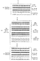
次に図2を参照して、光ディスクに記録されるトランスポートストリーム(TS)及びプログラムストリーム(PS)の構成について説明する。ここに、図2(a)は、比較のため、従来のDVDにおけるMPEG2のプログラムストリームの構成を図式的に示すものであり、図2(b)は、MPEG2のトランスポートストリーム(TS)の構成を図式的に示すものである。更に、図2(c)は、本発明におけるMPEG2のプログラムストリームの構成を図式的に示すものである。
【0027】
図2(a)において、従来のDVDに記録される一つのプログラムストリームは、時間軸tに沿って、主映像情報たるビデオデータ用のビデオストリームを1本だけ含み、更に、音声情報たるオーディオデータ用のオーディオストリームを最大で8本含み且つ副映像情報たるサブピクチャデータ用のサブピクチャストリームを最大で32本含んでなる。即ち、任意の時刻txにおいて多重化されるビデオデータは、1本のビデオストリームのみに係るものであり、例えば複数のテレビ番組或いは複数の映画などに対応する複数本のビデオストリームを同時にプログラムストリームに含ませることはできない。映像を伴うテレビ番組等を多重化して伝送或いは記録するためには、各々のテレビ番組等のために、少なくとも1本のビデオストリームが必要となるので、1本しかビデオストリームが存在しないDVDのプログラムストリーム形式では、複数のテレビ番組等を多重化して伝送或いは記録することはできないのである。
【0028】
図2(b)において、本発明の光ディスク100に記録される一つのトランスポートストリーム(TS)は、主映像情報たるビデオデータ用のエレメンタリーストリーム(ES)としてビデオストリームを複数本含んでなり、更に音声情報たるオーディオデータ用のエレメンタリーストリーム(ES)としてオーディオストリームを複数本含み且つ副映像情報たるサブピクチャデータ用のエレメンタリーストリーム(ES)としてサブピクチャストリームを複数本含んでなる。即ち、任意の時刻txにおいて多重化されるビデオデータは、複数本のビデオストリームに係るものであり、例えば複数のテレビ番組或いは複数の映画などに対応する複数のビデオストリームを同時にトランスポートストリームに含ませることが可能である。このように複数本のビデオストリームが存在するトランスポートストリーム形式では、複数のテレビ番組等を多重化して伝送或いは記録することが可能である。但し、現況のトランスポートストリームを採用するデジタル放送では、サブピクチャストリームについては伝送していない。
【0029】
図2(c)において、本発明の光ディスク100に記録される一つのプログラムストリーム(PS)は、主映像情報たるビデオデータ用のビデオストリームを複数本含んでなり、更に音声情報たるオーディオデータ用のオーディオストリームを複数本含み且つ副映像情報たるサブピクチャデータ用のサブピクチャストリームを複数本含んでなる。即ち、任意の時刻txにおいて多重化されるビデオデータは、複数本のビデオストリームに係るものであり、例えば複数のテレビ番組或いは複数の映画などに対応する複数のビデオストリームを同時にプログラムストリームに含ませることが可能である。
【0030】
尚、図2(a)から図2(c)では説明の便宜上、ビデオストリーム、オーディオストリーム及びサブピクチャストリームを、この順に上から配列しているが、この順番は、後述の如くパケット単位で多重化される際の順番等に対応するものではない。トランスポートストリームでは、概念的には、例えば一つの番組に対して、1本のビデオストリーム、2本の音声ストリーム及び2本のサブピクチャストリームからなる一まとまりが対応している。
【0031】
上述した本実施例の光ディスク100は、記録レートの制限内で、図2(b)に示した如きトランスポートストリーム(TS)を多重記録可能に、即ち複数の番組或いはプログラムを同時に記録可能に構成されている。更に、このようなトランスポートストリームに加えて又は代えて、同一光ディスク100上に、図2(c)に示した如きプログラムストリーム(PS)を多重記録可能に構成されている。
【0032】
次に図3から図10を参照して、光ディスク100上に記録されるデータの構造について説明する。ここに、図3は、光ディスク100上に記録されるデータ構造を模式的に示すものである。図4は、図3に示した各タイトル内におけるデータ構造の詳細を模式的に示すものである。図5及び図6は夫々、図3に示した各プレイ(P)リストセット内におけるデータ構造の詳細を模式的に示すものである。図7は、図6に示した各アイテムにおけるデータ構造の詳細を模式的に示すものである。図8は、図4に示した各タイトルエレメント内におけるデータの論理構成を模式的に示すものであり、図9は、各プレイリストセットをプレイリスト一つから構成する場合における、図4に示した各タイトルエレメント内におけるデータの論理構成を模式的に示すものである。図10は、図3に示した各オブジェクト内におけるデータ構造の詳細を模式的に示すものである。
【0033】
以下の説明において、「タイトル」とは、複数の「プレイリスト」を連続して実行する再生単位であり、例えば、映画1本、テレビ番組1本などの論理的に大きなまとまりを持った単位である。「プレイリストセット」とは、「プレイリスト」の束をいう。例えば、アングル再生やパレンタル再生における相互に切替可能な特定関係を有する複数のコンテンツ情報を再生するためのプレイリストの束や、同時間帯に放送され且つまとめて記録された複数番組に係るコンテンツ情報を再生するためのプレイリストの束である。或いは、同一タイトルについて、ハイビジョン対応、ディスプレイの解像度、サラウンドスピーカ対応、スピーカ配列など、情報再生システムにおいて要求される映像再生機能(ビデオパーフォーマンス)別や音声再生機能(オーディオパーフォーマンス)別など、要求機能別に用意された各種コンテンツ情報を再生するためのプレイリストの束である。「プレイリスト」とは、「オブジェクト」の再生に必要な情報を格納した情報であり、オブジェクトへアクセスするためのオブジェクトの再生範囲に関する情報が各々格納された複数の「アイテム」で構成されている。そして、「オブジェクト」とは、上述したMPEG2のトランスポートストリームを構成するコンテンツの実体情報である。
【0034】
図3において、光ディスク100は、論理的構造として、ディスク情報ファイル110、プレイ(P)リスト情報ファイル120、オブジェクト情報ファイル130及びオブジェクトデータファイル140の4種類のファイルを備えており、これらのファイルを管理するためのファイルシステム105を更に備えている。尚、図3は、光ディスク100上における物理的なデータ配置を直接示しているものではないが、図3に示す配列順序を、図1に示す配列順序に対応するように記録すること、即ち、ファイルシステム105等をリードインエリア104に続いてデータ記録エリア106に記録し、更にオブジェクトデータファイル140等をデータ記録エリア106に記録することも可能である。図1に示したリードインエリア104やリードアウトエリア108が存在せずとも、図3に示したファイル構造は構築可能である。
【0035】
ディスク情報ファイル110は、光ディスク100全体に関する総合的な情報を格納するファイルであり、ディスク総合情報112と、タイトル情報テーブル114と、その他の情報118とを格納する。ディスク総合情報112は、例えば光ディスク100内の総タイトル数等を格納する。タイトル情報テーブル114は、タイトルポインタ114−1と、これにより識別番号又は記録アドレスが示される複数のタイトル200(タイトル#1〜#m)を含んで構成されている。各タイトル200には、論理情報として、各タイトルのタイプ(例えば、シーケンシャル再生型、分岐型など)や、各タイトルを構成するプレイ(P)リスト番号をタイトル毎に格納する。
【0036】
図4に示すように各タイトル200は、より具体的には例えば、タイトル総合情報200−1と、複数のタイトルエレメント200−2と、その他の情報200−5とを含んで構成されている。更に、各タイトルエレメント200−2は、プリコマンド200PRと、プレイリストセットへのポインタ200PTと、ポストコマンド200PSと、その他の情報200−6とから構成されている。
【0037】
ポインタ200PTは、当該ポインタ200PTを含むタイトルエレメント200−2に基づいて再生されるべきコンテンツ情報に対応する、プレイリスト情報ファイル120内に格納されたプレイリストセット126Sの識別番号を示す。なお、ポインタ200PTは、タイトルエレメント200−2に基づいて再生されるべきコンテンツ情報に対応するプレイリストセット126Sの記録位置を示す情報であっても良い。プリコマンド200PRは、ポインタ200PTにより指定される一のプレイリストセット126Sにより再生シーケンスが規定されるコンテンツ情報の再生前に実行されるべきコマンドを示す。ポストコマンド200PSは、該一のプレイリストセットにより再生シーケンスが規定されるコンテンツ情報の再生後に実行されるべきコマンドを示す。タイトルエレメント200−2に含まれるその他の情報200−5は、例えば、タイトルエレメントに係る再生の次の再生に係るタイトルエレメントを指定するネクスト情報を含む。
【0038】
従って、後述する情報再生装置による当該情報記録媒体の再生時には、ポインタ200PTに従ってプレイリストセット126Sにアクセスして、それに含まれる複数のプレイリスト126のうち、所望の番組等に対応するものを選択するように制御を実行すれば、タイトルエレメント200−2として当該所望のコンテンツ情報を再生できる。更に、このようなタイトルエレメント200−2を一つ又は順次再生することで、一つのタイトル200を再生可能となる。更に、プリコマンド200PRに従って、ポインタ200PTで指定される一のプレイリストセット126Sにより再生シーケンスが規定されるコンテンツ情報の、再生前に実行されるべきコマンドを実行できる。更に、ポストコマンド200PSに従って、ポインタ200PTで指定される一のプレイリストセット126Sにより再生シーケンスが規定されるコンテンツ情報の、再生後に実行されるべきコマンドを実行できる。ポストコマンド200PSは、例えばコンテンツ情報の分岐を命令するコマンド、次のタイトルを選ぶコマンド等である。加えて、その他の情報200−5に含まれるネクスト情報に従って、当該再生中のタイトルエレメント200−2の次のタイトルエレメント200−2を再生できる。
【0039】
再び図3において、プレイリスト情報ファイル120は、プレイ(P)リストセット総合情報122と、プレイリストセット情報テーブル121と、複数のプレイ(P)リストセット126S(Pリストセット#1〜#n)と、その他の情報128とに分かれている。このプレイリストセット情報テーブル121には、プレイ(P)リストセットポインタ124と、プレイリストセット番号順に各プレイリストセット126S(Pリストセット#1〜#n)の論理情報を格納する。言い換えれば、各プレイリストセット126Sの格納順番がプレイリストセット番号である。また、上述したタイトル情報テーブル114で、同一のプレイリストセット126Sを、複数のタイトル200から参照することも可能である。即ち、タイトル#qとタイトル#rとが同じプレイリストセット#pを使用する場合にも、プレイリストセット情報テーブル121中のプレイリストセット#pを、タイトル情報テーブル114でポイントするように構成してもよい。
【0040】
図5に示すように、プレイリストセット126Sは、総合情報126−1と、複数のプレイリスト126(プレイリスト#1〜#x)と、アイテム定義テーブル126−3と、その他の情報126−4とを含んで構成されている。そして、各プレイリスト126は、複数のプレイリストエレメント126−2(プレイリストエレメント#1〜#y)と、その他の情報126−5とを含んで構成されている。更に、各プレイリストエレメント126−2は、プリコマンド126PRと、アイテムへのポインタ126PTと、ポストコマンド126PSと、その他の情報126−6とから構成されている。
【0041】
ポインタ126PTは、当該ポインタ126PTを含むプレイリストエレメント126−2に基づいて再生されるべきコンテンツ情報に対応する、アイテム定義テーブル126−3により定義されるアイテムの識別番号を示す。なお、ポインタ126PTは、アイテム定義テーブル126−3により定義されるアイテムの記録位置であっても良い。
【0042】
図6に例示したように、プレイリストセット126Sにおいて、アイテム定義テーブル126−3内には、複数のアイテム204が定義されている。これらは、複数のプレイリスト126によって共有されている。また、総合情報126−1として、当該プレイリストセット126S内に含まれる各プレイリスト126の名称、再生時間などのUI(ユーザインタフェース情報)、各アイテム定義テーブル126−3へのアドレス情報等が記述されている。
【0043】
再び図5において、本発明に係る第2プリコマンドの一例たるプリコマンド126PRは、ポインタ126PTにより指定される一のアイテム204の再生前に実行されるべきコマンドを示す。本発明に係る第2ポストコマンドの一例たるポストコマンド126PSは、該一のアイテム204の再生後に実行されるべきコマンドを示す。プレイリストエレメント126−2に含まれるその他の情報126−6は、例えば、プレイリストエレメント126−2に係る再生の次の再生に係るプレイリストエレメント126−2を指定するネクスト情報を含む。
【0044】
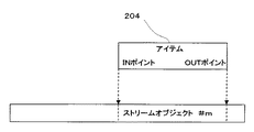
図7に例示したように、アイテム204は、表示の最小単位である。アイテム204には、オブジェクトの開始アドレスを示す「INポイント情報」及び終了アドレスを示す「OUTポイント情報」が記述されている。尚、これらの「INポイント情報」及び「OUTポイント情報」は夫々、直接アドレスを示してもよいし、再生時間軸上における時間或いは時刻など間接的にアドレスを示してもよい。図中、“ストリームオブジェクト#m”で示されたオブジェクトに対して複数のES(エレメンタリーストリーム)が多重化されている場合には、アイテム204の指定は、特定のESの組合せ或いは特定のESを指定することになる。
【0045】
図8に例示したように、タイトルエレメント200−2は、論理的に、プリコマンド200PR或いは126PRと、ポインタ200PTにより選択されるプレイリストセット126Sと、ポストコマンド200PS或いはポストコマンド126PSと、ネクスト情報200−6Nとから構成されている。従って、例えばビデオ解像度など、システムで再生可能な何らかの条件等に従って、プレイリストセット126S中からプレイリスト126を選択する処理が実行される。
【0046】
但し図9に例示したように、ポインタ200PTにより指定されるプレイリストセットが単一のプレイリストからなる場合には、即ち図3に示したプレイリストセット126Sを単一のプレイリスト126に置き換えた場合には、タイトルエレメント200−2は、論理的に、プリコマンド200PR或いは126PRと、再生時に再生されるプレイリスト126と、ポストコマンド200PS或いはポストコマンド126PSと、ネクスト情報200−6Nとから構成されてもよい。この場合には、システムで再生可能な条件等に拘わらず、プレイリストセットが再生用に指定されれば、単一のプレイリスト126の再生処理が実行されることになる。
【0047】
再び図3において、オブジェクト情報ファイル130は、各プレイリスト126内に構成される各アイテムに対するオブジェクトデータファイル140中の格納位置(即ち、再生対象の論理アドレス)や、そのアイテムの再生に関する各種属性情報が格納される。本実施例では特に、オブジェクト情報ファイル130は、後に詳述する複数のAU(アソシエートユニット)情報132I(AU#1〜AU#q)を含んでなるAUテーブル131と、ES(エレメンタリーストリーム)マップテーブル134と、その他の情報138とを格納する。
【0048】
オブジェクトデータファイル140は、トランスポートストリーム(TS)別のTSオブジェクト142(TS#1オブジェクト〜TS#sオブジェクト)、即ち実際に再生するコンテンツの実体データを、複数格納する。
【0049】
尚、図3を参照して説明した4種類のファイルは、更に夫々複数のファイルに分けて格納することも可能であり、これらを全てファイルシステム105により管理してもよい。例えば、オブジェクトデータファイル140を、オブジェクトデータファイル#1、オブジェクトデータファイル#2、…というように複数に分けることも可能である。
【0050】
図10に示すように、論理的に再生可能な単位である図3に示したTSオブジェクト142は、例えば6kB(Byte)のデータ量を夫々有する複数のアラインドユニット143に分割されてなる。アラインドユニット143の先頭は、TSオブジェクト142の先頭に一致(アラインド)されている。各アラインドユニット143は更に、192Bのデータ量を夫々有する複数のソースパケット144に細分化されている。ソースパケット144は、物理的に再生可能な単位であり、この単位即ちパケット単位で、光ディスク100上のデータのうち少なくともビデオデータ、オーディオデータ及びサブピクチャデータは多重化されており、その他の情報についても同様に多重化されてよい。各ソースパケット144は、4Bのデータ量を有する、再生時間軸上におけるTS(トランスポートストリーム)パケットの再生処理開始時刻を示すパケットアライバルタイムスタンプ等の再生を制御するための制御情報145と、188Bのデータ量を有するTSパケット146とを含んでなる。TSパケット146は、パケットヘッダ146aとTSパケットペイロード146bとを有し、TSパケットペイロード146bには、ビデオデータがパケット化されて「ビデオパケット」とされるか、オーディオデータがパケット化されて「オーディオパケット」とされるか、又はサブピクチャデータがパケット化されて「サブピクチャパケット」とされるか、若しくは、その他のデータがパケット化される。
【0051】
次に図11及び図12を参照して、図2(b)に示した如きトランスポートストリーム形式のビデオデータ、オーディオデータ、サブピクチャデータ等が、図10に示したTSパケット146により、光ディスク100上に多重記録される点について説明する。ここに、図11は、上段のプログラム#1(PG1)用のエレメンタリーストリーム(ES)と中段のプログラム#2(PG2)用のエレメンタリーストリーム(ES)とが多重化されて、これら2つのプログラム(PG1&2)用のトランスポートストリーム(TS)が構成される様子を、横軸を時間軸として概念的に示すものであり、図12は、一つのトランスポートストリーム(TS)内に多重化されたTSパケットのイメージを、時間の沿ったパケット配列として概念的に示すものである。
【0052】
図11に示すように、プログラム#1用のエレメンタリーストリーム(上段)は、例えば、プログラム#1用のビデオデータがパケット化されたTSパケット146が時間軸(横軸)に対して離散的に配列されてなる。プログラム#2用のエレメンタリーストリーム(中段)は、例えば、プログラム#2用のビデオデータがパケット化されたTSパケット146が時間軸(横軸)に対して離散的に配列されてなる。そして、これらのTSパケット146が多重化されて、これら二つのプログラム用のトランスポートストリーム(下段)が構築されている。尚、図11では説明の便宜上省略しているが、図2(b)に示したように、実際には、プログラム#1用のエレメンタリーストリームとして、オーディオデータがパケット化されたTSパケットからなるエレメンタリーストリームやサブピクチャデータがパケット化されたTSパケットからなるサブピクチャストリームが同様に多重化されてもよく、更にこれらに加えて、プログラム#2用のエレメンタリーストリームとして、オーディオデータがパケット化されたTSパケットからなるエレメンタリーストリームやサブピクチャデータがパケット化されたTSパケットからなるサブピクチャストリームが同様に多重化されてもよい。
【0053】
図12に示すように、本実施例では、このように多重化された多数のTSパケット146から、一つのTSストリームが構築される。そして、多数のTSパケット146は、このように多重化された形で、パケットアライバルタイムスタンプ等145の情報を付加し、光ディスク100上に多重記録される。尚、図12では、プログラム#i(i=1,2,3)を構成するデータからなるTSパケット146に対して、j(j=1,2,…)をプログラムを構成するストリーム別の順序を示す番号として、“Element(i0j)”で示しており、この(i0j)は、エレメンタリーストリーム別のTSパケット146の識別番号たるパケットIDとされている。このパケットIDは、複数のTSパケット146が同一時刻に多重化されても相互に区別可能なように、同一時刻に多重化される複数のTSパケット146間では固有の値が付与されている。
【0054】
また図12では、PAT(プログラムアソシエーションテーブル)及びPMT(プログラムマップテーブル)も、TSパケット146単位でパケット化され且つ多重化されている。これらのうちPATは、複数のPMTのパケットIDを示すテーブルを格納している。特にPATは、所定のパケットIDとして、図12のように(000)が付与されることがMPEG2規格で規定されている。即ち、同一時刻に多重化された多数のパケットのうち、パケットIDが(000)であるTSパケット146として、PATがパケット化されたTSパケット146が検出されるように構成されている。そして、PMTは、一又は複数のプログラムについて各プログラムを構成するエレメンタリーストリーム別のパケットIDを示すテーブルを格納している。PMTには、任意のパケットIDを付与可能であるが、それらのパケットIDは、上述の如くパケットIDが(000)として検出可能なPATにより示されている。従って、同一時刻に多重化された多数のパケットのうち、PMTがパケット化されたTSパケット146(即ち、図12でパケットID(100)、(200)、(300)が付与されたTSパケット146)が、PATにより検出されるように構成されている。
【0055】
図12に示した如きトランスポートストリームがデジタル伝送されて来た場合、チューナは、このように構成されたPAT及びPMTを参照することにより、多重化されたパケットの中から所望のエレメンタリーストリームに対応するものを抜き出して、その復調が可能となるのである。
【0056】
そして、本実施例では、図10に示したTSオブジェクト142内に格納されるTSパケット146として、このようなPATやPMTのパケットを含む。即ち、図12に示した如きトランスポートストリームが伝送されてきた際に、そのまま光ディスク100上に記録できるという大きな利点が得られる。
【0057】
更に、本実施例では、このように記録されたPATやPMTについては光ディスク100の再生時には参照することなく、代わりに図3に示した後に詳述するAUテーブル131及びESマップテーブル134を参照することによって、より効率的な再生を可能とし、複雑なマルチビジョン再生等にも対処可能とする。このために本実施例では、例えば復調時や記録時にPAT及びPMTを参照することで得られるエレメンタリーストリームとパケットとの対応関係を、AUテーブル131及びESマップテーブル134の形で且つパケット化或いは多重化しないで、オブジェクト情報ファイル130内に格納するのである。
【0058】
次に図13を参照して、光ディスク100上のデータの論理構成について説明する。ここに、図13は、光ディスク100上のデータの論理構成を、論理階層からオブジェト階層或いは実体階層への展開を中心に模式的に示したものである。
【0059】
図13において、光ディスク100には、例えば映画1本、テレビ番組1本などの論理的に大きなまとまりであるタイトル200が、一又は複数記録されている。各タイトル200は、一又は複数のタイトルエレメント200−2を含む。各タイトルエレメント200−2は、複数のプレイリストセット126Sから論理的に構成されている。各タイトルエレメント200−2内で、複数のプレイリストセット126Sはシーケンシャル構造を有してもよいし、分岐構造を有してもよい。
【0060】
尚、単純な論理構成の場合、一つのタイトルエレメント200は、一つのプレイリストセット126Sから構成され、更に一つのプレイリストセット126Sは、一つのプレイリスト126から構成される。また、一つのプレイリストセット126Sを複数のタイトルエレメント200−2或いは、複数のタイトル200から参照することも可能である。
【0061】
各プレイリスト126は、複数のアイテム(プレイアイテム)204から論理的に構成されている。各プレイリスト126内で、複数のアイテム204は、シーケンシャル構造を有してもよいし、分岐構造を有してもよい。また、一つのアイテム204を複数のプレイリスト126から参照することも可能である。アイテム204に記述された前述のINポイント情報及びOUTポイント情報により、TSオブジェクト142の再生範囲が論理的に指定される。そして、論理的に指定された再生範囲についてオブジェクト情報130dを参照することにより、最終的にはファイルシステムを介して、TSオブジェクト142の再生範囲が物理的に指定される。ここに、オブジェクト情報130dは、TSオブジェクト142の属性情報、TSオブジェクト142内におけるデータサーチに必要なESアドレス情報134d等のTSオブジェクト142を再生するための各種情報を含む(尚、図3に示したESマップテーブル134は、このようなESアドレス情報134dを複数含んでなる)。
【0062】
そして、後述の情報再生装置によるTSオブジェクト142の再生時には、アイテム204及びオブジェクト情報130dから、当該TSオブジェクト142における再生すべき物理的なアドレスが取得され、所望のエレメンタリーストリームの再生が実行される。
【0063】
このように本実施例では、アイテム204に記述されたINポイント情報及びOUTポイント情報並びにオブジェクト情報130dのESマップテーブル134(図3参照)内に記述されたESアドレス情報134dにより、再生シーケンスにおける論理階層からオブジェクト階層への関連付けが実行され、エレメンタリーストリームの再生が可能とされる。
【0064】
以上詳述したように本実施例では、光ディスク100上においてTSパケット146の単位で多重記録されており、これにより、図2(b)に示したような多数のエレメンタリーストリームを含んでなる、トランスポートストリームを光ディスク100上に多重記録可能とされている。本実施例によれば、デジタル放送を光ディスク100に記録する場合、記録レートの制限内で複数の番組或いは複数のプログラムを同時に記録可能であるが、ここでは一つのTSオブジェクト142へ複数の番組或いは複数のプログラムを多重化して記録する方法を採用している。
【0065】
(サブピクチャデータの構造及び制御)
次に図14から図16を参照して、サブピクチャデータの構造及び制御について説明する。ここに、図14は、サブピクチャデータを制御するためのSPコントロール情報のデータ構成(図14(a))及びサブピクチャデータの本体をなす静止画データたるSPデータを含んでなるSPデータ構造(図14(b))の一具体例を示す概念図である。また、図15は、これらのSPコントロール情報及びSPデータ構造から構成される三種類のサブピクチャ構造を図式的に示したものである。図16は、SPD用ストリームと複数のSCP用ストリームとの関係を、再生時間軸に対して図式的に示したものである。
【0066】
本実施例では、後述するサブピクチャデコーダによりデコードされたサブピクチャデータは、バッファとして機能するメモリに一時的に記憶される。その後、この一時的に記憶されたサブピクチャデータに含まれるSPデータ(静止画データ)及びSPコントロール情報(静止画コントロールデータ)の少なくとも一方は、システムコントローラからの制御信号Sc5による制御を受けて読み出される。そして、係るSPデータに対して、SPコントロール情報を作用させることで、ビデオ出力の一部或いは全部として静止画表示が行われる。
【0067】
図14(a)に示すように、SPコントロール情報721は、SCPヘッダと、SFコントロールパラメータとを有する。「SCPヘッダ」は、当該SPコントロール情報721が制御対象とするSPデータを特定するSPデータ識別子、係るSPデータの記録位置を示す情報等からなる。「SFコントロールパラメータ」は、SPデータにより規定される画像のうち少なくとも一部として切り取られる画像部分であるサブフレーム(SF)の単位で、SPデータを制御するための各種パラメータからなる。より具体的には、SFデータの表示開始時刻や表示終了時刻をPTS(プレゼンテーションタイムスタンプ)等で示すパラメータを有し、更に例えば、表示時間、サブピクチャの切り出し範囲や表示する際の配置、拡大縮小、回転等の条件等を示す各種パラメータを有する。
【0068】
図14(b)に示すように、SPデータ構造722は、構造情報とSPデータ(静止画データの実体)とを有する。「構造情報」は、当該SPデータを識別するための識別子、当該SPデータの長さ等の情報からなる。「SPデータ」は、例えばランレングスエンコーディングされたビットマップデータ形式或いはJPEG形式の画像データ等を有する。
【0069】
よって、サブピクチャデータの再生時には、図14(b)に示したSPデータの少なくとも一部が切り出されたサブフレームの単位で、図14(a)に示したSFコントロールパラメータに基づいて、サブフレームを用いた各種再生制御が実行される。
【0070】
図15に示すように、SPコントロール情報721及びSPデータ構造722は、複数のTSパケット146(図10参照)にパケット化されて多重化されている。そして、サブピクチャ構造におけるSPコントロール情報721の先頭部分が格納されるTSパケット146を、“SCP”と呼び、サブピクチャ構造におけるSPデータ構造722の先頭部分が格納されるTSパケット146を、“SPD”と呼ぶ。
【0071】
図15(a)に示すように、SCPを含むSPコントロール情報721及びSPデータ構造722は、一つのサブピクチャ構造とされて、複数のTSパケット146に分断されてもよい。図15(b)に示すように、SCPを含むSPコントロール情報721は、一つのサブピクチャ構造とされて、複数のTSパケット146に分断されてもよい。図15(c)に示すように、SPDを含むSPデータ情報構造722は、一つのサブピクチャ構造とされて、複数のTSパケット146に分断されてもよい。
【0072】
本実施例では、例えば、SPD用ストリーム上に記録されたSPデータ構造722内のSPデータに対して、このストリームとは別のSCP用ストリーム上に記録されたSPコントロール情報721を作用させることで、静止画の再生制御を行う。この場合、一つのSPD用ストリームに対して作用するSCP用ストリームは、ひとつだけ存在してもよいし、複数存在してもよい。これらの二種類のストリームを、相互に異なるエレメンタリーストリーム上に記録することで、効率的な再生制御が可能となる。更に、一つのSPD用ストリーム上のSPデータに対して、複数のSCP用ストリーム上の複数のSPコントロール情報を作用させることで、一層効率的な再生制御が可能となる。
【0073】
より具体的には図16に示すように、“ES_PID=200”のビデオストリーム(Video1)が再生されている途中における時刻t11で、“ES_PID=201”のSPD用ストリーム上のSPデータ(SPD1)の読み込みが開始されて、後述する情報再生装置のメモリに格納される。そして、格納されたSPデータは、例えば、設定された終了時間まで格納され続けるか、或いは次のサブピクチャの読み込みが開始されるまで格納され続ける。
【0074】
図16では、“ES_PID=202”のSCP用ストリーム(SCP1)には、時刻t21、時刻t22、時刻t23及び時刻t24のタイミングで夫々、SCP♯1a、SCP♯1b、SCP♯1c及びSCP♯1dが配置されている。“ES_PID=203”のSCP用ストリーム(SCP2)には、時刻t31、時刻t32及び時刻t33のタイミングで夫々SCP♯2a、SCP♯2b及びSCP♯2cが配置されている。“ES−PID=204”のSCP用ストリーム(SCP3)には、時刻t41、時刻t42、時刻t43及び時刻t44のタイミングで夫々SCP♯3a、SCP♯3b、SCP♯3c及びSCP♯3dが配置されている。
【0075】
但し、このような静止画の再生制御に加えて、サブピクチャストリーム上に記録されたサブピクチャデータ構造内のSPデータに対して、同じストリーム上に記録されたサブピクチャ構造内のSPコントロール情報を作用させて、静止画の再生制御を行っても構わない。即ち、一つのサブピクチャストリームのみに、SPコントロール情報721及びSPデータ構造722の両者を記録して、SPコントロール情報721をSPデータ構造722に作用させてもよい。
【0076】
いずれの場合にも、データ量の多いビットマップテータやJPEGデータからなるSPデータの使い回しによって、ディスク上における限られた記録容量の節約を図ることが可能となり、更に効率的な再生及び表示処理も可能となる。加えて、いずれの場合にも、他のビデオストリームに記録されたビデオデータに基づく動画或いは主映像上に、このようなサブピクチャをスーパーインポーズさせることも可能である。
【0077】
(オブジェクト情報ファイル)
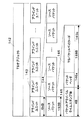
次に、図17を参照して、オブジェクト情報ファイル130について一具体例を挙げて詳細に説明する。ここに図17は、オブジェクト情報ファイル130内に構築されるAU(アソシエートユニット)テーブル131(図3参照)及びこれに関連付けられるES(エレメンタリーストリーム)マップテーブル134(図3参照)におけるデータ構成の一具体例を図式的に示すものである。
【0078】
図17に示すように本具体例では、オブジェクト情報ファイル130内には、オブジェクト情報テーブル(オブジェクト情報table)が格納されている。そして、このオブジェクト情報テーブルは、図中上段に示すAUテーブル131及び下段に示すESマップテーブル134から構成されている。
【0079】
図17の上段において、AUテーブル131は、各フィールド(Field)が必要な個数分のテーブルを追加可能な構造を有してもよい。例えば、AUが4つ存在すれば、該当フォールドが4つに増える構造を有してもよい。
【0080】
AUテーブル131には、別フィールド(Field)に、AUの数、各AUへのポインタなどが記述される「AUテーブル総合情報」と、「その他の情報」とが格納されている。
【0081】
そして、AUテーブル131内には、各AU#nに対応する各PU#mにおけるESテーブルインデックス#S(ES_table Index #S)を示すAU情報132Iとして、対応するESマップテーブル134のインデックス番号(Index番号=…)が記述されている。ここで「AU」とは、前述の如く例えばテレビ放送でいうところの“番組”に相当する単位(特に、“マルチビジョン型”の放送の場合には、切り替え可能な複数の“ビジョン”を一まとめとした単位)であり、この中に再生単位であるPUが一つ以上含まれている。また、「PU」とは、前述の如く各AU内に含まれる相互に切り替え可能なエレメンタリーストリームの集合であり、PU情報302Iにより各PUに対応するESテーブルインデックス#Sが特定されている。例えば、AUでマルチビューコンテンツを構成する場合、AU内には、複数のPUが格納されていて、夫々のPU内には、各ビューのコンテンツを構成するパケットを示す複数のエレメンタリーストリームパケットIDへのポインタが格納されている。これは後述するESマップテーブル134内のインデックス番号を示している。
【0082】
図17の下段において、ESマップテーブル134には、フィールド(Field)別に、ESマップテーブル総合情報と、複数のインデックス#m(m=1,2,…)と、「その他の情報」とが格納されている。
【0083】
「ESマップテーブル総合情報」には、当該ESマップテーブルのサイズや、総インデックス数等が記述される。
【0084】
そして「インデックス#S」は夫々、再生に使用される全エレメンタリーストリームのエレメンタリーストリームパケットID(ES_PID)と、それに対応するインデックス番号及びエレメンタリーストリームのアドレス情報を含んで構成されている。
【0085】
本実施例では例えば、このアドレス情報、即ちESアドレス情報134dとして、前述のようにエレメンタリーストリームがMPEG2のビデオストリームである場合には、Iピクチャの先頭のTSパケット番号とこれに対応する表示時間のみが、ESマップテーブル134中に記述されており、データ量の削減が図られている。
【0086】
このように構成されているため、AUテーブル131から指定されたESマップテーブル134のインデックス番号から、実際のエレメンタリーストリームのエレメンタリーストリームパケットID(ES_PID)が取得可能となる。また、そのエレメンタリーストリームパケットIDに対応するエレメンタリーストリームのアドレス情報も同時に取得可能であるため、これらの情報を元にしてオブジェクトデータの再生が可能となる。
【0087】
以上説明した光ディスク100のデータ構造によれば、もし新しいタイトルを光ディスク100に追加する場合でも、簡単に必要な情報を追加できるので有益である。逆に、例えば編集等を行った結果、ある情報が不要になったとしても、単にその情報を参照しなければよいだけであり、実際にその情報をテーブルから削除しなくてもよい構造となっているため有益である。
【0088】
尚、図17では、上段のAUテーブル131から参照しないES_PIDについても、下段のESマップテーブル134のインデックス別に記述してあるが、当該参照しないES_PIDについては、このように記述する必要はない。但し、このように参照しないES_PIDをも記述することで、より汎用性の高いESマップテーブル134を作成しておけば、例えば、オーサリングをやり直す場合など、コンテンツを再編集する場合にESマップテーブルを再構築する必要がなくなるという利点がある。
【0089】
(再生時のアクセスの流れ)
次に図18を参照して、本実施例における特徴の一つであるAU(アソシエートユニット)情報132及びPU(プレゼンテーションユニット)情報302を用いた情報再生装置における再生時のアクセスの流れについて、光ディスク100の論理構造と共に説明する。ここに図18は、光ディスク100の論理構造との関係で、再生時におけるアクセスの流れ全体を概念的に示すものである。
【0090】
図18において、光ディスク100の論理構造は、論理階層401、オブジェクト階層403及びこれら両階層を相互に関連付ける論理−オブジェクト関連付け階層402という三つの階層に大別される。
【0091】
これらのうち論理階層401は、再生時に所望のタイトルを再生するための各種論理情報と再生すべきプレイリスト(Pリスト)及びその構成内容とを論理的に特定する階層である。論理階層401には、光ディスク100上の全タイトル200等を示すディスク情報110dが、ディスク情報ファイル110(図3参照)内に記述されており、更に、光ディスク100上の全コンテンツの再生シーケンス情報120dが、プレイリスト情報ファイル120(図3参照)内に記述されている。より具体的には、再生シーケンス情報120dとして、各タイトル200に含まれる一又は複数のタイトルエレメント200−2に対して夫々、一又は複数のプレイリストセット126Sの構成が記述されている。更に、各プレイリストセット126Sは、一又は複数のプレイリスト126を含んでおり、各プレイリスト126には、一又は複数のアイテム204(図13参照)の構成が記述されている。そして、再生時におけるアクセスの際に、このような論理階層401によって、再生すべきタイトル200を特定し、これに対応するプレイリスト126を特定し、更にこれに対応するアイテム204を特定する。
【0092】
続いて、論理−オブジェクト関連付け階層402は、このように論理階層401で特定された情報に基づいて、実体データであるTSオブジェクトデータ140dの組み合わせや構成の特定を行うと共に論理階層401からオブジェクト階層403へのアドレス変換を行うように、再生すべきTSオブジェクトデータ140dの属性とその物理的な格納アドレスとを特定する階層である。より具体的には、論理−オブジェクト関連付け階層402には、各アイテム204を構成するコンテンツの固まりをAU132という単位に分類し且つ各AU132をPU302という単位に細分類するオブジェクト情報データ130dが、オブジェクト情報ファイル130(図3参照)に記述されている。
【0093】
ここで、「PU(プレゼンテーションユニット)302」とは、複数のエレメンタリーストリームを、再生切り替え単位ごとに関連付けてまとめた単位である。仮に、このPU302中にオーディオストリームが3本存在すれば、このビジョンを再生中には、ユーザが自由に3本のオーディオ(例えば、言語別オーディオなど)を切り替えることが可能となる。
【0094】
他方、「AU(アソシエートユニット)132」とは、一つのタイトルで使用するTSオブジェクト中の、ビデオストリームなどのエレメンタリーストリームを複数まとめた単位であり、一又は複数のPU302の集合からなる。より具体的には、PU302を介して間接的に、エレメンタリーストリームパケットID(ES_PID)を各TSオブジェクト毎にまとめた単位である。このAU132は、例えば多元放送における相互に切り替え可能な複数の番組或いは複数のプログラムなど、コンテンツから考えて相互に特定関係を有する複数の番組或いは複数のプログラムなどの集合に対応している。そして、同一のAU132に属したPU302は、再生時にユーザ操作により相互に切り替え可能な複数の番組或いは複数のプログラムを夫々構成する一又は複数のエレメンタリーストリームの集合に対応している。
【0095】
従って、再生すべきAU132が特定され、更にそれに属するPU302が特定されれば、再生すべきエレメンタリーストリームが特定される。即ち、図12に示したPATやPMTを用いないでも、光ディスク100から多重記録された中から所望のエレメンタリーストリームを再生可能となる。
【0096】
ここで実際に再生されるエレメンタリーストリームは、PU情報302から、エレメンタリーストリームのパケットID(図12参照)であるES_PIDによって特定或いは指定される。同時に、再生の開始時間及び終了時間を示す情報が、エレメンタリーストリームのアドレス情報に変換されることにより、特定エレメンタリーストリームの特定領域(或いは特定時間範囲)におけるコンテンツが再生されることになる。
【0097】
このようにして論理−オブジェクト関連付け階層402では、各アイテム204に係る論理アドレスから各PU302に係る物理アドレスへのアドレス変換が実行される。
【0098】
続いて、オブジェクト階層403は、実際のTSオブジェクトデータ140dを再生するための物理的な階層である。オブジェクト階層403には、TSオブジェクトデータ140dが、オブジェクトデータファイル140(図3参照)内に記述されている。より具体的には、複数のエレメンタリーストリーム(ES)を構成するTSパケット146が時刻毎に多重化されており、これらが時間軸に沿って配列されることにより、複数のエレメンタリーストリームが構成されている(図11参照)。そして、各時刻で多重化された複数のTSパケットは、エレメンタリーストリーム毎に、論理−オブジェクト関連付け階層402で特定されるPU302に対応付けられている。尚、複数のPU302と、一つのエレメンタリーストリームとを関連付けること(例えば、切り替え可能な複数の番組間或いは複数のプログラム間で、同一のオーディオデータに係るエレメンタリーストリームを共通で利用したり、同一のサブピクチャデータに係るエレメンタリーストリームを共通で利用すること)も可能である。
【0099】
このようにオブジェクト階層403では、論理−オブジェクト関連付け階層402における変換により得られた物理アドレスを用いての、実際のオブジェクトデータの再生が実行される。
【0100】
以上のように図18に示した三つの階層により、光ディスク100に対する再生時におけるアクセスが実行される。
【0101】
[情報再生装置]
次に、上述の光ディスク100から情報を再生するのに好適な情報再生装置について説明する。図19に情報再生装置の構成を示す。図示のように、情報再生装置は、光ディスク100から情報を再生する装置であり、大別して光ピックアップ501と、ECCユニット502と、発振器503と、アライバルタイムクロックカウンタ504と、システムコントローラ520と、再生系700と、再生系800とを有する。
【0102】
光ピックアップ501は、光ディスク100に対してレーザービームなどの光ビームを所定の情報読取用パワーで照射するとともに、光ディスク100の情報記録面からの反射光を受光して、読取信号を生成してECCユニット502へ供給する。なお、再生時には、光ディスク100はスピンドルモータにより回転制御される。そして、図示しないサーボユニットはシステムコントローラ520から供給されるサーボ制御信号に基づいて、スピンドルモータによる光ディスク100の回転を制御するスピンドルサーボ、光ピックアップ502のフォーカスサーボ及びトラッキングサーボなどの各種サーボ制御を実行する。
【0103】
光ピックアップ501により生成された読取信号はECCユニット502へ送られる。この読取信号はパケット化された複数のエレメンタリーストリーム(PES:Packetized Elementary Stream)を分割し多重化したトランスポートストリームであり、ECCユニット502はソースパケット144(図10参照)を信号Psとして再生系700及び再生系800へ供給する。
【0104】
再生系700は、光ディスク100上に記録されたエレメンタリーストリームのうち、プライベートストリーム(PS:Private Stream)2方式に従うエレメンタリーストリームをデコードし再生する系である。これに対し、再生系800は、プライベートストリーム2以外の方式に従うエレメンタリーストリームをデコードし再生する系である。
【0105】
上述した例によれば、光ディスク100上に記録されているエレメンタリーストリームのうち、ビデオストリーム、オーディオストリーム、サブピクチャーデータストリーム、及びシステムストリームは、プライベートストリーム2以外の方式である。これに対し、サブピクチャの表示を制御するためのコントロールデータを含むサブピクチャコントロールデータストリーム、及びコントロールデータストリームはプライベートストリーム2の方式である。従って、ビデオストリーム、オーディオストリーム及びサブピクチャーデータストリーム、PAT、PMTは再生系800で再生されるのに対し、サブピクチャコントロールデータストリーム及びコントロールデータストリームなどは再生系700で再生されることになる。
【0106】
図示のように、再生系800は、トラックバッファ805と、ソースデパケッタイザ810と、デマルチプレクサ820と、トランスポートバッファ821〜824と、メインバッファ831〜834と、ビデオデコーダ841と、サブピクチャデコーダ842と、オーディオデコーダ843と、システム制御デコーダ844とを備える。ECCユニット502から出力されたソースパケット144は、まずトラックバッファ805に一旦格納された後、ソースデパケッタイザ810へ送られる。トラックバッファ805は、光ディスク100への記録データを再生することにより得られるソースパケットを格納するためのバッファである。なお、トラックバッファ805が一杯でないときはECCユニット502からトラックバッファ805へ所定のデータ伝送レートでソースパケットが供給されるが、トラックバッファ805が一杯であるときはソースパケットの伝送は行われない。また、トラックバッファ805は常にアンダーフローしないように制御される。
【0107】
ソースデパケッタイザ810は、ソースパケット144から、パケットアライバルタイムスタンプ(以下、「ATS」とも呼ぶ。)などを含む制御情報145を取り出し、そのATSにより示されるタイミングで、そのソースパケット144に含まれるTSパケット146を信号Ptsとしてデマルチプレクサ820へ供給する。
【0108】
より詳細に説明すると、まず、発振器503は所定周波数のクロックパルスを生成し、アライバルタイムクロックカウンタ504は発振器503が生成するクロックパルスをカウントすることにより、アライバルタイムクロックATCKをソースデパケッタイザ810へ供給する。ソースデパケッタイザ810は、アライバルタイムクロックカウンタ504から入力されるアライバルタイムクロックATCKに基づいて、ソースパケット144から取得したATSが示すタイミングで、当該ソースパケット144に含まれているTSパケット146をデマルチプレクサ820へ供給する。こうして、プライベートストリーム2方式以外のエレメンタリーストリーム、即ち、ビデオストリーム、オーディオストリーム、サブピクチャストリーム、及びシステムストリームのTSパケット146がデマルチプレクサ820へ入力される。
【0109】
なお、ソースデパケッタイザ810は、少なくとも1つのソースパケット分の容量を有する内部バッファを備えており、その内部バッファを利用して時間軸補正を行う。その内部バッファが空になるとすぐに、トラックバッファ805からソースデパケッタイザ810へTSパケット146が送られる。
【0110】
デマルチプレクサ820は、各エレメンタリーストリームの種類及び符号化方法に従って、ソースデパケッタイザ810から入力されたTSパケット146を選別し、それぞれのデコード処理系へ供給する。即ち、デマルチプレクサ820は、ビデオストリームのTSパケット146をトランスポートバッファ821へ供給し、サブピクチャストリームのTSパケット146をトランスポートバッファ822へ供給し、オーディオストリームのTSパケット146をトランスポートバッファ823へ供給し、システムストリームのTSパケット146をトランスポートバッファ824へ供給する。
【0111】
トランスポートバッファ821は、ビデオストリームのTSパケット146を受け取ると、パケットヘッダ146aを除去してビデオデータを抽出してメインバッファ831へ送る。メインバッファ831は所定量(例えばデコード処理を行う単位データ量)のビデオデータを格納してビデオデコーダ841へ送る。ビデオデコーダ841は、ビデオデータをデコードし、ビデオ信号として出力する。このビデオ信号はモニタなどに送られ表示される。
【0112】
サブピクチャストリーム、オーディオストリーム及びシステムストリームについても、同様にデコード処理がなされる。即ち、サブピクチャストリームのTSパケット146はトランスポートバッファ822、メインバッファ832及びサブピクチャデコーダ842によりサブピクチャとして出力され、サブピクチャコントロールストリームによって制御される。オーディオストリームのTSパケット146はトランスポートバッファ823、メインバッファ833及びオーディオデコーダ843によりオーディオ出力される。また、システムストリームのTSパケット146は、トランスポートバッファ824、メインバッファ834及びシステム制御デコーダ844により制御情報として出力される。
【0113】
プライベートストリーム2以外のMPEG準拠のエレメンタリーストリームは、パケット化されたエレメンタリーストリームをデコードすべき時間を示すデコード時間情報であるPTS(Presentation Time Stamp)/DTS(Decode TimeStamp)を含む。なお、ビデオデータやオーディオデータなどのPESパケットがデコードされるタイミングと、それらが表示/再生されるタイミングとが同一である場合はPTSのみが含まれ、異なる場合にはPTS及びDTSの両方が含まれる。よって、各デコーダ841〜844は、それぞれのストリームのTSパケットペイロード146b複数からなるPESパケットを、PTS/DTSに示されるタイミングでデコードし、再生/表示する。
【0114】
このように、再生系800は、主としてビデオストリーム、サブピクチャストリーム、オーディオストリームなどのコンテンツのストリームであって、プライベートストリーム2方式以外の方式のソースパケットをデコードし、再生する。
【0115】
一方、再生系700は、ソースデパケッタイザ710と、デマルチプレクサ720と、トランスポートバッファ731及び732と、メインバッファ741及び742と、デコーダ751及び752とを備える。ソースデパケッタイザ710は、ECCユニット502からソースパケット144を受け取り、図10に示す制御情報145を除去してTSパケット146を取り出す。この制御情報145にはATSが含まれるが、ソースデパケッタイザ710はこのATSを無視し、そのソースパケットに含まれるTSパケット146を直ちにデマルチプレクサ720へ供給する。
【0116】
デマルチプレクサ720は、各エレメンタリーストリーム、即ち、サブピクチャコントロールデータストリーム及びコントロールデータストリームの種類や符号化方法に応じて、それぞれのTSパケットを選別し、サブピクチャコントロールデータストリームのTSパケット146をトランスポートバッファ731へ送り、コントロールデータストリームのTSパケット146をトランスポートバッファ732へ送る。トランスポートバッファ731はサブピクチャコントロールデータストリームのTSパケット146を受け取り、パケットヘッダ146aを除去してサブピクチャコントロールデータをメインバッファ741へ送る。メインバッファ741は、所定量毎にサブピクチャコントロールデータをデコーダ751へ送り、デコーダ751はデコードしたサブピクチャコントロールデータをシステムコントローラ520へ送る。システムコントローラ520は、前述のように、サブピクチャコントロールデータを用いて、サブピクチャデータの再生を制御する。同様に、コントロールデータストリームのTSパケットはトランスポートバッファ732、メインバッファ742及びデコーダ752により処理され、システムコントローラ520へ送られる。
【0117】
このように、本発明の情報再生装置では、ビデオ、オーディオ、サブピクチャなどのコンテンツを再生するための再生制御情報がトランスポートストリーム中のエレメンタリーストリームに含まれる場合に、それら再生制御情報のエレメンタリーストリームを含むソースパケットと、コンテンツのエレメンタリーストリームを含むソースパケットとを別の再生系で処理する。より具体的には、再生制御情報を含むエレメンタリーストリーム及びコンテンツを含むエレメンタリーストリームの両方を再生系700及び800の2系統にそれぞれ供給する。そして、再生系700では、再生制御情報を含むソースパケットのみをデマルチプレクサ720において抽出し、遅延なくデコード処理及び再生処理を行う。これにより、再生制御情報の取得が迅速に行われ、コンテンツの再生に遅れが生じることを防止することができる。一方、再生系800では、コンテンツを含むソースパケットのみを、トラックバッファ805を介してソースデパケッタイザ810がデマルチプレクサ820に送り、各コンテンツをデコード及び再生する。このように、トランスポートストリーム中に含まれる各種エレメンタリーストリームのパケットのうち、コンテンツを含むパケットについてはトラックバッファを用いて時間軸方向の制御を行って正しくコンテンツデータをデコードするとともに、再生制御情報を含むパケットについてはトラックバッファを通さず、ATSを無視することにより迅速にデコードを行って、再生制御情報の取得に遅れが生じないようにしている。
【0118】
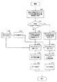
次に、本発明の情報再生装置による再生処理の流れを説明する。図20は、本発明の情報再生装置による再生処理のフローチャートである。なお、この処理の開始時には、ユーザの指定などにより、再生されるべきタイトルが特定されているものとする。また、各ソースパケット144がプライベートストリーム2方式のソースパケットであるか否かは、各エレメンタリーストリーム毎に予め決定されている。本実施例では、前述のように、サブピクチャコントロールデータストリーム及びコントロールデータストリームのソースパケットはプライベートストリーム2方式で構成されており、ビデオストリーム、サブピクチャストリーム、オーディオストリーム及びシステムストリームのソースパケットはプライベートストリーム2方式以外の方式で構成されている。各エレメンタリーストリームがプライベートストリーム2方式に対応するか否かを示す情報は、各エレメンタリーストリームの属性情報中に含まれている。システムコントローラ520は予めこの情報を取得しており、各エレメンタルストリームがプライベートストリーム2方式であるか否かを既に認識している。また、再生すべきオブジェクト情報としての各ソースパケット144は、図19に示すように光ディスク100から光ピックアップ501及びECCユニット502を介して再生系700のデマルチプレクサ720及び再生系800のデマルチプレクサ820にそれぞれ入力されている。
【0119】
図20を参照すると、まず、システムコントローラ520は、先に図18を参照して説明したように、再生すべきタイトルに従って順に光ディスク100から読み出されるエレメンタリーストリームの全てのPID情報(ES_PID)及び属性情報を論理情報から取得する(ステップS700)。次に、システムコントローラ520は、取得したPID情報が、プライベートストリーム2方式のソースパケットであるか否かを判定する(ステップS701)。そして、システムコントローラ520は、プライベートストリーム2のPID情報とそれ以外のPID情報をそれぞれ別々に内部メモリなどにストックする(ステップS704及びS714)。
【0120】
そして、システムコントローラ520は、信号Dpidにより(図19参照)、プライベートストリーム2方式以外の方式のソースパケットのPID情報を再生系800のデマルチプレクサ820へ供給するとともに(ステップS705)、プライベートストリーム2方式のソースパケットのPID情報を再生系700のデマルチプレクサ720へ供給する(ステップS715)。この処理により、再生系700のデマルチプレクサ720は、プライベートストリーム2方式のTSパケット、つまり、サブピクチャコントロールデータストリーム及びコントロールデータストリームのTSパケットを取得し、それ以外のエレメンタリーストリームのTSパケットを破棄するように設定される。同様に、再生系800のデマルチプレクサ820は、プライベートストリーム2方式以外の方式のTSパケット、つまり、ビデオストリーム、サブピクチャストリーム、オーディオストリーム及びシステムストリームのTSパケットを取得し、それら以外のエレメンタリーストリームのTSパケットを破棄するように設定される。
【0121】
ここで、再生系800のデマルチプレクサ820へは前述のように再生に必要な全てのソースパケット144中のTSパケット146がソースデパケッタイザ810を介して送られている(ステップS702)。一方、再生系700では、ソースデパケッタイザ710は各ソースパケット144中のATSを無視して(ステップS703)、直ちにTSソースパケット146をソースデパケッタイザ710を介してデマルチプレクサ720へ送る。
【0122】
再生系800のデマルチプレクサ820は、プライベートストリーム2方式のソースパケットを全て破棄し(ステップS706)、それ以外の方式のソースパケットのみを取得して、デコード処理を行う(ステップS707)。なお、デコード処理は上述のように、各デコーダ841〜844において、各エレメンタリーストリームの種類毎に行われる。一方、再生系700のデマルチプレクサ720は、プライベートストリーム2方式の以外の方式のソースパケットを全て破棄し(ステップS716)、プライベートストリーム2方式のソースパケットのみを取得してデコード処理を行う(ステップS717)。
【0123】
こうして、再生すべきタイトルに含まれるソースパケットが光ディスク100から読み出され、再生系700により再生制御情報のみが抽出されてデコードされるとともに、再生系800によりコンテンツ情報が抽出されてデコードされる。サブピクチャコントロールデータストリーム及びコントロールデータストリームなどの再生制御情報は、再生系700により迅速に処理されるので、再生制御情報のデコード処理の遅延のためにコンテンツ自体の再生に遅れが生じるという不具合を防止することができる。
【図面の簡単な説明】
【図1】本発明の情報記録媒体の一実施例である光ディスクの基本構造を示し、上側部分は複数のエリアを有する光ディスクの概略平面図であり、これに対応付けられる下側部分は、その径方向におけるエリア構造の図式的概念図である。
【図2】従来のMPEG2のプログラムストリームの図式的概念図(図2(a))、本実施例で利用されるMPEG2のトランスポートストリームの図式的概念図(図2(b))であり、本実施例で利用されるMPEG2のプログラムストリームの図式的概念図(図2(c))である。
【図3】本実施例の光ディスク上に記録されるデータ構造の模式的に示す図である。
【図4】図3に示した各タイトル内におけるデータ構造の詳細を階層的に示す概念図である。
【図5】図3に示した各プレイリストセット内におけるデータ構造の詳細を階層的に示す概念図である。
【図6】図3に示した各プレイリストセット内におけるデータ構造の詳細を模式的に示す概念図である。
【図7】図6に示した各アイテムにおけるデータ構造の詳細を模式的に示す概念図である。
【図8】図4に示した各タイトルエレメント内におけるデータの論理構成を模式的に示す概念図である。
【図9】本実施例において、各プレイリストセットをプレイリスト一つから構成する場合における、図4に示した各タイトルエレメント内におけるデータの論理構成を模式的に示す概念図である。
【図10】図3に示した各オブジェクト内におけるデータ構造の詳細を模式的に示す概念図である。
【図11】本実施例における、上段のプログラム#1用のエレメンタリーストリームと中段のプログラム#2用のエレメンタリーストリームとが多重化されて、これら2つのプログラム用のトランスポートストリームが構成される様子を、横軸を時間軸として概念的に示す図である。
【図12】本実施例における、一つのトランスポートストリーム内に多重化されたTSパケットのイメージを、時間の沿ったパケット配列として概念的に示す概念図である。
【図13】実施例における光ディスク上のデータの論理構成を、論理階層からオブジェト階層或いは実体階層への展開を中心に模式的に示した図である。
【図14】サブピクチャデータを制御するためのSPコントロール情報のデータ構成、及び、サブピクチャデータの本体をなす静止画データたるSPデータを含んでなるSPデータ構造の一具体例を示す概念図である。
【図15】SPコントロール情報及びSPデータ構造から構成される三種類のサブピクチャ構造を図式的に示した図である。
【図16】SPD用ストリームと複数のSCP用ストリームとの関係を、再生時間軸に対して図式的に示したものである。
【図17】本実施例による一具体例における、オブジェクト情報ファイル内に構築されるAUテーブル及びこれに関連付けられるESマップテーブルにおけるデータ構成の一具体例を図式的に示す図である。
【図18】本実施例における、光ディスクの論理構造との関係で、再生時におけるアクセスの流れ全体を概念的に示す図である。
【図19】本発明の実施例に係る情報再生装置の概略構成を示すブロック図である。
【図20】本発明の実施例に係る情報再生装置による情報再生処理のフローチャートである。
【符号の説明】
100 光ディスク
105 ファイルシステム
110 ディスク情報ファイル
120 プレイリスト情報ファイル
126 プレイリスト
130 オブジェクト情報ファイル
134 ESマップテーブル
140 オブジェクトデータファイル
142 TS(トランスポートストリーム)オブジェクト
146 TSパケット
200 タイトル
204 アイテム
502 ECC
520 システムコントローラ
710、810 ソースパケッタイザ
700、800 再生系
720、820 デマルチプレクサ
805 トラックバッファ[0001]
TECHNICAL FIELD OF THE INVENTION
The present invention relates to an information reproducing apparatus and method for reproducing information from an information recording medium such as a high-density optical disk on which various information such as main video, audio, sub-video, and reproduction control information are recorded at high density, and an information reproducing program. Belongs to the technical field.
[0002]
[Prior art]
DVDs have been commonly used as optical disks on which various information such as main video, audio, sub-video, and reproduction control information are recorded. According to the DVD standard, main video information (video data), audio information (audio data), and sub-video information (sub-picture data) are each packetized together with playback control information (navigation data), and a high-efficiency encoding technique is used. Are multiplex-recorded on a disc in a program stream (Program Stream) format of the MPEG2 (Moving Picture Experts Group Group 2) standard. In the main video information, data compressed according to the MPEG video format (ISO 13818-2) exists in one program stream for one stream. On the other hand, audio information is recorded by a plurality of methods (that is, linear PCM, AC-3, MPEG audio, etc.), and up to a total of eight streams can exist in one program stream. The sub-picture information is defined by a bitmap and recorded by compression in a run-length system, and up to 32 streams can exist in one program stream.
[0003]
A DVD player that plays such a DVD is configured to decode recorded data in a program stream format via a buffer memory called a track buffer. The track buffer is originally used to prevent video data and audio data to be played from underflowing and maintain seamless playback, for example, during track jump, angle playback, and parental playback. Have been. For this reason, the program stream data read from the DVD is temporarily stored in a track buffer, except for a part of the information, and then read at a predetermined timing, and is decoded by various decoders such as a video decoder and an audio decoder. You. Thus, the video data and the audio data are reproduced seamlessly (without interruption).
[0004]
On the other hand, the transport stream (Transport @ Stream) format of the MPEG2 standard has been standardized, which is suitable for data transmission. According to this transport stream format, a plurality of elementary streams are transmitted simultaneously. For example, a plurality of programs or programs, such as a large number of satellite digital broadcast television channels, are multiplexed in a time-division manner and transmitted simultaneously on one satellite wave. Therefore, the digital satellite broadcast receiver is configured to be able to process such transport stream data.
[0005]
[Problems to be solved by the invention]
In such an environment, for example, it is conceivable that data in a transport stream format such as digital satellite broadcast data is recorded on an optical disc such as a DVD and reproduced by a player or the like.
[0006]
The transport stream data of the MPEG2 standard includes an elementary stream for controlling display and reproduction of the content itself, in addition to data of the content itself such as video data and audio data. Therefore, when the transport stream format data recorded on an optical disk such as a DVD is reproduced by the above-described player or the like, not only the elementary stream of the content itself such as video and audio but also the above-described elementary stream for reproduction control is reproduced. After being temporarily stored in the track buffer, it is read and decoded.
[0007]
However, if decoding processing is performed after passing through a track buffer to an elementary stream for playback control, it takes more time than necessary to acquire playback control information, and as a result, content such as video and audio is required. In some cases, there is a problem that a delay occurs in the display / reproduction control of the device itself. Furthermore, when elementary streams for playback control exist for each control target, it is necessary to quickly and quickly identify the playback control information and input the information to a decoder. In the case of DVD-Video, in order to prevent this, only the DSI information is reproduced without passing through the track buffer, but it is not possible to cope with a case where a plurality of similar information exists. The problems to be solved by the present invention include, for example, those described above.
[0008]
The present invention provides display / playback control of content itself from a recording medium in which not only the content itself such as video and audio, but also their playback control data are recorded as elementary streams in a transport stream format. It is an object of the present invention to provide an information reproducing apparatus and method capable of displaying / reproducing information without delay, and an information reproducing program.
[0009]
[Means for Solving the Problems]
According to the first aspect of the present invention, an entire stream obtained by multiplexing a first partial stream group forming a content body and a second partial stream group for controlling reproduction of the content body is a predetermined stream. An information reproducing apparatus for reproducing information from an information recording medium recorded in packet units, comprising: reproducing means for reproducing the entire stream recorded on the recording medium; and reproducing data output from the reproducing means. And a first demultiplexer that receives the read data read from the track buffer memory and selects and outputs a packet corresponding to the first partial stream group; A first group of decoders connected to an output of a multiplexer, and reproduction data output from the reproduction means; Characterized in that it comprises a second demultiplexer for selecting and outputting a packet corresponding to stream group, and a second decoder group connected to an output of the second demultiplexer.
[0010]
According to a fifth aspect of the present invention, an entire stream formed by multiplexing a first partial stream group forming a content main body and a second partial stream group for controlling reproduction of the content main body is a predetermined stream. An information reproducing method for reproducing information from an information recording medium recorded in packet units, comprising: a reproducing step of reproducing the entire stream recorded on the recording medium; and a reproducing data output from the reproducing means. Accumulating in a track buffer memory, a first demultiplexing step of inputting reproduction data read from the track buffer memory and selectively outputting a packet corresponding to the first partial stream group, A first decoding step of decoding the output of the first demultiplexer; and inputting the reproduced data output from the reproducing means. A second demultiplexing step of selecting and outputting a packet corresponding to the second partial stream group; and a second decoding step of decoding an output of the second demultiplexer. I do.
[0011]
The invention according to
[0012]
BEST MODE FOR CARRYING OUT THE INVENTION
In a preferred embodiment of the present invention, an entire stream formed by multiplexing a first partial stream group forming a content main body and a second partial stream group for controlling reproduction of the content main body is a predetermined stream. An information reproducing apparatus for reproducing information from an information recording medium recorded in packet units is provided. The information reproducing apparatus includes: a reproducing unit that reproduces the entire stream recorded on the recording medium; a track buffer memory that stores reproduction data output from the reproducing unit; and a reproduction buffer that is read from the track buffer memory. A first demultiplexer for inputting data and selectively outputting a packet corresponding to the first partial stream group, a first decoder group connected to an output of the first demultiplexer, A second demultiplexer that receives the output reproduced data and selects and outputs a packet corresponding to the second partial stream group, a second decoder group connected to an output of the second demultiplexer, It comprises.
[0013]
In this embodiment, for example, the content itself such as video and audio is configured as a first partial stream group in the form of stream data, and information for controlling the reproduction of the content itself is similarly stored in the form of stream data. To form a second partial stream group. Then, an entire stream in which the first partial stream group and the second partial stream group are multiplexed is configured, and the entire stream is recorded on the information recording medium in a predetermined packet unit.
[0014]
In the information reproducing apparatus for reproducing information from the information recording medium, the reproducing means reproduces the entire stream from the recording medium and supplies reproduced data to two processing systems. The first processing system is a processing system for processing the first partial stream data, and includes a track buffer memory, a first demultiplexer, and a first decoder group. The second processing system is a processing system for processing the second partial stream data, and includes a second demultiplexer and a second decoder group.
[0015]
In the first processing system, the reproduction data output from the reproduction means is stored in the track buffer memory. Then, the first demultiplexer selectively outputs only the packet corresponding to the first partial stream from the reproduction data of the entire stream output from the track buffer memory to the first decoder group. Therefore, the first demultiplexer discards the packet corresponding to the second partial stream included in the entire stream. Then, the first decoder group decodes and outputs data of the content itself such as video data and audio data.
[0016]
On the other hand, the second processing system does not have a track buffer, and the reproduction data corresponding to the entire stream output from the reproduction means is sent to the second demultiplexer. The second demultiplexer selects and outputs only packets corresponding to the second partial stream from the reproduced data of the entire stream to the second decoder group, and the packets of each stream are input to the corresponding decoder. . Therefore, the second demultiplexer discards the packet corresponding to the first partial stream included in the entire stream. Even when there are a plurality of second partial streams, each stream is decoded and output by the corresponding decoder without any problem.
[0017]
According to the above configuration, the same data corresponding to the entire stream is sent to the first and second processing systems, and only the packets corresponding to the necessary partial streams are extracted and the processing is executed. The first partial stream constituting the content itself needs to be decoded and adjusted for the playback time using a track buffer or the like and output, while the second partial stream such as control data is playback control information. Need to obtain information without delay. Therefore, the second partial stream is decoded by the second processing system having no track buffer. As a result, it is possible to avoid a situation in which it takes time to acquire the reproduction control information recorded in the form of stream data and delays in reproducing the content body.
[0018]
In a preferred aspect, the first partial stream group includes a video stream, an audio stream, and a sub-picture stream, and the second partial stream group includes a sub-picture control data stream controlling the sub-picture stream; And a control data stream for controlling the content body. In this case, the first decoder group includes a video decoder that decodes the data of the video stream output from the first demultiplexer, and an audio decoder that decodes the data of the audio stream output from the first demultiplexer. , A sub-picture decoder that decodes a sub-picture stream output from the first demultiplexer, and a second group of decoders includes data of the sub-picture control data stream output from the second demultiplexer. And a control data decoder for decoding the data of the control data stream output from the second demultiplexer.
[0019]
In another preferred aspect, the packet corresponding to the partial stream group includes output timing information indicating a timing at which data in the packet is to be output to the demultiplexer, and the information reproducing apparatus stores the data in the track buffer memory. A first depacketizer that acquires a packet corresponding to the first partial stream group from the reproduced data that has been input, and inputs the reproduced data in the packet to a first demultiplexer in accordance with output timing information included in the packet; Acquiring a packet corresponding to the second partial stream group from the reproduction data output from the reproduction means, and immediately converting the reproduction data in the packet to the second demultiplexer regardless of the output timing information included in the packet. And a second depacketizer for inputting the data to a second packetizer. According to this aspect, the first partial stream forming the content body is input to the demultiplexer at an appropriate timing according to the output timing information. On the other hand, the second partial stream, which is the reproduction control information, can promptly proceed with the decoding process regardless of the output timing information.
[0020]
That is, the second depacketizer can immediately input the reproduction data in the packet to the second demultiplexer upon acquiring the packet corresponding to the second partial stream group, thereby delaying the decoding of the reproduction control information. Can be run without.
[0021]
Further, in another embodiment of the present invention, an entire stream obtained by multiplexing a first partial stream group forming a content main body and a second partial stream group for controlling display of the content main body is: An information reproducing method for reproducing information from an information recording medium recorded in a predetermined packet unit can be provided. The method includes: a reproducing step of reproducing the entire stream recorded on the recording medium; an accumulating step of accumulating reproduction data output from the reproducing means in a track buffer memory; A first demultiplexing step of inputting reproduction data and selectively outputting a packet corresponding to the first partial stream group, a first decoding step of decoding an output of the first demultiplexer, A second demultiplexing step of inputting the reproduced data output from the means and selectively outputting a packet corresponding to the second partial stream group, and a second decoding step of decoding an output of the second demultiplexer And a step. According to this information reproducing method, similarly to the above-described information reproducing apparatus, it is possible to reproduce the content main body without delay from an information recording medium in which both the content main body and its reproduction control information are recorded in the form of stream data. is there.
[0022]
Further, in still another embodiment of the present invention, the program is executed on a computer, thereby causing the computer to execute a first partial stream group forming a content body and a second partial stream group for controlling display of the content body. It is possible to provide an information reproducing program that functions as an information reproducing apparatus that reproduces information from an information recording medium in which an entire stream obtained by multiplexing a partial stream group is recorded in predetermined packet units. The information reproducing apparatus includes: a reproducing unit that reproduces the entire stream recorded on the recording medium; a track buffer memory that stores reproduction data output from the reproducing unit; and a reproduction buffer that is read from the track buffer memory. A first demultiplexer for inputting data and selectively outputting a packet corresponding to the first partial stream group, a first decoder group connected to an output of the first demultiplexer, A second demultiplexer that receives the output reproduced data and selects and outputs a packet corresponding to the second partial stream group, a second decoder group connected to an output of the second demultiplexer, Is provided. By executing this information reproducing program on a computer, the information reproducing apparatus described above can be realized. That is, if this information reproduction program is used, the content main body can be reproduced without delay from an information recording medium in which both the content main body and its reproduction control information are recorded in the form of stream data.
[0023]
【Example】
[Information recording medium]
An information recording medium reproduced by the information reproducing apparatus of the present invention will be described with reference to FIGS. The information recording medium described below is an example of a type of an optical disc capable of recording (writing) and reproducing (reading).
[0024]
(Basic structure)
First, the basic structure of the optical disk of the present embodiment will be described with reference to FIG. FIG. 1 is a schematic plan view showing the structure of an optical disk having a plurality of areas on the upper side, and the area structure in the radial direction is shown on the lower side in association with a conceptual diagram.
[0025]
As shown in FIG. 1, the
[0026]
Next, the configuration of the transport stream (TS) and the program stream (PS) recorded on the optical disc will be described with reference to FIG. Here, FIG. 2A schematically shows the structure of an MPEG2 program stream in a conventional DVD for comparison, and FIG. 2B shows the structure of an MPEG2 transport stream (TS). Is shown schematically. FIG. 2C schematically shows the structure of an MPEG2 program stream according to the present invention.
[0027]
In FIG. 2A, one program stream recorded on a conventional DVD includes only one video stream for video data as main video information along with a time axis t, and further includes audio data as audio information. And up to 32 sub-picture streams for sub-picture data as sub-picture information. That is, video data multiplexed at an arbitrary time tx relates to only one video stream. For example, a plurality of video streams corresponding to a plurality of television programs or a plurality of movies are simultaneously converted into a program stream. It cannot be included. In order to multiplex and transmit or record television programs accompanied by video, at least one video stream is required for each television program. Therefore, a DVD program having only one video stream is required. In the stream format, a plurality of television programs cannot be multiplexed for transmission or recording.
[0028]
In FIG. 2B, one transport stream (TS) recorded on the
[0029]
In FIG. 2C, one program stream (PS) recorded on the
[0030]
2 (a) to 2 (c), the video stream, the audio stream, and the sub-picture stream are arranged from the top in this order for convenience of description, but this order is multiplexed in packet units as described later. It does not correspond to the order in which they are converted. In the transport stream, for example, a group of one video stream, two audio streams, and two sub-picture streams conceptually corresponds to, for example, one program.
[0031]
The
[0032]
Next, the structure of data recorded on the
[0033]
In the following description, a “title” is a playback unit that continuously executes a plurality of “playlists”, and is a logically large unit such as one movie or one television program. is there. “Playlist set” refers to a bundle of “playlists”. For example, a bunch of playlists for reproducing a plurality of pieces of content information having a specific relationship that can be mutually switched in angle reproduction and parental reproduction, and contents related to a plurality of programs broadcast and recorded together in the same time zone This is a bunch of playlists for reproducing information. Alternatively, for the same title, there is a requirement for different video reproduction functions (video performance) and different audio reproduction functions (audio performance) required in the information reproduction system, such as HDTV, display resolution, surround speaker support, and speaker arrangement. This is a bundle of playlists for reproducing various types of content information prepared for each function. The “playlist” is information that stores information necessary for reproducing the “object”, and includes a plurality of “items” each of which stores information on a reproduction range of the object for accessing the object. . The “object” is the entity information of the content making up the above-described MPEG2 transport stream.
[0034]
In FIG. 3, the
[0035]
The
[0036]
As shown in FIG. 4, more specifically, each
[0037]
The pointer 200PT indicates the identification number of the playlist set 126S stored in the playlist information file 120 corresponding to the content information to be reproduced based on the title element 200-2 including the pointer 200PT.Note that the pointer 200PT may be information indicating the recording position of the playlist set 126S corresponding to the content information to be reproduced based on the title element 200-2.The pre-command 200PR indicates a command to be executed before the reproduction of the content information whose reproduction sequence is defined by one playlist set 126S specified by the pointer 200PT. The post command 200PS indicates a command to be executed after the reproduction of the content information whose reproduction sequence is defined by the one playlist set. The other information 200-5 included in the title element 200-2 includes, for example, next information for specifying a title element related to the next playback after the playback related to the title element.
[0038]
Therefore, at the time of reproducing the information recording medium by the information reproducing apparatus described later, the playlist set 126S is accessed according to the pointer 200PT, and a playlist corresponding to a desired program or the like is selected from the plurality of
[0039]
Referring again to FIG. 3, the play list information file 120 includes play (P) list set
[0040]
As shown in FIG. 5, the playlist set 126S includes general information 126-1, a plurality of playlists 126 (
[0041]
The pointer 126PT indicates an identification number of an item defined by the item definition table 126-3 corresponding to content information to be reproduced based on the playlist element 126-2 including the pointer 126PT.The pointer 126PT may be a recording position of an item defined by the item definition table 126-3.
[0042]
As illustrated in FIG. 6, in the playlist set 126S, a plurality of
[0043]
Referring again to FIG. 5, a precommand 126PR, which is an example of the second precommand according to the present invention, indicates a command to be executed before the reproduction of one
[0044]
As illustrated in FIG. 7, the
[0045]
As illustrated in FIG. 8, the title element 200-2 logically includes a precommand 200PR or 126PR,By pointer 200PTIt is composed of a selected playlist set 126S, a post command 200PS or a post command 126PS, and next information 200-6N. Therefore, the process of selecting the
[0046]
However, as illustrated in FIG.Designated by pointer 200PTIf the playlist set consists of a single playlist, that is, if the playlist set 126S shown in FIG. 3 is replaced with a
[0047]
In FIG. 3 again, the object information file 130 includes a storage position (that is, a logical address to be reproduced) in the object data file 140 for each item configured in each
[0048]
The object data file 140 stores a plurality of TS objects 142 (
[0049]
Note that the four types of files described with reference to FIG. 3 can be further divided into a plurality of files and stored, respectively, and all of them may be managed by the
[0050]
As shown in FIG. 10, the TS object 142 shown in FIG. 3, which is a logically reproducible unit, is divided into a plurality of aligned
[0051]
Next, with reference to FIGS. 11 and 12, video data, audio data, sub-picture data, etc. in the transport stream format as shown in FIG. 2B are transmitted to the
[0052]
As shown in FIG. 11, the elementary stream for program # 1 (upper part) is, for example, a
[0053]
As shown in FIG. 12, in the present embodiment, one TS stream is constructed from a large number of multiplexed
[0054]
In FIG. 12, a PAT (program association table) and a PMT (program map table) are also packetized and multiplexed in units of
[0055]
When a transport stream as shown in FIG. 12 is transmitted digitally, the tuner refers to the PAT and PMT configured as described above to convert a multiplexed packet into a desired elementary stream. The corresponding thing can be extracted and demodulated.
[0056]
In the present embodiment, such a PAT or PMT packet is included as the
[0057]
Further, in the present embodiment, the PAT or PMT recorded in this manner is not referred to when the
[0058]
Next, the logical configuration of data on the
[0059]
In FIG. 13, one or a plurality of logically
[0060]
In the case of a simple logical configuration, one
[0061]
Each
[0062]
Then, when the information reproducing apparatus described later reproduces the
[0063]
As described above, in the present embodiment, the logic in the playback sequence is based on the IN point information and the OUT point information described in the
[0064]
As described in detail above, in the present embodiment, multiplexed recording is performed on the
[0065]
(Structure and control of sub-picture data)
Next, the structure and control of the sub-picture data will be described with reference to FIGS. Here, FIG. 14 shows a data structure of SP control information for controlling sub-picture data (FIG. 14 (a)) and an SP data structure including SP data as still image data constituting the main body of the sub-picture data ( FIG. 15B is a conceptual diagram illustrating a specific example of FIG. FIG. 15 schematically shows three types of sub-picture structures composed of the SP control information and the SP data structure. FIG. 16 schematically shows the relationship between the SPD stream and a plurality of SCP streams with respect to the reproduction time axis.
[0066]
In the present embodiment, sub-picture data decoded by a sub-picture decoder described later is temporarily stored in a memory functioning as a buffer. Thereafter, at least one of the SP data (still image data) and the SP control information (still image control data) included in the temporarily stored sub-picture data is read out under the control of the control signal Sc5 from the system controller. It is. By applying the SP control information to the SP data, a still image is displayed as part or all of the video output.
[0067]
As shown in FIG. 14A, the SP control information 721 has an SCP header and SF control parameters. The “SCP header” includes an SP data identifier for specifying SP data to be controlled by the SP control information 721, information indicating a recording position of the SP data, and the like. The “SF control parameter” includes various parameters for controlling the SP data in units of subframes (SF), which are image parts cut out as at least a part of the image defined by the SP data. More specifically, it has parameters indicating the display start time and the display end time of SF data by PTS (presentation time stamp) and the like. It has various parameters indicating conditions such as reduction and rotation.
[0068]
As shown in FIG. 14B, the SP data structure 722 has structure information and SP data (substance of still image data). The “structure information” includes information such as an identifier for identifying the SP data and the length of the SP data. The “SP data” has, for example, run-length-encoded bitmap data format or JPEG format image data.
[0069]
Therefore, at the time of reproduction of the sub-picture data, the sub-frame is obtained based on the SF control parameter shown in FIG. 14A in units of the sub-frame in which at least a part of the SP data shown in FIG. The various reproduction controls using are performed.
[0070]
As shown in FIG. 15, the SP control information 721 and the SP data structure 722 are packetized and multiplexed into a plurality of TS packets 146 (see FIG. 10). The
[0071]
As shown in FIG. 15A, the SP control information 721 including the SCP and the SP data structure 722 may be divided into a plurality of
[0072]
In the present embodiment, for example, SP control information 721 recorded on an SCP stream different from this stream is applied to SP data in the SP data structure 722 recorded on the SPD stream. , And controls playback of a still image. In this case, there may be only one SCP stream acting on one SPD stream, or a plurality of SCP streams. By recording these two types of streams on different elementary streams, efficient playback control becomes possible. Further, by applying a plurality of pieces of SP control information on a plurality of SCP streams to SP data on one SPD stream, more efficient reproduction control can be performed.
[0073]
More specifically, as shown in FIG. 16, at time t11 while the video stream (Video1) of “ES_PID = 200” is being reproduced, SP data (SPD1) on the SPD stream of “ES_PID = 201” Is read and stored in the memory of the information reproducing apparatus described later. Then, the stored SP data continues to be stored, for example, until a set end time, or until the reading of the next sub-picture is started.
[0074]
In FIG. 16, the SCP stream (SCP1) of “ES_PID = 202” includes
[0075]
However, in addition to such playback control of a still image, the SP control information in the sub-picture structure recorded on the same stream is also used for the SP data in the sub-picture data structure recorded on the sub-picture stream. The control of the reproduction of the still image may be performed by applying the function. That is, both the SP control information 721 and the SP data structure 722 may be recorded only in one sub-picture stream, and the SP control information 721 may act on the SP data structure 722.
[0076]
In either case, by using bitmap data having a large data amount or reusing SP data including JPEG data, it is possible to save a limited recording capacity on the disc, and to achieve more efficient reproduction and display processing. Is also possible. In addition, in any case, such a sub-picture can be superimposed on a moving image or a main image based on video data recorded in another video stream.
[0077]
(Object information file)
Next, the object information file 130 will be described in detail with reference to FIG. FIG. 17 shows the data configuration of the AU (association unit) table 131 (see FIG. 3) constructed in the object information file 130 and the ES (elementary stream) map table 134 (see FIG. 3) associated therewith. Fig. 3 schematically shows one specific example.
[0078]
As shown in FIG. 17, in this specific example, the object information file 130 stores an object information table (object information table). The object information table includes an AU table 131 shown in the upper part of the figure and an ES map table 134 shown in the lower part.
[0079]
In the upper part of FIG. 17, the AU table 131 may have a structure capable of adding as many tables as required for each field. For example, if there are four AUs, the structure may be such that the number of folds increases to four.
[0080]
The AU table 131 stores “AU table comprehensive information” in which the number of AUs, a pointer to each AU, and the like are described, and “other information” in separate fields (Field).
[0081]
In the AU table 131, as AU information 132I indicating the ES table index #S (ES_table @ Index @ # S) in each PU # m corresponding to each AU # n, the index number (Index) of the corresponding ES map table 134 No. = ...) is described. Here, “AU” is a unit corresponding to a “program” in, for example, a television broadcast as described above (especially, in the case of a “multi-vision” broadcast, a plurality of switchable “visions” is one unit). A unit is a unit), and includes one or more PUs as playback units. Further, “PU” is a set of mutually switchable elementary streams included in each AU as described above, and the ES table index #S corresponding to each PU is specified by the PU information 302I. For example, when a multi-view content is configured by an AU, a plurality of PUs are stored in the AU, and a plurality of elementary stream packet IDs indicating packets forming the content of each view are stored in each PU. The pointer to is stored. This indicates an index number in the ES map table 134 described later.
[0082]
In the lower part of FIG. 17, the ES map table 134 stores ES map table general information, a plurality of indexes #m (m = 1, 2,...), And “other information” for each field (Field). Have been.
[0083]
The “ES map table comprehensive information” describes the size of the ES map table, the total number of indexes, and the like.
[0084]
The “index #S” is configured to include an elementary stream packet ID (ES_PID) of all elementary streams used for reproduction, an index number corresponding to the elementary stream packet ID, and address information of the elementary stream.
[0085]
In this embodiment, for example, as described above, when the elementary stream is an MPEG2 video stream as described above, the TS packet number at the head of the I picture and the display time corresponding thereto are used as the
[0086]
With this configuration, the elementary stream packet ID (ES_PID) of the actual elementary stream can be obtained from the index number of the ES map table 134 specified from the AU table 131. In addition, since the address information of the elementary stream corresponding to the elementary stream packet ID can be obtained at the same time, the object data can be reproduced based on the information.
[0087]
According to the data structure of the
[0088]
In FIG. 17, the ES_PID not referred to from the upper AU table 131 is also described for each index of the lower ES map table 134, but the ES_PID not referred to need not be described in this manner. However, if the ES map table 134 having higher versatility is created by describing the ES_PID that is not referred to in this way, the ES map table 134 is used when the content is re-edited, for example, when authoring is performed again. There is the advantage that there is no need to rebuild.
[0089]
(Access flow during playback)
Next, with reference to FIG. 18, the flow of access at the time of reproduction in an information reproducing apparatus using AU (association unit)
[0090]
In FIG. 18, the logical structure of the
[0091]
Among these, the
[0092]
Subsequently, based on the information specified in the
[0093]
Here, the “PU (presentation unit) 302” is a unit in which a plurality of elementary streams are associated with each other in units of playback switching. If there are three audio streams in the
[0094]
On the other hand, an “AU (association unit) 132” is a unit in which a plurality of elementary streams such as a video stream in a TS object used in one title are collected, and is composed of a set of one or a plurality of
[0095]
Therefore, if the
[0096]
Here, the elementary stream that is actually reproduced is specified or specified from the
[0097]
In this way, in the logical-
[0098]
Subsequently, the
[0099]
As described above, in the
[0100]
As described above, the access to the
[0101]
[Information playback device]
Next, an information reproducing apparatus suitable for reproducing information from the
[0102]
The
[0103]
The read signal generated by the
[0104]
The reproduction system 700 is a system that decodes and reproduces an elementary stream according to a private stream (PS: Private @ Stream) 2 method among the elementary streams recorded on the
[0105]
According to the above-described example, among the elementary streams recorded on the
[0106]
As shown, the reproduction system 800 includes a
[0107]
The source depacketizer 810 extracts control
[0108]
More specifically, first, the
[0109]
The source depacketizer 810 includes an internal buffer having a capacity for at least one source packet, and performs time axis correction using the internal buffer. As soon as its internal buffer becomes empty, a
[0110]
The demultiplexer 820 selects the
[0111]
Upon receiving the
[0112]
The decoding process is similarly performed on the sub-picture stream, the audio stream, and the system stream. That is, the
[0113]
The MPEG-compliant elementary stream other than the
[0114]
As described above, the playback system 800 decodes and plays back source packets that are mainly streams of content such as a video stream, a sub-picture stream, and an audio stream, and are in a format other than the
[0115]
On the other hand, the reproduction system 700 includes a
[0116]
The
[0117]
As described above, in the information reproducing apparatus of the present invention, when the reproduction control information for reproducing the content such as video, audio, and sub-picture is included in the elementary stream in the transport stream, the element of the reproduction control information is included. A source packet including a mental stream and a source packet including an elementary stream of content are processed by different reproduction systems. More specifically, both the elementary stream including the playback control information and the elementary stream including the content are supplied to the two systems of the playback systems 700 and 800, respectively. Then, in the reproduction system 700, only the source packet including the reproduction control information is extracted by the
[0118]
Next, a flow of a reproducing process by the information reproducing apparatus of the present invention will be described. FIG. 20 is a flowchart of a reproducing process by the information reproducing apparatus of the present invention. At the start of this processing, it is assumed that the title to be reproduced is specified by the user's specification or the like. Whether or not each
[0119]
Referring to FIG. 20, first, as described above with reference to FIG. 18, the system controller 520 sets all PID information (ES_PID) and attributes of the elementary streams read from the
[0120]
Then, the system controller 520 supplies the PID information of the source packet of a system other than the
[0121]
Here, as described above, the
[0122]
The demultiplexer 820 of the reproduction system 800 discards all source packets of the
[0123]
In this way, the source packet included in the title to be reproduced is read from the
[Brief description of the drawings]
FIG. 1 shows a basic structure of an optical disc which is an embodiment of an information recording medium of the present invention, wherein an upper part is a schematic plan view of an optical disc having a plurality of areas, FIG. 3 is a schematic conceptual diagram of an area structure in a radial direction.
FIG. 2 is a schematic conceptual diagram of a conventional MPEG2 program stream (FIG. 2A), and a schematic conceptual diagram of an MPEG2 transport stream used in the present embodiment (FIG. 2B); FIG. 2 is a schematic conceptual diagram (FIG. 2C) of an MPEG2 program stream used in the present embodiment.
FIG. 3 is a diagram schematically showing a data structure recorded on the optical disc of the embodiment.
FIG. 4 is a conceptual diagram hierarchically showing details of a data structure in each title shown in FIG. 3;
FIG. 5 is a conceptual diagram hierarchically showing details of a data structure in each playlist set shown in FIG. 3;
FIG. 6 is a conceptual diagram schematically showing details of a data structure in each playlist set shown in FIG. 3;
FIG. 7 is a conceptual diagram schematically showing details of a data structure of each item shown in FIG. 6;
FIG. 8 is a conceptual diagram schematically showing a logical configuration of data in each title element shown in FIG.
9 is a conceptual diagram schematically showing a logical configuration of data in each title element shown in FIG. 4 when each playlist set is composed of one playlist in the present embodiment.
FIG. 10 is a conceptual diagram schematically showing details of a data structure in each object shown in FIG. 3;
FIG. 11 is a diagram illustrating an example in which the elementary stream for the
FIG. 12 is a conceptual diagram conceptually showing an image of TS packets multiplexed in one transport stream as a packet arrangement along time in this embodiment.
FIG. 13 is a diagram schematically illustrating a logical configuration of data on an optical disc in the embodiment, focusing on development from a logical hierarchy to an object hierarchy or a real hierarchy.
FIG. 14 is a conceptual diagram showing a specific example of a data structure of SP control information for controlling sub-picture data, and an SP data structure including SP data as still image data which is the main body of the sub-picture data is there.
FIG. 15 is a diagram schematically showing three types of sub-picture structures composed of SP control information and an SP data structure.
FIG. 16 schematically shows a relationship between an SPD stream and a plurality of SCP streams with respect to a reproduction time axis.
FIG. 17 is a diagram schematically illustrating a specific example of a data configuration in an AU table constructed in an object information file and an ES map table associated therewith in a specific example according to the embodiment;
FIG. 18 is a diagram conceptually showing the entire access flow at the time of reproduction in relation to the logical structure of the optical disc in the present embodiment.
FIG. 19 is a block diagram illustrating a schematic configuration of an information reproducing apparatus according to an embodiment of the present invention.
FIG. 20 is a flowchart of an information reproducing process performed by the information reproducing apparatus according to the embodiment of the present invention.
[Explanation of symbols]
100mm optical disk
105 File System
110 disk information file
120 playlist information file
126 playlist
130 Object information file
134 ES map table
140 object data file
142 @ TS (Transport Stream) Object
146 TS packet
200 title
204 items
502 ECC
520 system controller
710, 810 source packetizer
700, 800 reproduction system
720, 820 Demultiplexer
805 track buffer
Claims (6)
前記記録媒体に記録された前記全体ストリームを再生する再生手段と、
前記再生手段から出力された再生データを蓄積するトラックバッファメモリと、
前記トラックバッファメモリから読み出された再生データを入力し、前記第1の部分ストリーム群に対応するパケットを選択出力する第1のデマルチプレクサと、
前記第1のデマルチプレクサの出力に接続された第1のデコーダ群と、
前記再生手段から出力された再生データを入力し、前記第2の部分ストリーム群に対応するパケットを選択出力する第2のデマルチプレクサと、
前記第2のデマルチプレクサの出力に接続された第2のデコーダ群と、を備えることを特徴とする情報再生装置。An entire stream obtained by multiplexing a first partial stream group forming a content main body and a second partial stream group for controlling reproduction of the content main body is recorded in a predetermined packet unit. An information reproducing apparatus for reproducing information from an information recording medium,
Reproducing means for reproducing the entire stream recorded on the recording medium;
A track buffer memory for accumulating reproduction data output from the reproduction means,
A first demultiplexer that inputs the reproduction data read from the track buffer memory and selectively outputs a packet corresponding to the first partial stream group;
A first group of decoders connected to the output of the first demultiplexer;
A second demultiplexer that receives the reproduced data output from the reproducing unit and selectively outputs a packet corresponding to the second partial stream group;
An information reproducing apparatus, comprising: a second group of decoders connected to an output of the second demultiplexer.
前記第2の部分ストリーム群は、前記サブピクチャストリームを制御するサブピクチャコントロールデータストリームと、コンテンツ本体の再生を制御するコントロールデータストリームとを含むことを特徴とする請求項1に記載の情報再生装置。The first partial stream group includes a video stream, an audio stream, a sub-picture stream, and system control data,
2. The information reproducing apparatus according to claim 1, wherein the second partial stream group includes a sub-picture control data stream for controlling the sub-picture stream and a control data stream for controlling reproduction of a content body. .
前記第2のデコーダ群は、前記第2のデマルチプレクサから出力されたサブピクチャコントロールデータストリームのデータをデコードするサブピクチャコントロールデータデコーダと、前記第2のデマルチプレクサから出力されたコントロールデータストリームのデータをデコードするコントロールデータデコーダと、を含むことを特徴とする請求項2に記載の情報再生装置。The first decoder group includes a video decoder for decoding data of the video stream output from the first demultiplexer, and an audio decoder for decoding data of the audio stream output from the first demultiplexer. And a sub-picture decoder that decodes the sub-picture stream output from the first demultiplexer,
The second decoder group includes a sub-picture control data decoder for decoding data of a sub-picture control data stream output from the second demultiplexer, and a data of a control data stream output from the second demultiplexer. 3. The information reproducing apparatus according to claim 2, further comprising: a control data decoder for decoding the information.
前記情報再生装置は、
前記トラックバッファメモリに蓄積された再生データを取得し、当該パケットに含まれる前記出力タイミング情報に応じて当該パケット内の再生データを前記第1のデマルチプレクサに入力する第1のデパケッタイザと、
前記再生手段から出力された再生データを、当該パケットに含まれる前記出力タイミング情報と無関係に直ちに前記第2のデマルチプレクサに入力する第2のデパケッタイザと、を備えることを特徴とする請求項1に記載の情報再生装置。A packet corresponding to the partial stream group includes output timing information indicating a timing at which data in the packet is to be output to the first or second demultiplexer,
The information reproducing device,
A first depacketizer that acquires the reproduction data stored in the track buffer memory and inputs the reproduction data in the packet to the first demultiplexer in accordance with the output timing information included in the packet;
2. The apparatus according to claim 1, further comprising: a second depacketizer that immediately inputs the reproduced data output from the reproducing unit to the second demultiplexer regardless of the output timing information included in the packet. An information reproducing apparatus as described in the above.
前記記録媒体に記録された前記全体ストリームを再生する再生工程と、
前記再生手段から出力された再生データをトラックバッファメモリに蓄積する蓄積工程と、
前記トラックバッファメモリから読み出された再生データを入力し、前記第1の部分ストリーム群に対応するパケットを選択出力する第1のデマルチプレクス工程と、
前記第1のデマルチプレクサの出力をデコードする第1のデコード工程と、
前記再生手段から出力された再生データを入力し、前記第2の部分ストリーム群に対応するパケットを選択出力する第2のデマルチプレクス工程と、
前記第2のデマルチプレクサの出力をデコードする第2のデコード工程と、を備えることを特徴とする情報再生方法。An entire stream obtained by multiplexing a first partial stream group forming a content main body and a second partial stream group for controlling reproduction of the content main body is recorded in a predetermined packet unit. An information reproducing method for reproducing information from an information recording medium,
A reproducing step of reproducing the entire stream recorded on the recording medium;
An accumulation step of accumulating reproduction data output from the reproduction means in a track buffer memory;
A first demultiplexing step of inputting reproduction data read from the track buffer memory and selectively outputting a packet corresponding to the first partial stream group;
A first decoding step of decoding the output of the first demultiplexer;
A second demultiplexing step of inputting the reproduction data output from the reproduction means and selectively outputting a packet corresponding to the second partial stream group;
A second decoding step of decoding an output of the second demultiplexer.
コンテンツ本体をなす第1の部分ストリーム群と、前記コンテンツ本体の再生を制御するための第2の部分ストリーム群とが多重化されてなる全体ストリームが、所定のパケット単位となって記録されている情報記録媒体から情報を再生する情報再生装置として機能させる情報再生プログラムであって、前記情報再生装置は、
前記記録媒体に記録された前記全体ストリームを再生する再生手段と、
前記再生手段から出力された再生データを蓄積するトラックバッファメモリと、
前記トラックバッファメモリから読み出された再生データを入力し、前記第1の部分ストリーム群に対応するパケットを選択出力する第1のデマルチプレクサと、
前記第1のデマルチプレクサの出力に接続された第1のデコーダ群と、
前記再生手段から出力された再生データを入力し、前記第2の部分ストリーム群に対応するパケットを選択出力する第2のデマルチプレクサと、
前記第2のデマルチプレクサの出力に接続された第2のデコーダ群と、を備えることを特徴とする情報再生プログラム。When executed on a computer, the computer
An entire stream obtained by multiplexing a first partial stream group forming a content main body and a second partial stream group for controlling reproduction of the content main body is recorded in a predetermined packet unit. An information reproducing program that functions as an information reproducing apparatus that reproduces information from an information recording medium, wherein the information reproducing apparatus includes:
Reproducing means for reproducing the entire stream recorded on the recording medium;
A track buffer memory for accumulating reproduction data output from the reproduction means,
A first demultiplexer that inputs the reproduction data read from the track buffer memory and selectively outputs a packet corresponding to the first partial stream group;
A first group of decoders connected to the output of the first demultiplexer;
A second demultiplexer that receives the reproduced data output from the reproducing unit and selectively outputs a packet corresponding to the second partial stream group;
An information reproduction program comprising: a second decoder group connected to an output of the second demultiplexer.
Priority Applications (3)
| Application Number | Priority Date | Filing Date | Title |
|---|---|---|---|
| JP2002288335A JP2004128773A (en) | 2002-10-01 | 2002-10-01 | Apparatus and method for reproducing information and information reproduction program |
| AU2003272909A AU2003272909A1 (en) | 2002-10-01 | 2003-10-01 | Information reproduction device and method, and information reproduction program |
| PCT/JP2003/012587 WO2004032501A1 (en) | 2002-10-01 | 2003-10-01 | Information reproduction device and method, and information reproduction program |
Applications Claiming Priority (1)
| Application Number | Priority Date | Filing Date | Title |
|---|---|---|---|
| JP2002288335A JP2004128773A (en) | 2002-10-01 | 2002-10-01 | Apparatus and method for reproducing information and information reproduction program |
Publications (2)
| Publication Number | Publication Date |
|---|---|
| JP2004128773A true JP2004128773A (en) | 2004-04-22 |
| JP2004128773A5 JP2004128773A5 (en) | 2005-11-04 |
Family
ID=32063666
Family Applications (1)
| Application Number | Title | Priority Date | Filing Date |
|---|---|---|---|
| JP2002288335A Pending JP2004128773A (en) | 2002-10-01 | 2002-10-01 | Apparatus and method for reproducing information and information reproduction program |
Country Status (3)
| Country | Link |
|---|---|
| JP (1) | JP2004128773A (en) |
| AU (1) | AU2003272909A1 (en) |
| WO (1) | WO2004032501A1 (en) |
Citations (3)
| Publication number | Priority date | Publication date | Assignee | Title |
|---|---|---|---|---|
| JPH11275518A (en) * | 1998-03-20 | 1999-10-08 | Sony Corp | Image signal reproduction device and its method |
| JP2000285648A (en) * | 1997-11-28 | 2000-10-13 | Pioneer Electronic Corp | Information recording medium |
| JP2002157860A (en) * | 1998-12-28 | 2002-05-31 | Victor Co Of Japan Ltd | Recording medium recording computer program, method for transmitting and receiving information |
Family Cites Families (3)
| Publication number | Priority date | Publication date | Assignee | Title |
|---|---|---|---|---|
| JP3791114B2 (en) * | 1997-04-30 | 2006-06-28 | ソニー株式会社 | Signal reproducing apparatus and method |
| JP3152651B2 (en) * | 1998-10-12 | 2001-04-03 | 松下電器産業株式会社 | Information recording medium, apparatus and method for recording and reproducing information on information recording medium |
| JP2001203977A (en) * | 2000-01-19 | 2001-07-27 | Pioneer Electronic Corp | Information reproducing device |
-
2002
- 2002-10-01 JP JP2002288335A patent/JP2004128773A/en active Pending
-
2003
- 2003-10-01 WO PCT/JP2003/012587 patent/WO2004032501A1/en active Application Filing
- 2003-10-01 AU AU2003272909A patent/AU2003272909A1/en not_active Abandoned
Patent Citations (3)
| Publication number | Priority date | Publication date | Assignee | Title |
|---|---|---|---|---|
| JP2000285648A (en) * | 1997-11-28 | 2000-10-13 | Pioneer Electronic Corp | Information recording medium |
| JPH11275518A (en) * | 1998-03-20 | 1999-10-08 | Sony Corp | Image signal reproduction device and its method |
| JP2002157860A (en) * | 1998-12-28 | 2002-05-31 | Victor Co Of Japan Ltd | Recording medium recording computer program, method for transmitting and receiving information |
Also Published As
| Publication number | Publication date |
|---|---|
| AU2003272909A1 (en) | 2004-04-23 |
| WO2004032501A1 (en) | 2004-04-15 |
Similar Documents
| Publication | Publication Date | Title |
|---|---|---|
| KR100652155B1 (en) | Information recording medium, information recording apparatus and method, information reproducing apparatus and method, information recording/reproducing apparatus and method, recording or reproduction control computer program, and data structure containing control signal | |
| KR20040073522A (en) | Information recording medium, information recording apparatus and method, information reproducing apparatus and method, information recording/reproducing apparatus and method, computer program for controlling recording or reproducing, and data structure containing control signal | |
| JP2004128766A (en) | Information recording medium, apparatus and method for information recording, apparatus and methdo for information reproducing, apparatus and method for information recording and reproducing, information recording program, and information reproduction program | |
| JP3975147B2 (en) | Information recording medium, information recording apparatus and method, information reproducing apparatus and method, information recording / reproducing apparatus and method, computer program for recording or reproduction control, and data structure including control signal | |
| JP2003219364A (en) | Information recording medium, information recording apparatus and method, information reproducing apparatus and method, information recording and reproducing apparatus and method, computer program for recording or reproduction control, and data structure including control signal | |
| JP2004127396A (en) | Information recording medium, information recording device and method, information reproducing device and method, information reproducing/reproducing device and method computer program for recording or reproducing control, and data structure including control signal | |
| JP3954473B2 (en) | Information recording medium, information recording apparatus and method, information reproducing apparatus and method, information recording / reproducing apparatus and method, computer program for recording or reproduction control, and data structure including control signal | |
| JP4017437B2 (en) | Information recording medium, information recording apparatus and method, information reproducing apparatus and method, information recording / reproducing apparatus and method, computer program for recording or reproduction control, and data structure including control signal | |
| JP2004127395A (en) | Information recording medium, information recording device and method, information reproducing device and method, information recording/reproducing device and method, computer program for controlling recording or reproduction, and data structure containing control signal | |
| JP2004127398A (en) | Information recording medium, information recording device and method, information reproducing device and method, information recording/reproducing device and method, computer program for controlling recording or reproduction, and data structure containing control signal | |
| KR100699037B1 (en) | Information recording medium, information recording device and method, information reproduction device and method, information recording/reproduction device and method, recording medium recording computer program for a record or reproduction control | |
| US20060059531A1 (en) | Information recording medium, information recording device and method, information reproduction device and method, information recording reproduction device and method, recording or reproduction control computer program, and data structure containing control signal | |
| JP3859169B2 (en) | Information recording medium, information recording apparatus and method, information reproducing apparatus and method, information recording / reproducing apparatus and method, computer program for recording or reproduction control, and data structure including control signal | |
| JP4325871B2 (en) | Information recording medium, information recording apparatus and method, information reproducing apparatus and method, information recording / reproducing apparatus and method, computer program for recording or reproduction control, and data structure including control signal | |
| JP4493037B2 (en) | Information recording apparatus and method, and computer program for recording control | |
| WO2003085979A1 (en) | Information recording medium, information recording device and method, information reproducing device and method, information recording/reproducing device and method, computer program for control of recording or reproduction, and data structure including control signal | |
| JP2004128773A (en) | Apparatus and method for reproducing information and information reproduction program | |
| JP2004128774A (en) | Information recording medium, apparatus and method for information recording, apparatus and method for information reproducing, apparatus and method for information recording and reproducing, computer program for controlling recording or reproduction, and structure of data including control signal | |
| JP2006114213A (en) | Information recording medium, information recording apparatus and method, information reproducing apparatus and method, information recording and reproducing apparatus and method, computer program for controlling recording or reproducing, and data structure including control signal | |
| JP3992979B2 (en) | Information recording medium, information recording apparatus and method, information reproducing apparatus and method, information recording / reproducing apparatus and method, computer program for recording or reproduction control, and data structure including control signal | |
| JP2003219365A (en) | Information recording medium, information recording apparatus and method, information reproducing apparatus and method, information recording and reproducing apparatus and method, computer program for recording or reproduction control, and data structure including control signal | |
| JP3970882B2 (en) | Information recording medium, information recording apparatus and method, information reproducing apparatus and method, information recording / reproducing apparatus and method, computer program for recording or reproduction control, and data structure including control signal | |
| WO2003085975A1 (en) | Information recording medium, information recording device and method, information reproducing device and method, information recording/reproducing device and method, record or reproduction controlling computer program, and data structure containing control signal | |
| WO2003085978A1 (en) | Information recording medium, information recording device and method, information reproducing device and method, information recording/reproducing device and method, computer program for control of recording or reproduction, and data structure including control signal | |
| JP2005278210A (en) | Information recording medium, information recording device and method, information-reproducing device and method, information-recording/reproducing device and method, computer program for recording or reproducing control, and data structure including control signal |
Legal Events
| Date | Code | Title | Description |
|---|---|---|---|
| A521 | Written amendment |
Free format text: JAPANESE INTERMEDIATE CODE: A523 Effective date: 20050912 |
|
| A621 | Written request for application examination |
Free format text: JAPANESE INTERMEDIATE CODE: A621 Effective date: 20050912 |
|
| A131 | Notification of reasons for refusal |
Free format text: JAPANESE INTERMEDIATE CODE: A131 Effective date: 20090407 |
|
| A521 | Written amendment |
Free format text: JAPANESE INTERMEDIATE CODE: A523 Effective date: 20090605 |
|
| A131 | Notification of reasons for refusal |
Free format text: JAPANESE INTERMEDIATE CODE: A131 Effective date: 20100323 |
|
| A02 | Decision of refusal |
Free format text: JAPANESE INTERMEDIATE CODE: A02 Effective date: 20100720 |