JP2004126284A - Image read unit and image reader - Google Patents
Image read unit and image reader Download PDFInfo
- Publication number
- JP2004126284A JP2004126284A JP2002291157A JP2002291157A JP2004126284A JP 2004126284 A JP2004126284 A JP 2004126284A JP 2002291157 A JP2002291157 A JP 2002291157A JP 2002291157 A JP2002291157 A JP 2002291157A JP 2004126284 A JP2004126284 A JP 2004126284A
- Authority
- JP
- Japan
- Prior art keywords
- image
- image reading
- element array
- document
- lens
- Prior art date
- Legal status (The legal status is an assumption and is not a legal conclusion. Google has not performed a legal analysis and makes no representation as to the accuracy of the status listed.)
- Pending
Links
Images


Landscapes
- Facsimile Scanning Arrangements (AREA)
- Optical Systems Of Projection Type Copiers (AREA)
- Facsimile Heads (AREA)
- Facsimiles In General (AREA)
Abstract
Description
【0001】
【発明の属する技術分野】
本発明は、複数個の光電変換素子を直線状に配置した画像読み取り素子アレイを備えた画像読取ユニットおよび、前記読取ユニットを使用して、印刷物などの反射原稿や、写真フィルムなどの透過原稿を読み取る機能を持った画像読取装置に関する。
【0002】
【従来の技術】
従来、写真フィルムなどの透過原稿を、原稿台ガラスを有するフラットベッド方式の画像読取装置で読み取る場合には、透過原稿ガイドユニットに透過原稿を設置して原稿台ガラスに設置して、透過原稿の上から面光源ユニットで照射する方式が主流である。この方式の画像読取装置においては一般に、焦点が最も合っている位置は原稿台ガラス上面0mmの位置、すなわち原稿台ガラスに接する位置となるように設計する。その理由は、読み取るべき主な原稿が反射原稿であると想定しているからである。そして、透過原稿の場合は透過原稿用ガイドによって、原稿台ガラス面から0.5mmほど浮かして設置するのが一般的であった。浮かす理由としては、ニュートンリングを防ぐため、あるいは、ガラス面に触れた場合に汚れを拾うという点が挙げられる。
【0003】
この方式は、CCDを用いた縮小光学系のレンズの場合には、被写界深度が深く、原稿台ガラスと透過原稿の距離が0.5mm程度あっても実用上問題なかった。
【0004】
【発明が解決しようとする課題】
ところが近年、小型化を目的として、ロッドレンズアレイを用いた等倍光学系の読取ユニットが登場している。ロッドレンズアレイは被写界深度が浅いため、原稿台ガラスと透過原稿の距離が0.5mm程度あると、焦点がぼやけてしまうという問題がある。
【0005】
本発明はかかる実情に鑑み、反射原稿と透過原稿の両方の画像を有効かつ適正に読み取り得る画像読取装置を提供することを目的とする。
【0006】
【課題を解決するための手段】
本発明の請求項1に記載の画像読取ユニットは、複数の光電変換素子をライン状に配列した第1の画像読み取り素子アレイと、前記第1の画像読み取り素子アレイと平行して複数の光電変換素子をライン状に配列した第2の画像読み取り素子アレイと、第1の焦点位置にある第1の原稿画像を前記第1列の画像読み取り素子アレイ上に結像させる第1のレンズと、前記第1のレンズとは共役長が異なり、前記第1の焦点位置と異なる第2の焦点位置にある第2の原稿画像を前記第2列の画像読み取り素子アレイ上に結像させる第2のレンズと、を備えたことを特徴とする。
【0007】
また、請求項3に記載の画像読取ユニットは、複数の光電変換素子をライン状に配列した第1の画像読み取り素子アレイと、前記第1の画像読み取り素子アレイと平行して複数の光電変換素子をライン状に配列され、前記第1の画像読み取り素子アレイよりも高解像度な第2の画像読み取り素子アレイと、第1の焦点位置にある第1の原稿画像を前記第1列の画像読み取り素子アレイ上に結像させる第1のレンズと、前記第1の焦点位置と異なる第2の焦点位置にある第2の原稿画像を前記第2列の画像読み取り素子アレイ上に結像させる第2のレンズと、を備えたことを特徴とする。
【0008】
【発明の実施の形態】
以下、図面に基づき、本発明による画像読取装置における好適な実施の形態を説明する。
【0009】
(第1の実施形態)
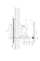
図1は、本発明の第1の実施形態における画像読取装置を表す図面であり、同図において、1は読み取りユニット、2はステッピングモーター、3はベルト、4は原稿台ガラス、5は制御基板、6は35mm写真フィルム、7は白色基準板兼原稿規制板、8はフラットケーブル、9は外部コンピューター、101は読み取りユニット1を取り付けるホルダ、102は35mm写真フィルム6を格納するフィルムガイド(フィルムホルダ)、103はフィルム用光源ユニット、104は103と制御基板5を接続するためのケーブル、105は原稿規制板である。
【0010】
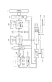
図2は、制御基板5に内蔵される処理回路の構成を示すブロック図である。以下、図2を用いて本件の回路動作を説明する。
【0011】
図2において、読み取りユニット1は、図1に示した原稿台ガラス4上に載置される反射原稿、又はフィルムガイド101に格納された写真フィルム6の画像を読み取るための読み取りユニットであり、反射原稿照明用光源であるLED1201Cもこの読み取りユニット1に一体化されている。読み取りユニット1を原稿台4の原稿面に沿って移動させながら、LED制御回路1201Bにて1ライン毎に各色のLEDを切り替えて点灯させることにより、R,G,B線順次のカラー画像を読み取ることが可能である。
【0012】
なお、LED1201B自体は白色光を照射するようなものを用いて、LED1201Bから原稿までのLEDの光路上にR,G,B(又はC,M,Y,Kでもよい)の光学的な色フィルターを設け、上述と同様の手法により各色の順次のカラー画像を読み取るようにしてもよい。
【0013】
1202は、CIS1201より出力された信号を増幅させる増幅器であり、1203は当該増幅出力のA/D変換を行なって例えば8ビットのディジタル出力を得るA/D変換器である。シェーディングRAM1205は、白色シェーディング板を予め読み取ることによりシェーディング補正用のデータが記憶されるものであり、シェーディング補正回路1204は、前記シェーディングRAM1205のデータに基いて読み取られた画像信号のシェーディング補正を行なう。
【0014】
ガンマ変換回路1206は、ホストコンピュータより。予め設定されたガンマカーブに従って読み取られた画像データのガンマ変換を行なう。バッファRAM1208は、実際の読取動作とホストコンピュータとの通信におけるタイミングとを合わせるために、画像データを1次的に記憶させるためのRAMであり、パッキング/バッファRAM制御回路1207は、ホストコンピュータより予め設定された画像出力モード(2値、4ビット多値、8ビット多値、24ビット多値)に従ったパッキング処理を行った後にそのデータをバッファRAM1208に書き込む処理を行い、インターフェース回路1209にバッファRAM1208から画像データを読み込んで出力させる。
【0015】
インターフェース回路1209は、パーソナルコンピュータなどの本実施形態に係る画像読取装置のホスト装置となる外部装置9との間でコントロール信号の受容や画像信号の出力を行なう。1213は、例えばマイクロコンピュータ形態のCPUであり、処理手順を格納したROM1213A及び作業用のRAM1213Bを有し、ROM1213Aに格納された手順に従って各部の制御を行なう。1212は例えば水晶発振器であり、1211はCPU1213の設定に応じて発振器1212の出力を分周して動作の基準となる各種タイミング信号を発生するタイミング信号発生回路である。
【0016】
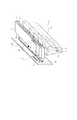
図3は、読み取りユニット1の構成図であり、10は赤色LED、11は緑色LED、12は青色LED、13は導光体である。また、14は第1の光電変換素子アレイ、15は第1のロッドレンズアレイ、201は第2の光電変換素子アレイ、202は第2のロッドレンズアレイであり、16は第1および第2の光電変換素子アレイを取り付ける基板である。
【0017】
基板16には、第1の光電変換素子アレイ14と第2の光電変換素子アレイ201が平行に配列されている。また、第1のロッドレンズアレイ15が第1の光電変換素子アレイ14に対応するように配置され、第2のロッドレンズアレイ202が第2の光電変換素子アレイ201に対応するように配置されている。
【0018】
図4は、第1のロッドレンズアレイ15および第2のロッドレンズアレイ202の被写界深度を説明するための図である。
【0019】
図4(a)において、TypeAは第1のロッドレンズアレイ15に用いられるロッドレンズ、TypeBは第2のロッドレンズアレイ202に用いられるロッドレンズを示している。TCは、TypeAおよびTypeBを側面から見た場合の焦点位置間の距離(共役長)を表す。この例ではTypeAの共役長TC=15.1mm、TypeBの共役長TC=15.6mmである。図4(b)のグラフは、TypeAの焦点位置からΔL離れたときの空間周波数MTFの変化を示す。TypeBはTypeAに比べて若干変化がゆるやかだが、ほぼ同じ特性を持つ。
【0020】
ここで、MTFの計算式は次の(1)式で表される。
MTF=(白濃度最小値−黒濃度最大値)/(基準白濃度値−基準黒濃度値)・・・・・・(1)
【0021】
この実施形態では、図4(c)中に示す170μm毎にならんだ白と黒の線が描かれた原稿をΔL離れた位置に置いて、それを読み取った画像から算出する。読み取った画像データの白濃度最小値と黒濃度最大値と、原稿の濃度を基準白濃度と基準黒濃度として算出する。
【0022】
MTFは解像力を示す指標であるが、ΔLが大きくなると像がぼやけてMTF値が低下してくる。本実施形態の170μm毎の線が描かれた原稿で測定した場合では、MTFが40%以上であれば実用範囲内である。図4(b)のグラフから分かるように、MTFはΔL=0mmの時にピークになり、約82%あるが、その位置から約0.25mm離れると、MTF値が約40%以下になってしまう。
【0023】
つぎに、装置動作の概要を説明する。
【0024】
図1において、制御基板5によりステッピングモーター2が駆動される。この駆動力はベルト3によってホルダ101、すなわち読み取りユニット1に伝達され、読み取りユニット1は原稿台ガラス4に沿って連続的に移動しながら原稿台ガラス4上に置かれた反射原稿又はフィルムガイド(フィルムホルダ)102に格納された透過原稿(写真フィルム)6を走査する。
【0025】
ここで、光電変換素子アレイとロッドレンズアレイについて説明する。図2に示されるように、読み取りユニット1に取り付けられた第1の光電変換素子アレイ14および第2の光電変換素子アレイ201は、読み取りユニット1の長軸方向に沿って伸びるように配置されている。
【0026】
本実施形態の場合、第1の光電変換素子アレイ14はA4サイズの反射原稿を読み取るために用意されている。そのためにA4サイズ原稿の短手方向(210mm)に600DPI相当の密度(解像度)で読み取り可能なように、645素子を持つ光電変換セルが8個、直線状に配置されていて、合計で5160画素分の光電変換素子が基板16上に並んでいる。これは約219mmの読取画像長(読取幅)となり、A4サイズの短手方向に対して平行に移動して読み取るのに適している。
【0027】
また、第1の光電変換素子アレイ14に対応する第1のロッドレンズアレイ15は、その有効結像範囲(結像幅)が第1の光電変換素子アレイ14の読取画像長(読取幅)と同じ約219mmになるように配列されている。
【0028】
一方、第2の光電変換素子アレイ201は、35mm写真フィルム6などの透過原稿を高解像度で高速に読み取るために用意されている。そのために2400DPI相当の密度(解像度)で読み取り可能なように、2576素子を持つ光電変換セルが1個設置されている。これは約27mmの読取画像長(読取幅)となり、35mm写真フィルムの短手方向の大きさが約24mmであるから、35mm写真フィルムを短手方向に対して平行に移動して読み取るのに適している。また読取画像長が短いことから2400DPIでA4サイズ(210mm)の読取画像長にした場合に比べて、1ラインあたりの画像転送速度が早くなり、かつコストも安くできる。
【0029】
また、第2の光電変換素子アレイ201に対応する第2のロッドレンズアレイ202は、その有効結像範囲(結像幅)が第2の光電変換素子アレイ201の読取画像長(読取幅)と同じ約27mmになるように配列されている。
【0030】
それでは最初に、反射原稿を読み取る場合を説明する。
【0031】
図5は反射原稿401を読み取る場合の装置断面図である。
【0032】
赤色LED10、緑色LED11および青色LED12から照射された光は、図3に示すように導光体13によって読み取りユニット1の長軸方向(長手方向)に導かれた後、原稿台ガラス4の上面を照射する。この光は原稿台ガラス4の上面に置かれた反射原稿401で反射され、第1のロッドレンズアレイ15により集光されて第1の光電変換素子14上に投射される。図4を用いて前述したように、第1のロッドレンズアレイ15の共役長(TC)は15.1mmであり、原稿台ガラス4の上面0mm(第1の焦点位置)と光電変換素子アレイ14上に最適な焦点を結ぶ位置に設置され、また、反射原稿401の画像を等倍で第1の光電変換素子アレイ14上に投射する。反射原稿401で反射したLED10,11,12の照射光を受けて、第1の光電変換素子アレイ14には電荷が蓄積され、つぎの周期の読み取り開始パルス(Hsync)で第1の光電変換素子アレイ14内の転送部に保存され、画素読み取りクロック(Clock)によって1画素毎の電気信号として出力される。
【0033】
赤色LED10、緑色LED11および青色LED12の点灯は、読み取り開始パルス(Hsync)毎に切り換えられる。読み取りユニット1の移動に連れて、各LED10,11,12を順次点灯させる。各LED10,11,12によって色分解されて検出された画像信号は、フラットケーブル8を通して制御基板5から外部コンピューター9に送られ、外部コンピューター9内で画像処理が行われる。
【0034】
つぎに、透過原稿として、35mm写真フィルムを読み取る場合を説明する。
【0035】
図6は、35mm写真フィルム6を読み取る場合に用いるフィルム用光源ユニット103およびフィルムガイド(フィルムホルダ)102の構成図である。
【0036】
フィルム用光源ユニット103は拡散板17、フィルム用赤色LED18、フィルム用緑色LED19およびフィルム用青色LED20を内部に持つ。本実施形態の拡散板17は例えば特開2001−34210号公報に記載の面光源を用いることができる。各LEDから照射された光は拡散板17で拡散され、図中の拡散板下面から均一の光が発せられる。この実施形態の拡散板17は、その大きさが50mm×25mmであり、35mm写真フィルム6の1コマ分の有効画像領域:約36mm×24mmを照射することができる。
【0037】
35mm写真フィルム6はフィルムガイド102に格納されている。フィルムガイド102は、原稿台ガラス4(図5中には示していない)上に設置されるが、その際、35mm写真フィルム6が読み取りユニット1内の第2の光電変換素子アレイ201の有効読取範囲内に入るように設置される。
【0038】
図7はフィルムガイド102の構成図で、図に示すように、窓枠601に35mm写真フィルム6を設置して、フィルム挟み602で固定する。窓枠の厚みは約0.5mmある。これによって35mm写真フィルム6は、原稿台ガラス4上に設置した時に原稿台ガラス4上の第1の焦点位置から約0.5mm浮いた第2の焦点位置に設置されることになる。
【0039】
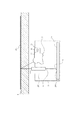
図8は35mm写真フィルム6を読み取る際の装置の断面図である。
【0040】
フィルム用光源ユニット103から照射されるフィルム用赤色LED18,フィルム用緑色LED19およびフィルム用青色LED20からの照射光は、第2の焦点位置にある35mm写真フィルム6を透過して第2のロッドレンズアレイ202により集光されて第2の光電変換素子201上に投射される。図4を用いて前述したように、第2のロッドレンズアレイ202の共役長(TC)は15.6mmであり、原稿台ガラス4の上面から0.5mm離れた第2の焦点位置と光電変換素子アレイ201上に最適な焦点を結ぶ位置に設置され、また、35mm写真フィルム6の画像を等倍で第2の光電変換素子アレイ201上に投射する。35mm写真フィルム6を透過したLED18,19,20の光を受けて、第2の光電変換素子アレイ201には電荷が蓄積される。これ以降の動作は前述した反射原稿の場合と同じである。なお、反射原稿を読み取る場合に用いる第1の光電変換素子アレイの出力信号と透過原稿を読み取る場合に用いる第2の光電変換素子アレイ201の出力信号は、ともに図2に示した同じ処理回路により処理される。
【0041】
35mm写真フィルム6は、原稿台ガラス4から約0.5mm浮いて設置されているが、第2のロッドレンズアレイ202を用いることにより、焦点位置を合わせることができ、適正な解像力で画像を読み取ることができる。
【0042】
以上説明したように本実施形態によれば、反射原稿の読み取り時には、反射原稿に適した、解像度と読取画像長を持つ画像読み取り素子アレイおよび焦点距離をもつロッドレンズアレイを用い、透過原稿の読み取り時には、透過原稿に適した、解像度と読取画像長を持つ画像読み取り素子アレイおよび焦点距離をもつロッドレンズアレイを用いることで、1つの画像読み取りユニット、およびそれを用いた画像読取装置において、反射原稿と透過原稿とで、それぞれ最適な条件で画像を読み込むことが可能になる。
【0043】
また、反射原稿に比べて高い解像度を要求される透過原稿の読取において、コストの高い高解像度の読取素子の長さを必要最小限にすることが可能である。これにより、反射原稿と透過原稿の兼用で1つの長い高解像度の読取素子を用いる場合に比べて装置のコストダウンと読み取り速度の向上が可能になる。
【0044】
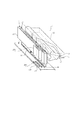
(第2の実施形態)
図9は、第2の実施形態における読み取りユニット1の構成図である。図5に示した第1の実施形態と基本的な構成は同じであるが、第2のロッドレンズアレイ203として、第1のロッドレンズアレイ15と同じ共役長を有するものを用いている点が異なる。また、それに伴って、第1の光電変換素子アレイ14が取り付けられる基板16に第2の光電変換素子アレイ201を直接配置するのではなく、0.5mm厚程度の高さ調整部材204を基板16上に取り付け、さらにその上に第2の光電変換素子アレイ201を取り付けている点も異なる。それ以外の構成は図5に示したものと同じである。
【0045】
図10は、反射原稿401を読み取る場合の装置断面図である。
【0046】
赤色LED10、緑色LED11および青色LED12から照射された光は、図10に示すように導光体13によって読み取りユニット1の長軸方向(長手方向)に導かれた後、原稿台ガラス4の上面を照射する。この光は原稿台ガラス4の上面に置かれた反射原稿401で反射され、第1のロッドレンズアレイ15により集光されて第1の光電変換素子14上に投射される。第1のロッドレンズアレイ15の共役長(TC)は15.1mmであり、原稿台ガラス4の上面0mm(第1の焦点位置)と光電変換素子アレイ14上に最適な焦点を結ぶ位置に設置され、また、反射原稿401の画像を等倍で第1の光電変換素子アレイ14上に投射する。
これ以降の動作は前述した第1の実施形態の場合と同じである。
【0047】
図11は、35mm写真フィルム6を読み取る際の装置の断面図である。
【0048】
フィルム用光源ユニット103から照射されるフィルム用赤色LED18,フィルム用緑色LED19およびフィルム用青色LED20からの照射光は、第2の焦点位置にある35mm写真フィルム6を透過して第2のロッドレンズアレイ202により集光されて第2の光電変換素子201上に投射される。第2のロッドレンズアレイ203の共役長(TC)は第1のロッドレンズアレイ15と同じ15.1mmであるが、原稿台ガラス4の上面から0.5mm離れた第2の焦点位置と光電変換素子アレイ201上に最適な焦点を結ぶように第1のロッドレンズアレイ15よりも0.5mm程度ずらした位置に設置され、35mm写真フィルム6の画像を等倍で第2の光電変換素子アレイ201上に投射する。35mm写真フィルム6を透過したLED18,19,20の光を受けて、第2の光電変換素子アレイ201には電荷が蓄積される。これ以降の動作は前述した反射原稿の場合と同じである。
【0049】
第2のロッドレンズアレイ203を用いることにより、原稿台ガラス4から約0.5mm浮いて設置されている35mm写真フィルム6の画像を適正な解像力で読み取ることができる。
【0050】
【発明の効果】
以上説明したように、本発明によれば、原稿に応じた最適な条件で画像を読み取ることが可能になる。
【図面の簡単な説明】
【図1】本発明の第1の実施形態における画像読取装置の基本的な構成を表す概略図である。
【図2】本発明の第1の実施形態における画像読取装置の処理回路の構成ブロック図である。
【図3】本発明の第1の実施形態における画像読取装置の読み取りユニットの構成図である。
【図4】本発明の第1の実施形態における読み取りユニットのロッドレンズの特性を示す図である。
【図5】本発明の第1の実施形態における反射原稿読み取り時の構成の断面図である。
【図6】本発明の第1の実施形態における35mm写真フィルムの読み取り構成図である。
【図7】本発明の第1の実施形態における35mm写真フィルムのフィルムガイドへの装着方法を示す図である。
【図8】本発明の第1の実施形態における35mm写真フィルム読み取り構成の断面図である。
【図9】本発明の第2の実施形態における画像読取装置の読み取りユニットの構成図である。
【図10】本発明の第2の実施形態における反射原稿読み取り時の構成の断面図である。
【図11】本発明の第2の実施形態における35mm写真フィルム読み取り構成の断面図である。
【符号の説明】
1 読み取りユニット
2 ステッピングモーター
3 ベルト
4 原稿台ガラス
5 制御基板
6 35mm写真フィルム
7 白色基準板兼・原稿規制板
8 フラットケーブル
9 外部コンピューター
10 赤色LED
11 緑色LED
12 青色LED
13 導光体
14 第1の光電変換素子アレイ
15 第1のロッドレンズアレイ
16 基板
17 拡散板
18 フィルム用赤色LED
19 フィルム用緑色LED
20 フィルム用青色LED
101 ホルダ
102 ガイド(フィルムホルダ)
103 フィルム用光源ユニット
104 ケーブル
105 原稿規制板
201 第2の光電変換素子アレイ
202 第2のロッドレンズアレイ
203 第2のロッドレンズアレイ
401 反射原稿[0001]
TECHNICAL FIELD OF THE INVENTION
The present invention provides an image reading unit having an image reading element array in which a plurality of photoelectric conversion elements are linearly arranged, and a reflection original such as a printed matter and a transparent original such as a photographic film using the reading unit. The present invention relates to an image reading device having a reading function.
[0002]
[Prior art]
Conventionally, when a transparent original such as a photographic film is read by a flatbed type image reading device having an original platen glass, the transparent original is installed on the transparent original guide unit and set on the original platen glass, and the transparent original The method of irradiating with a surface light source unit from the top is the mainstream. In general, an image reading apparatus of this type is designed so that the position where the focus is most focused is the position of the upper surface of the
[0003]
In the case of a lens of a reduction optical system using a CCD, this method has no practical problem even if the depth of field is deep and the distance between the platen glass and the transparent original is about 0.5 mm.
[0004]
[Problems to be solved by the invention]
However, in recent years, a reading unit of the same magnification optical system using a rod lens array has appeared for the purpose of miniaturization. Since the depth of field of the rod lens array is shallow, if the distance between the platen glass and the transparent original is about 0.5 mm, there is a problem that the focus is blurred.
[0005]
The present invention has been made in view of the above circumstances, and has as its object to provide an image reading apparatus capable of effectively and appropriately reading images of both a reflective original and a transparent original.
[0006]
[Means for Solving the Problems]
The image reading unit according to
[0007]
The image reading unit according to claim 3, wherein a first image reading element array in which a plurality of photoelectric conversion elements are arranged in a line, and a plurality of photoelectric conversion elements in parallel with the first image reading element array. Are arranged in a line, the second image reading element array having a higher resolution than the first image reading element array, and the first original image at the first focal position is read in the first column of image reading elements. A first lens that forms an image on the array, and a second lens that forms a second document image at a second focus position different from the first focus position on the image reading element array in the second row. And a lens.
[0008]
BEST MODE FOR CARRYING OUT THE INVENTION
Hereinafter, preferred embodiments of an image reading apparatus according to the present invention will be described with reference to the drawings.
[0009]
(1st Embodiment)
FIG. 1 is a view showing an image reading apparatus according to a first embodiment of the present invention. In FIG. 1, 1 is a reading unit, 2 is a stepping motor, 3 is a belt, 4 is a platen glass, and 5 is a control board. , 6 is a 35 mm photographic film, 7 is a white reference plate / document regulating plate, 8 is a flat cable, 9 is an external computer, 101 is a holder for mounting the
[0010]
FIG. 2 is a block diagram illustrating a configuration of a processing circuit built in the control board 5. Hereinafter, the circuit operation of the present case will be described with reference to FIG.
[0011]
2, a
[0012]
The LED 1201B itself emits white light, and an R, G, B (or C, M, Y, K) optical color filter is provided on the optical path of the LED from the LED 1201B to the document. May be provided, and a sequential color image of each color may be read in the same manner as described above.
[0013]
[0014]
The
[0015]
The interface circuit 1209 receives a control signal and outputs an image signal with an external device 9 serving as a host device of the image reading apparatus according to the present embodiment, such as a personal computer.
[0016]
FIG. 3 is a configuration diagram of the
[0017]
On the
[0018]
FIG. 4 is a diagram for explaining the depth of field of the first
[0019]
In FIG. 4A, Type A indicates a rod lens used in the first
[0020]
Here, the calculation formula of MTF is represented by the following formula (1).
MTF = (minimum white density−maximum black density) / (reference white density value−reference black density value) (1)
[0021]
In this embodiment, a document on which white and black lines drawn every 170 μm shown in FIG. 4C are drawn is placed at a position apart by ΔL and is calculated from the read image. The minimum white density value and the maximum black density value of the read image data and the density of the document are calculated as the reference white density and the reference black density.
[0022]
MTF is an index indicating the resolving power, but when ΔL increases, the image becomes blurred and the MTF value decreases. In the present embodiment, when the measurement is performed on a document on which a line of every 170 μm is drawn, if the MTF is 40% or more, it is within the practical range. As can be seen from the graph of FIG. 4B, the MTF peaks when ΔL = 0 mm and is about 82%, but when it is away from that position by about 0.25 mm, the MTF value becomes about 40% or less. .
[0023]
Next, an outline of the operation of the apparatus will be described.
[0024]
In FIG. 1, the stepping motor 2 is driven by the control board 5. This driving force is transmitted to the
[0025]
Here, the photoelectric conversion element array and the rod lens array will be described. As shown in FIG. 2, the first photoelectric
[0026]
In the case of the present embodiment, the first photoelectric
[0027]
The first
[0028]
On the other hand, the second photoelectric
[0029]
The second
[0030]
First, a case of reading a reflection original will be described.
[0031]
FIG. 5 is a cross-sectional view of the apparatus when the reflection original 401 is read.
[0032]
Light emitted from the
[0033]
Lighting of the
[0034]
Next, a case where a 35 mm photographic film is read as a transparent original will be described.
[0035]
FIG. 6 is a configuration diagram of the film
[0036]
The film
[0037]
The 35 mm photographic film 6 is stored in the
[0038]
FIG. 7 is a configuration diagram of the
[0039]
FIG. 8 is a cross-sectional view of the apparatus when reading a 35 mm photographic film 6.
[0040]
Irradiation light from the film
[0041]
The 35 mm photographic film 6 is set so as to float about 0.5 mm from the
[0042]
As described above, according to the present embodiment, when reading a reflective original, an image reading element array having a resolution and a read image length suitable for the reflective original and a rod lens array having a focal length are used to read a transparent original. Sometimes, by using an image reading element array having a resolution and a read image length and a rod lens array having a focal length suitable for a transparent original, one image reading unit and an image reading apparatus using the same can be used as a reflection original. It is possible to read an image under optimum conditions for the original and the transparent original.
[0043]
Further, in reading a transparent original requiring a higher resolution than a reflective original, it is possible to minimize the length of a high-cost high-resolution reading element. As a result, the cost of the apparatus can be reduced and the reading speed can be improved as compared with the case where one long high-resolution reading element is used for both the reflection document and the transmission document.
[0044]
(Second embodiment)
FIG. 9 is a configuration diagram of the
[0045]
FIG. 10 is a sectional view of the apparatus when reading the reflection original 401.
[0046]
Light emitted from the
Subsequent operations are the same as those in the first embodiment.
[0047]
FIG. 11 is a cross-sectional view of the apparatus when reading a 35 mm photographic film 6.
[0048]
Irradiation light from the film
[0049]
By using the second
[0050]
【The invention's effect】
As described above, according to the present invention, it is possible to read an image under optimal conditions according to the document.
[Brief description of the drawings]
FIG. 1 is a schematic diagram illustrating a basic configuration of an image reading apparatus according to a first embodiment of the present invention.
FIG. 2 is a configuration block diagram of a processing circuit of the image reading device according to the first embodiment of the present invention.
FIG. 3 is a configuration diagram of a reading unit of the image reading apparatus according to the first embodiment of the present invention.
FIG. 4 is a diagram illustrating characteristics of a rod lens of the reading unit according to the first embodiment of the present invention.
FIG. 5 is a cross-sectional view of a configuration when reading a reflection original according to the first embodiment of the present invention.
FIG. 6 is a configuration diagram of reading a 35 mm photographic film according to the first embodiment of the present invention.
FIG. 7 is a diagram illustrating a method of mounting a 35 mm photographic film on a film guide according to the first embodiment of the present invention.
FIG. 8 is a sectional view of a 35 mm photographic film reading configuration according to the first embodiment of the present invention.
FIG. 9 is a configuration diagram of a reading unit of an image reading device according to a second embodiment of the present invention.
FIG. 10 is a cross-sectional view of a configuration when reading a reflective original according to a second embodiment of the present invention.
FIG. 11 is a sectional view of a 35 mm photographic film reading configuration according to a second embodiment of the present invention.
[Explanation of symbols]
REFERENCE SIGNS
11 Green LED
12 Blue LED
13
19 Green LED for film
20 Blue LED for film
103 Film
Claims (12)
前記第1の画像読み取り素子アレイと平行して複数の光電変換素子をライン状に配列した第2の画像読み取り素子アレイと、
第1の焦点位置にある第1の原稿画像を前記第1列の画像読み取り素子アレイ上に結像させる第1のレンズと、
前記第1のレンズとは共役長が異なり、前記第1の焦点位置と異なる第2の焦点位置にある第2の原稿画像を前記第2列の画像読み取り素子アレイ上に結像させる第2のレンズと、
を備えたことを特徴とする画像読取ユニット。A first image reading element array in which a plurality of photoelectric conversion elements are arranged in a line,
A second image reading element array in which a plurality of photoelectric conversion elements are arranged in a line in parallel with the first image reading element array;
A first lens that forms an image of a first document at a first focal position on the image reading element array in the first row;
A second original image having a conjugate length different from that of the first lens and located at a second focal position different from the first focal position on the image reading element array in the second row; Lens and
An image reading unit comprising:
前記第1の画像読み取り素子アレイと平行して複数の光電変換素子がライン状に配列され、前記第1の画像読み取り素子アレイよりも高解像度な第2の画像読み取り素子アレイと、
第1の焦点位置にある第1の原稿画像を前記第1列の画像読み取り素子アレイ上に結像させる第1のレンズと、
前記第1の焦点位置と異なる第2の焦点位置にある第2の原稿画像を前記第2列の画像読み取り素子アレイ上に結像させる第2のレンズと、
を備えたことを特徴とする画像読取ユニット。A first image reading element array in which a plurality of photoelectric conversion elements are arranged in a line,
A plurality of photoelectric conversion elements arranged in a line in parallel with the first image reading element array, and a second image reading element array having a higher resolution than the first image reading element array;
A first lens that forms an image of a first document at a first focal position on the image reading element array in the first row;
A second lens that forms a second document image at a second focal position different from the first focal position on the image reading element array in the second row;
An image reading unit comprising:
Priority Applications (1)
| Application Number | Priority Date | Filing Date | Title |
|---|---|---|---|
| JP2002291157A JP2004126284A (en) | 2002-10-03 | 2002-10-03 | Image read unit and image reader |
Applications Claiming Priority (1)
| Application Number | Priority Date | Filing Date | Title |
|---|---|---|---|
| JP2002291157A JP2004126284A (en) | 2002-10-03 | 2002-10-03 | Image read unit and image reader |
Publications (2)
| Publication Number | Publication Date |
|---|---|
| JP2004126284A true JP2004126284A (en) | 2004-04-22 |
| JP2004126284A5 JP2004126284A5 (en) | 2005-06-23 |
Family
ID=32282823
Family Applications (1)
| Application Number | Title | Priority Date | Filing Date |
|---|---|---|---|
| JP2002291157A Pending JP2004126284A (en) | 2002-10-03 | 2002-10-03 | Image read unit and image reader |
Country Status (1)
| Country | Link |
|---|---|
| JP (1) | JP2004126284A (en) |
Cited By (8)
| Publication number | Priority date | Publication date | Assignee | Title |
|---|---|---|---|---|
| CN100361491C (en) * | 2004-08-13 | 2008-01-09 | 菱光科技股份有限公司 | Contact type image scanner with multi-focus and multi resolution ratio |
| US7339150B2 (en) | 2004-10-29 | 2008-03-04 | Seiko Epson Corporation | Imaging unit and image reading apparatus |
| US7391543B2 (en) | 2004-07-23 | 2008-06-24 | Seiko Epson Corporation | Image reading apparatus |
| US7535602B2 (en) | 2004-07-23 | 2009-05-19 | Seiko Epson Corporation | Image reading apparatus |
| JP2010022021A (en) * | 2009-09-01 | 2010-01-28 | Seiko Epson Corp | Image reader |
| JP2012250413A (en) * | 2011-06-02 | 2012-12-20 | Konica Minolta Business Technologies Inc | Image forming device |
| JP2013541722A (en) * | 2010-08-24 | 2013-11-14 | ウエイハイ ホアリン オプト−エレクトロニクス カンパニー リミテッド | Composite rod lens array and image reading apparatus constituted by composite rod lens array |
| CN107767414A (en) * | 2017-10-24 | 2018-03-06 | 林嘉恒 | The scan method and system of mixed-precision |
-
2002
- 2002-10-03 JP JP2002291157A patent/JP2004126284A/en active Pending
Cited By (8)
| Publication number | Priority date | Publication date | Assignee | Title |
|---|---|---|---|---|
| US7391543B2 (en) | 2004-07-23 | 2008-06-24 | Seiko Epson Corporation | Image reading apparatus |
| US7535602B2 (en) | 2004-07-23 | 2009-05-19 | Seiko Epson Corporation | Image reading apparatus |
| CN100361491C (en) * | 2004-08-13 | 2008-01-09 | 菱光科技股份有限公司 | Contact type image scanner with multi-focus and multi resolution ratio |
| US7339150B2 (en) | 2004-10-29 | 2008-03-04 | Seiko Epson Corporation | Imaging unit and image reading apparatus |
| JP2010022021A (en) * | 2009-09-01 | 2010-01-28 | Seiko Epson Corp | Image reader |
| JP2013541722A (en) * | 2010-08-24 | 2013-11-14 | ウエイハイ ホアリン オプト−エレクトロニクス カンパニー リミテッド | Composite rod lens array and image reading apparatus constituted by composite rod lens array |
| JP2012250413A (en) * | 2011-06-02 | 2012-12-20 | Konica Minolta Business Technologies Inc | Image forming device |
| CN107767414A (en) * | 2017-10-24 | 2018-03-06 | 林嘉恒 | The scan method and system of mixed-precision |
Similar Documents
| Publication | Publication Date | Title |
|---|---|---|
| US7471428B2 (en) | Contact image sensor module and image reading device equipped with the same | |
| US7633656B2 (en) | Image reading unit and image reading apparatus having the same | |
| US7535602B2 (en) | Image reading apparatus | |
| US7391543B2 (en) | Image reading apparatus | |
| JP3507284B2 (en) | Rod lens array, contact image sensor and image reading device | |
| US7894105B2 (en) | Image reading unit and image reader | |
| US6278101B1 (en) | Method for increasing the native resolution of an image sensor | |
| TW200305774A (en) | Image reading apparatus | |
| EP0822706A2 (en) | Image reading apparatus and image reading system | |
| JP2004126284A (en) | Image read unit and image reader | |
| JP2985959B1 (en) | Color imaging apparatus and image reading apparatus using the same | |
| EP0822705A2 (en) | Image reading apparatus and image reading system | |
| US6859233B1 (en) | Auto focus mechanism in image input apparatus | |
| JP2003037713A (en) | Image reader | |
| JP2004221729A (en) | Close contact type image sensor and close contact type image reader using the same | |
| JP5118083B2 (en) | Dual mirror lighting system for book copier | |
| US20040164222A1 (en) | Systems and methods for providing multiple object planes in an optical image scanner | |
| JP2003037712A (en) | Image reader | |
| CN1194528C (en) | Scanning method and device with raised resolution | |
| JP2003215726A (en) | Image reader and lighting unit | |
| US20040164223A1 (en) | Automatic object plane selection in an optical image scanner | |
| JP2003046729A (en) | Image reader | |
| TWI275297B (en) | Optical image scanner with reduced optical head profile | |
| US20040119417A1 (en) | Scanner with common illumination light source | |
| JP2002111978A (en) | Image reader |
Legal Events
| Date | Code | Title | Description |
|---|---|---|---|
| A521 | Written amendment |
Free format text: JAPANESE INTERMEDIATE CODE: A523 Effective date: 20040930 |
|
| A621 | Written request for application examination |
Free format text: JAPANESE INTERMEDIATE CODE: A621 Effective date: 20040930 |
|
| A977 | Report on retrieval |
Free format text: JAPANESE INTERMEDIATE CODE: A971007 Effective date: 20060712 |
|
| A131 | Notification of reasons for refusal |
Free format text: JAPANESE INTERMEDIATE CODE: A131 Effective date: 20060926 |
|
| A521 | Written amendment |
Free format text: JAPANESE INTERMEDIATE CODE: A523 Effective date: 20061124 |
|
| A131 | Notification of reasons for refusal |
Free format text: JAPANESE INTERMEDIATE CODE: A131 Effective date: 20070306 |
|
| A02 | Decision of refusal |
Free format text: JAPANESE INTERMEDIATE CODE: A02 Effective date: 20070626 |