JP2004120147A - Image photographing apparatus - Google Patents
Image photographing apparatus Download PDFInfo
- Publication number
- JP2004120147A JP2004120147A JP2002278420A JP2002278420A JP2004120147A JP 2004120147 A JP2004120147 A JP 2004120147A JP 2002278420 A JP2002278420 A JP 2002278420A JP 2002278420 A JP2002278420 A JP 2002278420A JP 2004120147 A JP2004120147 A JP 2004120147A
- Authority
- JP
- Japan
- Prior art keywords
- unit
- recording
- flash
- image photographing
- photographing apparatus
- Prior art date
- Legal status (The legal status is an assumption and is not a legal conclusion. Google has not performed a legal analysis and makes no representation as to the accuracy of the status listed.)
- Withdrawn
Links
Images


Landscapes
- Studio Devices (AREA)
Abstract
Description
【0001】
【発明の属する技術分野】
本発明は、録音機能を有する画像撮影装置、さらに詳しくいえば静止画や動画を撮影できるカメラのマイクの配置に関する。
最初に、本発明の明細書に用いている「立設」という語句は、撮影時または録音時に装置面から突出する場合のみではなく、当初から装置面から突出している場合も含み、さらに「フラッシュ」は、ストロボだけではなくLEDなどの照明のようなものも含むと定義する。
【0002】
【従来の技術】
静止画や動画を撮影できるカメラとしてディジタルカメラが近年普及している。ディジタルカメラは、メモリ容量増大化に伴い静止画のみならず音声とともに動画も撮影できる機能が搭載されるようになってきている。
動画撮影では動画撮影モードを選択した後、レリーズボタンをオンすることにより音声及び動画の取り込みが行われる。
ディジタルカメラは、本来静止画を撮影しやすいように外観がデザインされており、左右の手でカメラ外形の左端と右端を把持し、右手の人指し指でカメラ上面のレリーズボタンを押す構えとなる。左手はカメラ外形左端を親指と残りの指で掴む構えとなる。
【0003】
【発明が解決しようとする課題】
ところで、マイクをカメラの側面に設けた場合、一方の側面に設けると反対側の音は録音感度が低下する。カメラの正面と背面の一方にマイクを設けた場合も同様、背面にマイクを設けた場合は被写体の録音感度が低下し、さらに正面に設けた場合は撮影者の録音感度が低下する。正面に設けた場合は撮影者の録音感度が低下する。さらにはカメラの下面にマイクを設けた場合は、下は大地等であり、これによっても録音感度は低下する。したがって、装置上面に設けたものが録音感度が高くなる。
また、近年装置の小型化が要求されているが、従来のレンズやズーム機構,液晶等などの表示装置を組み合わせて構成したものに、マイク等の録音部を設けると装置が大型化する。したがって、録音部を装置上面端に設けることにより、装置の大型化を防止し、装置全体の小型化を図ることができる。
【0004】
そこで音声を取り込むマイクは、被写体と撮影者両者の音声を録音することが必要であることから、カメラ上面に設けられ、しかも無指向性のマイクを用いることが考えられる。
しかしながら、カメラを把持する場合、撮影時、撮影者の神経は被写体に注がれていることからカメラを握る位置まで気を回すことは少ない。そのため、指がカメラ上面のマイクを覆っていることに気付かず動画撮影を続行してしまうことがある。取り込んだ動画には、音声はほとんど入力されず折角の撮影が台無しになることがしばしば発生する。静止画撮影時の録音に際しても同様のことが起こりうる。
【0005】
また、録音中にボタンが操作されたり、ズーム,フラッシュ動作することによる雑音混入の問題がある。
本発明は、上記問題を解決するもので、その目的は、カメラ撮影時の撮影者の手によりマイクが塞がれることを回避し、雑音の混入を防止することができる画像撮影装置を提供することにある。
【0006】
【課題を解決するための手段】
前記目的を達成するために本発明による画像撮影装置は、以下に示す構成とする。すなわち本発明の請求項1は被写体に光を照射するフラッシュ部と、音声等を録音する録音部を有する画像撮影装置において、少なくとも撮影時に装置上面に立設するフラッシュ部と、該フラッシュ部の近傍に前記録音部を設けた構成とする。
本発明の請求項2は請求項1において装置の上面端付近に指先部を置いて装置を把持する凹部を形成し、該凹部の近傍に前記録音部を設けた構成とする。
本発明の請求項3は請求項2において前記フラッシュ部を装置の前記録音部および凹部よりも中央寄りに設けた構成とする。
本発明の請求項4は請求項3においてフラッシュ部と凹部との間に前記録音部を設けた構成とする。
本発明の請求項5は請求項1において前記フラッシュ部を装置の前記録音部よりも中央寄りに設けた構成とする。
本発明の請求項6は請求項1において装置上面の一方端に操作部を設け、他方端に録音部を設けた構成とする。
本発明の請求項7は請求項1において装置の電源をオンした際に、前記フラッシュ部が立設する構成とする。
本発明の請求項8は請求項1において音声等を録音部にて録音する際に、前記フラッシュ部が立設する構成とする。
本発明の請求項9は請求項1において前記フラッシュ部の背面側を回動支点としてポップアップするように構成し、前記録音部を前記フラッシュ部の回動支点より背後であって、前記フラッシュ部より端側に設けた構成とする。
本発明の請求項10は請求項1において前記録音部による録音中は前記フラッシュ部の光照射を停止する構成とする。
本発明の請求項11は請求項1において装置の上面端付近に操作部を設け、該操作部の近傍に前記録音部を設けた構成とする。
本発明の請求項12は請求項1において前記被写体の拡大や縮小を行うズーム部を備え、前記録音中は該ズーム部の動作を停止する構成とする。
本発明の請求項13は請求個1乃至12において前記被写体の拡大や縮小を行うズーム部を備え、前記録音中は該ズーム部の動作を停止する構成とする。
本発明の請求項14は音を録音する録音部を有する画像撮影装置において、
録音時に装置上面に突出する録音部を設けた構成とする。
本発明の請求項15は、請求項14において装置の上面端付近に指先部を置いて装置を把持する凹部を形成し、該凹部の近傍に前記録音部を設けた構成とする。
本発明の請求項16は請求項15において前記フラッシュ部を装置の前記録音部および凹部よりも中央寄りに設けた構成とする。
本発明の請求項17は請求項16において装置の電源をオンした際に、前記フラッシュ部が立設する構成とする。
本発明の請求項18は請求項16において音声等を録音部にて録音する際に、前記フラッシュ部が立設する構成とする。
本発明の請求項19は請求項16においてフラッシュ部と凹部の間に前記録音部を設けた構成とする。
本発明の請求項20は請求項16において前記録音部による録音中は前記フラッシュ部の光照射を停止する構成とする。
本発明の請求項21は請求項14において装置の上面に少なくとも撮影時に立設し、被写体に光を照射するフラッシュ部を設けた構成とする。
本発明の請求項22は請求項21において前記フラッシュ部を装置の前記録音部および/または凹部よりも中央寄りに設けた構成とする。
本発明の請求項23は請求項21において装置の電源をオンした際に、前記フラッシュ部が立設する構成とする。
本発明の請求項24は請求項21において音声等を録音部にて録音する際に、前記フラッシュ部が立設する構成とする。
本発明の請求項25は請求項21において前記録音部による録音中は前記フラッシュ部の光照射を停止する構成とする。
本発明の請求項26は請求項14において装置上面の一方端に操作部を設け、他方端に録音部を設けた構成とする。
本発明の請求項27は請求項14において装置の上面端付近に操作部を設け、該操作部の近傍に前記録音部を設けた構成とする。
本発明の請求項28は請求項14において前記被写体の拡大や縮小を行うズーム部を備え、前記録音中は該ズーム部の動作を停止する構成とする。
本発明の請求項29は請求項14において前記録音部による録音中は録音停止を実行する操作部のみ操作可能とする構成とする。
本発明の請求項30は音声等を録音する録音部を有する画像撮影装置において、装置上面端付近に指先部を置いて装置を把持する凹部を形成し、前記凹部の近傍に前記録音部を設けた構成とする。
本発明の請求項31は請求項30において装置の上面に少なくとも撮影時に立設し、被写体に光を照射するフラッシュ部を設けた構成とする。
本発明の請求項32は請求項31において装置の電源をオンした際に、前記フラッシュ部が立設する構成とする。
本発明の請求項33は請求項31において音声等を録音部にて録音する際に、前記フラッシュ部が立設する構成とする。
本発明の請求項34は請求項31において前記フラッシュ部の背面側を回動支点としてポップアップするように構成し、前記録音部を前記フラッシュ部の回動支点より背後であって、前記フラッシュ部より端側に設けた構成とする。
本発明の請求項35は請求項31において前記録音部による録音中は前記フラッシュ部の光照射を停止する構成とする。
本発明の請求項36は請求項30において前記フラッシュ部を装置の前記録音部および凹部よりも中央寄りに設けた構成とする。
本発明の請求項37は請求項36において装置の電源をオンした際に、前記フラッシュ部が立設する構成とする。
本発明の請求項38は請求項36において音声等を録音部にて録音する際に、前記フラッシュ部が立設する構成とする。
本発明の請求項39は請求項36においてフラッシュ部と凹部の間に前記録音部を設けた構成とする。
本発明の請求項40は請求項36において前記フラッシュ部の背面側を回動支点としてポップアップするように構成し、前記録音部を前記フラッシュ部の回動支点より背後であって、前記フラッシュ部より端側に設けた構成とする。
本発明の請求項41は請求項36において前記録音部による録音中は前記フラッシュ部の光照射を停止する構成とする。
本発明の請求項42は請求項30において装置の上面端付近に操作部を設け、該操作部の近傍に前記録音部を設けた構成とする。
本発明の請求項43は請求項30において前記被写体の拡大や縮小を行うズーム部を備え、前記録音中は該ズーム部の動作を停止する構成とする。
本発明の請求項44は請求項30において前記録音部による録音中は録音停止を実行する操作部のみ操作可能とする構成とする。
【0007】
【作用】
上記請求項1,21,31によれば、立設したフラッシュが壁となり、装置本体を把持する指は録音部より外れる位置に置かれ指が録音部に被さることはない。
請求項2によれば、録音部が立設するので、指で塞がれる可能性はない。また、フラッシュと同様、被写体方向に録音部を向けた場合、被写体の音声の録音感度を高くすることができる。
上記請求項2,15,30によれば、指先が凹部に誘導されるため、録音部に指が被ることを防止できる。
上記請求項3,5,16,22,36によれば、フラッシュ上面中央に設置することにより装置本体を把持しやすくなり、装置、例えばカメラを構える際のブレを抑えることができる。
上記請求項6,26,42によれば、録音時に操作部による押圧音などの雑音混入を防止することができる。
上記請求項7,8,17,18,23,24,32,33,37,38によれば、電源オン時または録音時にフラッシュが立設すれば、フラッシュを別に立ち上げる入力操作は必要なくなるとともに最適な装置、例えばカメラ把持状態に導くことができる。
上記請求項4,19,39によればフラッシュ部と凹部の間に録音部を設けたことで録音部に指先部が覆い被さろうとしてもフラッシュ部に指先があたり録音部に覆い被さることはないとともに、凹部が設けられていることから、指先はその凹部に誘導され録音部に覆い被さる可能性も少なくなる。
上記請求項9,34,40によれば、ポップアップしたフラッシュが邪魔になり指が録音部を塞ぐことはない。すなわち、動画撮影時に構える左手の指がカバー凹部に自然に誘導され、仮にカバー凹部に誘導されない場合では、上カバーと同じ面に配置される録音部がポップアップしたフラッシュの脇にあるためフラッシュの出っ張りが邪魔となって指は自ずから録音部から外れた位置に置かれる可能性が高く、間違って指が録音部上に被さっても指の一部がポップアップしたフラッシュの上に当たる可能性が高いため、マイクと指の間には隙間が生じ、この隙間から録音が可能となる。
上記請求項10,20,25,35,41によれば、録音中に光源による電気的ノイズやフラッシュ音等の雑音混入を防止することができる。
上記請求項11,27,43によれば、操作部の上に指が自然に置かれるので、指が録音部を覆うことを防止できる。特に操作部が撮影ボタンであれば、録音中にそのボタンを押す必要があることから、その効果は大である。
上記請求項12,13,28,29,44,45によれば、雑音の混入を防止することができる。
【0008】
【発明の実施の形態】
以下、図面を参照して本発明をさらに詳しく説明する。
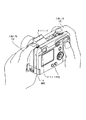
図1は、本発明による画像撮影装置の実施の形態を示すディジタルカメラの外観斜視図、図2は、同じく平面図である。
ディジタルカメラ1の背面にはファインダ接眼部5,液晶画面16,モード切替レバー17が配置されている。カメラの上面の左端(カメラを正面から見た場合、以下同じ)にはレリーズボタン8が、その隣にはパワーボタン7がそれぞれ配置されている。
カメラの上面右寄りにはポップアップするフラッシュ(ストロボ)4が設けられ、フラッシュ4の右側にカバー凹部3が設けられている。カバー凹部3は左手の人指し指が置かれることを予定する凹みである。
カバー凹部3の後ろ側であって、フラッシュ4のポップアップする支点の脇にマイク凹部2が設けられている。
【0009】
図3はマイク付近の構造を示す断面図である。
マイク凹部2の底面にはマイク孔2が穿たれており、マイク孔2の下側に無指向性のマイク12が設置されている。マイク凹部2はリアカバー10に形成され、カバー凹部3はミドルカバー11に形成されている。
フラッシュ4のポップアップ状態では、上面前部は高く持ち上がり、上面後端4bも支点4aを中心に所定の高さだけ持ち上がっている。
【0010】
図4は、図1のディジタルカメラの把持状態を説明するための背面斜視図、図5は同じく正面図である。
この把持状態は左手の人指し指13がカメラ上面のカバー凹部3の部分に置かれ、親指14がカメラ底面を支えている状態を示している。右手の親指はカメラ背面にあてがわれ、人指し指15はレリーズボタン8の上に置かれている。左右の手のその他の指はカメラ前面側を押さえている。
本発明によるマイク配置構造によれば、このような把持状態に自然に導かれ、マイク凹部2の上には指は置かれていない。
【0011】
図6は、右手人指し指がマイク上面に置かれた場合を説明するための背面図である。
しかしながら、撮影者の右手人指し指20がマイク12の上から被さるように置かれた場合には、図に示すように人指し指20の先端部分がポップアップしたフラッシュ上面後端4bの上にも乗り上げることになる。かかる場合にはフラッシュ上面後端4bの高さ分だけ人指し指20の腹が浮き上がるため隙間21ができる。
したがって、仮に右手人指し指20がマイクの上に置かれたとしても録音のためのマイクへの隙間は確保することができる。
なお、ポップアップしたフラッシュ上面後端4bに乗り上げないでマイク12の上に右手人指し指20が置かれた場合にも、フラッシュ上面後端4bの出っ張りが邪魔になるため、マイク凹部2の一部は覆われるものの完全にマイク凹部2を覆うことができない構造である。音声は拡がる性質を持つため少しでも覆われない部分があれば録音に支障を生じることは少ない。
【0012】
また、操作ボタンであるレリーズボタン8の設置位置に対し、マイク凹部2の設置位置はカメラ上面の反対位置に設けられているため、操作ボタンによる押圧音等の雑音が入らないようになる。さらにフラッシュの位置をカメラ上面の中央寄りに設けた場合にはカメラ本体を把持しやすくなり、カメラを構える際のブレの抑制に有利である。
【0013】
図7は、本発明の第2,第3の実施の形態を示す概略図で、(a)はマイクを上面にポップアップするように設けた場合、(b)はマイクを正面に向けてポップアップように設けた場合である。
第2の実施の形態ではカメラ上面24の右端にマイク22が、左端に録音,録画を開始・停止するレリーズボタン23が配置されている。マイク22は録音機能を使用するときにポップアップし、カメラ上面24より上側に突出する。マイクは突出面の上側に設置されている。
第3の実施の形態では、カメラ上面28の右端にマイク27が、左端にレリーズボタン26が配置されている構成は第2の実施の形態と同じであるが、マイク27が正面を向いてポップアップする点で異なっている。これは被写体方向に向けることにより被写体の音声の録音感度を高くしたものである。
いずれの実施の形態もマイクがポップアップするため、録音時、指によって塞がれることはない。
また、図7(a)(b)において、ポップアップしたマイクを回動させることもできる。好ましくはマイク自体に指向性があれば、希望する方向の集中的に集音することができる。
【0014】
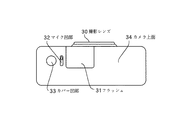
図8は、本発明の第4の実施の形態を示す概略図である。
この実施の形態は、マイク凹部32の設置位置をフラッシュ31のポップアップする脇に設けた点で図1とは異なっており、他の構成部分は同じである。
かメラ上面34の略中央よりにフラッシュ31が配置され、その右側脇(カメラを正面から見た場合)にマイク凹部32が設けられている。その右隣にカバー凹部33が設置されている。フラッシュ31が電源オンでポップアップすると、ポップアップしたフラッシュ31が邪魔になってマイク凹部32の上に人指し指を乗せようとしても安定した状態で乗せることはできない。結局、人指し指はカバー凹部に誘導されることとなり、マイクに人指し指が被さることはない。
【0015】
図9は、本発明の第5の実施の形態を示す概略図である。
この実施の形態は、カメラ上面37の右端に操作ボタンであるレリーズボタン35を配置し、その近傍にマイク凹部36を配置したものである。
左手の人指し指が録音開始,停止操作のためにレリーズボタン25の上に置かれるため、マイク凹部36に人指し指が被さることは少ない。すなわち、撮影中はレリレーズボタンを押すことにより、その部分に指先部が自然におかれる状態となり、録音部に指が被さることはなくなる。
この実施の形態はレリーズボタンや電源のオン・オフ等の操作部を凹部と同様な構成で装置上面に形成するものであり、凹部を設けた構成と同様な効果が得られる。
なお、上記実施の形態においては操作ボタンを入力すると雑音等が録音されるが、録音開始および停止操作において操作ボタンを操作するため、雑音等は録音されない。
以上の第1〜第5の実施の形態は、ディジタルカメラについての例であるが、携帯電話等のカメラ機能付き通信装置等で同じ構成のものであれば同様に適用できる。
【0016】
図10は、動画撮影時の操作シーケンスを説明するためのフローチャートである。動画撮影に際しては図1のモード切替レバー17を動画撮影モードに切り替え、パワーボタン7をオンさせる(ステップ(以下「S」という)101)。
パワーオンによりシステムが起動しズームモータも動作を開始する。これによりフラッシュ4はポップアップし、ズーム回転し撮影レンズ6が撮影位置に繰り出す(S102)。そして、ビューファーがオンしシステム作動可能となる(S103)。撮影者がレリーズオンする(S104)と、動画と音声記録が開始する(S105)。
【0017】
撮影者は図4に示すようにディジタルカメラを把持して構え、撮影を続行する。左手人指し指はマイクに被さることはないので、正常に録音できる。所定の時間で撮影が終了するが、途中で撮影を終了させるにはレリーズボタンを押してオフする(S106)。以上により動画撮影が終了する。
この後は、パワーボタンを押してオフする(S107)ことにより、ズームモータがオンして撮影レンズ6が収納されるとともにフラッシュ4もダウンしシステム動作が完了する(S108,S109)。
以上の操作シーケンスでは録音中、フラッシュは発光しないように構成されている。また、同じく録音中、ズーム機能は働かず、ズーミングが行われないような構成にしても良い。さらに、録音停止指令ボタンのみ作動が可能であり、他の操作ボタンが押されても動作しない。これにより録音中のフラッシュ発光によるノイズやズーム作動音,他のボタン操作に起因する雑音のマイクへの混入を防止している。
さらに、電源投入時にポップアップするフラッシュの例について述べたが、録音時にポップアップする場合や最初からフラッシュが立設されている場合でも良い。
【0018】
【発明の効果】
以上、説明したように本発明によれば、マイクをカメラ上面と同じ面に設置しても静止画や動画撮影時のマイクには撮影者の指が覆いかぶさることは少なく、仮に被さったとしても録音するためのマイク孔への隙間は確保できるため、静止画や動画撮影における録音失敗という問題を回避することができる。
また、録画中の光源による電気的ノイズ,フラッシュ音等の雑音,操作ボタンによる操作音などのマイクへの混入を防止することができる。
さらに、近年カメラの小型化が要求される中、画像を表示する液晶画面や画像を撮影する撮像部を設ける構成において小型化を行う場合には、マイクなどの音声装置はカメラ本体の上面の端に設けることが良く、本発明はこのような構成においてマイクに指が被さることを防止できるものである。
【図面の簡単な説明】
【図1】本発明による画像撮影装置の実施の形態を示すディジタルカメラの外観斜視図である。
【図2】本発明による画像撮影装置の実施の形態を示すディジタルカメラの平面図である。
【図3】マイク付近の構造を示す断面図である。
【図4】図1のディジタルカメラの把持状態を説明するための背面斜視図である。
【図5】図1のディジタルカメラの把持状態を説明するための正面図である。
【図6】右手人指し指がマイク上面に置かれた場合を説明するための背面図である。
【図7】本発明の第2,第3の実施の形態を示す概略図で、(a)はマイクを上面にポップアップするように設けた場合、(b)はマイクを正面に向けてポップアップように設けた場合である。
【図8】本発明の第4の実施の形態を示す概略図である。
【図9】本発明の第5の実施の形態を示す概略図である。
【図10】動画撮影時の操作シーケンスを説明するためのフローチャートである。
【符号の説明】
1 ディジタルカメラ
2,32,36 マイク凹部
3,33 カバー凹部
4,31 フラッシュ(ストロボ)
5 ファインダ接眼部
6,25,29,30 撮影レンズ
7 パワーボタン
8,23,26,35, レリーズボタン
9 マイク孔
10 リアカバー
11 ミドルカバー
12,22,27 マイク(録音部)
13,15,20 人指し指
14 親指
21 隙間
24,28,34,37 カメラ上面[0001]
TECHNICAL FIELD OF THE INVENTION
The present invention relates to an image capturing apparatus having a recording function, and more particularly, to an arrangement of a microphone of a camera capable of capturing a still image or a moving image.
First, the phrase "standing" used in the specification of the present invention includes not only a case where the camera is projected from the device surface at the time of shooting or recording, but also a case where the device is projected from the device surface from the beginning, and further includes a "flash". Is defined to include not only strobes but also lighting such as LEDs.
[0002]
[Prior art]
2. Description of the Related Art Digital cameras have become widespread in recent years as cameras capable of shooting still images and moving images. 2. Description of the Related Art A digital camera has been equipped with a function capable of photographing not only a still image but also a moving image together with sound with an increase in memory capacity.
In moving image shooting, after selecting the moving image shooting mode, the release button is turned on to capture the sound and the moving image.
The external appearance of a digital camera is originally designed to make it easy to shoot a still image. The left and right hands of the digital camera hold the left and right ends of the camera, and the forefinger of the right hand presses the release button on the top of the camera. The left hand is ready to grab the left end of the camera with the thumb and the remaining fingers.
[0003]
[Problems to be solved by the invention]
By the way, when the microphone is provided on the side surface of the camera, if the microphone is provided on one side surface, the sound on the opposite side will have reduced recording sensitivity. Similarly, when a microphone is provided on one of the front and the back of the camera, the recording sensitivity of the subject is reduced when the microphone is provided on the back, and the recording sensitivity of the photographer is reduced when the microphone is provided on the front. If it is provided on the front, the recording sensitivity of the photographer is reduced. Further, when a microphone is provided on the lower surface of the camera, the lower portion is the ground or the like, which also lowers the recording sensitivity. Therefore, the one provided on the upper surface of the apparatus has higher recording sensitivity.
In recent years, the size of the device has been required to be reduced in size. However, if a recording unit such as a microphone is provided in a combination of a conventional lens, a zoom mechanism, and a display device such as a liquid crystal device, the size of the device is increased. Therefore, by providing the recording section at the upper end of the apparatus, it is possible to prevent the apparatus from being enlarged and to reduce the size of the entire apparatus.
[0004]
Therefore, since the microphone for capturing the voice needs to record the voice of both the subject and the photographer, it is conceivable to use a microphone that is provided on the upper surface of the camera and that is omnidirectional.
However, when the camera is gripped, the nerves of the photographer rarely turn to the position where the camera is gripped because the nerves of the photographer are poured into the subject during shooting. For this reason, the moving image shooting may be continued without noticing that the finger covers the microphone on the upper surface of the camera. Almost no sound is input to the captured moving image, and it often happens that shooting at the corner is ruined. The same may occur when recording a still image.
[0005]
In addition, there is a problem of noise mixing due to button operation, zooming and flashing during recording.
The present invention solves the above-mentioned problem, and an object of the present invention is to provide an image photographing apparatus capable of preventing a microphone from being blocked by a photographer's hand when photographing a camera and preventing noise from being mixed. It is in.
[0006]
[Means for Solving the Problems]
In order to achieve the above object, an image photographing apparatus according to the present invention has the following configuration. That is, according to the first aspect of the present invention, in an image photographing apparatus having a flash unit for irradiating a subject with light, and a recording unit for recording voice and the like, at least a flash unit that stands up on the top surface of the device at the time of photographing, and a vicinity of the flash unit And the recording unit is provided in the recording medium.
According to a second aspect of the present invention, in the first aspect, a concave portion for holding the device by placing a fingertip portion near an upper end of the device is formed, and the recording portion is provided near the concave portion.
According to a third aspect of the present invention, in the second aspect, the flash unit is provided closer to the center than the recording unit and the concave portion of the apparatus.
According to a fourth aspect of the present invention, in the third aspect, the recording section is provided between the flash section and the concave section.
According to a fifth aspect of the present invention, in the first aspect, the flash unit is provided closer to the center than the recording unit of the apparatus.
According to a sixth aspect of the present invention, in the first aspect, an operation unit is provided at one end of the upper surface of the apparatus, and a recording unit is provided at the other end.
According to a seventh aspect of the present invention, when the power supply of the device is turned on in the first aspect, the flash unit is erected.
According to an eighth aspect of the present invention, when the voice or the like is recorded by the recording section in the first aspect, the flash section is erected.
According to a ninth aspect of the present invention, in claim 1, the flash unit is configured to pop up with the back side of the flash unit as a rotation fulcrum, and the recording unit is located behind the rotation fulcrum of the flash unit. It is configured to be provided on the end side.
According to a tenth aspect of the present invention, in the first aspect, the light irradiation of the flash unit is stopped during recording by the recording unit.
According to an eleventh aspect of the present invention, in the first aspect, an operation section is provided near an upper end of the apparatus, and the recording section is provided near the operation section.
According to a twelfth aspect of the present invention, in the first aspect, a zoom unit for enlarging or reducing the subject is provided, and the operation of the zoom unit is stopped during the recording.
According to a thirteenth aspect of the present invention, in the first to twelfth aspects, a zoom unit for enlarging or reducing the subject is provided, and the operation of the zoom unit is stopped during the recording.
At the time of recording, a recording section protruding from the upper surface of the apparatus is provided.
According to a fifteenth aspect of the present invention, in the fourteenth aspect, a concave portion is formed near the upper end of the device by holding a fingertip to hold the device, and the recording section is provided near the concave portion.
According to claim 16 of the present invention, in
According to a seventeenth aspect of the present invention, when the power supply of the device is turned on, the flash unit is erected.
According to an eighteenth aspect of the present invention, the flash part is erected when a voice or the like is recorded by the recording part.
In a nineteenth aspect of the present invention, the recording part is provided between the flash part and the concave part in the sixteenth aspect.
According to a twentieth aspect of the present invention, in the sixteenth aspect, the light irradiation of the flash unit is stopped during recording by the recording unit.
According to a twenty-first aspect of the present invention, in the fourteenth aspect, a flash unit is provided at least on an upper surface of the apparatus at the time of photographing and irradiates a subject with light.
According to a twenty-second aspect of the present invention, in the twenty-first aspect, the flash unit is provided closer to the center than the recording unit and / or the concave portion of the device.
According to a twenty-third aspect of the present invention, when the power supply of the device is turned on, the flash unit is erected.
According to a twenty-fourth aspect of the present invention, in the twenty-first aspect, the flash unit is erected when a voice or the like is recorded by the recording unit.
According to a twenty-fifth aspect of the present invention, in the twenty-first aspect, the light irradiation of the flash unit is stopped during recording by the recording unit.
According to a twenty-sixth aspect of the present invention, the operation part is provided at one end of the upper surface of the apparatus and the recording part is provided at the other end.
According to a twenty-seventh aspect of the present invention, in the fourteenth aspect, an operation section is provided near an upper end of the apparatus, and the recording section is provided near the operation section.
According to a twenty-eighth aspect of the present invention, in the fourteenth aspect, a zoom unit for enlarging or reducing the subject is provided, and the operation of the zoom unit is stopped during the recording.
According to a twenty-ninth aspect of the present invention, in the fourteenth aspect, during the recording by the recording unit, only the operation unit for executing the recording stop can be operated.
Claim 30 of the present invention is an image capturing apparatus having a recording unit for recording voices and the like, wherein a concave portion for holding the device by placing a fingertip near the upper end of the device is formed, and the recording unit is provided near the concave portion. Configuration.
According to a thirty-first aspect of the present invention, a flash unit is provided at least on an upper surface of the apparatus at the time of photographing and irradiates a subject with light.
According to a thirty-second aspect of the present invention, when the power supply of the device is turned on, the flash unit is erected.
According to a thirty-third aspect of the present invention, the flash part is erected when a voice or the like is recorded by the recording part in the thirty-first aspect.
According to a thirty-fourth aspect of the present invention, in the thirty-first aspect, the flash unit is configured to pop up with the back side of the flash unit as a pivot, and the recording unit is located behind the pivot of the flash unit, and It is configured to be provided on the end side.
According to a thirty-fifth aspect of the present invention, in the thirty-first aspect, the light irradiation of the flash unit is stopped during recording by the recording unit.
According to a thirty-sixth aspect of the present invention, in the thirty-seventh aspect, the flash unit is provided closer to the center than the recording unit and the concave portion of the device.
According to a thirty-seventh aspect of the present invention, when the power supply of the device is turned on, the flash part is erected.
According to a thirty-eighth aspect of the present invention, the flash part is erected when a voice or the like is recorded by the recording part.
According to a thirty-ninth aspect of the present invention, in the thirty-sixth aspect, the recording portion is provided between the flash portion and the concave portion.
According to claim 40 of the present invention, in claim 36, the flash unit is configured to pop up with the back side of the flash unit as a fulcrum, and the recording unit is located behind the fulcrum of the flash unit, and It is configured to be provided on the end side.
According to a forty-first aspect of the present invention, in the thirty-sixth aspect, the light irradiation of the flash unit is stopped during recording by the recording unit.
According to a twenty-second aspect of the present invention, in the thirty-first aspect, an operation unit is provided near an upper end of the apparatus, and the recording unit is provided near the operation unit.
According to a forty-third aspect of the present invention, in the thirty-third aspect, a zoom unit for enlarging or reducing the subject is provided, and the operation of the zoom unit is stopped during the recording.
According to a forty-fourth aspect of the present invention, in the thirty-seventh aspect, only the operation unit for executing the recording stop can be operated during the recording by the recording unit.
[0007]
[Action]
According to the first, twenty-first and thirty-first aspects, the standing flash serves as a wall, and the finger holding the apparatus main body is placed at a position separated from the recording unit, so that the finger does not cover the recording unit.
According to the second aspect, since the recording section is erected, there is no possibility that the recording section is blocked by a finger. Also, similarly to the flash, when the recording section is directed toward the subject, the recording sensitivity of the subject's voice can be increased.
According to the second, fifteenth, and thirty aspects, since the fingertip is guided to the recess, it is possible to prevent the finger from being put on the recording part.
According to the third, fifth, sixteenth, twenty-second, and thirty-six arrangements, the device main body can be easily gripped by being disposed at the center of the upper surface of the flash, and blurring when holding the device, for example, a camera can be suppressed.
According to the sixth, sixth and fourth aspects, it is possible to prevent noise such as a pressing sound from the operation unit from being mixed during recording.
According to the above-described claims 7, 8, 17, 18, 23, 24, 32, 33, 37, and 38, if the flash is set up at the time of turning on the power or at the time of recording, an input operation for separately setting up the flash is not required. It can lead to an optimal device, for example a camera gripping state.
According to
According to the ninth, thirty-fourth and forty-fourth aspects, the popped-up flash does not interfere with the finger to block the recording unit. In other words, if the left finger held during movie shooting is guided naturally to the cover recess, and if it is not guided to the cover recess, the recording section arranged on the same surface as the upper cover is beside the pop-up flash, so the protrusion of the flash Is likely to be in the way, and the fingers are likely to be placed off the recording unit naturally, and even if a finger accidentally covers the recording unit, a part of the finger will likely hit the pop-up flash, A gap is formed between the microphone and the finger, and recording can be performed from this gap.
According to the tenth, twenty, twenty-five, thirty-fifth and forty-first aspects, it is possible to prevent noise such as electric noise or flash sound from being mixed by a light source during recording.
According to Claims 11, 27, and 43, since the finger is naturally placed on the operation unit, it is possible to prevent the finger from covering the recording unit. In particular, if the operation unit is a shooting button, it is necessary to press the button during recording, and the effect is great.
According to
[0008]
BEST MODE FOR CARRYING OUT THE INVENTION
Hereinafter, the present invention will be described in more detail with reference to the drawings.
FIG. 1 is an external perspective view of a digital camera showing an embodiment of an image photographing apparatus according to the present invention, and FIG. 2 is a plan view of the same.
On the back of the digital camera 1, a finder eyepiece 5, a liquid crystal screen 16, and a mode switching lever 17 are arranged. A release button 8 is arranged at the left end of the upper surface of the camera (the same applies hereinafter when the camera is viewed from the front), and a power button 7 is arranged next to the release button 8.
A flash (strobe) 4 that pops up is provided on the upper right side of the camera, and a
The microphone recess 2 is provided behind the
[0009]
FIG. 3 is a sectional view showing the structure near the microphone.
A microphone hole 2 is formed in the bottom surface of the microphone recess 2, and an omnidirectional microphone 12 is provided below the microphone hole 2. The microphone recess 2 is formed in the rear cover 10, and the
In the pop-up state of the
[0010]
FIG. 4 is a rear perspective view for explaining a holding state of the digital camera of FIG. 1, and FIG. 5 is a front view of the same.
This grip state indicates a state in which the
According to the microphone arrangement structure according to the present invention, such a holding state is naturally guided, and no finger is placed on the microphone concave portion 2.
[0011]
FIG. 6 is a rear view for explaining the case where the right forefinger is placed on the upper surface of the microphone.
However, when the
Therefore, even if the
Even when the
[0012]
Further, since the installation position of the microphone recess 2 is provided at a position opposite to the camera upper surface with respect to the installation position of the release button 8 which is an operation button, noise such as a pressing sound by the operation button is prevented. Further, when the position of the flash is provided near the center of the upper surface of the camera, the camera body can be easily gripped, which is advantageous in suppressing blur when the camera is held.
[0013]
7A and 7B are schematic views showing the second and third embodiments of the present invention. FIG. 7A shows a case where a microphone is provided so as to pop up on the upper surface, and FIG. It is a case where it is provided.
In the second embodiment, a microphone 22 is provided at the right end of a camera upper surface 24, and a release button 23 for starting and stopping recording is provided at the left end. The microphone 22 pops up when using the recording function, and protrudes above the camera upper surface 24. The microphone is located above the protruding surface.
In the third embodiment, the configuration in which the microphone 27 is arranged on the right end of the camera upper surface 28 and the release button 26 is arranged on the left end is the same as that of the second embodiment, but the microphone 27 faces up and pops up. Is different. This is to raise the recording sensitivity of the voice of the subject by directing it toward the subject.
In any of the embodiments, the microphone pops up, so that the finger is not blocked during recording.
In FIGS. 7A and 7B, the microphone that has popped up can be rotated. Preferably, if the microphone itself has directivity, sound can be intensively collected in a desired direction.
[0014]
FIG. 8 is a schematic diagram showing a fourth embodiment of the present invention.
This embodiment differs from FIG. 1 in that the installation position of the microphone recess 32 is provided beside the pop-up of the flash 31, and the other components are the same.
The flash 31 is disposed substantially at the center of the camera upper surface 34, and a microphone recess 32 is provided on the right side (when the camera is viewed from the front). A cover concave portion 33 is provided on the right side. When the flash 31 pops up when the power is turned on, the popped up flash 31 becomes an obstacle, and even if an index finger is put on the microphone recess 32, it cannot be put in a stable state. As a result, the forefinger is guided to the cover concave portion, and the forefinger does not cover the microphone.
[0015]
FIG. 9 is a schematic diagram showing a fifth embodiment of the present invention.
In this embodiment, a release button 35, which is an operation button, is arranged at the right end of a camera upper surface 37, and a microphone recess 36 is arranged near the release button 35.
Since the index finger of the left hand is placed on the release button 25 for the recording start / stop operation, the index finger rarely covers the microphone recess 36. That is, by pressing the relay button during shooting, the fingertip portion is naturally placed on that portion, and the finger does not cover the recording portion.
In this embodiment, an operation unit such as a release button and power ON / OFF is formed on the upper surface of the apparatus with a configuration similar to that of the concave portion, and the same effect as the configuration having the concave portion can be obtained.
In the above embodiment, noise or the like is recorded when the operation button is input. However, the noise or the like is not recorded because the operation button is operated in the recording start and stop operations.
Although the first to fifth embodiments are examples of a digital camera, the present invention can be similarly applied to a communication device with a camera function such as a mobile phone having the same configuration.
[0016]
FIG. 10 is a flowchart for explaining an operation sequence at the time of capturing a moving image. When shooting a moving image, the mode switching lever 17 shown in FIG. 1 is switched to the moving image shooting mode, and the power button 7 is turned on (step (hereinafter referred to as "S") 101).
When the power is turned on, the system starts up and the zoom motor starts operating. As a result, the
[0017]
The photographer holds and holds the digital camera as shown in FIG. 4, and continues photographing. Since the left index finger does not cover the microphone, it can be recorded normally. The photographing is completed in a predetermined time. To end the photographing halfway, the release button is pressed and turned off (S106). Thus, the moving image shooting ends.
Thereafter, by pressing the power button to turn it off (S107), the zoom motor is turned on, the photographic lens 6 is stored, and the
In the above operation sequence, the flash is not fired during recording. Also, a configuration may be employed in which the zoom function does not work during recording and no zooming is performed. Further, only the recording stop command button can be operated, and it does not operate even if another operation button is pressed. This prevents noise due to flash emission during recording, zoom operation noise, and noise due to other button operations from entering the microphone.
Furthermore, although the example of the flash which pops up when the power is turned on has been described, the flash may be popped up at the time of recording or the flash may be set up from the beginning.
[0018]
【The invention's effect】
As described above, according to the present invention, even if the microphone is installed on the same surface as the camera upper surface, the microphone of the still image or the moving image is rarely covered by the photographer's finger even if the microphone is taken. Since a gap to the microphone hole for recording can be ensured, it is possible to avoid the problem of recording failure in still image or moving image shooting.
In addition, it is possible to prevent the noise such as electric noise and flash sound due to the light source during recording, and the operation sound from the operation button from being mixed into the microphone.
Furthermore, in recent years, in a case where a camera is required to be miniaturized, when a miniaturization is performed in a configuration in which a liquid crystal screen for displaying an image or an imaging unit for photographing an image is provided, an audio device such as a microphone is provided at an end of the upper surface of the camera body. The present invention can prevent the finger from being put on the microphone in such a configuration.
[Brief description of the drawings]
FIG. 1 is an external perspective view of a digital camera showing an embodiment of an image photographing apparatus according to the present invention.
FIG. 2 is a plan view of a digital camera showing an embodiment of the image photographing apparatus according to the present invention.
FIG. 3 is a cross-sectional view showing a structure near a microphone.
FIG. 4 is a rear perspective view for explaining a gripping state of the digital camera in FIG. 1;
FIG. 5 is a front view for explaining a holding state of the digital camera of FIG. 1;
FIG. 6 is a rear view for explaining a case where the forefinger of the right hand is placed on the upper surface of the microphone.
FIGS. 7A and 7B are schematic diagrams showing second and third embodiments of the present invention. FIG. 7A shows a case where a microphone is provided so as to pop up on an upper surface, and FIG. It is a case where it is provided.
FIG. 8 is a schematic diagram showing a fourth embodiment of the present invention.
FIG. 9 is a schematic diagram showing a fifth embodiment of the present invention.
FIG. 10 is a flowchart for explaining an operation sequence when capturing a moving image.
[Explanation of symbols]
1 Digital camera 2, 32, 36 Microphone
5 Viewfinder eyepieces 6, 25, 29, 30 Shooting lens 7 Power buttons 8, 23, 26, 35, Release button 9 Microphone hole 10 Rear cover 11 Middle covers 12, 22, 27 Microphone (recording unit)
13, 15, 20
Claims (44)
少なくとも撮影時に装置上面に立設するフラッシュ部と、該フラッシュ部の近傍に前記録音部を設けたことを特徴とする画像撮影装置。In an image capturing apparatus having a flash unit that irradiates light to a subject and a recording unit that records voice and the like,
An image photographing apparatus, comprising: a flash unit which stands at least on an upper surface of the apparatus at the time of photographing; and the recording unit is provided near the flash unit.
録音時に装置上面に突出する録音部を設けたことを特徴とする画像撮影装置。In an image photographing apparatus having a recording unit for recording sound,
An image photographing apparatus characterized in that a recording section protruding from a top surface of the apparatus during recording is provided.
Priority Applications (1)
| Application Number | Priority Date | Filing Date | Title |
|---|---|---|---|
| JP2002278420A JP2004120147A (en) | 2002-09-25 | 2002-09-25 | Image photographing apparatus |
Applications Claiming Priority (1)
| Application Number | Priority Date | Filing Date | Title |
|---|---|---|---|
| JP2002278420A JP2004120147A (en) | 2002-09-25 | 2002-09-25 | Image photographing apparatus |
Publications (2)
| Publication Number | Publication Date |
|---|---|
| JP2004120147A true JP2004120147A (en) | 2004-04-15 |
| JP2004120147A5 JP2004120147A5 (en) | 2005-07-21 |
Family
ID=32273697
Family Applications (1)
| Application Number | Title | Priority Date | Filing Date |
|---|---|---|---|
| JP2002278420A Withdrawn JP2004120147A (en) | 2002-09-25 | 2002-09-25 | Image photographing apparatus |
Country Status (1)
| Country | Link |
|---|---|
| JP (1) | JP2004120147A (en) |
Cited By (2)
| Publication number | Priority date | Publication date | Assignee | Title |
|---|---|---|---|---|
| US7499085B2 (en) * | 2002-06-17 | 2009-03-03 | Panasonic Corporation | Information terminal with controller for stopping voice data |
| JP7433929B2 (en) | 2020-01-24 | 2024-02-20 | キヤノン株式会社 | Imaging device |
-
2002
- 2002-09-25 JP JP2002278420A patent/JP2004120147A/en not_active Withdrawn
Cited By (2)
| Publication number | Priority date | Publication date | Assignee | Title |
|---|---|---|---|---|
| US7499085B2 (en) * | 2002-06-17 | 2009-03-03 | Panasonic Corporation | Information terminal with controller for stopping voice data |
| JP7433929B2 (en) | 2020-01-24 | 2024-02-20 | キヤノン株式会社 | Imaging device |
Similar Documents
| Publication | Publication Date | Title |
|---|---|---|
| JP4178484B2 (en) | Camera with monitor | |
| JP2007163855A (en) | Digital camera | |
| US20060078324A1 (en) | Digital camera | |
| JP4230635B2 (en) | Digital camera | |
| JP2006065297A (en) | Light amount adjusting device and image pickup apparatus | |
| JP2004023581A (en) | Digital camera | |
| JP2003304430A (en) | Camera having mounting mechanism of portable memory and portable device | |
| JP2004120147A (en) | Image photographing apparatus | |
| JP2008017513A (en) | Camera with monitor | |
| JP2005333582A (en) | Camera | |
| JP4547338B2 (en) | Digital camera | |
| JP2008203630A (en) | Imaging apparatus | |
| JPH11218817A (en) | Electronic camera | |
| JP2004118139A (en) | Lens cover and camera | |
| JP2009077445A (en) | Electronic camera | |
| JP4266750B2 (en) | Electronic camera | |
| JP3912327B2 (en) | Imaging device | |
| JP2008193228A (en) | Imaging apparatus | |
| JP4168824B2 (en) | Imaging apparatus and camera equipped with the same | |
| JP3949887B2 (en) | Imaging device | |
| JP2004184713A (en) | Camera | |
| JP2008233323A (en) | Digital camera | |
| JP2002185830A (en) | Digital still camera | |
| JP2008164685A (en) | Camera with zoom function | |
| JP4231070B2 (en) | Imaging device |
Legal Events
| Date | Code | Title | Description |
|---|---|---|---|
| A521 | Request for written amendment filed |
Free format text: JAPANESE INTERMEDIATE CODE: A523 Effective date: 20041203 |
|
| A621 | Written request for application examination |
Free format text: JAPANESE INTERMEDIATE CODE: A621 Effective date: 20050309 |
|
| A761 | Written withdrawal of application |
Free format text: JAPANESE INTERMEDIATE CODE: A761 Effective date: 20050907 |