JP2004117246A - Antenna assembly - Google Patents
Antenna assembly Download PDFInfo
- Publication number
- JP2004117246A JP2004117246A JP2002282692A JP2002282692A JP2004117246A JP 2004117246 A JP2004117246 A JP 2004117246A JP 2002282692 A JP2002282692 A JP 2002282692A JP 2002282692 A JP2002282692 A JP 2002282692A JP 2004117246 A JP2004117246 A JP 2004117246A
- Authority
- JP
- Japan
- Prior art keywords
- frequency
- weight
- maximum ratio
- signal
- output signal
- Prior art date
- Legal status (The legal status is an assumption and is not a legal conclusion. Google has not performed a legal analysis and makes no representation as to the accuracy of the status listed.)
- Granted
Links
Images


Landscapes
- Radar Systems Or Details Thereof (AREA)
Abstract
Description
【0001】
【発明の属する技術分野】
この発明は、追尾レーダや航空管制レーダにおいて低高度目標を追尾するとき,直接波と海面反射(あるいは地面反射)によるマルチパス現象により受信信号が消滅し目標追尾が困難となる現象を回避するレーダフェージング対策技術に関するのものである。
【0002】
【従来の技術】
低高度目標を追尾するときのマルチパス環境を説明する図を図11に示す.このような状況では,直接波と海面反射波は同一ビーム内の僅少な角度差となる.一方,ドップラ周波数差や時間遅延差はほぼ無視できる(観測できない)大きさとなる.すなわち,直接波と海面反射波は位相のみシフトした完全相関信号に近い状況となっている.このようなマルチパス環境では目標の位置(距離・高度)によっては,マルチパス現象により電力が消滅するフェージングが発生する.このようなマルチパス環境では,送受信ビーム方向を目標より上方にむけることでフェージングを緩和する方法が考えられる.しかし,直接波と海面反射波方法のビーム利得差の信号が得られるのみであり,フェージング対策としては十分でない.
【0003】
アレーアンテナを用いたフェージング対策として空間ダイバーシティ法が知られている.空間ダイバーシティ法には,アレーアンテナで一番受信状態が良いアンテナを選択するだけの選択方式,および等利得合成,最大比合成法(MRC: Maximal ratio combining)がある.最大比合成法は,アレーアンテナ各素子で得られた信号の位相をそろえ,かつS/Nで重み付けがなされる最も高性能な空間ダイバーシティ法である.最大比合成法を用いたフェージング対策は,[1]唐沢好男,井上隆,神谷幸宏,田野哲,“ソフトウエアアンテナ[2],”信学技報,RCS98−152,pp7−12, Nov.1998.[2]神谷幸宏,唐沢好男,“ソフトウエアアンテナ[3],”信学技報,AP−98−139, pp65−72, Jan. 1998.[3] 唐沢好男,“ITSミリ波車車間通信における路面反射フェージングとスペースダイバシティに関する基礎的検討,”信学論B, vol.J83−B, No.4, pp.518−524, April, 2000. にて報告されている.図12は,アレーアンテナで受信した信号に最大比合成法を適用するこれら従来法のアンテナ装置の構成を説明する図である.図12において,1はアレーアンテナ,2は移相器,3は合成器,4は周波数変換装置,5はA/D変換機,6はビーム形成装置,7は送信機である.
【0004】
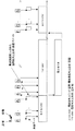
アレーアンテナ1で受信された信号は,移相器2で送受信ビーム方向を目標より上方にむけるビームステアリングのための位相が与えられ,合成器3で電力合成されビーム形成される.合成器によるビーム形成された信号は周波数変換装置で,RF信号からベースバンド信号に周波数変換される.ベースバンド信号はA/D変換機5でデジタル化されたデジタル信号が得られる.複数の周波数を利用する周波数ダイバーシティ法である.図13は送信周波数を変えることでフェージングが発生する距離が変わること説明する図である.上図は,ある送信周波数f0に対しf0+10%の周波数,下図はf0−10%の周波数を用いたときの相対受信電力の距離依存性である.このように周波数を変えることで,ある位置にいる目標に対し受信電力が得られる周波数が存在することが分かる.複数の周波数を用いる周波数の制御方法は,図14のタイミングチャートで示すよに,送信パルス毎にf1,f2,・・と周波数を変える周波数ホッピング法(frequency hopping)と,送受信系が十分な帯域をもつ場合は,一つのパルス内でf1+f2+・・fkという複数の周波数を多重化して送信する周波数多重法がある.周波数ホッピングは,予め定められた周波数の順で順次送信するものであるが,その類似方式として周波数アジリティ法があり,受信電力が得られる周波数となるまでランダムに周波数を変更する方式である. 周波数多重は送受信系に広い帯域が必要となるため,複数の周波数を用いる従来法としては,周波数ホッピングが用いられている.
【0005】
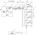
図15は第二の従来法の一例として,周波数ホッピングを用いたアンテナ装置の構成を説明する図であり,1〜7は図12と同じものであり,8は電力算出装置,9は電力加算器である.電力算出装置8では,各パルス毎に,各周波数f1,f2,・・fkで送信した信号を,個別に電力を算出する.電力加算器9では,各周波数各周波数f1,f2,・・fkで送信した信号電力をそのまま全て加算する.周波数によっては,フェージングが発生しない,パルスが含まれるため,全て加算した信号はフェージングが緩和されることが期待される.
【0006】
【発明が解決しようとする課題】
上記の第一の従来法におけるアンテナ装置は,ビーム指向性により直接波と海面反射波の到来角度差から受信電力を得る方法である.しかし,目標高度が低く距離が遠いと直接波と海面反射波の角度差は僅少となり,ビーム指向性の差ではフェージング対策として不十分である.
【0007】
一方,複数の周波数を用いる,第二の従来法では,ある周波数で得られた信号の電力を求め,電力が得られる周波数を選択する(周波数アジリティ法),あるいは予め定められた周波数で送信したパルスの受信信号電力を全て加算する方法(周波数ホッピング)である.周波数を変更すればフェージングが発生する距離が変化することは前記したが,直接波と海面反射波の路長差と海面反射時の位相シフトの関係によっては,複数の周波数を用いてもいずれの周波数においても電力が得られないという状況も発生しうる.このように,複数の周波数を利用し,各周波数で電力を求めた後に加算する従来法2でもフェージング対策として十分でないという問題がある.
【0008】
この発明は、上記のような課題を解決するためになされたものであり,フェージング対策を行うものであり,この中で,単一の周波数のみを用いる解決法と,複数の周波数を用いる解決法とを示す.
【0009】
【課題を解決するための手段】
第1の発明は,レーダパルスを送受信するアレーアンテナと,前記アレーアンテナにより送受信された信号の振幅・位相を制御する移相器と,前記位相器の出力信号を電圧合成する合成器と,前記合成器の出力信号を周波数変換する周波数変換装置と,前記周波数変換装置の出力信号を最大S/N(Signal to Noise ratio)で合成するためのウエイトを推定する空間最大比合成ウエイト推定装置と,前記空間最大比合成ウエイト推定装置により推定されたウエイトに従い前記周波数変換装置の出力信号を合成する空間最大比合成装置とを備えるアンテナ装置である.
【0010】
【発明の実施の形態】
実施の形態1.
図1はこの第一発明の実施の形態を示すもので、図において、1〜7は従来法と同じである.10は空間最大比合成ウエイト推定装置,11は空間最大比合成装置である.
【0011】
アレーアンテナ1で送信した周波数f1の送信パルスは,目標から反射し同じくアレーアンテナ1に入射し受信信号となる.アレー素子数をN,サブアレー数をM(図1では一例としてM=4としている.),サブアレー内の素子数をNsとする.アレーアンテナに入力する受信信号のうち目標が含まれる受信信号(サンプル数をTとする.)を行列形式でXr∈CN × Tとする.ここで,CN × Tは,複素数を要素としたN行T列の行列であることを表す.受信信号Xrは,位相器2に入力される.移相器2では,送信方向と同じ方向に受信ビーム指向する各サブアレー別のビームステアリング操作を行う.ここで,ステアリングベクトルをB(θ) ∈CN × Tと書く.合成器3では,サブアレーの出力信号として,“数1”が得られる.
【0012】
【数1】

ここで,アレーアンテナ1がリニアアレーの場合を例とすると,B(θ) ∈CN × Tは,“数2”となる
【0014】
【数2】
ここで,行列の右肩のTは転置行列を表し,θは電波の入射角,dはアレーアンテナの各アンテナの間隔,λは送信波の波長を示す.また,合成器3の出力は,“数3”となる.
【0016】
【数3】
ここで,submatrix(X,a:b,c:d)は,マトリックスの〜行,〜d列のサブマトリックスを切り出す操作を表す.第一の発明では,“数3”で書かれる合成器出力信号は,ベースバンドへ周波数変換されA/D変換された後,空間最大比合成装置10に入力される.空間最大比合成装置では,合成器3出力であるサブアレー間の信号に最大比合成が適用される.空間最大比合成について説明する.各サブアレーの出力Ymを一つの行列に纏めて,空間最大比合成への入力データ行列Z ∈CN × Tを,“数4”と記述する.
【0018】
【数4】
このデータ行列を用いて空間最大比合成ウエイト推定装置11では,空間最大比合成ウエイトを求めるために,zに関する相関行列_Rを,“数5”で求める.
【0020】
【数5】
![]()
さらに,相関行列Rの最大固有値に対応する固有ベクトルW1を求めることで,空間最大比合成のウエイトベクトルが得られる.こうして得られた空間最大比合成ウエイトは,空間最大比合成装置10に入力され,空間最大比合成装置ではこのウエイトベクトルを用い図2のタイミング図に示すように,目標の有無に関わらず送信パルスと送信パルス間の全ての距離サンプルrに亙り“数6”の処理を行う.
【0022】
【数6】
![]()
次に,電力P(r)は,“数7”となる.
【0024】
【数7】
サブアレー構成による空間最大比合成装置の動作である.空間最大比合成によりフェージング対策が図られたS/Nの良い信号が得られる.一般的には,この空間最大比合成装置の出力は,距離方向に 閾値処理が適用され目標検出が検出される.また,S/Nが向上したことにより目標検出サンプルの区間の中で,より正確な距離の測定が可能となる.また,サブアレー構成とすることで,数5の相関行列の固有ベクトル計算などの次元が削減され,計算量が著しく低減されている.この実施の形態1では,図2に示すように各送信パルスに対し以上を繰り返す.
【0026】
単一の周波数を用いれば、アレーアンテナをサブアレー構成とする方法を採用しているため,マルチパス環境で空間最大比合成を採用しフェージングによる受信信号の消滅を回避する上で,送受信系ハードウエアの削減,空間最大比合成ウエイト計算負荷低減を可能とする効果がある.図3は,単一の周波数を用いる受信空間最大比合成,および送受信空間最大比合成の効果を示す図である.図3の(a)は,目標高度を一定として横軸は目標までの距離であり,縦軸は受信相対電力である.実線は,フルDBF(Degital Beam forminng:サブアレー構成でなく,各放射素子での受信信号をベースバンドまで周波数変換し最大比合成したもの.)による受信空間最大比合成法で得られる受信電力である.点線は,同じく送受信空間最大比合成法,破線は参考としてのモノパルス和信号,一点鎖線は同じく参考としてのマルチパスのない自由空間でのモノパルス和信号である.図3は,目標高度が低く,遠方にある場合であり,直接波と海面反射波の角度がほとんど0であるため空間最大比合成は,自由空間でもノモパルス和信号とう同等となるレベルまでの電力回復は得られていない.しかし,角度差が大きかったり(すなわち目標高度がもう少し高い場合),アレーアンテナの開口径が大きければ,図中の近距離で見られるように空間最大比合成法でも電力回復が期待できる.図3の(b)(c)は,サブアレー構成による空間最大比合成の効果を説明する図である.
図3(b)はフルDBFに比べた2サブアレー構成での利得低下を,(c)は同様にフルDBFに比べた4サブアレー構成での利得低下の例を示す.いずれも,フルDBFに比べ利得の低下は少なく,第一の発明によるサブアレー構成での空間最大比合成でも十分満足する効果が得られることが可能である.
【0027】
実施の形態2.
実施の形態2は,構成は図1と同じであるが,図4のタイミング図に示すように受信信号から得られた空間最大比合成ウエイトを,つぎの送信波の送信ウエイトとして用いることを特徴としており,送信と受信双方で空間最大比合成を実現するものである.
【0028】
実施の形態3.
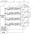
実施の形態3は第二の発明(周波数ホッピング空間・周波数最大比合成)の実施例である.図5はこの実施の形態を示すもので、図において、1〜7は従来法と同じである.12は空間・周波数最大比合成ウエイト推定装置,13は空間・周波数最大比合成装置である.第二の発明では,第一の発明と同様にサブアレー構成によりパルス毎に周波数ホッピングを行い送信したときの受信パルスデータを保持しておいて,空間・周波数最大比合成法を実現する方法である.
【0029】
図6は,この実施の形態3の,送受信および処理タイミングを説明する図である.図6に示すように,送信パルスの周波数をf1,f2・・・fxとパルス毎で変更し送信する.この間,各送信パルスの目標反射からのアレーアンテナに入力する受信信号は,第一の発明と同様に,位相器2で送信方向と同じ方向に受信ビーム指向する各サブアレー別のビームステアリング操作される.周波数番号をとすると,サブアレー番号での合成器3出力は,式(1)と同様にYm,k∈C1 × Tが得られる.空間・周波数最大比合成装置12では,このYm,k∈C1 × Tを,全ての周波数での送受信が完了するまで保持しておく.次に,これらを列方向にならべて行列V∈CMK × T作成する.
【0030】
数8”で定義した次元の列ベクトルに対し,空間最大比合成と同じ数(5)〜(7)の処理を行う.こうして,各周波数,および各サブアレーで得られた受信信号の最大比合成が容易に実現可能となる
【0031】
【数8】
実施の形態4.
実施の形態4は第二の発明(周波数ホッピング空間・周波数最大比合成)の別の実施例である.図7は,この実施の形態4の,送受信および処理タイミングを説明する図である.実施の形態4は,実施の形態2と3を組み合せたものである.実施の形態3による周波数ホッピングした送信パルス列を送信する.そのパルス列から空間・周波数最大比合成ウエイト推定装置で推定したウエイトを受信の空間・周波数最大比合成に持ちいるのみにならず,次の送信パルスは空間・周波数最大比合成ウエイトの要素のうち振幅の大きな要素に対応する周波数と,その要素を送信ウエイトとして用いるものである.続く送受信は,実施の形態2を繰り返しつつ,電力をモニタすることで,空間最大比合成だけでは,フェージングによる受信電力の回復が困難となり周波数を変更すべきかを判断する.周波数を変更すべきと判断された場合は,次の送信パルスとして実施の形態4の初めと同様に周波数ホッピングした送信パルス列を送信する実施の形態3を実施するものである.以下,同様の制御を繰り返す.このように制御することで,実施の形態2にくらべ周波数ホッピングを併用しているためフェージング改善効果が大きく,かつ周波数ホッピングした送信を繰り返す実施の形態3に比べ,実施の形態2の空間周波数最大比合成で十分な場合は,それを,繰り返すことになり,全体としての電力利用効率を向上させることが可能である.
【0033】
実施の形態5.
実施の形態5は,第三の発明(周波数多重空間・周波数最大比合成)の実施例である.図8この実施の形態を示すもので、図において、1〜7は図5の実施の形態3と同じである.12は空間・周波数最大比合成ウエイト推定装置,13は空間・周波数最大比合成装置である.14は周波数多重して送信されたパルスの受信信号を各周波数に弁別する周波数弁別装置である.第三の発明は,空間・周波数最大比合成ウエイト推定装置,空間・周波数最大比合成装置の機能としては,第二の発明と同様である.図9を用いて実施の形態5(すなわち第三の発明)を説明する.図9は送受信および処理タイミングを説明する図である.実施の形態5では,実施の形態3で各送信パルスを周波数ホッピングした周波数を同時に一つの送信パルスで周波数多重化して送信するものである.送受信系が広い帯域をもち,複数の周波数を同時に送信可能な場合に適用可能となる.周波数弁別により各周波数に弁別された各サブアレーの信号を,空間・周波数最大比合成ウエイト推定装置12にて,第二の発明と同じ数(8)を作成する.第二の発明と同様にして得られた空間・最大比合成ウエイトを用いて,空間・周波数最大比合成装置13にて受信信号を合成する.こうして,各周波数,および各サブアレーで得られた受信信号の最大比合成が1パルスにて容易に実現可能となる.更に,この空間・周波数最大比合成ウエイトを,送信機7,位相器2に入力し,次の送信時の周波数多重パルスのウエイトとして用いることで送信の空間・周波数最大比合成が可能となる.これを繰り返すことで,送受信の空間・周波数最大比合成が実現可能となる.
【0034】
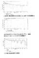
図10は,複数の周波数を利用する第二の発明の効果を説明する図である.図10(a)は,図3(a)と同様の図であり,実線は周波数ホッピングを用いたときのフルDBFによる空間・周波数最大比合成による受信電力である.周波数は,中心周波数をf0(=6GHz)として,f0−10%,f0,f0+10%の3種を用いた例である.点線は参考としてのモノパルス和信号,一点鎖線は同じく参考としてのマルチパスのない自由空間でのモノパルス和信号である.この図から,空間・周波数最大比合成により全ての距離範囲において自由空間でのモノパルス和信号以上の受信電力が得られることが確認される.同様に,図10(b)は,周波数ホッピング空間・周波数最大比合成,または周波数多重空間・周波数最大比合成であるサブアレー構成による空間・周波数最大比合成の効果を説明する図である.図10(b)は,フルDBFに比べた2および4サブアレーでの利得の低下と,従来の第二の方法(周波数ホッピングしたパスルの各電力を加算する方法.ノンコヒーレントF/Hと呼ぶ.)での利得の低下を説明する図である.2,および4サブアレーでもフルDBFに比べて利得の低下は,2dB以下に止まっているが,第二の従来法(ノンコヒーレントF/H)では,近距離で10dB近いフェージングが発生している.この理由は,図10(c) は,3種の各周波数での受信電力を示す.図10(c)から明らかなように,使用した3種の周波数のいずれにおいても電力のヌルとなる距離が一致してしまったため,第二の従来法ではフェージングによる電力の消滅を回避しきれないことが分かる.このように,空間・周波数最大比合成によりこのような悪条件下でも自由空間でのモノパルス和信号以上の電力が得られるという効果が得られる.
【0035】
【発明の効果】
上記によりフェージング対策を行うことができる.
【図面の簡単な説明】
【図1】実施の形態1および2を示すアンテナ装置のブロック図である.
【図2】実施の形態1の動作タイミングを説明する図である.
【図3】実施の形態1および2の効果を説明する図である
【図4】実施の形態2の動作タイミングを説明する図である.
【図5】実施の形態3および4を示すアンテナ装置のブロック図である.
【図6】実施の形態3の動作タイミングを説明する図である.
【図7】実施の形態4の動作タイミングを説明する図である.
【図8】実施の形態5を示すアンテナ装置のブロック図である.
【図9】実施の形態5の動作タイミングを説明する図である.
【図10】実施の形態4または5の効果を説明する図である.
【図11】マルチパス環境の電波伝播を説明する図である.
【図12】従来の第一の技術によるアンテナ装置のブロック図である.
【図13】マルチパス環境での受信電力の周波数依存性を説明する図である.
【図14】周波数ホッピング送信と周波数多重送信のタイミングを説明する図である.
【図15】従来の第二の技術によるアンテナ装置のブロック図である.
【符号の説明】
1 アレーアンテナ,2 移相器,3 合成器,4 周波数変換装置,5A/D変換機,6 ビーム形成器,7 送信機,8 電力算出器,9 電力加算器,10 空間最大比合成ウエイト推定装置,11 空間最大比合成装置,12 空間・周波数最大比合成ウエイト推定装置,13 空間・周波数最大比合成装置,14 目標[0001]
TECHNICAL FIELD OF THE INVENTION
The present invention provides a radar for avoiding a phenomenon in which when a low-altitude target is tracked in a tracking radar or an air traffic control radar, a received signal disappears due to a multipath phenomenon caused by a direct wave and sea surface reflection (or ground reflection), making target tracking difficult. It is related to fading countermeasure technology.
[0002]
[Prior art]
Figure 11 shows a diagram explaining the multipath environment when tracking a low altitude target. In such a situation, the direct wave and the sea surface reflected wave have a small angle difference in the same beam. On the other hand, the Doppler frequency difference and the time delay difference are almost negligible (not observable). In other words, the direct wave and the sea surface reflected wave are in a situation close to a perfect correlation signal shifted only in phase. In such a multipath environment, depending on the target position (distance / altitude), fading occurs in which the power disappears due to the multipath phenomenon. In such a multipath environment, there is a method to reduce fading by directing the transmitting and receiving beam directions above the target. However, only the signal of the beam gain difference between the direct wave and the sea surface reflected wave method is obtained, which is not enough as a countermeasure for fading.
[0003]
A spatial diversity method is known as a fading countermeasure using an array antenna. The spatial diversity method includes a selection method for simply selecting an antenna having the best reception state among array antennas, an equal gain combining method, and a maximum ratio combining method (MRC). The maximum ratio combining method is the most efficient spatial diversity method in which the phases of the signals obtained by each element of the array antenna are aligned and weighted by S / N. Countermeasures against fading using the maximum ratio combining method are described in [1] Yoshio Karasawa, Takashi Inoue, Yukihiro Kamiya, Satoshi Tano, "Software Antenna [2]," IEICE Technical Report, RCS 98-152, pp7-12, Nov . 1998. [2] Yukihiro Kamiya, Yoshio Karasawa, "Software Antenna [3]," IEICE Technical Report, AP-98-139, pp65-72, Jan. 1998. [3] Yoshio Karasawa, "Basic Study on Road Reflection Fading and Space Diversity in ITS Millimeter-Wave Inter-Vehicle Communication," IEICE B, vol. J83-B, No. 4, pp. 518-524, April, 2000. Reported in. FIG. 12 is a diagram illustrating the configuration of these conventional antenna devices that apply the maximum ratio combining method to the signal received by the array antenna. In FIG. 12, 1 is an array antenna, 2 is a phase shifter, 3 is a combiner, 4 is a frequency converter, 5 is an A / D converter, 6 is a beam forming device, and 7 is a transmitter.
[0004]
The signal received by the
[0005]
FIG. 15 is a diagram for explaining the configuration of an antenna device using frequency hopping as an example of a second conventional method, wherein 1 to 7 are the same as those in FIG. 12, 8 is a power calculation device, and 9 is a power addition device. Container. The
[0006]
[Problems to be solved by the invention]
The antenna device in the first conventional method is a method to obtain the received power from the arrival angle difference between the direct wave and the sea surface reflected wave by the beam directivity. However, if the target altitude is low and the distance is long, the angle difference between the direct wave and the sea surface reflected wave is small, and the difference in beam directivity is not enough as a countermeasure against fading.
[0007]
On the other hand, in the second conventional method that uses a plurality of frequencies, the power of a signal obtained at a certain frequency is obtained, and the frequency at which the power is obtained is selected (frequency agility method), or transmitted at a predetermined frequency. This is a method (frequency hopping) in which all received signal powers of pulses are added. As described above, if the frequency is changed, the distance at which fading occurs will change. However, depending on the relationship between the path length difference between the direct wave and the sea surface reflected wave and the phase shift at the time of sea surface reflection, any of a plurality of frequencies may be used. In some cases, power cannot be obtained even at frequencies. As described above, the
[0008]
SUMMARY OF THE INVENTION The present invention has been made to solve the above-described problems, and is a countermeasure for fading. Among them, a solution using only a single frequency and a solution using a plurality of frequencies. Is shown.
[0009]
[Means for Solving the Problems]
A first invention provides an array antenna for transmitting and receiving radar pulses, a phase shifter for controlling the amplitude and phase of a signal transmitted and received by the array antenna, a combiner for voltage-synthesizing an output signal of the phase shifter, A frequency converter for frequency-converting the output signal of the synthesizer, a spatial maximum ratio combined weight estimator for estimating a weight for synthesizing the output signal of the frequency converter with a maximum signal-to-noise ratio (S / N), An antenna device comprising: a spatial maximum ratio combining device that combines output signals of the frequency conversion device according to the weight estimated by the spatial maximum ratio combining weight estimating device.
[0010]
BEST MODE FOR CARRYING OUT THE INVENTION
FIG. 1 shows an embodiment of the first invention, in which 1 to 7 are the same as in the conventional method.
[0011]
The transmission pulse of the frequency f1 transmitted by the
[0012]
(Equation 1)
Here, if the case where the
(Equation 2)
Here, T on the right shoulder of the matrix represents the transposed matrix, θ is the incident angle of the radio wave, d is the distance between the array antennas, and λ is the wavelength of the transmitted wave. The output of the
[0016]
[Equation 3]
Here, submatrix (X, a: b, c: d) represents an operation of cutting out a sub-matrix of ~ row and ~ d column of the matrix. In the first invention, the synthesizer output signal written by "
[0018]
(Equation 4)
Using this data matrix, the spatial maximum ratio composite
[0020]
(Equation 5)
![]()
Further, a weight vector for spatial maximum ratio combining is obtained by obtaining an eigenvector W1 corresponding to the maximum eigenvalue of the correlation matrix R. The spatial maximum ratio combining weight thus obtained is input to the spatial maximum
[0022]
(Equation 6)
![]()
Next, the power P (r) becomes “
[0024]
(Equation 7)
This is the operation of the spatial maximum ratio synthesizer using a sub-array configuration. A signal with good S / N ratio with fading countermeasures achieved by spatial maximum ratio combining is obtained. Generally, threshold detection is applied to the output of this spatial maximum ratio synthesizer in the distance direction, and target detection is detected. In addition, the improved S / N allows more accurate distance measurement in the section of the target detection sample. In addition, by using a sub-array configuration, dimensions such as eigenvector calculation of the correlation matrix of
[0026]
If a single frequency is used, the method of using a sub-array configuration of the array antenna is adopted. Therefore, in order to avoid the disappearance of the received signal due to fading by adopting spatial maximum ratio combining in a multipath environment, the transmission / reception hardware This has the effect of reducing the load and reducing the computational load on the spatial maximum ratio composite weight. Fig. 3 is a diagram showing the effects of maximum ratio combining of the receiving space and maximum ratio combining of the transmitting and receiving spaces using a single frequency. In FIG. 3A, the horizontal axis is the distance to the target while the target altitude is constant, and the vertical axis is the received relative power. The solid line is the reception power obtained by the reception space maximum ratio combining method using a full DBF (Digital Beam forming: not a sub-array configuration, but a signal obtained by frequency-converting a received signal from each radiating element to baseband and performing maximum ratio combining). . The dotted line is the transmission / reception space maximum ratio combining method, the broken line is the reference monopulse sum signal, and the dashed line is the reference monopulse sum signal in free space without multipath. Fig. 3 shows the case where the target altitude is low and the distance is far, and the angle between the direct wave and the sea surface reflected wave is almost 0. No recovery has been obtained. However, if the angle difference is large (that is, the target altitude is slightly higher) or if the aperture diameter of the array antenna is large, power recovery can be expected even with the spatial maximum ratio combining method as seen at a short distance in the figure. FIGS. 3B and 3C are diagrams illustrating the effect of spatial maximum ratio combining by the sub-array configuration.
FIG. 3B shows an example of the gain reduction in the 2-subarray configuration compared to the full DBF, and FIG. 3C shows an example of the gain reduction in the 4-subarray configuration similarly to the full DBF. In each case, the reduction of the gain is smaller than that of the full DBF, and it is possible to obtain a sufficiently satisfactory effect even in the spatial maximum ratio combining in the sub-array configuration according to the first invention.
[0027]
[0028]
[0029]
FIG. 6 is a diagram for explaining transmission / reception and processing timing according to the third embodiment. As shown in FIG. 6, the frequency of the transmission pulse is changed to f1, f2,. During this time, the received signal input to the array antenna from the target reflection of each transmission pulse is subjected to beam steering operation for each sub-array for directing the reception beam in the same direction as the transmission direction by the
[0030]
The same number of processes (5) to (7) as in the spatial maximum ratio combining are performed on the column vector of the dimension defined by
(Equation 8)
[0033]
[0034]
FIG. 10 is a diagram illustrating the effect of the second invention using a plurality of frequencies. FIG. 10 (a) is a diagram similar to FIG. 3 (a), and the solid line is the received power by spatial-frequency maximum ratio combining by full DBF when frequency hopping is used. The frequency is an example using three types of f0-10%, f0, and f0 + 10% with the center frequency f0 (= 6 GHz). The dotted line is the monopulse sum signal for reference, and the dashed line is the reference monopulse sum signal in free space without multipath. From this figure, it is confirmed that the received power equal to or higher than the monopulse sum signal in free space can be obtained in the entire range of distances by spatial-frequency maximum ratio combining. Similarly, FIG. 10B is a diagram for explaining the effect of space / frequency maximum ratio combining using a sub-array configuration that is frequency hopping space / frequency maximum ratio combining or frequency multiplexing space / frequency maximum ratio combining. FIG. 10 (b) shows a reduction in gain in the 2 and 4 sub-arrays compared to the full DBF, and a second conventional method (a method of adding each power of a frequency-hopped pulse; referred to as non-coherent F / H). It is a figure explaining the fall of the gain in (). In the 2 and 4 sub-arrays, the decrease in the gain is less than 2 dB compared to the full DBF, but in the second conventional method (non-coherent F / H), fading close to 10 dB occurs at a short distance. The reason for this is that Fig. 10 (c) shows the received power at each of the three frequencies. As is clear from FIG. 10 (c), since the null distance of the power coincides with any of the three frequencies used, the disappearance of the power due to fading cannot be avoided in the second conventional method. You can see that. In this way, the effect that the power more than the monopulse sum signal in free space can be obtained even in such a bad condition by the space-frequency maximum ratio combination is obtained.
[0035]
【The invention's effect】
As a result, fading countermeasures can be taken.
[Brief description of the drawings]
FIG. 1 is a block diagram of an antenna device according to first and second embodiments.
FIG. 2 is a diagram for explaining the operation timing of the first embodiment.
FIG. 3 is a diagram illustrating effects of the first and second embodiments. FIG. 4 is a diagram illustrating operation timings of the second embodiment.
FIG. 5 is a block diagram of an antenna device according to the third and fourth embodiments.
FIG. 6 is a diagram for explaining the operation timing of the third embodiment.
FIG. 7 is a diagram for explaining the operation timing of the fourth embodiment.
FIG. 8 is a block diagram of an antenna device according to a fifth embodiment.
FIG. 9 is a diagram for explaining the operation timing of the fifth embodiment.
FIG. 10 is a diagram illustrating the effect of the fourth or fifth embodiment.
FIG. 11 is a diagram illustrating radio wave propagation in a multipath environment.
FIG. 12 is a block diagram of an antenna device according to a first conventional technique.
FIG. 13 is a diagram illustrating the frequency dependence of received power in a multipath environment.
FIG. 14 is a diagram illustrating timings of frequency hopping transmission and frequency multiplex transmission.
FIG. 15 is a block diagram of an antenna device according to a second conventional technique.
[Explanation of symbols]
Claims (5)
前記アレーアンテナにより送受信された信号の振幅・位相を制御する移相器と,前記位相器の出力信号を電圧合成する合成器と,
前記合成器の出力信号を周波数変換する周波数変換装置と,
前記周波数変換装置の出力信号を最大S/N(Signal to Noise ratio)で合成するためのウエイトを推定する空間最大比合成ウエイト推定装置と,
前記空間最大比合成ウエイト推定装置により推定されたウエイトに従い前記周波数変換装置の出力信号を合成する空間最大比合成装置と,
を備えるアンテナ装置.An array antenna for transmitting and receiving radar pulses,
A phase shifter for controlling the amplitude and phase of a signal transmitted and received by the array antenna, a synthesizer for voltage-synthesizing an output signal of the phase shifter,
A frequency converter for frequency-converting the output signal of the synthesizer;
A spatial maximum ratio combining weight estimating apparatus for estimating a weight for combining output signals of the frequency converting apparatus with a maximum signal-to-noise ratio (S / N);
A spatial maximum ratio synthesizing device that synthesizes an output signal of the frequency conversion device according to the weight estimated by the spatial maximum ratio combining weight estimating device;
An antenna device comprising:
を備える請求項1に記載のアンテナ装置.A transmitter for transmitting a radar pulse based on the weight estimated by the spatial maximum ratio combined weight estimating device;
The antenna device according to claim 1, further comprising:
前記アレーアンテナにより送受信された信号の振幅・位相を制御する移相器と,前記位相器の出力信号を電圧合成する合成器と,
前記合成器の出力信号を周波数変換する周波数変換装置と,
前記周波数変換装置の周波数ホッピングされた出力信号を最大S/N(Signal to Noise ratio)で合成するためのウエイトを推定する空間・周波数最大比合成ウエイト推定装置と,
前記空間・周波数最大比合成ウエイト推定装置により推定されたウエイトに従い前記周波数変換装置の出力信号を合成する空間・周波数最大比合成装置と,
を備えるアンテナ装置.An array antenna for transmitting and receiving radar pulses,
A phase shifter for controlling the amplitude and phase of a signal transmitted and received by the array antenna, a synthesizer for voltage-synthesizing an output signal of the phase shifter,
A frequency converter for frequency-converting the output signal of the synthesizer;
A space / frequency maximum ratio combining weight estimating apparatus for estimating a weight for combining a frequency-hopped output signal of the frequency converting apparatus with a maximum signal-to-noise ratio (S / N);
A space / frequency maximum ratio combining device that combines output signals of the frequency conversion device according to the weight estimated by the space / frequency maximum ratio combining weight estimating device;
An antenna device comprising:
前記アレーアンテナにより送受信された信号の振幅・位相を制御する移相器と,前記位相器の出力信号を電圧合成する合成器と,
前記合成器の出力信号の周波数多重信号を各周波数に弁別する周波数弁別装置と,
前記周波数弁別装置の出力信号を周波数変換する周波数変換装置と,
前記周波数変換装置の出力信号を最大S/N(Signal to Noise ratio)で合成するためのウエイトを推定する空間・周波数最大比合成ウエイト推定装置と,
前記空間・周波数最大比合成ウエイト推定装置により推定されたウエイトに従い前記周波数変換装置の出力信号を合成する空間・周波数最大比合成装置と,
を備えるアンテナ装置.An array antenna for transmitting and receiving radar pulses,
A phase shifter for controlling the amplitude and phase of a signal transmitted and received by the array antenna, a synthesizer for voltage-synthesizing an output signal of the phase shifter,
A frequency discriminator for discriminating a frequency multiplexed signal of the output signal of the synthesizer into respective frequencies;
A frequency converter for frequency-converting an output signal of the frequency discriminator;
A space / frequency maximum ratio combining weight estimating apparatus for estimating a weight for combining an output signal of the frequency converting apparatus with a maximum signal to noise ratio (S / N);
A space / frequency maximum ratio combining device that combines output signals of the frequency conversion device according to the weight estimated by the space / frequency maximum ratio combining weight estimating device;
An antenna device comprising:
Priority Applications (1)
| Application Number | Priority Date | Filing Date | Title |
|---|---|---|---|
| JP2002282692A JP3861785B2 (en) | 2002-09-27 | 2002-09-27 | Antenna device |
Applications Claiming Priority (1)
| Application Number | Priority Date | Filing Date | Title |
|---|---|---|---|
| JP2002282692A JP3861785B2 (en) | 2002-09-27 | 2002-09-27 | Antenna device |
Publications (2)
| Publication Number | Publication Date |
|---|---|
| JP2004117246A true JP2004117246A (en) | 2004-04-15 |
| JP3861785B2 JP3861785B2 (en) | 2006-12-20 |
Family
ID=32276777
Family Applications (1)
| Application Number | Title | Priority Date | Filing Date |
|---|---|---|---|
| JP2002282692A Expired - Fee Related JP3861785B2 (en) | 2002-09-27 | 2002-09-27 | Antenna device |
Country Status (1)
| Country | Link |
|---|---|
| JP (1) | JP3861785B2 (en) |
Cited By (11)
| Publication number | Priority date | Publication date | Assignee | Title |
|---|---|---|---|---|
| JP2008164483A (en) * | 2006-12-28 | 2008-07-17 | Mitsubishi Electric Corp | Array antenna and its beam control method |
| JP2008196921A (en) * | 2007-02-09 | 2008-08-28 | Toshiba Corp | Weight calculation method, weight calculation device, adaptive array antenna, and radar device |
| JP2010249535A (en) * | 2009-04-10 | 2010-11-04 | Mitsubishi Electric Corp | Radar device |
| JP2011182144A (en) * | 2010-02-26 | 2011-09-15 | Mitsubishi Heavy Ind Ltd | Phased array antenna and control method thereof |
| JP2012189474A (en) * | 2011-03-11 | 2012-10-04 | Nec Corp | Radar apparatus, data processing method and data processing program |
| JP2014163929A (en) * | 2013-02-27 | 2014-09-08 | Mitsubishi Electric Corp | Method of acquiring and processing signal received by array of sensing elements and system of acquiring and processing signal |
| JP2015514970A (en) * | 2012-02-22 | 2015-05-21 | トヨタ モーター エンジニアリング アンド マニュファクチャリング ノース アメリカ,インコーポレイティド | Hybrid radar integrated in a single package |
| CN104833958A (en) * | 2015-04-03 | 2015-08-12 | 西北大学 | Mobile sensor array AOA detection sum-difference algorithm |
| JP2017181177A (en) * | 2016-03-29 | 2017-10-05 | 瀚誼世界科技股▲フン▼有限公司 | Wireless device proximity detection method |
| JP2017227515A (en) * | 2016-06-22 | 2017-12-28 | 日本電気株式会社 | Active sonar and control method for the same |
| JP2022550634A (en) * | 2019-12-10 | 2022-12-02 | レイセオン カンパニー | System and method for multipath beam nulling |
-
2002
- 2002-09-27 JP JP2002282692A patent/JP3861785B2/en not_active Expired - Fee Related
Cited By (11)
| Publication number | Priority date | Publication date | Assignee | Title |
|---|---|---|---|---|
| JP2008164483A (en) * | 2006-12-28 | 2008-07-17 | Mitsubishi Electric Corp | Array antenna and its beam control method |
| JP2008196921A (en) * | 2007-02-09 | 2008-08-28 | Toshiba Corp | Weight calculation method, weight calculation device, adaptive array antenna, and radar device |
| JP2010249535A (en) * | 2009-04-10 | 2010-11-04 | Mitsubishi Electric Corp | Radar device |
| JP2011182144A (en) * | 2010-02-26 | 2011-09-15 | Mitsubishi Heavy Ind Ltd | Phased array antenna and control method thereof |
| JP2012189474A (en) * | 2011-03-11 | 2012-10-04 | Nec Corp | Radar apparatus, data processing method and data processing program |
| JP2015514970A (en) * | 2012-02-22 | 2015-05-21 | トヨタ モーター エンジニアリング アンド マニュファクチャリング ノース アメリカ,インコーポレイティド | Hybrid radar integrated in a single package |
| JP2014163929A (en) * | 2013-02-27 | 2014-09-08 | Mitsubishi Electric Corp | Method of acquiring and processing signal received by array of sensing elements and system of acquiring and processing signal |
| CN104833958A (en) * | 2015-04-03 | 2015-08-12 | 西北大学 | Mobile sensor array AOA detection sum-difference algorithm |
| JP2017181177A (en) * | 2016-03-29 | 2017-10-05 | 瀚誼世界科技股▲フン▼有限公司 | Wireless device proximity detection method |
| JP2017227515A (en) * | 2016-06-22 | 2017-12-28 | 日本電気株式会社 | Active sonar and control method for the same |
| JP2022550634A (en) * | 2019-12-10 | 2022-12-02 | レイセオン カンパニー | System and method for multipath beam nulling |
Also Published As
| Publication number | Publication date |
|---|---|
| JP3861785B2 (en) | 2006-12-20 |
Similar Documents
| Publication | Publication Date | Title |
|---|---|---|
| JP3872953B2 (en) | Wireless communication device using adaptive antenna | |
| US7737879B2 (en) | Split aperture array for increased short range target coverage | |
| EP2031415B1 (en) | Switchable antenna array for estimating the direction of arrival of a received signal | |
| US7423578B1 (en) | Split aperture array for increased short range target coverage | |
| Colone et al. | Space–time constant modulus algorithm for multipath removal on the reference signal exploited by passive bistatic radar | |
| EP2556385B1 (en) | Electronic counter measure system | |
| Frazer et al. | Spatially waveform diverse radar: Perspectives for high frequency OTHR | |
| Wu et al. | MIMO-OFDM radar for direction estimation | |
| Frazer et al. | Multiple-input multiple-output over-the-horizon radar: experimental results | |
| CN108226871B (en) | Diversity phased array design method based on millimeter wave collision avoidance radar | |
| Nusenu et al. | Frequency diverse array antennas: From their origin to their application in wireless communication systems | |
| CN113660017A (en) | SINR maximization method of IRS-assisted dual-function radar communication system | |
| EP3306745B1 (en) | Sensor device | |
| JP3861785B2 (en) | Antenna device | |
| Ahmad et al. | Beampattern analysis of frequency diverse array radar: a review | |
| Basit et al. | Adaptive transmit array sidelobe control using FDA-MIMO for tracking in joint radar-communications | |
| Basit et al. | Range-angle-dependent beampattern synthesis with null depth control for joint radar communication | |
| CN114114188A (en) | FDA radar communication integrated waveform design method with low side lobe | |
| US11662425B2 (en) | Digital radar imaging using 5G-NR millimeter wave base station antenna solutions | |
| WO2020189457A1 (en) | Radar device and transmitting/receiving array antenna | |
| Nusenu et al. | Cognitive transmit subarray FDA design for integrated radar-communication using flexible sidelobe control | |
| EP3757599A1 (en) | Fast spatial search using phased array antennas | |
| Weiß | Digital Antenna | |
| JP7361266B2 (en) | radar equipment | |
| Liu et al. | Full-Duplex Analog Beamforming Design for mm-Wave Integrated Sensing and Communication |
Legal Events
| Date | Code | Title | Description |
|---|---|---|---|
| RD01 | Notification of change of attorney |
Free format text: JAPANESE INTERMEDIATE CODE: A7421 Effective date: 20040708 |
|
| A621 | Written request for application examination |
Free format text: JAPANESE INTERMEDIATE CODE: A621 Effective date: 20040825 |
|
| A977 | Report on retrieval |
Free format text: JAPANESE INTERMEDIATE CODE: A971007 Effective date: 20051104 |
|
| A131 | Notification of reasons for refusal |
Free format text: JAPANESE INTERMEDIATE CODE: A131 Effective date: 20051129 |
|
| A521 | Written amendment |
Free format text: JAPANESE INTERMEDIATE CODE: A523 Effective date: 20060127 |
|
| A131 | Notification of reasons for refusal |
Free format text: JAPANESE INTERMEDIATE CODE: A131 Effective date: 20060523 |
|
| A521 | Written amendment |
Free format text: JAPANESE INTERMEDIATE CODE: A523 Effective date: 20060711 |
|
| TRDD | Decision of grant or rejection written | ||
| A01 | Written decision to grant a patent or to grant a registration (utility model) |
Free format text: JAPANESE INTERMEDIATE CODE: A01 Effective date: 20060905 |
|
| A61 | First payment of annual fees (during grant procedure) |
Free format text: JAPANESE INTERMEDIATE CODE: A61 Effective date: 20060918 |
|
| FPAY | Renewal fee payment (prs date is renewal date of database) |
Free format text: PAYMENT UNTIL: 20091006 Year of fee payment: 3 |
|
| FPAY | Renewal fee payment (prs date is renewal date of database) |
Free format text: PAYMENT UNTIL: 20101006 Year of fee payment: 4 |
|
| FPAY | Renewal fee payment (prs date is renewal date of database) |
Free format text: PAYMENT UNTIL: 20111006 Year of fee payment: 5 |
|
| FPAY | Renewal fee payment (prs date is renewal date of database) |
Free format text: PAYMENT UNTIL: 20121006 Year of fee payment: 6 |
|
| FPAY | Renewal fee payment (prs date is renewal date of database) |
Free format text: PAYMENT UNTIL: 20131006 Year of fee payment: 7 |
|
| LAPS | Cancellation because of no payment of annual fees |