JP2004116526A - Pressure limiting device, and fuel system with pressure limiting device - Google Patents
Pressure limiting device, and fuel system with pressure limiting device Download PDFInfo
- Publication number
- JP2004116526A JP2004116526A JP2003332145A JP2003332145A JP2004116526A JP 2004116526 A JP2004116526 A JP 2004116526A JP 2003332145 A JP2003332145 A JP 2003332145A JP 2003332145 A JP2003332145 A JP 2003332145A JP 2004116526 A JP2004116526 A JP 2004116526A
- Authority
- JP
- Japan
- Prior art keywords
- pressure
- limiting device
- fuel
- pressure limiting
- piston
- Prior art date
- Legal status (The legal status is an assumption and is not a legal conclusion. Google has not performed a legal analysis and makes no representation as to the accuracy of the status listed.)
- Withdrawn
Links
Images


Classifications
-
- F—MECHANICAL ENGINEERING; LIGHTING; HEATING; WEAPONS; BLASTING
- F02—COMBUSTION ENGINES; HOT-GAS OR COMBUSTION-PRODUCT ENGINE PLANTS
- F02M—SUPPLYING COMBUSTION ENGINES IN GENERAL WITH COMBUSTIBLE MIXTURES OR CONSTITUENTS THEREOF
- F02M63/00—Other fuel-injection apparatus having pertinent characteristics not provided for in groups F02M39/00 - F02M57/00 or F02M67/00; Details, component parts, or accessories of fuel-injection apparatus, not provided for in, or of interest apart from, the apparatus of groups F02M39/00 - F02M61/00 or F02M67/00; Combination of fuel pump with other devices, e.g. lubricating oil pump
- F02M63/02—Fuel-injection apparatus having several injectors fed by a common pumping element, or having several pumping elements feeding a common injector; Fuel-injection apparatus having provisions for cutting-out pumps, pumping elements, or injectors; Fuel-injection apparatus having provisions for variably interconnecting pumping elements and injectors alternatively
- F02M63/0225—Fuel-injection apparatus having a common rail feeding several injectors ; Means for varying pressure in common rails; Pumps feeding common rails
- F02M63/023—Means for varying pressure in common rails
- F02M63/0235—Means for varying pressure in common rails by bleeding fuel pressure
- F02M63/0245—Means for varying pressure in common rails by bleeding fuel pressure between the high pressure pump and the common rail
-
- F—MECHANICAL ENGINEERING; LIGHTING; HEATING; WEAPONS; BLASTING
- F02—COMBUSTION ENGINES; HOT-GAS OR COMBUSTION-PRODUCT ENGINE PLANTS
- F02M—SUPPLYING COMBUSTION ENGINES IN GENERAL WITH COMBUSTIBLE MIXTURES OR CONSTITUENTS THEREOF
- F02M55/00—Fuel-injection apparatus characterised by their fuel conduits or their venting means; Arrangements of conduits between fuel tank and pump F02M37/00
- F02M55/04—Means for damping vibrations or pressure fluctuations in injection pump inlets or outlets
-
- F—MECHANICAL ENGINEERING; LIGHTING; HEATING; WEAPONS; BLASTING
- F02—COMBUSTION ENGINES; HOT-GAS OR COMBUSTION-PRODUCT ENGINE PLANTS
- F02M—SUPPLYING COMBUSTION ENGINES IN GENERAL WITH COMBUSTIBLE MIXTURES OR CONSTITUENTS THEREOF
- F02M63/00—Other fuel-injection apparatus having pertinent characteristics not provided for in groups F02M39/00 - F02M57/00 or F02M67/00; Details, component parts, or accessories of fuel-injection apparatus, not provided for in, or of interest apart from, the apparatus of groups F02M39/00 - F02M61/00 or F02M67/00; Combination of fuel pump with other devices, e.g. lubricating oil pump
- F02M63/0012—Valves
- F02M63/0031—Valves characterized by the type of valves, e.g. special valve member details, valve seat details, valve housing details
- F02M63/005—Pressure relief valves
-
- F—MECHANICAL ENGINEERING; LIGHTING; HEATING; WEAPONS; BLASTING
- F02—COMBUSTION ENGINES; HOT-GAS OR COMBUSTION-PRODUCT ENGINE PLANTS
- F02M—SUPPLYING COMBUSTION ENGINES IN GENERAL WITH COMBUSTIBLE MIXTURES OR CONSTITUENTS THEREOF
- F02M63/00—Other fuel-injection apparatus having pertinent characteristics not provided for in groups F02M39/00 - F02M57/00 or F02M67/00; Details, component parts, or accessories of fuel-injection apparatus, not provided for in, or of interest apart from, the apparatus of groups F02M39/00 - F02M61/00 or F02M67/00; Combination of fuel pump with other devices, e.g. lubricating oil pump
- F02M63/02—Fuel-injection apparatus having several injectors fed by a common pumping element, or having several pumping elements feeding a common injector; Fuel-injection apparatus having provisions for cutting-out pumps, pumping elements, or injectors; Fuel-injection apparatus having provisions for variably interconnecting pumping elements and injectors alternatively
- F02M63/0225—Fuel-injection apparatus having a common rail feeding several injectors ; Means for varying pressure in common rails; Pumps feeding common rails
-
- F—MECHANICAL ENGINEERING; LIGHTING; HEATING; WEAPONS; BLASTING
- F02—COMBUSTION ENGINES; HOT-GAS OR COMBUSTION-PRODUCT ENGINE PLANTS
- F02M—SUPPLYING COMBUSTION ENGINES IN GENERAL WITH COMBUSTIBLE MIXTURES OR CONSTITUENTS THEREOF
- F02M2200/00—Details of fuel-injection apparatus, not otherwise provided for
- F02M2200/31—Fuel-injection apparatus having hydraulic pressure fluctuations damping elements
- F02M2200/315—Fuel-injection apparatus having hydraulic pressure fluctuations damping elements for damping fuel pressure fluctuations
-
- F—MECHANICAL ENGINEERING; LIGHTING; HEATING; WEAPONS; BLASTING
- F02—COMBUSTION ENGINES; HOT-GAS OR COMBUSTION-PRODUCT ENGINE PLANTS
- F02M—SUPPLYING COMBUSTION ENGINES IN GENERAL WITH COMBUSTIBLE MIXTURES OR CONSTITUENTS THEREOF
- F02M2200/00—Details of fuel-injection apparatus, not otherwise provided for
- F02M2200/40—Fuel-injection apparatus with fuel accumulators, e.g. a fuel injector having an integrated fuel accumulator
-
- F—MECHANICAL ENGINEERING; LIGHTING; HEATING; WEAPONS; BLASTING
- F02—COMBUSTION ENGINES; HOT-GAS OR COMBUSTION-PRODUCT ENGINE PLANTS
- F02M—SUPPLYING COMBUSTION ENGINES IN GENERAL WITH COMBUSTIBLE MIXTURES OR CONSTITUENTS THEREOF
- F02M63/00—Other fuel-injection apparatus having pertinent characteristics not provided for in groups F02M39/00 - F02M57/00 or F02M67/00; Details, component parts, or accessories of fuel-injection apparatus, not provided for in, or of interest apart from, the apparatus of groups F02M39/00 - F02M61/00 or F02M67/00; Combination of fuel pump with other devices, e.g. lubricating oil pump
- F02M63/0012—Valves
- F02M63/0031—Valves characterized by the type of valves, e.g. special valve member details, valve seat details, valve housing details
- F02M63/004—Sliding valves, e.g. spool valves, i.e. whereby the closing member has a sliding movement along a seat for opening and closing
-
- F—MECHANICAL ENGINEERING; LIGHTING; HEATING; WEAPONS; BLASTING
- F02—COMBUSTION ENGINES; HOT-GAS OR COMBUSTION-PRODUCT ENGINE PLANTS
- F02M—SUPPLYING COMBUSTION ENGINES IN GENERAL WITH COMBUSTIBLE MIXTURES OR CONSTITUENTS THEREOF
- F02M63/00—Other fuel-injection apparatus having pertinent characteristics not provided for in groups F02M39/00 - F02M57/00 or F02M67/00; Details, component parts, or accessories of fuel-injection apparatus, not provided for in, or of interest apart from, the apparatus of groups F02M39/00 - F02M61/00 or F02M67/00; Combination of fuel pump with other devices, e.g. lubricating oil pump
- F02M63/0012—Valves
- F02M63/0031—Valves characterized by the type of valves, e.g. special valve member details, valve seat details, valve housing details
- F02M63/0045—Three-way valves
Landscapes
- Engineering & Computer Science (AREA)
- Chemical & Material Sciences (AREA)
- Combustion & Propulsion (AREA)
- Mechanical Engineering (AREA)
- General Engineering & Computer Science (AREA)
- Fuel-Injection Apparatus (AREA)
- High-Pressure Fuel Injection Pump Control (AREA)
Abstract
Description
本発明は、内燃機関の燃料システムに用いられる、高圧燃料管路と低圧燃料管路との間に配置された圧力制限装置であって、ハウジングと、該ハウジングの孔内に案内されたピストンとが設けられており、該ピストンが、高圧燃料管路と低圧燃料管路との間に存在する規定された圧力差以降、高圧燃料管路と低圧燃料管路とを液圧的に接続するようになっており、孔とピストンとが、補償室を仕切っており、該補償室と高圧燃料管路との間に絞りが設けられている形式のものに関する。 The present invention relates to a pressure limiting device used for a fuel system of an internal combustion engine, which is disposed between a high-pressure fuel line and a low-pressure fuel line, comprising a housing, a piston guided into a hole of the housing, and Is provided so that the piston hydraulically connects the high-pressure fuel line and the low-pressure fuel line after a defined pressure difference existing between the high-pressure fuel line and the low-pressure fuel line. Wherein the bore and the piston delimit a compensation chamber, and a throttle is provided between the compensation chamber and the high-pressure fuel line.
このような圧力制限装置は市場から知られている。この圧力制限装置は、有利には、ガソリン直接噴射を伴う内燃機関で使用されるような燃料システムに使用される。このような形式の燃料システムは、通常、低圧領域と高圧領域とを有している。電動式の燃料ポンプは燃料を低圧領域に圧送する。この低圧領域から燃料は高圧ポンプを介して高圧集合管路(コモンレールとも呼ばれる)内に圧送される。この燃料集合管路内の圧力は、通常、圧力調整弁または量制御弁によって調整される。 Such pressure limiting devices are known from the market. This pressure limiting device is advantageously used in fuel systems such as those used in internal combustion engines with direct gasoline injection. Such types of fuel systems typically have a low pressure region and a high pressure region. The electric fuel pump pumps fuel to a low pressure region. From this low pressure region, fuel is pumped through a high pressure pump into a high pressure collecting line (also called a common rail). The pressure in the fuel collecting line is usually regulated by a pressure regulating valve or a quantity control valve.
しかし、特に量調整装置もしくは圧力調整装置の故障時の燃料集合管路内の過度に高い圧力に対する防護を獲得するためには、燃料システムの高圧領域に圧力制限装置が設けられている。この圧力制限装置は一般的に慣用の圧力制限弁として形成されている。この圧力制限弁は、ばねによって弁座に向かって負荷される弁エレメントを備えている。燃料集合管路内の圧力が、規定された限界値を上回ると、弁エレメントが弁座から持ち上り、これによって、燃料が圧力制限弁の入口から出口に到達することができ、そこから燃料システムの低圧領域に戻ることができる。 However, in order to obtain protection against excessively high pressures in the fuel collecting line, especially in the event of a failure of the quantity regulator or the pressure regulator, a pressure limiting device is provided in the high-pressure area of the fuel system. The pressure limiting device is generally formed as a conventional pressure limiting valve. The pressure limiting valve has a valve element which is loaded by a spring towards a valve seat. When the pressure in the fuel collecting line exceeds a defined limit value, the valve element lifts out of the valve seat, which allows fuel to reach the outlet of the pressure limiting valve from the inlet and from there the fuel system. Can return to the low pressure region.
既知の圧力制限装置はすでに極めて良好にかつ特に極めて確実に作業する。しかし、燃料システムへの圧力制限弁の配置可能性には限界が設けられている。 The known pressure limiting devices already work very well and especially very reliably. However, there are limits to the possibility of deploying a pressure limiting valve in a fuel system.
一般的に圧力制限装置は燃料集合管路の領域に配置されなければならない、すなわち、高圧ポンプからある程度の距離を置いて配置されなければならない。なぜならば、高圧ポンプが運転中に、圧力制限弁の開放圧を上回り得るピークを備えた圧力脈動を発生させるからである。圧力制限弁が高圧ポンプのすぐ近くに配置されると、最大のシステム圧がまだ達成されていないにもかかわらず、圧力制限弁が圧力脈動に基づき開放する危険がある。高圧ポンプからある程度の距離を置いて初めて、燃料管路内の絞り効果および燃料の圧縮性に基づく圧力脈動の平滑化が生ぜしめられる。 Generally, the pressure limiting device must be located in the area of the fuel collecting line, that is, at some distance from the high pressure pump. This is because, during operation, the high-pressure pump generates a pressure pulsation with a peak that can exceed the opening pressure of the pressure limiting valve. If the pressure limiting valve is located in close proximity to the high pressure pump, there is a risk that the pressure limiting valve will open due to pressure pulsations, even though maximum system pressure has not yet been achieved. Only after a certain distance from the high-pressure pump does a throttling effect in the fuel line and a smoothing of the pressure pulsations due to the compressibility of the fuel take place.
これに対して択一的には、圧力制限弁の開放圧が、圧力脈動に基づき存在する圧力ピークを上回っているように圧力制限弁を設計することも可能である。この場合、この圧力制限弁は高圧ポンプのすぐ近くに配置されていてもよいし、この高圧ポンプ内に組み込まれていてさえよい。緊急運転、すなわち、燃料集合管路の圧力調整装置がもはや整然として機能せず、この場合、通常のシステム圧よりも高い圧力が燃料集合管路内に形成される場合には、にもかかわらず、内燃機関の確実な運転が確保されていなければならない。このことは、さらに、圧力制限弁の高い開放圧に対する燃料システムの高圧領域の構成要素の設計を要求する。しかし、この種の構成要素は比較的高価である。 Alternatively, it is also possible to design the pressure limiting valve such that the opening pressure of the pressure limiting valve exceeds the pressure peak present due to pressure pulsations. In this case, the pressure limiting valve can be arranged in the immediate vicinity of the high-pressure pump or even be integrated in the high-pressure pump. Emergency operation, i.e., if the pressure regulator of the fuel collecting line no longer functions orderly and in this case a pressure higher than the normal system pressure builds up in the fuel collecting line, nevertheless In addition, reliable operation of the internal combustion engine must be ensured. This further requires the design of the components of the high pressure region of the fuel system for the high opening pressure of the pressure limiting valve. However, such components are relatively expensive.
ドイツ連邦共和国特許出願公開第10118936号明細書に基づき、圧力制限装置が公知である。この公知の圧力制限装置では、圧力脈動が補償室によって減少させられ、これによって、圧力制限装置が燃料ポンプのノーマル運転中に、高圧ポンプによって生ぜしめられた圧力脈動にもかかわらず開放しない。これによって、高圧ポンプの近くへの圧力制限装置の配置も可能となる。
本発明の課題は、冒頭で述べた形式の圧力制限装置を改良して、燃料ポンプの圧送行程時に発生させられる短時間の圧力ピークが減少させられ、これによって、燃料ポンプのノーマル運転中の圧力制限装置の望ましくない開放が阻止されるようにすることである。 The object of the present invention is to improve a pressure limiting device of the type mentioned at the outset in which the short-term pressure peaks generated during the pumping stroke of the fuel pump are reduced, whereby the pressure during normal operation of the fuel pump is reduced. The aim is to prevent undesired opening of the restriction device.
この課題を解決するために本発明の構成では、ピストンが、第1のつばを有しており、該第1のつばが、補償室と高圧燃料管路との間の絞りとして働くようになっているようにした。 In order to solve this problem, in the configuration of the present invention, the piston has a first collar, which acts as a throttle between the compensation chamber and the high-pressure fuel line. I did it.
この手段によって、高圧燃料管路内の圧力ピークを絞りと補償室の容積の増加とによって減少させることが可能となる。同時に作用する、圧力脈動を減少させるための2つの手段のこの組合せは特に有利であり、したがって、圧力制限装置が高圧ポンプのすぐ近くに配置されている場合でさえ、燃料ポンプのノーマル運転中には圧力制限装置が開放しないことが分かった。燃料ポンプの量制御装置が故障を有しており、燃料ポンプが内燃機関の運転点とは無関係に十分な圧送量を圧送する場合に初めて、圧力制限装置が応答し、高圧燃料管路内のかつ燃料システムの高圧領域全体における許容できないほど高い圧力を阻止する。 This measure makes it possible to reduce the pressure peak in the high-pressure fuel line by restricting and increasing the volume of the compensation chamber. This combination of the two measures for reducing pressure pulsations, acting simultaneously, is particularly advantageous, so that even during the normal operation of the fuel pump, even if the pressure limiting device is arranged in close proximity to the high-pressure pump. Found that the pressure limiting device did not open. Only when the fuel pump volume control device has a fault and the fuel pump pumps a sufficient pumping volume independent of the operating point of the internal combustion engine, the pressure limiting device responds and the high pressure fuel line And blocks unacceptably high pressures throughout the high pressure region of the fuel system.
この本発明による圧力制限装置は、公知先行技術に基づき公知の圧力制限装置と異なり、適合手段なしにほぼ全ての燃料ポンプまたは燃料システムに使用することができる。これによって、必要となる種々異なる変更が極めて著しく減少させられる。このことは、本発明による圧力制限装置を装備した燃料システムの製作、保管および修理に関して著しく経済的な利点をもたらす。 The pressure limiting device according to the invention, unlike the known pressure limiting device according to the prior art, can be used in almost all fuel pumps or fuel systems without adaptation measures. As a result, the required changes are very significantly reduced. This has significant economic advantages with respect to the production, storage and repair of fuel systems equipped with the pressure limiting device according to the invention.
本発明の別の有利な構成では、ピストンが、第2のつばを有しており、該第2のつばに制御縁部が形成されており、該制御縁部が、孔の切欠きと協働するようになっており、当該圧力制限装置の閉鎖状態で高圧燃料管路と低圧燃料管路との間の液圧的な接続が遮断されている。孔内での制御縁部の重なりによって、圧力制限装置の開放前の補償室の容積の可能な増加を広範囲に規定することができる。 In another advantageous embodiment of the invention, the piston has a second collar, on which a control edge is formed, said control edge cooperating with a notch in the bore. The hydraulic connection between the high-pressure fuel line and the low-pressure fuel line is interrupted when the pressure limiting device is closed. Due to the overlap of the control edges in the bore, the possible increase in the volume of the compensation chamber before opening the pressure limiting device can be defined in a wide range.
本発明の別の有利な構成では、ピストンとハウジングとの間にばねが緊締されており、該ばねが、ピストンを当該圧力制限装置の閉鎖位置の方向に負荷している。これによって、圧力制限装置は圧力なしの状態で常に、規定された切換位置をとっている。 In another advantageous embodiment of the invention, a spring is clamped between the piston and the housing, which loads the piston in the direction of the closed position of the pressure-limiting device. As a result, the pressure limiting device always assumes a defined switching position without pressure.
ピストンが、第1のつばとは反対の側の端部にシール円錐部を有しており、該シール円錐部が、当該圧力制限装置の閉鎖位置でハウジングのシール座に載置していると、内燃機関の停止時に燃料システムの高圧領域における圧力が維持される。このことは、蒸気泡の形成を阻止する。 The piston has a seal cone at the end opposite the first collar, the seal cone resting on the seal seat of the housing in the closed position of the pressure limiting device. When the internal combustion engine is stopped, the pressure in the high pressure region of the fuel system is maintained. This prevents the formation of vapor bubbles.
内燃機関の停止時の燃料システムの高圧領域における圧力の維持が所望されない場合には、ハウジング内に段部が形成されており、ピストンが、当該圧力制限装置の閉鎖位置で段部に接触していることが択一的に提案されてよい。 If it is not desired to maintain the pressure in the high pressure region of the fuel system when the internal combustion engine is stopped, a step is formed in the housing, and the piston contacts the step in the closed position of the pressure limiting device. May alternatively be suggested.
本発明の特に有利な別の構成では、ピストンが、第3のつばを有しており、補償室が、付加的に第3のつばによって仕切られるようになっており、第3のつばの直径が、第1のつばの直径よりも小さく寸法設定されている。これによって、第1のつばに加えられる液圧的な合成力が減少させられる。このことは、液圧的な周辺条件が同じ場合には、ピストンとハウジングとの間により小さなばねを使用することを可能にする。これによって、ばねをより小さく形成することができる。このことは、圧力制限装置全体の容積を減少させることに役立つ。第1のつばと第3のつばとの間の液圧的な力の部分的な補償が行われることによって、ピストン直径が極めて小さくなることなしに、ピストンからばねに加えられる力が極めて小さくなる。4mmよりも小さな直径と大きな精度とを備えた旋削加工部材の大量生産時には、製作費用が、やや大きく寸法設定された部材に比べて著しく上昇する。これによって、本発明による圧力制限装置の費用を最小限に抑えることができる。 In a particularly advantageous refinement of the invention, the piston has a third collar, the compensation chamber being additionally delimited by a third collar, and the diameter of the third collar. Are sized smaller than the diameter of the first collar. This reduces the hydraulic resultant force applied to the first collar. This makes it possible to use a smaller spring between the piston and the housing if the hydraulic peripheral conditions are the same. This allows the spring to be made smaller. This helps to reduce the overall volume of the pressure limiting device. Due to the partial compensation of the hydraulic forces between the first and third collars, the force exerted by the piston on the spring is very small without the piston diameter becoming very small. . During the mass production of turned components with diameters smaller than 4 mm and greater accuracy, the production costs are significantly higher than for slightly larger dimensioned components. This makes it possible to minimize the cost of the pressure limiting device according to the invention.
第3のつばが、孔と共に室を仕切るようになっており、該室が、少なくとも間接的に燃料システムの低圧領域に液圧的に接続されていると、さらに有利であると分かった。これによって、場合によって生ぜしめられる漏れを導出することができる。 It has proven to be further advantageous if the third collar, together with the bore, partitions the chamber, which chamber is at least indirectly hydraulically connected to the low-pressure area of the fuel system. This can lead to possible leaks.
本発明による利点は、択一的には、内燃機関の燃料システムに用いられる、高圧燃料管路と低圧燃料管路との間に配置された圧力制限装置であって、ハウジングと、該ハウジングの孔内に案内されたピストンとが設けられており、該ピストンが、高圧燃料管路と低圧燃料管路との間に存在する規定された圧力差以降、高圧燃料管路と低圧燃料管路とを液圧的に接続するようになっており、さらに、補償室が設けられている形式のものにおいて、補償室が、ハウジングの補償孔内に案内された補償ピストンによって仕切られるようになっており、補償室が、圧送室に液圧的に接続されており、補償室の容積が最小となるように、補償ピストンにストローク制限手段に向かってプレロードがかけられていることによっても獲得することができる。この手段によって、ばね蓄力器として形成された緩衝蓄力器が形成される。この緩衝蓄力器は短時間の圧力脈動の発生時にこの圧力脈動の圧力エネルギを機械的なエネルギに変換し、圧力脈動の弱化後、この機械的なエネルギを再び圧力エネルギに変換する。これによって、燃料システムの高圧領域における圧力ピークが平滑化され、圧力制限弁の望ましくない開放が阻止される。 An advantage of the present invention is, alternatively, a pressure limiting device for use in a fuel system of an internal combustion engine, which is disposed between a high-pressure fuel line and a low-pressure fuel line, the device comprising a housing, A piston guided in the bore is provided, and the piston is connected to the high-pressure fuel line and the low-pressure fuel line after a defined pressure difference existing between the high-pressure fuel line and the low-pressure fuel line. Are hydraulically connected to each other, and in a type provided with a compensation chamber, the compensation chamber is partitioned by a compensation piston guided in a compensation hole of the housing. The compensation chamber is also hydraulically connected to the pumping chamber and can also be obtained by preloading the compensation piston towards the stroke limiting means so that the volume of the compensation chamber is minimized. it canBy this means, a buffer energy storage device formed as a spring energy storage device is formed. The buffer energy storage device converts the pressure energy of the pressure pulsation into mechanical energy when a short-term pressure pulsation occurs, and converts the mechanical energy into the pressure energy again after the pressure pulsation is weakened. This smoothes out pressure peaks in the high pressure region of the fuel system and prevents unwanted opening of the pressure limiting valve.
この圧力制限装置の作用は、補償孔が、ハウジング内に配置されているかまたは燃料ポンプのポンププランジャ内に配置されている場合に可能な限り最良に発揮され得る。なぜならば、圧力ピークの上述した平滑化が圧力ピークの発生のすぐ近くで行われるからである。 The operation of this pressure limiting device can be best achieved when the compensating hole is located in the housing or in the pump plunger of the fuel pump. This is because the above-mentioned smoothing of the pressure peak takes place in the immediate vicinity of the occurrence of the pressure peak.
本発明は、内燃機関に用いられる燃料を供給するための燃料システムであって、蓄え容器と、入口側で該蓄え容器に接続された第1の燃料ポンプと、入口側で燃料接続部を介して第1の燃料ポンプに接続された第2の燃料ポンプと、該第2の燃料ポンプの出口側に設けられた燃料接続部内の圧力を制限する圧力制限装置とが設けられている形式のものにも関する。 The present invention is a fuel system for supplying fuel used for an internal combustion engine, comprising a storage container, a first fuel pump connected to the storage container on the inlet side, and a fuel connection on the inlet side. A second fuel pump connected to the first fuel pump and a pressure limiting device for limiting the pressure in a fuel connection provided on the outlet side of the second fuel pump. Related to
このような燃料システムを、付加的な費用が生ぜしめられることなしに可能な限り可変に形成することができるようにするためには、本発明によれば、上述した形式で圧力制限装置が形成されていることが提案される。 In order to be able to make such a fuel system as variable as possible without incurring additional costs, according to the present invention, a pressure limiting device is formed in the manner described above. It is suggested that
この場合、第2の燃料ポンプが、シングルシリンダ型プランジャポンプを有していることが提案される。このような燃料ポンプでは、圧力脈動が特に生ぜしめられるので、ここでは、本発明による圧力制限装置が極めて有効に作業する。 In this case, it is proposed that the second fuel pump has a single cylinder type plunger pump. In such a fuel pump, pressure pulsations are particularly generated, so that the pressure limiting device according to the invention works very effectively here.
本発明による燃料システムの特に有利な構成では、圧力制限装置が、第2の燃料ポンプに組み付けられていて、有利には第2の燃料ポンプ内に組み込まれている。燃料システムの内部への圧力制限装置のこのような形式の配置は、たとえば燃料システムの低圧領域への圧力制限装置の戻し管路を省略することができるという利点を有している。これによって、本発明による燃料システムのための費用が低下させられる。 In a particularly advantageous embodiment of the fuel system according to the invention, the pressure limiting device is mounted on the second fuel pump, preferably in the second fuel pump. This type of arrangement of the pressure limiting device inside the fuel system has the advantage, for example, that the return line of the pressure limiting device to the low pressure region of the fuel system can be omitted. This reduces the costs for the fuel system according to the invention.
以下に、本発明の実施の形態を図面につき詳しく説明する。 Hereinafter, embodiments of the present invention will be described in detail with reference to the drawings.
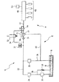
図1では、燃料システムが全体的に符号10を有している。この燃料システム10は低圧領域12と高圧領域14とを有している。
In FIG. 1, the fuel system has a reference numeral 10 as a whole. The fuel system 10 has a
低圧領域12は蓄え容器16を有している。この蓄え容器16内には燃料18が蓄えられる。この燃料18は蓄え容器16から第1の燃料ポンプ20によって圧送される。この第1の燃料ポンプ20は電動式の燃料ポンプとして形成されている。この電動式の燃料ポンプ20は燃料を低圧燃料管路22に圧送する。この低圧燃料管路22には、流れ方向で見て電動式の燃料ポンプ20の後方にまずフィルタ24が設けられている。流れ方向で見てさらにフィルタ24の手前では低圧燃料管路22から、蓄え容器16に戻る分岐管路26が分岐している。この分岐管路26には圧力制限弁28が配置されている。
The
低圧燃料管路22は第2の燃料ポンプ30に通じている。この第2の燃料ポンプ30は、ここには図示していない形式で内燃機関のカムシャフト(図示せず)によって駆動される。第2の燃料ポンプ30はシングルプランジャ型の高圧ポンプとして形成されている。この高圧ポンプ30の上流側では、低圧燃料管路22にさらに圧力減衰器32と逆止弁34とが配置されている。フィルタ24と圧力減衰器32との間では、低圧燃料管路22から分岐管路36が分岐している。この分岐管路36には低圧調整器38が配置されている。分岐管路36も同じく燃料18のための蓄え容器16に戻されている。高圧ポンプ30からは漏れ管路40が分岐管路36に通じている。
The low
出口側で高圧ポンプ30は燃料を高圧燃料管路42に圧送する。この高圧燃料管路42は逆止弁44を介して燃料集合管路46に通じている。さらに、この燃料集合管路46には燃料噴射弁48が接続されている。この燃料噴射弁48は燃料を内燃機関の燃焼室(図示せず)内に噴射する。燃料集合管路46内の圧力は圧力センサ50によって検出される。
で At the outlet side, the
高圧燃料管路42内の圧力および燃料集合管路46内の圧力、すなわち、燃料システム10の高圧領域14における圧力は量制御弁52を介して開ループ制御されかつ/または閉ループ制御される。この量制御弁52は、逆止弁44と高圧ポンプ30との間に設けられた高圧燃料管路42の領域を、逆止弁34と圧力減衰器32との間に設けられた低圧燃料管路22の領域に接続する。この接続は分岐管路54を介して行われる。量制御弁52は、図1には示していない開ループ制御・閉ループ制御ユニットによって制御される。さらに、この開ループ制御・閉ループ制御ユニットは圧力センサ50から信号を獲得する。こうして、燃料システム10の高圧領域14における圧力を制御するための閉じられた制御回路が形成される。
The pressure in the high-
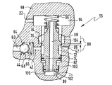
量制御弁52の故障時に燃料集合管路46内の、噴射弁48の機能性を損なう恐れがある過圧を回避するためには、高圧ポンプ30に圧力制限装置56が組み合わされている。この本発明による圧力制限装置56の第1実施例の正確な構造は図2から明らかである。
The
高圧ポンプ30と圧力制限装置56とは1つの共通のハウジング58内に収納されている。高圧ポンプ30のうち、図2には、圧送室60の領域と、この圧送室60の出口側に配置された出口弁44としか見ることができない。この出口弁44は球形の弁エレメント64を有している。この弁エレメント64はばね66によって弁座68に向かって負荷される。出口弁44の下流側には高圧燃料管路42を見ることができる。吸込み行程の間、図2に部分的にしか示していない圧送室60は高圧燃料管路42に対して出口弁44によってシールされている。
The high-
流れ方向で見て出口弁44のすぐ後方には孔70が設けられている。この孔70内にはピストン72が案内されている。このピストン72は第1のつば74と第2のつば76とを有している。ピストン72は第1のつば74と第2のつば76とを介して孔70内に案内されている。孔70と第1のつば74との嵌合は、孔70と第1のつば74との間の環状ギャップが絞りとして働くように設定されている。孔70と第2のつば76との嵌合は、孔70と第2のつば76との間に良好なシール作用が得られ、にもかかわらず、ピストン72がまだ孔70内で移動可能であるように設定されている。
A
第1のつば74と第2のつば76との間には、ピストン72が環状溝78を有している。この環状溝78は高圧燃料管路42に液圧的に接続されている。孔70の底部80とピストン72の第1のつば74とは補償室82を仕切っている。この補償室82は孔70と第1のつば74との間の環状ギャップを介して高圧燃料管路42に液圧的に接続されている。
The
ハウジング58内には、孔70に対して同心的に環状の切欠き84が設けられている。環状溝78とピストン72の第2のつば76とは制御縁部86を形成している。この制御縁部86は切欠き84と協働する。圧力制限装置56の、図2に示した閉鎖された状態では、制御縁部86が切欠き84に対して重なりを有している。この重なりは図2に符号88によって示してある。この結果、ピストン72のこの位置での高圧燃料管路42と切欠き84との間の液圧的な接続は遮断されている。
環状 An
第2のつば76は切欠き84よりも広幅に形成されているので、ピストン72は孔70内の位置とは無関係に常に第1のつば74と第2のつば76とによって孔70内に案内されている。
Since the
第2のつば76の上方では、ピストン72にシール円錐部90が一体成形されている。このシール円錐部90は、圧力制限装置56の、図2に示した閉鎖位置において、ハウジング58内に形成されたシール座92と一緒に切欠き84をばね室94から分離している。さらに、このばね室94は低圧管路22に液圧的に接続されている。シール円錐部90とシール座92とは、内燃機関の停止時に高圧領域14における圧力を維持するために働く。ばね室94内には圧縮ばね96が配置されている。この圧縮ばね96は、一方の端部でハウジング58にかつ他方の端部でピストン72に支持されていて、このピストン72をそのシール円錐部90でシール座92に押し付けている。
シ ー ル Above the
圧力制限装置56が開放されている場合、つまり、第2のつば76の制御縁部86が環状溝78と切欠き84との間の液圧的な接続を解放している場合に切欠き84とばね室94との間の液圧的な接続も形成されるように、第2のつば76には、全周にわたって分配されて複数の切欠き98が加工されている。
本発明による圧力制限装置56の機能形式は以下の通りである。
The functional form of the
ポンプ30の圧送行程の間、圧送室60内の圧力が上昇しかつ逆止弁44が開放すると、高圧燃料管路42内の圧力も上昇し、燃料が高圧燃料管路42から補償室82内に流入し、この補償室82内の圧力が時間的にやや遅れて上昇する。補償室82内の圧力上昇の遅れは、第1のつば74と孔70との間の環状ギャップの絞り作用によって生ぜしめられる。補償室82内の圧力が、ばね96の圧着力を上回るのに十分な高さになるやいなや、ピストン72がシール座92から持ち上がる;すなわち、ピストン72が図2で見て上方に運動させられる。これによって、補償室82の容積も増加するので、高圧燃料管路42内の圧力上昇ひいては燃料システム10の高圧領域14(図1参照)全体における圧力上昇が減少させられる。重なり88と補償室82の容積とは、燃料システム10のノーマル運転中に燃料システム10の高圧領域14における圧力脈動が、燃料システム10の運転にもはや不利な影響を与えなくなるまで減少させられるように規定されている。さらに、重なり88と補償室82の容積とは、燃料システム10のノーマル運転中に高圧燃料管路42と低圧燃料管路22との間の液圧的な接続が解放されないように規定されている。これは、本発明による圧力制限装置56の使用によって、ノーマル運転中の燃料システム10の効率がほぼ不変に保たれることを意味している。
When the pressure in the
燃料システム10の圧送量調整装置が故障しており、これによって、燃料ポンプ30(図1参照)が常に十分な圧送量を圧送する場合には、高圧領域14における圧力ひいては高圧燃料管路42内の圧力も、ノーマル運転中の圧力脈動に比べて長い期間にわたって著しく上昇する。この結果、補償室82の容積が著しく増加させられ、制御縁部86が環状溝78と切欠き84との間の液圧的な接続を解放し、燃料が高圧燃料管路42からばね室94を介して低圧燃料管路22内に流入し、これによって、高圧燃料管路42内に形成された過圧の減少が生ぜしめられる。これによって、燃料システム10の高圧領域14が、圧送量調整装置の故障時に許容できないほど高い圧力に対して有効に防護される。
If the pumping control of the fuel system 10 is faulty and the fuel pump 30 (see FIG. 1) always pumps a sufficient pumping pressure, the pressure in the high-
図3には、圧力経過が時間tに関連して質的に示してある。高圧ポンプ30の出口側、すなわち、たとえば高圧燃料管路42および燃料集合管路46にコンスタントな容積が存在している場合には、燃料システム10の高圧領域14に高圧ポンプ30の圧力脈動に基づき約180barのピーク値に至るまでの圧力ピークが生ぜしめられる恐れがある。このような圧力ピークは図3に破線で示してある。この圧力ピークは、高圧ポンプ30による高圧燃料管路42内の燃料柱の加速に基づき生ぜしめられる。本発明による圧力制限装置56によって、燃料システム10のノーマル運転中に生ぜしめられる圧力ピークが前述した形式で回避される。この結果、高圧燃料管路42内の圧力上昇および燃料集合管路46内の圧力上昇がより少なくなる。このことは、図3に実線によって質的に示してある。燃料ポンプ30の圧送行程が終了するやいなや、逆止弁44が閉鎖し、ばね96がピストン72を補償室82の方向に押圧し、これによって、この補償室82の容積がその元々の値に減少する。補償室82から押し退けられた燃料は環状溝78を介して高圧燃料管路42内に流入し、したがって、燃料システム10の高圧領域14における圧力保持に貢献している。
FIG. 3 shows the pressure profile qualitatively in relation to time t. If a constant volume exists on the outlet side of the high-
制御縁部86と切欠き84との間の重なり88、ばね96の予荷重もしくはプレロードおよびばね定数ならびに補償室82の容積および第1のつば74と孔70との間の絞り作用は、すでに上述したように、燃料システム10の整然とした運転時の第2の燃料ポンプ30の圧送行程時に制御縁部86が切欠き84を解放せず、したがって、燃料が高圧領域14から低圧領域12に到達しないように互いに調和されていなければならない。燃料ポンプ30の量調整装置の故障または類似の影響を伴う別の故障が生ぜしめられた場合に初めて、補償室82の容積が著しく増加させられ、制御縁部86が切欠き84を解放し、過剰の燃料が切欠き84と、切欠き98と、ばね室94とを介して低圧燃料管路22内に流出することができる。これによって、燃料システム10の高圧領域14における許容できないほど高い圧力が有利に阻止される。
The
図4には、本発明による圧力制限装置56の別の実施例が示してある。同じ構成部材には同じ符号が付してあり、図2に関する全てのことが相応に当てはまる。
FIG. 4 shows another embodiment of the
図2に示した第1実施例に対する主要な違いは、ピストン72が第1のつば74の下方に第3のつば100を有していることにある。補償室82は、この実施例では、第1のつば74と第3のつば100との間に設けられていて、環状の室として形成されている。この環状の室の容積は、ピストン72がばね96の方向に運動させられる場合に増加させられる。
The main difference from the first embodiment shown in FIG. 2 is that the
孔70の底部80と第3のつば100とは室102を仕切っている。この室102は孔104を介してばね室94ひいては低圧燃料管路22に液圧的に接続されている。これによって、ピストン72の端面に作用する液圧的な力が補償される。
The bottom 80 of the
補償室82からピストン72にばね96の閉鎖力に抗して加えられる液圧的な力は、第1のつば74の直径D1と第3のつば100の直径D3との間の環状の差面にしか有効とならないので、この力は、圧力制限装置56の寸法が同じである場合には、補償室82内に位置する燃料によってピストン72の端面に加えられる、第1実施例(図2参照)による液圧的な力よりも小さくなっている。このことは、ばね96を可能な限り小さく形成することが目標とされている場合には有利であり、4mm未満の直径の場合には、本発明による圧力制限装置56を製作するための製造技術的な手間が極めて高くなる。したがって、図2に示した第1実施例の小型化には製造技術的なかつ経済的な限界が設けられている。
Hydraulic force applied against the closing force of the
図4に示した実施例によって、ばね96の閉鎖力に抗して作用する小さな液圧的な力を、製造技術的に問題のないピストン72の直径で製造技術的に比較的簡単に形成することができる。
With the embodiment shown in FIG. 4, a small hydraulic force acting against the closing force of the
この第2実施例の液圧的な特性は第1実施例の液圧的な特性にほぼ相当している。 The hydraulic characteristics of the second embodiment substantially correspond to the hydraulic characteristics of the first embodiment.
図5には、本発明による圧力制限装置56の第3実施例が示してある。第2実施例に対する主要な違いは、ピストン72がシール円錐部90を有していないことにある。圧力制限装置56の閉鎖位置では、ピストン72がその第3のつば100でハウジング58の段部106に載置していて、これによって、制御縁部86の最大の重なり88を規定している。
FIG. 5 shows a third embodiment of the
本発明による圧力制限装置56の第3実施例は、有利には、エンジンの停止後にまたはエンジンブレーキ運転中に高圧領域14における圧力が、規定された漏れを介して低下させられる燃料システム10に使用される。第2のつば76と孔70との間の嵌合ならびに重なり88の寸法設定によって、内燃機関のこの運転状態のために必要となる漏れを調整することができる。
The third embodiment of the
一般的に本発明による圧力制限装置56の設計時には、この圧力制限装置56の開放圧が、高圧燃料管路42を通る通流量と可能な限り無関係であることに注意が払われる。
It is generally noted when designing the
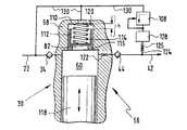
図6には、本発明による圧力制限装置56の第4実施例が示してある。この圧力制限装置56では、公知先行技術に基づき公知の慣用の圧力制限弁108が、高圧燃料管路42の圧力で負荷されるように配置されている。圧力制限弁108は座弁またはピストン弁として形成されていてよい。
FIG. 6 shows a fourth embodiment of the
圧力制限弁108が開放している場合には、この圧力制限弁108が、高圧燃料管路42と低圧燃料管路22との間の液圧的な接続を形成している。圧力制限弁108は、図6に示した第4実施例では、燃料ポンプ30内に組み込まれている。付加的な手段を備えていないと、圧力制限弁108は燃料ポンプ30の各圧送行程時に少なくとも短時間開放する恐れがある。なぜならば、各圧送行程によって、圧力制限弁108の開放圧よりも大きい圧力衝撃が高圧燃料管路42を通過するからである。
When the
以下に、燃料システム10のノーマル運転中の圧力制限弁108の望ましくない開放を阻止する手段を説明する。
In the following, means for preventing undesired opening of the
図6に示した実施例では、燃料ポンプ30のハウジング58内に補償孔110が設けられている。この補償孔110内には補償ピストン112が密に案内されている。この補償ピストン112は、一方の端部でハウジング58にかつ他方の端部で補償ピストン112に支持されている圧縮ばね114によって、補償孔110の、第1のストローク制限手段として働く段部116に向かって押圧される。補償ピストン112は補償室82を仕切っている。この補償室82は燃料ポンプ30の圧送室60に直接続いている。図6には、この圧送室60が完全に示してある。この図面には、ポンププランジャ118を認知することができる。このポンププランジャ118はハウジング58内に密に案内され、圧送室60を仕切っている。ポンププランジャ118の駆動装置は図示していない。
In the embodiment shown in FIG. 6, a
補償ピストン112の、図6に示した位置では、補償室82の容積が最小である。ポンププランジャ118の圧送行程の間、補償ピストン112に作用する圧送室60内の圧力が燃料ポンプ30の圧縮ばね114のプレロードを上回ると、補償ピストン112が段部116から持ち上り、圧送室60から遠ざけられる。これによって、補償室82の容積が増加するので、圧送室60内の圧力上昇ひいては高圧燃料管路42内の圧力上昇も制限される。補償ピストン112の最大の行程は図6に「h」で示してある。この最大の行程hは、補償ピストン112が補償孔110の頂部120に接触した場合に達成される。ポンププランジャ118がその上死点に到達し、その後、再び下死点の方向に運動させられると、圧送室60内の圧力が迅速に低下するので、圧縮ばね114が補償ピストン112を再び段部116に当て付けることができる。これによって、燃料が補償室82から圧送室60内に戻される。
At the position of the
圧縮ばね114のプレロードと補償ピストン112の直径とは、この補償ピストン112が、一方では、燃料システム10の高圧領域14における通常の運転圧を上回る圧力で初めて開放するように設定される。他方では、補償ピストン112はすでに圧力制限弁108の開放圧への到達前に段部116から持ち上がる。これによって、燃料ポンプ30の良好な効率が保証されており、同時に、短時間の圧力ピークが圧力制限弁108の開放を生ぜしめ得ることが有利に阻止される。
プ レ The preload of the
圧送室60と逆止弁44との間には第1の絞り122が設けられている。この第1の絞り122は、圧送室60内の圧力勾配が高い場合に高圧燃料管路42内の圧力ピークの減衰に貢献するように設計されている。しかし、第1の絞り122の設計時には、この第1の絞り122での圧力損失が過度に大きくならないように注意しなければならない。なぜならば、燃料ポンプ30の圧送量が全て第1の絞り122を通流するからである。
第 A
付加的には、高圧燃料管路42を圧力制限弁108に接続する分岐管路124に第2の絞126りと付加容積128とが配置されている。この第2の絞り126と付加容積128とは低域通過フィルタとして作用し、したがって、燃料ポンプ30の圧送行程によって生ぜしめられた圧力脈動に基づく圧力制限弁108の望ましくない短時間の開放を付加的に阻止している。
Additionally, a
圧力制限弁108と補償ピストン122の裏側とは漏れ管路130を介して低圧燃料管路22に接続されている。
The
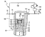
図7には、本発明による圧力制限装置56の別の実施例が示してある。図6に示した第4実施例に対する主要な違いは、補償ピストン112と補償孔110とが燃料ポンプ30のポンププランジャ118内に配置されていることにある。補償ピストン112は、図6および図7に示した実施例では、液圧的に同様に作用する。補償ピストン112の裏側からの漏れ導出は、長手方向孔132と、横方向孔134と、漏れ管路130に接続された環状溝136とを介して行われる。
FIG. 7 shows another embodiment of the
補償ピストン118はリテーナリング140によって位置決めされる。このリテーナリング140は同時にストローク制限手段としても働く。リテーナリング140は、補償孔110に設けられた溝142内に嵌め込まれる。
The
10 燃料システム、 12 低圧領域、 14 高圧領域、 16 蓄え容器、 18 燃料、 20 第1の燃料ポンプ、 22 低圧燃料管路、 24 フィルタ、 26 分岐管路、 28 圧力制限弁、 30 第2の燃料ポンプ、 32 圧力減衰器、 34 逆止弁、 36 分岐管路、 38 低圧調整器、 40 漏れ管路、 42 高圧燃料管路、 44 逆止弁、 46 燃料集合管路、 48 燃料噴射弁、 50 圧力センサ、 52 量制御弁、 54 分岐管路、 56 圧力制限装置、 58 ハウジング、 60 圧送室、 64 弁エレメント、 66 ばね、 68 弁座、 70 孔、 72 ピストン、 74 第1のつば、 76 第2のつば、 78 環状溝、 80 底部、 82 補償室、 84 切欠き、 86 制御縁部、 88 重なり、 90 シール円錐部、 92 シール座、 94 ばね室、 96 圧縮ばね、 98 切欠き、 100 第3のつば、 102 室、 104 孔、 106 段部、 108 圧力制限弁、 110 補償孔、 112 補償ピストン、 114 圧縮ばね、 116 段部、 118 ポンププランジャ、 120 頂部、 122 第1の絞り、 124 分岐管路、 126 第2の絞り、 128 付加容積、 130 漏れ管路、 132 長手方向孔、 134 横方向孔、 136 環状溝、 140 リテーナリング、 142 溝、 D1 直径、 D3 直径、 h 行程 Reference Signs List 10 fuel system, 12 low pressure region, 14 high pressure region, 16 storage container, 18 fuel, 20 first fuel pump, 22 low pressure fuel line, 24 filter, 26 branch line, 28 pressure limiting valve, 30 second fuel Pump, 32 pressure attenuator, 34 check valve, 36 branch line, 38 low pressure regulator, 40 leak line, 42 high pressure fuel line, 44 check valve, 46 fuel collecting line, 48 fuel injection valve, 50 Pressure sensor, 52 quantity control valve, 54 branch line, 56 pressure limiting device, 58 housing, 60 pumping chamber, 64 valve element, 66 spring, 68 valve seat, 70 hole, 72 piston, 74 first collar, 76th 2 collar, 78 annular groove, 80 bottom, 82 compensation chamber, 84 notch, 86 control edge, 88 overlap, 90 seal cone, 92 seal seat, 94 spring chamber, 6 compression spring, 98 notch, 100 third collar, 102 chamber, 104 hole, 106 step, 108 pressure limiting valve, 110 compensation hole, 112 compensation piston, 114 compression spring, 116 step, 118 pump plunger, 120 Top, 122 first restrictor, 124 branch line, 126 second restrictor, 128 additional volume, 130 leak line, 132 longitudinal hole, 134 lateral hole, 136 annular groove, 140 retaining ring, 142 groove, D 1 diameter, D 3 diameter, h stroke
Claims (17)
Applications Claiming Priority (1)
| Application Number | Priority Date | Filing Date | Title |
|---|---|---|---|
| DE2002145084 DE10245084A1 (en) | 2002-09-27 | 2002-09-27 | Pressure limiting device and fuel system with such a pressure limiting device |
Publications (1)
| Publication Number | Publication Date |
|---|---|
| JP2004116526A true JP2004116526A (en) | 2004-04-15 |
Family
ID=31969645
Family Applications (1)
| Application Number | Title | Priority Date | Filing Date |
|---|---|---|---|
| JP2003332145A Withdrawn JP2004116526A (en) | 2002-09-27 | 2003-09-24 | Pressure limiting device, and fuel system with pressure limiting device |
Country Status (3)
| Country | Link |
|---|---|
| EP (1) | EP1403509B1 (en) |
| JP (1) | JP2004116526A (en) |
| DE (2) | DE10245084A1 (en) |
Cited By (4)
| Publication number | Priority date | Publication date | Assignee | Title |
|---|---|---|---|---|
| JP2009222056A (en) * | 2008-03-13 | 2009-10-01 | Man Diesel Se | Engine fuel supply device |
| JP2012533010A (en) * | 2009-07-08 | 2012-12-20 | デルファイ・テクノロジーズ・ホールディング・エス.アー.エール.エル. | Pump device |
| JP2016205375A (en) * | 2015-04-20 | 2016-12-08 | 株式会社日立製作所 | Automotive fuel pump |
| KR20230032152A (en) * | 2021-08-30 | 2023-03-07 | 주식회사 현대케피코 | Pulsating Volume Extensible Type High Pressure Pump |
Families Citing this family (12)
| Publication number | Priority date | Publication date | Assignee | Title |
|---|---|---|---|---|
| DE102005062548A1 (en) * | 2005-12-27 | 2007-07-05 | Robert Bosch Gmbh | Common rail fuel system has fuel pump to pump fuel into rail, injectors through which fuel flows out of rail and connected valve device controlled by pressure in rail to avoid high frequency vibrations of fuel stored in rail |
| US20080022974A1 (en) * | 2006-07-28 | 2008-01-31 | Caterpillar Inc. | Multi-stage relief valve having different opening pressures |
| ITMI20072219A1 (en) * | 2007-11-23 | 2009-05-24 | Bosch Gmbh Robert | OVERPRESSURE VALVE AND HIGH PRESSURE PUMP INCLUDING THIS PRESSURE VALVE |
| DE102008020329A1 (en) * | 2008-04-23 | 2009-10-29 | Continental Automotive Gmbh | Device and method for fuel allocation and thus equipped internal combustion engine |
| US8240291B2 (en) | 2009-10-23 | 2012-08-14 | Caterpillar Inc. | Pressure relief valve |
| IT1400581B1 (en) * | 2010-06-18 | 2013-06-14 | Bosch Gmbh Robert | LUBRICATION AND OVERFLOW VALVE FOR A FUEL SUPPLY SYSTEM FROM A TANK TO AN INTERNAL COMBUSTION ENGINE AND SUCH A SYSTEM INCLUDING THAT VALVE. |
| DE102010064216A1 (en) * | 2010-12-27 | 2012-06-28 | Robert Bosch Gmbh | Pump, in particular a fuel injection system |
| DE102011003396A1 (en) * | 2011-01-31 | 2012-08-02 | Continental Automotive Gmbh | Pump unit for a high-pressure pump |
| DE102013212553A1 (en) * | 2013-06-28 | 2014-12-31 | Robert Bosch Gmbh | Hydraulic assembly for a fuel system of an internal combustion engine |
| DE102015205114B4 (en) | 2015-03-20 | 2022-08-04 | Volkswagen Aktiengesellschaft | Procedure for avoiding excessive system pressures in common rail systems |
| CN108386357B (en) * | 2018-04-18 | 2024-05-28 | 北京燕都碧城科技有限公司 | Liquid impact preventing device of single screw compressor |
| CN111608833B (en) * | 2020-05-07 | 2021-08-06 | 一汽解放汽车有限公司 | Safety pressure limiting valve for balancing pressure of common rail system |
Family Cites Families (5)
| Publication number | Priority date | Publication date | Assignee | Title |
|---|---|---|---|---|
| US5558068A (en) * | 1994-05-31 | 1996-09-24 | Zexel Corporation | Solenoid valve unit for fuel injection apparatus |
| JPH10299925A (en) * | 1997-04-23 | 1998-11-13 | Zexel Corp | Pressure control valve |
| JP3455419B2 (en) * | 1998-04-15 | 2003-10-14 | 三菱電機株式会社 | Diaphragm stopper structure of high pressure accumulator |
| DE10059425A1 (en) * | 2000-11-30 | 2002-06-06 | Bosch Gmbh Robert | Fuel injection pump for internal combustion engines, in particular diesel engines |
| DE10118936A1 (en) * | 2001-04-18 | 2002-11-07 | Bosch Gmbh Robert | Pressure limiting device and fuel system with such a pressure limiting device |
-
2002
- 2002-09-27 DE DE2002145084 patent/DE10245084A1/en not_active Withdrawn
-
2003
- 2003-02-20 EP EP20030003826 patent/EP1403509B1/en not_active Expired - Lifetime
- 2003-02-20 DE DE50304554T patent/DE50304554D1/en not_active Expired - Lifetime
- 2003-09-24 JP JP2003332145A patent/JP2004116526A/en not_active Withdrawn
Cited By (6)
| Publication number | Priority date | Publication date | Assignee | Title |
|---|---|---|---|---|
| JP2009222056A (en) * | 2008-03-13 | 2009-10-01 | Man Diesel Se | Engine fuel supply device |
| JP2012533010A (en) * | 2009-07-08 | 2012-12-20 | デルファイ・テクノロジーズ・ホールディング・エス.アー.エール.エル. | Pump device |
| JP2016205375A (en) * | 2015-04-20 | 2016-12-08 | 株式会社日立製作所 | Automotive fuel pump |
| US10443595B2 (en) | 2015-04-20 | 2019-10-15 | Hitachi, Ltd. | Automotive fuel pump |
| KR20230032152A (en) * | 2021-08-30 | 2023-03-07 | 주식회사 현대케피코 | Pulsating Volume Extensible Type High Pressure Pump |
| KR102540496B1 (en) | 2021-08-30 | 2023-06-07 | 주식회사 현대케피코 | Pulsating Volume Extensible Type High Pressure Pump |
Also Published As
| Publication number | Publication date |
|---|---|
| EP1403509A3 (en) | 2005-01-05 |
| DE50304554D1 (en) | 2006-09-21 |
| EP1403509B1 (en) | 2006-08-09 |
| EP1403509A2 (en) | 2004-03-31 |
| DE10245084A1 (en) | 2004-04-01 |
Similar Documents
| Publication | Publication Date | Title |
|---|---|---|
| EP1835169B1 (en) | High-pressure fuel pump | |
| JP4415929B2 (en) | High pressure fuel supply pump | |
| JP5501272B2 (en) | High pressure fuel supply pump | |
| EP1898084B1 (en) | High-pressure fuel supply pump | |
| JP2004116526A (en) | Pressure limiting device, and fuel system with pressure limiting device | |
| JP2004138062A (en) | Pressure limiting valve and fuel system equipped therewith | |
| JP4940329B2 (en) | High pressure fuel supply pump | |
| KR101857376B1 (en) | Pump arrangement and system for a motor vehicle | |
| JP5589121B2 (en) | High pressure fuel supply pump | |
| JP2002332931A (en) | Pressure limiting device and fuel system provided with this pressure limiting device | |
| JP6649483B2 (en) | High pressure fuel supply pump | |
| JP6697552B2 (en) | High pressure fuel supply pump | |
| KR20140147101A (en) | Flow restrictor with ball and throttle | |
| JP6483196B2 (en) | High pressure fuel supply pump | |
| KR20100026968A (en) | Fuel supply system of internal combustion engine | |
| JP2003269294A (en) | Hydraulic pressure reducing device for fuel injection valve | |
| US6648610B2 (en) | Fuel injection system with structurally biased relief valve | |
| JP6681487B2 (en) | High pressure fuel supply pump | |
| WO2016103945A1 (en) | Valve mechanism and high-pressure fuel supply pump with same | |
| JP2002303226A (en) | High pressure fuel pump | |
| JP6165674B2 (en) | High pressure fuel supply pump | |
| JP2019132275A (en) | High-pressure connection device for high-pressure fuel pump of fuel injection system, and high-pressure fuel pump | |
| JP7089399B2 (en) | Manufacturing method of fuel supply pump and fuel supply pump | |
| EP1247976A2 (en) | Over-pressure relief valve in a fuel system | |
| JP6596542B2 (en) | Valve mechanism and high-pressure fuel supply pump provided with the same |
Legal Events
| Date | Code | Title | Description |
|---|---|---|---|
| A621 | Written request for application examination |
Free format text: JAPANESE INTERMEDIATE CODE: A621 Effective date: 20060922 |
|
| A761 | Written withdrawal of application |
Free format text: JAPANESE INTERMEDIATE CODE: A761 Effective date: 20061006 |