JP2004111765A - Narrow-band laser device - Google Patents
Narrow-band laser device Download PDFInfo
- Publication number
- JP2004111765A JP2004111765A JP2002274356A JP2002274356A JP2004111765A JP 2004111765 A JP2004111765 A JP 2004111765A JP 2002274356 A JP2002274356 A JP 2002274356A JP 2002274356 A JP2002274356 A JP 2002274356A JP 2004111765 A JP2004111765 A JP 2004111765A
- Authority
- JP
- Japan
- Prior art keywords
- band
- narrow
- heat
- laser device
- narrowing
- Prior art date
- Legal status (The legal status is an assumption and is not a legal conclusion. Google has not performed a legal analysis and makes no representation as to the accuracy of the status listed.)
- Granted
Links
Images


Landscapes
- Lasers (AREA)
Abstract
Description
【0001】
【発明の属する技術分野】
本発明は、波長を狭帯域化した狭帯域化レーザ装置に関する。
【0002】
【従来の技術】
従来から、波長を狭帯域化したエキシマレーザ装置などの狭帯域化レーザ装置において、狭帯域化光学素子及びその周囲の気体の温度変化を小さくして、波面の乱れを抑制する技術が知られている。(例えば、特許文献1参照。)図15は、同公報に開示された従来技術に係るエキシマレーザ装置を表しており、以下図15に基づいて従来技術を説明する。
【0003】
図15において、エキシマレーザ装置11は、フッ素を含むレーザガスを封入したレーザチャンバ12を備えている。レーザチャンバ12の前後部には、レーザ光21を透過するウィンドウ17,19がそれぞれ付設されている。
レーザチャンバ12の内部には、主電極14,15が紙面と垂直に対向して配置され、主電極14,15間で放電を起こすことにより、レーザガスを励起してレーザ光21を発生させる。
【0004】
発生したレーザ光21は、レーザチャンバ12の後方(図15中右方)に付設された狭帯域化ボックス31の内部に入射する。
狭帯域化ボックス31の内部には、例えば2個のプリズム32,32と、グレーティング33とが配設されている。
レーザ光21は、プリズム32,32でビーム幅を広げられ、グレーティング33の回折面33Aで回折され、所定の中心波長とその近傍の波長のみを折り返される。これにより、レーザ光21が狭帯域化される。
【0005】
狭帯域化されたレーザ光21は、フロントミラー16とグレーティング33との間で反射を繰り返す間に、主電極14,15間で増幅される。そして、その一部がフロントミラー16を部分透過して、前方に出射する。
前方にはビームスプリッタ22が配置され、レーザ光21の一部をサンプリングして、波長測定装置35によりその中心波長及びスペクトル線幅をモニタリングしている。
【0006】
グレーティング33及びプリズム32,32のうち少なくとも1つは、回転自在の回転ステージ(図示せず)上に搭載されている。レーザコントローラ29は、波長測定装置35の検出結果に基づき、回転ステージに指令を出力して、レーザ光21の中心波長及びスペクトル線幅が、目標値となるように制御を行なう。これを、波長制御と言う。
尚、グレーティング33やプリズム32,32等の間に、図示しないミラーを介在させ、このミラーを回転ステージによって回転させて波長制御を行なう場合もある。
【0007】
このとき、レーザ光21が狭帯域化ボックス31の内部の、プリズム32,32やグレーティング33等の光学素子の表面で乱反射したり、光学素子に吸収されたりすることにより、光学素子、特にグレーティング33近傍の温度が次第に上昇する。その結果、グレーティング33の回折面33A近傍の空気の屈折率に不均一が生じて、レーザ光21の波面が乱れ、スペクトル特性やビームプロファイルの不安定化を引き起こす。
【0008】
尚、このときのスペクトル特性とは、例えば中心波長や、スペクトル線幅や、或いはスペクトル純度等を指している。スペクトル純度とは、波長の強度分布の形状を示す指標の1つであり、レーザ光21の全エネルギーの、例えば95%が収まる波長幅を示している。
【0009】
このような波面の乱れを防止するために、狭帯域化ボックス31の内部には、清浄で低反応性の、例えば窒素等のパージガスを噴き出す、パージガス噴出口54が設けられている。パージガス噴出口54から連続的に噴出されたパージガスは、グレーティング33の裏面33Bに吹きつけられ、レーザ光21によって熱せられたグレーティング33を冷却する。狭帯域化ボックス31の内部は、パージガスで満たされている。
これにより、レーザ光21による、グレーティング33の温度上昇及び回折面33A近傍の気体の揺らぎによる波面の不安定化を防ぎ、ビームプロファイルやスペクトル特性の向上を図っている。
【0010】
また、パージガスを、グレーティング33の回折面33Aに平行にエアカーテン状に流すようにしている。これにより、グレーティング33の回折面33Aにおける熱を除去し、波面の不安定化を防いでいる(例えば、特許文献2参照。)。
【0011】
【特許文献1】
特許第2696285号公報(第1図)
【特許文献2】
特開2001−135883号公報(第6図A〜C)
【0012】
【発明が解決しようとする課題】
しかしながら、前記従来技術には、次に述べるような問題がある。
即ち、これらの従来技術は、レーザ光21の照射に起因する、グレーティング33近傍の気体の温度上昇を防ごうというものであり、その手段として外部からパージガスを導入して、これをグレーティング33に吹きつけている。
【0013】
図16に、従来技術における、レーザ光21のスペクトル波形の半値全幅(FWMH)の変化を、グラフで示す。図16において、横軸がエキシマレーザ装置11の発振を開始した時刻t0からの経過時間t、そして縦軸が、スペクトル波形の半値全幅の変化を示している。
また、グラフの下部に示した3つの波形は、それぞれ時刻t0、t1、t2におけるスペクトル波形を示している。横軸が波長λであり、縦軸がその波長に対する光強度である。
図16に示すように、スペクトル波形の半値全幅は、時刻t0から時刻t1にかけて、次第に大きくなる。そして、時刻t1から時刻t2の間に次第に小さくなり、ほぼ元に戻る。
【0014】
従来技術においては、上記のような方法でグレーティング33の温度上昇、及び回折面33A近傍の気体の揺らぎによるスペクトル形状の不安定化を回避しようとしている。これにも拘らず、実際には図16に示すように、スペクトル波形の半値全幅の不安定、即ちスペクトル形状の不安定が発生している。特に、エキシマレーザ装置11を立ち上げた直後において、その傾向は著しい。
尚、図16に示すグラフにおいては、半値全幅のみを示しているが、スペクトル純度などの、他のスペクトル特性も低下することがわかっている。
【0015】
本発明は、上記の問題に着目してなされたものであり、スペクトル特性が安定した、狭帯域化レーザ装置を提供することを目的としている。
【0016】
【課題を解決するための手段、作用及び効果】
本発明者は鋭意研究した結果、上記のようなスペクトル形状の不安定の発生は、狭帯域化ボックス31の外部近傍に配置されるレーザチャンバ12等の発熱源からの熱を、狭帯域化ボックス31が受けることによって発生することを見出した。
【0017】
図3に、エキシマレーザ装置11の平面図を示す。図3において、レーザチャンバ12の周囲には断熱材38が貼着されている。
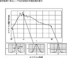
このように、発熱源からの熱が狭帯域化ボックス31に伝わりにくいようにした場合の、レーザ光21のスペクトル波形の半値全幅の変化を調べた結果を、グラフで図14に示す。図14において、横軸がエキシマレーザ装置11の発振を開始した時刻t0からの経過時間t、そして縦軸が、スペクトル波形の半値全幅の変化を示している。
【0018】
図14に示すように、時刻がt0から時刻t2まで経過しても、スペクトル波形の半値全幅は殆んど変化しなかった。これは、断熱材38を用いなかった従来技術における、図16と比較すると、より明らかである。図14に示すグラフにおいては、半値全幅のみを示しているが、スペクトル純度などの、他のスペクトル特性も良好であることがわかっている。
即ち、プリズム32,32やグレーティング33等の狭帯域化光学部品が収容された狭帯域化ボックス31の外部にある発熱源からの熱が、狭帯域化ボックス31に伝わらないようにすると、スペクトル波形の安定性が向上する。
【0019】
図16に示したようなスペクトル特性の変化が起きる原因についてのメカニズムは、詳細には分っていないが、次のように推測される。
即ち、発熱源からの熱が狭帯域化ボックス31に伝わり、狭帯域化ボックス31が加熱される場合、狭帯域化ボックス31は必ずしも均一に加熱されるわけではなく、不均一に加熱される可能性が高いと考えられる。
【0020】
図17に、狭帯域化ボックス31の内部を平面視で示した、温度分布のモデル図を示す。図17に示すように、狭帯域化ボックス31の内部には、発熱源からの加熱により、高温領域74が局所的に存在するものと考えられる。
この高温領域74が、グレーティング33や光路の近傍に存在すると、高温領域74近傍の気体と、高温領域74近傍ではない領域の気体との間には温度差が生じる。尚、狭帯域化ボックス31内部の気体とは、空気、もしくは、狭帯域化ボックス31内部がパージされている場合にはパージガスが相当する。
その結果として、気体の密度分布が、場所によって不均一となる。さらには、温度差による、部分的な気体の対流も発生し、これがさらに気体の密度分布を不均一にすると考えられる。
【0021】
図18に、図17に示すモデル図の、光路中のA,B,Cの各地点における温度の、時間経過をグラフで示す。縦軸が温度、横軸が時間tである。図17に示すように、各地点A,B,Cは、それぞれ高温領域74からの距離が異なる。従って、図18に示すように、それぞれの地点の温度上昇の度合いが異なってくる(高温領域74に近い地点Cが速く、遠い地点Aが遅い)。
その結果、各地点A,B,C間において気体の密度の差が発生し、また各地点A,B,C間の温度差により発生した対流により、気体の揺らぎも発生するものと考えられる。よって、レーザ光21の光路における気体密度の不均一さが発生し、光路を通るレーザ光21の波面が不安定となって、ビームプロファイルやスペクトル特性等が不安定になると考えられる。
このような屈折率の不均一は、ビーム幅が広がったグレーティング33近傍において、波面の乱れに、より大きな影響を及ぼすことになる。
【0022】
また、グレーティング33やプリズム32,32等の狭帯域化光学素子が、下方の発熱源から加熱されることにより、周囲よりも高温となって気体を局所的に加熱し、屈折率の不均一をもたらす場合もある。
さらには気体ばかりでなく、プリズム32,32等の、レーザ光21が透過する光学素子が加熱され、その内部において、屈折率の不均一をもたらす場合もあると考えられる。
【0023】
図19は、レーザ光21のスペクトル波形の半値全幅の変化を、図18の時間軸tに対応させたグラフであり、図16に示したスペクトル波形の変化のモデル図である。図19において、横軸はエキシマレーザ装置11の発振を開始した時刻t0からの経過時間t、縦軸はスペクトル波形の半値全幅を示している。
図19に示すように、スペクトル波形の半値全幅は、時刻t0から時刻t1にかけて、次第に大きくなる。そして、時刻t1から時刻t2の間に次第に小さくなり、ほぼ元に戻る。
【0024】
時刻t0から時刻t1において、スペクトル波形の半値全幅が大きくなる理由は、以下の通りであると考えられる。
狭帯域化ボックス31外部の発熱源からの熱によって生じる狭帯域化ボックス31内の温度上昇特性は、例えば図17の各地点A,B,Cにおいて異なる。特に、エキシマレーザ装置11の発振を開始した時刻t0からは、発熱源の温度上昇が開始されるため、時刻t1までの間における、各地点A,B,Cでの温度上昇特性の違いが特に大きく、その結果各地点A,B,C間の温度差が大きくなる。そのため各地点A,B,C間の気体の密度分布も不均一となり、また温度差に起因する対流による気体のゆらぎも大きいと考えられる。
従って、時刻t0から時刻t1までは、光路を通るレーザ光21の波面も不安定となり、ビームプロファイルやスペクトル特性等の不安定さが大きくなるため、スペクトル波形の半値全幅が大きくなってしまう。
【0025】
その後、時刻t1を経過すると、点A,B,Cの温度上昇が緩和し始めて、やがてある温度に収束するように飽和し、地点A,B,C間の温度差が小さくなる。これは、狭帯域化ボックス31内部の、光路近傍の温度の不均一性が小さくなることを示している。
これにより、時刻t1以降は、光路を通るレーザ光21の波面の不安定さも徐々に小さくなる。その結果として、ビームプロファイルやスペクトル特性等が安定になり、スペクトル波形の半値全幅が所定の目標値に近づいていくと考えられる。
【0026】
一方、図20に、図3に示したようにレーザチャンバ12の周囲に断熱材38を貼着した場合の、各地点A,B,Cの温度変化を示す。横軸はエキシマレーザ装置11の発振を開始した時刻t0からの経過時間t、そして縦軸はスペクトル波形の半値全幅の変化を示している。
図20に示すように、発熱源からの熱を狭帯域化ボックス31に伝わりにくくすることにより、図17に示すモデル図における外部の発熱源に起因する高温領域74が、非常に小さくなる。その結果、各地点A,B,C間の温度差が、非常に小さくなり、ほぼ同様の温度変化を示すようになる。
【0027】
図21は、レーザ光21のスペクトル波形の半値全幅の変化を、図20の時間軸tに対応させたグラフであり、図14のモデル図である。図21に示すように、時刻がt0から時刻t2まで経過しても、スペクトル波形の半値全幅はほとんど変化しない。
即ち、図20に示したように各地点A,B,Cでの温度上昇の度合いがほぼ同様となっているため、各地点A,B,C間における気体の密度の差が小さくなる。また、各地点A,B,Cの温度差も小さいので、各地点A,B,C間に起きる対流も小さく、従って、気体の揺らぎも殆んど発生しないものと考えられる。その結果、光路を通るレーザ光21の波面の不安定さが小さくなり、ビームプロファイルやスペクトル特性等が安定化するため、スペクトル波形の半値全幅が所定の目標値に近くなっていると考えられる。
【0028】
従来は、光路を通過するレーザ光21による加熱の影響のみを考慮し、外部の発熱源から伝わる熱による狭帯域化ボックス31への加熱の影響を考慮していなかった。そのため、従来技術のようにグレーティング33へパージガスを吹きつけても、スペクトル特性の変動が発生していた。
以上のように本発明は、外部の発熱源からの熱が、狭帯域化光学素子やレーザ光21の光路に伝わらないようにすることによって、スペクトル特性が安定した狭帯域化レーザ装置を提供する。
【0029】
即ち、上記の目的を達成するために本発明は、
レーザ光の波長を狭帯域化する狭帯域化光学素子を備えた狭帯域化レーザ装置において、
前記狭帯域化光学素子及びレーザ光の光路の少なくともいずれか一方に発熱源から熱が伝わるのを防止する熱伝達防止手段を備えている。
これにより、狭帯域化光学素子近傍のレーザ光の光路において、発熱源から伝わった熱による不均一な加熱によって生じる、屈折率の不均一が生じることが少なく、波面の乱れが小さくなる。
【0030】
また本発明は、狭帯域化光学素子を囲繞する狭帯域化ボックスを備えている。
狭帯域化光学素子が狭帯域化ボックスの内部にある場合には、上記の不均一な加熱によって生じる、屈折率の不均一が起こりやすい。従って、本発明の効果が高い。
【0031】
また本発明は、前記熱伝達防止手段が、前記狭帯域化光学素子と発熱源との間に設置された、熱を遮断する断熱手段である。
これにより、狭帯域化光学素子やその近傍の光路が温められにくくなり、発熱源から伝わった熱による不均一な加熱によって生じる、屈折率の不均一が起こりにくい。
【0032】
また本発明は、前記断熱手段が、狭帯域化ボックスの近傍に設置されている。これにより、どのような場所に発熱源があっても、熱が狭帯域化ボックスに伝わるのを、確実に防止することができる。
【0033】
また本発明は、前記断熱手段が、発熱源の近傍に設置されている。
これにより、例えば狭帯域化光学素子が複数の箇所にあるような場合にも、断熱手段を増やす必要がない。
【0034】
また本発明は、前記断熱手段が断熱材である。
断熱材は安価で取り扱いが容易であり、断熱効果も大きい。
【0035】
また本発明は、前記断熱手段が、内部に冷媒を流す配管である。
これにより、断熱効果が大きく、より確実に狭帯域化光学素子に熱が伝わるのを防止できる。
【0036】
また本発明は、前記冷媒が、温度を略一定に温調されている。
これにより、断熱効果が大きく、より確実に狭帯域化光学素子に熱が伝わるのを防止できる。
【0037】
また本発明は、前記断熱手段が、内部が真空の真空容器である。
これにより、断熱効果が大きく、より確実に狭帯域化光学素子に熱が伝わるのを防止できる。
【0038】
また本発明は、前記断熱手段が、内部に温度が略一定の恒温気体が流れる中空容器である。
これにより、断熱効果が大きく、より確実に狭帯域化光学素子に熱が伝わるのを防止できる。
【0039】
また本発明は、前記熱伝達防止手段が、発熱源の周囲を通った空気の流れが狭帯域化光学素子又は狭帯域化ボックスに到達するのを妨げている。
これにより、発熱源によって温められた空気が、狭帯域化光学素子に達することが少なく、狭帯域化光学素子が加熱されにくくなる。
【0040】
また本発明は、前記熱伝達防止手段が、発熱源の周囲を通った空気の流れが狭帯域化光学素子又は狭帯域化ボックスに到達するのを妨げるように配置された断熱材である。
断熱材は安価で取り扱いが容易であり、断熱効果も大きい。
【0041】
また本発明は、前記熱伝達防止手段が、空気の流れが狭帯域化光学素子又は狭帯域化ボックスの周囲を通った後で、発熱源の周囲を通るようにしている。
これにより、空気の流れによって熱が運ばれることが少なくなり、狭帯域化光学素子が熱せられにくくなる。
【0042】
また本発明は、前記熱伝達防止手段が、レーザチャンバ内部の送風機を駆動する駆動手段、及びレーザチャンバ内部の熱交換器に冷媒を流す冷却配管のうち少なくとも1つを、狭帯域化光学素子に対し、レーザ媒質を封入したレーザチャンバを挟んで反対側に配置している。
これにより、発熱源である冷却配管や駆動手段から狭帯域化光学素子までの距離が遠くなり、熱が伝わりにくくなる。
【0043】
また本発明は、前記発熱源が、レーザ媒質を封入したレーザチャンバ、レーザチャンバ内部の送風機を駆動する駆動手段、及びレーザチャンバ内部の熱交換器に冷媒を流す冷却配管のうち少なくとも1つである。
これらの発熱源は、発熱量が特に大きく、狭帯域化光学素子への熱伝達を防止することにより、波面の乱れを小さくする効果が大きい。
【0044】
【発明の実施の形態】
以下、図を参照しながら、本発明に係る実施形態を詳細に説明する。
まず、第1実施形態を説明する。図1は、第1実施形態に係る狭帯域化レーザ装置の一例として示された、狭帯域化エキシマレーザ装置11(以下、エキシマレーザ装置11と言う)の平面図、図2はその正面図である。図1〜図2において、エキシマレーザ装置11は、フッ素を含むレーザガスを封入したレーザチャンバ12を備えている。
【0045】
レーザチャンバ12の前部(図1中右側)及び後部には、レーザ光21を透過するウィンドウ17,19が、レーザチャンバ12の長手方向に対してブリュースタ角をなして、それぞれ付設されている。
【0046】
レーザチャンバ12の前後方には、キャビティプレート40,40が互いに略平行にそれぞれ設置されている。キャビティプレート40,40間は、レーザチャンバ12の長手方向に沿った、3本のインバーロッド41によって、連結されている。キャビティプレート40,40とレーザチャンバ12との間は、それぞれベローズ55,55によって接続されている。キャビティプレート40,40には、レーザ光21が通過する図示しない通過孔が設けられている。
【0047】
レーザチャンバ12の内部には、主電極14,15が対向して配置され、主電極14,15間で主放電を起こすことにより、レーザガスを励起してレーザ光21を発生させる。
発生したレーザ光21は、レーザチャンバ12の後側のキャビティプレート40に固定された狭帯域化ボックス31の内部に入射する。
【0048】
狭帯域化ボックス31の内部には、例えば2個のプリズム32,32と、グレーティング33とが配設されている。グレーティング33は、前記波長制御を行なうための、回転ステージ56上に搭載されている。65は、プリズム32を支持するホルダである。
レーザ光21は、プリズム32,32でビーム幅を広げられ、グレーティング33の回折面33Aで回折され、所定の中心波長とその近傍の波長のみを折り返される。これにより、レーザ光21の波長が狭帯域化される。
【0049】
図1に示すように、狭帯域化ボックス31には、その内部に低反応性で清浄なパージガスを導入するパージガス導入口57と、パージガスを排出するパージガス排出口58とが設けられている。矢印59に示すように、パージガス導入口57からは、連続的にパージガスが導入され、狭帯域化ボックス31の内部は、常にパージガスで満たされている。
パージガスとしては、例えば窒素が好適であるが、その他には不活性ガスでもよい。
【0050】
狭帯域化されたレーザ光21は、フロントミラー16とグレーティング33との間で反射を繰り返す間に、主電極14,15間で増幅される。そして、その一部がフロントミラー16を部分透過して、前方に出射する。
【0051】
図2に示すように、レーザチャンバ12の内部には、貫流ファン24等の送風機と、熱交換器13とが配設されている。貫流ファン24は、新鮮なレーザガスを主電極14,15間に送り込み、主放電で熱せられたガスを熱交換器13へと循環して冷却する。
熱交換器13には、冷却配管39,39が接続されてレーザチャンバ12の外部に到達しており、内部に冷却水等の冷媒を流すことにより、レーザガスを冷却している。
【0052】
また、レーザチャンバ12の側壁には、貫流ファン24を駆動するモータ36が付設されている。モータ36の出力は、磁気カップリング37によって、レーザチャンバ12内部の貫流ファン24に伝達される。
【0053】
狭帯域化ボックス31の、少なくとも1つの外壁面には、例えばシート状の断熱材38が貼着されている。断熱材38は、モータ36や熱交換器13の冷却配管39等から発生する熱が狭帯域化ボックス31に伝わって、内部の温度が不均一に上昇するのを防止している。
断熱材38としては、発塵や有機物の発生が起きないものがよく、例えばテフロン(登録商標)が好適である。断熱材38の他の例としては、発泡剤やポリウレタン、或いはシリコンラバー等がある。
【0054】
尚、上記の実施形態においては、狭帯域化ボックス31の外壁に断熱材38を貼着するように説明したが、例えばレーザ光21に当たって不純物を出さないような断熱材38を用いるようにすれば、狭帯域化ボックス31の内壁に貼着してもよい。尚このとき、エキシマレーザ装置11のレーザ光21は、紫外線であるから反応性が高く、不純物を出さない断熱材38の材質の選定には、注意が必要である。尚、狭帯域化レーザ装置がフッ素分子レーザ装置である場合も、そのレーザ光はより波長の短い紫外線であるから、さらなる注意が必要である。
或いは、断熱性を有する材質、例えばセラミックス等を用いて狭帯域化ボックス31を構成してもよい。
【0055】
以上説明したように第1実施形態によれば、グレーティング33やプリズム32等の狭帯域化光学素子の周囲に断熱材38を配置している。これにより、狭帯域化光学素子やレーザ光21の光路が不均一に加熱されることが少なく、光路の気体の屈折率に、不均一が生じにくい。従って、レーザ光21の波面の乱れが小さく、ビームプロファイルやスペクトル特性が不安定になることが少ない。
【0056】
次に、第1実施形態に係る、他の構成例について、説明する。
図3に、エキシマレーザ装置11の平面図、図4に正面図を示す。図3、図4に示すように、レーザチャンバ12の周囲には、断熱材38が貼着されている。また、モータ36及び冷却配管39と狭帯域化ボックス31との間にも、断熱材38が図示しない手段によって固定されている。
【0057】
エキシマレーザ装置11において、レーザチャンバ12は最大の発熱源である。従って、レーザチャンバ12の表面から発せられた熱が、狭帯域化ボックス31に伝わり、その内部の温度を上げることがある。
これを防止するために、レーザチャンバ12の周囲に断熱材38を貼着し、熱が狭帯域化ボックス31に伝わるのを防いでいる。
【0058】
また、上記で説明したように、モータ36及び冷却配管39も、発熱源である。従って、これらから狭帯域化ボックス31に熱が伝わって、その内部を加熱するのを防止するために、モータ36及び冷却配管39と狭帯域化ボックス31との間に、断熱材38を固定している。
或いは、図示はしないがモータ36の周囲に断熱材38を巻いたり、冷却配管39の周囲に断熱材38を巻くようにしてもよい。
【0059】
即ち、エキシマレーザ装置11の発熱源と狭帯域化ボックス31との間に断熱材38を配置し、これらの発熱源から狭帯域化ボックス31に熱が伝わるのを防止している。これにより、発熱源から伝わる熱によって、狭帯域化ボックス31の内部が不均一に加熱されることが少ない。従って、狭帯域化光学素子31,32やレーザ光21の光路が不均一に加熱されることも少なく、光路における局所的な屈折率の不均一が起きにくくなるので、波面も乱れにくくなる。
【0060】
尚、上記の説明において、断熱材38はレーザチャンバ12に密着させて貼着するように説明したが、これに限られるものではなく、レーザチャンバ12の外壁から離して、他の固定手段によって固定してもよい。
またこのとき、図3に示したように、レーザチャンバ12から狭帯域化ボックス31に伝わる熱を遮断するために、キャビティプレート40に断熱材38を貼着するようにしてもよい。さらには、キャビティプレート40を断熱性の強いセラミック等で構成してもよい。
【0061】
また、他にも発熱源があるような場合には、断熱材38の位置は、上記説明に限定されるものではなく、適宜貼着するようにする。
さらに、すべての発熱源と狭帯域化ボックス31との間に、断熱材38を配置するように説明しているが、例えば特に影響の大きい発熱源と狭帯域化ボックス31との間に対してのみ、断熱対策を施すようにしてもよい。
【0062】
また、断熱材38の代わりに、銅やアルミニウム等の良熱伝導性の金属を、発熱源と狭帯域化ボックス31との間に配置してもよい。これにより、発熱源から発生した熱は上記金属において広がり、狭帯域化ボックス31をより均一に加熱する。即ち、上記金属は均熱板となって、狭帯域化ボックス31内部に局所的な高温領域74が発生するのを妨げる。
その結果、光路の気体の温度勾配が小さくなり、屈折率の不均一が緩和されて、波面の乱れが小さくなる。
【0063】
次に、第2実施形態について、説明する。
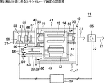
図5に、第2実施形態に係るエキシマレーザ装置11の平面図、図6に正面図を示す。図5、図6に示すように、狭帯域化ボックス31の上下の外壁には、恒温水配管42,42が接触している。恒温水配管42の内部には、略同一温度の恒温水(矢印60参照)が、常に流されている。
或いは、温水配管42が狭帯域化ボックス31の他の外壁に接触していてもよく、狭帯域化ボックス31の周囲を取り巻くようにしていてもよい。
【0064】
恒温水配管42の一部には、ヒータや冷却器等の温調手段68と、温度センサ69とが設けられており、上記温度センサ69からの信号に基づいて、温調コントローラ70が温調手段68の動作を制御することにより、恒温水配管42に流れる恒温水の温度を略一定に保っている。77は、恒温水を循環させるポンプである。
【0065】
これにより、発熱源であるレーザチャンバ12、モータ36、及び冷却配管39から発する熱が、狭帯域化ボックス31に到達するのを、恒温水が遮っている。
その結果、狭帯域化ボックス31内部に局所的な高温領域74が発生しにくくなり、光路の気体の温度勾配が小さくなる。即ち、屈折率の不均一が緩和されて、波面の乱れが小さくなる。
【0066】
尚、恒温水配管42を狭帯域化ボックス31に接触させるのではなく、中空の水ジャケットで狭帯域化ボックス31を囲い、その水ジャケットの内部に恒温水を流すようにしてもよい。或いは、狭帯域化ボックス31の壁を二重構造として、その内部に恒温水を流すようにしてもよい。
また、恒温水配管42が狭帯域化ボックス31の周囲全体を囲むのではなく、恒温水配管42を図4における断熱材38のように、狭帯域化ボックス31と発熱源との間に介在させるようにしてもよい。
【0067】
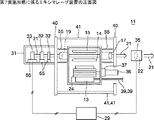
次に、第2実施形態に係るエキシマレーザ装置11の、他の構成例について説明する。図7はエキシマレーザ装置11の正面図である。図7に示すように、レーザチャンバ12、モータ36、及び冷却配管39の周囲には、中空の水ジャケット43が被せられており、その中には常に略同一温度の恒温水が流されている。
これにより、レーザチャンバ12、モータ36、及び冷却配管39等の発熱源から出た熱は、水ジャケット43の恒温水に吸収され、狭帯域化ボックス31には伝わらないようになっている。
【0068】
その結果、狭帯域化ボックス31内部に局所的な高温領域74が発生しにくくなり、光路の気体の温度勾配が小さくなる。即ち、屈折率の不均一が緩和されて、波面の乱れが小さくなる。
さらには、発熱源から発生した熱が恒温水によって奪われるので、狭帯域化ボックス31の内部の温度上昇自体が小さい。従って、光路における温度分布の不均一が小さくなって、波面の乱れはさらに小さくなる。
【0069】
尚、レーザチャンバ12、モータ36、及び冷却配管39の壁面を中空の二重構造にして、その内部に恒温水を流すようにしてもよい。
また、恒温水というように説明したが、必ずしも精密に温度制御をしなければならないわけではなく、温度が略一定か、或いは緩やかに変化するような水であればよい。例えば、水道水を用いることも可能である。また、恒温水は循環しても使い捨てでもよい。さらには、水ではなく、熱媒体でもよい。
【0070】
次に、第3実施形態について、説明する。
図8に、第3実施形態に係るエキシマレーザ装置11の正面図を示す。図8において、狭帯域化ボックス31の外側は、内部が真空または低圧で中空の、真空ジャケット44で囲まれている。
【0071】
これにより、真空ジャケット44が魔法瓶のように真空断熱機能を有し、外部から狭帯域化ボックス31内部への伝熱が非常に小さくなる。その結果、外部の発熱源から、狭帯域化ボックス31への熱の伝わり方が緩やかになり、狭帯域化ボックス31内部に局所的な高温領域74が発生しにくくなる。即ち、光路の気体の温度勾配が小さくなり、屈折率の不均一が緩和されて、波面の乱れが小さくなる。
【0072】
尚、真空ジャケット44は、狭帯域化ボックス31の周囲全部を囲むのではなく、発熱源との間に介在させるようにしてもよい。さらには、レーザチャンバ12、モータ36、及び冷却配管39等の発熱源を、真空ジャケット44で囲んでもよい。
また、狭帯域化ボックス31や発熱源の外側を真空ジャケット44で囲む代わりに、狭帯域化ボックス31や発熱源の壁を二重構造にして、その内部を真空にしてもよい。
【0073】
次に、第4実施形態について、説明する。
図9に、第4実施形態に係るエキシマレーザ装置11の正面図を示す。図9において、狭帯域化ボックス31の外側は、中空のエアジャケット45に囲まれている。尚、パージガス導入口57及びパージガス排出口58は、図示を省略する。
【0074】
エアジャケット45には、内部に温度が略一定の恒温気体(矢印62参照)を導入する気体導入口46と、恒温気体を排出する気体排出口47とが備えられている。
気体導入口46及び気体排出口47には、恒温気体を流す恒温気体配管78,78が接続されており、恒温気体配管78,78は、ヒータや冷却器等の温調手段71に接続されている。79は、恒温気体を循環させるためのブロアである。温調コントローラ73は、恒温気体配管78に付設された温度センサ72からの信号に基き、上記温調手段71の動作を制御することにより、恒温気体配管78,78に流れる気体を、恒温気体となるように温調する。
【0075】
エアジャケット45に恒温気体を連続的に流すことにより、発熱源から発生した熱は、狭帯域化ボックス31に伝わる前にこのエアジャケット45で遮断され、恒温気体とともに排出される。これにより、狭帯域化ボックス31の温度の不均一な上昇を防止し、波面の乱れを小さくすることができる。
さらには、発熱源から発生した熱が、恒温気体によって奪われるので、狭帯域化ボックス31の内部の温度が低くなり、波面の乱れはさらに小さくなる。
【0076】
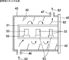
恒温気体としては、空気や窒素等が好適である。
このとき、恒温気体の流れに滞留部がなるべくできないように、狭帯域化ボックス31の周囲を一様に通過するように流れるようにするのがよい。例えば図10に示すように、恒温気体が狭帯域化ボックス31の周囲に螺旋状に流れるように、エアジャケット45の内部に適当な仕切り板48を設けるようにするとよい。
或いは、発熱源である、モータ36や冷却配管39と狭帯域化ボックス31との間に、エアカーテン状の恒温気体の流れを作るようにしてもよい。
【0077】
さらには、発熱源であるレーザチャンバ12、モータ36、及び冷却配管39等をエアジャケット45で囲んだり、発熱源と狭帯域化ボックス31との間にエアジャケット45を配置し、その内部に恒温気体を流すようにしてもよい。
【0078】
尚、上記実施形態においては、恒温気体の温度を略一定に温調するように説明したが、必ずしも温調制御をしなければならないものではなく、略一定か、或いは緩やかな温度変化をするような気体であってもよい。例えば、クリーンルームの空気を、そのまま用いてもよい。
【0079】
次に、第5実施形態について、説明する。
図11に、第5実施形態に係るエキシマレーザ装置11の正面図を示す。図11において、エキシマレーザ装置11は、レーザチャンバ12及び狭帯域化ボックス31を囲う、レーザカバー49を備えている。
尚、上記の第1〜第4実施形態においても、図示はしないが、レーザカバー49は設置されている。
【0080】
レーザカバー49の下部には、レーザカバー49内部の空気を排気して、エキシマレーザ装置11が設置されたクリーンルームの図示しない排気ダクトに排出する、排気ファン52と排気配管53とが付設されている。これは、例えばレーザカバー49内部に不純物や塵が溜まって、エキシマレーザ装置11に悪影響を与えるのを防止するためである。
またレーザカバー49の上部には、フィルタ50を挿入した開口部51が設けられ、空気はこの開口部51から、レーザカバー49の内部に入ってくる。
【0081】
このとき、開口部51からレーザカバー49の内部に入った空気は、矢印64に示すように、レーザチャンバ12の周辺を通って熱を帯びた後、排気ファン52へと導かれる。このような熱せられた空気が、狭帯域化ボックス31の近傍を通ると、狭帯域化ボックス31が熱せられてしまう。
これを防止するため、本実施形態においては、レーザチャンバ12と狭帯域化ボックス31との間に断熱材66を配置しており、熱い空気の流れを遮断している。
【0082】
このとき、断熱材66は上下方向においてレーザカバー49の上部にまで達しており、一例として、キャビティプレート40に固定される。また、図示はしないが、狭帯域化ボックス31の横方向においても、レーザカバー49にまで達している。
これにより、熱い空気の流れが狭帯域化ボックス31に届きにくくなるので、狭帯域化ボックス31内部に局所的な高温領域74が発生しにくくなり、光路の気体の温度勾配が小さくなる。即ち、屈折率の不均一が緩和されて、波面の乱れが小さくなる。
【0083】
次に、第6実施形態について、説明する。
図12に、第6実施形態に係るエキシマレーザ装置11の正面図を示す。図12において、エキシマレーザ装置11は、レーザチャンバ12及び狭帯域化ボックス31を囲うレーザカバー49を備えている。
レーザカバー49の狭帯域化ボックス31後方の上部には、フィルタ50を挿入した開口部51が付設されている。また、レーザカバー49の前方下部には、排気ファン52と排気配管53とが付設されている。
【0084】
矢印64に示すように、空気の流れは、開口部51からフィルタ50を通ってレーザカバー49の内部に入り、狭帯域化ボックス31の周囲を通り過ぎて、エキシマレーザ装置11の前部へと流れる。そして、レーザチャンバ12の周囲で熱せられた後、排気ファン52から排気配管53を通って排気される。
即ち、狭帯域化ボックス31の近傍の開口部51から空気を取り入れているため、狭帯域化ボックス31の周囲を通る空気は、発熱源によって熱せられていない。
これにより、狭帯域化ボックス31内部に局所的な高温領域74が発生しにくくなり、光路の気体の温度勾配が小さくなる。即ち、屈折率の不均一が緩和されて、波面の乱れが小さくなる。
【0085】
次に、第7実施形態について、説明する。
図13に、第7実施形態に係るエキシマレーザ装置11の正面図を示す。図13において、貫流ファン24を駆動するモータ36と、熱交換器13の冷却配管39,39とは、レーザチャンバ12に対して狭帯域化ボックス31と反対側の側面に設けられている。
【0086】
このようにすることにより、発熱源であるモータ36と冷却配管39とが狭帯域化ボックス31から遠ざかるので、狭帯域化ボックス31の受ける熱が小さくなる。
これにより、狭帯域化ボックス31内部に局所的な高温領域74が発生しにくくなり、光路の気体の温度勾配が小さくなる。即ち、屈折率の不均一が緩和されて、波面の乱れが小さくなる。
【0087】
尚、上記各実施形態のような、狭帯域化ボックス31と発熱源との間の熱の出入りを遮断する手段は、それぞれ単独で用いられると限られるものではなく、幾つかを併用されてもよい。
さらには、従来技術に示したような狭帯域化光学素子の冷却手段や、さらには狭帯域化ボックス31の内部を冷却するような冷却手段を併用すると、さらに効果的である。
【0088】
また、狭帯域化光学素子がレーザチャンバ12の後方にある場合についてのみ説明したが、前方や前方及び後方にあるような場合についても、同様に発熱源から発生した熱が狭帯域化光学素子に伝わらないようにすればよい。
さらには、狭帯域化光学素子が狭帯域化ボックス31の内部にある場合について説明したが、これに限られるものではない。狭帯域化ボックス31がなかったり、狭帯域化光学素子が狭帯域化ボックス31の外側にある場合についても、発熱源からの熱の伝熱を防ぐことにより、波面の乱れを防ぐことができる。
【0089】
また、上記の説明は、エキシマレーザ装置を例にとって行なったが、フッ素分子レーザ装置等、他の波長を狭帯域化するレーザ装置全般について、同様に応用が可能である。
また、狭帯域化光学素子として、グレーティング33について説明したが、例えばエタロン等でもよい。また、狭い意味での狭帯域化だけではなく、例えばフッ素分子レーザ装置等において、分散プリズムを用いて波長をシングルライン化するような場合にも、シングルライン化素子に対して用いることができる。
即ち、本願発明は、自由発振(フリーラン)状態に対して、レーザ光21のスペクトル特性を制限するようなレーザ装置全般について応用が可能であり、このようなスペクトル特性の制限を、狭帯域化と呼ぶ。
【0090】
また、波長制御を行なう場合について説明したが、狭帯域化光学素子を組み立て時に所定の目標波長で発振するように位置調整しておき、その後は波長制御を行なわないような狭帯域化レーザ装置についても、応用が可能である。
このような狭帯域化レーザ装置においては、狭帯域化ボックス31内部が加熱されると、狭帯域化光学素子を支持するホルダ65等が歪んで、スペクトル特性が所定の目標値から外れることがある。これに対し、本発明を応用することによってホルダ65等の歪みが少なくなり、波長制御を行なわなくても、常にスペクトル特性が目標値から許容範囲にあるようにすることも可能である。
【0091】
尚、上記断熱材等の断熱手段は、狭帯域化ボックス31内部や狭帯域化素子やレーザ光21の光路が、急激に加熱されて温度が上昇するのを防止する作用も備えている。これにより、狭帯域化ボックス31の内部における温度分布が、徐々に変化するので、波長制御を行なうことにより、スペクトル波形の半値全幅の大きな変化を防止する。
さらには、このような断熱手段は、狭帯域化ボックス31内部や狭帯域化素子やレーザ光21の光路の温度上昇自体も防止している。これにより、各地点A,B,Cの温度がそれほど上がらないため、温度分布による屈折率の不均一も起きにくく、波面の乱れが起きにくい。
【図面の簡単な説明】
【図1】第1実施形態に係るエキシマレーザ装置の平面図。
【図2】第1実施形態に係るエキシマレーザ装置の正面図。
【図3】第1実施形態に係るエキシマレーザ装置の平面図。
【図4】第1実施形態に係るエキシマレーザ装置の正面図。
【図5】第2実施形態に係るエキシマレーザ装置の平面図。
【図6】第2実施形態に係るエキシマレーザ装置の正面図。
【図7】第2実施形態に係るエキシマレーザ装置の正面図。
【図8】第3実施形態に係るエキシマレーザ装置の正面図。
【図9】第4実施形態に係るエキシマレーザ装置の正面図。
【図10】狭帯域化ボックス近傍の説明図。
【図11】第5実施形態に係るエキシマレーザ装置の正面図。
【図12】第6実施形態に係るエキシマレーザ装置の正面図。
【図13】第7実施形態に係るエキシマレーザ装置の正面図。
【図14】レーザ光の波長の半値全幅の変化を示すグラフ。
【図15】従来技術に係るエキシマレーザ装置の説明図。
【図16】従来技術に係るレーザ光の波長の半値全幅の変化を示すグラフ。
【図17】狭帯域化ボックスの内部を平面視で示した、温度分布のモデル図。
【図18】光路中の各地点における温度の時間経過を示すグラフ。
【図19】レーザ光のスペクトル波形の半値全幅の変化を示すグラフ。
【図20】光路中の各地点における温度の時間経過を示すグラフ。
【図21】レーザ光のスペクトル波形の半値全幅の変化を示すグラフ。
【符号の説明】
11:エキシマレーザ装置、12:レーザチャンバ、13:熱交換器、14:主電極(アノード)、15:主電極、16:フロントミラー、17:フロントウィンドウ、19:リアウィンドウ、20:レーザ光軸、21:レーザ光、22:ビームスプリッタ、24:貫流ファン、29:レーザコントローラ、31:狭帯域化ボックス、32:プリズム、33:グレーティング、35:波長測定装置、36:モータ、37:磁気カップリング、38:断熱材、39:冷却配管、40:キャビティプレート、41:インバーロッド、42:恒温水配管、43:水ジャケット、44:真空ジャケット、45:エアジャケット、46:気体導入口、47:気体排出口、48:仕切り板、49:レーザカバー、50:フィルタ、51:開口部、52:排気ファン、53:排気配管、54:パージガス噴出口、55:ベローズ、56:回転ステージ、57:パージガス導入口、58:パージガス排出口、59:パージガス流、60:恒温水、61:中空部、62:恒温気体、64:空気、65:ホルダ、66:断熱材、68:温調手段、69:温度センサ、70:温調コントローラ、71:温調手段、72:温度センサ、73:温調コントローラ、74:高温領域、77:ポンプ、78:恒温気体配管、79:ブロア。[0001]
TECHNICAL FIELD OF THE INVENTION
The present invention relates to a narrow-band laser device having a narrow wavelength.
[0002]
[Prior art]
Conventionally, in a narrow-band laser device such as an excimer laser device in which the wavelength is narrow, a technology is known in which the temperature change of the narrow-band optical element and the gas around it is reduced to suppress wavefront disturbance. I have. (See, for example,
[0003]
In FIG. 15, an
The
[0004]
The generated
Inside the band narrowing
The
[0005]
The
A
[0006]
At least one of the
In some cases, a mirror (not shown) is interposed between the
[0007]
At this time, the
[0008]
The spectral characteristics at this time refer to, for example, the center wavelength, the spectral line width, or the spectral purity. The spectral purity is one of the indices indicating the shape of the wavelength intensity distribution, and indicates a wavelength width in which, for example, 95% of the total energy of the
[0009]
In order to prevent such disturbance of the wavefront, a purge
This prevents the temperature rise of the
[0010]
Further, the purge gas is caused to flow in an air curtain shape in parallel with the
[0011]
[Patent Document 1]
Japanese Patent No. 2696285 (FIG. 1)
[Patent Document 2]
JP 2001-135883 A (FIGS. 6A to 6C)
[0012]
[Problems to be solved by the invention]
However, the conventional technique has the following problems.
That is, these conventional techniques are intended to prevent the temperature of the gas in the vicinity of the
[0013]
FIG. 16 is a graph showing a change in the full width at half maximum (FWMH) of the spectrum waveform of the
The three waveforms shown at the bottom of the graph show spectrum waveforms at times t0, t1, and t2, respectively. The horizontal axis is the wavelength λ, and the vertical axis is the light intensity for that wavelength.
As shown in FIG. 16, the full width at half maximum of the spectrum waveform gradually increases from time t0 to time t1. Then, the distance gradually becomes smaller between the time t1 and the time t2, and almost returns to the original state.
[0014]
In the prior art, the above method is used to avoid the temperature rise of the
Although only the full width at half maximum is shown in the graph shown in FIG. 16, it has been found that other spectral characteristics such as spectral purity also deteriorate.
[0015]
The present invention has been made in view of the above problem, and has as its object to provide a narrow-band laser device having a stable spectral characteristic.
[0016]
Means for Solving the Problems, Functions and Effects
As a result of the inventor's earnest research, the occurrence of the above-mentioned instability of the spectrum shape is caused by the heat from the heat source such as the
[0017]
FIG. 3 shows a plan view of the
FIG. 14 is a graph showing the result of examining the change in the full width at half maximum of the spectral waveform of the
[0018]
As shown in FIG. 14, even when the time elapses from t0 to t2, the full width at half maximum of the spectrum waveform hardly changed. This is more apparent when compared with FIG. 16 in the prior art in which the
That is, if the heat from the heat source outside the
[0019]
The mechanism of the cause of the change in the spectral characteristics as shown in FIG. 16 is not known in detail, but is presumed as follows.
That is, when the heat from the heat source is transmitted to the band-narrowing
[0020]
FIG. 17 shows a model diagram of the temperature distribution in which the inside of the
If the high-
As a result, the density distribution of the gas becomes non-uniform in some places. Furthermore, partial gas convection also occurs due to the temperature difference, which is considered to further make the gas density distribution non-uniform.
[0021]
FIG. 18 is a graph showing the lapse of time at the temperatures A, B, and C in the optical path in the model diagram shown in FIG. The vertical axis is temperature and the horizontal axis is time t. As shown in FIG. 17, each of the points A, B, and C has a different distance from the high-
As a result, it is considered that a difference in gas density occurs between the points A, B, and C, and that convection generated by a temperature difference between the points A, B, and C also causes gas fluctuation. Therefore, it is considered that the gas density in the optical path of the
Such non-uniformity of the refractive index has a greater effect on the wavefront disturbance in the vicinity of the grating 33 where the beam width is widened.
[0022]
In addition, when the band-narrowing optical elements such as the grating 33 and the
Further, it is considered that not only gas but also optical elements such as the
[0023]
FIG. 19 is a graph in which the change in the full width at half maximum of the spectrum waveform of the
As shown in FIG. 19, the full width at half maximum of the spectrum waveform gradually increases from time t0 to time t1. Then, the distance gradually becomes smaller between the time t1 and the time t2, and almost returns to the original state.
[0024]
The reason why the full width at half maximum of the spectrum waveform increases from time t0 to time t1 is considered as follows.
The temperature rise characteristics in the
Therefore, from time t0 to time t1, the wavefront of the
[0025]
Thereafter, when the time t1 has elapsed, the temperature rises at the points A, B, and C begin to ease, and the temperature eventually saturates so as to converge to a certain temperature, and the temperature difference between the points A, B, and C decreases. This indicates that the temperature non-uniformity near the optical path inside the
Thus, after time t1, the instability of the wavefront of the
[0026]
On the other hand, FIG. 20 shows temperature changes at points A, B, and C when the
As shown in FIG. 20, by making it difficult for the heat from the heat source to be transmitted to the band-narrowing
[0027]
FIG. 21 is a graph in which the change in the full width at half maximum of the spectral waveform of the
That is, as shown in FIG. 20, the degree of temperature rise at each of the points A, B, and C is substantially the same, so that the difference in gas density between the points A, B, and C becomes small. Further, since the temperature difference between the points A, B, and C is small, the convection between the points A, B, and C is small, and it is considered that the fluctuation of the gas hardly occurs. As a result, the instability of the wavefront of the
[0028]
Conventionally, only the effect of heating by the
As described above, the present invention provides a narrow-band laser device having stable spectral characteristics by preventing heat from an external heat source from being transmitted to the optical path of the narrow-band optical element or the
[0029]
That is, in order to achieve the above object, the present invention
In a narrow-band laser device having a narrow-band optical element for narrowing the wavelength of laser light,
At least one of the band-narrowing optical element and the optical path of the laser beam is provided with a heat transfer preventing unit for preventing heat from being transmitted from a heat source.
Accordingly, in the optical path of the laser light near the band-narrowing optical element, non-uniform refractive index caused by non-uniform heating due to heat transmitted from the heat source is less likely to occur, and wavefront disturbance is reduced.
[0030]
The invention also includes a band-narrowing box surrounding the band-narrowing optical element.
When the band-narrowing optical element is inside the band-narrowing box, the non-uniform refractive index caused by the non-uniform heating described above is likely to occur. Therefore, the effect of the present invention is high.
[0031]
Further, the present invention is a heat insulating means for blocking heat, wherein the heat transfer preventing means is provided between the band-narrowing optical element and a heat source.
This makes it difficult for the narrow-band optical element and the optical path in the vicinity thereof to be warmed, and for the refractive index to be non-uniform due to non-uniform heating due to heat transmitted from the heat source.
[0032]
Further, in the present invention, the heat insulating means is installed near a band narrowing box. Thereby, no matter where the heat source is located, it is possible to reliably prevent the heat from being transmitted to the band narrowing box.
[0033]
In the present invention, the heat insulating means is provided near a heat source.
Thus, for example, even when the band-narrowing optical element is present at a plurality of locations, it is not necessary to increase the number of heat insulating units.
[0034]
In the present invention, the heat insulating means is a heat insulating material.
The heat insulating material is inexpensive and easy to handle, and has a large heat insulating effect.
[0035]
Further, according to the present invention, the heat insulating means is a pipe through which a refrigerant flows.
Thereby, the heat insulation effect is large, and the heat can be more reliably prevented from being transmitted to the band-narrowing optical element.
[0036]
In the present invention, the temperature of the refrigerant is controlled to be substantially constant.
Thereby, the heat insulation effect is large, and the heat can be more reliably prevented from being transmitted to the band-narrowing optical element.
[0037]
Further, according to the present invention, the heat insulating means is a vacuum container having a vacuum inside.
Thereby, the heat insulation effect is large, and the heat can be more reliably prevented from being transmitted to the band-narrowing optical element.
[0038]
Further, in the present invention, the heat insulating means is a hollow container in which a constant temperature gas having a substantially constant temperature flows.
Thereby, the heat insulation effect is large, and the heat can be more reliably prevented from being transmitted to the band-narrowing optical element.
[0039]
Also, in the present invention, the heat transfer preventing means prevents the flow of air passing around the heat source from reaching the band-narrowing optical element or the band-narrowing box.
Thereby, the air warmed by the heat source rarely reaches the band-narrowing optical element, and the band-narrowing optical element is hardly heated.
[0040]
Further, the present invention is the heat insulating material, wherein the heat transfer preventing means is arranged so as to prevent a flow of air passing around the heat source from reaching the band-narrowing optical element or the band-narrowing box.
The heat insulating material is inexpensive and easy to handle, and has a large heat insulating effect.
[0041]
Further, in the present invention, the heat transfer preventing means passes around the heat source after the flow of the air passes around the narrow band optical element or the narrow band box.
Thereby, heat is less carried by the flow of air, and the band-narrowing optical element is less likely to be heated.
[0042]
Further, according to the present invention, the heat transfer preventing means includes a driving means for driving a blower inside the laser chamber, and at least one of a cooling pipe for flowing a refrigerant to a heat exchanger inside the laser chamber, and a narrow band optical element. On the other hand, it is arranged on the opposite side with respect to the laser chamber in which the laser medium is sealed.
As a result, the distance from the cooling pipe or the driving means, which is a heat source, to the band-narrowing optical element becomes longer, so that heat is hardly transmitted.
[0043]
Further, according to the present invention, the heat source is at least one of a laser chamber in which a laser medium is sealed, a driving unit for driving a blower inside the laser chamber, and a cooling pipe for flowing a refrigerant to a heat exchanger inside the laser chamber. .
These heat sources generate a particularly large amount of heat, and have a great effect of reducing the disturbance of the wavefront by preventing heat transfer to the band-narrowing optical element.
[0044]
BEST MODE FOR CARRYING OUT THE INVENTION
Hereinafter, embodiments of the present invention will be described in detail with reference to the drawings.
First, a first embodiment will be described. FIG. 1 is a plan view of a narrow-band excimer laser device 11 (hereinafter, referred to as an excimer laser device 11) shown as an example of a narrow-band laser device according to the first embodiment, and FIG. is there. 1 and 2, an
[0045]
[0046]
At the front and rear of the
[0047]
The
The generated
[0048]
Inside the
The
[0049]
As shown in FIG. 1, the
As the purge gas, for example, nitrogen is suitable, but other than that, an inert gas may be used.
[0050]
The
[0051]
As shown in FIG. 2, a blower such as a once-through
Cooling
[0052]
A
[0053]
For example, a sheet-like
As the
[0054]
In the above embodiment, the
Alternatively, the band-narrowing
[0055]
As described above, according to the first embodiment, the
[0056]
Next, another configuration example according to the first embodiment will be described.
FIG. 3 is a plan view of the
[0057]
In the
In order to prevent this, a
[0058]
As described above, the
Alternatively, although not shown, a
[0059]
That is, the
[0060]
In the above description, the
At this time, as shown in FIG. 3, a
[0061]
In the case where there is another heat source, the position of the
Furthermore, it is described that the
[0062]
Further, instead of the
As a result, the temperature gradient of the gas in the optical path is reduced, the non-uniformity of the refractive index is reduced, and the disturbance of the wavefront is reduced.
[0063]
Next, a second embodiment will be described.
FIG. 5 shows a plan view of the
Alternatively, the
[0064]
A temperature control means 68 such as a heater or a cooler and a
[0065]
Thus, the constant-temperature water blocks heat generated from the
As a result, a local high-
[0066]
Instead of making the constant
Further, the constant
[0067]
Next, another configuration example of the
Thus, heat generated from heat sources such as the
[0068]
As a result, a local high-
Furthermore, since the heat generated from the heat source is taken away by the constant temperature water, the temperature rise in the
[0069]
Incidentally, the wall surfaces of the
In addition, although the description has been made with reference to the constant temperature water, it is not always necessary to precisely control the temperature, and any water may be used as long as the temperature is substantially constant or changes gradually. For example, tap water can be used. The constant temperature water may be circulated or disposable. Further, a heat medium may be used instead of water.
[0070]
Next, a third embodiment will be described.
FIG. 8 shows a front view of an
[0071]
Thereby, the
[0072]
Note that the
Instead of enclosing the outside of the narrow-
[0073]
Next, a fourth embodiment will be described.
FIG. 9 shows a front view of an
[0074]
The
A constant
[0075]
By continuously flowing the constant temperature gas through the
Further, since the heat generated from the heat source is taken away by the constant temperature gas, the temperature inside the
[0076]
As the constant temperature gas, air, nitrogen, or the like is preferable.
At this time, it is preferable that the gas flows so as to pass uniformly around the band-narrowing
Alternatively, an air curtain-like flow of a constant-temperature gas may be generated between the
[0077]
Further, the
[0078]
In the above embodiment, the temperature of the constant temperature gas is controlled to be substantially constant. However, it is not always necessary to perform the temperature control, and the temperature is controlled to be substantially constant or to change gradually. Any gas may be used. For example, air in a clean room may be used as it is.
[0079]
Next, a fifth embodiment will be described.
FIG. 11 shows a front view of an
Although not shown in the first to fourth embodiments, the
[0080]
An
An
[0081]
At this time, the air that has entered the inside of the
In order to prevent this, in the present embodiment, a
[0082]
At this time, the
This makes it difficult for the flow of hot air to reach the band-narrowing
[0083]
Next, a sixth embodiment will be described.
FIG. 12 shows a front view of an
An
[0084]
As shown by an
That is, since air is taken in from the
This makes it difficult for local high-
[0085]
Next, a seventh embodiment will be described.
FIG. 13 shows a front view of an
[0086]
By doing so, the
This makes it difficult for local high-
[0087]
Note that the means for blocking the flow of heat between the band-narrowing
Furthermore, it is more effective to use a cooling means for cooling the band-narrowing optical element as described in the related art or a cooling means for cooling the inside of the band-narrowing
[0088]
Although only the case where the band-narrowing optical element is located behind the
Furthermore, the case where the band-narrowing optical element is inside the band-narrowing
[0089]
Although the above description has been made by taking an excimer laser device as an example, the present invention can be similarly applied to general laser devices that narrow the band of other wavelengths, such as a fluorine molecular laser device.
Also, the grating 33 has been described as the band-narrowing optical element, but, for example, an etalon may be used. Further, the present invention can be applied to a single-line element not only in a narrow band in a narrow sense, but also in a case where a wavelength is made into a single line using a dispersion prism in a fluorine molecular laser device or the like.
That is, the present invention can be applied to all laser devices that limit the spectral characteristics of the
[0090]
Although the case where wavelength control is performed has been described, a narrow-band laser device in which the position is adjusted so as to oscillate at a predetermined target wavelength at the time of assembling the narrow-band optical element, and thereafter wavelength control is not performed is described. Can also be applied.
In such a band-narrowing laser device, when the inside of the band-narrowing
[0091]
The heat insulating means such as the heat insulating material also has a function of preventing the inside of the
Furthermore, such a heat insulating means also prevents the temperature rise in the inside of the
[Brief description of the drawings]
FIG. 1 is a plan view of an excimer laser device according to a first embodiment.
FIG. 2 is a front view of the excimer laser device according to the first embodiment.
FIG. 3 is a plan view of the excimer laser device according to the first embodiment.
FIG. 4 is a front view of the excimer laser device according to the first embodiment.
FIG. 5 is a plan view of an excimer laser device according to a second embodiment.
FIG. 6 is a front view of an excimer laser device according to a second embodiment.
FIG. 7 is a front view of an excimer laser device according to a second embodiment.
FIG. 8 is a front view of an excimer laser device according to a third embodiment.
FIG. 9 is a front view of an excimer laser device according to a fourth embodiment.
FIG. 10 is an explanatory diagram near the band narrowing box.
FIG. 11 is a front view of an excimer laser device according to a fifth embodiment.
FIG. 12 is a front view of an excimer laser device according to a sixth embodiment.
FIG. 13 is a front view of an excimer laser device according to a seventh embodiment.
FIG. 14 is a graph showing a change in full width at half maximum of the wavelength of laser light.
FIG. 15 is an explanatory diagram of an excimer laser device according to a conventional technique.
FIG. 16 is a graph showing a change in full width at half maximum of the wavelength of laser light according to the related art.
FIG. 17 is a model diagram of a temperature distribution, showing the inside of the narrowing box in a plan view.
FIG. 18 is a graph showing the time lapse of temperature at each point in the optical path.
FIG. 19 is a graph showing a change in full width at half maximum of a spectrum waveform of laser light.
FIG. 20 is a graph showing the time lapse of temperature at each point in the optical path.
FIG. 21 is a graph showing a change in full width at half maximum of a spectrum waveform of laser light.
[Explanation of symbols]
11: Excimer laser device, 12: Laser chamber, 13: Heat exchanger, 14: Main electrode (anode), 15: Main electrode, 16: Front mirror, 17: Front window, 19: Rear window, 20: Laser optical axis , 21: laser beam, 22: beam splitter, 24: cross-flow fan, 29: laser controller, 31: narrow band box, 32: prism, 33: grating, 35: wavelength measuring device, 36: motor, 37: magnetic cup Ring, 38: heat insulating material, 39: cooling pipe, 40: cavity plate, 41: invar rod, 42: constant temperature water pipe, 43: water jacket, 44: vacuum jacket, 45: air jacket, 46: gas inlet, 47 : Gas outlet, 48: partition plate, 49: laser cover, 50: filter, 51: opening, 52: exhaust Fan, 53: exhaust pipe, 54: purge gas outlet, 55: bellows, 56: rotary stage, 57: purge gas inlet, 58: purge gas outlet, 59: purge gas flow, 60: constant temperature water, 61: hollow part, 62 : Constant temperature gas, 64: air, 65: holder, 66: heat insulating material, 68: temperature control means, 69: temperature sensor, 70: temperature control controller, 71: temperature control means, 72: temperature sensor, 73: temperature control controller 74: high temperature area, 77: pump, 78: constant temperature gas pipe, 79: blower.
Claims (15)
狭帯域化光学素子(32,33)及びレーザ光(21)の光路の少なくともいずれか一方に発熱源から熱が伝わるのを防止する熱伝達防止手段を備えたことを特徴とする、狭帯域化レーザ装置。In a narrow-band laser device including a narrow-band optical element (32, 33) for narrowing the wavelength of a laser beam (21),
A narrow band, characterized by comprising a heat transfer preventing means for preventing heat from being transmitted from a heat source to at least one of the optical path of the narrow band optical element (32, 33) and the laser beam (21). Laser device.
Priority Applications (1)
| Application Number | Priority Date | Filing Date | Title |
|---|---|---|---|
| JP2002274356A JP4184015B2 (en) | 2002-09-20 | 2002-09-20 | Narrow band laser equipment |
Applications Claiming Priority (1)
| Application Number | Priority Date | Filing Date | Title |
|---|---|---|---|
| JP2002274356A JP4184015B2 (en) | 2002-09-20 | 2002-09-20 | Narrow band laser equipment |
Publications (2)
| Publication Number | Publication Date |
|---|---|
| JP2004111765A true JP2004111765A (en) | 2004-04-08 |
| JP4184015B2 JP4184015B2 (en) | 2008-11-19 |
Family
ID=32270853
Family Applications (1)
| Application Number | Title | Priority Date | Filing Date |
|---|---|---|---|
| JP2002274356A Expired - Fee Related JP4184015B2 (en) | 2002-09-20 | 2002-09-20 | Narrow band laser equipment |
Country Status (1)
| Country | Link |
|---|---|
| JP (1) | JP4184015B2 (en) |
Cited By (8)
| Publication number | Priority date | Publication date | Assignee | Title |
|---|---|---|---|---|
| JP2006242069A (en) * | 2005-03-02 | 2006-09-14 | Shimadzu Corp | Turbo-molecular pump |
| JP2013505426A (en) * | 2009-09-18 | 2013-02-14 | プレスコ テクノロジー インコーポレーテッド | Narrowband deicing and deicing system and method |
| US10687391B2 (en) | 2004-12-03 | 2020-06-16 | Pressco Ip Llc | Method and system for digital narrowband, wavelength specific cooking, curing, food preparation, and processing |
| WO2020158143A1 (en) * | 2019-01-30 | 2020-08-06 | ブラザー工業株式会社 | Laser marker |
| US10857722B2 (en) | 2004-12-03 | 2020-12-08 | Pressco Ip Llc | Method and system for laser-based, wavelength specific infrared irradiation treatment |
| US11072094B2 (en) | 2004-12-03 | 2021-07-27 | Pressco Ip Llc | Method and system for wavelength specific thermal irradiation and treatment |
| JP2022525735A (en) * | 2019-03-27 | 2022-05-19 | サイマー リミテッド ライアビリティ カンパニー | Pressure control spectrum feature regulator |
| WO2022201843A1 (en) * | 2021-03-24 | 2022-09-29 | ギガフォトン株式会社 | Chamber device and manufacturing method for electronic device |
-
2002
- 2002-09-20 JP JP2002274356A patent/JP4184015B2/en not_active Expired - Fee Related
Cited By (10)
| Publication number | Priority date | Publication date | Assignee | Title |
|---|---|---|---|---|
| US10687391B2 (en) | 2004-12-03 | 2020-06-16 | Pressco Ip Llc | Method and system for digital narrowband, wavelength specific cooking, curing, food preparation, and processing |
| US10857722B2 (en) | 2004-12-03 | 2020-12-08 | Pressco Ip Llc | Method and system for laser-based, wavelength specific infrared irradiation treatment |
| US11072094B2 (en) | 2004-12-03 | 2021-07-27 | Pressco Ip Llc | Method and system for wavelength specific thermal irradiation and treatment |
| JP2006242069A (en) * | 2005-03-02 | 2006-09-14 | Shimadzu Corp | Turbo-molecular pump |
| JP2013505426A (en) * | 2009-09-18 | 2013-02-14 | プレスコ テクノロジー インコーポレーテッド | Narrowband deicing and deicing system and method |
| US11052435B2 (en) | 2009-09-18 | 2021-07-06 | Pressco Ip Llc | Narrowband de-icing and ice release system and method |
| WO2020158143A1 (en) * | 2019-01-30 | 2020-08-06 | ブラザー工業株式会社 | Laser marker |
| JP2020121319A (en) * | 2019-01-30 | 2020-08-13 | ブラザー工業株式会社 | Laser marker |
| JP2022525735A (en) * | 2019-03-27 | 2022-05-19 | サイマー リミテッド ライアビリティ カンパニー | Pressure control spectrum feature regulator |
| WO2022201843A1 (en) * | 2021-03-24 | 2022-09-29 | ギガフォトン株式会社 | Chamber device and manufacturing method for electronic device |
Also Published As
| Publication number | Publication date |
|---|---|
| JP4184015B2 (en) | 2008-11-19 |
Similar Documents
| Publication | Publication Date | Title |
|---|---|---|
| JP3246877B2 (en) | laser | |
| JP7051965B2 (en) | Preheating method for millisecond annealing system | |
| JP4184015B2 (en) | Narrow band laser equipment | |
| JP2001305592A (en) | Laser wavelength changing device | |
| KR100634114B1 (en) | High power gas discharge laser with line narrowing unit | |
| US6021151A (en) | Laser oscillation apparatus | |
| RU2250544C2 (en) | High-power gas-discharge lasers with emission-line helium-blast narrowing module | |
| US7164703B2 (en) | Temperature control systems for excimer lasers | |
| KR100767301B1 (en) | High power gas discharge laser with helium purged line narrowing unit | |
| JP4081280B2 (en) | Laser equipment | |
| WO2000074183A1 (en) | Ultraviolet laser device | |
| KR101449824B1 (en) | Gas laser and operating method therefor | |
| KR20180061403A (en) | Chamber wall heating for millisecond annealing systems | |
| JPH05136074A (en) | Heating device in semicoductor manufacturing apparatus or the like | |
| US20210367390A1 (en) | Gas laser apparatus, and electronic device manufacturing method | |
| JP3564845B2 (en) | Laser light attenuator | |
| JPH102790A (en) | Laser output detector and laser oscillator | |
| JPH08139390A (en) | Gas laser apparatus | |
| JP2000334592A (en) | Optical reflection mirror and method for cooling optical reflection mirror | |
| JP3630508B2 (en) | Dye laser device | |
| CA2468451C (en) | Laser having baffled enclosures | |
| JP2003283011A (en) | Narrow-spectrum laser device | |
| TW202344813A (en) | Laser measurement apparatus having a removable and replaceable beam dump | |
| JPH09116237A (en) | Metal vapor laser equipment | |
| JPH04225579A (en) | Laser |
Legal Events
| Date | Code | Title | Description |
|---|---|---|---|
| A621 | Written request for application examination |
Free format text: JAPANESE INTERMEDIATE CODE: A621 Effective date: 20050721 |
|
| A131 | Notification of reasons for refusal |
Free format text: JAPANESE INTERMEDIATE CODE: A131 Effective date: 20070626 |
|
| A521 | Written amendment |
Free format text: JAPANESE INTERMEDIATE CODE: A523 Effective date: 20070824 |
|
| A131 | Notification of reasons for refusal |
Free format text: JAPANESE INTERMEDIATE CODE: A131 Effective date: 20071106 |
|
| A521 | Written amendment |
Free format text: JAPANESE INTERMEDIATE CODE: A523 Effective date: 20071227 |
|
| TRDD | Decision of grant or rejection written | ||
| A01 | Written decision to grant a patent or to grant a registration (utility model) |
Free format text: JAPANESE INTERMEDIATE CODE: A01 Effective date: 20080902 |
|
| A01 | Written decision to grant a patent or to grant a registration (utility model) |
Free format text: JAPANESE INTERMEDIATE CODE: A01 |
|
| A61 | First payment of annual fees (during grant procedure) |
Free format text: JAPANESE INTERMEDIATE CODE: A61 Effective date: 20080903 |
|
| FPAY | Renewal fee payment (event date is renewal date of database) |
Free format text: PAYMENT UNTIL: 20110912 Year of fee payment: 3 |
|
| R150 | Certificate of patent or registration of utility model |
Ref document number: 4184015 Country of ref document: JP Free format text: JAPANESE INTERMEDIATE CODE: R150 Free format text: JAPANESE INTERMEDIATE CODE: R150 |
|
| FPAY | Renewal fee payment (event date is renewal date of database) |
Free format text: PAYMENT UNTIL: 20110912 Year of fee payment: 3 |
|
| FPAY | Renewal fee payment (event date is renewal date of database) |
Free format text: PAYMENT UNTIL: 20120912 Year of fee payment: 4 |
|
| R250 | Receipt of annual fees |
Free format text: JAPANESE INTERMEDIATE CODE: R250 |
|
| FPAY | Renewal fee payment (event date is renewal date of database) |
Free format text: PAYMENT UNTIL: 20130912 Year of fee payment: 5 |
|
| R250 | Receipt of annual fees |
Free format text: JAPANESE INTERMEDIATE CODE: R250 |
|
| R250 | Receipt of annual fees |
Free format text: JAPANESE INTERMEDIATE CODE: R250 |
|
| R250 | Receipt of annual fees |
Free format text: JAPANESE INTERMEDIATE CODE: R250 |
|
| R250 | Receipt of annual fees |
Free format text: JAPANESE INTERMEDIATE CODE: R250 |
|
| R250 | Receipt of annual fees |
Free format text: JAPANESE INTERMEDIATE CODE: R250 |
|
| R250 | Receipt of annual fees |
Free format text: JAPANESE INTERMEDIATE CODE: R250 |
|
| R250 | Receipt of annual fees |
Free format text: JAPANESE INTERMEDIATE CODE: R250 |
|
| LAPS | Cancellation because of no payment of annual fees |