JP2004104465A - Communication device and terminal station - Google Patents
Communication device and terminal station Download PDFInfo
- Publication number
- JP2004104465A JP2004104465A JP2002263695A JP2002263695A JP2004104465A JP 2004104465 A JP2004104465 A JP 2004104465A JP 2002263695 A JP2002263695 A JP 2002263695A JP 2002263695 A JP2002263695 A JP 2002263695A JP 2004104465 A JP2004104465 A JP 2004104465A
- Authority
- JP
- Japan
- Prior art keywords
- period
- transmission
- communication
- terminal station
- reception
- Prior art date
- Legal status (The legal status is an assumption and is not a legal conclusion. Google has not performed a legal analysis and makes no representation as to the accuracy of the status listed.)
- Pending
Links
Images


Classifications
-
- Y—GENERAL TAGGING OF NEW TECHNOLOGICAL DEVELOPMENTS; GENERAL TAGGING OF CROSS-SECTIONAL TECHNOLOGIES SPANNING OVER SEVERAL SECTIONS OF THE IPC; TECHNICAL SUBJECTS COVERED BY FORMER USPC CROSS-REFERENCE ART COLLECTIONS [XRACs] AND DIGESTS
- Y02—TECHNOLOGIES OR APPLICATIONS FOR MITIGATION OR ADAPTATION AGAINST CLIMATE CHANGE
- Y02D—CLIMATE CHANGE MITIGATION TECHNOLOGIES IN INFORMATION AND COMMUNICATION TECHNOLOGIES [ICT], I.E. INFORMATION AND COMMUNICATION TECHNOLOGIES AIMING AT THE REDUCTION OF THEIR OWN ENERGY USE
- Y02D30/00—Reducing energy consumption in communication networks
- Y02D30/70—Reducing energy consumption in communication networks in wireless communication networks
Landscapes
- Mobile Radio Communication Systems (AREA)
- Telephone Function (AREA)
Abstract
Description
【0001】
【発明の属する技術分野】
本発明は、通信装置に関し、特に通信装置の省電力化技術に関する。
【0002】
【従来の技術】
通信装置、特に携帯用無線通信装置の高機能化を伴う発展には著しいものがある。携帯用無線通信機器(以下「端末」と称する。)の電力供給源であるバッテリーを長持ちさせるためには、省電力化が必要になる。一般に端末において採用されている省電力化技術としては、以下の2つの技術に大別される。1)信号処理等に使用する回路自体の消費電力を低下させる。2)ノート型パーソナルコンピュータなどに採用されているスリープモード技術、例えば、必要時のみ装置を動作させ、それ以外の時には装置の動作を休止させる技術を算用する。
【0003】
特許文献1には、上記2)に関連する技術として、フレーム単位でデータ通信を行う通信端末に採用した例が記載されている。この特許文献1に記載された端末は、フレームの先頭部分に格納された宛先データから、自端末宛のデータの有無を判定し、先頭部分に格納された宛先データ中に自端末宛のデータが無い場合は、そのフレームでは受信部の電源を切断し、次のフレームの開始時刻までは電力を供給しない。宛先に自端末宛のデータが含まれていた場合は、自端末宛のデータの受信を完了してから、受信部の電源を切断する。このようにして受信部の電力消費を低減する。
【特許文献1】
特開平6―311160号公報
【0004】
【発明が解決しようとする課題】
しかしながら、上記従来技術においては、自端末宛のデータが有るフレームは、そのフレームの最初から自端末宛のデータまでを受信処理するため、自端末宛以外のデータ送信期間についても、端末は受信可能状態を維持する必要がある。フレーム内で自局宛データが送信される時間だけ受信機の電力を供給(電源を投入)した場合、受信部の電源のオンオフが頻繁に繰り返され、受信部の動作が不安定になる。また、一般的に、省電力モード動作からアクティブモード動作に移行する際に回路に電流が流れ込むため、連続的に動作させている通常モードと比較して、かえって消費電力が増加することもある。送受信部の電源を切断してしまうと、次の起動までに時間を要し、送受信するタイミングに間に合わない場合もある。
本発明の目的は、安定な動作と、省電力化とを両立させることができる通信技術を提供することにある。
【0005】
【課題を解決するための手段】
本発明の一観点によれば、基地局と端末局とを含み、前記基地局は前記端末局の送受信期間を指定する通信期間制御データを定期的に送信し、前記端末局は前記通信期間制御データに基づいて通信を行う通信システムに用いるのに適しており、前記通信期間制御データを受信する第1の期間と、自端末に割り当てられたデータ受信期間及びデータ送信期間である第2の期間は、アクティブモードとなり、前記第1及び第2の期間以外の第3の期間は省電力モードとなることを特徴とする端末局が提供される。
【0006】
前記通信期間制御データを受信した時点から該通信期間制御データに含まれている受信期間の計算が完了するまでの間は、少なくとも受信に関連する受信部がアクティブモード状態を維持することが好ましい。
【0007】
前記通信期間制御データを受信した時点から該通信期間制御データに含まれている送信期間の計算が完了するまでの間は、少なくとも送信に関連する送信部がアクティブモード状態を維持することが好ましい。或いは、送信期間を受信するための受信部がアクティブモード状態を維持することが好ましい。
通信期間制御データに含まれている受信期間の計算が完了する前に省電力モードにならないようにして、実際の通信が不安定になるのを防止することができる。
【0008】
前記通信期間制御データから得られた受信期間が、複数の時間帯に分散していた場合であって、隣り合う前記時間帯間の間隔がある第1の間隔以内である場合には、前記受信部は隣り合う前記時間帯間において省電力モードに移行しないのが好ましい。また、前記通信期間制御データから得られた送信期間が、複数の時間帯に分散していた場合であって、隣り合う前記時間帯間の間隔がある第2の間隔以内である場合には、前記送信部は隣り合う前記時間帯間において省電力モードに移行しないのが好ましい。
【0009】
尚、この際、上述のように、省電力モード動作からアクティブモード動作に移行する際に回路に電流が流れ込むため、連続的に動作させている通常モードと比較して、かえって消費電力が増加することもある。このような場合には、連続でアクティブモード動作する場合と比較して、少なくとも消費電力の低減が見込めることが必要である。尚、アクティブモード動作から省電力モード動作に移行する場合は、消費電力の増加を考慮する必要はない。上記のようにすれば、省電力モードとアクティブモードの間を頻繁に行き来することによる消費電力の増加も防止できる。
【0010】
【発明の実施の形態】
本明細書において、アクティブモードとは、連続送信或いは連続受信を行うための動作状態を言う。省電力モードとは、送信・受信する必要がない場合に、各モジュールの電源を停止する、あるいは動作周波数を低くする、あるいは電源電圧や電流を小さくする等の方法で電力消費を抑える動作状態を言う。単一の動作状態ではなく、複数の動作状態となる場合がある。それらによりどの程度の消費電力を削減できるかは、後述する省電力レベルにより示される。省電力レベルとは、電力消費の大小を指し示す指標である。例えば、省電力レベルがより大きい動作状態は、アクティブモードへの移行により長い時間を要するが消費電力がより小さく、逆に省電力レベルがより小さい動作状態は、アクティブモードへの移行はより早いが消費電力はより大きい。
すなわち、省電力レベル が大であれば、消費電力が小であるが、アクティブモード移行にかかる時間は長くなる。省電力レベルが小であれば、消費電力が大であるが、アクティブモード移行にかかる時間は短くなる。
【0011】
本発明の実施の形態について説明する前に、発明者の行った考察についてまず説明する。発明者は、フレームの先頭部分に格納された宛先情報と端末宛のデータの位置(タイミング)情報とを利用し、フレームの先頭部分から、自端末宛データの有無と、自端末宛データの伝送期間を特定するデータを抽出し、このデータに基づいて、受信部をフレーム中の自端末宛データの伝送期間のみ動作させることを思い付いた。抽出されたデータを解析することにより、自端末の送信あるいは受信するべき時間が細かく分散している場合は、連続して送信あるいは受信し続けることにより、自端末宛のデータのみを受け取る制御を行い、同時に動作状態の変更を減らすことによって、省電力化を図ることができる。
【0012】
さらに、通常の送受信動作までの復帰所要時間の異なる複数の省電力動作モードを設定すれば、自端末宛以外のデータ伝送期間の長さに応じて省電力動作モードを選択することができ、より細やかな省電力制御を行うことができる。高速に送信動作状態あるいは受信動作状態に移行することができるモードを選択すれば、安定した送受信を確保しつつ、省電力化も可能となる。
【0013】
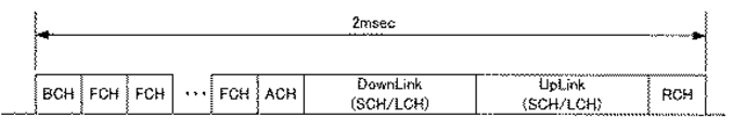
上記考察に基づいて、本発明の一実施の形態による通信技術について図面を参照して説明する。以下、5GHz帯の、MMAC(Multimedia Mobile Access Comminication)方式に本発明の実施の形態による通信技術を適用した例について説明する。MMAC方式では、無線基地局(以下、「基地局」、「AP」とも称する。)、無線端末局(以下、「端末」、「MT」とも称する。)間のデータの送受信は、2msのMAC(Media Access Control)フレーム単位で行なう。図1に示すように、1MACフレームは、BCHと、FCHと、ACHと、DownLinkと、UpLinkと、RCHと、の6つの物理チャネルを含んで構成されている。より詳細な構成例を図3に示す。
【0014】
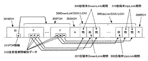
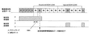
BCH301は、無線セル全体を考慮した制御情報を報知するチャネルであり、後続のFCH302やRCH306に関する送受信期間情報311を含んでいる。FCH302は、FCH302に続くMACフレームの構造を記述しているチャネルであり、後続の各端末宛のデータ送受信期間を指定する情報(送受信期間報知データ312)を含んでいる。ACH303は、前フレームのRCH(306)に対するACK情報を記載したチャネルである。DownLink304は、基地局からのデータ送信期間である。DownLink304は、自端末DownLink期間307と、他端末DownLink309とを含んでいる。UpLink305は、端末からのデータ送信期間である。UpLink305は、自端末UpLink期間308と、他端末UpLink310とを含んでいる。RCH306は、ランダムアクセス用のチャネルである。
【0015】
尚、DownLink304及びUpLink305は、 SCH、すなわちサイズの小さいデータ用の短いデータチャネルと、LCH、すなわち、サイズの大きいデータ用の長いデータチャネルとの2種類のデータチャンネルから構成されている。
【0016】
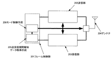
図2は、本実施の形態による端末の構成例を示す機能ブロック図である。図2に示す端末は、送信部202と、受信部203と、フレーム制御部201と、の3つのブロックに大別される。さらに、端末は、アンテナ204を含む。フレーム制御部201は、送受信期間報知データ取得手段205と、モード制御手段206とを含んでいる。
【0017】
図2に示す端末は、図6に示す「送信状態」であって、送信部がアクティブモード、受信部が省電力モードの「送信状態」と、図7に示す受信状態であって、送信部が省電力モード、受信部がアクティブモードの「受信状態」と、図8に示す休止状態であって、送信部、受信部ともに省電力モードの「休止状態」と、の3種類の状態を切替えることで、状況に応じて端末の省電力化を図ることができる。
【0018】
以下、図3に示す構成を有する信号を受信した場合を例にして、図2に示す通信端末の動作について図5を参照して説明する。適宜、他の図面も参照する。図5に示すように、ステップS501においてフレームが開始する。次に、ステップS502において、アンテナ204により受信された情報は、受信部203において、元の情報に復調される。復調されたデータは、フレーム制御部201内の送受信報知データ取得手段205により、フレームの属性分類処理、BCH301からFCH302の送信期間情報(FCH情報311)を取得する処理を経て、FCH302から、DownLink304及びUpLink305内の自端末の受信期間307と送信期間308との情報である送受信期間報知データ(BCH/FCH)を取得する。
【0019】
ステップS503において、ACHが必要か否かを判断する。ACHが有る場合にはステップS504において受信状態となり、その後にステップS505に進む。ACHが無い場合には、ステップS504を経ずにステップS505に進む。
【0020】
ステップS505のDownlinkにおいては、ステップS506において自端末宛の受信データが有るか否かを判定する。自端末宛の受信データが無い場合には、ステップ511に進み休止状態となる。自端末宛の受信データが有る場合には、ステップS507に進み、自端末のデータ受信期間であるか否かを判断する。自端末のデータ受信期間でない場合には、ステップS509に進み休止状態となる。自端末のデータ受信期間である場合には、ステップS508で受信状態となる。ステップS508の受信状態又はステップS509の休止状態から、ステップS510に進み、ステップS510においてDownlink終了状態であるか否かを判断する。Downlink終了状態でない場合には、ステップS507に戻る。Downlink終了状態である場合、又はステップS511の休止状態を経た場合に、ステップS512に進む。
【0021】
実際には、ステップS512内のステップS513において、自端末の送信データが有るか否かを判断する。自端末の送信データが無い場合には、ステップS518の休止状態に入る。自端末の送信データが有る場合には、ステップS514に進み、自端末のデータ送信期間であるか否かを判断する。自端末のデータ送信期間でない場合には、ステップS516に進み休止状態となる。自端末のデータ送信期間である場合には、ステップS515において送信状態となる。ステップS515又はステップS516を経て、ステップS517においてUplinkが終了したか否かを判断する。Uplinkが終了していなければ、ステップS514に戻る。Uplinkが終了したか、ステップS518の休止状態を経て、ステップS519に進む。ステップS519において、RCH送信を行うか否かを判断し、RCH送信を行う場合にはステップS520において送信状態になる。RCH送信を行わない場合、又は送信状態を経て、ステップS521においてフレームを終了する。
【0022】
すなわち、図4、図5に示すように、端末は、BCH:「受信状態」(ステップS502)、FCH:「受信状態」(ステップS502)、ACH:「受信状態」(ステップS504)、DownLink304:自端末を対象としたデータ期間:「受信状態」(ステップS508)、他の端末を対象としたデータ期間:「休止状態」(ステップS509)となる。UpLink305のうち、自端末を対象としたデータ期間:「送信状態」(ステップS515)、他の端末を対象としたデータ期間:「休止状態」(ステップS516)、RCH:「送信状態」(ステップS520)となる。このように、フレームのチャンネルとその内容とに応じて、端末の動作状態を変化させることができる。
尚、「休止状態」から「受信状態」、「送信状態」に移行する際の、回路動作の安定に必要な時間を見込んで送受信期間報知データから得た時刻より「受信状態」、「送信状態」の開始時間が早くなるように設定しても良い。
【0023】
次に、本発明の第2の実施の形態による通信技術について図面を参照して説明する。図9は、図5のステップS505(DownLink)に示す処理の流れを変更した例を示す図である。本実施の形態による通信技術は、モード制御手段に、送受信期間報知データの解析完了を確認する手段が設けられ、送受信期間報知データの解析完了の有無をモード切替えの選択条件とし、送受信期間報知データの解析完了まで「受信状態」を維持するモード切替え判定手段を備え、図2の通信端末のモード切替えが、図10に示すように、DownLink:自端末を対象としたデータ期間の有無に関係なく、少なくとも送受信期間報知データの解析完了まで「受信状態」となっている。
【0024】
図9に示すように、ステップS901において、送受信期間情報報知データ解析が完了したか否かを判断する。送受信期間情報報知データ解析が完了していなければ、ステップS911に進み、受信状態を維持する。送受信期間情報報知データ解析が完了していれば、ステップS902に進み、自端末宛受信期間か否かを判断する。自端末宛受信期間であれば、ステップS903において受信状態を維持する。自端末宛受信期間でなければ、ステップS904に進み、休止状態となる。その後、ステップS905に進み、自端末受信データが有るか否かを判断する。自端末受信データが無ければ、ステップS910に進み休止状態となる。
【0025】
自端末受信データがあれば、ステップS906において自端末のデータ受信期間であるか否かを判断する。自端末のデータ受信期間であれば、ステップS907に進み、受信状態となる。自端末のデータ受信期間でなければ、ステップS908に進み、休止状態となる。その後、ステップS909に進み、Downlinkが終了したか否かを判断する。Downlinkが終了していなければ、ステップS906に戻る。Downlinkが終了した状態又はステップS910の休止状態を経て、図5のステップS512に進む。
【0026】
本実施の形態による通信技術によれば、DownLink開始時期までに送受信期間報知データの解析が完了しなかった場合に、少なくとも送受信期間報知データの解析完了までのDownLinkを「受信状態」とすることにより、自端末向けデータが受信できなくなる、いわゆる「取りこぼし」の発生を回避することができる。(図10の符号1001参照)。
【0027】
次に、本発明の第3の実施の形態による通信技術について図面を参照して説明する。図11は、本実施の形態による通信技術の流れのうち第1の実施の形態による処理の流れを示す図5におけるステップS504の処理の流れの別の例を示す図である。図12は、本実施の形態による通信技術の流れのうち図5のステップS512の処理の流れの別の例を示す図である。すなわち、本実施の形態による通信技術では、図5のステップS505(DownLink)とステップS512(UpLink)とが、第1の実施の形態による処理と異なっている。
【0028】
図11から図13に示すように、Downlinkでは、ステップS1101において、自端末宛のデータがあるか否かを判断する。自端末宛のデータがない場合には、ステップS1111において端末は休止状態に入る。自端末宛のデータが有る場合には、ステップS1102に進み、図13に示すRx1とX1とを比較する。Rx1>X1の場合には、ステップS1103に進み、Rx1期間休止状態に入る。Rx1>X1でない場合は、ステップS1104に進み、Rx1期間受信状態となる。その後、ステップS1103又はステップS1104からステップS1105に進み、自端末宛のデータ受信期間であるか否かを判断する。自端末宛のデータ受信期間でなければ、ステップS1111に進み、端末は休止状態に入る。ステップS1105において、自端末宛のデータ受信期間であると判断された場合には、ステップS1106において受信状態に入る。次いで、ステップS1107において自端末宛のデータが有るか否かを判断する。自端末宛のデータがない場合には、ステップS1111に進み、端末は休止状態に入る。ステップS1107において自端末宛のデータが有ると判断された場合には、ステップS1108に進み、Rx2>x2であるか否かを判断する。Rx2>x2である場合には、ステップS1109に進み、Rx2期間端末は休止状態に入る。Rx2>x2でないと判断された場合には、ステップS1110に進み、Rx2受信状態になる。ステップS1109、ステップS1110に次いで、ステップS1105に戻り、以下自端末のデータ受信期間中は受信動作を繰り返す。
【0029】
図12に示すように、Uplinkでは、ステップS1201において自端末の送信データが有るか否かを判断する。自端末の送信データがない場合には、ステップS1212に進み休止状態になる。自端末の送信データがない場合には、ステップS1212に進み、自端末のデータ送信期間であるか否かを判断する。自端末のデータ送信期間でない場合には、ステップS1204に進み端末が休止状態に入る。自端末のデータ送信期間である場合には、ステップS1203に進み、送信状態となる。次いで、ステップS1205に進み、Tx1>x3であるか否かを判断する。Tx1>x3であれば、ステップS1206に進み、端末は、Tx1期間休止状態に入る。Tx1<x3であれば、ステップS1207に進み、Tx1送信状態になる。ステップS1204、ステップS1206又はステップS1207から、ステップS1208に進み、最後の送信データであるか否かを判断する。最後の送信データでなければ、ステップS1202に戻る。ステップS1208で、最後の送信データであると判断されれば、ステップS1209に進み、Tx2>x4であるか否かを判断する。Tx2>x4でなければ、ステップS1211に進み、Tx2送信状態となる。Tx2>x4であれば、ステップS1210に進みTx2休止状態となる。ステップS1210又はS1211から、図5のステップS519に進む。
【0030】
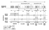
本実施の形態による通信装置は、上述のように、モード制御手段に送受信期間報知データの解析完了を確認する手段と、送受信期間報知データの解析完了の有無を、モード切替えの選択条件としたモード切替え判定手段とを備えている。DownLink或いはUpLinkにおいて、自端末に割り当てられた通信時間(以下、「自」とも記載する。)と、他端末に割り当てられた通信時間宛(以下、「他」とも記載する。)が、短い時間間隔で「他、他、自、他、自、他」と混在する場合であって、図2に示す通信端末の動作モードが、図13に示すように、DownLink:DownLink開始時点から、自端末宛ての第1のデータ期間開始までの時間(Rx1)が予め設定した第1の閾値X1以下の場合は、ACH(ACHがない場合はFCH)と前記第1のデータ期間終了までの間「受信状態」を維持する。自端末宛ての第n(nは自然数)のデータ期間と第n+1のデータ期間に挟まれた他端末宛てのデータ期間(Rx2)の長さが予め設定した第2の閾値X2以下の場合は、少なくとも第nのデータ期間の開始から第n+1のデータ期間終了までの間「受信状態」を維持する。
【0031】
UpLinkにおいて、自端末に割り当てられた第nの送信期間と第n+1の送信期間に挟まれた他端末に割り当てられた送信期間(Tx1)の長さが、予め設定した閾値X3以下の場合は、少なくとも第nの送信期間の開始から第n+1の送信期間終了までの間「送信状態」を維持する。
【0032】
UpLinkにおける自端末に割り当てられた最後の送信期間とRCH送信期間との間に挟まれた他端末に割り当てられた送信期間(Tx2)の長さが予め設定した閾値X4以下の場合は、少なくともUpLink最後の自端末送信期間の開始からRCH送信期間終了までの間「送信状態」を維持する。
【0033】
本実施の形態による送信技術を用いると、短い時間間隔での動作モードの切替わりを抑制し、短い時間間隔での動作モードの切替えによって生じるシステムの不安定になるのを回避することができる。
【0034】
ここで、本発明の実施の形態による通信技術を用いる利点について、図14、15及び表1に基づいて簡単な試算を行う。各部のそれぞれの場合の平均消費電力を以下のように仮定する(詳細は表1に示す通りである。)。送信状態における消費電力が3.4W、受信状態における消費電力が2.6W、休止状態における消費電力が1.0Wとする。加えて、図14、15に示すように、ACHの送信が有り、RCHの受信が有り、Downlinkにおける自端末宛のデータが1区間の受信であり、Uplinkにおける1区間の送信で有る場合を考える。
【0035】
【表1】

T1=900μsec、T2=900μsec、T3=199.1μsec、T4=889.2μsec、T5=5.4μsec、T6=452.7μsec、T7=5.4μsec、T8=447.3μsec、T9=0.9μsecとすると、従来技術を用いた通信技術(図14)を用いると、消費電力は1.05μWhと見積もることができる。一方、本発明の実施の形態による通信技術(図15)を用いると、消費電力は0.65μWhとなり、約37.8%の消費電力削減を図ることができる。
加えて、本実施の形態による無線技術では、例えば特に図2の送信部202は、通電する積算時間が短くなるため、製品寿命が長くなる利点もある。
【0037】
以上、本実施の形態に沿って説明したが、本発明はこれらの例に限定されるものではなく、種々の変形が可能であるのは言うまでもない。本実施の形態による通信技術は、無線・有線を問わず各種通信装置に応用することができる。
【0038】
【発明の効果】
本発明の通信技術を用いると、安定した送受信を確保しつつ、通信装置の省電力が可能となる。
【図面の簡単な説明】
【図1】本発明の第1の実施の形態による通信技術において用いられる1フレームの通信データ構成例を示す図である。
【図2】本発明の第1の実施の形態による通信技術において用いられる通信端末の概略構成を示す機能ブロック図である。
【図3】本発明の第1の実施の形態による通信技術における1MACフレームのより詳細な構成例を示す図である。
【図4】本発明の第1の実施の形態による通信技術における無線基地局と、端末局とのそれぞれの通信状態例を示す図である。
【図5】本発明の第1の実施の形態による通信技術における処理の流れを示すフローチャート図である。
【図6】図2に対応する図であって、受信部が省電力モードとなっている状態を示す図である。
【図7】図2に対応する図であって、送信部が省電力モードとなっている状態を示す図である。
【図8】図2に対応する図であって、全体が省電力モードとなっている状態を示す図である。
【図9】本発明の第2の実施の形態による通信技術における処理の流れを示すフローチャート図の一部であり、図5のDownlinkにおける処理の流れを変更した図である。
【図10】本発明の第2の実施の形態による通信技術における無線基地局と、端末局とのそれぞれの通信状態例を示す図である。
【図11】本発明の第3の実施の形態による通信技術における処理の流れを示すフローチャート図の一部であり、図5のDownlinkにおける処理の流れを変更した図である。
【図12】本発明の第3の実施の形態による通信技術における処理の流れを示すフローチャート図の一部であり、図5のUplinkにおける処理の流れを変更した図である。
【図13】本発明の第3の実施の形態による通信技術における無線基地局と、端末局とのそれぞれの通信状態例を示す図である。
【図14】一般的な通信技術における無線基地局と、端末局とのそれぞれの通信状態例を示す図である。
【図15】本発明の実施の形態による通信技術における無線基地局と、端末局とのそれぞれの通信状態例を示す図である。
【符号の説明】
201…フレーム制御部、202…送信部、203…受信部、204…アンテナ、205…送受信期間報知データ取得手段、206…モード制御手段。[0001]
TECHNICAL FIELD OF THE INVENTION
The present invention relates to a communication device, and more particularly to a technology for saving power of a communication device.
[0002]
[Prior art]
There has been a remarkable development in communication devices, particularly portable wireless communication devices, with higher functionality. In order to extend the life of a battery that is a power supply source of a portable wireless communication device (hereinafter, referred to as a “terminal”), power saving is required. In general, power saving technologies generally used in terminals are roughly classified into the following two technologies. 1) The power consumption of a circuit used for signal processing or the like is reduced. 2) A sleep mode technology employed in a notebook personal computer or the like, for example, a technology in which the device is operated only when necessary, and in which the operation of the device is stopped at other times, is used.
[0003]
Patent Literature 1 describes, as a technique related to the above 2), an example in which the technique is applied to a communication terminal that performs data communication in frame units. The terminal described in Patent Document 1 determines the presence or absence of data addressed to its own terminal from the destination data stored at the beginning of the frame, and the data addressed to its own terminal is included in the destination data stored at the beginning. If there is no frame, the power of the receiving unit is turned off in that frame, and power is not supplied until the start time of the next frame. If the destination includes the data addressed to the own terminal, the power of the receiving unit is turned off after the reception of the data addressed to the own terminal is completed. Thus, the power consumption of the receiving unit is reduced.
[Patent Document 1]
JP-A-6-311160
[0004]
[Problems to be solved by the invention]
However, in the above prior art, a frame having data addressed to the own terminal is subjected to reception processing from the beginning of the frame to data addressed to the own terminal, so that the terminal can receive even data transmission periods other than the own terminal. It is necessary to maintain the state. When the power of the receiver is supplied (the power is turned on) for the time during which the data addressed to the own station is transmitted in the frame, the power of the receiver is repeatedly turned on and off frequently, and the operation of the receiver becomes unstable. Further, in general, current flows into the circuit when shifting from the power saving mode operation to the active mode operation, so that the power consumption may be increased as compared with the normal mode in which the operation is continuously performed. If the power of the transmission / reception unit is turned off, it takes time until the next activation, and there is a case where the transmission / reception timing cannot be met.
An object of the present invention is to provide a communication technique capable of achieving both stable operation and power saving.
[0005]
[Means for Solving the Problems]
According to one aspect of the present invention, the base station includes a base station and a terminal station, wherein the base station periodically transmits communication period control data specifying a transmission / reception period of the terminal station, and the terminal station performs the communication period control. A first period for receiving the communication period control data, and a second period for a data reception period and a data transmission period allocated to the own terminal, which are suitable for use in a communication system for performing communication based on data. Is an active mode, and is in a power saving mode during a third period other than the first and second periods.
[0006]
It is preferable that at least the reception unit related to reception maintains the active mode state from the time when the communication period control data is received until the calculation of the reception period included in the communication period control data is completed.
[0007]
It is preferable that at least the transmission unit related to transmission maintains the active mode state from the time when the communication period control data is received to the time when the calculation of the transmission period included in the communication period control data is completed. Alternatively, it is preferable that the receiving unit for receiving the transmission period maintain the active mode state.
By preventing the power saving mode from being set before the calculation of the reception period included in the communication period control data is completed, it is possible to prevent the actual communication from becoming unstable.
[0008]
If the reception periods obtained from the communication period control data are distributed over a plurality of time zones, and if the interval between adjacent time zones is within a first interval, Preferably, the unit does not shift to the power saving mode between the adjacent time zones. Further, when the transmission period obtained from the communication period control data is distributed over a plurality of time zones, and when the interval between the adjacent time zones is within a second interval, It is preferable that the transmitting unit does not shift to the power saving mode between the adjacent time zones.
[0009]
At this time, as described above, current flows into the circuit when shifting from the power saving mode operation to the active mode operation, so that the power consumption increases rather than in the normal mode in which the operation is continuously performed. Sometimes. In such a case, it is necessary to at least expect a reduction in power consumption as compared with the case where the active mode operation is continuously performed. When shifting from the active mode operation to the power saving mode operation, it is not necessary to consider an increase in power consumption. In this way, it is possible to prevent an increase in power consumption due to frequent switching between the power saving mode and the active mode.
[0010]
BEST MODE FOR CARRYING OUT THE INVENTION
In this specification, the active mode refers to an operation state for performing continuous transmission or continuous reception. The power saving mode is an operation state in which when there is no need to transmit or receive, the power of each module is stopped, the operating frequency is reduced, or the power supply voltage or current is reduced to reduce power consumption. To tell. There may be a case where a plurality of operation states are set instead of a single operation state. How much power consumption can be reduced by them is indicated by a power saving level described later. The power saving level is an index indicating the magnitude of power consumption. For example, an operation state in which the power saving level is higher requires a longer time to shift to the active mode but consumes less power. Conversely, an operation state in which the power saving level is lower shifts to the active mode faster, Power consumption is greater.
In other words, if the power saving level is large, the power consumption is small, but the time required for transition to the active mode is long. If the power saving level is small, the power consumption is large, but the time required for transition to the active mode is short.
[0011]
Before describing embodiments of the present invention, considerations made by the inventor will be described first. The inventor uses the destination information stored at the beginning of the frame and the position (timing) information of the data addressed to the terminal to determine whether there is data addressed to the own terminal, and to transmit the data addressed to the own terminal from the beginning of the frame. Data that specifies a period is extracted, and based on this data, it has been conceived that the receiving unit operates only during the transmission period of the data addressed to the own terminal in the frame. By analyzing the extracted data, if the time to be transmitted or received by the own terminal is finely dispersed, by continuously transmitting or receiving, control to receive only the data addressed to the own terminal is performed. At the same time, power consumption can be reduced by reducing the change in the operation state.
[0012]
Further, by setting a plurality of power saving operation modes having different recovery required times until a normal transmission / reception operation, the power saving operation mode can be selected according to the length of a data transmission period other than the one addressed to the own terminal. Fine power saving control can be performed. If a mode capable of shifting to the transmission operation state or the reception operation state at a high speed is selected, power can be saved while ensuring stable transmission and reception.
[0013]
Based on the above considerations, a communication technique according to an embodiment of the present invention will be described with reference to the drawings. Hereinafter, an example in which the communication technology according to the embodiment of the present invention is applied to a 5 GHz band MMAC (Multimedia Mobile Access Communication) method will be described. In the MMAC method, data transmission and reception between a radio base station (hereinafter, also referred to as “base station” and “AP”) and a radio terminal station (hereinafter, also referred to as “terminal” and “MT”) are performed by using a 2 ms MAC. (Media Access Control) This is performed in frame units. As shown in FIG. 1, one MAC frame is configured to include six physical channels of BCH, FCH, ACH, DownLink, UpLink, and RCH. FIG. 3 shows a more detailed configuration example.
[0014]
The BCH 301 is a channel that broadcasts control information considering the entire radio cell, and includes transmission / reception period information 311 relating to the subsequent FCH 302 and RCH 306. The FCH 302 is a channel describing the structure of a MAC frame following the FCH 302, and includes information (transmission / reception period notification data 312) specifying a data transmission / reception period for each subsequent terminal. The ACH 303 is a channel describing ACK information for the RCH (306) of the previous frame. DownLink 304 is a data transmission period from the base station. DownLink 304 includes own terminal DownLink period 307 and other terminal DownLink 309. UpLink 305 is a data transmission period from the terminal. The UpLink 305 includes the own terminal UpLink period 308 and another terminal UpLink 310. RCH 306 is a channel for random access.
[0015]
The DownLink 304 and the UpLink 305 are composed of two types of data channels: an SCH, that is, a short data channel for small-sized data, and an LCH, that is, a long data channel for large-sized data.
[0016]
FIG. 2 is a functional block diagram showing a configuration example of the terminal according to the present embodiment. The terminal illustrated in FIG. 2 is roughly divided into three blocks: a
[0017]
The terminal shown in FIG. 2 is in the “transmission state” shown in FIG. 6, in which the transmitting unit is in the “transmission state” in the active mode and the receiving unit is in the power saving mode, and in the receiving state shown in FIG. Switches between three types of states: a power saving mode, a receiving unit in an active mode, a “reception state”, and a sleep state shown in FIG. 8, in which both the transmitting unit and the receiving unit are in a power saving mode, “pause state”. Thus, power saving of the terminal can be achieved depending on the situation.
[0018]
Hereinafter, the operation of the communication terminal shown in FIG. 2 will be described with reference to FIG. 5, taking as an example a case where a signal having the configuration shown in FIG. 3 is received. Reference is made to other drawings as appropriate. As shown in FIG. 5, a frame starts in step S501. Next, in step S502, the information received by the antenna 204 is demodulated into the original information in the receiving unit 203. The demodulated data is transmitted from the FCH 302 to the DownLink 304 and from the FCH 302 through the transmission / reception broadcast data acquisition unit 205 in the frame control unit 201 through the frame attribute classification process and the process of acquiring the transmission period information (FCH information 311) of the FCH 302 from the BCH 301. The transmission / reception period notification data (BCH / FCH), which is information on the reception period 307 and the transmission period 308 of the own terminal in the UpLink 305, is acquired.
[0019]
In step S503, it is determined whether the ACH is necessary. If there is an ACH, the reception state is set in step S504, and thereafter, the process proceeds to step S505. If there is no ACH, the process proceeds to step S505 without passing through step S504.
[0020]
In Downlink in step S505, it is determined in step S506 whether or not there is received data addressed to the own terminal. If there is no received data addressed to the own terminal, the process proceeds to step 511 and enters a sleep state. If there is received data addressed to the own terminal, the process proceeds to step S507, and it is determined whether or not it is the data receiving period of the own terminal. If the period is not the data reception period of the own terminal, the process proceeds to step S509 and enters a sleep state. If it is the data reception period of the own terminal, the reception state is set in step S508. From the reception state of step S508 or the pause state of step S509, the process proceeds to step S510, and it is determined whether or not the Downlink end state is set in step S510. If the Downlink end state has not been reached, the process returns to step S507. If it is in the Downlink end state, or if it has passed through the sleep state in step S511, the process proceeds to step S512.
[0021]
Actually, in step S513 in step S512, it is determined whether or not there is transmission data of the own terminal. If there is no transmission data of the own terminal, the process enters a sleep state of step S518. If there is transmission data of the own terminal, the process proceeds to step S514, and it is determined whether it is the data transmission period of the own terminal. If it is not the data transmission period of the terminal itself, the process proceeds to step S516 and enters the sleep state. If it is the data transmission period of the own terminal, the transmission state is set in step S515. After step S515 or step S516, it is determined in step S517 whether Uplink has been completed. If Uplink has not been completed, the process returns to step S514. After the Uplink is completed, or after the sleep state of step S518, the process proceeds to step S519. In step S519, it is determined whether or not to perform RCH transmission. If RCH transmission is to be performed, a transmission state is set in step S520. When the RCH transmission is not performed or after the transmission state, the frame ends in step S521.
[0022]
That is, as shown in FIG. 4 and FIG. 5, the terminal sets BCH: “Reception state” (step S502), FCH: “Reception state” (step S502), ACH: “Reception state” (step S504), DownLink 304: The data period for the own terminal: “reception state” (step S508), and the data period for other terminals: “pause state” (step S509). Of the UpLink 305, a data period for its own terminal: “transmission state” (step S515), a data period for another terminal: “pause state” (step S516), RCH: “transmission state” (step S520) ). As described above, the operation state of the terminal can be changed according to the frame channel and the content thereof.
When transitioning from the "pause state" to the "reception state" or the "transmission state", the "reception state", "transmission state" May be set to be earlier.
[0023]
Next, a communication technique according to a second embodiment of the present invention will be described with reference to the drawings. FIG. 9 is a diagram showing an example in which the flow of the process shown in step S505 (DownLink) of FIG. 5 is changed. In the communication technology according to the present embodiment, the mode control means is provided with means for confirming the completion of analysis of the transmission / reception period notification data, and the presence / absence of completion of the analysis of the transmission / reception period notification data is set as a mode switching selection condition. The mode switching of the communication terminal shown in FIG. 2 is performed as shown in FIG. 10, regardless of whether or not there is a data period for the own terminal, as shown in FIG. , At least until the analysis of the transmission / reception period notification data is completed.
[0024]
As shown in FIG. 9, in step S901, it is determined whether or not the transmission / reception period information notification data analysis has been completed. If the transmission / reception period information notification data analysis has not been completed, the process proceeds to step S911, and the reception state is maintained. If the transmission / reception period information notification data analysis has been completed, the process proceeds to step S902, and it is determined whether or not the reception period is for the own terminal. If the reception period is for the own terminal, the reception state is maintained in step S903. If it is not the reception period for the own terminal, the process proceeds to step S904, and the terminal enters a sleep state. Thereafter, the process proceeds to step S905, and it is determined whether or not the own terminal received data exists. If there is no own terminal reception data, the process proceeds to step S910 and enters a sleep state.
[0025]
If there is the own terminal reception data, it is determined in step S906 whether or not it is the data reception period of the own terminal. If it is the data reception period of the own terminal, the process proceeds to step S907 to enter the reception state. If it is not the data reception period of the own terminal, the process proceeds to step S908, and the terminal enters a sleep state. After that, the process advances to step S909 to determine whether the Downlink has been completed. If the Downlink has not been completed, the process returns to step S906. The process proceeds to step S512 in FIG. 5 via the state in which the Downlink has ended or the pause state in step S910.
[0026]
According to the communication technology according to the present embodiment, when the analysis of the transmission / reception period notification data is not completed by the start of the DownLink, at least the DownLink until the analysis of the transmission / reception period notification data is completed is set to the “receiving state”. In addition, it is possible to avoid the occurrence of so-called “missing” in which data for the terminal cannot be received. (See reference numeral 1001 in FIG. 10).
[0027]
Next, a communication technique according to a third embodiment of the present invention will be described with reference to the drawings. FIG. 11 is a diagram illustrating another example of the processing flow of step S504 in FIG. 5 illustrating the processing flow according to the first embodiment of the communication technology flow according to the present embodiment. FIG. 12 is a diagram showing another example of the flow of the process of step S512 in FIG. 5 in the flow of the communication technology according to the present embodiment. That is, in the communication technique according to the present embodiment, step S505 (DownLink) and step S512 (UpLink) in FIG. 5 are different from the processing according to the first embodiment.
[0028]
As shown in FIGS. 11 to 13, in Downlink, in step S1101, it is determined whether there is data addressed to the terminal itself. If there is no data addressed to the own terminal, the terminal enters a sleep state in step S1111. If there is data addressed to the own terminal, the process advances to step S1102 to compare Rx1 and X1 shown in FIG. If Rx1> X1, the process advances to step S1103 to enter the sleep state for the Rx1 period. If Rx1> X1 is not satisfied, the process proceeds to step S1104, and the reception state is set for the Rx1 period. After that, the process advances from step S1103 or step S1104 to step S1105 to determine whether or not it is a data reception period addressed to the terminal. If it is not the data reception period addressed to the own terminal, the process proceeds to step S1111 and the terminal enters a sleep state. If it is determined in step S1105 that the data reception period is the data reception period addressed to the own terminal, the process enters a reception state in step S1106. Next, in step S1107, it is determined whether there is data addressed to the terminal itself. If there is no data addressed to the own terminal, the process proceeds to step S1111 and the terminal enters a sleep state. If it is determined in step S1107 that there is data addressed to the own terminal, the process advances to step S1108 to determine whether Rx2> x2. If Rx2> x2, the process proceeds to step S1109, and the terminal enters a dormant state for an Rx2 period. If it is determined that Rx2> x2 is not satisfied, the process proceeds to step S1110, and the Rx2 reception state is set. After step S1109 and step S1110, the process returns to step S1105, and the receiving operation is repeated during the data receiving period of the own terminal.
[0029]
As shown in FIG. 12, in Uplink, in step S1201, it is determined whether or not there is transmission data of the own terminal. If there is no transmission data of the own terminal, the process proceeds to step S1212 to enter a sleep state. If there is no transmission data of the own terminal, the process advances to step S1212 to determine whether or not it is the data transmission period of the own terminal. If it is not the data transmission period of the terminal itself, the process proceeds to step S1204, and the terminal enters a sleep state. If it is the data transmission period of the own terminal, the process proceeds to step S1203 to enter the transmission state. Next, the process proceeds to step S1205, and it is determined whether or not Tx1> x3. If Tx1> x3, the process proceeds to step S1206, and the terminal enters a sleep state for a period of Tx1. If Tx1 <x3, the process proceeds to step S1207 to enter the Tx1 transmission state. From step S1204, step S1206, or step S1207, the process proceeds to step S1208 to determine whether the data is the last transmission data. If it is not the last transmission data, the process returns to step S1202. If it is determined in step S1208 that the data is the last transmission data, the process advances to step S1209 to determine whether Tx2> x4. If Tx2> x4 is not satisfied, the process proceeds to step S1211 to enter the Tx2 transmission state. If Tx2> x4, the process proceeds to step S1210 and enters the Tx2 sleep state. From step S1210 or S1211, the process proceeds to step S519 in FIG.
[0030]
As described above, the communication apparatus according to the present embodiment includes a mode control unit that confirms the completion of analysis of transmission / reception period notification data, and a mode in which the presence / absence of analysis of transmission / reception period notification data is selected as a mode switching selection condition. Switching determination means. In DownLink or UpLink, the communication time allocated to the own terminal (hereinafter, also referred to as “own”) and the communication time allocated to another terminal (hereinafter, also referred to as “other”) are short. In the case where “other, other, own, other, own, other” is mixed at intervals, the operation mode of the communication terminal shown in FIG. 2 is, as shown in FIG. 13, DownLink: from the start of the DownLink to the own terminal. When the time (Rx1) until the start of the first data period addressed to the destination is equal to or less than the first threshold X1 set in advance, the “reception” is performed between the ACH (FCH if there is no ACH) and the end of the first data period. State. " If the length of the data period (Rx2) between the n-th (n is a natural number) data period addressed to the own terminal and the (n + 1) -th data period addressed to the other terminal is equal to or less than a second threshold value X2 set in advance, The “receiving state” is maintained at least from the start of the n-th data period to the end of the (n + 1) -th data period.
[0031]
In UpLink, when the length of the transmission period (Tx1) allocated to the other terminal between the n-th transmission period allocated to the own terminal and the (n + 1) -th transmission period is equal to or less than a preset threshold X3, The “transmission state” is maintained at least from the start of the n-th transmission period to the end of the (n + 1) -th transmission period.
[0032]
If the length of the transmission period (Tx2) allocated to the other terminal between the last transmission period allocated to the own terminal and the RCH transmission period in UpLink is equal to or less than a preset threshold X4, at least UpLink The “transmission state” is maintained from the start of the last terminal transmission period to the end of the RCH transmission period.
[0033]
When the transmission technique according to the present embodiment is used, switching of operation modes at short time intervals can be suppressed, and system instability caused by switching of operation modes at short time intervals can be avoided.
[0034]
Here, a simple trial calculation of the advantage of using the communication technology according to the embodiment of the present invention will be made based on FIGS. The average power consumption in each case of each unit is assumed as follows (details are shown in Table 1). Assume that the power consumption in the transmission state is 3.4 W, the power consumption in the reception state is 2.6 W, and the power consumption in the pause state is 1.0 W. In addition, as shown in FIGS. 14 and 15, consider a case where ACH is transmitted, RCH is received, data addressed to the own terminal in Downlink is reception in one section, and transmission is one section in Uplink. .
[0035]
[Table 1]
T1 = 900 μsec, T2 = 900 μsec, T3 = 199.1 μsec, T4 = 889.2 μsec, T5 = 5.4 μsec, T6 = 452.7 μsec, T7 = 5.4 μsec, T8 = 447.3 μsec, T9 = 0.9 μsec. Then, when the communication technology using the conventional technology (FIG. 14) is used, the power consumption can be estimated to be 1.05 μWh. On the other hand, when the communication technology (FIG. 15) according to the embodiment of the present invention is used, the power consumption is 0.65 μWh, and the power consumption can be reduced by about 37.8%.
In addition, in the wireless technology according to the present embodiment, for example, especially, the
[0037]
Although the embodiments have been described above, the present invention is not limited to these examples, and it goes without saying that various modifications are possible. The communication technology according to the present embodiment can be applied to various communication devices regardless of wireless or wired.
[0038]
【The invention's effect】
The use of the communication technology of the present invention enables the communication device to save power while ensuring stable transmission and reception.
[Brief description of the drawings]
FIG. 1 is a diagram showing an example of a configuration of communication data of one frame used in a communication technique according to a first embodiment of the present invention.
FIG. 2 is a functional block diagram illustrating a schematic configuration of a communication terminal used in the communication technology according to the first embodiment of the present invention.
FIG. 3 is a diagram illustrating a more detailed configuration example of one MAC frame in the communication technique according to the first embodiment of the present invention.
FIG. 4 is a diagram illustrating an example of respective communication states between a wireless base station and a terminal station in the communication technology according to the first embodiment of the present invention.
FIG. 5 is a flowchart illustrating a flow of a process in the communication technique according to the first embodiment of the present invention.
FIG. 6 is a diagram corresponding to FIG. 2, showing a state in which the receiving unit is in a power saving mode.
FIG. 7 is a diagram corresponding to FIG. 2, showing a state in which the transmission unit is in a power saving mode.
FIG. 8 is a diagram corresponding to FIG. 2, showing a state in which the whole is in a power saving mode.
FIG. 9 is a part of a flowchart showing a processing flow in the communication technique according to the second embodiment of the present invention, and is a diagram in which the processing flow in Downlink in FIG. 5 is changed.
FIG. 10 is a diagram illustrating an example of respective communication states between a wireless base station and a terminal station in the communication technology according to the second embodiment of the present invention.
FIG. 11 is a part of a flowchart showing a flow of processing in the communication technique according to the third embodiment of the present invention, and is a diagram in which the flow of processing in Downlink in FIG. 5 is modified.
FIG. 12 is a part of a flowchart showing a flow of processing in the communication technology according to the third embodiment of the present invention, and is a diagram in which the flow of processing in Uplink in FIG. 5 is modified.
FIG. 13 is a diagram illustrating an example of respective communication states between a wireless base station and a terminal station in the communication technology according to the third embodiment of the present invention.
FIG. 14 is a diagram illustrating an example of respective communication states between a wireless base station and a terminal station in a general communication technique.
FIG. 15 is a diagram illustrating an example of respective communication states between a wireless base station and a terminal station in the communication technology according to the embodiment of the present invention.
[Explanation of symbols]
201: frame control unit, 202: transmission unit, 203: reception unit, 204: antenna, 205: transmission / reception period notification data acquisition unit, 206: mode control unit.
Claims (14)
前記通信期間制御データを受信する第1の期間と、自端末に割り当てられたデータ受信期間及びデータ送信期間である第2の期間は、アクティブモードとなり、前記第1及び第2の期間以外の第3の期間は省電力モードとなることを特徴とする端末局。A communication system including a base station and a terminal station, wherein the base station periodically transmits communication period control data specifying a transmission / reception period of the terminal station, and wherein the terminal station performs communication based on the communication period control data. Suitable for use in
A first period for receiving the communication period control data and a second period, which is a data reception period and a data transmission period allocated to the own terminal, are in an active mode, and the second period other than the first and second periods is in an active mode. A terminal station wherein the terminal station is in a power saving mode during a period of 3.
前記端末局は、前記通信期間制御データを受信する第1の期間と、自端末に割り当てられたデータ受信期間及びデータ送信期間である第2の期間は、アクティブモードとなり、前記第1及び第2の期間以外の第3の期間は省電力モードとなることを特徴とする通信システム。A communication system including a base station and a terminal station, wherein the base station periodically transmits communication period control data specifying a transmission / reception period of the terminal station, and wherein the terminal station performs communication based on the communication period control data. And
The terminal station is in an active mode during a first period during which the communication period control data is received and a second period that is a data reception period and a data transmission period allocated to the terminal itself. A communication period in a power saving mode during a third period other than the period.
Priority Applications (1)
| Application Number | Priority Date | Filing Date | Title |
|---|---|---|---|
| JP2002263695A JP2004104465A (en) | 2002-09-10 | 2002-09-10 | Communication device and terminal station |
Applications Claiming Priority (1)
| Application Number | Priority Date | Filing Date | Title |
|---|---|---|---|
| JP2002263695A JP2004104465A (en) | 2002-09-10 | 2002-09-10 | Communication device and terminal station |
Publications (2)
| Publication Number | Publication Date |
|---|---|
| JP2004104465A true JP2004104465A (en) | 2004-04-02 |
| JP2004104465A5 JP2004104465A5 (en) | 2005-10-20 |
Family
ID=32263343
Family Applications (1)
| Application Number | Title | Priority Date | Filing Date |
|---|---|---|---|
| JP2002263695A Pending JP2004104465A (en) | 2002-09-10 | 2002-09-10 | Communication device and terminal station |
Country Status (1)
| Country | Link |
|---|---|
| JP (1) | JP2004104465A (en) |
Cited By (5)
| Publication number | Priority date | Publication date | Assignee | Title |
|---|---|---|---|---|
| JP2006295370A (en) * | 2005-04-07 | 2006-10-26 | Hitachi Communication Technologies Ltd | Wireless communication terminal and management method of transmission/reception function |
| US7391746B2 (en) | 2004-06-28 | 2008-06-24 | Nec Corporation | Power saving method in wireless LAN system for permitting terminal station to promptly transition to doze state by transmitting empty data frame |
| JP2009147835A (en) * | 2007-12-18 | 2009-07-02 | Kenwood Corp | Feeding method in receiver and transmitter |
| JPWO2008050574A1 (en) * | 2006-10-23 | 2010-02-25 | シャープ株式会社 | Mobile communication system, mobile communication method, base station apparatus, and mobile station apparatus |
| US9572082B2 (en) | 2014-03-14 | 2017-02-14 | Fujitsu Limited | Method for digital communication, radio communication system, and radio communication apparatus |
-
2002
- 2002-09-10 JP JP2002263695A patent/JP2004104465A/en active Pending
Cited By (9)
| Publication number | Priority date | Publication date | Assignee | Title |
|---|---|---|---|---|
| US7391746B2 (en) | 2004-06-28 | 2008-06-24 | Nec Corporation | Power saving method in wireless LAN system for permitting terminal station to promptly transition to doze state by transmitting empty data frame |
| JP2006295370A (en) * | 2005-04-07 | 2006-10-26 | Hitachi Communication Technologies Ltd | Wireless communication terminal and management method of transmission/reception function |
| JP4651440B2 (en) * | 2005-04-07 | 2011-03-16 | 株式会社日立製作所 | Wireless communication terminal and method for managing transmission / reception function thereof |
| JPWO2008050574A1 (en) * | 2006-10-23 | 2010-02-25 | シャープ株式会社 | Mobile communication system, mobile communication method, base station apparatus, and mobile station apparatus |
| JP2011061841A (en) * | 2006-10-23 | 2011-03-24 | Sharp Corp | Mobile communication system, mobile communication method, base station and mobile station device |
| US8711879B2 (en) | 2006-10-23 | 2014-04-29 | Sharp Kabushiki Kaisha | Radio communication system, base station device and mobile station device utilizing an intermittent reception |
| USRE47587E1 (en) | 2006-10-23 | 2019-08-27 | Sharp Kabushiki Kaisha | Radio communication system, base station device and mobile station device utilizing an intermittent reception |
| JP2009147835A (en) * | 2007-12-18 | 2009-07-02 | Kenwood Corp | Feeding method in receiver and transmitter |
| US9572082B2 (en) | 2014-03-14 | 2017-02-14 | Fujitsu Limited | Method for digital communication, radio communication system, and radio communication apparatus |
Similar Documents
| Publication | Publication Date | Title |
|---|---|---|
| CN109565784B (en) | Method for reducing power consumption in mobile communication | |
| CN102884853B (en) | Instruction is used for the method and apparatus of the space requirement of transfer equipment ability | |
| JP2003087180A (en) | Method for intermittent reception radio communication for emergency transmission | |
| JP5287602B2 (en) | Low standby power wireless communication system with specific frequency monitoring | |
| KR20120018126A (en) | Control of communciation devices for carrier aggregation | |
| EP1912351A1 (en) | Wireless access control apparatus, mobile station and method | |
| JP2009534989A (en) | Method for controlling wake-up frequency in a wireless communication system | |
| EP1459584B1 (en) | Reliable decoding of quick paging channel | |
| JP3708095B2 (en) | Wireless communication apparatus and wireless communication method | |
| US6501961B1 (en) | Power saving mode for wireless telephones | |
| CN111328130B (en) | Signal receiving method, signal sending method, terminal and network side equipment | |
| JP2004104465A (en) | Communication device and terminal station | |
| EP4199605A1 (en) | Transmission control method and apparatus, and related device | |
| CN110177343B (en) | Broadcast frame processing method, device, storage medium, processor and system | |
| CN114375045A (en) | Resource pool switching method and device, terminal and network side equipment | |
| JP2010093338A (en) | Communication system and wireless communication device | |
| RU2125771C1 (en) | Method and device for simultaneous usage of formats for signal transmission through communication channel | |
| JP2004312721A (en) | Portable telephone set and its communication system selection method | |
| JP2713228B2 (en) | Mobile wireless communication method | |
| TWI440385B (en) | Associated paging indicator | |
| US20050227743A1 (en) | Method and device for receiving radio signal | |
| JP2005057684A (en) | System and method of radio communication, base station, mobile station, data transmitting/receiving method, and data transmitting/receiving program | |
| JP2002078007A (en) | Mobile communication system and portable wireless terminal | |
| KR20030070381A (en) | Power management methode of wlan card | |
| JP7177373B2 (en) | Wireless communication system, wireless communication method, and terminal device |
Legal Events
| Date | Code | Title | Description |
|---|---|---|---|
| A521 | Request for written amendment filed |
Free format text: JAPANESE INTERMEDIATE CODE: A523 Effective date: 20050624 |
|
| A621 | Written request for application examination |
Free format text: JAPANESE INTERMEDIATE CODE: A621 Effective date: 20050624 |
|
| A977 | Report on retrieval |
Free format text: JAPANESE INTERMEDIATE CODE: A971007 Effective date: 20070604 |
|
| A131 | Notification of reasons for refusal |
Free format text: JAPANESE INTERMEDIATE CODE: A131 Effective date: 20070703 |
|
| A02 | Decision of refusal |
Free format text: JAPANESE INTERMEDIATE CODE: A02 Effective date: 20080108 |