JP2004080382A - Apparatus and method for controlling electronic apparatus - Google Patents
Apparatus and method for controlling electronic apparatus Download PDFInfo
- Publication number
- JP2004080382A JP2004080382A JP2002237900A JP2002237900A JP2004080382A JP 2004080382 A JP2004080382 A JP 2004080382A JP 2002237900 A JP2002237900 A JP 2002237900A JP 2002237900 A JP2002237900 A JP 2002237900A JP 2004080382 A JP2004080382 A JP 2004080382A
- Authority
- JP
- Japan
- Prior art keywords
- user
- electronic device
- unit
- content
- room
- Prior art date
- Legal status (The legal status is an assumption and is not a legal conclusion. Google has not performed a legal analysis and makes no representation as to the accuracy of the status listed.)
- Pending
Links
Images


Classifications
-
- G—PHYSICS
- G06—COMPUTING; CALCULATING OR COUNTING
- G06Q—INFORMATION AND COMMUNICATION TECHNOLOGY [ICT] SPECIALLY ADAPTED FOR ADMINISTRATIVE, COMMERCIAL, FINANCIAL, MANAGERIAL OR SUPERVISORY PURPOSES; SYSTEMS OR METHODS SPECIALLY ADAPTED FOR ADMINISTRATIVE, COMMERCIAL, FINANCIAL, MANAGERIAL OR SUPERVISORY PURPOSES, NOT OTHERWISE PROVIDED FOR
- G06Q50/00—Systems or methods specially adapted for specific business sectors, e.g. utilities or tourism
-
- G—PHYSICS
- G08—SIGNALLING
- G08C—TRANSMISSION SYSTEMS FOR MEASURED VALUES, CONTROL OR SIMILAR SIGNALS
- G08C17/00—Arrangements for transmitting signals characterised by the use of a wireless electrical link
- G08C17/02—Arrangements for transmitting signals characterised by the use of a wireless electrical link using a radio link
-
- G—PHYSICS
- G08—SIGNALLING
- G08C—TRANSMISSION SYSTEMS FOR MEASURED VALUES, CONTROL OR SIMILAR SIGNALS
- G08C17/00—Arrangements for transmitting signals characterised by the use of a wireless electrical link
-
- H—ELECTRICITY
- H04—ELECTRIC COMMUNICATION TECHNIQUE
- H04L—TRANSMISSION OF DIGITAL INFORMATION, e.g. TELEGRAPHIC COMMUNICATION
- H04L9/00—Cryptographic mechanisms or cryptographic arrangements for secret or secure communications; Network security protocols
- H04L9/10—Cryptographic mechanisms or cryptographic arrangements for secret or secure communications; Network security protocols with particular housing, physical features or manual controls
-
- G—PHYSICS
- G08—SIGNALLING
- G08C—TRANSMISSION SYSTEMS FOR MEASURED VALUES, CONTROL OR SIMILAR SIGNALS
- G08C2201/00—Transmission systems of control signals via wireless link
- G08C2201/40—Remote control systems using repeaters, converters, gateways
- G08C2201/41—Remote control of gateways
Abstract
Description
【0001】
【発明の属する技術分野】
この発明は、例えば、テレビ受像機などの家庭の各部屋に設置される電子機器を統轄して制御する電子機器制御装置および電子機器制御方法に関する。
【0002】
【従来の技術】
テレビ受像機、VTR(Video tape Recorder)、DVD(Digital VersatileDisc)の再生機や記録再生機、ハードディスクを用いた記録再生機などのいわゆるAV(Audio Visual)機器が、各家庭において複数台用いられることが珍しく無くなってきている。
【0003】
例えば、リビングには家族兼用のAV機器を設置し、各部屋には各人専用のAV機器を設置することにより、どの部屋にいても、テレビ放送番組やVTR、DVD、ハードディスクなどに記録されたコンテンツなどを再生して視聴することができる環境が整えられた家庭が多くなってきている。
【0004】
そして、記録媒体としてハードディスクを用いた記録再生装置を有する家庭においては、放送番組をハードディスクに記録しながら、その放送番組を読み出して再生するというように、放送番組のハードディスクへの記録という処理を介在させることによって、いわゆるタイムシフト視聴を実現するようにしたものものも提供されている。
【0005】
このタイムシフト視聴の場合には、放送番組を視聴していて、その途中で中座する場合に、所定の操作を行うことにより、記録は続行するが、再生は一時停止させ、戻ってきたときには、中座した時点に記録媒体から再生されていた放送信号からの再生を再開するようにすることにより、放送番組を途切れなく視聴できるようにすることができるものである。
【0006】
このように、複数の部屋において種々のAV機器を用いて、放送番組や映画などのコンテンツを各人の要求に応じて再生して、これを視聴できる環境を有する家庭が多くなってきている。
【0007】
【発明が解決しようとする課題】
ところで、上述したように、1つの家庭の各部屋にAV機器を設置するようにした場合であっても、各部屋のAV機器は部屋ごとに単独で機能するのみであって、各部屋に設置されたAV機器を有機的に接続して管理することは難しく、行われていない。
【0008】
このため、上述したタイムシフト視聴を行う場合には、必ず放送番組を視聴していたAV機器の元に戻らなければならず、例えば、リビングで視聴していた放送番組の視聴を、自分の部屋に移って続行する場合には、リビングから自分の部屋に至るまでの間の放送番組は視聴できなくなってしまう。つまり、AV機器間でのタイムシフト視聴は実現されていない。
【0009】
また、各部屋にAV機器を設けるといっても、ハードディスクの記録再生装置やDVDプレーヤなどは、各部屋において常時使われるものではないで、各部屋から共用できるようにしておくことにより、各家庭において構成するAVシステムをより安価に構成することが可能になる。
【0010】
以上のことにかんがみ、この発明は、AV機器などの電子機器を有機的に接続し、そのそれぞれをそのそれぞれ毎に適正に制御することが可能な電子機器制御装置および電子機器制御方法を提供することを目的とする。
【0011】
【課題を解決するための手段】
上記課題を解決するため、請求項1に記載の発明の電子機器制御装置は、
相互に接続するようにされる複数の電子機器のそれぞれとの間で通信を行うための通信手段と、
前記複数の電子機器の内の1つの電子機器に対応する位置で当該1つの電子機器を通じてコンテンツを利用している使用者の移動を検知する検知手段と、
前記検知手段により前記使用者の移動が検知された場合に、前記1つの電子機器を通じて利用されている前記コンテンツの再生位置を示す情報を記憶する記憶手段と、
前記使用者の位置が前記複数の電子機器の内の1つの電子機器に対応する位置に移動したことを検知する移動先検知手段と、
前記移動先検知手段により前記使用者が移動したことが検知された場合に、前記記憶手段に記憶されている前記再生位置を示す情報に対応する位置から前記コンテンツを再生し、移動先の電子機器を通じて利用できるように、前記通信手段を通じて、前記コンテンツを再生する電子機器と、前記移動先の電子機器とを制御するようにする再生制御手段と
を備えることを特徴とする。
【0012】
この請求項1に記載の発明の電子機器制御装置によれば、複数の電子機器の内の1つの電子機器を通じてコンテンツを利用している使用者が移動した場合には、これが検知手段により検知され、記憶手段により利用されているコンテンツの再生位置を示す情報が記憶される。
【0013】
そして、移動が検知された使用者の移動先が移動先検知手段により検知された場合には、利用されていた当該コンテンツの再生位置を示す情報により示される位置からの当該コンテンツの利用が、移動先の電子機器を通じて行うことができるように各電子機器が通信手段を通じて再生制御手段により制御される。
【0014】
これにより、複数の電子機器を有機的に結び付けて制御することができるようにされ、例えば、コンテンツの使用者が移動した場合には、利用途中のコンテンツは当該使用者の移動先の電子機器を通じて利用が続行できるようにされる。つまり、利用途中のコンテンツは、使用者に追従して移動するようにされ、どの電子機器を用いても利用することができるようにされる。
【0015】
また、請求項2に記載の発明の電子機器制御装置は、請求項1に記載の電子機器制御装置であって、
前記コンテンツは放送信号であり、前記コンテンツを再生する電子機器においては、受信選局された前記コンテンツを記録媒体に記録するとともに、この記録処理と並行して前記記録媒体に記録した前記コンテンツを再生するようにし、さらに、前記検知手段により前記使用者の移動が検知され場合には、未再生部分の前記コンテンツを消去すること無く、前記コンテンツの前記記録媒体への記録を続行するようにしており、
前記記憶手段は、前記検知手段により前記使用者の移動が検知された時点における前記コンテンツが記録されている前記記録媒体上の読み出し位置に応じた位置を示す情報を前記再生位置を示す情報として記憶し、
前記再生制御手段は、前記記憶手段に記憶された前記再生位置を示す情報に基づく前記記録媒体上の位置から、前記コンテンツの再生を行うようにすることを特徴とする。
【0016】
この請求項2に記載の電子機器制御装置によれば、コンテンツは放送信号であり、当該コンテンツを再生する電子機器により、いわゆるタイムシフト視聴ができるように、記録媒体に記録されるとともに、当該記録媒体から読み出されて再生するようにされている。
【0017】
そして、当該コンテンツを利用している使用者の移動が、検知手段により検知された場合には、コンテンツである放送信号の記録媒体への記録は続行され、使用者の移動が検知された時点においての、当該記録媒体からのコンテンツの読み出し位置に応じた位置を示す情報が再生位置を示す情報として記録手段により記録される。
【0018】
この後、移動が検知された使用者の移動先が移動先検知手段により検知された場合には、利用されていた当該コンテンツの再生位置を示す情報に基づく位置からの当該コンテンツの利用が、移動先の電子機器を通じて行うことができるようにされる。
【0019】
これにより、複数の電子機器を有機的に結び付けて制御することができるようにされ、コンテンツの利用時において、中座し、元の電子機器に対応する位置に戻っても、また、他の電子機器に対応する位置に移動しても、コンテンツのいわゆるタイムシフト視聴ができるようにされる。
【0020】
【発明の実施の形態】
以下、図を参照しながら、この発明による電子機器制御装置、電子機器制御方法の一実施の形態について説明する。
【0021】
[第1の実施の形態]
[ホームネットワークシステムの概要]
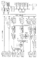
図1、図2は、この発明による電子機器制御装置、電子機器制御方法が適用された制御装置本体部2と送受信部21A〜21Dからなる制御装置を用いて形成したホームネットワークシステムを説明するための図である。図1、図2に示すように、この実施の形態においては、4つの部屋A、B、C、Dのそれぞれには、テレビ受像機とスピーカからなるテレビジョンセット(以下、TVセットという。)4A、4B、4C、4D等が設置されている。
【0022】
以下の説明においては、部屋A、B、C、Dのそれぞれには、TVセット4A、4B、4C、4Dが設置されている場合として説明するが、各部屋には、パーソナルコンピュータや、他のAV機器などの種々の電子機器を設置し、これらをルータ5などを通じて接続することも可能である。
【0023】
部屋Aには、制御装置本体部2と、地上波放送、衛星放送の受信機能を備え、地上波放送番組、衛星放送番組の記録/再生が可能な記録再生装置としてのハードディスク装置(図においては、HDD(Hard Disk Drive)と記載。)3と、ルータ5と、電話回線に接続されたADSL(Asymmetric Digital Subscriber Line)モデム6が設置されている。
【0024】
図1に示すように、制御装置本体部2、ハードディスク装置3、ADSLモデム6、各部屋のTVセット4A、4B、4C、4Dのそれぞれは、部屋Aに設置されるルータ5を通じて接続されている。制御装置本体部2、ハードディスク装置3、ADSLモデム6、各部屋のTVセット4A、4B、4C、4Dのそれぞれには、装置IDが付与されており、各装置間で相手先を指定したデータの送受信や全体を指定したデータの送受信ができるようにされている。
【0025】
そして、この実施の形態においては、制御部本体装置2が、ルータ5を通じてハードディスク装置3や各部屋のTVセット4A、4B、4C、4Dなどを制御し、ハードディスク装置3からのコンテンツを目的とするTVセットに供給するなどのことができるようにしている。
【0026】
さらに、制御装置本体部2には、後述もするように各部屋および玄関部分外側に設置される送受信部21A、21B、21C、21D、21Eが接続されている。これら送受信部21A、21B、21C、21D、21Eのそれぞれは、電子鍵カード(ICカード)1に記憶されている当該電子鍵カードの所有者の個人識別情報(以下、個人IDという。)などを読み出したり、電子鍵カード1に種々の情報を書き込んだりするためのものである。
【0027】
電子鍵カード1は、後述もするが、このホームネットワークシステムが構築された家庭の家族のそれぞれごとに与えられ、いわゆるカード鍵として用いられるとともに、各部屋の入退室の登録にも用いられるものであり、個人IDなどが記録されたものである。したがって、電子鍵カードは、家族のそれぞれごとに異なるものが存在する。しかし、以下においては、説明を簡単にするため、各人が所有する電子鍵カードを電子鍵カード1として説明する。
【0028】
そして、この実施の形態においては、図2に示すように、送受信部21Aは、制御装置本体部2が設置されている部屋Aの出入口付近に設けられ、また、送受信部21B、21C、21Dのそれぞれは、図2に示すように、部屋B、C、Dの出入口付近に設けられている。また、送受信部21Eは、玄関の外側部分に設けられている。
【0029】
これら送受信部21A〜21Eのそれぞれと、電子鍵カード1とは、電磁誘導や電波を用いた非接触の通信により、データのやり取りを行うことができるようにしている。
【0030】
そして、この実施の形態のホームネットワークシステムにおいては、電子鍵カード1と、送受信部21A〜21Eとを通じて、電子鍵カード1の所有者個人毎の入室、退室を制御装置本体部2に登録するようにして、例えば、部屋Aで視聴していた放送番組を部屋Bに移動しても番組内容が途切れることなく視聴できるようにする、いわゆる部屋を変えてのタイムシフト視聴を実現するなど、視聴対象のコンテンツ(映像情報や音声情報)が、使用者の移動に追従するようにしている。
【0031】
[システムを構成する各電子機器の構成について]
次に、この実施の形態のホームネットワークシステムを構成する電子鍵カード1、制御装置部本体2、送受信部21A〜21E、ハードディスク装置3、TVセット4、TVセットのリモコン41のそれぞれの構成例について説明する。
【0032】
[電子鍵カード1の構成例について]
まず、電子鍵カード1について説明する。図3は、この実施の形態で用いられる電子鍵カード1の構成例を説明するための図である。図3(A)は、電子鍵カード1の表面を示し、電子鍵カード1の表面には、所有者の氏名と、ID番号が表示されている。また、図3(B)は、電子鍵カード1の内部構成例を示しており、この電子鍵カード1内には、後述する送受信部21A〜21Eのリード/ライト部と通信を行うための電磁誘導用のアンテナ101と、制御用IC102とが内蔵されている。
【0033】
制御用IC102内には、CPU(Central Processing Unit)やメモリを含み、所有者の氏名、個人IDの他、所有者のその他の必要な個人情報が記憶されている。この個人情報は、父親、母親、子供などの区別が可能なように構成されている。
【0034】
また、制御用IC102内のメモリに、各所有者が行った送受信部21A〜21Eとの通信の時刻や履歴や、各所有者の外出、帰宅の履歴などを書き込むようにされている。なお、これらの履歴情報は、制御装置本体部2の所定のメモリなどにも記憶されるものである。
【0035】
[制御装置本体部2の構成例について]
次に、制御装置本体部2の構成例について説明する。図4は、この実施の形態の制御装置本体部2の構成例を説明するためのブロック図である。図4に示すように、この実施の形態の制御装置本体部2は、CPUバス211を通じて、CPU201、ROM(Read Only Memory)202、RAM(Random Access Memory)203、EEPROM(Electrically Erasable and Programmable ROM)204、時計回路205、LCD(Liquid Crystal Display)コントローラ206、キーインターフェイス(以下、キーI/Fと略称する。)208、LANインターフェイス(以下、単にLANI/Fという。)210が接続されて構成されたものである。
【0036】
ここで、ROM202は、この実施の形態の制御装置本体部2において実行する種々のプログラム、処理に必要になる種々のデータ等が記録されたものであり、RAM203は、主に各種作業の途中結果などを一時記憶する作業領域として用いられるものである。また、EEPROM204は、電源が落とされても記憶情報が消滅してしまうことのないいわゆる不揮発性メモリであり、後述もするように、使用者個人情報、在室管理情報などの管理情報の他、各種のパラメータなどの情報も記録されるものである。
【0037】
LANI/F210は、図4に示したように、送受信部21A〜21Eからのデータを制御装置本体部2が扱える形式のデータに変換するとともに、逆に、制御装置本体部2からのデータを送受信部21A〜21Eのそれぞれが扱える形式のデータに変換するようにするものである。
【0038】
なお、各送受信部21A〜21Eは、後述もするように、それぞれがCPUなどからなる制御部を備え、自機に割り当てられた装置IDを有しており、各送受信部21A〜21Eから制御装置本体部2に送信するデータには、自機の装置IDを付加することにより、送受信部21A〜21Eの内のどの送受信部から送信されて来たデータかを制御装置本体部2が判別することができるようにされている。
【0039】
また、逆に、制御装置本体部2から、特定の送受信部に制御信号や種々のデータを送信する場合には、送信データには、目的とする送受信部の装置IDを送信先情報として付加して送信することにより、目的とする送受信部に対してのみデータを送信することができる。もちろん、制御装置本体部2から送受信部21A〜21Eのそれぞれに対して、いわゆるブロードキャストで同時に共通の送信データを送信することもできるようにされている。
【0040】
また、図4に示すように、LCDコントローラ206には、LCD207が接続され、LCDコントローラ206の制御に応じて、LCD207には、ガイダンスメッセージや警告メッセージなどの種々の情報が表示するようにされる。また、キーI/F208には、キー操作部209が接続される。キー操作部209は、数字キーファンクションキーなどの複数の操作キーを備えるものであり、このキー操作部209とキーI/F208を通じて、制御装置本体部2は、使用者(ユーザ)からの種々の指示入力を受け付けることができるようにされている。
【0041】
さらに、制御装置本体部2は、通信インターフェイス(以下、通信I/Fと略称する。)212を通じて、ルータ5に接続され、このルータ5を通じて、ハードディスク装置3、TVセット4A〜4D、ADSLモデム6などの電子機器の内の目的とする電子機器に対して制御信号を送信して、その電子機器を制御したり、また、ルータ5を通じて、各電子機器からの情報を受信して、それを処理したりすることもできるようにされている。
【0042】
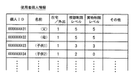
そして、上述もしたように、この実施の形態の制御装置本体部2のEEPROM204には、使用者個人情報と在室管理情報とが記録するようにされている。図5は、使用者個人情報を説明するための図である。使用者個人情報は、この実施の形態のホームネットワークが形成された家庭の構成メンバー毎の個人情報を記録するようにしたものであり、いわゆる使用者個人マスターに相当するものである。
【0043】
この実施の形態においては、使用者個人情報は、個人ID、視聴制限レベル、買物制限レベルなどの予め決められて設定される情報と、在宅/外出フラグなどの現時点の状況に応じて更新される情報とからなるものである。ここで、個人IDは、上述もしたように、家族を構成する各構成メンバーの個々の識別が可能なように、各構成メンバー毎に異なるようにされたものである。
【0044】
なお、図5に示した例の場合、個人IDは、例えば10桁の数字からなり、最初の8桁が家族に共通の家族共通IDと、次の2桁が個人ごとに固有の個人用IDとからなるものである。もちろん、同じ家族を構成する構成メンバー同士であっても、全く異なる数桁の数字、アルファベット、記号などの各種の文字を用いて、独自に設定することも可能である。
【0045】
また、視聴制限レベルは、視聴可能な放送番組を制限するための情報であり、この実施の形態においては、例えば、制限なしのレベル5から幼児向け番組のみのレベル0までの6段階のいずれかに設定することができるようにされる。また、買物制限レベルは、インターネットを通じて買物を行う場合の買物可能金額を制限するものであり、この実施の形態においては、例えば、制限なしのレベル5から買物不可のレベル0までの6段階のいずれかに設定することができるようにされる。
【0046】
その他、年齢、暗証番号など、家族を構成する構成メンバーのそれぞれについての種々の情報についても、使用者個人情報に予め登録することができるようにされる。
【0047】
また、在宅/外出フラグは、家族の構成メンバーが在宅か外出かを把握しておくためのフラグ情報である。在宅/外出フラグは、玄関の外側部分に設けられた送受信部21Eに、各使用者の電子鍵カード1をかざすことにより、送受信部21Eにより読み出された個人IDが制御装置本体部2に送信され、これに基づいて更新される。
【0048】
また、EEPROM204には、在室管理情報も形成される。図6は、在室管理情報を説明するための図である。在室管理情報は、在宅者が現在どの部屋にいるのかを管理する情報である。この実施の形態においては、部屋A、B、C、Dの4つがある場合の例であり、各部屋に入室する場合に送受信部21A〜21Dに電子鍵カード1をかざすことにより、在室の更新がされ、また、各部屋から退出する場合に送受信部に電子鍵カード1をかざすことにより、退室の更新がされる。
【0049】
なお、入室か退室かは、送受信部21A〜21Dを通じて電子鍵カード1から読み取った情報と、図6に示した在室管理情報とのマッチチングを行うことにより、無ければ入室であり、あれば退出であると判断することが可能である。
【0050】
また、図6に示した例の場合には、家族内の各個人を特定することが可能な個人IDの下2桁の数字を用い、各人がどの部屋にいるかを管理している。この図6に示した例の場合、部屋Aには、個人IDがXXXXXXXX01の人(父)と個人IDがXXXXXXXX04の人(子供2)とが在室していることが示されている。また、部屋Cには、個人ID=XXXXXXXX03の人(子供1)が、また、部屋Dには、個人ID=XXXXXXXX02の人(母)が在室していることが示されている。
【0051】
なお、在宅はしているものの、各部屋の送受信部21A〜21Dに電子鍵カード1をかざしていない場合には、例えば、その他の欄に個人IDが書き込まれ、どの部屋にも在室していないとされている家族がいることも把握するようにされる。これは、使用者個人情報の在宅/外出フラグが在宅の状態になっている個人の個人IDと、在宅管理情報の個人IDとのマッチングをかけることによっても検出することができる。
【0052】
また、制御装置本体部2は、現在の各部屋の電子機器の動作状態についても把握し、管理することができるものである。例えば、制御装置本体部2は、ルータ5を通じて各部屋に設置されたTVセット4Aから4Dやハードディスク装置3との間で通信を行うことにより、各電子機器の状態を知り、これを管理することができるものである。
【0053】
そして、詳しくは、後述もするように、制御装置本体部2は、各家族それぞれの入室、退室を検知し、ハードディスク装置3、TVセット4A〜4Dの状態に応じて、ハードディスク装置3と目的とするTVセットとをルータを通じて制御することにより、通常の同一機器においてのタイムシフト視聴の他、TVセットを変えてのタイムシフト視聴をもできるようにしている。
【0054】
[送受信部21A〜21Eの構成例について]
次に、電子鍵カード1からの情報を読み取ることにより、家族の外出と帰宅、各部屋への入室と退室とを検知できるようにするための送受信部21A〜21Eの構成例について説明する。
【0055】
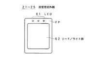
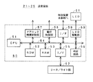
図7は、送受信部21A〜21Dの外観を説明するための図であり、図8は、送受信部21A〜21Dの構成を説明するためのブロック図である。図7に示すように、フロントパネル面FPに、データの読み取り状態などを使用者に通知するための複数個のLED(Light Emitting Diode)が設けられたLED部61と、リード/ライト部62とが設けられたものである。
【0056】
送受信部21A〜21Eのフロントパネル面FPは、電子鍵カード1と同様に長方形状とされるが、その大きさは電子鍵カード1よりも若干大ききなるようにされ、電子鍵カード1との間の通信を信頼性高く行うことができるようにしている。
【0057】
送受信部21A〜21Eのそれぞれは、図8に示すように、CPU51、ROM52、RAM53が、CPUバス54を通じて接続されてマイクロコンピュータの構成とされた制御部50を備え、この制御部50に対して、時計回路56、ドアロック機構駆動部57、電灯制御部58、LED駆動部60が接続されている。
【0058】
ここで、ROM52は、送受信部21A〜21Eの制御部50において実行されるプログラムや処理に必要なデータ、各送受信部21A〜21Eのそれぞれに固有の装置IDなどが記憶されたものである。また、RAM53は、主に作業の途中結果などを一時記憶しておくための作業領域として用いられるものである。なお、ROM52やRAM53の他に、EEPROMなどの不揮発性メモリを設け、これに各送受信部21A〜21Eに固有の装置IDや設定変更可能なパラメータなどを記憶させるようにしてもよい。
【0059】
さらに、制御部50に対しては、I/F55を通じてリード/ライト部62が接続されている。リード/ライト部62は、電磁誘導の作用により、これにかざされた電子鍵カード1に記憶されているデータを読み出して、制御部50に供給したり、また、制御部50からのデータを電子鍵カード1に書き込んだりすることができるものである。
【0060】
また、制御部50は、I/F59を通じて、制御装置本体部2との間でデータの送受を行うことができるとともに、LED駆動部60を制御することにより、LED61の点等、消灯、点滅などを複数のLEDごとに制御することができるようにしている。
【0061】
なお、この実施の形態において、ロック機構駆動部57は、玄関部分の屋外に設置された送受信部21Eにのみ設けられており、後述もするように、認証が確認された場合に、自動的にロック機構を解除することができるようにしている。
【0062】
もちろん、屋内の各部屋の出入口部分にロック機構を設け、屋内の各部屋の出入口部分の送受信部21A〜21Dにもロック機構駆動部57を設けるとともに、屋内の各部屋の出入口部分の外側にもロック機構駆動部57を備えた送受信部を設けることにより、各部屋の入退室時において入退出の制限を行うようにすることもできる。
【0063】
そして、玄関先の送受信部21Eのリード/ライト部62に、電子鍵カード1がかざされると、リード/ライト部62は、電子鍵カード1に記録されている個人IDなどのデータを読み出し、I/F55を通じて制御部50に供給するとともに、時計回路56から取得され制御部50から供給される現在日付情報や現在時刻情報を履歴として電子鍵カード1のメモリの決められた記憶領域に書き込む。
【0064】
そして、制御部50は、I/F58を通じて、自機の装置IDとリード/ライト部62からの個人IDデータとを制御装置本体部2に供給する。これに対応し、制御装置本体部2は、送受信部21Eからのデータに基づいて、送受信部21Eのリード/ライト部62にかざされた電子鍵カード1の所有者は、制御装置本体部2に予め登録された正当な所有者か否かを判断し、その判断結果を、送信先を送受信部21Eとして送信してくるので、これを送受信部21Eは、I/F59を通じて取り込む。
【0065】
送受信部21Eの制御部50は、リード/ライト部62に電子鍵カード1をかざした人が正当な所有者であるとの判別結果を制御装置本体部2から得た場合には、ドアロック機構駆動部57を制御し、ドアロックを解除して、当該所有者の屋内への立ち入りを許可するようにする。
【0066】
また、この場合、制御部50は、RAM53に予め設定された電灯点灯設定時間と時計回路57の現在時刻とを比較し、現在時刻が電灯点灯設定時間内であるときには、電灯制御部58を制御し、少なくとも、立ち入りが許可された玄関部分の電灯を自動点灯させる。なお、電灯を点灯させた場合、一定時間経過後に自動消灯させるようにしたり、使用者の電灯スイッチの操作を待って消灯させるようにしたりすることができる。
【0067】
また、制御部50は、電子鍵カード1からデータが読み出せた場合、あるいは、読み出せなかった場合をLED駆動部60を制御して、LED61の点灯、消灯、点滅などにより通知したり、また、制御装置本体部2からの正当な所有者か否かの判別結果などをLED駆動部60を制御して、LED61の点灯、消灯、点滅により通知したりすることもできるようにされている。
【0068】
なお、制御装置本体部2においては、送受信部21Eからの個人IDに基づいて、誰が帰宅したかを把握し、図5に示した使用者個人情報の在宅/外出フラグを更新して、家族それぞれの在宅/外出を管理することができるようにしている。
【0069】
一方、玄関部分の送受信部21E以外の送受信部21A〜21Dのそれぞれは、自己のリード/ライト部62に電子鍵カード1がかざされると、前述もしたように、電磁誘導の作用により、かざされた電子鍵カード1から個人IDなどの必要な情報を読み出し、これに自機の装置IDを付加してI/F59を通じて制御装置本体部2に送信することができるものである。
【0070】
これにより、制御装置本体部2においては、誰がどの部屋に入室したか、あるいは、退室したかを検出することができ、これが図6を用いて説明した在室管理情報に更新されて、管理することができるようにされる。
【0071】
また、この場合にも、制御部50は、制御装置本体部2のEEPROM204に形成されている在室管理情報に基づいて、同じ部屋に入室者が存在しない場合であって、RAM53に予め設定された電灯点灯設定時刻と時計回路57の現在時刻とを比較し、現在時刻が電灯点灯設定時刻以降であり、かつ、入室した部屋の電灯が点灯されていない場合に、電灯制御部58を制御して、入室した部屋の電灯を点灯させるようにする。
【0072】
また、退室時において、制御部50は、制御装置本体部2のEEPROM204に形成されている在室管理情報に基づいて、同じ部屋に入室者が存在しない場合であって、予め設定され、RAM53に記憶された電灯点灯設定時刻と時計回路57の現在時刻とを比較し、現在時刻が電灯点灯設定時刻以降であり、かつ、入室した部屋の電灯が点灯されている場合に、電灯制御部58を制御して、退室する部屋の電灯を消灯させるようにすることもできる。もちろん、使用者の電灯スイッチの操作を待って電灯の点灯、消灯をさせることも可能である。
【0073】
このように、送受信部21A〜21Eのそれぞれは、リード/ライト部62にかざされた電子鍵カード1の記録データを読み出して、制御装置本体部2に送信し、制御装置本体部2において、上述もしたように、誰が帰宅し、誰がどの部屋にいるかを正確に管理することができるようにしている。
【0074】
なお、外出したか否かは、例えば、玄関内部にも送受信部を設け、外出時に玄関内部に設けられた送受信部に自己の電子鍵カード1をかざすことにより、外出登録を行うようにしたり、また、外出時にも、玄関外部に設けられる送受信部21Eに電子鍵カード1をかざすことにより、外出登録を行うようにしたりすることができる。
【0075】
そして、後者の場合には、例えば、内部からドアのロックが手動で外された場合には、外出時と判断し、送受信部21Eにかざされた電子鍵カード1からの個人IDを外出登録に用いるようにし、ロック解除などの帰宅時の帰宅登録には用いないようにすることにより、外出登録を行うことができる。また、この場合には、ロック機構は自動ロックとしたり、あるいは、電子鍵カード1の個人IDを用いた認証の都度、ロック解除とロック施錠とを切り換えるようにしたりしてもよい。
【0076】
以下に説明する実施の形態においては、後者の場合の例であり、すなわち、玄関外部に設けられた送受信部21Eを外出登録と帰宅登録とで兼用する場合であって、ドアロックは、認証後にドアロックを解除するが、施錠は自動ロックである場合として説明する。
【0077】
[ハードディスク装置3の構成例について]
次に、図1に示したように、TVセット4や、ルータ5を通じて各部屋のTVセット4B〜4Dにコンテンツの提供が可能なハードディスク装置3の構成例について説明する。
【0078】
図9は、この実施の形態のハードディスク装置3の構成例を説明するためのブロック図である。図9において、CPU340は、ホストバスを介し、ROM341、RAM342、EEPROM343を必要に応じアクセスし、このハードディスク装置3の全体の制御を行う。
【0079】
また、図9に示すように、ホストバスには、赤外線のリモコン信号の受光部344が接続されている。受光部344は、リモコン31からの赤外線のリモコン信号を受光し、これを電気信号に変換して、CPU340に供給することができるようにされている。これにより、CPU340は、リモコン31を通じて供給されるユーザからの指示に応じた処理を行うように各部を制御したり、種々の設定を例えばEEPROM343に対して行ったりすることができるようにされている。
【0080】
なお、ROM341は、この実施の形態のハードディスク装置3において実行する各種のプログラムや処理に必要となる各種のデータが記録されたものであり、RAM342は、処理の途中結果を一時記録するなど、主に作業領域として用いられるものである。また、EEPROM343は、いわゆる不揮発性メモリであり、電源が落とされても保持しておく必要のあるデータ、例えば、各種の設定データなどを記憶保持しておくためのものである。
【0081】
そして、図9に示すこの実施の形態のハードディスク装置3は、デジタル入力端部として、デジタルBS/CSチューナー301と、デジタル入力/出力端子302とを備え、また、アナログ入力端部として、地上波チューナー304と、アナログオーディオ入力端子305およびアナログビデオ入力端子306とを備えている。
【0082】
また、デジタル出力端部として、デジタル入力/出力端子302が用いられるようにされ、アナログ出力端部として、アナログオーディオ出力端子322およびアナログビデオ出力端子327を備えている。さらに、通信用接続端子330を備え、例えば、インターネットなどの通信ネットワークを通じて各種のデータの送受を行うことができるようにされている。
【0083】
そして、この図9に示すハードディスク装置3は、上述したデジタル入力端部を通じて受け付けたデジタルビデオ信号やデジタルオーディオ信号を、ハードディスク318に記録したり、デジタル出力端部を通じて出力したり、また、アナログ信号に変換して出力したりすることができるものである。
【0084】
さらに、この図9に示すハードディスク装置3は、上述したアナログ入力端部を通じて受け付けたアナログオーディオ信号やアナログビデオ信号を、アナログ出力端部を通じて出力したり、デジタル信号に変換して、ハードディスク318に記録したり、デジタル出力端部を通じて出力したりすることができるものである。
【0085】
また、上述した通信接続端子330を通じて受け付けたデータをハードディスク318に記録したり、デジタル出力したり、また、受け付けたデータが、ビデオデータやオーディオデータである場合には、これらをアナログ信号に変換して、アナログ出力端部を通じて出力することもできるようにされている。
【0086】
[デジタル入力の利用について]
上述した各入力端部を通じて情報の供給を受ける場合のこの実施の形態のハードディスク装置3の動作について説明する。まず、デジタルBS/CSチューナー301を通じて、BSデジタル放送信号、CSデジタル放送信号を受信し、これをハードディスク318に記録したり、アナログ出力したりする場合の動作について説明する。
【0087】
デジタルBS/CSチューナー301には、図示しないが、衛星からのデジタル放送信号を受信するためのパラボナアンテナが接続されている。そして、デジタルBS/CSチューナー301は、CPU340から供給されるユーザからの選局指示に応じた選局制御信号に基づいて、目的とするデジタル放送信号を受信、選局し、この受信、選局したデジタル放送信号を多重/分離回路316に供給する。
【0088】
デジタル放送信号は、番組伝送路としてのチャンネル毎に、PSI(Program Specific Information)と呼ばれる選局情報や電子番組案内表を形成するためのEPG(Electronic Program Guide)データなどの種々の制御データと共に、放送番組を構成する画像データ(ビデオデータ)や音声データ(オーディオデータ)、その他の種々のデータがパケット化され、多重化されて送信されるものであり、いわゆるTS(Transport Stream)信号の形式とされたものである。
【0089】
各パケットのそれぞれには、識別子(ID)が付加されており、この識別子によって、PSIデータやEPGデータを抽出したり、同じ番組を構成する画像パケットや音声パケットを抽出したりすることができるようにされている。
【0090】
多重/分離回路316は、デジタルBS/CSチューナー301からのTS信号からPSIやEPGデータを抽出し、これをCPU340に供給して、番組の選択を可能にすると共に、電子番組案内表を形成して、これをユーザからの指示に応じて表示するように出力し、電子番組案内表を通じての番組選択や録画予約などを可能にする。
【0091】
また、多重/分離回路316は、選択された番組の記録が指示されている場合には、デジタルBS/CSチューナー301からのTS信号からユーザにより選択された目的とする番組のビデオパケットとオーディオパケットとを抽出して、これらと必要な制御データとからなる新たなTS信号を形成し、これをバッファ制御回路317を通じてハードディスク318に記録するようにする。
【0092】
同時に、多重/分離回路部316は、デジタルBS/CSチューナー301からのTS信号から抽出された目的とする番組のビデオパケットからビデオES(Elementary Stream)を形成し、これをMPEG(Moving Picture Experts Group)ビデオデコーダ323に供給し、また、オーディオパケットからオーディオES(Elementary Stream)を形成して、これをMPEGオーディオデコーダ319に供給する。
【0093】
MPEGオーディオデコーダ319は、これに供給されたオーディオESを復号化処理し、ベースバンドのオーディオデータを得て、これをポスト音声信号処理回路320に供給する。MPEGビデオデコーダ323は、これに供給されたビデオESを復号化処理して、ベースバンドのビデオデータを得て、これをポスト映像信号処理回路324に供給する。
【0094】
ポスト映像信号処理回路324は、MPEGビデオデコーダ323からのビデオデータと、後述するプリ映像信号処理回路314からのビデオデータとの切り換えや、画面合成やフィルタ処理などを行い、処理後のビデオデータをOSD(On Screen Display)回路325に供給する。
【0095】
OSD回路325は、画面表示用のグラフィックッスや文字データの生成を行い、OSD回路324に供給されたビデオデータに対して、生成したグラフィックスや文字データを重ねたり、部分的に表示させるようにしたりする等の処理を施し、処理後のビデオデータをNTSCエンコーダ325に供給する。
【0096】
NTSCエンコーダ325は、これに入力されたビデオデータ(コンポーネントデジタル信号)をYC信号に変換した後、D/A変換を行い、アナログのコンポジットビデオ信号Cとセパレートビデオ信号Sを生成して、そのそれぞれをアナログビデオ信号の出力端子327を通じて出力するようにする。
【0097】
一方、ポスト音声信号処理回路320では、MPEGオーディオデコーダ319からのオーディオデータと、プリ音声信号処理回路309からのオーディオデータとの切り換えや、フィルタ処理、フェード処理、話速変換処理等を行い、処理後のオーディオデータを音声D/A変換器321に供給する。音声D/A変換器321は、これに供給されたオーディオデータをアナログオーディオ信号に変換し、これをアナログオーディオ信号の出力端子322を通じて出力する。
【0098】
なお、アナログオーディオ出力端子322、アナログビデオ出力端子327の後段には、例えば、TVセット4Aが接続され、アナログオーディオ出力端子322を通じて出力されたアナログオーディオ信号に応じた音声がTVセット4Aのスピーカから放音するようにされ、アナログビデオ出力端子327を通じて出力されたアナログビデオ信号に応じた画像がTVセット4Aの表示画面に表示するようにされる。
【0099】
このように、この実施の形態のハードディスク装置においては、デジタルBS/CSチューナー301を通じて受信、選局したデジタル放送信号から目的とする番組のビデオデータとオーディオデータとを抽出し、これをハードディスク318に記録すると共に、同時にアナログビデオ信号とアナログオーディオ信号とを形成して、これを出力することができるようにされる。つまり、デジタル放送信号として提供される目的とする番組をハードディスク318に記録しながら、その番組を視聴することができるようにされている。
【0100】
また、上述したように、多重/分離回路316において新たに形成するようにしたTS信号をデジタルインターフェイス回路303、デジタル入出力端子302、および、ルータ5を通じて、他の部屋のTVセット4A〜4Dや他の記録装置やパーソナルコンピュータなどの外部機器に対して供給することもできるようにされている。この場合、デジタルインターフェイス回路303においては、これに供給されたデジタル信号を外部の機器に適合する形式のデジタル信号に変換し、これを出力する。
【0101】
また、この逆に、例えば、外部機器などからIEEE1394のようなデジタルインターフェイスを介して供給されるデジタル信号をデジタル入力/出力端子302を通じて受け付け、これを記録媒体318に記録したり、アナログビデオ信号、アナログオーディオ信号を形成して、出力したりすることもできるようにされている。
【0102】
すなわち、デジタル入力/出力端子302を通じて供給を受けたデジタル信号は、デジタルインターフェイス回路303に供給される。デジタルインターフェイス回路303は、これに供給されたデジタル信号について、この実施の形態の画像処理装置が用いている方式に適合するようにフォーマット変換等の処理を施し、TS信号を生成して、これを多重/分離回路316に供給する。
【0103】
多重/分離回路316では、更に制御信号等の解析や生成を行い、ハードディスク318に記録する形式のTS信号を形成し、これを前述もしたように、バッファ制御回路317を通じてハードディスク318に記録することができるようにしている。
【0104】
また、多重/分離回路316は、デジタルインターフェイス回路303から供給されたTS信号からビデオES、オーディオESを形成し、MPEGビデオデコーダ323、MPEGオーディオデコーダ319に供給することにより、上述もしたようにアナログビデオ信号、アナログオーディオ信号を形成し、これらを出力することもできるようにされている。
【0105】
[アナログ入力の利用について]
次に、地上波チューナー304、アナログオーディオ入力端子305、アナログビデオ入力端子306を通じて、アナログ信号の入力を受け付け、これをハードディスク318に記録したり、アナログ出力したりする場合の動作について説明する。
【0106】
地上波チューナー304は、地上波のアナログ放送信号を受信、選局して復調し、アナログビデオ信号(コンポジット信号)とアナログオーディオ信号と得て、これらを入力切換回路307に供給する。同様に、外部からのコンポジットビデオ信号Cとオーディオ信号も入力切換回路307に供給される。
【0107】
入力切換回路307は、CPU340からの制御信号に従い、目的とする信号を選択して出力する。すなわち、入力切換回路307は、地上波チューナー304からのアナログビデオ信号とアナログオーディオ信号とを出力するか、アナログオーディオ入力端子305、アナログビデオ入力端子306からのアナログオーディオ信号とアナログビデオ信号とを出力するかを切り換えるものである。
【0108】
入力切換回路307から出力される信号のうち、アナログオーディオ信号はA/D変換器308に供給され、また、アナログビデオ信号(コンポジット信号)はYC分離回路311に供給される。YC分離回路311は、これに供給されたアナログビデオ信号をYC分離、すなわち、輝度信号Yと色差信号Cとに分離し、これらを入力切換回路312に供給する。この入力切換回路312には、外部からのセパレートビデオ信号Sも供給するようにされている。
【0109】
入力切換回路312は、CPU340からの指示に従い、外部からのセパレートビデオ信号SとYC分離回路311からのビデオ信号とのうちの一方を選択し、選択したビデオ信号をNTSC(National Television System Committee)デコーダ回路313に供給する。
【0110】
NTSCデコーダ回路313は、これに入力されたアナログビデオ信号に対して、A/D変換、クロマデコード等の処理を施し、デジタルコンポーネントビデオデータ(ビデオデータ)に変換し、これをプリ映像信号処理回路314に供給する。また、NTSCデコーダ313は、入力されたビデオ信号の水平同期信号を基準に生成したクロックと、同期分離して得た水平同期信号、垂直同期信号、フィールド判別信号を同期制御回路328に供給する。
【0111】
同期制御回路328は、これに供給された各信号を基準とし、各回路ブロックにおいて必要なタイミングを提供するクロック信号、同期信号を生成し、これを各回路ブロックに供給する。
【0112】
また、プリ映像信号処理回路314は、入力されたビデオデータにプリフィルタ等の各種映像信号処理を施し、これをMPEGビデオエンコーダ315とポスト映像信号処理回路324に供給する。
【0113】
MPEGビデオエンコーダ315は、プリ映像信号処理回路314からの画像データにブロックDCT(Discrete Cosine Transform:離散コサイン変換)等の符号化処理を施し、ビデオESを生成し、多重/分離回路316に供給する。
【0114】
一方、入力切換回路307で選択されたオーディオ信号はA/D変換器308にて、デジタルオーディオ信号(オーディオデータ)に変換されたのち、プリ音声信号処理回路309に供給される。プリ音声信号処理回路309は、これに供給されたオーディオデータに対してフィルタ処理を施し、これをMPEGオーディオエンコーダ310に供給する。
【0115】
MPEGオーディオエンコーダ310は、これに供給されたオーディオデータをMPEGフォーマットに従い圧縮した後、オーディオESを生成し、ビデオデータの場合と同様に、多重/分離回路316に供給する。
【0116】
多重/分離回路316は、記録時においては、MPEGビデオエンコーダ315からのビデオESとMPEGオーディオエンコーダ310からのオーディオESと各種制御信号との多重化処理を行う。つまり、記録時における多重/分離回路316は、これに入力されたMPEGビデオESと、MPEGオーディオESとを、各種制御信号と合わせ、多重化処理を施し、例えばMPEGシステムのTS信号を生成する。ここで生成されたTS信号が、バッファ制御回路317を通じて記録媒体318に記録される。
【0117】
また、図1に示すように、プリ音声信号処理回路309からのオーディオデータは、MPEGオーディオエンコーダ310に供給されると共に、ポスト音声信号処理回路320にも供給され、また、プリ映像信号処理回路314からのビデオデータは、MPEGビデオエンコーダ315に供給されると共に、ポスト映像信号処理回路324にも供給するようにされている。
【0118】
そして、ポスト音声信号処理回路320、D/A変換器321の機能により、アナログオーディオ信号を形成し、これを出力すると共に、ポスト映像信号処理回路324、OSD回路325、NTSCエンコーダ326の機能により、アナログビデオ信号を形成し、これを出力することができるようにされている。
【0119】
すなわち、地上波チューナー304、アナログオーディオ入力端子305、アナログビデオ入力端子306を通じて供給されたアナログ信号をデジタル信号に変換してこれを記録媒体318に記録する処理と平行して、この記録対象のビデオデータとオーディオデータとを再生して出力することができるようにされている。
【0120】
もちろん、デジタル信号に変換された地上波チューナー304、アナログオーディオ入力端子305、アナログビデオ入力端子306からの信号を、デジタルインターフェイス303、デジタル入力/出力端子302、および、ルータ5を通じて、他の部屋のTVセットなどに供給することもできるようにされる。
【0121】
[ハードディスク318からの再生について]
次に、上述のようにしてハードディスク318に記録されたビデオ信号とオーディオ信号とを再生する場合のこの実施の形態のハードディスク装置3の動作について説明する。CPU340の制御により、記録媒体318から再生しようとする目的とするTS信号が読み出され、これがバッファ制御回路317を通じて多重/分離回路316に供給される。
【0122】
再生時において、多重/分離回路316は、記録媒体318から読み出されたTS信号から、ビデオES、オーディオESの分離処理を行い、分離したオーディオESをMPEGオーディオデコーダ319に供給し、ビデオESをMPEGビデオデコーダ323に供給する。
【0123】
MPEGオーディオデコーダ319以降の各回路部の処理、および、MPEGビデオデコーダ323以降の各回路部の処理は、デジタル入力を用いる場合において説明した通りである。すなわち、MPEGオーディオデコーダ319に供給されたオーディオESからアナログオーディオ信号が形成されて出力され、MPEGビデオデコーダ323に供給されたビデオESからアナログビデオ信号が形成されて出力される。
【0124】
これにより、アナログオーディオ出力端子322、アナログビデオ出力端子327の後段に接続された例えばTVセット4Aを通じて、ハードディスク318から読み出されたビデオデータ、オーディオデータに応じた画像、音声を出力し、これを視聴することができるようにされる。
【0125】
もちろん、ハードディスク318から読み出されたデジタルビデオ信号、デジタルオーディオ信号をデジタルインターフェイス303、デジタル入力/出力端子302、および、ルータ5を通じて、他の部屋のTVセット4A〜4Dなどにも供給する事もできるようにされている。
【0126】
[通信接続端子、通信インターフェイスの利用について]
また、上述もしたように、この実施の形態のハードディスク装置3は、通信インターフェイス329、通信接続端子330を備え、例えば、電話回線などを経由してインターネットなどのネットワークに接続し、そのネットワークを通じて、各種のデータを取得したり、また、各種のデータをネットワークに送出したりすることができるものである。
【0127】
ここで、送受可能な各種のデータとしては、ビデオデータやオーディオデータの他、各種のプログラムやテキストデータなどの送受も可能である。ビデオデータやオーディオデータの場合には、多重/分離回路316を通じて、記録媒体318に記録することができる。
【0128】
また、多重/分離回路316と、MPEGオーディオデコーダ319、ポスト音声信号処理回路320、D/A変換器321、オーディオ出力端子322からなるオーディオ信号の再生系と、MPEGビデオデコーダ323、ポスト映像信号処理回路324、OSD325、NTSCエンコーダ326、ビデオ出力端子327からなるビデオ信号の再生系を用いることによって、通信ネットワークを通じて取得したビデオデータやオーディオデータを再生し、これらを利用することもできるようにされる。
【0129】
また、通信インターフェイス329、通信接続端子330を通じて取得したビデオデータやオーディオデータをデジタルインターフェイス303、デジタル入力/出力端子302、および、ルータ5を通じて、他の部屋のTVセット4B〜4Dなどにも供給することもできるようにされている。
【0130】
さらに、この実施の形態のハードディスク装置3において用いられるプログラムや制御データなどの提供をネットワークを通じて受けて、これをEEPROM343などに記録保持し、必要に応じてこれを利用するようにするなどのこともできる。
【0131】
例えば、通信ネットワークを通じて、この実施の形態のハードディスク装置3の機能をアップさせるようにしたり、EPGデータなどを事前に得て、予め電子番組案内表を作成したりしておくなどのこができるようにされる。
【0132】
なお、この実施の形態においては、ビデオデータとオーディオデータとは、MPEG方式の圧縮を行うようにしているが、他の圧縮方式を用いることも可能であるし、また、データ圧縮することなく、非圧縮のまま処理することも可能である。
【0133】
また、デジタル入力/出力端子302、デジタルインターフェイス303を通じて、自機宛ての制御信号を受信したときには、これは、デジタルインターフェイス303からCPU340に供給されて用いるようにされる。逆に、この実施の形態のハードディスク装置3のCPU340からの要求などの信号は、デジタルインターフェイス303、デジタル入力/出力端子302を通じて、制御装置本体部2などに送信することもできるようにされる。
【0134】
[タイムシフト視聴について]
そして、この実施の形態のハードディスク装置3は、BSテレビ放送、CSテレビ放送、地上波テレビ放送による放送番組を視聴する場合には、視聴するように選択された放送番組の放送信号を一度ハードディスク318に記録し、そのハードディスク318から目的とする放送番組の放送信号を読み出して再生するというように、常に、ハードディスク318を介してテレビ放送番組を再生するようにすることができるものである。
【0135】
そして、放送番組の視聴中に、トイレに立つなどする場合などにおいて、再生一時停止などの所定の操作を行うことにより、放送番組のハードディスク318への記録は続行し、再生一時停止が解除されるまで、再生が停止される。そして、使用者が戻ってきたときに、再生一時停止を解除するなどの所定の操作を行うことによって、席を離れた時点のシーンから放送番組の視聴を続行するようにすることができるようにしている。
【0136】
さらに、詳しくは後述もするように、制御装置本体部2の制御によりタイムシフト視聴の機能を拡大し、部屋を移動した場合においても、前の部屋で視聴していたテレビ放送番組を前の部屋の続き部分から移動先の部屋において自動的に視聴することもできるようにしている。すなわち、ハードディスク装置3を通じて再生されるコンテンツが、使用者に追従することができるようにしている。
【0137】
[TVセット4の構成例について]
次に、図1、図2に示したように、各部屋に設置されるとともに、ルータ5を通じて、制御装置本体部2、ハードディスク装置3とも接続されるTVセット4A〜4Dの構成例について説明する。
【0138】
なお、TVセット4Aは、ハイビジョン対応の高級機、TVセット4B〜4Dはハイビジョンには対応していない一般機というような違いはあるものの、基本機能は同じであるので、以下においては、TVセット4A〜4Dを、同様の構成を有するTVセット4として説明する。
【0139】
図10は、この実施の形態のTVセット4の構成例を説明するためのブロック図である。図10に示すように、この実施の形態のTVセット4は、CPU421、ROM422、RAM423がCPUバス424を通じて接続されてマイクロコンピュータの構成とされた制御部420を備えている。この制御部420は、このTVセット4の各部を制御するものである。
【0140】
また、CPUバス424には、I/F425を通じてキー操作部426が接続されるとともに、リモコン信号受光部427が接続されている。キー操作部426は、数字キー、チャンネル選択キー、音量調整キーなど、使用者からの指示入力を受け付ける各種の操作キーが設けられたものである。
【0141】
また、リモコン信号受光部427は、キー操作部426と同じ様に各種の操作キーが設けられたリモコン41からの赤外線のリモコン信号を受光し、これを電気信号に変換して制御部420に供給することができるものである。制御部420は、キー操作部426やリモコン信号受光部427を通じて受け付けた使用者からの指示入力に応じて、各部を制御することができるものである。
【0142】
そして、この実施の形態のTVセット4においては、図10にも示すように、3つの入力端部を有し、そのそれぞれを通じて入力される映像信号と音声信号とは、セレクタ404に供給される。
【0143】
すなわち、受信アンテナ401で受信された地上波テレビ放送信号は、UHF/VHFチューナー部402に供給される。UHF/VHFチューナー部402は、これに供給されたテレビ放送信号の中から、制御部420からの選局制御信号に基づいて、目的とするテレビ放送信号を受信選局し、この受信選局したテレビ放送信号を復調して、映像/音声分離部403に供給する。映像/音声分離部403は、これに供給された復調されたテレビ放送信号から映像信号と音声信号とを分離し、これらをセレクタ404に供給する。
【0144】
また、例えば、VTRやDVDプレーヤなどの外部機器からのアナログ映像信号とアナログ音声信号とは、アナログ映像信号の入力端子409とアナログ音声信号の入力端子410とを通じてその供給を受け付ける。このアナログ映像信号の入力端子409とアナログ音声信号の入力端子410とを通じて受け付けたアナログ映像信号、アナログ音声信号もセレクタ404に供給される。
【0145】
また、例えば、ルータ5を通じて送信されてくる映像データと音声データとを含むパケットデータ(デジタルデータ)は、デジタル入力/出力端子411を通じて受け付けられ、受け付けられたデジタルデータは、デジタルインターフェイス412に供給される。デジタルインターフェイス412は、自機宛てのデジタルデータを取り込んで、この実施の形態のTVセット4において処理が可能な形式のデジタルデータに変換し、これをデコーダ413に供給する。
【0146】
デコーダ413は、これに供給されたデジタルデータに施されている符号化処理を復号化し、符号化前のデジタルデータを復元するとともに、映像データと音声データとを分離し、そのそれぞれをD/A(デジタル/アナログ)変換部414に供給する。
【0147】
D/A変換部414は、これに供給されたデジタル信号の映像データと音声データとをアナログ信号に変換し、変換後の映像信号と音声信号とをセレクタ404に供給する。
【0148】
セレクタ404は、使用者からの指示入力に応じた制御部420からの選択制御信号に基づいて、指示された入力端からの映像信号と音声信号とを出力する。つまり、セレクタ404は、UHF/VHFチューナー部402からの映像信号と音声信号とを出力するか、入力端子409、410を通じて供給された映像信号と音声信号とを出力するか、デジタル入力/出力端子411を通じて供給された映像信号と音声信号とを出力するかを切り換える。
【0149】
セレクタ404から出力された映像信号は、映像信号処理部405に供給され、ここでディスプレイ406に供給する形式の映像信号に変換されて、変換後の映像信号がディスプレイ406に供給される。これにより、ディスプレイ406の表示面に、これに供給された映像信号に応じた映像が表示するようにされる。
【0150】
また、セレクタ404から出力された音声信号は、音声信号処理部407に供給され、ここでスピーカ408に供給する音声信号に変換されて、変換後の音声信号がスピーカ408に供給される。これにより、スピーカ408からこれに供給された音声信号に応じた音声が放音するようにされる。
【0151】
また、デジタル入力/出力端子411、デジタルインターフェイス412を通じて、自機宛ての制御信号を受信したときには、これは、デジタルインターフェイス412から制御部420に供給されて用いるようにされる。逆に、この実施の形態のTVセット4の制御部420からの要求などの信号は、デジタルインターフェイス412、デジタル入力/出力端子411を通じて、制御装置本体部2などに送信することもできるようにされる。
【0152】
[帰宅時の処理と放送番組のタイムシフト視聴処理について]
次に、上述したように構成されるこの第1の実施の形態のホームネットワークシステムの動作について図11、図12のフローチャートを参照しながら具体的に説明する。
【0153】
[帰宅時の処理の処理について]
まず、図11を参照しながら、上述したように構成されるこの実施の形態のホームネットワークシステムが構築された家庭に家族が帰宅した場合の主に制御装置本体部2と送受信部21Eとにおいての動作について説明する。
【0154】
制御装置本体部2に接続された送受信部21Eの制御部50は、常時、例えば一定間隔で、電子鍵カード1との間で通信を行ったか否かを監視している(ステップS101)。
【0155】
ステップS101の処理において、電子鍵カード1との間で通信を行ったと判断したときには、送受信部21Eの制御部50は、リード/ライト部62を通じて、これにかざされた電子鍵カード1から個人IDなどの情報を取り込み(ステップS102)、これに自機の装置IDを付加し、I/F59を通じて制御装置本体部2に転送する(ステップS103)。
【0156】
制御装置本体部2においては、ステップS103において送受信部21Eから送信された電子鍵カード1からの個人IDに基づいて、当該電子鍵カード1の所有者が、制御装置本体部2に予め登録された家族であるか否かの認証チェックを行って、その認証チェック結果を送信先を送受信部21Eとして返信してくる。
【0157】
送受信部21Eの制御部50は、上述のように、制御装置本体部2から返信されてくる認証チェック結果をI/F59を通じて受信し(ステップS104)、受信した認証チェック結果が認証されたことを示すものか否か(認証OKか否か)を判断する(ステップS105)。
【0158】
ステップS105の判断処理において、認証されていないと判断したときには、送受信部21EのLED61のうち、赤色のLEDを点滅させ(ステップS106)、ステップS101からの処理を繰り返す。
【0159】
これにより、電子鍵カード1から個人IDが正確に取り込めなかったりするなどして、適正に認証処理が行えなかった場合には、ステップS101からの処理の再試行により正常な処理が可能となる。また、電子鍵カード1がこの実施の形態のホームネットワークシステムで用いられるものではない場合などにおいては、ステップS107以降の処理には進めないことになる。
【0160】
そして、ステップS105の判断処理において、認証がされたと判断したときには、送受信部21Eの制御部50は、送受信部21EのLED61のうち、緑色のLEDを1秒間点灯させ(ステップS107)、認証がされたことを使用者に通知するようにした後、ドアロック機構駆動部57を制御して、玄関ドア部分に設けられたドアロック機構の施錠を解除する(ステップS108)。
【0161】
そして、送受信部21Eの制御部50は、ドアロックが解除された玄関ドアが実際に開かれたか否かを判断する(ステップS109)。この判断処理は、図8には示さなかったが、玄関ドア部分に設けられたドア開閉センサからの出力をI/Fを通じて制御部50が得て、玄関ドアが開かれたか否かを判断することになる。
【0162】
ステップS109の判断処理において、玄関ドアが開かれていないと判断したときには、制御部50は、時計回路56の時刻を監視して、ドアロック解除から10秒経過したか否かを判断する(ステップS110)。
【0163】
ステップS110の判断処理において、ドアロック解除から10秒経過していないと判断したときには、制御部50は、ステップS109からの処理を繰り返す。また、ステップS110の判断処理において、ドアロック解除から10秒経過したと判断したときには、制御部50は、ドアロック機構駆動部57を制御して、ドアロックを施錠し(ステップS111)、ステップS101からの処理を繰り返す。
【0164】
また、ステップS109の判断処理において、玄関ドアが実際に開かれたと判断したときには、送受信部21Eの制御部50は、在宅者登録要求を生成し、これをI/F59を通じて制御装置本体部2に転送する(ステップS112)。
【0165】
この在宅者登録要求を受け付けた制御装置本体部2においては、EEPROM204に形成されている図5に示した使用者個人情報の在宅/外出フラグを在宅を示す状態にする在宅者登録処理が行われることになる。
【0166】
そして、送受信部21Eの制御部50は、ステップS109の判断処理の場合と同様に、玄関ドア部分に設けられたドア開閉センサからの出力をI/Fを通じて得て、ステップS109において開かれたと判断された玄関ドアが、閉じられル間で待ち状態となる(ステップS113)。
【0167】
ステップS113において、玄関ドアが閉じられたと判断したときには、3秒間だけ待った後(ステップS114)、ステップS111の処理に進み、玄関ドアのドアロックを施錠し、ステップS101からの処理を繰り返す。
【0168】
このように、この実施の形態のホームネットワークシステムにおいては、家族のそれぞれが持つ電子鍵カード1を玄関先に設けられた送受信部21Eのリード/ライト部62にかざすだけで、家族の認証がチェックされ、認証が取れた場合にのみ玄関のドアロックが解除されて屋内に入ることができるようにされる。
【0169】
[放送番組のタイムシフト視聴時の処理について]
次に、図12を参照しながら、この実施の形態のホームネットワークシステムにおける放送番組のタイムシフト視聴処理について説明する。まず、具体的な処理の説明に先立って、放送番組のタイムシフト視聴の概要について説明する。
【0170】
上述もしたように、この実施の形態のホームネットワークシステムにおいては、ハードディスク装置3を用いることによって、部屋を変えての放送番組のタイムシフト視聴をできるようにしている。この場合の部屋を変えての放送番組のタイムシフト視聴は、制御装置本体部2のEEPROM204に形成される在室管理情報を利用することにより実現することができる。
【0171】
つまり、図11を用いて上述したように、この実施の形態のホームネットワークシステムが構築された家庭の家族が帰宅すると、送受信部21Eのリード/ライト部62に自己の電子鍵カード1をかざすことにより、認証チェックを受け、認証が取れた場合にドアロックが解除されて屋内への立ち入りが許可され、在宅登録がするようにされる。
【0172】
同様に、この実施の形態のホームネットワークシステムが構築された家庭の屋内において、各部屋に入室する場合、あるいは、入室した部屋から退室する場合においても、各部屋の出入口付近に設けられた送受信部21A〜21Eのリード/ライト部62に自己の電子鍵カードをかざすことにより、個人IDが読み出され、制御装置本体部2に転送されて、入室、退室のタイミングが把握されるとともに、図6に示した在室管理情報が更新され、各部屋の在室者が管理するようにされている。
【0173】
そして、ある部屋でテレビ放送番組を視聴している場合において、その部屋の送受信部のリード/ライト部62に電子鍵カード1がかざされることにより、その電子鍵カード1の所有者の退室が検出された場合に、他に在室者がいない場合には、放送信号のタイムシフト再生のためのハードディスクへの記録は続行するが、ハードディスクからの放送信号の再生は停止させる。
【0174】
その電子鍵カード1の所有者が別の部屋に入室したことが検出された場合に、退室時点において再生されていた放送信号の再生位置からの再生を再開させ、新たに入室した部屋のTVセットを通じて視聴できるようにする。つまり、放送番組が使用者に追従するようにいて再生することができるようにしている。
【0175】
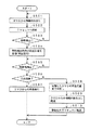
以下、図12のフローチャートに沿って、この実施の形態のホームネットワークシステムにおけるタイムシフト視聴時の処理について説明する。以下においては、部屋Aにおいて放送番組の視聴を開始した場合の例として説明する。
【0176】
上述したように、部屋Aの送受信部21Aのリード/ライト部62に電子鍵カードがかざされ、個人IDが読み出されて、これに送受信部21Aの装置IDが付加されて、I/F59を通じて制御装置本体部2に転送されて在室管理情報が更新される。この後、自動あるいは手動で、ハードディスク3およびTVセット4Aの電源が投入されて、タイムシフト視聴が可能なようにされると、制御装置本体部2とハードディスク装置3とが協働して、図12に示す処理を開始する。
【0177】
すなわち、電源が投入されたハードディスク装置3は、使用者からの選局指示に応じた放送信号の受信を開始し(ステップS201)、受信した放送信号を自己のハードディスク318に記録して行く(ステップS202)。ここでの記録は、放送信号の全部を記録することを目的とするものではなく、視聴者が中座してから戻って来るまでの時間である例えば5分から10分程度の放送信号をいわゆるリングバッファ的に記録して行くものである。
【0178】
そして、ハードディスク318に記録した放送信号を一定時間遅延させるようにした位置から読み出し(ステップS203)、これをデコードするなどの処理を行って、部屋AのTVセット4Aに供給し(ステップS204)、放送番組をその部屋AのTVセット4Aを通じて視聴できるようにする。
【0179】
ここで、記録よりも再生を若干遅延させるようにするのは、使用者が中座するなどして、タイムシフト視聴を行う場合に、当該使用者が視聴できなくなるシーンを生じさせることがないようにするためである。
【0180】
そして、制御装置本体部2は、送受信部21Aから個人IDが送信されてきて、タイムシフト視聴可能な態様で放送番組が視聴されている部屋Aの在室者の移動、すなわち、タイム視聴可能な態様で放送番組が視聴されている部屋Aからの在室者の退室を検出したか否かを判断する(ステップS205)。
【0181】
すなわち、各部屋の送受信部21A〜21Dのそれぞれは、自機の装置IDを付加して、電子鍵カード1から読み出した個人IDを送信してくるので、制御装置本体部2は、どの部屋の送受信部から個人IDが送信されて来たかを判別することができるのである。
【0182】
ステップS205の判断処理において、部屋Aからの在室者の移動を検出していないと判断したときには、制御装置本体部2、ハードディスク装置3は、ステップS202からの処理を繰り返す。ステップS205の判断処理において、部屋Aからの在室者の移動を検出したと判断したときには、制御装置本体部2は、ルータ5を通じて、移動検出時点のハードディスク上の再生位置を取得し、これを記憶する(ステップS206)。また、このステップS206においては、退室者の個別IDが、例えば、在室管理情報のその他の欄に記録するようにされ、退室者が管理するようにされる。
【0183】
ハードディスク装置3は、放送信号を記録するハードディスク318上の記憶エリアを大きき取るようにし、放送信号の記録を続行する(ステップS207)。この場合には、単に部屋を移動する場合もあれば、外出したり、入浴したりするために比較的に長い時間に渡って退室したままとなることをも考慮し、1時間から数時間程度、あるいは、その放送番組が終了するまでの間においては、記録した放送信号をハードディスク318から消去することなく放送信号を記録する。
【0184】
なお、このステップS207においては、退室者が検出された部屋に、他の在室者がいる場合には、記録と再生とを続行するようにし、他に在室者がいない場合には、制御装置本体部2は、ルータ5を通じてハードディスク装置3、TVセット4Aを制御し、再生処理を停止させるとともに、TVセット4Aの電源を自動的にオフにするようにしている。
【0185】
また、その放送番組が終了するまで記録するようにする場合には、その放送信号に付加された付加情報に基づいて、その放送が終了したか否かを判別するようにしたり、予め使用者が、その放送の終了時刻をハードディスク装置3や制御装置本体部2に登録しておくことにより実現することができる。
【0186】
そして、ステップS205で移動が検出された使用者の移動先が検出されたか否か、すなわち、ステップS205で部屋を退室するようにした使用者が、退室した部屋を含め、いずれかの部屋に入室したか否かを判断する(ステップS208)。
【0187】
このステップS208の判断処理においても、各送受信部21A〜21Dから送信されてくるデータには、その送受信部の装置IDが付加されているので、制御装置本体部2は、ステップS205で部屋を退室するようにした使用者が、どの部屋に移動したのかを判別することができるのである。
【0188】
また、このステップS208に判断処理においては、図6に示した在室管理情報のその他の欄に登録された使用者が、いずれかの部屋に入室したか否かに応じて判断することができ、入室した部屋の送受信部21A〜21Dのリード/ライト部62に自己の電子鍵カードをかざすことによって、入室の登録を行うようにすることができる。
【0189】
ステップS208の判断処理において、移動先を検出していないと判断したときには、制御装置本体部2、ハードディスク装置3は、ステップS207からの処理を繰り返す。ステップS208の判断処理おいて、移動先を検出した、すなわち、ステップS205において、退室が検出された使用者のいずれかの部屋への入室が検出されたと判断したときには、制御装置本体部2は、ハードディスク装置3を制御して、ステップS206において記憶したハードディスク318上の再生位置からの放送信号の読み出しを再開し(ステップS209)、読み出した放送信号を移動先のTVセットに転送する(ステップS210)。
【0190】
これにより、部屋Aにおいて視聴していた放送番組を、部屋B、C、Dに移動した後においても、自動的にタイムシフトするようにして再生し、これを視聴することができるようにされる。
【0191】
なお、ステップS209の処理においては、制御装置本体部2が、移動先のTVセットの電源が投入されているか否かをルータ5を通じて確認し、電源が投入されていないときには、その部屋のTVセットの電源を自動的に投入するようにすることもできる。また、制御装置本体部2は、移動元の部屋に在室者がいない場合であって、TVセットの電源が投入されたままであるときには、その移動元の部屋のTVセットの電源を自動的にオフにするようにすることもできる。
【0192】
また、図12において、ステップS210の処理の後に、ステップS205の判断処理と同様に、さらに使用者が移動したか否かを判断し、移動したと判断したときには、ステップS206からの処理を繰り返すようにしてもよい。
【0193】
このように、この実施の形態のホームネットワークシステムにおいては、電子鍵カード1の所有者の各部屋への入室と退室とを管理し、さらにハードディスク装置3やTVセット4A〜4Dの動作状態をも管理して、同じ部屋においてのタイムシフト視聴と部屋を変えてのタイムシフト視聴との両方を実現することができるようにしている。
【0194】
[第2の実施の形態]
上述した第1の実施の形態においては、ハードディスク装置3を用いることにより、いわゆるタイムシフト視聴を可能にする場合を説明した。しかし、タイムシフト視聴だけでなく、DVDプレーヤなどを用いたコンテンツの単なる再生の場合においても、コンテンツの再生を使用者の移動に追従するようにして、移動元の部屋から移動先の部屋へと移すようにすることもできる。
【0195】
図13は、この第2の実施の形態のホームネットワークをシステムを説明するための図である。図13に示す第2の実施の形態のホームネットワークシステムは、ハードディスク装置3に変えて、DVDプレーヤ7を用いるようにしている点を除けば、図1〜図10を用いて説明した第1の実施の形態と同様に構成されるものである。このため、図13において、第1の実施の形態のホームネットワークと同様に構成される部分には、同じ参照符号を付し、その詳細な説明は省略することとする。
【0196】
図13に示すように、この第2の実施の形態のホームネットワークシステムの場合には、部屋Aに設置されるDVDプレーヤ7は、部屋AのTVセット4Aに映像信号や音声信号を提供することができるとともに、ルータ5を通じて、部屋B、C、DのTVセット4B、4C、4Dにもコンテンツデータを提供することができるようにされている。
【0197】
そして、上述もしたように、この第2の実施の形態においては、例えば、部屋Aにおいて、DVDプレーヤ7により再生するようにされるコンテンツをTVセット4Aで視聴している場合に、視聴者が他の部屋に移動した場合に、その移動した部屋において、部屋Aで視聴していたコンテンツの続きを自動的に視聴できるようにすることができるものである。つまり、視聴者に再生コンテンツが追従するようにしたものである。
【0198】
まず、この第2の実施の形態で用いるDVDプレーヤ7の構成例について説明する。図14は、この第2の実施の形態のDVDプレーヤ7の構成例を説明するためのブロック図である。図14に示すように、この第2の実施の形態のDVDプレーヤ7は、CPU721、ROM722、RAM723がCPUバス724を通じて接続されてマイクロコンピュータの構成とされた制御部720を備えている。この制御部720は、DVDプレーヤ7の各部を制御するものである。
【0199】
また、CPUバス724には、I/F725を通じてキー操作部726が接続されるとともに、リモコン信号受光部727が接続されている。キー操作部726は、使用者からの指示入力を受け付ける各種の操作キーが設けられたものである。
【0200】
また、リモコン信号受光部727は、キー操作部726と同じ様に各種の操作キーが設けられたリモコン71からの赤外線のリモコン信号を受光し、これを電気信号に変換して制御部720に供給することができるものである。制御部720は、キー操作部726やリモコン信号受光部727を通じて受け付けた使用者からの指示入力に応じて、各部を制御することができるものである。
【0201】
この第2の実施の形態のDVDプレーヤ7に装填されたDVDは、図示しないが、スレッドモータによって回転駆動される。読み出し部701は、図示しないが、光ピックアップ、2軸アクチュエータ、各種のサーボ回路などを備え、DVDにレーザ光を照射し、その反射光を受光することによって、DVDに記録されたデータを読み出し、これを分離回路702に供給する。
【0202】
分離回路702は、読み出し部701からのデータをそのままデジタルインターフェイス703に供給するとともに、読み出し部701からのデータから映像データと音声データとを分離抽出し、映像データを映像デコーダ705に供給し、音声データは音声デコーダ709に供給する。
【0203】
デジタルインターフェイス703は、これに供給されたデジタルデータを外部に出力する形式のデータに変換し、これをデジタル入力/出力端子704を通じて外部に出力する。
【0204】
また、映像デコーダ705は、これに供給された映像データに施されている符号化処理を復号化し、復号化後の映像データを映像信号処理部706に供給する。映像信号処理部706は、これに供給された映像データに対して所定のフィルタ処理などを行い、処理後の映像データをNTSCエンコーダ707に供給する。
【0205】
NTSCエンコーダ707は、これに入力された映像データ(コンポーネントデジタル信号)をYC信号に変換した後、D/A変換を行い、アナログのコンポジットビデオ信号Cとセパレートビデオ信号Sを生成して、そのそれぞれをべつ別に用意されるアナログビデオ信号の出力端子708を通じて出力する。
【0206】
一方、音声デコーダ709は、これに供給された音声データに施されている符号化処理を復号化し、復号化後の音声データを音声信号処理部710に供給する。音声信号処理部710は、これに供給された音声データに対して、フィルタ処理、フェード処理などの必要な処理を行い、処理後の音声データをD/A変換部711に供給する。D/A変換部711は、これに供給された音声データをアナログ音声信号に変換し、これをアナログオーディオ信号の出力端子712を通じて出力する。
【0207】
このように、この実施の形態のDVDプレーヤ7は、記録媒体であるDVDにデジタルデータとして記録されているコンテンツをデジタルインターフェイス703や、外部に設けられているルータ5などを通じて、各部屋に設けられているTVセット4B〜4Dなどに供給することができるとともに、DVDに記録されている映像データ、音声データを復号化して、アナログ信号に変換し、これを出力して直接にTVセット4Aに供給することもできるものである。
【0208】
なお、ルータ5を通じて、この第2の実施の形態のDVDプレーヤ7にも制御信号などが送信されてくるが、これは、デジタル入力/出力端子704、デジタルインターフェイス703を通じて受け付けて、デジタルインターフェイス703から制御部720に供給され、これを制御部720により利用することができるようにされる。
【0209】
また、制御720からの制御データを、デジタルインターフェイス703、デジタル入力/出力端子704を通じて、例えば制御装置本体部2などの他の電子機器に送信することもできるようにされる。
【0210】
[DVDからのコンテンツの再生処理について]
次に、DVDプレーヤ7を用いたDVDからのコンテンツの再生時の処理について、▲1▼移動検出時にコンテンツの再生一時停止を行う場合(再生一時停止対応モード)、▲2▼移動検出時にコンテンツの再生は停止させずに再生位置を記憶しておき、移動先検出時に早戻しして再生を繰り返すようにする場合(早戻し対応モード)、▲3▼移動検出時にコンテンツの再生は停止させずに再生位置を記憶しておき、移動先に応じて処理を変える場合(移動先対応モード)とに分けて説明する。
【0211】
まず、具体的な処理の説明に先立って、部屋を変えてのDVDプレーヤからのダイレクト再生の概要について説明する。上述もしたように、この第2実施の形態のホームネットワークシステムにおいては、DVDプレーヤ7を用いることによって、部屋を変えての再生コンテンツの継続視聴をできるようにしている。この場合の部屋を変えてのコンテンツの継続視聴は、前述したタイムシフト視聴の場合と同様に、制御装置本体部2のEEPROM204に形成される在室管理情報を利用することにより実現される。
【0212】
そして、第1の実施の形態の場合のホームネットワークシステムの場合と同様に、この第2の実施の形態のホームネットワークシステムが構築された家庭の屋内において、各部屋に入室する場合、あるいは、入室した部屋から退室する場合においても、各部屋の出入口付近に設けられた送受信部21A〜21Dのリード/ライト部62に自己の電子鍵カード1をかざすことにより、個人IDが読み出され、これが読み出した送受信部21A〜21Dの装置IDとともに制御装置本体部2に転送されて、入室、退室のタイミングが把握されるとともに、図6に示した在室管理情報が更新され、各部屋の在室者が管理するようにされている。
【0213】
そして、ある部屋でDVDプレーヤ7により再生するようにしているコンテンツを視聴している場合において、その部屋の送受信部のリード/ライト部62に電子鍵カード1がかざされることにより、その電子鍵カード1の所有者の退室が検出された場合に、上述した▲1▼〜▲3▼のいずれかの対応モードで、電子鍵カード1の所有者の移動に対応するようにしているが、いずれの場合においても、再生コンテンツが電子鍵カードの所有者に追従するようにしている。
【0214】
以下、上述の▲1▼〜▲3▼の各モード時の処理について説明するが、いずれの場合においても、ハードディスク装置3に変えてDVDプレーヤ7を用いるようにして図2に示したように構成されるホームネットワークシステムの場合であって、部屋Aにおいて、DVDプレーヤからの再生コンテンツの視聴を開始した場合を例にして説明することとする。
【0215】
[▲1▼再生一時停止対応モード時の処理について]
まず、▲1▼再生一時停止対応モード時の処理について、図15のフローチャートに沿って説明する。上述したように、入室した部屋の送受信部21Aのリード/ライト部62に電子鍵カード1がかざされ、個人IDが読み出されて、これが送受信部21Aの装置IDとともに、I/F59を通じて制御装置本体部2に転送されて在室管理情報が更新するようにされる。この後、自動または手動で、DVDプレーヤ7およびTVセット4Aの電源が投入されて、コンテンツの利用ができる状態にされると、制御装置本体部2とDVDプレーヤ7とは、協働して図15に示す処理を開始する。
【0216】
すなわち、電源が投入されたDVDプレーヤ7は、使用者からの選択指示に応じて、読み出し部702を制御して、自機に装填されたDVDからデータを読み出し(ステップS301)、この読み出したデータを上述したアナログ信号系の各回路を用いてアナログ信号に変換し、これをDVDプレーヤ7の近傍のTVセット4Aに供給して、TVセット7を通じてDVDコンテンツの視聴を可能にする(ステップS302)。
【0217】
そして、制御装置本体部2は、部屋Aの送受信部21Aから送受信部21Aの装置IDとともに個人IDが送信されてきて、DVDコンテンツが視聴されている部屋Aの在室者の移動、すなわち、部屋Aからの在室者の退室を検出したか否かを判断する(ステップS303)。
【0218】
ステップS303の判断処理において、部屋Aの在室者の移動を検出していないと判断したときには、制御装置本体部2、DVDプレーヤ7は、ステップS301からの処理を繰り返す。
【0219】
ステップS303の判断処理において、部屋Aの在室者の移動を検出したと判断したときには、制御装置本体部2は、ルータ5を通じて、DVDプレーヤ7を制御し、DVDの再生を一時停止させる(ステップS304)。このステップS304においては、退室者の個別IDが、例えば、在室管理情報のその他の欄に記録するようにされ、退室者が管理するようにされる。
【0220】
この後、ステップS303で移動が検出された使用者の移動先が検出されたか否か、すなわち、ステップS303で部屋を退室するようにした使用者が、退室した部屋を含め、いずれかの部屋に入室したか否かを判断する(ステップS305)。
【0221】
このステップS305の判断処理は、図6に示した在室管理情報のその他の欄に登録された使用者が、いずれかの部屋に入室したか否かに応じて判断され、入室した部屋の送受信部21A〜21Dのリード/ライト部62に自己の電子鍵カード1をかざすことによって、その電子鍵カード1から個人IDが読み出され、この読み出された個人IDと読み出した送受信部の装置IDとが制御装置本体部2に送信されることにより、これを受信した制御装置本体部2において、入室の登録を行うようにすることができる。
【0222】
ステップS305の判断処理において、移動先を検出していないと判断したときには、このステップS305の処理を繰り返し、目的とする使用者の移動先が検出するようにされる。
【0223】
ステップS305の判断処理おいて、移動先を検出した場合、すなわち、ステップS303において退室が検出された使用者のいずれかの部屋への入室を検出したと判断したときには、制御装置本体部2は、DVDプレーヤ7を制御して、DVDからのコンテンツデータの読み出しを再開し(ステップS306)、読み出したコンテンツデータを移動先のTVセットに転送する(ステップS307)。
【0224】
これにより、部屋Aにおいて視聴していたDVDコンテンツを、部屋B、C、Dに移動した後において、自動的に再生を再開するようにして視聴することができるようにされる。
【0225】
なお、ステップS306の処理においては、例えば移動先のTVセットの電源が投入されているか否かをルータ5を通じて確認し、電源が投入されていないときには、その部屋のTVセットの電源を投入するようにしてもよい。また、移動元の部屋に在室者がいない場合であって、当該部屋のTVセットの電源が投入されている場合には、当該部屋のTVセットの電源をオフにすることもできる。
【0226】
また、図15において、ステップS307の処理の後に、ステップS303の判断処理と同様に、さらに使用者が移動したか否かを判断し、移動したと判断したときには、ステップS304からの処理を繰り返すようにしてももちろんよい。
【0227】
[▲2▼早戻し対応モード時の処理について]
次に、▲2▼早戻し対応モード時の処理について、図16のフローチャートに沿って説明する。上述したように、入室した部屋の送受信部21Aのリード/ライト部62に電子鍵カード1がかざされ、個人IDが読み出されて、これが送受信部21Aの装置IDとともに、I/F59を通じて制御装置本体部2に転送されて在室管理情報が更新するようにされる。この後、自動または手動で、DVDプレーヤ7およびTVセット4Aの電源が投入されて、コンテンツの利用ができる状態にされると、制御装置本体部2とDVDプレーヤ7とは、協働して図16に示す処理を開始する。
【0228】
すなわち、電源が投入されたDVDプレーヤ7は、使用者からの選択指示に応じて、読み出し部702を制御して、自機に装填されたDVDからデータを読み出し(ステップS401)、この読み出したデータを上述したアナログ信号系の各回路を用いてアナログ信号に変換し、これをDVDプレーヤ7の近傍のTVセット4Aに供給して、TVセット7を通じてDVDコンテンツの視聴を可能にする(ステップS402)。
【0229】
そして、制御装置本体部2は、部屋Aの送受信部21Aから、送受信部21Aの装置IDとともに個人IDが送信されてきて、DVDコンテンツが視聴されている部屋Aの在室者の移動、すなわち、部屋Aからの在室者の退室を検出したか否かを判断する(ステップS403)。
【0230】
ステップS403の判断処理において、部屋Aの在室者の移動を検出していないと判断したときには、制御装置本体部2、DVDプレーヤ7は、ステップS401からの処理を繰り返す。
【0231】
ステップS403の判断処理において、部屋Aの在室者の移動を検出したと判断したときには、制御装置本体部2は、ルータ5を通じて、DVDプレーヤ7を制御し、DVDの再生位置を取得してこれを記憶する(ステップS404)。この場合、DVDプレーヤ7の再生は停止させること無く続行させる。このステップS404においては、退室者の個別IDが、例えば、在室管理情報のその他の欄に記録するようにされ、退室者が管理するようにされる。
【0232】
この後、ステップS403で移動が検出された使用者の移動先が検出されたか否か、すなわち、ステップS403で部屋を退室するようにした使用者が、退室した部屋を含め、いずれかの部屋に入室したか否かを判断する(ステップS405)。
【0233】
このステップS405の判断処理は、図6に示した在室管理情報のその他の欄に登録された使用者が、いずれかの部屋に入室したか否かに応じて判断され、入室した部屋の送受信部21A〜21Dのリード/ライト部62に自己の電子鍵カード1をかざすことによって、その電子鍵カード1から個人IDが読み出され、この読み出された個人IDと読み出した送受信部の装置IDとが制御装置本体部2に送信されることにより、これを受信した制御装置本体部2において、入室の登録を行うようにすることができる。
【0234】
ステップS405の判断処理において、移動先を検出していないと判断したときには、このステップS405の処理を繰り返し、目的とする使用者の移動先が検出するようにされる。
【0235】
ステップS405の判断処理おいて、移動先を検出した場合、すなわち、ステップS403において退室が検出された使用者のいずれかの部屋への入室を検出したと判断したときには、制御装置本体部2は、DVDプレーヤ7を制御して、ステップS404において記憶した再生位置までDVDの再生位置を早戻しし(ステップS406)、ステップS404において記憶したDVDの再生位置からコンテンツデータの読み出しを再開し(ステップS407)、読み出したコンテンツデータを移動先のTVセットに転送する(ステップS407)。
【0236】
これにより、部屋Aにおいて視聴していたDVDコンテンツを、部屋B、C、Dに移動した後において、自動的に再生を再開するようにして視聴することができるようにされる。
【0237】
なお、ステップS406の処理においては、例えば移動先のTVセットの電源が投入されているか否かをルータ5を通じて確認し、電源が投入されていないときには、その部屋のTVセットの電源を投入するようにしてもよい。また、移動元の部屋に在室者がいない場合であって、当該部屋のTVセットの電源が投入されている場合には、当該部屋のTVセットの電源をオフにすることもできる。
【0238】
また、図16において、ステップS408の処理の後に、ステップS403の判断処理と同様に、さらに使用者が移動したか否かを判断し、移動したと判断したときには、ステップS404からの処理を繰り返すようにしてももちろんよい。
【0239】
[▲3▼移動先対応モード時の処理について]
次に、▲3▼移動先対応モード時の処理について、図17のフローチャートに沿って説明する。図17において、ステップS501からステップS505までの処理は、図16に示したステップS401からステップS405までの対応する処理と同様の処理である。
【0240】
そして、この図17に示す▲3▼移動先対応モード時の処理においては、ステップS505の判断処理において、ステップS503で移動が検出された使用者の移動先が検出されたと判断した場合には、移動先は元の部屋か否かを判断する(ステップS506)。
【0241】
ステップS506の判断処理において、移動先が元の部屋であると判断したときには、制御装置本体部2、DVDプレーヤ7は、新たな動作を起こすことなく、DVDからの再生を続行する(ステップS507)。
【0242】
この場合には、ステップS503で移動が検出され、ステップS506で元の部屋まで戻ってきたと判断されるまでの間のDVDからの再生コンテンツは視聴できないが、ごく短時間である場合には、早戻しなどの時間を使うことなく、DVDコンテンツの視聴を続行することができる。
【0243】
また、ステップS506の判断処理において、移動先が元の部屋ではないと判断したときには、制御装置本体部2は、DVDプレーヤ7を制御して、ステップS504において記憶した再生位置までDVDの再生位置を早戻しし(ステップS508)、ステップS504において記憶したDVDの再生位置からコンテンツデータの読み出しを再開して(ステップS509)、読み出したコンテンツデータを移動先のTVセットに転送する(ステップS510)。
【0244】
これにより、部屋Aにおいて視聴していたDVDコンテンツを、部屋B、C、Dに移動した後において、視聴できなくなる区間を生じさせること無く自動的に再生を再開するようにして視聴することができるようにされる。
【0245】
なお、ステップS508の処理においては、例えば移動先のTVセットの電源が投入されているか否かをルータ5を通じて確認し、電源が投入されていないときには、その部屋のTVセットの電源を投入するようにしてもよい。また、移動元の部屋に在室者がいない場合であって、当該部屋のTVセットの電源が投入されている場合には、当該部屋のTVセットの電源をオフにすることもできる。
【0246】
また、図17において、ステップS507またはステップS510の処理の後に、ステップS403の判断処理と同様に、さらに使用者が移動したか否かを判断し、移動したと判断したときには、ステップS504からの処理を繰り返すようにしてももちろんよい。
【0247】
このように、この実施の形態のホームネットワークシステムにおいては、電子鍵カード1の所有者の各部屋への入室と退室とを管理し、さらにDVDプレーヤ7やTVセット4A〜4Dの動作状態をも管理して、使用者の移動に再生コンテンツが自動的に追従するようにすることができる。
【0248】
この場合、使用者は、DVDプレーヤ7やTVセット4A〜4Dに対して複雑な操作を行うことなく、電子鍵カード1を各部屋の送受信部のリード/ライト部62にかざすという、ごく簡単な動作だけで、使用者の移動に追従してDVDプレーヤ7からのコンテンツデータの送信先のTVセットを変え、上述のように、DVDコンテンツの続きをその映像、音声を途切れさせること無く視聴できるようにすることができる。
【0249】
なお、第1の実施の形態では、ハードディスク装置3を用いたタイムシフト視聴の場合を、また、第2の実施の形態では、DVDプレーヤを用いた移動先へのデータの転送の場合を例にして説明したが、ハードディスク装置3とDVDプレーヤ7の両方を備えている場合には、コンテンツの再生元に応じて、その両方に対応することができる。
【0250】
また、再生装置としては、DVDプレーヤに限るものではなく、VTR(Video Type Recorder)、レーザディスクプレーヤなどの種々の記録媒体を用いた再生装置、あるいは、記録再生装置を用いた場合に、DVDプレーヤを用いた場合として説明した使用者の移動に応じたデータの転送を行うようにすることができる。
【0251】
なお、上述した場合には、DVDプレーヤ7によるDVDからのコンテンツの再生の場合であっても、少なくとも、上述した▲1▼、▲2▼、▲3▼の各モードを使用者の好みなどに応じて使い分けるようにすることも可能である。
【0252】
[第3の実施の形態]
上述した第1、第2の実施の形態においては、各部屋に設置され、制御装置本体部2に接続される送受信部21A〜21Dを通じて、これにかざされる電子鍵カードから個人IDなどの必要な情報を読み出し、これを制御装置本体部2に供給することにより、使用者の各部屋への入室、退室の検出および登録を行うようにした。しかし、各部屋に送受信部を設けないようにして、ホームネットワークシステムを構築することも可能である。
【0253】
以下に説明するこの第3の実施の形態においては、各部屋に設けられたTVセット4A〜4Dなどの電子機器の遠隔操作装置であるリモートコマンダ(以下、リモコンという。)からのリモコン信号に基づいて、入室、退室の検出および登録を行うようにし、これに基づき、ハードディスク装置を用いたタイムシフト視聴やDVDプレーヤなどの再生装置からの再生データの移動先への転送を実現するようにしたものである。
【0254】
図18は、この第3の実施の形態のホームネットワークシステムの構成例を説明するための図である。この図18示す第3の実施の形態のホームネットワークシステムにおいて、図1から図12を用いて上述した第1の実施の形態のホームネットワークシステムと同様に構成される部分には同じ参照符号を付し、その詳細な説明は省略する。
【0255】
図18に示すように、この第3の実施の形態のホームネットワークシステムは、部屋Aには、制御装置本体部2、ハードディスク装置3、TVセット4A、ルータ5、ADSLモデム6が設けられ、その他の各部屋B、C、Dには、TVセット4B、4C、4Dが設けられている。
【0256】
そして、部屋Aに設けられた制御装置本体部2、ハードディスク装置3、TVセット4A、ADSLモデム6と、その他の部屋B、C、Dに設けられたTVセット4B、4C、4Dとは、ルータ5を通じて相互に接続され、制御データや映像データや音声データなどのコンテンツデータなどを送受することができるようにしている。
【0257】
しかし、図18に示したように、この第3の実施の形態のホームネットワークシステムにおいては、玄関部分の外側に制御装置本体部2に接続された送受信部21Eを備えるものの、各部屋には、制御装置本体部2に接続された送受信部は設けられていない。
【0258】
つまり、帰宅時においては、家族の各人に配布される電子鍵カード1を用いて、認証チェックを受け、認証が取れた場合にドアロックを解除して屋内に入ることが許可するようにされる部分は、前述した第1、第2の実施の形態のホームネットワークシステムと同様である。しかし、各部屋への入室、退室の登録は、例えば各部屋に設置されたTVセット4A、4B、4C、4Dの遠隔操作装置であるリモートコマンダ(以下、リモコンという。)41A、41B、41C、41Dを通じて行うようにしている。
【0259】
[リモコン41の構成例について]
図19、図20は、この第3の実施の形態において各部屋に設置されるTVセット4A、4B、4C、4Dのリモコン41A、41B、41C、41Dを説明するための図である。リモコン41A、41B、41C、41Dのそれぞれは、ほぼ同様に構成されるものであるので、以下においては、リモコン41A、41B、41C、41Dのそれぞれをリモコン41として説明する。
【0260】
図19は、この実施の形態の各部屋に設置されるTVセット4のリモコン41の外観を説明するための図である。図19に示すように、この第3の実施の形態のTVセット4のリモコン41は、そのフロントパネル面に種々の情報を表示するためのLCD4106と、使用者からの指示入力を受け付ける数字キーやファンクションキーなどの複数の操作キーからなる操作キー群4108が設けられている。
【0261】
そして、この第3の実施の形態においては、図19に示すように、各人の電子カードが装填される電子鍵カード用スロットが、リモコン41の右側面に開口部を有するように設けられている。このスロット内部には、これに装填された電子鍵カード1と対向するように、電子鍵カード用リード/ライト部4110が設けられ、スロットに装填された電子鍵カードからのデータの読み出し、当該電子鍵カードへのデータの書き込みを行うことができるようにしている。
【0262】
図18は、リモコン41の構成を説明するためのブロック図である。図20に示すように、リモコン41は、CPU4101、ROM4102、RAM4103がCPUバス4104を通じて接続され、マイクロコンピュータの構成とされた制御部4100を備えている。
【0263】
さらに、CPUバス4104には、LCDコントローラ4105、I/F4107、4109、4111が接続されている。LCDコントローラ4105には、LCD4106が接続されており、制御部4100により制御されるLCDコントローラ4105の制御により、LCD4106に操作状態や各種のガイダンスなどの情報を表示することができるようにしている。
【0264】
また、I/F4107には、キー操作部4108が、I/F4109には、電子鍵カード用リード/ライト部4110が、I/F4111には、リモコン信号送信部4112がそれぞれ接続されている。
【0265】
そして、キー操作部4108を通じて入力された使用者からの操作指示入力は、I/F4107を通じて制御部4100に供給される。制御部4100は、使用者からの指示入力に応じて、インターフェイス4111を通じてリモコン信号送信部4112を制御し、使用者の指示入力に応じた赤外線のリモコン信号をリモコン信号送信部4112から送信することができるようにしている。
【0266】
そして、リモコン41の制御部4100は、上述もしたように、電子鍵カード用リード/ライト部4110を通じて、リモコン41のスロットに装填された電子鍵カード1から個人IDなどの必要な情報を読み出し、これをTVセット4に対して送信するリモコン信号に含めて送信するようにしている。
【0267】
このように、この第3の実施の形態で用いられるTVセット4のリモコン41は、使用者からの指示入力に応じたリモコン信号を形成して送出することができるとともに、送出するリモコン信号には、当該リモコン41に装填された電子鍵カード1から読み出された個人IDなどの情報を含めて送信することができるものである。
【0268】
[リモコン信号を受信するTVセット4の動作について]
そして、上述のように、個人IDなどの情報が含められたリモコン信号を受信するTVセット4は、受信したリモコン信号に応じて自機の各部を制御し、リモコン信号を通じて提供される使用者からの指示に応じて、選局チャンネルの変更や、音量の調整などの種々の動作を行うようにすることができる。
【0269】
さらに、TVセット4の制御部420は、リモコン信号を受信したときには、送信先ID(制御装置本体部2の装置ID)と自機の識別IDと装填された電子鍵カードから読み出した個人IDとキー操作部4108を通じて受け付けた指示内容とからなる通知データを形成し、これをデジタルインターフェイス412とデジタル入力/出力端子411を通じて制御装置本体部2に送信する。
【0270】
TVセット4からの通知データは、ルータ5を通じて制御装置本体部2に供給されることになる。これにより、制御装置本体部2は、どの部屋のTVセットに対して、誰が、どのような操作指示を与えたかを迅速かつ正確に把握することができるようにされる。
【0271】
したがって、リモコン41を通じてTVセット4の電源が投入された場合やチャンネル変更、音量調整などが行われた場合には、リモコン信号に含められた個人IDにより、操作者が特定でき、その操作者が操作するようにしたTVセットが設置されている部屋に在室していることが確認できる。
【0272】
そして、リモコン信号に含められた個人IDを含む通知データがTVセット4から送信されてくる毎に、制御装置本体部2においては、図6を用いて説明した在室管理情報を参照し、在室登録されていない個人IDが送信されて来たときには、在室登録を行うようにする。
【0273】
なお、この第3の実施の形態においては、在室登録を行うときに、他の部屋に既に在室登録されているときには、その先の在室登録を取り消すことにより退室登録をも同時に処理することができ、適正に使用者の在室管理を行うことができるようにされる。
【0274】
[第3の実施の形態における放送番組のタイムシフト視聴について]
そして、この第3の実施の形態のホームネットワークシステムにおいても、図12に示した第1の実施の形態のタイムシフト視聴の場合と同じように、タイムシフト視聴を行うようにすることができる。
【0275】
具体的には、この第3の実施の形態のホームネットワークシステムにおいては、ステップS205において行われる使用者の移動の発生を検出したか否かの判断は、再生一時停止キーなどの予め決められた操作キーが押下されたことを示すリモコン信号を受信したか否かに応じて検出することができる。
【0276】
また、ステップS208において行われる再生一時停止を指示した使用者の移動先を検出したか否かの判断は、再生一時停止が指示された同じ部屋において、当該使用者の個人IDを含む再生一時停止を解除するための所定のキー操作に応じたリモコン信号が送出され、これを示す通知データがその部屋のTVセット4から制御装置本体部2に送信されて来て、これを制御装置本体部2が取り込んだ場合に当該使用者の移動先を検出したと判断することができる。
【0277】
また、再生一時停止が指示された部屋とは異なる部屋において、当該使用者の個人IDを含む、TVセット4の電源投入やチャンネル変更のためのキー操作に応じたリモコン信号が送出され、これを示す通知データがその部屋のTVセット4から制御装置本体部2に送信されて来て、これを制御装置本体部2が取り込んだ場合に当該使用者の移動先を検出したと判断することができる。
【0278】
つまり、ルータ5と、各部屋に設置されるTVセット4A、4B、4C、4Dと、それらに対するリモコン41A、41B、41C、41Dを通じて、リモコン41A、41B、41C、41Dの操作者となる電子鍵カード1の所有者の個人IDを制御装置本体部2に送信することにより、在室管理情報を適正に管理し、使用者の移動の発生と、移動先とを適正に検出して、部屋を変えない場合(元の部屋に戻ってくる場合)と、部屋を変える場合(異なる部屋に移動した場合)との両方において、放送番組のいわゆるタイムシフト視聴を行うようにすることができる。
【0279】
また、図18に示したハードディスク装置3をDVDプレーヤ7に変えることにより、図13〜図17を用いて上述した第2の実施の形態のホームネットワークシステムの場合と同様に、DVDプレーヤ7からの再生データを使用者の移動先に転送するようにすることができる。
【0280】
この場合においても、図15、図16、図17に示したフローチャートのステップS303、ステップS403、ステップS503において行われる使用者の移動の発生を検出したか否かの判断は、再生一時停止キーなどの予め決められた操作キーが押下されたことを示すリモコン信号を受信したか否かに応じて検出することができる。
【0281】
また、図15、図16、図17に示したフローチャートのステップS305、ステップS405、ステップS505において行われる移動した使用者の移動先を検出したか否かの判断は、例えば、再生一時停止が指示された同じ部屋においては、当該使用者の個人IDを含む再生一時停止を解除するための所定のキー操作に応じたリモコン信号が送出され、これを示す通知データ(送信先の装置ID、送信元の装置ID、個人IDからなるデータ)がその部屋のTVセットから制御装置本体部2に送信されて来た場合に当該使用者の移動先を検出することができる。
【0282】
また、再生一時停止が指示された部屋とは異なる部屋においては、当該使用者の個人IDを含む、TVセット4の電源投入やチャンネル変更のためのキー操作に応じたリモコン信号が送出され、これを示す通知データ(送信先の装置ID、送信元の装置ID、個人IDからなるデータ)がその部屋のTVセットから制御装置本体部2に送信されて来た場合に当該使用者の移動先を検出することができる。
【0283】
つまり、ルータ5と、各部屋に設置されるTVセット4A、4B、4C、4Dと、それらに対するリモコン41A、41B、41C、41Dを通じて、リモコン41A、41B、41C、41Dの操作者となる電子鍵カード1の所有者の個人IDとTVセットの装置IDとを制御装置本体部2に送信することにより、在室管理情報を適正に管理し、使用者の移動の発生と、移動先とを適正に検出して、部屋を変えない場合(元の部屋に戻ってくる場合)と、部屋を変える場合(異なる部屋に移動した場合)との両方において、DVDプレーヤ7からの再生データを移動先に転送するようにすることができる。
【0284】
また、ハードディスク装置3とDVDプレーヤ7の両方を備えている場合には、コンテンツの再生元に応じて、その両方に対応し、タイムシフト視聴や再生データの転送を行うようにすることができる。もちろん、ハードディスク装置やDVDプレーヤを用いる場合に限られるものではなく、各種の記録再生装置や再生装置を用いる場合にもこの発明を適用することができる。
【0285】
また、上述の第3の実施の形態においては、各部屋に設置されるTVセット4A、4B、4C、4Dのリモコン41A、41B、41C、41Dを通じて、操作者の個人IDなどの情報を制御装置本体部2に通知するようにしたが、これに限るものではない。ハードディスク装置3、DVDプレーヤ7、制御装置本体部2のリモコンにも電子鍵カードのスロットを設け、個人IDなどの情報を読み出して、これをリモコン信号に含めて送信し、このリモコン信号の受信元の機器から個人IDや操作入力に応じたコマンドを含む通知情報を制御装置本体部2に送信し、タイムシフト視聴や再生データの転送を行うようにしてもよい。
【0286】
また、各部屋で用いられる電子機器のリモコンを用いて、入室や退室の検出および登録を行う場合には、例えば、リモコンに電子鍵カード1が装填されたときには、必ず個人IDを含むリモコン信号の入室登録要求を送出するようにし、また、リモコンから電子鍵カード1が抜き取られたときには、必ず個人IDを含むリモコン信号の退室登録要求を送出するようにして、入室と退室の登録管理を行うようにしてもよい。
【0287】
また、リモコンには電子鍵カードを装填することなく、例えば、家族の各自がリモコンを使う場合に、自分の個人ID等の識別情報をキー操作部を通じて入力し、これをリモコン内のメモリに一時記憶して用いるようにすることもできる。
【0288】
[入室、退室の検出および登録の他の手段]
上述した第1、第2の実施の形態においては、使用者の入室、退室の検出は、送受信部のリード/ライト部が電磁誘導の作用より電子鍵カードから情報を読み出すことによって行うようにし、上述した第3の実施の形態においては、電子機器のリモコンからのリモコン信号に個人IDを含めて送信し、TVセットなどの電子機器を制御装置本体部2に送信することにより行うようにした。しかし、これらに限るものではない。
【0289】
図1、図2に示したような構成のホームネットワークを例にした場合には、例えば、BlueToothなどの近距離無線通信技術を用い、電子鍵カード1と送受信部21A〜21Eとに無線通信部(無線送信部、無線受信部)を搭載する。そして、電子鍵カード1を送受信部21A〜21Eにかざすなどの動作を行うようにしなくても、例えば、部屋に在室している間は、所定のタイミングで電子鍵カード1から個人IDを送信し、入室した部屋の送受信部21A〜21Dとの間で通信を行い、入室、退室の検出を行うようにすることもできる。
【0290】
この場合には、隣接する部屋の送受信部との間で電子鍵カードが通信を行うことが無いように、非常に微弱な電波を用いたり、各部屋からは種々の電波が漏れることが無いようにしたりするなどの方策を講じることにより、使用者は何の動作をも起こすことなく、入室、退室の登録を行って、放送番組のタイムシフト視聴や、再生コンテンツの移動先への転送を行うことができるようにされる。
【0291】
また、この場合には、必ずしも送受信部を各部屋の出入口部分に設ける必要は無く、例えば、各部屋の天井部分など、入室してきた使用者が所持する電子鍵カードとの間で良好に無線通信を行うことが可能な位置に送受信部を設けるようにすればよい。
【0292】
なお、第1、第2の実施の形態においては、制御装置本体部2に接続された送受信部を通じて使用者の移動の発生と移動先の検出を行うようにし、また、第3の実施の形態においては、TVセット4のリモコン41からの個人IDに基づいて、使用者の移動の発生と移動先の検出を行うようにした。
【0293】
このように、必ずいずれか一方を用いるというのではなく、その両方を1つのホームネットワークシステムに取り込み、制御装置本体部2に接続された送受信部を通じても、また、各部屋に設置されるTVセット4などの電子機器のリモコンからのリモコン信号を通じても、使用者の移動の発生と移動先の検出とを行うようにしてもよい。もちろん、上述した近距離無線通信技術を用いた無線通信により、使用者の移動の発生と移動先の検出とを行うようにしてもよい。
【0294】
また、前述した実施の形態においては、テレビ放送番組や映画などのDVDコンテンツなど、映像と音声とが伴うコンテンツを利用する場合を例にして説明したが、利用可能なコンテンツは、必ず映像と音声とが伴うものに限るものではない。映像と音声のいずれか一方だけの利用ももちろん可能である。
【0295】
また、上述した実施の形態においては、各部屋にTVセットを設置する場合を例に説明したが、これに限るものではなく、例えば、パーソナルコンピュータを各部屋に設置し、ルータ5、ADSLモデム6を通じてインターネットに接続し、電子メールの送受信や、各種のコンテンツのダウンロードと実行などを行うようにすることも可能である。
【0296】
また、各部屋にテレビ放送の受信機能を備えたパーソナルコンピュータを設置し、パーソナルコンピュータに搭載されたハードディスク装置を用いて、どの部屋においても、いわゆるタイムシフト視聴をできるようにし、どの部屋において受信選局され再生するようにされている放送信号であっても、上述した発明を用いることによって、どの部屋で視聴していた放送信号であっても、どの部屋に移動しても、タイムシフト視聴できるようにすることが可能である。
【0297】
また、前述した実施の形態においては、タイムシフト視聴を行うようにする場合には、初めから放送信号をハードディスク装置に記録し、記録した放送信号を再生する場合を例にして説明した。しかし、これに限るものではない。例えば、中座するなどために、リモコンのタイムシフトキーを押下操作し、これに応じたリモコン信号を受信した時点から放送信号をハードディスクに記録するようにする。
【0298】
そして、中座した当該使用者が戻ってきて、再度タイムシフトキーを押下操作し、これに応じたリモコン信号を受信したときには、放送信号の記録はそのまま続行するとともに、直前の記録開始時点からハードディスクに記録された放送信号を読み出して再生することによっても、タイムシフト視聴を実現することができる。
【0299】
この場合においても、読み出した放送信号の転送先は、移動先の電子機器とすることにより、部屋を変えてのタイムシフト視聴にも、初めから放送信号を記録することなく対応することが可能である。
【0300】
また、前述の実施の形態においては、玄関部分に設けられた送受信部21Eに電子鍵カードをかざした場合に認証を行い、認証が取れた場合に、ドアロックを解除するとともに、在宅/外出フラグの更新を行うようにした。しかしこれに限るものではない。
【0301】
例えば、玄関部分の送受信部21Eに電子鍵カードをかざした場合に認証を行い、認証が取れた場合には、ドアロックを解除し、この後、いずれかの部屋の送受信部21A〜21Dに電子鍵カードがかざされて個人IDによりその個人が認識された場合に、在宅者有りと判断して、在宅/外出フラグの更新を行うようにしてもよい。すなわち、最低でも2回のチェックを経た後に、在宅者と認識するようにしてもよい。
【0302】
【発明の効果】
以上説明したように、この発明によれば、所定の家屋内において、使用者の在室状況を管理し、使用者の移動の発生と移動先とを正確に検出して、利用しているコンテンツを移動先においても自動的に利用できるようにすることができる。つまり、部屋を変えてのタイムシフト視聴や再生データの転送などの処理を複雑な手間をかけることなくほぼ自動的に行えるようにすることができ、コンテンツの再生情報、例えば映像や音声を使用者の移動に追従するようにすることができる。
【図面の簡単な説明】
【図1】この発明による電子機器制御装置、電子機器制御方法の一実施の形態が適用されたホームネットワークシステムについて説明するための図である。
【図2】図1に示したホームネットワークシステムの実際の構築例を説明するための図である。
【図3】図1、図2に示したホームネットワークシステムにおいて用いられる電子鍵カード(ICカード)1を説明するための図である。
【図4】図1、図2に示したホームネットワークシステムにおいて用いられる制御装置本体部2を説明するための図である。
【図5】図4に示した制御装置本体部2のEEPROMなどに形成され管理される使用者個人情報について説明するための図である。
【図6】図4に示した制御装置本体部2のEEPROMなどに形成され管理される在室管理情報について説明するための図である。
【図7】図1、図2に示したホームネットワークシステムにおいて用いられる制御装置本体部2に接続される送受信部の外観を説明するための図である。
【図8】図1、図2に示したホームネットワークシステムにおいて用いられる制御装置本体部2に接続される送受信部の構成を説明するための図である。
【図9】図1、図2に示したホームネットワークシステムにおいて用いられるハードディスク装置3を説明するための図である。
【図10】図1、図2に示したホームネットワークシステムにおいて用いられるTVセット4を説明するための図である。
【図11】図1、図2に示したホームネットワークシステムにおいて、帰宅時に家族を認証して、ドアロック機構を制御する場合の処理を説明するためのフローチャートである。
【図12】図1、図2に示したホームネットワークシステムにおいて、いわゆるタイムシフト視聴を行うようにする場合の処理を説明するためのフローチャートである。
【図13】この発明による電子機器制御装置、電子機器制御方法の一実施の形態が適用されたホームネットワークシステムの他の例について説明するための図である。
【図14】図13に示したホームネットワークシステムにおいて用いられるDVDプレーヤ7を説明するための図である。
【図15】図13に示したホームネットワークシステムにおいて、再生データの転送を行うようにする場合の処理を説明するためのフローチャートである。
【図16】図13に示したホームネットワークシステムにおいて、再生データの転送を行うようにする場合の処理の他の例を説明するためのフローチャートである。
【図17】図13に示したホームネットワークシステムにおいて、再生データの転送を行うようにする場合の処理の他の例を説明するためのフローチャートである。
【図18】この発明による電子機器制御装置、電子機器制御方法の一実施の形態が適用されたホームネットワークシステムの他の例について説明するための図である。
【図19】図18に示したホームネットワークシステムにおいて用いられるTVセット4のリモコン41の外観を説明するための図である。
【図20】図18に示したホームネットワークシステムにおいて用いられるTVセット4のリモコン41の構成を説明するための図である。
【符号の説明】
1…電子鍵カード(ICカード)、2…制御装置本体部、21A〜21E…送受信部、3…ハードディスク装置、4A、4B、4C、4D…TVセット等、5…ルータ、6…ADSLモデム、7…DVDプレーヤ、41A、41B、41C、41D…リモコン[0001]
TECHNICAL FIELD OF THE INVENTION
The present invention relates to an electronic device control device and an electronic device control method that supervise and control electronic devices installed in each room of a home such as a television receiver, for example.
[0002]
[Prior art]
A plurality of so-called AV (Audio Visual) devices such as a television receiver, a VTR (Video tape Recorder), a DVD (Digital Versatile Disc), a recording / reproducing device, and a recording / reproducing device using a hard disk are used in each home. Is rarely gone.
[0003]
For example, an AV device for a family is installed in a living room, and an AV device for each person is installed in each room, so that a TV broadcast program, a VTR, a DVD, a hard disk or the like can be recorded in any room. More and more homes are equipped with an environment in which content can be reproduced and viewed.
[0004]
In a home having a recording / reproducing apparatus using a hard disk as a recording medium, a process of recording a broadcast program on a hard disk is interposed, such as reading out and reproducing the broadcast program while recording the broadcast program on the hard disk. By doing so, what realizes so-called time-shift viewing is also provided.
[0005]
In the case of this time-shift viewing, when a user is watching a broadcast program and stops in the middle, the recording is continued by performing a predetermined operation, but the reproduction is paused, and when returning, By restarting the reproduction from the broadcast signal that was being reproduced from the recording medium at the time when the intermediate position was stopped, the broadcast program can be viewed without interruption.
[0006]
As described above, many homes have an environment in which content such as a broadcast program or a movie can be reproduced in response to a request of each person using various AV devices in a plurality of rooms and can be viewed.
[0007]
[Problems to be solved by the invention]
By the way, as described above, even when the AV equipment is installed in each room of one home, the AV equipment in each room only functions independently for each room, and is installed in each room. It is difficult and not possible to connect and manage the AV devices organically.
[0008]
For this reason, when performing the above-described time-shift viewing, it is necessary to always return to the source of the AV device that was viewing the broadcast program. If the user moves to and continues, the broadcast program from the living room to his / her own room cannot be viewed. That is, time-shift viewing between AV devices is not realized.
[0009]
In addition, even if the AV equipment is provided in each room, the recording / reproducing device of the hard disk, the DVD player, etc. are not always used in each room, but can be shared by each room. , It is possible to configure the AV system at a lower cost.
[0010]
In view of the above, the present invention provides an electronic device control apparatus and an electronic device control method capable of organically connecting electronic devices such as AV devices and appropriately controlling each of them. The purpose is to:
[0011]
[Means for Solving the Problems]
In order to solve the above-mentioned problems, an electronic device control device according to the invention described in
Communication means for communicating between each of a plurality of electronic devices to be interconnected,
Detecting means for detecting a movement of a user who is using content through the one electronic device at a position corresponding to one of the plurality of electronic devices;
Storage means for storing information indicating a reproduction position of the content used through the one electronic device when the movement of the user is detected by the detection means;
Destination detection means for detecting that the position of the user has moved to a position corresponding to one of the plurality of electronic devices;
When the destination detection unit detects that the user has moved, the content is reproduced from a position corresponding to the information indicating the reproduction position stored in the storage unit, and the destination electronic device An electronic device that reproduces the content through the communication unit so that the electronic device can be used through the communication unit; and a reproduction control unit that controls the destination electronic device.
It is characterized by having.
[0012]
According to the electronic device control device of the present invention, when a user using the content moves through one of the plurality of electronic devices, this is detected by the detecting means. And information indicating the reproduction position of the content used by the storage means.
[0013]
When the destination of the user whose movement has been detected is detected by the destination detection unit, the use of the content from the position indicated by the information indicating the playback position of the content that has been used is determined as the movement of the user. Each electronic device is controlled by the reproduction control unit through the communication unit so that the electronic device can be performed through the electronic device.
[0014]
Thereby, a plurality of electronic devices can be organically linked and controlled, for example, when a user of the content moves, the content in use is transmitted through the electronic device of the destination of the user. The use is allowed to continue. In other words, the content being used is moved following the user, and can be used with any electronic device.
[0015]
An electronic device control device according to a second aspect of the present invention is the electronic device control device according to the first aspect,
The content is a broadcast signal, and in an electronic device that reproduces the content, the content selected and received is recorded on a recording medium, and the content recorded on the recording medium is reproduced in parallel with the recording process. And when the movement of the user is detected by the detection means, the recording of the content on the recording medium is continued without erasing the unreproduced portion of the content. ,
The storage unit stores information indicating a position corresponding to a read position on the recording medium on which the content is recorded at a time when the movement of the user is detected by the detection unit as information indicating the reproduction position. And
The reproduction control means reproduces the content from a position on the recording medium based on the information indicating the reproduction position stored in the storage means.
[0016]
According to the electronic device control apparatus of the second aspect, the content is a broadcast signal, and the content is recorded on a recording medium so that the electronic device for reproducing the content can perform so-called time-shift viewing, and the recording is performed. It is adapted to be read from a medium and reproduced.
[0017]
If the movement of the user using the content is detected by the detection unit, the recording of the broadcast signal as the content is continued to be recorded on the recording medium, and the movement of the user is detected at the time when the movement of the user is detected. The information indicating the position corresponding to the read position of the content from the recording medium is recorded by the recording means as the information indicating the reproduction position.
[0018]
Thereafter, when the destination of the user whose movement has been detected is detected by the destination detection means, the use of the content from the position based on the information indicating the playback position of the content being used is determined as the movement of the user. The above can be performed through the electronic device.
[0019]
As a result, a plurality of electronic devices can be organically linked and controlled, and when using the content, even if the user returns to the position corresponding to the original electronic device while using the content, another electronic device can be controlled. Even when moving to a position corresponding to the device, so-called time-shift viewing of the content is enabled.
[0020]
BEST MODE FOR CARRYING OUT THE INVENTION
Hereinafter, an embodiment of an electronic device control apparatus and an electronic device control method according to the present invention will be described with reference to the drawings.
[0021]
[First Embodiment]
[Overview of Home Network System]
FIGS. 1 and 2 illustrate a home network system formed using a control device including a control device
[0022]
In the following description, a case will be described in which the TV sets 4A, 4B, 4C, and 4D are installed in the rooms A, B, C, and D, respectively. It is also possible to install various electronic devices such as AV devices and connect them through the
[0023]
In the room A, a hard disk device (in the figure, a recording / reproducing device capable of recording / reproducing a terrestrial broadcast program and a satellite broadcast program, having a control device
[0024]
As shown in FIG. 1, the control device
[0025]
In this embodiment, the control unit
[0026]
Further, the control device
[0027]
As will be described later, the electronic
[0028]
In this embodiment, as shown in FIG. 2, the transmission /
[0029]
Each of the transmission /
[0030]
In the home network system according to the present embodiment, entry and exit of each individual owner of the electronic
[0031]
[About the configuration of each electronic device that makes up the system]
Next, the respective configuration examples of the electronic
[0032]
[Example of configuration of electronic key card 1]
First, the electronic
[0033]
The
[0034]
In addition, the time and history of communication with the transmitting / receiving
[0035]
[Regarding Configuration Example of Control Unit Body 2]
Next, a configuration example of the control device
[0036]
Here, the
[0037]
The LAN I /
[0038]
As will be described later, each of the transmission /
[0039]
Conversely, when transmitting a control signal or various data from the control device
[0040]
As shown in FIG. 4, an
[0041]
Further, the control device
[0042]
As described above, the user's personal information and the occupancy management information are recorded in the
[0043]
In this embodiment, the user's personal information is updated according to information set in advance such as a personal ID, a viewing restriction level, a shopping restriction level, and the current status such as a home / out-of-home flag. It consists of information. Here, as described above, the personal ID is different for each member so that each member of the family can be individually identified.
[0044]
In the case of the example shown in FIG. 5, the personal ID is composed of, for example, a 10-digit number. The first 8 digits are a family common ID common to the family, and the next 2 digits are a personal ID unique to each individual. It consists of: Of course, even members constituting the same family can be uniquely set using various characters such as several different numbers, alphabets, and symbols.
[0045]
The parental level is information for restricting a broadcast program that can be viewed. In this embodiment, for example, the parental level is any one of six levels from a
[0046]
In addition, various information about each of the members constituting the family, such as age and personal identification number, can be registered in the user personal information in advance.
[0047]
The at-home / out-of-home flag is flag information for grasping whether the family members are at home or out of the office. The in-home / out-of-home flag is transmitted to the control device
[0048]
In the
[0049]
The entry or exit is determined by matching information read from the electronic
[0050]
In the example shown in FIG. 6, the last two digits of a personal ID capable of specifying each individual in the family are used to manage which room each individual is in. In the case of the example shown in FIG. 6, it is shown that a person (father) having a personal ID of XXXXXXXXX01 and a person (child 2) having a personal ID of XXXXXXXXX04 are present in the room A. In addition, it is shown that a person (child 1) with a personal ID = XXXXXXXX03 is present in room C, and a person (mother) with a personal ID = XXXXXXXX02 is present in room D.
[0051]
When the user is at home, but does not hold the electronic
[0052]
Further, the control device
[0053]
In more detail, as will be described later, the control device
[0054]
[Example of configuration of transmission /
Next, a description will be given of a configuration example of the transmission /
[0055]
FIG. 7 is a diagram for explaining the appearance of the transmission /
[0056]
The front panel surfaces FP of the transmission /
[0057]
As shown in FIG. 8, each of the transmission /
[0058]
Here, the
[0059]
Further, a read / write unit 62 is connected to the
[0060]
In addition, the
[0061]
In this embodiment, the lock
[0062]
Of course, a lock mechanism is provided at the entrance and exit of each indoor room, and the lock
[0063]
When the electronic
[0064]
Then, the
[0065]
When the
[0066]
Further, in this case, the
[0067]
Further, the
[0068]
In addition, the control device
[0069]
On the other hand, each of the transmission /
[0070]
Thus, the control device
[0071]
Also in this case, the
[0072]
Further, at the time of leaving the room, the
[0073]
As described above, each of the transmission /
[0074]
Note that whether or not the user has gone out can be registered, for example, by providing a transmitting / receiving unit inside the entrance and holding the electronic
[0075]
In the latter case, for example, when the door is manually unlocked from the inside, it is determined that the user is going out, and the personal ID from the electronic
[0076]
The embodiment described below is an example of the latter case, that is, a case where the transmission /
[0077]
[Configuration Example of Hard Disk Drive 3]
Next, as shown in FIG. 1, a configuration example of the
[0078]
FIG. 9 is a block diagram for explaining a configuration example of the
[0079]
Further, as shown in FIG. 9, a
[0080]
The ROM 341 stores various programs to be executed in the
[0081]
The
[0082]
Further, a digital input /
[0083]
The
[0084]
Further, the
[0085]
In addition, the data received through the
[0086]
[Use of digital input]
The operation of the
[0087]
Although not shown, a parabolic antenna for receiving a digital broadcast signal from a satellite is connected to the digital BS /
[0088]
The digital broadcast signal includes various control data such as channel selection information called PSI (Program Specific Information) and EPG (Electronic Program Guide) data for forming an electronic program guide table for each channel as a program transmission path. Image data (video data), audio data (audio data), and other various data constituting a broadcast program are packetized, multiplexed, and transmitted. The format of a so-called TS (Transport Stream) signal It was done.
[0089]
An identifier (ID) is added to each packet so that PSI data and EPG data can be extracted, and image packets and audio packets constituting the same program can be extracted by using the identifier. Has been.
[0090]
The multiplexing /
[0091]
When recording of the selected program is instructed, the multiplexing /
[0092]
At the same time, the multiplexing /
[0093]
The
[0094]
The post-video signal processing circuit 324 performs switching between video data from the
[0095]
The
[0096]
The
[0097]
On the other hand, the post audio signal processing circuit 320 performs switching between audio data from the
[0098]
Note that, for example, a TV set 4A is connected to a stage subsequent to the analog
[0099]
As described above, in the hard disk device of this embodiment, video data and audio data of a target program are extracted from the digital broadcast signal received and selected through the digital BS /
[0100]
Further, as described above, the TS signals newly formed in the multiplexing /
[0101]
Conversely, for example, a digital signal supplied from an external device or the like via a digital interface such as IEEE 1394 is received through the digital input /
[0102]
That is, the digital signal supplied through the digital input /
[0103]
The multiplexing /
[0104]
Further, the multiplexing /
[0105]
[Use of analog input]
Next, an operation in a case where an input of an analog signal is received through the
[0106]
The
[0107]
The
[0108]
Among the signals output from the
[0109]
The
[0110]
The NTSC decoder circuit 313 performs processing such as A / D conversion and chroma decoding on the analog video signal input thereto, converts the analog video signal into digital component video data (video data), and converts this into a pre-video signal processing circuit. 314. Further, the NTSC decoder 313 supplies a clock generated based on the horizontal synchronization signal of the input video signal, and a horizontal synchronization signal, a vertical synchronization signal, and a field determination signal obtained by performing synchronization separation to the synchronization control circuit 328.
[0111]
The synchronization control circuit 328 generates a clock signal and a synchronization signal for providing necessary timing in each circuit block based on each signal supplied thereto, and supplies these to each circuit block.
[0112]
Further, the pre-video
[0113]
The
[0114]
On the other hand, the audio signal selected by the
[0115]
The MPEG audio encoder 310 compresses the supplied audio data in accordance with the MPEG format, generates an audio ES, and supplies the audio ES to the multiplexing /
[0116]
The multiplexing /
[0117]
As shown in FIG. 1, the audio data from the pre-audio
[0118]
Then, an analog audio signal is formed by the functions of the post audio signal processing circuit 320 and the D /
[0119]
That is, in parallel with the process of converting an analog signal supplied through the
[0120]
Of course, the digital signals converted from the
[0121]
[Reproduction from Hard Disk 318]
Next, the operation of the
[0122]
At the time of reproduction, the multiplexing /
[0123]
The processing of each circuit unit after the
[0124]
As a result, an image and a sound corresponding to the video data and the audio data read from the
[0125]
Of course, the digital video signal and digital audio signal read from the
[0126]
[Use of communication connection terminal and communication interface]
Further, as described above, the
[0127]
Here, as various types of data that can be transmitted and received, it is possible to transmit and receive various programs and text data in addition to video data and audio data. In the case of video data or audio data, the data can be recorded on the
[0128]
Also, an audio signal reproduction system including a multiplexing /
[0129]
In addition, video data and audio data acquired through the
[0130]
Further, a program or control data used in the
[0131]
For example, it is possible to improve the function of the
[0132]
In this embodiment, the video data and the audio data are compressed according to the MPEG method. However, other compression methods can be used, and without compressing the data, It is also possible to process without compression.
[0133]
When a control signal addressed to the own device is received via the digital input /
[0134]
[About time shift viewing]
When viewing a broadcast program by BS television broadcast, CS television broadcast, or terrestrial television broadcast, the
[0135]
Then, when the user stands in the bathroom while watching the broadcast program, by performing a predetermined operation such as pause, the recording of the broadcast program on the
[0136]
Further, as will be described in detail later, the function of time-shift viewing is expanded under the control of the control device
[0137]
[Configuration Example of TV Set 4]
Next, as shown in FIGS. 1 and 2, a description will be given of a configuration example of the TV sets 4A to 4D that are installed in each room and are also connected to the control device
[0138]
The TV set 4A is a high-definition high-definition device, and the TV sets 4B to 4D are different from a general device that does not support high-definition. However, the basic functions are the same. 4A to 4D will be described as
[0139]
FIG. 10 is a block diagram for explaining a configuration example of the
[0140]
A
[0141]
The remote control signal light receiving unit 427 receives an infrared remote control signal from the
[0142]
The
[0143]
That is, the terrestrial television broadcast signal received by the receiving
[0144]
Further, for example, an analog video signal and an analog audio signal from an external device such as a VTR or a DVD player are supplied via an analog video
[0145]
Also, for example, packet data (digital data) including video data and audio data transmitted through the
[0146]
The decoder 413 decodes the encoding process applied to the supplied digital data, restores the digital data before encoding, separates the video data and the audio data, and converts each of them into a D / A. (Digital / analog) is supplied to the conversion unit 414.
[0147]
The D / A converter 414 converts the supplied video data and audio data of the digital signal into analog signals, and supplies the converted video signal and audio signal to the
[0148]
The
[0149]
The video signal output from the
[0150]
The audio signal output from the
[0151]
When a control signal addressed to the own device is received through the digital input / output terminal 411 and the digital interface 412, the control signal is supplied from the digital interface 412 to the control unit 420 for use. Conversely, a signal such as a request from the control unit 420 of the
[0152]
[Returning to home and time-shift viewing of broadcast programs]
Next, the operation of the home network system according to the first embodiment configured as described above will be specifically described with reference to the flowcharts of FIGS.
[0153]
[About processing at the time of returning home]
First, referring to FIG. 11, when the family returns to the home where the home network system of this embodiment configured as described above is constructed, mainly the control device
[0154]
The
[0155]
In the process of step S101, when it is determined that communication has been performed with the electronic
[0156]
In the control device
[0157]
The
[0158]
When it is determined in the determination processing of step S105 that the authentication has not been performed, the red LED among the LEDs 61 of the transmission /
[0159]
As a result, when the authentication process cannot be properly performed, for example, because the personal ID cannot be accurately taken in from the electronic
[0160]
When it is determined in the determination process of step S105 that the authentication has been performed, the
[0161]
Then, the
[0162]
In the determination process of step S109, when it is determined that the entrance door is not opened, the
[0163]
When it is determined in the determination processing of step S110 that 10 seconds have not elapsed since the door was unlocked, the
[0164]
Also, in the determination processing of step S109, when it is determined that the entrance door has actually been opened, the
[0165]
In the control device
[0166]
Then, the
[0167]
When it is determined in step S113 that the entrance door has been closed, after waiting for three seconds (step S114), the process proceeds to step S111, the door lock of the entrance door is locked, and the processing from step S101 is repeated.
[0168]
As described above, in the home network system of this embodiment, the family authentication is checked only by holding the electronic
[0169]
[About processing when viewing time-shifted broadcast programs]
Next, a time-shift viewing process of a broadcast program in the home network system according to the present embodiment will be described with reference to FIG. First, prior to a description of specific processing, an outline of time-shift viewing of a broadcast program will be described.
[0170]
As described above, in the home network system according to the present embodiment, the
[0171]
That is, as described above with reference to FIG. 11, when the family of the home in which the home network system according to the present embodiment is constructed returns, the user holds his / her own electronic
[0172]
Similarly, when entering or leaving a room in a home where the home network system of this embodiment is constructed, a transmitting / receiving unit provided near the entrance of each room. By holding the user's own electronic key card over the read / write unit 62 of 21A to 21E, the personal ID is read out and transferred to the control device
[0173]
When a television broadcast program is viewed in a certain room, the electronic
[0174]
When it is detected that the owner of the electronic
[0175]
Hereinafter, the processing at the time shift viewing / listening in the home network system of this embodiment will be described with reference to the flowchart of FIG. The following describes an example in which viewing of a broadcast program in room A is started.
[0176]
As described above, the electronic key card is held over the read / write unit 62 of the transmission /
[0177]
That is, the
[0178]
Then, the broadcast signal recorded on the
[0179]
Here, the reason why the reproduction is slightly delayed from the recording is to prevent a situation in which the user cannot view when time-shift viewing is performed, for example, when the user is in the middle. In order to
[0180]
Then, the control device
[0181]
That is, each of the transmission /
[0182]
When it is determined in the determination processing in step S205 that the movement of the occupant from the room A has not been detected, the control device
[0183]
The
[0184]
In this step S207, when there is another occupant in the room where the exited person is detected, recording and reproduction are continued, and when there is no other occupant, control is performed. The device
[0185]
Further, when recording is to be performed until the broadcast program ends, it may be determined whether or not the broadcast has ended based on additional information added to the broadcast signal, or the user This can be realized by registering the end time of the broadcast in the
[0186]
Then, it is determined whether or not the destination of the user whose movement has been detected in step S205 is detected. That is, the user who leaves the room in step S205 enters any one of the rooms including the room that has left. It is determined whether or not it has been performed (step S208).
[0187]
Also in the determination processing in step S208, since the device ID of the transmission / reception unit is added to the data transmitted from each of the transmission /
[0188]
Further, in the determination processing in step S208, it is possible to make a determination according to whether or not the user registered in the other section of the room presence management information shown in FIG. 6 has entered any room. By holding the electronic key card over the read / write unit 62 of the transmission /
[0189]
When it is determined in the determination processing of step S208 that the destination has not been detected, the control device
[0190]
As a result, even after moving to room B, C, or D, the broadcast program watched in room A can be automatically reproduced and time-shifted so that the user can view the broadcast program. .
[0191]
In the process of step S209, the control device
[0192]
In FIG. 12, after the process of step S210, similarly to the determination process of step S205, it is further determined whether or not the user has moved, and when it is determined that the user has moved, the process from step S206 is repeated. It may be.
[0193]
As described above, in the home network system according to this embodiment, the entry and exit of the owner of the electronic
[0194]
[Second embodiment]
In the above-described first embodiment, the case where so-called time-shift viewing is enabled by using the
[0195]
FIG. 13 is a diagram for explaining a system of the home network according to the second embodiment. The home network system according to the second embodiment shown in FIG. 13 uses the
[0196]
As shown in FIG. 13, in the case of the home network system according to the second embodiment, the
[0197]
Then, as described above, in the second embodiment, for example, in the room A, when the content to be reproduced by the
[0198]
First, a configuration example of the
[0199]
Further, a
[0200]
The remote control
[0201]
Although not shown, the DVD loaded in the
[0202]
The
[0203]
The
[0204]
Further, the
[0205]
The
[0206]
On the other hand, the
[0207]
As described above, the
[0208]
A control signal and the like are also transmitted to the
[0209]
Further, the control data from the control 720 can be transmitted to another electronic device such as the control device
[0210]
[Regarding playback of content from DVD]
Next, with respect to the processing at the time of reproducing the content from the DVD using the
[0211]
First, prior to a description of specific processing, an outline of direct reproduction from a DVD player in a different room will be described. As described above, in the home network system of the second embodiment, the
[0212]
Then, as in the case of the home network system in the first embodiment, when entering each room in a house where the home network system of the second embodiment is constructed, Even when the user leaves the room, the personal ID is read out by holding his / her own electronic
[0213]
When the user is viewing content that is to be reproduced by the
[0214]
Hereinafter, the processing in each of the above modes (1) to (3) will be described. In any case, the
[0215]
[1. Regarding processing in playback pause support mode]
First, the processing in the (1) playback pause mode will be described with reference to the flowchart of FIG. As described above, the electronic
[0216]
That is, the powered-on
[0217]
Then, the control device
[0218]
If it is determined in step S303 that the movement of the occupant of the room A has not been detected, the control device
[0219]
When it is determined in the determination process of step S303 that the movement of the occupant of the room A has been detected, the control device
[0220]
Thereafter, it is determined whether or not the destination of the user whose movement has been detected in step S303 has been detected, that is, the user who has left the room in step S303 has moved to any of the rooms, including the room that has left. It is determined whether the user has entered the room (step S305).
[0221]
The determination process in step S305 is performed based on whether the user registered in the other section of the room management information shown in FIG. 6 has entered any of the rooms. The personal ID is read from the electronic
[0222]
If it is determined in step S305 that the destination has not been detected, the process of step S305 is repeated to detect the destination of the intended user.
[0223]
In the determination process of step S305, when the destination is detected, that is, when it is determined that the user who has exited the room in step S303 has been detected to enter any room, the control device
[0224]
As a result, the DVD content viewed in the room A can be viewed by automatically resuming the reproduction after moving to the rooms B, C, and D.
[0225]
In the process of step S306, for example, it is confirmed through the
[0226]
In FIG. 15, after the process of step S307, similarly to the determination process of step S303, it is further determined whether or not the user has moved, and when it is determined that the user has moved, the process from step S304 is repeated. Of course you can.
[0227]
[2] Processing in fast reverse mode
Next, the processing in the (2) fast return mode will be described with reference to the flowchart of FIG. As described above, the electronic
[0228]
That is, the powered-on
[0229]
Then, the control device
[0230]
In the determination processing of step S403, when it is determined that the movement of the occupant of the room A has not been detected, the control device
[0231]
In the determination processing of step S403, when it is determined that the movement of the occupant of the room A has been detected, the control device
[0232]
Thereafter, it is determined whether or not the destination of the user whose movement has been detected in step S403 has been detected, that is, the user who has left the room in step S403 has moved to any of the rooms, including the room that has left. It is determined whether the user has entered the room (step S405).
[0233]
The determination process in step S405 is performed based on whether the user registered in the other section of the room management information shown in FIG. 6 has entered any of the rooms. The personal ID is read from the electronic
[0234]
If it is determined in step S405 that the destination has not been detected, the process of step S405 is repeated to detect the destination of the intended user.
[0235]
In the determination processing of step S405, when the destination is detected, that is, when it is determined that the entry of the user whose exit has been detected in step S403 to any of the rooms has been detected, the control device
[0236]
As a result, the DVD content viewed in the room A can be viewed by automatically resuming the reproduction after moving to the rooms B, C, and D.
[0237]
In the process of step S406, for example, it is confirmed through the
[0238]
In FIG. 16, after the processing in step S408, similarly to the determination processing in step S403, it is further determined whether or not the user has moved, and when it is determined that the user has moved, the processing from step S404 is repeated. Of course you can.
[0239]
[3] Regarding processing in destination correspondence mode
Next, the processing in (3) destination mode will be described with reference to the flowchart of FIG. In FIG. 17, processes from step S501 to step S505 are the same processes as the corresponding processes from step S401 to step S405 shown in FIG.
[0240]
Then, in the processing in the (3) destination corresponding mode shown in FIG. 17, when it is determined in the determination processing in step S505 that the destination of the user whose movement has been detected in step S503 is detected, It is determined whether the destination is the original room (step S506).
[0241]
In the determination processing of step S506, when it is determined that the destination is the original room, the control device
[0242]
In this case, the playback content from the DVD cannot be viewed until the movement is detected in step S503 and it is determined in step S506 that the user has returned to the original room. The viewing of the DVD content can be continued without using time such as return.
[0243]
If it is determined in step S506 that the destination is not the original room, the
[0244]
As a result, after moving to the rooms B, C, and D, the DVD content that was viewed in the room A can be viewed by automatically resuming the reproduction without causing a section where the DVD content cannot be viewed. Is to be.
[0245]
In the process of step S508, for example, it is confirmed whether or not the power of the TV set at the destination is turned on through the
[0246]
In FIG. 17, after the processing in step S507 or S510, similarly to the determination processing in step S403, it is further determined whether or not the user has moved, and when it is determined that the user has moved, the processing from step S504 is performed. May of course be repeated.
[0247]
As described above, in the home network system according to the present embodiment, the entry and exit of the owner of the electronic
[0248]
In this case, the user holds the electronic
[0249]
In the first embodiment, the case of time-shift viewing using the
[0250]
Further, the playback device is not limited to a DVD player, and a playback device using various recording media such as a VTR (Video Type Recorder) and a laser disc player, or a DVD player using a recording / playback device. The transfer of data according to the movement of the user, which has been described as the case of using, can be performed.
[0251]
In the case described above, even when the
[0252]
[Third Embodiment]
In the above-described first and second embodiments, necessary information such as a personal ID and the like is obtained from the electronic key card held over the transmitting / receiving
[0253]
In the third embodiment described below, a remote controller (hereinafter, referred to as a remote controller) is a remote controller for electronic devices such as TV sets 4A to 4D provided in each room. Detection and registration of entry and exit, and based on this, time-shift viewing and listening using a hard disk drive and transfer of playback data from a playback device such as a DVD player to a destination are realized. It is.
[0254]
FIG. 18 is a diagram for explaining a configuration example of the home network system according to the third embodiment. In the home network system according to the third embodiment shown in FIG. 18, the same reference numerals are given to the same components as those of the home network system according to the first embodiment described above with reference to FIGS. However, a detailed description thereof will be omitted.
[0255]
As shown in FIG. 18, in the home network system according to the third embodiment, a room A is provided with a control device
[0256]
The control device
[0257]
However, as shown in FIG. 18, in the home network system according to the third embodiment, although the transmitting and receiving
[0258]
That is, at the time of returning home, the electronic
[0259]
[Example of configuration of remote controller 41]
FIGS. 19 and 20 are diagrams for explaining
[0260]
FIG. 19 is a diagram for explaining the appearance of the
[0261]
In the third embodiment, as shown in FIG. 19, an electronic key card slot into which an individual's electronic card is loaded is provided on the right side of the
[0262]
FIG. 18 is a block diagram for explaining the configuration of
[0263]
Further, an LCD controller 4105, I /
[0264]
Also, a
[0265]
Then, an operation instruction input from the user input through the
[0266]
Then, the control unit 4100 of the
[0267]
As described above, the
[0268]
[Operation of
As described above, the
[0269]
Further, when the control unit 420 of the
[0270]
The notification data from the
[0271]
Therefore, when the power of the
[0272]
Each time notification data including the personal ID included in the remote control signal is transmitted from the
[0273]
In the third embodiment, when performing the room registration, if the room is already registered in another room, the room registration is canceled by canceling the previous room registration, so that the room exit registration is processed at the same time. It is possible to appropriately manage the occupancy of the user.
[0274]
[Time-shift viewing of broadcast programs in the third embodiment]
In the home network system according to the third embodiment, time-shift viewing can be performed in the same manner as in the time-shift viewing of the first embodiment shown in FIG.
[0275]
Specifically, in the home network system according to the third embodiment, whether or not the occurrence of the user's movement performed in step S205 is detected is determined in advance by a reproduction pause key or the like. Detection can be made according to whether or not a remote control signal indicating that the operation key has been pressed has been received.
[0276]
Also, in step S208, it is determined whether or not the movement destination of the user who instructed the reproduction pause is detected, in the same room where the reproduction pause was instructed, the reproduction pause including the user's personal ID is performed. A remote control signal corresponding to a predetermined key operation for canceling is released, and notification data indicating the signal is transmitted from the
[0277]
Further, in a room different from the room where the reproduction pause is instructed, a remote control signal including the personal ID of the user and corresponding to a key operation for turning on the power of the
[0278]
That is, through the
[0279]
Also, by replacing the
[0280]
Also in this case, the determination as to whether or not the occurrence of the user's movement performed in steps S303, S403, and S503 of the flowcharts shown in FIGS. 15, 16, and 17 is made by the reproduction pause key or the like. Can be detected according to whether or not a remote control signal indicating that a predetermined operation key has been pressed is received.
[0281]
The determination as to whether or not the destination of the moved user performed in steps S305, S405, and S505 of the flowcharts shown in FIGS. 15, 16, and 17 is performed, for example, when playback pause is instructed. In the same room, a remote control signal corresponding to a predetermined key operation for releasing the pause of reproduction including the personal ID of the user is transmitted, and notification data indicating the signal (device ID of transmission destination, transmission source Is transmitted from the TV set of the room to the control device
[0282]
In a room different from the room in which the pause of reproduction is instructed, a remote control signal including a personal ID of the user and a key operation for turning on the power of the
[0283]
That is, through the
[0284]
When both the
[0285]
In the third embodiment, information such as the personal ID of the operator is transmitted to the control device through the
[0286]
When detecting and registering entry and exit using a remote controller of an electronic device used in each room, for example, when the electronic
[0287]
In addition, for example, when each family member uses the remote control, without inputting the electronic key card into the remote control, identification information such as his / her personal ID is input through the key operation unit, and this is temporarily stored in a memory in the remote control. It can be stored and used.
[0288]
[Other means for detecting and registering entry and exit]
In the above-described first and second embodiments, the detection of entry and exit of the user is performed by the read / write unit of the transmission / reception unit reading information from the electronic key card by the action of electromagnetic induction. In the third embodiment described above, the remote control signal from the remote controller of the electronic device is transmitted together with the personal ID, and the electronic device such as a TV set is transmitted to the control device
[0289]
In the case of a home network having a configuration as shown in FIGS. 1 and 2, for example, a wireless communication unit is provided between the electronic
[0290]
In this case, a very weak radio wave is used or various radio waves are not leaked from each room so that the electronic key card does not communicate with the transmission / reception unit in the adjacent room. By taking measures such as switching to the other, the user can register to enter and leave the room without taking any action, perform time-shift viewing of the broadcast program, and transfer the playback content to the destination. Be able to be.
[0291]
In this case, it is not always necessary to provide the transmission / reception unit at the entrance / exit of each room. For example, it is possible to satisfactorily communicate wirelessly with an electronic key card possessed by the user who has entered the room, such as the ceiling of each room. The transmitting and receiving unit may be provided at a position where the communication can be performed.
[0292]
In the first and second embodiments, the occurrence of the movement of the user and the detection of the movement destination are performed through the transmission / reception unit connected to the control device
[0293]
As described above, instead of using one of them, both of them are taken into one home network system, and a TV set installed in each room is also provided through a transmission / reception unit connected to the control device
[0294]
Further, in the above-described embodiment, the case where contents accompanied by video and audio, such as DVD content such as a television broadcast program and a movie, is used as an example, but the available content is always video and audio. However, the present invention is not limited to this. It is of course possible to use only one of video and audio.
[0295]
Further, in the above-described embodiment, the case where the TV set is installed in each room has been described as an example. However, the present invention is not limited to this. For example, a personal computer is installed in each room, and the
[0296]
In addition, a personal computer having a function of receiving television broadcasts is installed in each room, and a so-called time-shift viewing can be performed in any room by using a hard disk device mounted on the personal computer. By using the above-described invention, it is possible to perform a time-shifted viewing of a broadcast signal that is broadcast and played back in any room, regardless of whether the broadcast signal has been viewed in any room or moved to any room. It is possible to do so.
[0297]
Further, in the above-described embodiment, a case has been described in which, when performing time-shift viewing, a broadcast signal is recorded on a hard disk device from the beginning and the recorded broadcast signal is reproduced. However, it is not limited to this. For example, a time shift key of the remote controller is pressed down in order to sit down, and the broadcast signal is recorded on the hard disk from the time when the remote control signal corresponding to the key is received.
[0298]
When the user returns to the center and presses the time shift key again to receive a remote control signal corresponding thereto, the recording of the broadcast signal is continued as it is and the recording to the hard disk is started from the immediately preceding recording start time. Time-shift viewing can also be realized by reading and reproducing the recorded broadcast signal.
[0299]
Also in this case, by transferring the read broadcast signal to the destination electronic device, it is possible to cope with time-shift viewing in a different room without recording the broadcast signal from the beginning. is there.
[0300]
In the above-described embodiment, the authentication is performed when the electronic key card is held over the transmitting / receiving
[0301]
For example, authentication is performed when the electronic key card is held over the transmission /
[0302]
【The invention's effect】
As described above, according to the present invention, in a predetermined house, the occupancy of the user is managed, the occurrence and destination of the user's movement are accurately detected, and the content used is determined. Can be automatically used at the destination. In other words, it is possible to perform processing such as time-shift viewing and transfer of playback data in a different room almost automatically without any complicated work, and the playback information of the content, such as video and audio, can be used by the user. Can be followed.
[Brief description of the drawings]
FIG. 1 is a diagram for describing a home network system to which an embodiment of an electronic device control device and an electronic device control method according to the present invention has been applied.
FIG. 2 is a diagram for explaining an example of actual construction of the home network system shown in FIG. 1;
FIG. 3 is a diagram for explaining an electronic key card (IC card) 1 used in the home network system shown in FIGS. 1 and 2.
FIG. 4 is a diagram for explaining a control device
FIG. 5 is a diagram for describing user personal information formed and managed in an EEPROM or the like of the control device
6 is a diagram for explaining occupancy management information formed and managed in an EEPROM or the like of the control device
FIG. 7 is a diagram for explaining an appearance of a transmission / reception unit connected to the control device
FIG. 8 is a diagram for explaining a configuration of a transmission / reception unit connected to the control device
FIG. 9 is a diagram for explaining a
FIG. 10 is a diagram for describing a
FIG. 11 is a flowchart for explaining processing in a case where a family is authenticated when returning home and a door lock mechanism is controlled in the home network system shown in FIGS. 1 and 2;
FIG. 12 is a flowchart for explaining processing in a case where so-called time-shift viewing is performed in the home network system shown in FIGS. 1 and 2;
FIG. 13 is a diagram for explaining another example of a home network system to which an embodiment of an electronic device control device and an electronic device control method according to the present invention has been applied.
14 is a diagram for explaining a
FIG. 15 is a flowchart for explaining a process when transferring reproduction data in the home network system shown in FIG. 13;
FIG. 16 is a flowchart for explaining another example of a process in a case where transfer of reproduction data is performed in the home network system shown in FIG. 13;
FIG. 17 is a flowchart for explaining another example of the processing in the case where the reproduction data is transferred in the home network system shown in FIG. 13;
FIG. 18 is a diagram for explaining another example of a home network system to which an embodiment of an electronic device control device and an electronic device control method according to the present invention has been applied.
FIG. 19 is a diagram for explaining an appearance of a
20 is a diagram for explaining a configuration of a
[Explanation of symbols]
DESCRIPTION OF
Claims (18)
前記複数の電子機器の内の1つの電子機器に対応する位置で当該1つの電子機器を通じてコンテンツを利用している使用者の移動を検知する検知手段と、
前記検知手段により前記使用者の移動が検知された場合に、前記1つの電子機器を通じて利用されている前記コンテンツの再生位置を示す情報を記憶する記憶手段と、
前記使用者の位置が前記複数の電子機器の内の1つの電子機器に対応する位置に移動したことを検知する移動先検知手段と、
前記移動先検知手段により前記使用者が移動したことが検知された場合に、前記記憶手段に記憶されている前記再生位置を示す情報に対応する位置から前記コンテンツを再生し、移動先の電子機器を通じて利用できるように、前記通信手段を通じて、前記コンテンツを再生する電子機器と、前記移動先の電子機器とを制御するようにする再生制御手段と
を備えることを特徴とする電子機器制御装置。Communication means for communicating between each of a plurality of electronic devices to be interconnected,
Detecting means for detecting a movement of a user who is using content through the one electronic device at a position corresponding to one of the plurality of electronic devices;
Storage means for storing information indicating a reproduction position of the content used through the one electronic device when the movement of the user is detected by the detection means;
Destination detection means for detecting that the position of the user has moved to a position corresponding to one of the plurality of electronic devices;
When the destination detection unit detects that the user has moved, the content is reproduced from a position corresponding to the information indicating the reproduction position stored in the storage unit, and the destination electronic device An electronic device control apparatus, comprising: an electronic device that reproduces the content through the communication unit, and a reproduction control unit that controls the destination electronic device so that the electronic device can be used through the communication unit.
前記コンテンツは放送信号であり、前記コンテンツを再生する電子機器においては、受信選局された前記コンテンツを記録媒体に記録するとともに、この記録処理と並行して前記記録媒体に記録した前記コンテンツを再生するようにし、さらに、前記検知手段により前記使用者の移動が検知され場合には、未再生部分の前記コンテンツを消去すること無く、前記コンテンツの前記記録媒体への記録を続行するようにしており、
前記記憶手段は、前記検知手段により前記使用者の移動が検知された時点における前記コンテンツが記録されている前記記録媒体上の読み出し位置に応じた位置を示す情報を前記再生位置を示す情報として記憶し、
前記再生制御手段は、前記記憶手段に記憶された前記再生位置を示す情報に基づく前記記録媒体上の位置から、前記コンテンツの再生を行うようにすることを特徴とする電子機器制御装置。The electronic device control device according to claim 1,
The content is a broadcast signal, and in an electronic device that reproduces the content, the content selected and received is recorded on a recording medium, and the content recorded on the recording medium is reproduced in parallel with the recording process. And when the movement of the user is detected by the detection means, the recording of the content on the recording medium is continued without erasing the unreproduced portion of the content. ,
The storage unit stores information indicating a position corresponding to a read position on the recording medium on which the content is recorded at a time when the movement of the user is detected by the detection unit as information indicating the reproduction position. And
The electronic device control device according to claim 1, wherein the reproduction control unit reproduces the content from a position on the recording medium based on the information indicating the reproduction position stored in the storage unit.
前記検知手段は、前記複数の電子機器の内の前記1つの電子機器を通じて利用している前記コンテンツの再生一時停止が指示された場合に、前記使用者の移動が発生したと検知することを特徴とする電子機器制御装置。The electronic device control device according to claim 1,
The detecting means detects that the movement of the user has occurred when an instruction to pause the reproduction of the content used through the one of the plurality of electronic devices is given. Electronic equipment control device.
前記使用者が持つ前記使用者の識別情報が記録されたメモリ部から情報を読み出す読み出し手段を備え、
前記検知手段は、前記読み出し手段を通じて前記使用者のメモリ部から読み出した前記使用者の前記識別情報に基づいて、前記使用者の移動が発生したか否かを検知することを特徴とする電子機器制御装置。The electronic device control device according to claim 1,
A reading unit that reads information from a memory unit in which the user identification information of the user is recorded,
The electronic device detects whether or not the movement of the user has occurred, based on the identification information of the user read from the memory unit of the user through the reading unit. Control device.
前記使用者が持つ前記使用者の識別情報が記録されたメモリ部から送出される前記識別情報を受信する受信手段を備え、
前記検知手段は、前記受信手段を通じて受信した前記使用者のメモリ部からの前記識別情報に基づいて、前記使用者の移動が発生したか否かを検知することを特徴とする電子機器制御装置。The electronic device control device according to claim 1,
A receiving unit for receiving the identification information sent from the memory unit in which the identification information of the user possessed by the user is recorded,
The electronic device control device according to claim 1, wherein the detecting unit detects whether or not the movement of the user has occurred based on the identification information received from the memory unit of the user through the receiving unit.
前記検知手段は、自機の、あるいは、前記複数の電子機器のいずれかの遠隔操作装置から前記使用者の識別情報が送信されて来た場合に、前記識別情報に基づいて、前記使用者の移動が発生したか否かを検知することを特徴とする電子機器制御装置。The electronic device control device according to claim 1,
The detecting means, the own device, or, when the identification information of the user is transmitted from a remote control device of any of the plurality of electronic devices, based on the identification information, based on the identification information of the user An electronic device control device for detecting whether or not movement has occurred.
前記使用者が持つ前記使用者の識別情報が記録されたメモリ部から情報を読み出す読み出し手段を備え、
前記移動先検知手段は、前記読み出し手段を通じて前記使用者の前記メモリ部から読み出した前記識別情報に基づいて、前記使用者が移動先に移動したか否かを検知することを特徴とする電子機器制御装置。The electronic device control device according to claim 1,
A reading unit that reads information from a memory unit in which the user identification information of the user is recorded,
The electronic device according to claim 1, wherein the destination detection unit detects whether the user has moved to a destination based on the identification information read from the memory unit of the user through the reading unit. Control device.
前記使用者が持つ前記使用者の識別情報が記録されたメモリ部から送出される前記使用者の前記識別情報を受信する受信手段を備え、
前記移動先検知手段は、前記受信手段を通じて受信した前記使用者の前記メモリ部からの前記識別情報に基づいて、前記使用者が移動先に移動したか否かを検知することを特徴とする電子機器制御装置。The electronic device control device according to claim 1,
Receiving means for receiving the identification information of the user transmitted from a memory unit in which the identification information of the user possessed by the user is recorded,
The electronic device according to claim 1, wherein the destination detecting unit detects whether the user has moved to a destination based on the identification information of the user received from the memory unit through the receiving unit. Equipment control device.
前記移動先検知手段は、自機の、あるいは、前記複数の電子機器のいずれかの遠隔操作装置から前記使用者の識別情報が送信されて来た場合に、前記識別情報に基づいて、前記使用者が移動先に移動したか否かを検知することを特徴とする電子機器制御装置。The electronic device control device according to claim 1,
The destination detection unit, based on the identification information, when the identification information of the user is transmitted from the remote control device of the own device or any of the plurality of electronic devices, based on the identification information, An electronic device control device for detecting whether a person has moved to a destination.
前記電子機器制御装置においては、
前記複数の電子機器の内の1つの電子機器に対応する位置で当該1つの電子機器を通じてコンテンツを利用している使用者の移動を検知する検知工程と、
前記検知工程において、記使用者の移動を検知した場合に、前記1つの電子機器を通じて利用されている前記コンテンツの再生位置を示す情報を記憶する記憶工程と、
前記使用者の位置が前記複数の電子機器の内の1つの電子機器に対応する位置に移動したことを検知する移動先検知工程と、
前記移動先検知工程において、前記使用者が移動したことを検知した場合に、前記記憶工程において記憶した前記再生位置を示す情報に対応する位置から前記コンテンツを再生し、移動先の電子機器を通じて利用できるように、前記通信手段を通じて、前記コンテンツを再生する電子機器と、前記移動先の電子機器とを制御する再生制御工程と
を有することを特徴とする電子機器制御方法。An electronic device control method for controlling the plurality of electronic devices through an electronic device control device capable of performing communication with each of the plurality of electronic devices to be connected to each other,
In the electronic device control device,
A detection step of detecting a movement of a user who is using content through the one electronic device at a position corresponding to one of the plurality of electronic devices;
A storage step of storing information indicating a reproduction position of the content used through the one electronic device when the movement of the user is detected in the detection step;
A destination detection step of detecting that the position of the user has moved to a position corresponding to one of the plurality of electronic devices,
In the destination detection step, when detecting that the user has moved, the content is reproduced from a position corresponding to the information indicating the reproduction position stored in the storage step, and is used through the destination electronic device. A method of controlling an electronic device, comprising: an electronic device that reproduces the content through the communication unit; and a reproduction control step that controls the electronic device at the destination.
前記コンテンツは放送信号であり、前記コンテンツを再生する電子機器においては、受信選局された前記コンテンツを記録媒体に記録するとともに、この記録処理と並行して前記記録媒体に記録した前記コンテンツを再生するようにし、さらに、前記検知工程において前記使用者の移動を検知した場合には、未再生部分のコンテンツを消去すること無く、前記コンテンツの前記記録媒体への記録を続行するようにしており、
前記記憶工程においては、前記検知工程において前記使用者の移動を検知した時点における前記コンテンツが記録されている前記記録媒体上の読み出し位置に応じた位置を示す情報を前記再生位置を示す情報として記憶し、
前記再生制御工程においては、前記記憶工程において記憶した前記再生位置を示す情報に基づく前記記録媒体上の位置から、前記コンテンツの再生を行うようにすることを特徴とする電子機器制御方法。The electronic device control method according to claim 10, wherein
The content is a broadcast signal, and in an electronic device that reproduces the content, the content selected and received is recorded on a recording medium, and the content recorded on the recording medium is reproduced in parallel with the recording process. And further, when the movement of the user is detected in the detection step, without erasing the content of the unplayed portion, the recording of the content on the recording medium is continued,
In the storage step, information indicating a position corresponding to a read position on the recording medium where the content is recorded at the time when the movement of the user is detected in the detection step is stored as information indicating the reproduction position. And
The electronic device control method according to claim 1, wherein, in the reproduction control step, the content is reproduced from a position on the recording medium based on the information indicating the reproduction position stored in the storage step.
前記検知工程においては、前記複数の電子機器の内の前記1つの電子機器を通じて利用している前記コンテンツの再生一時停止が指示された場合に、前記使用者の移動が発生したことを検知することを特徴とする電子機器制御方法。The electronic device control method according to claim 10, wherein
In the detecting step, detecting that the movement of the user has occurred when the reproduction pause of the content used through the one of the plurality of electronic devices is instructed. An electronic device control method comprising:
前記電子機器制御装置においては、
前記使用者が持つ前記使用者の識別情報が記録されたメモリ部から情報を読み出す読み出し工程を有し、
前記検知工程においては、前記読み出し工程において前記使用者のメモリ部から読み出した前記使用者の前記識別情報に基づいて、前記使用者の移動が発生したか否かを検知することを特徴とする電子機器制御方法。The electronic device control method according to claim 10, wherein
In the electronic device control device,
A reading step of reading information from a memory unit in which the user identification information of the user is recorded,
In the detecting step, it is detected whether or not the movement of the user has occurred based on the identification information of the user read from the memory unit of the user in the reading step. Equipment control method.
前記電子機器制御装置においては、
前記使用者が持つ前記使用者の識別情報が記録されたメモリ部から送出される前記識別情報を受信する受信工程を有し、
前記検知工程においては、前記受信工程において受信した前記使用者のメモリ部からの前記識別情報に基づいて、前記使用者の移動が発生したか否かを検知することを特徴とする電子機器制御方法。The electronic device control method according to claim 10, wherein
In the electronic device control device,
A receiving step of receiving the identification information sent from the memory unit in which the identification information of the user having the user is recorded,
The electronic device control method according to claim 1, wherein, in the detecting step, whether or not the movement of the user has occurred is detected based on the identification information received from the memory unit of the user in the receiving step. .
前記検知工程においては、自機の、あるいは、前記複数の電子機器のいずれかの遠隔操作装置から前記使用者の識別情報が送信されて来た場合に、前記識別情報に基づいて、前記使用者の移動が発生したか否かを検知することを特徴とする電子機器制御方法。The electronic device control method according to claim 10, wherein
In the detecting step, when identification information of the user is transmitted from the remote control device of the own device or any one of the plurality of electronic devices, the user is identified based on the identification information. A method for controlling an electronic device, comprising: detecting whether or not movement has occurred.
前記使用者が持つ前記使用者の識別情報が記録されたメモリ部から情報を読み出す読み出し工程を有し、
前記移動先検知工程においては、前記読み出し工程において前記使用者の前記メモリ部から読み出した前記識別情報に基づいて、前記使用者が移動先に移動したか否かを検知することを特徴とする電子機器制御方法。The electronic device control method according to claim 10, wherein
A reading step of reading information from a memory unit in which the user identification information of the user is recorded,
In the moving destination detecting step, the electronic device detects whether or not the user has moved to a moving destination based on the identification information read from the memory unit of the user in the reading step. Equipment control method.
前記使用者が持つ前記使用者の識別情報が記録されたメモリ部から送出される前記使用者の前記識別情報を受信する受信工程を有し、
前記移動先検知工程においては、前記受信工程において受信した前記使用者の前記メモリ部からの前記識別情報に基づいて、前記使用者が移動先に移動したか否かを検知することを特徴とする電子機器制御方法。The electronic device control method according to claim 10, wherein
A receiving step of receiving the identification information of the user sent from the memory unit in which the identification information of the user having the user is recorded,
In the destination detecting step, it is detected whether or not the user has moved to a destination based on the identification information of the user received from the memory unit in the receiving step. Electronic device control method.
前記移動先検知工程においては、自機の、あるいは、前記複数の電子機器のいずれかの遠隔操作装置から前記使用者の識別情報が送信されて来た場合に、前記識別情報に基づいて、前記使用者が移動先に移動したか否かを検知することを特徴とする電子機器制御方法。The electronic device control method according to claim 10, wherein
In the destination detection step, the own device, or, when the identification information of the user is transmitted from a remote control device of any of the plurality of electronic devices, based on the identification information, An electronic device control method, comprising: detecting whether a user has moved to a destination.
Priority Applications (6)
| Application Number | Priority Date | Filing Date | Title |
|---|---|---|---|
| JP2002237900A JP2004080382A (en) | 2002-08-19 | 2002-08-19 | Apparatus and method for controlling electronic apparatus |
| US10/642,979 US7613922B2 (en) | 2002-08-19 | 2003-08-18 | Electronic device controlling apparatus, electronic device controlling system, and electronic device controlling method |
| US10/643,190 US6972680B2 (en) | 2002-08-19 | 2003-08-18 | Electronic device controlling apparatus and electronic device controlling method |
| KR1020030056787A KR101014031B1 (en) | 2002-08-19 | 2003-08-18 | Electronics device controlling apparatus, electronics device controlling system and electronics device controlling method |
| KR1020030057286A KR20040016801A (en) | 2002-08-19 | 2003-08-19 | Electronic device controlling apparatus and electronic device controlling method |
| US11/109,025 US7482922B2 (en) | 2002-08-19 | 2005-04-18 | Electronic device controlling apparatus and electronic device controlling method |
Applications Claiming Priority (1)
| Application Number | Priority Date | Filing Date | Title |
|---|---|---|---|
| JP2002237900A JP2004080382A (en) | 2002-08-19 | 2002-08-19 | Apparatus and method for controlling electronic apparatus |
Publications (2)
| Publication Number | Publication Date |
|---|---|
| JP2004080382A true JP2004080382A (en) | 2004-03-11 |
| JP2004080382A5 JP2004080382A5 (en) | 2005-04-07 |
Family
ID=32021473
Family Applications (1)
| Application Number | Title | Priority Date | Filing Date |
|---|---|---|---|
| JP2002237900A Pending JP2004080382A (en) | 2002-08-19 | 2002-08-19 | Apparatus and method for controlling electronic apparatus |
Country Status (3)
| Country | Link |
|---|---|
| US (2) | US6972680B2 (en) |
| JP (1) | JP2004080382A (en) |
| KR (1) | KR20040016801A (en) |
Cited By (16)
| Publication number | Priority date | Publication date | Assignee | Title |
|---|---|---|---|---|
| JP2007116526A (en) * | 2005-10-21 | 2007-05-10 | Sanyo Electric Co Ltd | Contents distribution system and portable telephone |
| JP2007128164A (en) * | 2005-11-01 | 2007-05-24 | Aruze Corp | Home network system |
| JP2007336298A (en) * | 2006-06-15 | 2007-12-27 | Denso Corp | Display control system |
| JP2008506318A (en) * | 2004-07-07 | 2008-02-28 | モトローラ・インコーポレイテッド | System and method for managing content between devices in various domains |
| JP2009003680A (en) * | 2007-06-21 | 2009-01-08 | Nec Corp | Data transfer system, data transfer method and data transfer program |
| JP2011114591A (en) * | 2009-11-27 | 2011-06-09 | Sony Corp | Apparatus and system for controlling display, and remote control apparatus |
| JP2012533928A (en) * | 2009-07-16 | 2012-12-27 | ユナイテッド ビデオ プロパティーズ インコーポレイテッド | System and method for forwarding media asset events |
| JP2014502092A (en) * | 2010-11-10 | 2014-01-23 | トムソン ライセンシング | Gateway remote control system and operation method |
| US8654176B2 (en) | 2007-06-14 | 2014-02-18 | Sharp Kabushiki Kaisha | Operating system that includes an image data receiving device and an operation device for processing image data sets |
| JP2014183368A (en) * | 2013-03-18 | 2014-09-29 | Eibitsuto:Kk | Television operating system |
| US9201627B2 (en) | 2010-01-05 | 2015-12-01 | Rovi Guides, Inc. | Systems and methods for transferring content between user equipment and a wireless communications device |
| US9414120B2 (en) | 2008-06-13 | 2016-08-09 | Rovi Guides, Inc. | Systems and methods for displaying media content and media guidance information |
| JP2016178701A (en) * | 2016-06-27 | 2016-10-06 | シャープ株式会社 | Information notification system, information notification server, information notification method and program |
| JP2017046042A (en) * | 2015-08-24 | 2017-03-02 | シャープ株式会社 | Acoustic system, acoustic apparatus and terminal device |
| US9674563B2 (en) | 2013-11-04 | 2017-06-06 | Rovi Guides, Inc. | Systems and methods for recommending content |
| US10085072B2 (en) | 2009-09-23 | 2018-09-25 | Rovi Guides, Inc. | Systems and methods for automatically detecting users within detection regions of media devices |
Families Citing this family (64)
| Publication number | Priority date | Publication date | Assignee | Title |
|---|---|---|---|---|
| TW200509700A (en) * | 2003-06-20 | 2005-03-01 | Nagravision Sa | Decoder and system for processing pay-TV data and process for managing at least two decoders |
| JP4264720B2 (en) * | 2003-09-30 | 2009-05-20 | 日本電気株式会社 | Content reproduction system and content reproduction method |
| US8429696B2 (en) | 2003-10-31 | 2013-04-23 | Microsoft Corporation | Multimedia presentation resumption within an environment of multiple presentation systems |
| US7836473B2 (en) * | 2003-10-31 | 2010-11-16 | Microsoft Corporation | Interface strategies for creating and invoking marks |
| US20050120374A1 (en) * | 2003-12-01 | 2005-06-02 | General Instrument Corporation | Methods and apparatus for passing an on-screen display over a serial interface |
| US8065696B2 (en) * | 2004-03-19 | 2011-11-22 | Microsoft Corporation | Control-based content pricing |
| EP1779350A1 (en) * | 2004-08-12 | 2007-05-02 | Philips Intellectual Property & Standards GmbH | Method for control of a device |
| US8079056B2 (en) * | 2004-08-30 | 2011-12-13 | Intel Corporation | Synchronizing a media center on a correct channel |
| KR101272007B1 (en) * | 2004-11-02 | 2013-06-05 | 다이니폰 인사츠 가부시키가이샤 | Management system |
| US20070033607A1 (en) * | 2005-08-08 | 2007-02-08 | Bryan David A | Presence and proximity responsive program display |
| US9917703B2 (en) * | 2005-09-26 | 2018-03-13 | Koninklijke Philips N.V. | Portable control device for controlling playback streams in distributed system |
| US20090279872A1 (en) * | 2005-11-02 | 2009-11-12 | Azusa Umemoto | Content data output device, television containing same, and content data output program |
| KR101287497B1 (en) * | 2006-01-06 | 2013-07-18 | 삼성전자주식회사 | Apparatus and method for transmitting control command in home network system |
| EP2044592A1 (en) * | 2006-07-12 | 2009-04-08 | Koninklijke Philips Electronics N.V. | A device and a method for playing audio-video content |
| CN100574230C (en) * | 2006-08-30 | 2009-12-23 | 鸿富锦精密工业(深圳)有限公司 | Remote control, wireless family network system and automatic switch broadcasting method |
| US20080068127A1 (en) * | 2006-08-31 | 2008-03-20 | Cheng-Ru Lin | System and method thereof of a remotely controllable home network system for domestic appliances |
| US8935733B2 (en) * | 2006-09-07 | 2015-01-13 | Porto Vinci Ltd. Limited Liability Company | Data presentation using a wireless home entertainment hub |
| US9319741B2 (en) | 2006-09-07 | 2016-04-19 | Rateze Remote Mgmt Llc | Finding devices in an entertainment system |
| US9233301B2 (en) | 2006-09-07 | 2016-01-12 | Rateze Remote Mgmt Llc | Control of data presentation from multiple sources using a wireless home entertainment hub |
| US8607281B2 (en) | 2006-09-07 | 2013-12-10 | Porto Vinci Ltd. Limited Liability Company | Control of data presentation in multiple zones using a wireless home entertainment hub |
| US9386269B2 (en) | 2006-09-07 | 2016-07-05 | Rateze Remote Mgmt Llc | Presentation of data on multiple display devices using a wireless hub |
| US8966545B2 (en) * | 2006-09-07 | 2015-02-24 | Porto Vinci Ltd. Limited Liability Company | Connecting a legacy device into a home entertainment system using a wireless home entertainment hub |
| EP2067383A1 (en) * | 2006-09-12 | 2009-06-10 | Koninklijke Philips Electronics N.V. | System for selecting and controlling light settings |
| US8375133B2 (en) * | 2007-08-07 | 2013-02-12 | Sony Computer Entertainment Inc. | Methods and apparatuses for synchronizing and managing content over multiple devices |
| US8719892B2 (en) * | 2007-09-07 | 2014-05-06 | At&T Intellectual Property I, Lp | System for exchanging media content between a media content processor and a communication device |
| US8402484B2 (en) | 2007-11-14 | 2013-03-19 | At&T Intellectual Property I, Lp | Systems and method of controlling access to media content |
| JP2009159090A (en) * | 2007-12-25 | 2009-07-16 | Toshiba Corp | Reproduction controlling apparatus and image processing apparatus |
| US9264669B2 (en) | 2008-02-26 | 2016-02-16 | Microsoft Technology Licensing, Llc | Content management that addresses levels of functionality |
| US8358909B2 (en) * | 2008-02-26 | 2013-01-22 | Microsoft Corporation | Coordinated output of messages and content |
| US8301618B2 (en) | 2008-02-26 | 2012-10-30 | Microsoft Corporation | Techniques to consume content and metadata |
| JP4386954B2 (en) * | 2008-05-29 | 2009-12-16 | シャープ株式会社 | DATA PROCESSING DEVICE, DATA PROCESSING SYSTEM, DATA PROCESSING DEVICE CONTROL METHOD, CONTROL PROGRAM, AND COMPUTER-READABLE RECORDING MEDIUM CONTAINING THE PROGRAM |
| JP2009301452A (en) * | 2008-06-17 | 2009-12-24 | Sanyo Electric Co Ltd | Electronic device with operation limiting function |
| US20100086279A1 (en) * | 2008-10-05 | 2010-04-08 | Harris Scott C | Video BoomBox |
| US8782712B2 (en) * | 2008-12-23 | 2014-07-15 | Verizon Patent And Licensing Inc. | Method and system for creating a media playlist |
| US20100162328A1 (en) * | 2008-12-24 | 2010-06-24 | Broadcom Corporation | Remote control device transaction setup in a home network |
| US8726310B2 (en) | 2009-02-05 | 2014-05-13 | Purplecomm Inc. | Meta channel media system control and advertisement technology |
| US8458746B2 (en) | 2009-02-05 | 2013-06-04 | Purplecomm Inc. | Meta channel caching and instant viewing related technology |
| US8402497B2 (en) * | 2009-02-05 | 2013-03-19 | Purplecomm Inc. | Meta channel network-based content download technology |
| US8375409B2 (en) * | 2009-02-05 | 2013-02-12 | Purplecomm Inc. | Meta channel based media system control technology |
| JP5148534B2 (en) * | 2009-03-03 | 2013-02-20 | 株式会社東芝 | Communication server, apparatus, and session control method |
| US8677406B2 (en) * | 2009-03-27 | 2014-03-18 | Samsung Electronics Co., Ltd | Time-shift recording buffer as home network objects |
| JP5526642B2 (en) * | 2009-08-03 | 2014-06-18 | ソニー株式会社 | Information processing apparatus and method, information processing system, and program |
| JP5310456B2 (en) * | 2009-10-05 | 2013-10-09 | ソニー株式会社 | Information processing apparatus, information processing method, and information processing system |
| US8677443B2 (en) * | 2009-11-13 | 2014-03-18 | At&T Intellectual Property I, L.P. | Set top box with capability to support user identification |
| GB2476668B (en) * | 2009-12-31 | 2015-06-17 | Sony Europe Ltd | Audiovisual multi-room Support |
| JP2012043159A (en) * | 2010-08-18 | 2012-03-01 | Fujitsu Ltd | Rfid tag |
| US20120072944A1 (en) * | 2010-09-16 | 2012-03-22 | Verizon New Jersey | Method and apparatus for providing seamless viewing |
| US8577092B2 (en) * | 2010-11-11 | 2013-11-05 | Lg Electronics Inc. | Multimedia device, multiple image sensors having different types and method for controlling the same |
| US10303357B2 (en) | 2010-11-19 | 2019-05-28 | TIVO SOLUTIONS lNC. | Flick to send or display content |
| US8528014B2 (en) * | 2011-04-22 | 2013-09-03 | Telefonaktiebolaget L M Ericsson (Publ) | Location based user aware video on demand sessions |
| CN103959809A (en) * | 2011-11-30 | 2014-07-30 | 英特尔公司 | Motion detection enabled power optimized display |
| US9218122B2 (en) | 2011-12-29 | 2015-12-22 | Rovi Guides, Inc. | Systems and methods for transferring settings across devices based on user gestures |
| US9215490B2 (en) * | 2012-07-19 | 2015-12-15 | Samsung Electronics Co., Ltd. | Apparatus, system, and method for controlling content playback |
| US10250837B2 (en) * | 2012-12-05 | 2019-04-02 | DISH Technologies L.L.C. | User proximity recognition and hands-free control |
| US20140282721A1 (en) * | 2013-03-15 | 2014-09-18 | Samsung Electronics Co., Ltd. | Computing system with content-based alert mechanism and method of operation thereof |
| JP2015080079A (en) * | 2013-10-16 | 2015-04-23 | 株式会社東芝 | Equipment and control method therefor |
| KR102126993B1 (en) * | 2014-05-07 | 2020-06-25 | 삼성전자주식회사 | Apparatus and method for controlling synchronizing of service timing while moving from a space to another space in electronic device |
| US9766702B2 (en) | 2014-06-19 | 2017-09-19 | Apple Inc. | User detection by a computing device |
| US10002638B2 (en) * | 2014-09-30 | 2018-06-19 | Viacom International Inc. | System and method for time delayed playback |
| KR20170008007A (en) * | 2015-07-13 | 2017-01-23 | 엘지전자 주식회사 | Method for forwarding remote control signal and signal forwarding node using the same |
| KR102553258B1 (en) * | 2015-09-18 | 2023-07-07 | 삼성전자 주식회사 | Apparatus and method for playbacking multimedia content |
| EP3509313A1 (en) * | 2018-01-08 | 2019-07-10 | Wipro Limited | Method and system for seamless streaming of multimedia content for a user across electronic devices |
| CA3167126A1 (en) * | 2020-02-07 | 2021-08-12 | Albert F. Elcock | Transfer of media content viewing experience using epg guide |
| JP2023543799A (en) | 2020-09-25 | 2023-10-18 | アップル インコーポレイテッド | How to navigate the user interface |
Family Cites Families (6)
| Publication number | Priority date | Publication date | Assignee | Title |
|---|---|---|---|---|
| US20020048448A1 (en) * | 1993-03-29 | 2002-04-25 | Microsoft Corporation | Pausing the display of a television program as a signal including the television program is received |
| US8352984B2 (en) * | 1998-06-12 | 2013-01-08 | Thomson Licensing | System and method for generating and managing user preference information for scheduled and stored television programs |
| JP2002324025A (en) * | 2001-02-20 | 2002-11-08 | Sony Computer Entertainment Inc | Audience rating survey device and method, network distribution program receiving set and receiving method, audience rating survey system, recording medium with audience rating survey program recorded thereon, recording medium with control program for network distribution program receiving set, audience rating survey program and control program for network distribution program receiving set |
| JP2002325226A (en) * | 2001-02-23 | 2002-11-08 | Sony Corp | Information reproducing device and its method |
| US20020125993A1 (en) * | 2001-03-09 | 2002-09-12 | Koninklijke Philips Electronics N.V. | Apparatus and method for delivering an audio and/or video message to an individual |
| US20030182663A1 (en) * | 2002-03-25 | 2003-09-25 | Sony Corporation | System and method for sharing user comments on TV screens |
-
2002
- 2002-08-19 JP JP2002237900A patent/JP2004080382A/en active Pending
-
2003
- 2003-08-18 US US10/643,190 patent/US6972680B2/en not_active Expired - Fee Related
- 2003-08-19 KR KR1020030057286A patent/KR20040016801A/en not_active Application Discontinuation
-
2005
- 2005-04-18 US US11/109,025 patent/US7482922B2/en not_active Expired - Fee Related
Cited By (17)
| Publication number | Priority date | Publication date | Assignee | Title |
|---|---|---|---|---|
| JP2008506318A (en) * | 2004-07-07 | 2008-02-28 | モトローラ・インコーポレイテッド | System and method for managing content between devices in various domains |
| JP2007116526A (en) * | 2005-10-21 | 2007-05-10 | Sanyo Electric Co Ltd | Contents distribution system and portable telephone |
| JP2007128164A (en) * | 2005-11-01 | 2007-05-24 | Aruze Corp | Home network system |
| JP2007336298A (en) * | 2006-06-15 | 2007-12-27 | Denso Corp | Display control system |
| US8654176B2 (en) | 2007-06-14 | 2014-02-18 | Sharp Kabushiki Kaisha | Operating system that includes an image data receiving device and an operation device for processing image data sets |
| JP2009003680A (en) * | 2007-06-21 | 2009-01-08 | Nec Corp | Data transfer system, data transfer method and data transfer program |
| US9414120B2 (en) | 2008-06-13 | 2016-08-09 | Rovi Guides, Inc. | Systems and methods for displaying media content and media guidance information |
| JP2012533928A (en) * | 2009-07-16 | 2012-12-27 | ユナイテッド ビデオ プロパティーズ インコーポレイテッド | System and method for forwarding media asset events |
| US10085072B2 (en) | 2009-09-23 | 2018-09-25 | Rovi Guides, Inc. | Systems and methods for automatically detecting users within detection regions of media devices |
| US10631066B2 (en) | 2009-09-23 | 2020-04-21 | Rovi Guides, Inc. | Systems and method for automatically detecting users within detection regions of media devices |
| JP2011114591A (en) * | 2009-11-27 | 2011-06-09 | Sony Corp | Apparatus and system for controlling display, and remote control apparatus |
| US9201627B2 (en) | 2010-01-05 | 2015-12-01 | Rovi Guides, Inc. | Systems and methods for transferring content between user equipment and a wireless communications device |
| JP2014502092A (en) * | 2010-11-10 | 2014-01-23 | トムソン ライセンシング | Gateway remote control system and operation method |
| JP2014183368A (en) * | 2013-03-18 | 2014-09-29 | Eibitsuto:Kk | Television operating system |
| US9674563B2 (en) | 2013-11-04 | 2017-06-06 | Rovi Guides, Inc. | Systems and methods for recommending content |
| JP2017046042A (en) * | 2015-08-24 | 2017-03-02 | シャープ株式会社 | Acoustic system, acoustic apparatus and terminal device |
| JP2016178701A (en) * | 2016-06-27 | 2016-10-06 | シャープ株式会社 | Information notification system, information notification server, information notification method and program |
Also Published As
| Publication number | Publication date |
|---|---|
| US20050246746A1 (en) | 2005-11-03 |
| US20040104806A1 (en) | 2004-06-03 |
| US6972680B2 (en) | 2005-12-06 |
| KR20040016801A (en) | 2004-02-25 |
| US7482922B2 (en) | 2009-01-27 |
Similar Documents
| Publication | Publication Date | Title |
|---|---|---|
| JP2004080382A (en) | Apparatus and method for controlling electronic apparatus | |
| US20050015805A1 (en) | Power line home network | |
| US20060034587A1 (en) | Recording system, recording method and recording device | |
| JP4375374B2 (en) | Communication processing method and receiving apparatus for network connection device | |
| JP2004336723A (en) | Terminal apparatus and center apparatus, control method and control program thereof communication system, and recording medium recording these programs | |
| US8495706B2 (en) | Television apparatus, display control device, and display control method | |
| JP2010074557A (en) | Television receiver | |
| CN101141643A (en) | Sending equipment and receiving equipment | |
| WO2006120768A1 (en) | Video preproduction limiting method and video player | |
| CN100596179C (en) | Method and apparatus for providing simplified peer-to-peer recording | |
| JP4539848B2 (en) | Program recording / reproducing apparatus and program recording / reproducing system | |
| JP2006174339A (en) | Image distribution apparatus and program | |
| CN101141585B (en) | Receiving apparatus | |
| JP4013943B2 (en) | Broadcast signal reception system | |
| JP2009088615A (en) | Content distribution system, moving image distribution system, and content distribution method | |
| JP4357406B2 (en) | Communications system | |
| EP2252052A1 (en) | Content recording system, content recording method, content recording device, and content receiving device | |
| WO2016006087A1 (en) | Control device, method, and program | |
| JP2007300402A (en) | Electronic equipment system and control method therefor | |
| KR101380483B1 (en) | Remote controller, method for transmission of channel information thereof, and remote control system | |
| JP2015115935A (en) | Broadcast receiver, and broadcast reception method | |
| JP3093719U (en) | Control system | |
| JP2008113116A (en) | Television broadcast viewing system | |
| JP2009253395A (en) | Television broadcasting reception reservation system, server apparatus, and television receiver | |
| JP2004336731A (en) | Terminal apparatus and center apparatus, their control method, their control program, communication system, and recording medium recording these programs |
Legal Events
| Date | Code | Title | Description |
|---|---|---|---|
| A521 | Written amendment |
Free format text: JAPANESE INTERMEDIATE CODE: A523 Effective date: 20040428 |
|
| A621 | Written request for application examination |
Free format text: JAPANESE INTERMEDIATE CODE: A621 Effective date: 20040428 |
|
| A131 | Notification of reasons for refusal |
Free format text: JAPANESE INTERMEDIATE CODE: A131 Effective date: 20061206 |
|
| A521 | Written amendment |
Free format text: JAPANESE INTERMEDIATE CODE: A523 Effective date: 20070202 |
|
| A02 | Decision of refusal |
Free format text: JAPANESE INTERMEDIATE CODE: A02 Effective date: 20070228 |