JP2004072217A - Data reproducing apparatus - Google Patents
Data reproducing apparatus Download PDFInfo
- Publication number
- JP2004072217A JP2004072217A JP2002225691A JP2002225691A JP2004072217A JP 2004072217 A JP2004072217 A JP 2004072217A JP 2002225691 A JP2002225691 A JP 2002225691A JP 2002225691 A JP2002225691 A JP 2002225691A JP 2004072217 A JP2004072217 A JP 2004072217A
- Authority
- JP
- Japan
- Prior art keywords
- data
- buffer memory
- clock
- voltage
- unread
- Prior art date
- Legal status (The legal status is an assumption and is not a legal conclusion. Google has not performed a legal analysis and makes no representation as to the accuracy of the status listed.)
- Pending
Links
Images


Landscapes
- Signal Processing For Digital Recording And Reproducing (AREA)
- Communication Control (AREA)
Abstract
Description
【0001】
【発明の属する技術分野】
本発明は、映像や音声などの同時性のあるデータや複数の再生装置に配信されるデータなどのように再生装置側でデータの再生タイミングを任意に決定できないようなデータに好適に実施され、受信したデータを映像信号や音声信号に再生する装置に関する。
【0002】
【従来の技術】
従来から、伝送路を簡略化するために、送信側からクロック信号を伴わずに送信されたデジタルオーディオデータを、受信側で受信して再生する装置が用いられている。そのような構成で、受信したデータに同期していないサンプリングクロックに基づいてデータを再生した場合、データとサンプリングクロックとの周期が完全に一致しないことによって、両者の間に時間的なずれが生じる。このため、送信側に対して受信側のサンプリング周波数が高い場合には、図6(a)で示すように同じサンプル点を2回続けて(重複)再生したり、逆に送信側に対して受信側のサンプリング周波数が低い場合には、図6(b)で示すように再生されないサンプル点(欠落)が発生して再生波形が不連続になるという問題がある。
【0003】
このような不具合を解消するために、たとえばデジタルオーディオインターフェースの規格であるIEC60958では、データをバイフェーズ変調して伝送するようになっている。これによって、データに同期したクロック信号成分がデータに重畳して送信されることになり、受信側では受信データをPLLに入力すると、その出力として受信データと同じ周期のクロック信号を得ることができる。そして、さらにそのクロックに同期したサンプリングクロックを生成してデータを再生することで、送受信装置間でサンプリングクロックの時間的なずれは生じず、前述のような再生データのサンプル点の重複や欠落を避けることができる。
【0004】
【発明が解決しようとする課題】
しかしながら、上述のような手法では、データが絶え間なく伝送される場合は、受信データに同期したクロックを生成して音声データを問題なく再生することができるけれども、データが時間軸方向に圧縮されたパケットとして間欠的に送信される場合には、受信中にデータが存在しない期間があり、再生用のクロックが得られず、そのような手法を使用することができない。このため、パケットデータを受信して再生する装置では、パケットデータをFIFO(First In FirstOut)のようなバッファメモリに蓄積しつつ、受信側で独自に生成したクロックを用いて、前記バッファメモリから一定間隔に、古いデータから順に読出して再生を行なうことが一般的に行われる。
【0005】
図7は、パケットデータを受信して再生する典型的な従来技術の再生装置1の電気的構成を示すブロック図である。送信側において、一定周期でサンプリングおよび符号化されてパケット化されたデータは、通信路2から受信回路3に間欠に入力され、制御回路4によって読出されて前記FIFOのバッファメモリ5に順次書込まれ、蓄積される。一方、このバッファメモリ5からは、発振器6からのクロックによって一定間隔毎に連続してデータが読出され、デコーダ7によって音声データに復号化され、D/A変換器8においてアナログ信号となり、低域通過フィルタ9を通して、通信路10から図示しない増幅回路などに出力される。
【0006】
このようにバッファメモリ5から読出された後のデータは、発振器6からのクロックに同期して処理が行われる。すなわち、前記D/A変換器8のサンプリングクロックは、前記発振器6からのクロックか、またはそのクロックに同期して該D/A変換器8の内部で生成されるクロックとなり、送信側のサンプリングクロックとは非同期となる。
【0007】
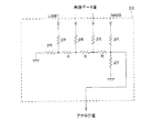
図8は、前記バッファメモリ5の入出力データと未読データ量との時間変化の一例を示すグラフである。図8(a)はバッファメモリ5に書込まれるデータを示し、図8(b)はバッファメモリ5から読出されるデータを示し、図8(c)はバッファメモリ5における未読データ量を示す。前述のように、時間軸方向に圧縮され、パケット化されたデータは、図8(a)において参照符in1,in2,in3,…で示すように、該バッファメモリ5に順次間欠に入力され、書込まれてゆく。また、該バッファメモリ5からは、前記パケットに対応して、図8(b)において参照符out1,out2,out3,…で示すように、時間軸方向に伸長され、連続したデータとなって読出されてゆく。これに対応して、未読データ量は、図8(c)において参照符α1で示すように増減を繰返す。
【0008】
なお、パケットデータは送信側から定期的に送られてくるとは限らず、一般的には、送信側のパケット化の際の都合によって、参照符in3,in7,in11,…で示すようにパケットが存在しない場合もある。この場合は、一次的に未読データ量が大きく減少するけれども、やがて徐々に増加し、該未読データ量の長時間平均は、参照符refで示す常に一定の値となる。
【0009】
ここで、通常、バッファメモリ5がオーバーフローおよびアンダーフローするまでの容量のマージンを同程度に設定するために、受信を開始してから該バッファメモリ5に半分までデータが蓄積された時点thから読出しが開始され、再生が行なわる。そして、送信側のサンプリングクロックと受信側のサンプリングクロックとの周波数が完全に一致している場合には、送信側の符号化周期と受信側の復号化周期とが等しく、したがってバッファメモリ5に書込まれるデータの平均速度とバッファメモリ5から読出されるデータの平均速度とが等しくなり、該バッファメモリ5の半分の容量が、前記参照符refで示す未読データ量の収束値となる。
【0010】
しかしながら、実際には、前述のように送信側のサンプリングクロックに対して受信側のサンプリングクロックが非同期であるので、それぞれのクロック周波数が微妙に異なったり、或いは他方に対して変動する。この結果、送信側の符号化処理の平均周期、つまりバッファメモリ5への書込みの平均周期と、受信側の復号化処理の平均周期、つまりバッファメモリ5からの読出しの平均周期とが異なり、未読データ量は、参照符α2やα3で示すように、時間の経過とともに前記半分の容量である値refからずれ、いずれはオーバーフローやアンダーフローが発生することになる。
【0011】
これを解決するために、たとえばIEEE1394規格によるデータ伝送では、IEEE1394バス上にサイクルマスタと呼ばれるノードが存在し、このサイクルマスタ上のタイマ情報をパケットに入れて送信し、バス上の他のノードのタイマに概ね基本周期(125μs)毎にコピーすることによって、各ノード間でタイマの時刻を合わせる仕組みが備わっており、送信側と受信側との双方で、自身のタイマを元に個別にサンプリングクロックを生成する。これによって、送受信装置間でサンプリングクロックの時間ずれは発生せず、受信側において前記サンプル点の重複や欠落を避けることができる。
【0012】
ここで、前記サイクルマスタの本来の働きは、サイクルスタートパケットと呼ばれるパケットを基本周期の最初に送出し、Isochronousパケットと呼ばれる帯域が保証されたパケットの送受信タイミングを決定することにあり、したがってこのサイクルマスタを必要とするのは、前記Isochronousパケットを使用する場合である。一方、前記IEEE1394規格においては、伝送レートが低い場合や他のパケットのトラフィックが少なく、帯域を保証する必要がない場合には、前記Isochronousパケットを使用せず、基本的なAsynchronousパケットと呼ばれるパケットのみを使用しても転送を行なえるようになっている。しかしながら、この場合、Isochronousパケットの処理およびサイクルマスタの処理が不要となり、ハードウェアが簡略化できる反面、送受信間で同期を行なう手段が存在しないので、時間ずれが発生し、前述のようなサンプル点の重複や欠落が発生する。
【0013】
また、バッファメモリ5の前記オーバーフローやアンダーフローを解決する別の手法として、データの受信側が送信側にコマンドを送ってフロー制御を行なって送信データの速度変更を要求することによって、受信側の独立したクロックでデータを再生しつつ、前記オーバーフローやアンダーフロー防止するという手法が、1394 TRADE ASSOCIATIONの技術文献「TA Document 1999015 AV/C Command Set for Rate Control of Isochronous Data Flow」に記載されている。この手法では、再生時にサンプル点の重複や欠落は発生せず、また送信側が送信データの速度を受信側に合わせて調整するので、受信側の独立したサンプリングクロックで再生でき、クロックのジッタが極めて少なく、非常に有効な手法である。
【0014】
しかしながら、この手法は、CDプレーヤなどの記録媒体に蓄積されたデータの再生には適用することが可能であるけれども、リアルタイムの放送データなどのように同時性のあるデータの場合には、送信側のデータ伝送速度を調整することが不可能なため、適用できない。また、この手法は、受信側から送信側に対して要求を行ない、送信ノードは要求を受けた受信ノードに対してのみ送信速度を合わせるので、1つの送信ノードに対して受信ノードが複数存在する場合には適用できない。さらにまた、送信側のデータを送出するハードウェアがこのようなフロー制御に対応し、前述のように送信側でCDからのデータの読出し速度を制御するような複雑な制御が必要になる。
【0015】
本発明の目的は、パケットによるデータ伝送においても、送信側から同期用データや同期クロックを伝送することなく、受信側において送信側と同期した再生処理を行い、サンプル点の重複や欠落なくデータを再生することができるデータ再生装置を提供することである。
【0016】
【課題を解決するための手段】
本発明のデータ再生装置は、受信したデータを再生する装置において、受信手段からの受信データを順次蓄積してゆくとともに、読出しクロックに応答して、一番古いデータから順次連続して読出しを行なうバッファメモリと、前記バッファメモリの未読データ量を算出する未読データ量算出手段と、前記未読データ量算出手段の出力を時間的に平滑化する平滑化手段と、前記平滑化手段からの出力に基づき、前記読出しクロックの周波数を変化させるクロック周波数変更手段と、前記読出しクロックに同期して、前記バッファメモリから読出されたデータの再生処理を行なう再生手段とを含むことを特徴とする。
【0017】
上記の構成によれば、受信したデータを再生するにあたって、受信データをバッファメモリに一時的に蓄積して、そのバッファメモリにおける未読データ量を未読データ量算出手段で算出し、クロック周波数変更手段が、その未読データ量を時間的に平滑化した出力に基づいて前記バッファメモリから再生手段への読出しクロックの周波数を変化させることで、バッファメモリにおける未読データの蓄積データ量を略一定に維持して、読出しを行う。
【0018】
したがって、送信側と受信側とが、特別なクロック信号や通信などで同期(連係)することなく、同時性のあるデータや、複数の再生装置に配信されるデータなどのように、再生装置側でデータの再生タイミングを任意に決定できないようなデータ、すなわちバッファメモリでの蓄積で、ジッタなどの時間のずれを吸収できないデータに対して、上記のように読出しクロックの周波数を変化することで、前記時間のずれを吸収することができる。
【0019】
また、本発明のデータ再生装置は、パケットに時間軸圧縮されて送信されるデータを受信して再生する装置において、受信手段からの受信データを順次蓄積してゆくとともに、読出しクロックに応答して、一番古いデータから順次連続して読出しを行なうバッファメモリと、前記バッファメモリの未読データ量を算出する未読データ量算出手段と、前記未読データ量算出手段の出力を時間的に平滑化する平滑化手段と、前記平滑化手段からの出力に基づき、前記読出しクロックの周波数を変化させるクロック周波数変更手段と、前記読出しクロックに同期して、前記バッファメモリから読出されたデータの再生処理を行なう再生手段とを含むことを特徴とする。
【0020】
上記の構成によれば、IEEE1394シリアルバスまたはUSBなどで実現される通信路を介して、送信側から一定間隔で送信されてくるパケットデータを受信して再生する装置において、受信データをバッファメモリに一時的に蓄積して、そのバッファメモリから、一番古いデータから順次連続して読出すことで、前記パケットデータの時間軸を伸長して、連続したデータに変換する。そして、前記バッファメモリにおける未読データ量を未読データ量算出手段で算出し、クロック周波数変更手段が、その未読データ量を時間的に平滑化した出力に基づいて前記バッファメモリから再生手段への読出しクロックの周波数を変化させることで、バッファメモリにおける未読データの蓄積データ量を略一定に維持して、読出しを行う。
【0021】
したがって、送信側と受信側とが、特別なクロック信号や通信などで同期(連係)することなく、同時性のあるデータや、複数の再生装置に配信されるデータなどのように、再生装置側でデータの再生タイミングを任意に決定できないようなデータ、すなわちバッファメモリでの蓄積で時間のずれを吸収できないデータに対して、上記のように読出しクロックの周波数を変化することで、前記時間のずれを吸収することができる。
【0022】
さらにまた、本発明のデータ再生装置では、前記読出しクロックを作成するクロック信号源は電圧制御型発振器から成り、前記未読データ量算出手段は、前記未読データ量が予め定める値以上であるか否かを表す1ビットの信号を出力し、前記クロック周波数変更手段は、前記1ビットの信号の出力に基づき、周波数を上昇すべき電圧と下降すべき電圧とを切換えて出力することを特徴とする。
【0023】
上記の構成によれば、未読データ量算出手段は、未読データ量が予め定める値以上であるか否かを表す1ビットの信号を出力し、それに応答して、クロック周波数変更手段は、周波数を下降すべき電圧、たとえばGND電位や、周波数を上昇すべき電圧、たとえばVcc電位を切換えて、前記電圧制御型発振器へ出力するだけで、前述のように読出し速度を一定に維持することができる。
【0024】
したがって、簡単な構成で、低コストに、かつ容易に実現することができる。
【0025】
また、本発明のデータ再生装置では、前記予め定める値は、前記バッファメモリの容量の半分であることを特徴とする。
【0026】
上記の構成によれば、送信側のクロック、すなわちバッファメモリへの書込みクロックと、読出しクロックとの差によるオーバーフローとアンダーフローとは、等しい確率で発生するので、周波数を上昇すべき電圧と下降すべき電圧との切換えの閾値となる未読データ量を前記バッファメモリの容量の半分とすることで、それらのフローを最も高い確率で防止することができる。
【0027】
さらにまた、本発明のデータ再生装置では、前記クロック周波数変更手段は、バッファメモリへのデータの入力開始時点から、未読データ量が予め定める値に達し、読出しが開始されるまでの間は、前記周波数を上昇すべき電圧と下降すべき電圧との中間値を出力することを特徴とする。
【0028】
上記の構成によれば、クロック周波数変更手段から電圧制御型発振器から成るクロック信号源への制御電圧を、初期に周波数を下降すべき電圧または上昇すべき電圧の一方に設定していると、読出しが始まっても電圧制御型発振器への制御電圧が収束せず、読出し速度が変化してゆくのに対して、読出しが開始される以前のバッファメモリへのデータの入力開始時点からそれらの電圧の中間値としておくことで、該読出し初期からクロックが規定の周波数で略安定しており、前記制御電圧が比較的安定し、読出し速度を一定に維持することができる。
【0029】
また、本発明のデータ再生装置では、前記読出しクロックを作成するクロック信号源は電圧制御型発振器から成り、前記クロック周波数変更手段は、前記未読データ量算出手段の出力データに対応したアナログ電圧を出力することを特徴とする。
【0030】
上記の構成によれば、前記未読データ量算出手段の出力データに対応して、前記電圧制御型発振器へ入力する制御電圧をアナログ電圧で細かく調整することができ、より高精度にクロック周波数を制御することができる。
【0031】
さらにまた、本発明のデータ再生装置では、前記電圧制御型発振器は、入力電圧の変化に対する出力周波数の変化が、中心電圧付近で小さく、かつ周辺電圧で大きくなる非線形な関数に設定されていることを特徴とする。
【0032】
上記の構成によれば、入力電圧が前記中心電圧付近に収束している定常状態では、該入力電圧が多少変動しても前記出力周波数を安定に維持することができ、これに対して、入力電圧が大きく変動した場合、前記出力周波数も大きく変化し、フィードバック制御によって前記入力電圧を前記中心電圧付近に効率良く復帰させることができる。
【0033】
また、本発明のデータ再生装置では、再生すべき受信データは、映像データおよび/または音声データであり、前記バッファメモリへは、前記映像および/または音声の成分以外を除いて記憶されることを特徴とする。
【0034】
上記の構成によれば、受信されたデータの内、バッファメモリへは、ヘッダや誤り訂正用の符号などの前記映像および/または音声の成分以外を除いて記憶される。
【0035】
したがって、前記バッファメモリのメモリ容量の消費を抑えるとともに、読出しにはそのような余分なデータを読出すためにより高い周波数のクロックが必要とならず、読出しのクロックを送信側と同じ周波数とすることができる。
【0036】
さらにまた、本発明のデータ再生装置では、再生すべき受信データは、1ビット音声データであることを特徴とする。
【0037】
上記の構成によれば、各ビットの重みの異なるマルチビットのデータでは、MSB付近のデータに伝送誤りが生じると、再生音声に大きな歪みが生じる可能性があるのに対して、1ビットのデータは各ビットの重みが相互に等しく、伝送誤りが生じても知覚できるような歪みが発生する可能性は小さい。
【0038】
したがって、1ビット音声データを用いることで、SNの大きなデータ伝送を行うことができる。
【0039】
また、本発明のデータ再生装置では、前記受信手段からの受信データが入力され、パケットデータに予め付されているパケット毎の順序を示す識別番号を識別し、受信パケット列中で前記識別番号が不連続になった場合には、消失パケットに代えて予め定める特定のデータを前記バッファメモリに書込むデータ補償手段をさらに備えることを特徴とする。
【0040】
上記の構成によれば、データ補償手段は、パケットの消失を判定すると、受信データに代えて、特定のデータを、消失したパケット数分、バッファメモリに書込みを行う。
【0041】
したがって、前記同時性のあるデータや複数の再生装置に配信されるデータなどのように再生装置側でデータの再生タイミングを任意に決定できないようなデータに好適である。
【0042】
さらにまた、本発明のデータ再生装置では、前記特定のデータは、再生信号のレベルが、一定値となるようなデータまたは0レベルとなるようなデータであることを特徴とする。
【0043】
上記の構成によれば、補償するデータを上記のようなデータとすることで、たとえば音声信号の場合には、聴感上のノイズを抑制することができる。
【0044】
【発明の実施の形態】
本発明の実施の一形態について、図1〜図3に基づいて説明すれば、以下のとおりである。
【0045】
図1は、パケットデータを受信して再生する本発明の実施の一形態の再生装置11の電気的構成を示すブロック図である。この再生装置11は、デジタルオーディオデータの再生装置であり、この図1では1チャネル分を示しているが、スピーカと再生装置およびアンプとが一体化された機器(図1におけるD/A変換器18以降を一体化した機器)などでは、これらの機器が並列に設けられ(図1におけるデコーダ17までが共用、前記D/A変換器18以降を複数チャネル)、送信側とともにチャネル毎の機器を設ける場合には、この図1の構成が並列に接続されることになり、したがって各再生装置11毎に任意に再生タイミングを決定できず、各チャネル間で同期して再生を行う必要のある装置である。
【0046】
送信側において、一定周期でサンプリングおよび符号化されてパケット化されたデータは、IEEE1394シリアルバスまたはUSBなどで実現される通信路12から受信回路13に間欠に入力され、制御回路14によって読出されてバッファメモリ15に順次書込まれ、蓄積される。一方、このバッファメモリ15からは、発振器16からのクロックによって一定間隔毎に連続してデータが読出され、デコーダ17によって音声データに復号化され、D/A変換器18においてアナログ信号となり、低域通過フィルタ19を通して、通信路20から図示しない増幅回路などに出力される。
【0047】
前記バッファメモリ15は、前記FIFOのメモリであり、入力データを順次蓄積してゆくとともに、その書込みとは非同期で、一番古いデータから順次読出しを行ない、読出された領域には順次新たなデータが再書込みされる。前記デコーダ17は、読出された1ワード分のデータを1サンプル分の音声データに復号化する。
【0048】
このようにバッファメモリ15から読出された後のデータは、発振器16からのクロックに同期して処理が行われる。すなわち、前記D/A変換器18のサンプリングクロックは、前記発振器16からのクロックか、またはそのクロックに同期して該D/A変換器18の内部で生成されるクロックとなり、送信側のサンプリングクロックとは非同期となっている。
【0049】
注目すべきは、本発明では、読出しクロックを作成する前記発振器16が可変周波数の発振器から成り、その発振周波数が、前記バッファメモリ15内の未読データ量に応じて変化されることである。具体的には、前記バッファメモリ15は、その内部の未読データ量が容量の半分を超えたか否かを示す1ビットのフラグ信号(一般的にハーフフラグ信号と呼ばれる)hfを出力する機能を有し、そのフラグ信号hfはスイッチ21を介してローパスフィルタ22に入力され、平滑化された後、前記発振器16に入力される。
【0050】
前記発振器16は、電圧制御型発振器(VCO)から成り、入力電圧が高くなる程、発振周波数が高くなる。一方、前記フラグ信号hfは、前記バッファメモリ15内の未読データ量が、半分を超えている場合には「1」、たとえばVccなどのハイレベルの電圧となり、前記半分を超えていない場合には「0」、たとえばGNDなどのローレベルの電圧となる。したがって、前記未読データ量が半分を超えている場合には前記発振器16の発振周波数が高くなってデータの読出し速度が速くなり、前記未読データ量が半分を超えていない場合には発振器16の発振周波数が低くなってデータの読出し速度が遅くなり、こうして常に前記未読データ量がバッファメモリ15の容量の半分となるように閉ループ制御が行われる。
【0051】
また、前記フラグ信号hfは制御回路14にも入力されている。この制御回路14は、前記フラグ信号hfに応答して、初期状態では「0」、該フラグ信号hfが最初に「1」となったタイミング以降は「1」となる切換え信号swを前記スイッチ21へ出力する。スイッチ21には、前記フラグ信号hfと、予め定める電圧Vhとが入力されており、前記切換え信号swが、「0」であるときには前記電圧Vhを前記ローパスフィルタ22へ出力し、「1」であるときには前記フラグ信号hfを前記ローパスフィルタ22へ出力する。
【0052】
前記電圧Vhは、前記フラグ信号hfの2つの電圧の中間値、たとえばVcc/2に選ばれている。したがって、発振器16は、バッファメモリ15からのデータの読出し開始までは一定の電圧Vhが入力されて、その電圧Vhに対応した予め定める周波数で発振を行い、バッファメモリ15からのデータの読出しが開始されると、前記電圧Vhに対応した周波数から前記フラグ信号hf、したがって未読データ量に対応した周波数に円滑に変移し、発振を行う。
【0053】
また、前記切換え信号swは、前記ANDゲート23の一方の入力にも入力されている。このANDゲート23の他方の入力には前記発振器16からのクロックが入力されており、出力が前記バッファメモリ15、デコーダ17およびD/A変換器18などへ出力される。したがって、前記切換え信号swは、クロックのイネーブル信号として作用し、該切換え信号swが、「0」であるとき、すなわち未読データ量がバッファメモリ15の容量の半分に達するまではクロックの出力を禁止し、「1」となると、すなわち未読データ量がバッファメモリ15の容量の半分を超えるとクロックの出力を許可し、すなわちバッファメモリ15からのデータの読出しを許容する。
【0054】
図2は、上述のように構成される再生装置11におけるバッファメモリ15の入出力データと未読データ量との時間変化の一例を示すグラフである。この図2は前述の図8に対応し、図2(a)はバッファメモリ15に書込まれるデータを示し、図2(b)はバッファメモリ15から読出されるデータを示し、図2(c)はバッファメモリ15における未読データ量を示す。また、図2(d)は前記フラグ信号hfを示し、図2(e)はローパスフィルタ22への入出力を示す。
【0055】
先ず、初期状態またはデータ受信を行なっていないアイドル状態では、制御回路14からの切換え信号swが「0」とされる。これによって、スイッチ21はローパスフィルタ22に対して定電圧Vhを出力する。前記電圧Vhは前記フラグ信号hfの振幅変化幅の1/2のレベルに設定されており、直流成分は該ローパスフィルタ22を通過するので、発振器16にはこの定電圧Vhが供給される。ここで発振器16は、前記電圧Vhを入力したときに、所望のサンプリングクロック周波数と同じ周波数で発振するように設計されている。このクロックは前記ANDゲート23で阻止されて出力されず、またバッファメモリ15の内部は空の状態である。
【0056】
通信路12を通して他のノードからのデータの受信が開始されると、受信されたパケットは、受信回路13に入力され、該受信回路13がデータを受信したことを制御回路14に報知することで、先ずパケット内のヘッダが該制御回路14によって受信回路13から読出される。たとえば、IEEE1394による通信方式では、ヘッダにはパケット内に含まれるデータ数が格納されており、制御回路14はこのデータ数だけパケット中のオーディオデータのみを受信回路13からバッファメモリ15に書込む。パケットにヘッダなどが含まれず、パケット全体がデータのみで構成されるような通信方式の場合には、パケット内の最初から最後までのデータを制御回路14がバッファメモリ15に書込めばよい。以上の動作がパケット毎に繰返される。こうして前述のように、時間軸方向に圧縮され、パケット化されたデータが、図2(a)において参照符IN1,IN2,IN3,…で示すように、該バッファメモリ15に順次入力され、書込まれてゆく。
【0057】
そして、時刻THにおいて、バッファメモリ15の内部にデータが半分まで蓄積されると、該バッファメモリ15から出力されるフラグ信号hfが図2(d)で示すように「1」となり、制御回路14はこの時点から一連のデータ受信が全て完了するまで、前記切換え信号swを「1」にして保持する。これによって、再生中はスイッチ21は前記フラグ信号hfをローパスフィルタ22を介して発振器16に与えるとともに、ANDゲート23がそのクロックの出力を許可し、発振器16からのクロックが出力され続ける。この結果、バッファメモリ15には前記時刻THから読出しクロックが入力され、図2(b)において参照符OUT1,OUT2,OUT3,…で示すように、符号化されたデータが1サンプル分ずつ一定間隔で読出され、時間軸方向に伸長される。読出されたデータは、デコーダ17で復号化され、D/A変換器18においてアナログ信号に変換された後、出力される。
【0058】
ここで、前記時刻THにおいて、スイッチ21がフラグ信号hf側に切換わった直後の発振器16の入力電圧は、ローパスフィルタ22の効果によって直ちに変化せず、したがってクロックの周期も直ちには変化しない。このクロックに応答して、上述のようにバッファメモリ15からのデータの読出しが開始されると、未読データ量は、図2(c)において参照符βで示すように増減を繰返す。これによって、前記フラグ信号hfは図2(d)に示すように変化し、スイッチ21を介するローパスフィルタ22への入力も図2(e)において参照符γ1で示すように前記フラグ信号hfに対応した信号となり、この信号が該ローパスフィルタ22で平滑化され、参照符γ2で示すように、時間変化のほとんどない波形となって発振器16へ入力され、該発振器16からは周波数の安定したクロックが出力される。
【0059】
ここで、前記バッファメモリ15からの読出しが開始されるまでの期間、電圧Vhをローパスフィルタ22へ供給する構成がない場合は、該ローパスフィルタ22の出力は、図2(e)において参照符γ3で示すように、前記電圧Vhに到達するまでに時間がかかり、その間クロックが不安定となってしまうのに対して、前記のように定電圧Vhを供給することによって、前記読出し開始の前後でローパスフィルタ22の出力として、未読データ量を一定にするような電圧変化がほとんどない波形が得られることになり、クロック周波数を安定させることができる。
【0060】
以上のように構成することによって、従来では、送信側のサンプリングクロックが受信側のサンプリングクロックに対して周波数が微妙に高い場合は、前記図8(c)において参照符α2で示すように未読データ量が時間と共に増加し、オーバーフローを生じていたのに対して、本発明の再生装置11では、前記未読データ量の増加によってフラグ信号hfが「1」となる割合が多くなって読出しのクロックの周波数も微妙に増加するので、図2(c)において参照符βで示すように、そのような不具合が生じることはなく、未読データ量を常に略一定にすることができる。
【0061】
同様に、従来では、送信側のサンプリングクロックが受信側のサンプリングクロックに対して周波数が微妙に低い場合は、前記図8(c)において参照符α3で示すように未読データ量が時間と共に減少し、アンダーフローを生じていたのに対して、本発明の再生装置11では、前記未読データ量の減少によってフラグ信号hfが「0」となる割合が多くなって読出しのクロックの周波数も微妙に減少するので、図2(c)において参照符βで示すように、そのような不具合が生じることはなく、未読データ量を常に略一定にすることができる。
【0062】
このように前記フラグ信号hfによって発振器16にバッファメモリ15の未読データ量がフィードバックされ、クロックの周期は送信側の符号化周期、つまりサンプリング周期と同じになるように制御され、前記未読データ量の平均値が一定量に保たれるので、バッファメモリ15のオーバーフローやアンダーフローは発生せず、再生時にサンプル点の重複や欠落は発生しない。したがって、送信側から一定間隔で送信されてくるパケットデータを受信して再生するにあたって、送信側と受信側とが、特別なクロック信号や通信などで同期(連係)することなく、同時性のあるデータや、複数の再生装置に配信されるデータなどのように、再生装置側でデータの再生タイミングを任意に決定できないようなデータ、すなわちバッファメモリ15での蓄積で時間のずれを吸収できないデータに対して、上記のように読出しクロックの周波数を変化することで、前記時間のずれを吸収することができる。
【0063】
ここで、クロックの周波数の変動要因はバッファメモリ15への書込み周期の乱れによるものであるが、図2(a)において参照符IN3,IN7,IN11,…で示すように、パケットが一時途切れても、パケット中のデータの長時間に亘る平均周期は、送信側の符号化周期に一致し、常に一定となるので、バッファメモリ15への書込み周期の長時間平均も一定となり、この長時間平均を行なうローパスフィルタ22の効果によってクロックの変動を避けることができる。
【0064】
また、本発明の再生装置11では、発振器16を電圧制御型発振器で構成し、その発振器16へは、バッファメモリ15からのフラグ信号hfをローパスフィルタ22で平滑化して与えるようにし、前記フラグ信号hfが、その発振器16の発振周波数を上昇すべき電圧と下降すべき電圧とを切換えて出力するとともに、読出し初期においては、制御回路14がスイッチ21を切換えて、両電圧の中間値である定電圧Vhを入力するので、読出し初期から発振器16の入力電圧が比較的安定し、読出し速度を一定に維持することができる。
【0065】
さらにまた、前記発振器16は、その入出力特性が、図3で示すように、入力電圧の変化に対する出力周波数の変化が、中心電圧付近で小さく、かつ周辺電圧で大きくなる非線形な関数に設定されている。これによって、前述のように通常再生時は前記フラグ信号hfの中心電圧である前記定電圧Vhで平衡状態にある該発振器16の入力電圧が多少変動しても、出力周波数を安定に維持することができ、これに対して前記入力電圧が大きく変動した場合、前記出力周波数も大きく変化し、フィードバック制御によって前記フラグ信号hfをローパスフィルタ22で平滑化した電圧を前記定電圧Vh付近に効率良く復帰させることができる。
【0066】
本発明の実施の他の形態について、図4および図5に基づいて説明すれば、以下のとおりである。
【0067】
図4は、本発明の実施の他の形態の再生装置31の電気的構成を示すブロック図である。この再生装置31は、上述の再生装置11に類似し、対応する部分には同一の参照符号を付して、その説明を省略する。注目すべきは、この再生装置31では、フィードバック制御を行なうための信号が、前記フラグ信号hfのような1ビットの信号ではなく、多ビットのデジタル信号をアナログ値に変換した信号であることである。また、再生処理部分は、デジタルオーディオデータが2値化された1ビットオーディオデータの再生処理を行なうことである。
【0068】
具体的には、制御回路38によってカウンタ32およびバッファメモリ15が最初に初期化され、その後、前記制御回路38からバッファメモリ15への書込みクロックと、後述の読出しクロックとがカウンタ32に入力され、それぞれのクロックによって数値を増加または減少させて得られた差分値、したがってバッファメモリ15の未読データ量の計数値がD/A変換器33によってアナログ値に変換される。そのアナログ値は、前記スイッチ21およびローパスフィルタ22を介して、クロックの発振器34に入力される。
【0069】
図5は、前記D/A変換器33の一構成例を示すブロック図である。このD/A変換器33は、抵抗を組合わせた簡単な構成で実現されるD/A変換器であり、4ビット入力の例を示している。前記カウンタ32からの未読データ量の計数値のデジタルデータが図5の上方からパラレルに入力され、下方からアナログ値が出力される。入力ビット数が多い場合は、抵抗を図5の横方向に増やすだけでよい。
【0070】
前記発振器34は、前述のように電圧制御型発振器から成り、前記1ビットオーディオデータのサンプリング周波数に対応した発振周波数のクロックを出力する。このクロックは、デコーダ35および1ビットオーディオデータのD/A変換器36へ出力されるとともに、分周器37で分周された後、バッファメモリ15の読出しクロックとして使用される。
【0071】
上述のように構成される再生装置31では、データの読出しが開始されると、前記ローパスフィルタ22には、前記図2(d)および図2(e)において参照符γ1で示すような前記フラグ信号hfに代えて、図2(c)において参照符βで示す未読データ量のアナログ値が入力され、前記再生装置11と同様のフィードバックによる周波数制御が行われる。これによって、前記再生装置11に比べて、構成は複雑になるものの、より高精度にクロック周波数を制御することができる。
【0072】
また、デジタルオーディオデータとして、2値化された1ビットオーディオデータを使用する場合、バッファメモリ15から読出されるデータ1ワード中の1ビットが1サンプルに相当する。したがって、1ワード中のビット数をnとすると、バッファメモリ15から1回データを読出す間にサンプリング処理がn回行われることになるので、該バッファメモリ15へは、サンプリング用のクロックをn分周したクロックが分周器37で生成され、入力される。
【0073】
ここで、発振器34は、前記定電圧Vhを入力したときに、1ビットオーディオ再生のための所望のサンプリングクロック周波数と同じ周波数で発振するように設計されている。1ビットオーディオの場合、デコーダ35の内部では1ワードのデータを1ビットに変換する並列/直列変換処理のみを行ない、D/A変換器36の内部では低域通過フィルタによる処理のみを行なうことでアナログ信号に変換することができる。
【0074】
このように1ビットオーディオデータで伝送することで、各ビットの重みの異なるマルチビットのデータでは、MSB付近のデータに伝送誤りが生じると、再生音声に大きな歪みが生じる可能性があるのに対して、該1ビットオーディオデータは各ビットの重みが相互に等しく、伝送誤りが生じても知覚できるような歪みが発生する可能性は小さく、SNの大きなデータ伝送を行うことができる。
【0075】
さらにまた、伝送中のエラーによって、パケットが正しく受信できずに消失する場合がある。このような場合には、送信データの量と受信データの量とが異なり、ローパスフィルタ22へ入力される信号の平均レベルが変化し、一時的にサンプリング周波数が乱れることになる。この乱れは前述のフィードバック制御によっていずれ回復するけれども、この再生装置31では、そのような乱れを防止する対策を講じており、以下に説明する。なお、以下の説明では、各パケットに含まれるデータ量は一定量Kとし、消失したパケット中のデータ量もKである場合を想定している。
【0076】
先ず、図示しない送信側からは、パケットの識別が可能な通し番号がヘッダ部分に入れて送信される。そのパケットを受信すると、制御回路38は、ヘッダ中のこの番号をパケット毎に確認する。もし前回受信したパケットの番号に対して今回受信したパケットの番号が連続していない場合は、該制御回路38はその間のパケットが伝送エラーによって消失したと判断し、今回受信したパケットの番号から前回受信したパケットの番号を減算し、その結果からさらに1を減算することで消失分のパケット数を算出する。そして、消失したパケット数×Kの量の再生用データ量をダミーデータとしてバッファメモリ15へ書込む。
【0077】
これによって、パケットが伝送中にエラーで消失しても、送信されたパケット中のデータ量と同じ量のデータがバッファメモリ15へ書込まれ、該バッファメモリ15内の未読データ量の平均値が変化することなく、したがってサンプリング周波数が乱れることを防止することができる。
【0078】
なお、前記ダミーデータは、バッファメモリ15から読出されて音声データとして再生されると、聴感上のノイズとなるので、D/A変換器36から出力される際に振幅が0レベルとなるか、または一定値を維持することが望ましい。これには、前述のようにオーディオデータが1ビットオーディオデータである場合、再生データのビット列が1と0とを交互に繰返すようなデータを書込むことで実現することができる。この場合、平均値が0レベルとなり、したがって再生レベルを0レベルに保持し、聴感上のノイズを極力抑えることができる。
【0079】
以上の実施形態は何れもオーディオデータを対象に説明したけれども、周期的に再生処理が行われる映像データなどに対しても同様に適用できることは明らかである。また、パケットデータに限らず、連続して送信されてくるデータに対しても、ジッタを除去するために使用することができる。
【0080】
【発明の効果】
本発明のデータ再生装置は、以上のように、受信したデータを再生するにあたって、受信データをバッファメモリに一時的に蓄積して、そのバッファメモリにおける未読データ量を未読データ量算出手段で算出し、クロック周波数変更手段が、その未読データ量を平滑化した出力に基づいて前記バッファメモリから再生手段への読出しクロックの周波数を変化させることで、バッファメモリにおける未読データの蓄積データ量を略一定に維持して、読出しを行う。
【0081】
それゆえ、送信側と受信側とが、特別なクロック信号や通信などで同期(連係)することなく、同時性のあるデータや、複数の再生装置に配信されるデータなどのように、再生装置側でデータの再生タイミングを任意に決定できないようなデータ、すなわちバッファメモリでの蓄積で、ジッタなどの時間のずれを吸収できないデータに対して、上記のように読出しクロックの周波数を変化することで、前記時間のずれを吸収することができる。
【0082】
また、本発明のデータ再生装置は、以上のように、送信側から一定間隔で送信されてくるパケットデータを受信して再生する装置において、受信データをバッファメモリに一時的に蓄積して、そのバッファメモリから、一番古いデータから順次連続して読出すことで、前記パケットデータの時間軸を伸長して、連続したデータに変換する。そして、前記バッファメモリにおける未読データ量を未読データ量算出手段で算出し、クロック周波数変更手段が、その未読データ量を平滑化した出力に基づいて前記バッファメモリから再生手段への読出しクロックの周波数を変化させることで、バッファメモリにおける未読データの蓄積データ量を略一定に維持して、読出しを行う。
【0083】
それゆえ、送信側と受信側とが、特別なクロック信号や通信などで同期(連係)することなく、同時性のあるデータや、複数の再生装置に配信されるデータなどのように、再生装置側でデータの再生タイミングを任意に決定できないようなデータ、すなわちバッファメモリでの蓄積で時間のずれを吸収できないデータに対して、上記のように読出しクロックの周波数を変化することで、前記時間のずれを吸収することができる。
【0084】
さらにまた、本発明のデータ再生装置は、以上のように、前記読出しクロックを作成するクロック信号源を電圧制御型発振器とし、未読データ量算出手段は、未読データ量が予め定める値以上であるか否かを表す1ビットの信号を出力し、それに応答して、クロック周波数変更手段は、周波数を下降すべき電圧、たとえばGND電位や、周波数を上昇すべき電圧、たとえばVcc電位を切換えて、前記電圧制御型発振器へ出力することで、前述のように読出し速度を一定に維持する。
【0085】
それゆえ、簡単な構成で、低コストに、かつ容易に実現することができる。
【0086】
また、本発明のデータ再生装置は、以上のように、前記予め定める値を、前記バッファメモリの容量の半分とする。
【0087】
それゆえ、送信側のクロック、すなわちバッファメモリへの書込みクロックと読出しクロックとの差によるオーバーフローとアンダーフローとを、最も高い確率で防止することができる。
【0088】
さらにまた、本発明のデータ再生装置は、以上のように、前記クロック周波数変更手段が、バッファメモリへのデータの入力開始時点から、未読データ量が予め定める値に達し、読出しが開始されるまでの間は、前記周波数を上昇すべき電圧と下降すべき電圧との中間値を出力する。
【0089】
それゆえ、読出しが開始される以前のバッファメモリへのデータの入力開始時点からクロックが規定の周波数で略安定しており、読出しが開始時点では前記制御電圧が比較的安定し、読出し速度を一定に維持することができる。
【0090】
また、本発明のデータ再生装置は、前記読出しクロックを作成するクロック信号源を電圧制御型発振器とし、前記クロック周波数変更手段は、前記未読データ量算出手段の出力データに対応したアナログ電圧を出力する。
【0091】
それゆえ、未読データ量に対応して、前記電圧制御型発振器へ入力する制御電圧をアナログ電圧で細かく調整することができ、より高精度にクロック周波数を制御することができる。
【0092】
さらにまた、本発明のデータ再生装置は、以上のように、前記電圧制御型発振器を、入力電圧の変化に対する出力周波数の変化が、中心電圧付近で小さく、かつ周辺電圧で大きくなる非線形な関数に設定する。
【0093】
それゆえ、入力電圧が前記中心電圧付近に収束している定常状態では、該入力電圧が多少変動しても前記出力周波数を安定に維持することができ、これに対して、入力電圧が大きく変動した場合、前記出力周波数も大きく変化し、フィードバック制御によって前記入力電圧を前記中心電圧付近に効率良く復帰させることができる。
【0094】
また、本発明のデータ再生装置は、以上のように、再生すべき受信データを、映像データおよび/または音声データとし、前記バッファメモリへは、ヘッダや誤り訂正用の符号などの前記映像および/または音声の成分以外を除いて記憶する。
【0095】
それゆえ、前記バッファメモリのメモリ容量の消費を抑えるとともに、読出しのクロックを送信側と同じ周波数とすることができる。
【0096】
さらにまた、本発明のデータ再生装置は、以上のように、再生すべき受信データを、各ビットの重みが相互に等しく、伝送誤りが生じても知覚できるような歪みが発生する可能性が小さい1ビット音声データとする。
【0097】
それゆえ、SNの大きなデータ伝送を行うことができる。
【0098】
また、本発明のデータ再生装置は、以上のように、データ補償手段が、受信したパケットデータに予め付されているパケット毎の順序を示す識別番号を識別し、受信パケット列中で前記識別番号が不連続になった場合には、消失パケットに代えて予め定める特定のデータを前記バッファメモリに書込む。
【0099】
それゆえ、前記同時性のあるデータや複数の再生装置に配信されるデータなどのように再生装置側でデータの再生タイミングを任意に決定できないようなデータに好適である。
【0100】
さらにまた、本発明のデータ再生装置は、以上のように、前記特定のデータを、再生信号のレベルが、一定値となるようなデータまたは0レベルとなるようなデータとする。
【0101】
それゆえ、たとえば音声信号の場合には、聴感上のノイズを抑制することができる。
【図面の簡単な説明】
【図1】パケットデータを受信して再生する本発明の実施の一形態の再生装置の電気的構成を示すブロック図である。
【図2】図1で示す再生装置におけるバッファメモリの入出力データと未読データ量との時間変化の一例を示すグラフである。
【図3】発振器の入力電圧の変化に対する出力周波数の変化を示すグラフである。
【図4】本発明の実施の他の形態の再生装置の電気的構成を示すブロック図である。
【図5】図4で示す再生装置におけるD/A変換器の一構成例を示すブロック図である。
【図6】サンプル点が欠落した場合の再生波形を示す図である。
【図7】典型的な従来技術の再生装置の電気的構成を示すブロック図である。
【図8】図7で示す再生装置におけるバッファメモリの入出力データと未読データ量との時間変化の一例を示すグラフである。
【符号の説明】
11,31 再生装置
12,19 通信路
13 受信回路(受信手段)
14 制御回路
15 バッファメモリ(未読データ量算出手段、クロック周波数変更手段)
16,34 発振器(クロック信号源、電圧制御型発振器)
17,35 デコーダ(再生手段)
18,36 D/A変換器
21 スイッチ(クロック周波数変更手段)
22 ローパスフィルタ(平滑化手段)
23 ANDゲート
32 カウンタ(未読データ量算出手段、クロック周波数変更手段)
33 D/A変換器(クロック周波数変更手段)
37 分周器
38 制御回路(データ補償手段)[0001]
TECHNICAL FIELD OF THE INVENTION
The present invention is suitably implemented for data in which the reproduction timing of data cannot be arbitrarily determined on the reproduction device side, such as data with synchronization such as video and audio and data distributed to a plurality of reproduction devices, The present invention relates to an apparatus for reproducing received data into a video signal and an audio signal.
[0002]
[Prior art]
Conventionally, in order to simplify a transmission path, a device that receives and reproduces digital audio data transmitted from a transmitting side without a clock signal on a receiving side has been used. In such a configuration, when data is reproduced based on a sampling clock that is not synchronized with the received data, a time lag occurs between the data and the sampling clock because the periods of the data and the sampling clock do not completely match. . For this reason, when the sampling frequency of the receiving side is higher than that of the transmitting side, the same sample point is reproduced twice (duplicated) continuously as shown in FIG. When the sampling frequency on the receiving side is low, there is a problem that a reproduced waveform becomes discontinuous due to occurrence of a sample point (loss) which is not reproduced as shown in FIG. 6B.
[0003]
In order to solve such a problem, for example, IEC60958, which is a standard of a digital audio interface, transmits data after bi-phase modulation. As a result, the clock signal component synchronized with the data is superimposed on the data and transmitted. When the reception data is input to the PLL, a clock signal having the same cycle as the reception data can be obtained as the output. . Further, by generating a sampling clock synchronized with the clock and reproducing the data, a time lag of the sampling clock does not occur between the transmitting and receiving devices, and the duplication or omission of the sample points of the reproduced data as described above is prevented. Can be avoided.
[0004]
[Problems to be solved by the invention]
However, in the above-described method, when data is continuously transmitted, a clock synchronized with the received data can be generated and the audio data can be reproduced without any problem, but the data is compressed in the time axis direction. In the case of intermittent transmission as a packet, there is a period during which there is no data during reception, a clock for reproduction cannot be obtained, and such a method cannot be used. For this reason, in an apparatus that receives and reproduces packet data, the packet data is stored in a buffer memory such as a FIFO (First In First Out) and is stored in a fixed amount from the buffer memory using a clock generated independently on the receiving side. It is common practice to read out data from the oldest data at intervals and reproduce the data.
[0005]
FIG. 7 is a block diagram showing an electrical configuration of a typical conventional reproducing
[0006]
The data read from the
[0007]
FIG. 8 is a graph showing an example of a time change between the input / output data of the
[0008]
Note that the packet data is not always sent from the transmitting side at regular intervals. Generally, the packet data is indicated by reference numerals in3, in7, in11,. May not be present. In this case, although the amount of unread data temporarily decreases largely, it gradually increases gradually, and the long-term average of the amount of unread data always becomes a constant value indicated by the reference numeral ref.
[0009]
Here, usually, in order to set the capacity margins before the
[0010]
However, in practice, as described above, the sampling clock on the receiving side is asynchronous with respect to the sampling clock on the transmitting side, so that the respective clock frequencies are slightly different or fluctuate with respect to the other. As a result, the average period of the encoding process on the transmitting side, that is, the average period of writing to the
[0011]
In order to solve this problem, for example, in data transmission according to the IEEE 1394 standard, a node called a cycle master exists on the IEEE 1394 bus, timer information on this cycle master is transmitted in a packet and transmitted to other nodes on the bus. The timer is provided with a mechanism for adjusting the time of the timer between the nodes by copying approximately every basic cycle (125 μs). Both the transmitting side and the receiving side individually use the sampling clock based on their own timer. Generate As a result, there is no time lag of the sampling clock between the transmitting and receiving devices, and it is possible to avoid duplication or omission of the sample points on the receiving side.
[0012]
Here, the original function of the cycle master is to transmit a packet called a cycle start packet at the beginning of a basic cycle and to determine the transmission / reception timing of a band-guaranteed packet called an isochronous packet. A master is required when using the Isochronous packet. On the other hand, in the IEEE 1394 standard, when the transmission rate is low or the traffic of other packets is small, and there is no need to guarantee the bandwidth, the isochronous packet is not used, and only a packet called a basic asynchronous packet is used. The transfer can be performed by using. However, in this case, the processing of the isochronous packet and the processing of the cycle master become unnecessary, and the hardware can be simplified. On the other hand, since there is no means for synchronizing between transmission and reception, a time lag occurs, and the sampling point as described above occurs. Duplication or omission occurs.
[0013]
As another method for solving the overflow or underflow of the
[0014]
However, although this method can be applied to the reproduction of data stored on a recording medium such as a CD player, in the case of synchronous data such as real-time broadcast data, the transmitting side It is not applicable because it is impossible to adjust the data transmission rate of Further, in this method, a request is made from the receiving side to the transmitting side, and the transmitting node adjusts the transmission speed only to the receiving node that has received the request, so that there are a plurality of receiving nodes for one transmitting node. Not applicable in cases. Furthermore, the hardware for transmitting the data on the transmission side corresponds to such flow control, and complicated control for controlling the data reading speed from the CD on the transmission side as described above is required.
[0015]
An object of the present invention is to perform a reproduction process synchronized with a transmission side on a reception side without transmitting synchronization data or a synchronization clock from a transmission side even in data transmission by a packet, and to reproduce data without duplication or loss of sample points. An object of the present invention is to provide a data reproducing device capable of reproducing.
[0016]
[Means for Solving the Problems]
A data reproducing apparatus according to the present invention is a data reproducing apparatus for reproducing received data, sequentially accumulates data received from a receiving means, and sequentially reads data from an oldest data in response to a read clock. A buffer memory, an unread data amount calculating unit that calculates an unread data amount of the buffer memory, a smoothing unit that temporally smoothes an output of the unread data amount calculating unit, and a buffer memory based on an output from the smoothing unit. Clock frequency changing means for changing the frequency of the read clock; and reproducing means for reproducing data read from the buffer memory in synchronization with the read clock.
[0017]
According to the above configuration, when reproducing the received data, the received data is temporarily stored in the buffer memory, the unread data amount in the buffer memory is calculated by the unread data amount calculation means, and the clock frequency changing means is By changing the frequency of the read clock from the buffer memory to the reproducing means based on the output obtained by temporally smoothing the unread data amount, the accumulated data amount of the unread data in the buffer memory can be maintained substantially constant. And read out.
[0018]
Therefore, the transmission side and the reception side do not synchronize (cooperate) with a special clock signal, communication, or the like. By changing the frequency of the read clock as described above for data for which data reproduction timing cannot be determined arbitrarily, that is, for data that cannot absorb a time lag such as jitter due to accumulation in the buffer memory, The time lag can be absorbed.
[0019]
Further, the data reproducing apparatus of the present invention is a device for receiving and reproducing data transmitted by being time-axis-compressed into a packet. The data reproducing apparatus sequentially accumulates data received from a receiving unit and responds to a read clock. A buffer memory that sequentially reads data from the oldest data, an unread data amount calculating unit that calculates an unread data amount of the buffer memory, and a smoothing unit that temporally smoothes an output of the unread data amount calculating unit. Means for changing the frequency of the read clock based on the output from the smoothing means, and reproduction for performing a reproduction process of data read from the buffer memory in synchronization with the read clock. Means.
[0020]
According to the above configuration, in a device that receives and reproduces packet data transmitted from the transmission side at regular intervals via a communication path realized by an IEEE 1394 serial bus or USB, the received data is stored in the buffer memory. The packet data is temporarily stored and sequentially read out from the buffer memory sequentially from the oldest data, thereby extending the time axis of the packet data and converting the packet data into continuous data. Then, the amount of unread data in the buffer memory is calculated by the unread data amount calculating means, and the clock frequency changing means reads the clock from the buffer memory to the reproducing means based on the output obtained by temporally smoothing the unread data amount. By changing the frequency, the amount of unread data stored in the buffer memory is kept substantially constant and reading is performed.
[0021]
Therefore, the transmission side and the reception side do not synchronize (cooperate) with a special clock signal, communication, or the like. By changing the frequency of the read clock as described above for data for which the data reproduction timing cannot be determined arbitrarily, that is, for data that cannot absorb the time lag due to accumulation in the buffer memory, Can be absorbed.
[0022]
Still further, in the data reproducing apparatus according to the present invention, the clock signal source for generating the read clock includes a voltage-controlled oscillator, and the unread data amount calculation unit determines whether the unread data amount is equal to or greater than a predetermined value. And the clock frequency changing means switches and outputs the voltage to be increased and the voltage to be decreased based on the output of the 1-bit signal.
[0023]
According to the above configuration, the unread data amount calculation unit outputs a 1-bit signal indicating whether or not the unread data amount is equal to or greater than a predetermined value, and in response, the clock frequency changing unit changes the frequency. As described above, the reading speed can be maintained constant only by switching the voltage to be lowered, for example, the GND potential, or the voltage to be raised in frequency, for example, the Vcc potential, and outputting the same to the voltage-controlled oscillator.
[0024]
Therefore, it can be easily realized with a simple configuration at low cost.
[0025]
Further, in the data reproducing apparatus according to the present invention, the predetermined value is a half of the capacity of the buffer memory.
[0026]
According to the configuration described above, the overflow and the underflow due to the difference between the clock on the transmission side, that is, the write clock to the buffer memory and the read clock occur with equal probability, so that the voltage whose frequency should be raised and the voltage that should be dropped fall. By setting the amount of unread data, which is the threshold value for switching to the power voltage, to be half of the capacity of the buffer memory, such flows can be prevented with the highest probability.
[0027]
Still further, in the data reproducing apparatus according to the present invention, the clock frequency changing unit may be configured so that the unread data amount reaches a predetermined value from the time when the input of data to the buffer memory is started to the time when reading is started. It is characterized in that it outputs an intermediate value between the voltage to increase the frequency and the voltage to decrease.
[0028]
According to the above configuration, if the control voltage from the clock frequency changing means to the clock signal source composed of the voltage controlled oscillator is initially set to one of the voltage to decrease the frequency and the voltage to increase the frequency, the reading is performed. Although the control voltage to the voltage-controlled oscillator does not converge and the read speed changes even when the read operation starts, the voltage By setting it to an intermediate value, the clock is substantially stable at a specified frequency from the beginning of the reading, the control voltage is relatively stable, and the reading speed can be kept constant.
[0029]
In the data reproducing apparatus of the present invention, the clock signal source for generating the read clock includes a voltage-controlled oscillator, and the clock frequency changing unit outputs an analog voltage corresponding to output data of the unread data amount calculating unit. It is characterized by doing.
[0030]
According to the above configuration, the control voltage input to the voltage-controlled oscillator can be finely adjusted with an analog voltage in accordance with the output data of the unread data amount calculation means, and the clock frequency can be controlled with higher accuracy. can do.
[0031]
Still further, in the data reproducing apparatus according to the present invention, the voltage-controlled oscillator is set to a non-linear function in which a change in an output frequency with respect to a change in an input voltage is small near a center voltage and large at a peripheral voltage. It is characterized by.
[0032]
According to the above configuration, in a steady state where the input voltage converges near the center voltage, the output frequency can be stably maintained even if the input voltage slightly changes. When the voltage fluctuates significantly, the output frequency also changes greatly, and the input voltage can be efficiently returned to near the center voltage by feedback control.
[0033]
In the data reproducing apparatus of the present invention, the received data to be reproduced is video data and / or audio data, and is stored in the buffer memory except for components other than the video and / or audio components. Features.
[0034]
According to the above configuration, of the received data, the buffer memory is stored excluding components other than the video and / or audio components such as a header and an error correction code.
[0035]
Therefore, the consumption of the memory capacity of the buffer memory is suppressed, and the reading does not require a higher frequency clock to read such extra data, and the reading clock is set to the same frequency as the transmitting side. Can be.
[0036]
Still further, in the data reproducing apparatus of the present invention, the received data to be reproduced is 1-bit audio data.
[0037]
According to the above configuration, in the case of multi-bit data having different weights for each bit, if a transmission error occurs in data near the MSB, there is a possibility that a large distortion may occur in a reproduced sound, whereas a 1-bit data The weight of each bit is equal to each other, and there is little possibility that perceptible distortion will occur even if a transmission error occurs.
[0038]
Therefore, data transmission with a large SN can be performed by using 1-bit audio data.
[0039]
Further, in the data reproducing apparatus of the present invention, the received data from the receiving means is input, and an identification number indicating an order for each packet added to the packet data in advance is identified. In a case where the data becomes discontinuous, a data compensating means for writing predetermined specific data into the buffer memory instead of the lost packet is further provided.
[0040]
According to the above configuration, when the data compensating unit determines that the packet has been lost, the data compensating unit writes specific data in place of the received data to the buffer memory for the number of lost packets.
[0041]
Therefore, the present invention is suitable for data in which the reproduction timing of the data cannot be arbitrarily determined on the reproduction device side, such as the data with synchronization and the data distributed to a plurality of reproduction devices.
[0042]
Still further, in the data reproducing apparatus according to the present invention, the specific data is data such that a level of a reproduced signal is a constant value or a zero level.
[0043]
According to the above configuration, by making the data to be compensated be the above-described data, for example, in the case of an audio signal, it is possible to suppress audible noise.
[0044]
BEST MODE FOR CARRYING OUT THE INVENTION
One embodiment of the present invention will be described below with reference to FIGS.
[0045]
FIG. 1 is a block diagram showing an electrical configuration of a reproducing apparatus 11 according to one embodiment of the present invention for receiving and reproducing packet data. The playback device 11 is a playback device for digital audio data. Although FIG. 1 shows one channel, the playback device 11 is a device in which a speaker, a playback device, and an amplifier are integrated (the D / A converter in FIG. 1). 18 and the like), these devices are provided in parallel (the
[0046]
On the transmitting side, the packetized data sampled and encoded at a fixed period is intermittently input to the receiving
[0047]
The
[0048]
The data read from the
[0049]
It should be noted that, in the present invention, the
[0050]
The
[0051]
Further, the flag signal hf is also input to the
[0052]
The voltage Vh is selected as an intermediate value between two voltages of the flag signal hf, for example, Vcc / 2. Therefore, the
[0053]
The switching signal sw is also input to one input of the AND
[0054]
FIG. 2 is a graph showing an example of a time change between the input / output data of the
[0055]
First, in an initial state or an idle state where data is not being received, the switching signal sw from the
[0056]
When the reception of data from another node via the
[0057]
Then, at the time TH, when the data is stored in the
[0058]
Here, at the time TH, the input voltage of the
[0059]
Here, when there is no configuration for supplying the voltage Vh to the low-
[0060]
With the above configuration, conventionally, when the frequency of the sampling clock on the transmitting side is slightly higher than that of the sampling clock on the receiving side, the unread data as indicated by reference numeral α2 in FIG. While the amount increases with time and overflow occurs, in the reproducing apparatus 11 of the present invention, the ratio of the flag signal hf to “1” increases due to the increase in the amount of unread data, and the read clock increases. Since the frequency slightly increases, such a problem does not occur as shown by reference numeral β in FIG. 2C, and the amount of unread data can always be kept substantially constant.
[0061]
Similarly, conventionally, when the frequency of the sampling clock on the transmitting side is slightly lower than that of the sampling clock on the receiving side, the amount of unread data decreases with time as indicated by reference numeral α3 in FIG. 8C. In the reproducing apparatus 11 of the present invention, the ratio of the flag signal hf to "0" increases due to the decrease in the unread data amount, and the frequency of the read clock slightly decreases. Therefore, as shown by reference numeral β in FIG. 2C, such a problem does not occur, and the amount of unread data can always be kept substantially constant.
[0062]
In this way, the unread data amount of the
[0063]
Here, the cause of the fluctuation of the clock frequency is due to the disorder of the writing cycle to the
[0064]
Further, in the reproducing apparatus 11 of the present invention, the
[0065]
Further, as shown in FIG. 3, the
[0066]
Another embodiment of the present invention will be described below with reference to FIGS.
[0067]
FIG. 4 is a block diagram showing an electrical configuration of a reproducing
[0068]
Specifically, the
[0069]
FIG. 5 is a block diagram showing a configuration example of the D /
[0070]
The
[0071]
In the reproducing
[0072]
When binary 1-bit audio data is used as digital audio data, one bit in one word of data read from the
[0073]
Here, the
[0074]
By transmitting 1-bit audio data in this way, with multi-bit data having different weights for each bit, if a transmission error occurs in data near the MSB, there is a possibility that large distortion will occur in reproduced sound. Thus, the 1-bit audio data has the same weight for each bit, has little possibility of causing perceptible distortion even if a transmission error occurs, and can perform data transmission with a large SN.
[0075]
Furthermore, packets may not be received correctly and may be lost due to an error during transmission. In such a case, the amount of transmission data differs from the amount of reception data, the average level of the signal input to the low-
[0076]
First, a transmitting side (not shown) transmits a serial number capable of identifying a packet in a header portion. Upon receiving the packet, the
[0077]
As a result, even if a packet is lost due to an error during transmission, the same amount of data as the amount of data in the transmitted packet is written to the
[0078]
When the dummy data is read out from the
[0079]
Although all of the above embodiments have been described with reference to audio data, it is apparent that the present invention can be similarly applied to video data and the like that are periodically reproduced. Further, the present invention can be used not only for packet data but also for data transmitted continuously to remove jitter.
[0080]
【The invention's effect】
As described above, when reproducing the received data, the data reproducing apparatus of the present invention temporarily accumulates the received data in the buffer memory and calculates the unread data amount in the buffer memory by the unread data amount calculating means. The clock frequency changing means changes the frequency of the read clock from the buffer memory to the reproducing means based on the output obtained by smoothing the unread data amount, so that the accumulated data amount of the unread data in the buffer memory becomes substantially constant. Maintain and read.
[0081]
Therefore, the transmission side and the reception side do not synchronize (cooperate) with a special clock signal, communication, or the like. By changing the frequency of the read clock as described above for data for which the data reproduction timing cannot be arbitrarily determined on the side, that is, for data that cannot absorb a time lag such as jitter due to accumulation in the buffer memory. , The time lag can be absorbed.
[0082]
Further, the data reproducing device of the present invention, as described above, in a device that receives and reproduces packet data transmitted at regular intervals from the transmitting side, temporarily stores received data in a buffer memory, By sequentially reading the oldest data from the buffer memory sequentially, the time axis of the packet data is expanded and converted to continuous data. Then, the unread data amount in the buffer memory is calculated by the unread data amount calculation means, and the clock frequency changing means calculates the frequency of the read clock from the buffer memory to the reproduction means based on the output obtained by smoothing the unread data amount. By changing it, reading is performed while the amount of unread data stored in the buffer memory is kept substantially constant.
[0083]
Therefore, the transmission side and the reception side do not synchronize (cooperate) with a special clock signal, communication, or the like. By changing the frequency of the read clock as described above for the data for which the reproduction timing of the data cannot be arbitrarily determined on the side, that is, the data for which the time lag cannot be absorbed by the accumulation in the buffer memory, The displacement can be absorbed.
[0084]
Still further, as described above, the data reproducing apparatus of the present invention uses a voltage-controlled oscillator as the clock signal source for generating the read clock, and the unread data amount calculation means determines whether the unread data amount is equal to or greater than a predetermined value. The clock frequency changing means outputs a 1-bit signal indicating whether the frequency is low or not, and switches the voltage to decrease the frequency, for example, the GND potential, or the voltage to increase the frequency, for example, the Vcc potential, and By outputting to the voltage controlled oscillator, the reading speed is kept constant as described above.
[0085]
Therefore, it can be easily realized with a simple configuration at low cost.
[0086]
Further, as described above, the data reproducing apparatus of the present invention sets the predetermined value to half the capacity of the buffer memory.
[0087]
Therefore, overflow and underflow due to the difference between the clock on the transmission side, that is, the write clock to the buffer memory and the read clock can be prevented with the highest probability.
[0088]
Still further, in the data reproducing apparatus of the present invention, as described above, the clock frequency changing unit may be configured to perform the processing from the time when the input of the data to the buffer memory is started until the amount of unread data reaches a predetermined value and the reading is started. During this period, an intermediate value between the voltage to increase the frequency and the voltage to decrease the frequency is output.
[0089]
Therefore, the clock is substantially stable at the prescribed frequency from the time when data input to the buffer memory is started before the reading is started, and the control voltage is relatively stable at the time when reading is started, and the reading speed is kept constant. Can be maintained.
[0090]
Further, in the data reproducing apparatus of the present invention, the clock signal source for generating the read clock is a voltage-controlled oscillator, and the clock frequency changing unit outputs an analog voltage corresponding to output data of the unread data amount calculating unit. .
[0091]
Therefore, the control voltage input to the voltage-controlled oscillator can be finely adjusted by the analog voltage in accordance with the amount of unread data, and the clock frequency can be controlled with higher accuracy.
[0092]
Further, as described above, the data reproducing apparatus of the present invention converts the voltage-controlled oscillator into a nonlinear function in which the change in the output frequency with respect to the change in the input voltage is small near the center voltage and large at the peripheral voltage. Set.
[0093]
Therefore, in a steady state in which the input voltage converges near the center voltage, the output frequency can be stably maintained even if the input voltage slightly changes. In this case, the output frequency also changes greatly, and the input voltage can be efficiently returned to the vicinity of the center voltage by feedback control.
[0094]
Further, as described above, the data reproducing apparatus of the present invention converts the received data to be reproduced into video data and / or audio data, and stores the video and / or audio data such as a header and an error correction code in the buffer memory. Alternatively, the information is stored excluding components other than the voice component.
[0095]
Therefore, the consumption of the memory capacity of the buffer memory can be suppressed, and the read clock can be set to the same frequency as the transmission side.
[0096]
Furthermore, as described above, the data reproducing apparatus of the present invention has the same possibility that the received data to be reproduced has the same weight for each bit and generates a perceptible distortion even if a transmission error occurs. It is 1-bit audio data.
[0097]
Therefore, data transmission with a large SN can be performed.
[0098]
Further, in the data reproducing apparatus according to the present invention, as described above, the data compensating means identifies the identification number indicating the order of each packet, which is previously added to the received packet data, and identifies the identification number in the received packet sequence. Is discontinuous, predetermined specific data is written in the buffer memory in place of the lost packet.
[0099]
Therefore, the present invention is suitable for data in which the reproduction timing of data cannot be arbitrarily determined on the reproduction device side, such as the data with synchronization and the data distributed to a plurality of reproduction devices.
[0100]
Furthermore, as described above, the data reproducing apparatus of the present invention sets the specific data to data at which the level of the reproduction signal becomes a constant value or data at which the level becomes zero.
[0101]
Therefore, for example, in the case of an audio signal, it is possible to suppress noise in the sense of hearing.
[Brief description of the drawings]
FIG. 1 is a block diagram illustrating an electrical configuration of a reproducing apparatus according to an embodiment of the present invention that receives and reproduces packet data.
FIG. 2 is a graph showing an example of a temporal change between input / output data of a buffer memory and an unread data amount in the reproducing apparatus shown in FIG. 1;
FIG. 3 is a graph showing a change in an output frequency with respect to a change in an input voltage of an oscillator.
FIG. 4 is a block diagram showing an electrical configuration of a reproducing apparatus according to another embodiment of the present invention.
FIG. 5 is a block diagram showing a configuration example of a D / A converter in the playback device shown in FIG.
FIG. 6 is a diagram showing a reproduced waveform when a sample point is missing.
FIG. 7 is a block diagram showing the electrical configuration of a typical prior art playback device.
8 is a graph showing an example of a time change between input / output data of a buffer memory and an unread data amount in the reproducing apparatus shown in FIG. 7;
[Explanation of symbols]
11,31 playback device
12, 19 Communication channel
13. Receiving circuit (receiving means)
14 Control circuit
15 Buffer memory (means for calculating unread data, means for changing clock frequency)
16, 34 oscillator (clock signal source, voltage controlled oscillator)
17, 35 decoder (reproduction means)
18,36 D / A converter
21 Switch (clock frequency changing means)
22 Low-pass filter (smoothing means)
23 AND gate
32 counter (unread data amount calculating means, clock frequency changing means)
33 D / A converter (clock frequency changing means)
37 divider
38 control circuit (data compensation means)
Claims (11)
受信手段からの受信データを順次蓄積してゆくとともに、読出しクロックに応答して、一番古いデータから順次連続して読出しを行なうバッファメモリと、
前記バッファメモリの未読データ量を算出する未読データ量算出手段と、
前記未読データ量算出手段の出力を時間的に平滑化する平滑化手段と、
前記平滑化手段からの出力に基づき、前記読出しクロックの周波数を変化させるクロック周波数変更手段と、
前記読出しクロックに同期して、前記バッファメモリから読出されたデータの再生処理を行なう再生手段とを含むことを特徴とするデータ再生装置。In a device for reproducing received data,
A buffer memory for sequentially accumulating data received from the receiving means, and sequentially reading the oldest data sequentially in response to a read clock;
Unread data amount calculation means for calculating the unread data amount of the buffer memory,
Smoothing means for temporally smoothing the output of the unread data amount calculating means,
A clock frequency changing unit that changes a frequency of the read clock based on an output from the smoothing unit;
A data reproducing device for reproducing data read from the buffer memory in synchronization with the read clock.
受信手段からの受信データを順次蓄積してゆくとともに、読出しクロックに応答して、一番古いデータから順次連続して読出しを行なうバッファメモリと、
前記バッファメモリの未読データ量を算出する未読データ量算出手段と、
前記未読データ量算出手段の出力を時間的に平滑化する平滑化手段と、
前記平滑化手段からの出力に基づき、前記読出しクロックの周波数を変化させるクロック周波数変更手段と、
前記読出しクロックに同期して、前記バッファメモリから読出されたデータの再生処理を行なう再生手段とを含むことを特徴とするデータ再生装置。In a device that receives and reproduces data that is transmitted after being compressed on the time axis into packets,
A buffer memory for sequentially accumulating data received from the receiving means, and sequentially reading the oldest data sequentially in response to a read clock;
Unread data amount calculation means for calculating the unread data amount of the buffer memory,
Smoothing means for temporally smoothing the output of the unread data amount calculating means,
A clock frequency changing unit that changes a frequency of the read clock based on an output from the smoothing unit;
A data reproducing device for reproducing data read from the buffer memory in synchronization with the read clock.
前記未読データ量算出手段は、前記未読データ量が予め定める値以上であるか否かを表す1ビットの信号を出力し、前記クロック周波数変更手段は、前記1ビットの信号の出力に基づき、周波数を上昇すべき電圧と下降すべき電圧とを切換えて出力することを特徴とする請求項1または2記載のデータ再生装置。The clock signal source for generating the read clock comprises a voltage-controlled oscillator,
The unread data amount calculating means outputs a 1-bit signal indicating whether the unread data amount is equal to or greater than a predetermined value, and the clock frequency changing means outputs a frequency based on the output of the 1-bit signal. 3. The data reproducing apparatus according to claim 1, wherein a voltage to be raised and a voltage to be dropped are switched and outputted.
前記クロック周波数変更手段は、前記未読データ量算出手段の出力データに対応したアナログ電圧を出力することを特徴とする請求項1または2記載のデータ再生装置。The clock signal source for generating the read clock comprises a voltage-controlled oscillator,
3. The data reproducing apparatus according to claim 1, wherein the clock frequency changing unit outputs an analog voltage corresponding to output data of the unread data amount calculating unit.
Priority Applications (1)
| Application Number | Priority Date | Filing Date | Title |
|---|---|---|---|
| JP2002225691A JP2004072217A (en) | 2002-08-02 | 2002-08-02 | Data reproducing apparatus |
Applications Claiming Priority (1)
| Application Number | Priority Date | Filing Date | Title |
|---|---|---|---|
| JP2002225691A JP2004072217A (en) | 2002-08-02 | 2002-08-02 | Data reproducing apparatus |
Publications (2)
| Publication Number | Publication Date |
|---|---|
| JP2004072217A true JP2004072217A (en) | 2004-03-04 |
| JP2004072217A5 JP2004072217A5 (en) | 2005-10-20 |
Family
ID=32013251
Family Applications (1)
| Application Number | Title | Priority Date | Filing Date |
|---|---|---|---|
| JP2002225691A Pending JP2004072217A (en) | 2002-08-02 | 2002-08-02 | Data reproducing apparatus |
Country Status (1)
| Country | Link |
|---|---|
| JP (1) | JP2004072217A (en) |
Cited By (6)
| Publication number | Priority date | Publication date | Assignee | Title |
|---|---|---|---|---|
| JP2007074486A (en) * | 2005-09-08 | 2007-03-22 | Hitachi Kokusai Electric Inc | Communication system |
| JP2007312074A (en) * | 2006-05-18 | 2007-11-29 | Nippon Telegr & Teleph Corp <Ntt> | Prediction method of bit rate synchronizing with transmission bit rate, synchronous clock forming method, and data receiving device |
| JP2009253842A (en) * | 2008-04-09 | 2009-10-29 | Nec Corp | Clock synchronization system |
| US7639706B2 (en) | 2004-03-30 | 2009-12-29 | Hitachi, Ltd. | Data synchronized playback apparatus |
| JP2012039200A (en) * | 2010-08-04 | 2012-02-23 | Nec Engineering Ltd | Optical transmission device |
| KR102671733B1 (en) * | 2021-12-21 | 2024-06-03 | 주식회사 텔레칩스 | Method for control of streaming buffer level in vehicle multimedia system |
-
2002
- 2002-08-02 JP JP2002225691A patent/JP2004072217A/en active Pending
Cited By (8)
| Publication number | Priority date | Publication date | Assignee | Title |
|---|---|---|---|---|
| US7639706B2 (en) | 2004-03-30 | 2009-12-29 | Hitachi, Ltd. | Data synchronized playback apparatus |
| JP2007074486A (en) * | 2005-09-08 | 2007-03-22 | Hitachi Kokusai Electric Inc | Communication system |
| JP4681400B2 (en) * | 2005-09-08 | 2011-05-11 | 株式会社日立国際電気 | Communications system |
| JP2007312074A (en) * | 2006-05-18 | 2007-11-29 | Nippon Telegr & Teleph Corp <Ntt> | Prediction method of bit rate synchronizing with transmission bit rate, synchronous clock forming method, and data receiving device |
| JP4657978B2 (en) * | 2006-05-18 | 2011-03-23 | 日本電信電話株式会社 | Method for estimating bit rate synchronized with transmission bit rate, method for generating synchronous clock, and data receiving apparatus |
| JP2009253842A (en) * | 2008-04-09 | 2009-10-29 | Nec Corp | Clock synchronization system |
| JP2012039200A (en) * | 2010-08-04 | 2012-02-23 | Nec Engineering Ltd | Optical transmission device |
| KR102671733B1 (en) * | 2021-12-21 | 2024-06-03 | 주식회사 텔레칩스 | Method for control of streaming buffer level in vehicle multimedia system |
Similar Documents
| Publication | Publication Date | Title |
|---|---|---|
| US7756233B2 (en) | Data receiving device and data receiving method | |
| CN100438635C (en) | System for modifying the time-base of a video signal | |
| US6347119B2 (en) | Communication apparatus, communication method and storage medium | |
| US20070008984A1 (en) | Buffer management system, digital audio receiver, headphones, loudspeaker, method of buffer management | |
| US20070091935A1 (en) | Reference clock recovery circuit and data receiving apparatus | |
| JP2004072217A (en) | Data reproducing apparatus | |
| US6735223B1 (en) | Method of controlling offset of time stamp and apparatus for transmitting packet using the same | |
| EP1528724A1 (en) | Information processing device and method, recording medium, and program | |
| JP4148968B2 (en) | Communications system | |
| JP2007215092A (en) | Audio data processing apparatus | |
| JPH1051314A (en) | Reference clock generator and decoder | |
| US5329556A (en) | Reproduction equipment for digital audio | |
| JP3881992B2 (en) | Reception device, reception program, and recording medium on which reception program is recorded | |
| JP4558486B2 (en) | A communication system for sending data to and receiving data at a network frame rate using a phase locked loop, sample rate conversion, or a synchronous clock generated from the network frame rate | |
| US7054400B2 (en) | Digital AV signal processing apparatus | |
| JP3842269B2 (en) | Receiving device, communication system using the same, and sampling rate conversion means | |
| JP2007158543A (en) | Clock reproducing device and data receiver | |
| JP2007295491A (en) | Streaming data receiving apparatus and jitter elimination circuit | |
| JP3314700B2 (en) | MPEG data transfer control circuit | |
| JPH0548562A (en) | Digital data transmitter and transmission reception system using the same | |
| JP3893392B2 (en) | Reception processing device, reception device, control program, and recording medium recording control program | |
| JP2004104701A (en) | Communication terminal equipment and data communication program | |
| JP2001156760A (en) | Communication system, control method and recording medium | |
| JPH053463A (en) | Stuff multiplex communication reception circuit | |
| KR100685982B1 (en) | Method and apparatus for synchronization of media information |
Legal Events
| Date | Code | Title | Description |
|---|---|---|---|
| A521 | Request for written amendment filed |
Free format text: JAPANESE INTERMEDIATE CODE: A523 Effective date: 20050624 |
|
| A621 | Written request for application examination |
Free format text: JAPANESE INTERMEDIATE CODE: A621 Effective date: 20050624 |
|
| RD02 | Notification of acceptance of power of attorney |
Free format text: JAPANESE INTERMEDIATE CODE: A7422 Effective date: 20050624 |
|
| A977 | Report on retrieval |
Free format text: JAPANESE INTERMEDIATE CODE: A971007 Effective date: 20071018 |
|
| A131 | Notification of reasons for refusal |
Free format text: JAPANESE INTERMEDIATE CODE: A131 Effective date: 20071023 |
|
| A02 | Decision of refusal |
Free format text: JAPANESE INTERMEDIATE CODE: A02 Effective date: 20080603 |