JP2004046824A - Collision prevention method for non-contact electronic module and non-contact electronic module - Google Patents
Collision prevention method for non-contact electronic module and non-contact electronic module Download PDFInfo
- Publication number
- JP2004046824A JP2004046824A JP2003157411A JP2003157411A JP2004046824A JP 2004046824 A JP2004046824 A JP 2004046824A JP 2003157411 A JP2003157411 A JP 2003157411A JP 2003157411 A JP2003157411 A JP 2003157411A JP 2004046824 A JP2004046824 A JP 2004046824A
- Authority
- JP
- Japan
- Prior art keywords
- electronic module
- contact electronic
- identification
- identification number
- time slot
- Prior art date
- Legal status (The legal status is an assumption and is not a legal conclusion. Google has not performed a legal analysis and makes no representation as to the accuracy of the status listed.)
- Pending
Links
- 238000000034 method Methods 0.000 title claims abstract description 74
- 230000002265 prevention Effects 0.000 title claims abstract description 20
- 238000004891 communication Methods 0.000 claims abstract description 25
- 230000004044 response Effects 0.000 claims description 59
- 230000000153 supplemental effect Effects 0.000 claims description 18
- 230000005540 biological transmission Effects 0.000 claims description 4
- 230000008859 change Effects 0.000 claims description 4
- 230000001174 ascending effect Effects 0.000 claims description 3
- 230000009351 contact transmission Effects 0.000 claims description 3
- 239000013589 supplement Substances 0.000 claims description 3
- 230000002779 inactivation Effects 0.000 claims 1
- 230000000717 retained effect Effects 0.000 claims 1
- 239000003550 marker Substances 0.000 description 19
- 102100024342 Contactin-2 Human genes 0.000 description 12
- 101000690440 Solanum lycopersicum Floral homeotic protein AGAMOUS Proteins 0.000 description 12
- 230000000694 effects Effects 0.000 description 11
- 238000010586 diagram Methods 0.000 description 9
- 230000008569 process Effects 0.000 description 9
- 101100368725 Bacillus subtilis (strain 168) tagF gene Proteins 0.000 description 7
- 230000001960 triggered effect Effects 0.000 description 6
- 101000731015 Homo sapiens Peptidoglycan recognition protein 1 Proteins 0.000 description 5
- 102100032393 Peptidoglycan recognition protein 1 Human genes 0.000 description 5
- 101100545272 Caenorhabditis elegans zif-1 gene Proteins 0.000 description 4
- 238000005516 engineering process Methods 0.000 description 3
- 230000007704 transition Effects 0.000 description 3
- XUIMIQQOPSSXEZ-UHFFFAOYSA-N Silicon Chemical compound [Si] XUIMIQQOPSSXEZ-UHFFFAOYSA-N 0.000 description 2
- 230000009849 deactivation Effects 0.000 description 2
- 229910052710 silicon Inorganic materials 0.000 description 2
- 239000010703 silicon Substances 0.000 description 2
- 101000651958 Crotalus durissus terrificus Snaclec crotocetin-1 Proteins 0.000 description 1
- 230000004888 barrier function Effects 0.000 description 1
- 230000008901 benefit Effects 0.000 description 1
- 238000012790 confirmation Methods 0.000 description 1
- 230000008034 disappearance Effects 0.000 description 1
- 230000005684 electric field Effects 0.000 description 1
- 230000005674 electromagnetic induction Effects 0.000 description 1
- 230000006698 induction Effects 0.000 description 1
- 230000001939 inductive effect Effects 0.000 description 1
- 238000007689 inspection Methods 0.000 description 1
- 238000004519 manufacturing process Methods 0.000 description 1
- 230000010363 phase shift Effects 0.000 description 1
Images


Classifications
-
- G—PHYSICS
- G06—COMPUTING; CALCULATING OR COUNTING
- G06K—GRAPHICAL DATA READING; PRESENTATION OF DATA; RECORD CARRIERS; HANDLING RECORD CARRIERS
- G06K7/00—Methods or arrangements for sensing record carriers, e.g. for reading patterns
- G06K7/10—Methods or arrangements for sensing record carriers, e.g. for reading patterns by electromagnetic radiation, e.g. optical sensing; by corpuscular radiation
- G06K7/10009—Methods or arrangements for sensing record carriers, e.g. for reading patterns by electromagnetic radiation, e.g. optical sensing; by corpuscular radiation sensing by radiation using wavelengths larger than 0.1 mm, e.g. radio-waves or microwaves
- G06K7/10019—Methods or arrangements for sensing record carriers, e.g. for reading patterns by electromagnetic radiation, e.g. optical sensing; by corpuscular radiation sensing by radiation using wavelengths larger than 0.1 mm, e.g. radio-waves or microwaves resolving collision on the communication channels between simultaneously or concurrently interrogated record carriers.
- G06K7/10029—Methods or arrangements for sensing record carriers, e.g. for reading patterns by electromagnetic radiation, e.g. optical sensing; by corpuscular radiation sensing by radiation using wavelengths larger than 0.1 mm, e.g. radio-waves or microwaves resolving collision on the communication channels between simultaneously or concurrently interrogated record carriers. the collision being resolved in the time domain, e.g. using binary tree search or RFID responses allocated to a random time slot
-
- G—PHYSICS
- G06—COMPUTING; CALCULATING OR COUNTING
- G06K—GRAPHICAL DATA READING; PRESENTATION OF DATA; RECORD CARRIERS; HANDLING RECORD CARRIERS
- G06K7/00—Methods or arrangements for sensing record carriers, e.g. for reading patterns
- G06K7/0008—General problems related to the reading of electronic memory record carriers, independent of its reading method, e.g. power transfer
Abstract
Description
【0001】
【発明の属する技術分野】
本発明は、非接触データ通信技術に関し、特に、非接触電子タグ、非接触スマートカードなどや、その他の同等の携帯用の非接触電子オブジェクトに適用される電磁誘導による非接触データ通信技術に関するものである。また、本発明は、特に、端末によって非接触電子モジュールを識別する衝突防止方法に関するものである。
【0002】
【従来の技術】
従来、この種の非接触データ通信技術の応用において、複数の非接触電子モジュールが同時に端末の問合せフィールド内に位置されることがよくある。例えば、図8にこの状況が示されており、一つの端末1(図中、「TRM」と示される。)が、この端末1と誘導結合により通信する複数のモジュール3(図中、「M1、M2、M3、...Mn」と示される。)に近接している。端末1は、アンテナコイルを有する通信インタフェース5(図中、「IT」と示される。)を備え、磁界7(図中、「FDL」と示される。)を送信し、一般に、磁界7の振幅を変調することにより、非接触電子モジュール3にデータを送信し、かつ非接触電子モジュール3から送信されたデータを受信することができる。
【0003】
複数の非接触電子モジュール3(M1〜Mn)は、アンテナコイルをそれぞれ有する通信インタフェース9(図中、「IM」と示される。)を備え、一般に、電荷変調(アンテナコイルを短絡することによる磁界の減衰)によって、端末1にデータを送信し、かつ端末1から送信されたデータを受信することができる。
【0004】
例えば、金融取引や、通行許可(アクセス制御)を出すための識別および認証操作や、通行料遮断棒の操作または例えば存在する非接触電子モジュール3の認証(インベントリ)無しでの非常に単純な識別などの適用への目的のある動作を実施するために、端末1は、各非接触電子モジュール3と通信を確立しなければならない。一つの非接触電子モジュール3との通信は、単独のみでなければならず、他の非接触電子モジュール3から送信されたメッセージによって妨害されてはならない。逆の場合、メッセージが衝突すると、その結果端末1が誤りのあるメッセージを受信してしまう。
【0005】
一般的に言って、端末1は、問合せフィールド内に存在する非接触電子モジュール3の実体を知らない。これは、他の非接触電子モジュール3が応答しない間、端末1が、所定の非接触電子モジュール3を活動化させることができるかもしれない特有のメッセージをその非接触電子モジュール3に送信することは考えられないという意味である。
【0006】
この問題は、衝突防止方法を使用して解決され、まず始めに非接触電子モジュール3はそれぞれ識別番号を有することが要求され、この識別番号に基づいて、端末1により、他の非接触電子モジュール3から区別され、特定が可能となる(例えば、特許文献1参照。)。
【0007】
公知の衝突防止方法によれば、確定的方法と確立的方法があり、これらは区別される。
【0008】
確定的方法によれば、端末は、2Nのタイムスロットを有するタイムスケール(一時応答スケール)上のタイムスロット(応答位置)を示すマーキングコマンドを送信する。各非接触電子モジュールは、自分の識別番号の最初のNビットに相当したタイムスロットに到達した時、自分の識別番号を含む識別メッセージを送信する。あるタイムスロットで、ただ一つの非接触電子モジュールのみが応答した時は、端末は、その非接触電子モジュールを識別し、選択することができる。
【0009】
同じタイムスロットで、2つの非接触電子モジュールが応答した場合は、それらの識別番号の最初のNビットが同じであるということである。端末は、衝突を検出し、衝突している識別番号のNビットを含む指名補足識別要求を送信する。この指名補足識別要求は、指定されたNビットによって定義されたタイムスロットで衝突している非接触電子モジュールにのみ関係する。この指名補足識別要求に呼応して、当該複数の非接触電子モジュールは、自分の識別番号の次のNビットを使用して今回の新たなタイムスロットを確立し、新たな識別メッセージを送信する。このシーケンスは、全ての非接触電子モジュールが識別および/または選択されるまで、数回繰り返すことができ、さらに各タイムスロット毎に、識別番号内のNビット毎の残りのサブグループの数と同じ回数だけ繰り返すこともできる。
【0010】
この識別プロセスは、ツリー構造を有し、所定のタイムスロットで衝突している非接触電子モジュールに関連するだけの各指名補足識別ステップを有する。従って、例えば、最初の2つの非接触電子モジュールが同じ最初のNビットを有し、この最初の2つの非接触電子モジュールの最初のNビットとは異なるが、別の2つの非接触電子モジュールが、互いに同じ最初のビットを有する場合、4つの非接触電子モジュールの識別は、少なくとも2つの補足識別ステップを必要とし、一方は、最初の2つの非接触電子モジュール間での選択であり、他方は、別の2つの非接触電子モジュール間での選択である。
【0011】
確率的方法は、確定的方法とは区別することができ、非接触電子モジュールのタイムスロットは、自分の識別番号と関係がない。端末は、まず始めに、汎用識別要求を送信し、これにより、非接触電子モジュール内に、乱数の生成を引き起こさせる。この乱数は、非接触電子モジュールのタイムスロットを決定し、その識別番号を含む識別メッセージを送信する。確率的方法の有効性は、非接触電子モジュールの数が増えた時、識別番号の長さによらず(同じ識別番号を有する2つの非接触電子モジュールを含んでいない必要性は、なおも残っているが)、しかしタイムスケールのばらつきには依存する。従って、タイムスロットの数が多くなればなるほど、確率的方法の有効性は増加する。衝突の場合、識別されていない非接触電子モジュールは、非指名補足識別要求を受信し、新たなランダムなタイムスロットを決定する。この補足識別ステップは、指名ではないので、異なるタイムスロットで衝突する非接触電子モジュールに関係し、確定的方法の指名識別ステップとは異なる。
【0012】
【特許文献1】
特開2001−92930号公報
【0013】
【発明が解決しようとする課題】
しかし、このような従来の確定的方法による衝突防止方法では、そのツリー構造のために、非接触電子モジュールの数が増える分だけ、非常に複雑になり、各非接触電子モジュールの識別には、さらに長い処理時間を必要となるという問題点があった。
【0014】
さらにこの衝突防止方法は、非接触電子モジュールが、指名補足識別要求に応答すべきであるかどうかを知ることが可能な比較的複雑なアルゴリズムを実行することを意味する。
【0015】
さらに、非接触電子モジュールの数が増加した時、二つの非接触電子モジュールが同じ識別番号を有する危険性も増加し、これは、完全衝突と、二つの非接触電子モジュール間で選択の不可能さと一致する。従って、この危険性を減らすために、識別番号の長さを増やさなければならない。この非常に長い識別番号を準備するのに加えて、完全衝突の危険性を減らすことが可能となる他の方策は、通信に先だって、各非接触電子モジュールがランダムな識別番号を生成することである。そして、識別番号は、非接触電子モジュールによって、全ての連続した問合せの間、非接触電子モジュールが電源オフされるか、または非活動化されるまで使用される。しかしながら、非常に長いランダムな識別番号の生成には、強力かつ高性能な複数の乱数発生器を設ける必要があり、これは、非常に煩雑で、非常に高価であり、シリコン表面で言えば非常に大きいサイズとなるという問題点があった。
【0016】
確定的衝突防止方法は、例えば、標準ISO14443−3タイプBによって勧告されており、これによれば、非接触電子モジュールはランダムにできる32ビットの識別番号を有することを規定している。
【0017】
要約すると、従来の確定的方法は、非接触電子モジュールのツリー型識別を備えなければならず、これは、実行するのに複雑で、さらに遅く、また複数の高性能な乱数発生器を必要とするという問題点があった。
【0018】
しかしながら、これらの方法の利点もあり、それは、非接触電子モジュールの識別がツリー型であるので、実際の数分のタイムスロットの選択が必須ではない。例えば、N=4(すなわち4ビット)を選択することによって、16タイムスロットだけが得られる。
【0019】
一方、従来の確率的衝突防止方法では、関係する非接触電子モジュールにロードされたアルゴリズムに関する限りでは、実施するのはより簡単であるが、実際の数分の非接触電子モジュールに適用可能な広範囲なタイムスケールを必要とするという問題点があった。言い換えれば、タイムスケールが広範囲である場合、少数の非接触電子モジュールが端末の問合せフィールド内に同時に位置した時でも、識別処理が不必要に長くなるかもしれない。255のタイムスロットが用意され、たった2つの非接触電子モジュールが端末の問合せフィールドに位置する場合も考えられるだろう。一方の非接触電子モジュールは、スロットNo.1をランダムに選択可能であり、他方の非接触電子モジュールは、スロットNo.255を選択可能である。この場合、最初の非接触電子モジュールの識別の後、タイムスケール全体に亘って255番目のタイムスロットに到達するまで、第2の非接触電子モジュールの識別を行う必要がある。
【0020】
さらにこの古典的な確率的方法の不都合な点は、識別番号の衝突が、同じタイムスロットで応答しない2つの非接触電子モジュール間で起こり得ることである。そして端末は、新たな識別番号を生成するよう非接触電子モジュールに要求しなければならず、再び、識別処理を開始しなければならない。
【0021】
本発明はこのような問題を解決するためになされたもので、公知の方法の不都合を有さない非接触電子モジュールの衝突防止方法およびその非接触電子モジュールを提供するものである。
【0022】
この目的のために、本発明の一般的なアイディアは、確定的方法と、確率的方法の両方を使用した手段の組み合わせを準備する。本発明によれば、端末から送信された識別要求は、確率的方法の場合もそうであるように、指名ではないが、非接触電子モジュールのタイムスロットは、確定的方法におけるのと同じように、非接触電子モジュールの識別番号に応じて変化する。さらに、非接触電子モジュールは、補足識別要求に応答する時、ランダムに新たな識別番号を生成し、その結果、タイムスロットは、ランダムになり、確率的方法と同じように固定的ではない。識別工程は、従って、ツリー型ではなく、また実行するのも、より簡単である。好ましくは、タイムスロットは、確定的方法と同じように、識別番号の一部分に依存するだけであるのが良く、その結果、タイムスロット決定するのに使用される識別番号の一部が、小さいビット数を含む場合、タイムスケールは、少数のタイムスロットを有することができる。
【0023】
【課題を解決するための手段】
本発明の非接触電子モジュールの衝突防止方法は、端末と複数の非接触電子モジュールとの間の通信に先立って、各非接触電子モジュールがランダムな識別番号を生成し、前記端末が、汎用識別要求を送信して、前記複数の非接触電子モジュールからの識別メッセージの送信を誘発し、前記複数の識別メッセージが衝突した時、少なくとも一つの非指名の補足識別要求を送信し、前記非接触電子モジュールの識別番号を含む選択メッセージを受け取った時、一つの非接触電子モジュールが選択され、タイムスケール上で所定のタイムスロットに到達した時、前記汎用または補足識別要求に呼応して、選択されていない非接触電子モジュールがその識別番号を含む識別メッセージを送信し、前記一つの端末によって複数の非接触電子モジュールを識別し、選択する衝突防止方法であって、前記非接触電子モジュールが、その識別番号に応じて変化するタイムスロットの時に、汎用または補足識別要求に応答し、前記補足識別要求を受信した時、選択されていない非接触電子モジュールが、新たなランダムな識別番号を生成し、その識別番号に応じてタイムスロットが変化する間、前記補足識別要求に呼応した選択されていない非接触電子モジュールのタイムスロットが、前回の補足識別要求に呼応した非接触電子モジュールのタイムスロットと統計的に同じにならないようにすることを特徴としている。
【0024】
これにより、複数の非接触電子モジュールの識別工程がツリー構造ではなく、実行するのが簡単で、処理が早く、また識別番号も短くできるので、高性能な乱数発生器も不要であり、また、無駄な識別処理を行わないので、より処理が早くなることとなる。
【0025】
また、上記本発明の非接触電子モジュールの衝突防止方法において、前記汎用識別要求は、前記補足識別要求と、書式およびコードが同じであっても良い。
【0026】
さらに、上記本発明の非接触電子モジュールの衝突防止方法において、前記非接触電子モジュールは、自分の識別番号の所定の部分に等しいタイムスロットを決定し、非接触電子モジュールが連続した識別要求に応答する時に、前記識別番号の所定の部分は、変化しない所定の位置のビットを含んでも良い。さらに、前記非接触電子モジュールの識別番号の所定の部分が、前記識別番号の最下位ビットを含んでも良い。
【0027】
また、上記本発明の非接触電子モジュールの衝突防止方法において、新たなランダムな識別番号を生成し、前記非接触電子モジュールは、現在の識別番号の第1の部分を保持し、識別番号の第2の部分をランダムに生成しても良い。また、前記非接触電子モジュールは、前記識別番号の第2の部分に等しいタイムスロットを決定しても良い。さらに、通信の前に、前記非接触電子モジュールの識別番号の第1の部分が、前記非接触電子モジュールによってランダムに生成されても良い。あるいは、前記非接触電子モジュールの識別番号の第1の部分は、前記非接触電子モジュール内に記録された固定データであっても良い。
【0028】
さらに、上記本発明の非接触電子モジュールの衝突防止方法において、前回送信した補足識別要求に呼応した前記非接触電子モジュールからの識別メッセージを受信した時、この識別メッセージが、他の識別メッセージと衝突せず、かつ他の非接触電子モジュールによって既に使用された識別番号を含む場合、前記端末が、前記補足識別要求をさらに送信しても良い。
【0029】
また、上記本発明の非接触電子モジュールの衝突防止方法において、前記非接触電子モジュールが、端末から送信された磁界内にある時、自動的に活動化され、活動化された時、ランダムな識別番号を生成しても良い。
【0030】
また、上記本発明の非接触電子モジュールの衝突防止方法において、前記タイムスケール上の複数のタイムスロットが、前記端末から送信されたマーキングコマンドによってマークされても良い。
【0031】
さらに、上記本発明の非接触電子モジュールの衝突防止方法において、前記汎用識別要求は、前記タイムスケールの第1タイムスロットのマーキングコマンドを形成しても良い。また、前記マーキングコマンドが、タイムスロット番号を含み、第1タイムスロット以上の複数のタイムスロットであっても良い。さらに、前記端末が、前記複数のタイムスロットの昇順位に相当しない順番で、マーキングコマンドを送信しても良い。
【0032】
また、上記本発明の非接触電子モジュールの衝突防止方法において、前記端末が、前記補足識別要求を送信するだけで、前記タイムスケールの複数のタイムスロットに亘っても良い。
【0033】
また、上記本発明の非接触電子モジュールの衝突防止方法において、通信を開始し、前記端末が、前記タイムスケールの範囲外で、前記非接触電子モジュールが直ぐに応答する即時識別要求をまず始めに送信しても良い。
【0034】
さらに、上記本発明の非接触電子モジュールの衝突防止方法において、前記各非接触電子モジュールが、選択状態と、非選択または非活動化状態を有し、前記端末が、前記非接触電子モジュールを選択した後、前記非接触電子モジュールを前記選択状態、あるいは前記非選択または非活動化状態に切替え、前記選択状態、あるいは非選択または非活動化状態にある非接触電子モジュールは、汎用または補足識別要求に応答しなくても良い。
【0035】
本発明の非接触電子モジュールは、メッセージを非接触で送受信する非接触送受信手段と、前記非接触送受信手段により受信したメッセージを復号化して、汎用識別要求、非指名補足識別要求および選択メッセージのうち少なくとも一つを取得する手段と、識別番号を含む選択メッセージを受信した時、選択状態に状態を切替える状態切替え手段とを備え、通信の前に、ランダムな識別番号を生成し、汎用または補足識別要求を受信した時、前記選択状態ではない場合に、タイムスケール上のタイムスロットを決定し、このタイムスロットに到達した時、前記識別番号を含む識別メッセージを送信する非接触電子モジュールにおいて、前記汎用または補足識別要求に呼応して、その識別番号に応じて変化するタイムスロットを決定し、前記補足識別要求を受信した時、新たなランダムな識別番号を生成し、前記補足識別要求に呼応した前記非接触電子モジュールのタイムスロットが、前記識別番号に応じて変化している間、前回の識別要求に呼応したタイムスロットと統計的に同じにならないようにすることを特徴とした構成を有している。
【0036】
また、上記本発明の非接触電子モジュールは、前記汎用識別要求と同じ書式およびコードを有する補足識別要求を復号化しても良い。
【0037】
また、上記本発明の非接触電子モジュールは、前記識別番号の所定の部分に等しいタイムスロットを決定し、連続した識別要求に応答する時に、前記識別番号の所定の部分が、変化しない所定の位置のビットを含んでも良い。また、前記識別番号の所定の部分が、前記識別番号の最下位ビットを含んでも良い。
【0038】
さらに、上記本発明の非接触電子モジュールは、現在の識別番号の第1の部分を保持するとともに、前記識別番号の第2の部分はランダムに生成することによって、新たな識別番号を生成しても良い。また、前記汎用または補足識別要求に呼応して、前記識別番号の第2の部分に等しいタイムスロットを決定しても良い。さらに、前記識別番号の第1の部分が、前記非接触電子モジュール内に記録された固定データであっても良い。あるいは、通信の前に、前記識別番号の第1の部分をランダムに生成しても良い。また、前記識別番号の第2の部分に等しいタイムスロットを決定しても良い。
【0039】
また、上記本発明の非接触電子モジュールは、所定の周波数の磁界が存在する時、活動化状態に自動的に切り替わり、活動化状態に切り替わった時、前記識別番号を生成しても良い。
【0040】
また、上記本発明の非接触電子モジュールは、端末から送信されたマーキングコマンドを復号化し、前記タイムスケール上のタイムスロットをマークしても良い。また、第1タイムスロット以上の複数のタイムスロットに対応したタイムスロット番号を含むマーキングコマンドを復号化しても良い。さらに、前記タイムスケール上の第1タイムスロットのマーキングコマンドとして、前記汎用識別要求を復号化しても良い。
【0041】
さらに、上記本発明の非接触電子モジュールは、即時識別要求を復号化し、この即時識別要求に呼応して、前記タイムスケールの範囲外で、前記識別メッセージを直ぐに送信しても良い。
【0042】
また、上記本発明の非接触電子モジュールは、前記選択状態の後、切り替わる非選択状態または非活動化状態を含み、この非選択状態または非活動化状態にある時は、前記汎用および補足識別要求に応答しなくても良い。
【0043】
【発明の実施の形態】
以下、本発明の実施の形態について、図面を用いて説明する。尚、全ての図面において、同様な構成要素は同じ参照記号および符号を用いて示してある。
【0044】
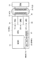
図1は、本発明の実施の形態の非接触電子モジュールの衝突防止方法を実施する非接触電子モジュール(図中、「MDL」と示される。)10のブロック図である。図1に示すように、本発明の実施の形態の非接触電子モジュール10は、本質的には典型的である一般的な構造を有し、中央処理装置(図中、「CPU」と示される。)11と、例として、EPROM(Erasable Programmable Read Only−Memory)やEEPROM(Electrically Erasable and Programmable Read Only−Memory)などの不揮発性タイプのメモリ領域(図中、「MEM1」と示される。)13と、揮発性メモリ(図中、「MEM2」と示される。)15と、アンテナコイル(図中、「ACL」と示される。)17とを備えている。
【0045】
尚、アンテナコイル17は、通信インタフェースを構成する。
【0046】
非接触電子モジュール10が、端末(図中、「TRM」と示される。)19から送信される、交流磁界21内に置かれた時、交流電圧Viが、アンテナコイル17の端子に発生し、この電圧Viは、磁界の搬送周波数で振動する。
【0047】
不揮発性メモリ領域13は、例えば、それぞれ32ビットからなる128のブロックを備えている。揮発性メモリ領域15は、CPU11によって使用される典型的な種々のレジスタを備えているが、図1には、全ては示されていない。例えば、揮発性メモリ領域15は、非接触電子モジュール10の識別番号を含むレジスタIDREG23を備え、このレジスタIDREG23は、2つの部分ID1およびID2を有する。
【0048】
例えば、ID1部は、識別番号の最上位ビットを含み、ID2部は、識別番号の最下位ビットを含む。本実施の形態において、ID1部およびID2部は、それぞれ4ビットを有するが、これに限定されるものではない。以下に説明される識別番号は、16進法で表記され、識別番号は、例えば、00(8ビット全て0)からFF(8ビット全て1、すなわち、10進法で256)の範囲を取り得るものとする。
【0049】
本発明によれば、レジスタIDREG23は、乱数発生器(図中、「RGEN」と示される。)27の出力に連結される。本実施の形態において、この乱数発生器27は、4ビットの乱数発生器であるので、簡単に実現でき、これは小さいシリコン表面を占有する。乱数発生器27は、CPU11によって使用され、通信の前に、ランダムな識別番号のID1部およびID2部を生成する。非接触電子モジュール10が、磁界21によってアクティブにされた時、識別番号が生成され、後述されるレディ状態に切り替わる。
【0050】
さらに、CPU11は、乱数発生器27を使用して、後述されるコマンドPCALL16に相当する汎用または補足識別要求に応答しなければならない場合に、識別番号の新たなID2部を生成する。本発明によれば、CPU11は、このような識別要求に呼応して、識別番号のID2部に等しいタイムスロットを選択する。
【0051】
非接触電子モジュール10の通信インタフェースは、電源回路(図中、「PSC」と示される。)31と、復調器(図中、「DMD」と示される。)33と、変調器(図中、「LMD」と示される。)35とを備えている。電源回路31は、非接触電子モジュール10の供給電圧Vccを引き渡すものであり、これは、誘導電圧Viを整流することによって得られる。復調器33は、誘導電圧Viから端末19によって送信されたデータDTRを抽出するものである。これらのデータは、一般的に、磁界の振幅を変調することによって送信され、例えば、ASKコード化(Amplitude Shift Keying Modulation)される。
【0052】
変調器35は、アンテナコイルの電荷変調の原理によってデータDTxを送信するものである。データDTxは、例えば、磁界の搬送波から抽出されたサブ搬送波によってBPSKコード化(Phase Shift Keying Modulation)される。搬送波は、例えば、13.56MHzであり、サブ搬送波は、847KHzである。この場合、得られるデータの流れは、100Kbit/秒のオーダーである。
【0053】
CPU11は、マイクロプロセッサ、またはハードワイヤードロジックタイプ(シーケンサなど)のものであり、本発明に係る衝突防止方法に特有のステップや命令を実行するだけでなく、端末19から送信されたメッセージ(謂わば、コマンド)を解読して処理し、端末19にメッセージ(謂わば、応答)を送信するものである。
【0054】
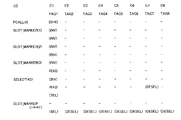
図2は、非接触電子モジュール10の動作を示す状態図である。6つの状態、電源オフ状態(図中、「POWER−OFF」と示される。)S1、レディ状態(図中、「READY」と示される。)S2、インベントリ状態(図中、「INVENTORY」と示される。)S3、選択状態(図中、「SELECTED」と示される。)S4、非活動化状態(図中、「DEACTIVATED」と示される。)S5、および非選択状態(図中、「DESELECTED」と示される。)S6がそれぞれ示されており、端末19から送信されるコマンド、「PCALL0」、「PCALL16」、「SLOT_MARKER(i)」、「SELECT(ID)」、「SELECT(NONID)」、「DEACTIVATE」、「READ_BLOCK」、および「WRITE_BLOCK」も示されている。
【0055】
これらのコマンド、並びにこれらに対する非接触電子モジュール10から送信された応答、例えば、「R(ID)」、および「R_READ_BLOCK」については、本実施の形態の末尾により詳細に説明してあるので参照のこと。
【0056】
非接触電子モジュール10の各状態間の遷移は、以下に説明する「OF」および「OOF」で示されるイベントによっても決定される。
【0057】
イベントOFは、磁界内(On Field)を示し、非接触電子モジュール10が磁界21の誘導境界内に入った場合に相当する。そして非接触電子モジュール10は、電源オフ状態S1からレディ状態S2になり、交流電圧Viが、アンテナコイルの端子に発生した時、電源回路31が、電圧Vccを引き渡す。
【0058】
イベントOFFは、磁界外(Out Of Field)を示し、非接触電子モジュール10が、端末19から送信された磁界の誘導境界から離れた場合に相当する。非接触電子モジュール10は、アクティブであるか、レディ状態S2、インベントリ状態S3、選択状態S4、非選択状態S5、または非活動化状態S6の何れか一つであった場合、誘導電圧Viの消失(あるいは、不十分な値)によって、電源回路31からの電気的な供給がなくなる。そして、非接触電子モジュール10は、電源オフ状態S1に戻る。
【0059】
以下、図2の各状態について詳細に説明する。
【0060】
レディ状態S2
非接触電子モジュール10が、レディ状態S2に切り替わると、ランダムな識別番号を生成し、インベントリ状態S3に切り替わるコマンドPCALL0またはPCALL16を待つ。ここで、コマンドPCALL0は、衝突防止コマンドとしてではなく、非接触電子モジュール10全てを同時に識別しなければならないものとして、本発明の骨子の範囲内で任意である。このコマンドは、一つの非接触電子モジュール10が存在する場合に、衝突防止処理のトリガとならないようにするものである。従って、他の実施の形態において、レディ状態S2からインベントリ状態S3への遷移は、コマンドPCALL16を受信することにのみ連結され得るものである。逆に言えば、レディ状態S2からインベントリ状態S3への遷移への準備は、コマンドPCALL0を受信することに排他的に連結されるべきである。この場合、衝突のイベントにおいて、衝突防止処理はインベントリ状態S3の時に単にトリガとなる。
【0061】
インベントリ状態S3
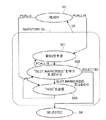
非接触電子モジュール10が、インベントリ状態S3に切り替わった時、図3に示されるフローチャートに示される幾つかの動作が実行される。インベントリ状態S3への切替えが、コマンドPCALL0を受信したことによって引き起こされた場合、非接触電子モジュール10は、直接ステップS33に進み、自分の識別番号を有する応答R(ID)の形式をとる識別メッセージを送信する。ステップS33の後、非接触電子モジュール10はステップS32に進む。インベントリ状態S3への切替えが、コマンドPCALL16を受信したことによって引き起こされた場合は、非接触電子モジュール10は、直接ステップS31に進み、乱数発生器27によって自分の識別番号の新たなID2部を生成する。そして非接触電子モジュール10は、ステップS32に進む。
【0062】
ステップS32では、非接触電子モジュール10は、i=ID2を有するマーキングコマンドSLOT_MARKER(i)を待つ。すなわち、コマンドSLOT_MARKER(ID2)であり、これは、非接触電子モジュール10の識別番号のID2部に対応するタイムスロットを示している。コマンドSLOT_MARKER(ID2)が受信された時、非接触電子モジュール10は、ステップS33に進み、応答R(ID)を送信し、そしてステップS32に戻る。
【0063】
本実施の形態において、コマンドPCALL16は、第1のタイムスロットのマーキングコマンドを形成しているので、非接触電子モジュール10は、自分の識別番号のID2部が0であった場合は、ID2部が第1のタイムスロットに相当するので、ステップS32から直接ステップS33に進む。
【0064】
ステップS32は、さらに選択待ちのステップでもあり、非接触電子モジュール10は、自分の識別番号を含むコマンドSELECT(ID)が受信されるまで、そのままそこに残る(あるいは、復帰する)。このコマンドを受信した時、非接触電子モジュール10は、選択状態S4に切り替わる。
【0065】
非接触電子モジュール10は、さらにステップS32にある時に、新たなコマンドPCALL16を受信できる。この場合、非接触電子モジュール10は、ステップS31に戻り、自分の識別番号の新たなID2部を生成し、そしてステップS32に復帰する。
【0066】
選択状態S4
ひとたび、選択状態S4に入ると、非接触電子モジュール10は、もはや、即時識別要求PCALL0に応答することも、あるいは、汎用または補足識別要求PCALL16に応答することもない。非接触電子モジュール10の不揮発性メモリ領域13は、コマンドREAD_BLOCKまたはWRITE_BLOCKによって端末19により読み出し、または書き込みがなされる。コマンドREAD_BLOCKに呼応して、端末19は、応答R_READ_BLOCKを受信する。非接触電子モジュール10が、コマンドSELECT(NONID)を受信した場合、すなわち、自分のではない識別番号を含むコマンドSELECT(ID)を受信した場合、非接触電子モジュール10は、非選択状態S5に切り替わる。非接触電子モジュール10が、コマンドDEACTIVATEを受信した場合は、非活動化状態S6に切り替わる。
【0067】
非選択状態S5
非選択状態S5にある非接触電子モジュール10は、自分の識別番号を含むコマンドSELECT(ID)以外のどのコマンドにも応答しない。また、非選択状態S5にある非接触電子モジュール10は、このコマンドにより、選択状態S4に復帰させられる。また、磁界の消失(イベントOOF)により、電源オフ状態S1に戻る。
【0068】
非活動化状態S6
非活動化状態S6にある非接触電子モジュール10は、どのコマンドにも応答しない。磁界の消失(イベントOOF)によってのみ、電源オフ状態S1に戻る。
【0069】
衝突防止シーケンスの例
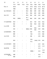
本発明に係る衝突防止シーケンスの例は、図4乃至図7に示される。本発明の実施の形態において、TAG1乃至TAG8で記される8つの非接触電子モジュール10が、端末19の問合せフィールドに同時に入るものとする。C0列には、端末19から送信されるコマンドが記載される。C1〜C8列には、非接触電子モジュール10から送信される応答と、非接触電子モジュール10によって生成される識別番号と、非接触電子モジュール10の状態とが記載される。図中、電源オフ状態S1は、「P−O」と記され、レディ状態S2は、「RDY」と記され、インベントリ状態S3は、「INV」と記され、選択状態S4は、「SEL」と記され、非選択状態S5は、「DESEL」と記される。
【0070】
本シーケンスの開始は、図4に記載される。全ての非接触電子モジュール10が、電源オフ状態S1にあり、各非接触電子モジュール10は、不特定の識別番号(「xx」)が、レジスタIDREG23に含まれる。磁界が出現した時(イベントOF)、複数の非接触電子モジュール10は、レディ状態S2に切り替わり、それぞれ識別番号を生成する。本実施の形態においては、TAG1〜TAG8の非接触電子モジュール10の識別番号はそれぞれ、40、13、3F、4A、50、48、52、7Cである。
【0071】
一つでも非接触電子モジュール10が端末19の問合せフィールド内に位置した場合には、端末19は、即時識別要求PCALL0を送信する。複数の非接触電子モジュール10は、インベントリ状態S3に切り替わり、同時に、自分の識別番号を含むメッセージR(ID)、すなわち、TAG1〜TAG8の非接触電子モジュール10はそれぞれ、R(40)、R(13)、R(3F)、R(4A)、R(50)、R(48)、R(52)、R(7C)により応答する。これらの応答は、全て衝突し、端末19によって読み取ることができない。その後、端末19は、汎用識別要求PCALL16を送信する。各非接触電子モジュール10は、ID1部を保持しながら、自分の識別番号の新たなID2部を計算する。本実施の形態においては、TAG1〜TAG8の非接触電子モジュール10の識別番号はそれぞれ、45、12、30、43、55、43、53、73となる。
【0072】
コマンドPCALL16は後述するように、第1タイムスロットのマーキングコマンドを形成すると規定されているので、識別番号のID2部が0に等しく、かつ第1タイムスロットに相当するTAG3の非接触電子モジュール10は、メッセージR(30)を送信することによって、コマンドPCALL16に応答する。この非接触電子モジュール10からの応答が他の応答と衝突しないので、端末19は、これを読み取ることができ、選択コマンドSELECT(30)を送り返すことができる。非接触電子モジュール10は、これに応答してメッセージR(ID)、すなわちR(30)を再び送信する。そして、TAG3の非接触電子モジュール10は、選択状態S4に切り替わる。
【0073】
そして、端末19は、コマンドSLOT_MARKER(1)を送信し、どの非接触電子モジュール10もこれに応答しないので、コマンドSLOT_MARKER(2)を送信する。このコマンドに対して、TAG2の非接触電子モジュール10が、自分の識別番号のID2部が2に等しいと識別すると同時に、応答する。
【0074】
既に記載した手順に従って、TAG2の非接触電子モジュール10が選択され、その結果、既に選択されているTAG3の非接触電子モジュール10が非選択状態S5に自動的に切り替わる(図2のコマンドSELECT(NONID)参照)。そして端末19は、iが3からFの範囲でコマンドSLOT_MARKER(i)を順に送信し続ける。
【0075】
コマンドSLOT_MARKER(3)が送信された時、TAG4、TAG6、TAG7およびTAG8の非接触電子モジュール10が、同時に応答するため、端末19は、何れも選択できない。また、TAG1およびTAG5の非接触電子モジュール10は、同時にコマンドSLOT_MARKER(4)に応答するため、これらもまた選択できない。続く6からFのタイムスロットにおいては、何れの非接触電子モジュール10も応答しない。
【0076】
従って、図4に示される第1の衝突防止サブシーケンスが終了した時点では、TAG2およびTAG3の非接触電子モジュール10のみが選択されたことになり、TAG3の非接触電子モジュール10は非選択状態S5にあり、TAG2の非接触電子モジュール10は、選択状態S4にある。
【0077】
次に、新たな第2の衝突防止シーケンスが図5に示されており、これは、端末19がコマンドPCALL16を送信することによって引き起こされ、まだ選択待ちをしている非接触電子モジュール10のために補足識別要求を続ける。そして、コマンドPCALL16に呼応して、非接触電子モジュール10は、自分の識別番号の新たなID2部を生成し、例えば、TAG1は40、TAG4は41、TAG5は53、TAG6は42、TAG7は50、TAG8は74となる。TAG1およびTAG7の非接触電子モジュール10は、第1タイムスロットで同時に応答するので、選択されない。TAG4の非接触電子モジュール10が、コマンドSLOT_MARKER(1)によってマークされる第2タイムスロットにおいて選択され、さらにTAG6の非接触電子モジュール10が、コマンドSLOT_MARKER(2)によってマークされる第3タイムスロットにおいて選択される。また、TAG5の非接触電子モジュール10が、コマンドSLOT_MARKER(3)によってマークされる第4タイムスロットにおいて選択される。さらに、TAG8の非接触電子モジュール10が、コマンドSLOT_MARKER(4)によってマークされる第5タイムスロットにおいて選択される。iが5からFに進む間、後のタイムスロットにおいて応答する非接触電子モジュール10は無い。
【0078】
従って、図5に示される第2の衝突防止シーケンスが終了した時点では、TAG1およびTAG7以外の全ての非接触電子モジュール10が選択済みとなり、TAG8の非接触電子モジュール10は選択状態S4で、TAG2〜TAG6の非接触電子モジュール10は非選択状態S5に切り替わっている。
【0079】
図6に示される第3の衝突防止シーケンスは、コマンドPCALL16を送信することによって引き起こされる。TAG1の非接触電子モジュール10は、41に等しい識別番号を生成し、TAG7の非接触電子モジュール10は、50に等しい識別番号を生成する。このとき、上述されるように、ID1部は保持されたままである。TAG7の非接触電子モジュール10は、コマンドPCALL16によってマークされる第1タイムスロットにおいて選択される。TAG1の非接触電子モジュール10が、選択されていない唯一のモジュールであるので、コマンドSLOT_MARKER(1)によってマークされる第2タイムスロットにおいて応答して、メッセージR(41)を送信する。しかしながら、他の非接触電子モジュール10、すなわち、図5の第2の衝突防止サブシーケンスの間に既に選択されているTAG4の非接触電子モジュール10によって、既に識別番号41は選択されているので、端末19は、TAG1の非接触電子モジュール10を選択することは無い。従って、端末19は、コマンドSELECT(41)を送信せず、他の非接触電子モジュール10が問合せフィールド内に入って来た場合には、iがFになるまで、残りのタイムスロットをマークし続ける。
【0080】
図7に示される第4の衝突防止シーケンスは、コマンドPCALL16を送信することによって引き起こされる。TAG1の非接触電子モジュール10は、他の非接触電子モジュール10の何れによっても使用されていない識別番号43を選択する。これにより、TAG1の非接触電子モジュール10がコマンドSLOT_MARKER(3)によってマークされた第4のタイムスロットにおいて選択される。さらに他の非接触電子モジュール10が問合せフィールド内にある場合に、端末19は、残りのタイムスロットをマークし続ける。
【0081】
以上説明してきた衝突防止シーケンスは、一実施の形態であり、他の実施の形態の衝突防止シーケンスも可能であることは明白である。
【0082】
このように、例えば、TAG3の非接触電子モジュール10が、図5に示される第1衝突防止サブシーケンスの間に選択された時、端末19は、残りのタイムスロットでのマーキングコマンドの送信を止めても良く、そして端末19は、TAG3の非接触電子モジュール10と通信を確立し、データを読み書きし、そして非接触電子モジュール10を非活動化状態S6に切替えさせることも可能である。
【0083】
あるいは、端末19は、TAG3の非接触電子モジュール10との会話の後、選択状態S4を解除し、衝突防止シーケンスを続けることもできる。この場合、端末19がコマンドSELECT(12)を送信して、TAG2の非接触電子モジュール10を選択した時、TAG3の非接触電子モジュール10にとって、このコマンドはSELECT(NONID)であるので、TAG3の非接触電子モジュール10は非選択状態S5に自動的に切り替わる。上記の非活動化状態S6との違いは、その後、端末19がコマンドSELECT(30)を送信することによって、TAG3の非接触電子モジュール10を選択する可能性を維持していることである。
【0084】
他の実施の形態によれば、端末19は、マーキングコマンドをあらゆる順序、または決められた順序で、送信しても良い。このようにマーキングコマンドが制御下にある場合、タイムスロットを昇順で端末19に強制的にマークさせることはない。
【0085】
また、本実施の形態においては、汎用または補足識別要求PCALL16が、第1タイムスロットをマークするのに使用されているが、これに限らず、第1タイムスロットをマークするコマンドSLOT_MARKER(0)を設けても良い。
【0086】
さらに、非接触電子モジュール10の識別番号のID1部は、ランダムにせずに、不揮発性メモリ領域13内に記録しておくことも可能である。
【0087】
また、ID1部は、タイムスロットを決定するのに使用されるID2部よりも長くしても良い。
【0088】
逆に、タイムスロットは、識別番号全部を使用して決定することもできる。この場合、コマンドPCALL16に呼応した新たな識別番号の生成は、識別番号全体であっても良いし、識別番号の一部のみであっても良い。
【0089】
上述されるように、本発明は、誘導型非接触モジュールの生産の骨子の範疇であるが、本発明に係る方法は、他の様々なタイプの非接触モジュールに適用可能であり、特に、磁界の代わりに電界を送信する端末とUHF(Ultra High Frequency)帯域内で会話するものであっても良い。
【0090】
<端末から送信される主なコマンドおよび非接触電子モジュールから返信される主な応答>
定義、省略記号の説明:
−コマンド:端末19から送信されるメッセージ。
−応答:非接触電子モジュール10から送信されるメッセージ。
−SOF:フレームフィールドの開始部。
−EOF:フレームフィールドの終端部。
−CODE(コマンド):コマンドまたは応答のコード。4、8または16ビットで、コマンドまたは応答のフィールド内に存在する。
−CRC1およびCRCh:コマンドまたは応答に付随するCRCタイプのシグネチャの最上位ビットおよび最下位ビットであり、受信先に、伝送エラーを検出させ、特に、端末19に、応答R(ID)間での衝突を検出させる。
【0091】
コマンド:
<コマンドPCALL0>
説明:
非指名の即時識別要求。
このコマンドを実行する非接触電子モジュール10:
レディ状態S2またはインベントリ状態S3にある非接触電子モジュール10(すなわち選択されていない非接触電子モジュール10)。
このコマンドへの応答:
複数の非接触電子モジュール10がそれぞれ直ぐに識別メッセージR(ID)を送信する。
各状態における非接触電子モジュール10のこのコマンドの効果:
レディ状態S2にある非接触電子モジュール10は、インベントリ状態S3に切り替り、インベントリ状態S3にある非接触電子モジュール10は、インベントリ状態S3のままとなる。
【表1】

<コマンドPCALL16>
説明:
非指名型の汎用識別要求または非指名型の補足識別要求であり、第1タイムスロット(i=0)のマーキングコマンドを任意に形成する。
このコマンドを実行する非接触電子モジュール10:
レディ状態S2またはインベントリ状態S3にある非接触電子モジュール10(すなわち選択されていない非接触電子モジュール10)。
このコマンドへの応答:
コマンドPCALL16が、第1タイムスロットのマーキングコマンドとして使用された場合、識別番号=0を有する非接触電子モジュール10が、識別メッセージR(ID)を送り返す。
各状態における非接触電子モジュール10のこのコマンドの効果:
レディ状態S2にある非接触電子モジュール10は、インベントリ状態S3に切り替わり、インベントリ状態S3にある非接触電子モジュール10は、インベントリ状態S3のままとなる。
【表2】
<コマンドSLOT_MARKER(i)>
説明:
第i番目のタイムスロットのマーキングコマンド。iはコマンド内で指定され、かつi>0(i=0の場合は、コマンドPCALL16を参照)。
このコマンドを実行する非接触電子モジュール10:
インベントリ状態S3にある非接触電子モジュール10。
このコマンドへの応答:
非接触電子モジュール10の識別番号のID2部とiが等しい場合、非接触電子モジュール10が識別メッセージR(ID)を送信する。
各状態における非接触電子モジュール10のこのコマンドの効果:
インベントリ状態S3にある非接触電子モジュール10は、自分の識別番号を含む選択コマンドSELECT(ID)を受信しない間は、インベントリ状態S3のままである。
【表3】
<コマンドSELECT(ID)>
説明:
非接触電子モジュール10を選択するためのコマンドであり、その識別番号が、コマンド内に指定される(指名コマンド)。
このコマンドを実行する非接触電子モジュール10:
インベントリ状態S3または非選択状態S5にある非接触電子モジュール10。
このコマンドへの応答:
識別番号によって指定された非接触電子モジュール10が、確認の目的で、識別メッセージR(ID)を送信する。
各状態における非接触電子モジュール10のこのコマンドの効果:
インベントリ状態S3にある非接触電子モジュール10が、選択状態S4に切り替わり、非選択状態S5にある非接触電子モジュール10が、選択状態S4に戻る。
【表4】
<コマンドSELECT(NONID)>
説明:
受信された選択コマンド(コマンドSELECT(ID))が、非接触電子モジュール10の識別番号に相当しない識別番号を含む場合。
このコマンドを実行する非接触電子モジュール10:
選択状態S4にある非接触電子モジュール10。
このコマンドへの応答:
無し。
各状態における非接触電子モジュール10のこのコマンドの効果:
選択状態S4にある非接触電子モジュール10が、非選択状態S5に切り替わる。
【0096】
<コマンドDEACTIVATE>
説明:
選択状態S4にある非接触電子モジュール10を非活動化するコマンド(非指名コマンド)。
このコマンドを実行する非接触電子モジュール10:
選択状態S4にある非接触電子モジュール10。
このコマンドへの応答:
無し。
各状態における非接触電子モジュール10のこのコマンドの効果:
選択状態S4にある非接触電子モジュール10が、非活動化状態S6に切り替わる。
【表5】
<コマンドRESET_TO_INVENTORY>
説明:
選択状態S4にある非接触電子モジュール10を、インベントリ状態S3に戻すためのコマンド(非指名コマンド)。
このコマンドを実行する非接触電子モジュール10:
選択状態S4にある非接触電子モジュール10。
このコマンドへの応答:
無し。
各状態における非接触電子モジュール10のこのコマンドの効果:
選択状態S4にある非接触電子モジュール10が、インベントリ状態S3に戻る。
【表6】
<コマンドREAD_BLOCK>
説明:
不揮発性メモリ領域13内のNビットのブロックを読み出すためのコマンドであり、コマンド(ADDRESSフィールド)内に、アドレスが指定される。
このコマンドを実行する非接触電子モジュール10:
選択状態S4にある非接触電子モジュール10。
このコマンドへの応答:
応答R_READ_BLOCK(下記参照)。
各状態における非接触電子モジュール10のこのコマンドの効果:
無し。
【表7】
<コマンドWRITE_BLOCK>
説明:
不揮発性メモリ領域13内のNビットのブロック(DATA1〜DATA4フィールド)を書き込むためのコマンドであり、コマンド(ADDRESSフィールド)内に、アドレスが指定される。
このコマンドを実行する非接触電子モジュール10:
選択状態S4にある非接触電子モジュール10のみ。
このコマンドへの応答:
無し(ただし、コマンドREAD_BLOCKによって端末19により書き込み検査が行われる)。
各状態における非接触電子モジュール10のこのコマンドの効果:
無し。
【表8】
応答:
<応答R(ID)>
説明:
コマンドPCALL0、PCALL16、SLOT_MARKER、またはSELECT(ID)に対する非接触電子モジュール10の応答。この応答は、非接触電子モジュール10の識別番号を含む。
【表9】
<応答R_READ_BLOCK>
説明:
コマンドREAD_BLOCKに対する非接触電子モジュール10の応答であり、読み出される不揮発性メモリ領域13内のNビットのブロック(DATA1〜DATA4フィールド)を含み、コマンド内に、そのアドレスが指定される。
【表10】
以上説明したように、本発明は、端末と複数の非接触電子モジュールとの間の通信に先立って、各非接触電子モジュールがランダムな識別番号を生成し、前記端末が、汎用識別要求を送信して、前記複数の非接触電子モジュールからの識別メッセージの送信を誘発し、前記複数の識別メッセージが衝突した時、少なくとも一つの非指名の補足識別要求を送信し、前記非接触電子モジュールの識別番号を含む選択メッセージを受け取った時、一つの非接触電子モジュールが選択され、タイムスケール上で所定のタイムスロットに到達した時、前記汎用または補足識別要求に呼応して、選択されていない非接触電子モジュールがその識別番号を含む識別メッセージを送信し、前記一つの端末によって複数の非接触電子モジュールを識別し、選択する衝突防止方法であって、前記非接触電子モジュールが、その識別番号に応じて変化するタイムスロットの時に、汎用または補足識別要求に応答し、前記補足識別要求を受信した時、選択されていない非接触電子モジュールが、新たなランダムな識別番号を生成し、その識別番号に応じてタイムスロットが変化する間、前記補足識別要求に呼応した選択されていない非接触電子モジュールのタイムスロットが、前回の補足識別要求に呼応した非接触電子モジュールのタイムスロットと統計的に同じにならないようにすることにより、複数の非接触電子モジュールの識別工程がツリー構造ではないので、実行するのが簡単で、処理が早く、また識別番号も短くできるので、高性能な乱数発生器も不要であり、また、無駄な識別処理を行わないので、より処理が早くなるという優れた効果を有する非接触電子モジュールの衝突防止方法を提供することができるものである。
【図面の簡単な説明】
【図1】本発明の実施の形態の非接触電子モジュールのブロック図
【図2】図1に示す非接触電子モジュールの動作を示す状態図
【図3】図2に示すインベントリ状態における図1に示す非接触電子モジュールの動作を示すフローチャート図
【図4】本発明の実施の形態の非接触電子モジュールの衝突防止シーケンスを示す図
【図5】本発明の実施の形態の非接触電子モジュールの衝突防止シーケンスを示す図
【図6】本発明の実施の形態の非接触電子モジュールの衝突防止シーケンスを示す図
【図7】本発明の実施の形態の非接触電子モジュールの衝突防止シーケンスを示す図
【図8】従来の非接触通信方法における端末の問合せフィールド内に同時に存在する複数の非接触モジュールの配置図
【符号の説明】
10 非接触電子モジュール
11 CPU
13 不揮発性メモリ領域
15 揮発性メモリ領域
17 アンテナコイル
19 端末
21 磁界
23 レジスタIDREG
27 乱数発生器
31 電源回路
33 復調器
35 変調器
ID1 識別番号の一部(第1の部分)
ID2 識別番号の一部(所定の部分、第2の部分)
PCALL0 即時識別要求
PCALL16 汎用識別要求、補足識別要求
SLOT_MARKER(i) マーキングコマンド
SELECT(ID) 選択コマンド(選択メッセージ)
R(ID) 応答(識別メッセージ)[0001]
TECHNICAL FIELD OF THE INVENTION
The present invention relates to non-contact data communication technology, and more particularly to non-contact data communication technology by electromagnetic induction applied to non-contact electronic tags, non-contact smart cards, and other equivalent portable non-contact electronic objects. It is. In addition, the present invention particularly relates to a collision prevention method for identifying a non-contact electronic module by a terminal.
[0002]
[Prior art]
Conventionally, in the application of this type of contactless data communication technology, it is often the case that a plurality of contactless electronic modules are simultaneously located in the inquiry field of the terminal. For example, this situation is shown in FIG. 8, in which one terminal 1 (indicated as “TRM” in the figure) communicates with this
[0003]
The plurality of non-contact electronic modules 3 (M1 to Mn) each include a communication interface 9 (indicated as “IM” in the drawing) having an antenna coil, and generally perform charge modulation (magnetic field caused by short-circuiting the antenna coil). ), Data can be transmitted to
[0004]
Very simple identification without, for example, financial transactions, identification and authentication operations to issue tolls (access control), operation of toll barriers or, for example, authentication (inventory) of existing contactless
[0005]
Generally speaking, the
[0006]
This problem is solved using an anti-collision method. First, each contactless
[0007]
According to the known anti-collision methods, there are deterministic methods and established methods, which are distinguished.
[0008]
According to the deterministic method, the terminalNA marking command indicating a time slot (response position) on a time scale (temporary response scale) having a time slot of? Each contactless electronic module transmits an identification message including its own identification number when it reaches a time slot corresponding to the first N bits of its own identification number. If only one contactless electronic module responds in a time slot, the terminal can identify and select that contactless electronic module.
[0009]
If two contactless electronic modules respond in the same time slot, then the first N bits of their identification numbers are the same. The terminal detects the collision and transmits a nomination supplementary identification request including the N bits of the conflicting identification number. This nomination supplement identification request is only relevant for the contactless electronic module colliding in the time slot defined by the specified N bits. In response to the nomination supplementary identification request, the plurality of contactless electronic modules establish a new time slot using the next N bits of their identification numbers, and transmit a new identification message. This sequence can be repeated several times until all contactless electronic modules have been identified and / or selected, and for each time slot the same as the number of remaining subgroups for every N bits in the identification number It can be repeated the number of times.
[0010]
The identification process has a tree structure, with each nominated supplemental identification step only relevant to the contacting electronic module colliding at a given time slot. Thus, for example, the first two contactless electronic modules have the same first N bits and are different from the first N bits of the first two contactless electronic modules, but another two contactless electronic modules , Having the same first bit as each other, the identification of the four contactless electronic modules requires at least two supplemental identification steps, one being a choice between the first two contactless electronic modules and the other being The choice between the other two contactless electronic modules.
[0011]
The probabilistic method can be distinguished from the deterministic method, wherein the time slot of the contactless electronic module has no relation to its own identification number. The terminal first sends a universal identification request, which causes the contactless electronic module to generate a random number. This random number determines the time slot of the contactless electronic module and sends an identification message containing its identification number. The effectiveness of the probabilistic method is that when the number of contactless electronic modules increases, regardless of the length of the identification number (the need to not include two contactless electronic modules with the same identification number still remains However, it depends on the variation of the time scale. Thus, the greater the number of time slots, the greater the effectiveness of the stochastic method. In the event of a collision, the unidentified contactless electronic module receives the unassigned supplemental identification request and determines a new random time slot. Since this supplemental identification step is not a nomination, it involves a contactless electronic module that collides at a different time slot and differs from the deterministic method of the nomination identification step.
[0012]
[Patent Document 1]
JP 2001-92930 A
[0013]
[Problems to be solved by the invention]
However, in such a conventional deterministic collision prevention method, the number of the non-contact electronic modules is very complicated because of the tree structure, and the identification of each non-contact electronic module is very complicated. There is a problem that a longer processing time is required.
[0014]
Furthermore, this anti-collision method means that the contactless electronic module executes a relatively complex algorithm that can know whether to respond to the nomination supplement identification request.
[0015]
In addition, when the number of contactless electronic modules increases, the risk that two contactless electronic modules have the same identification number also increases, which means that a complete collision and the inability to choose between the two contactless electronic modules Matches. Therefore, the length of the identification number must be increased to reduce this risk. In addition to providing this very long identification number, another measure that can reduce the risk of a complete collision is that each contactless electronic module generates a random identification number prior to communication. is there. The identification number is then used by the contactless electronic module during all successive interrogations until the contactless electronic module is powered off or deactivated. However, the generation of very long random identification numbers requires the provision of powerful and powerful multiple random number generators, which are very cumbersome, very expensive and, in terms of silicon surfaces, very expensive. There is a problem that the size becomes large.
[0016]
A deterministic anti-collision method is recommended, for example, by the standard ISO 14443-3 type B, which specifies that the contactless electronic module has a randomizable 32-bit identification number.
[0017]
In summary, conventional deterministic methods must provide tree-type identification of contactless electronic modules, which is complex, slower to implement, and requires multiple sophisticated random number generators. There was a problem of doing.
[0018]
However, there is also an advantage of these methods, since the identification of the contactless electronic modules is of a tree type, the selection of the actual number of time slots is not mandatory. For example, by selecting N = 4 (ie, 4 bits), only 16 time slots are obtained.
[0019]
On the other hand, the conventional stochastic collision avoidance method is simpler to implement as far as the algorithms loaded in the relevant contactless electronic modules are concerned, but the widespread applicable to the actual few minutes of contactless electronic modules There is a problem that a special time scale is required. In other words, if the time scale is extensive, the identification process may be unnecessarily long even when a small number of contactless electronic modules are simultaneously located in the terminal's interrogation field. It would be conceivable that 255 time slots were provided and only two contactless electronic modules were located in the terminal's interrogation field. One of the contactless electronic modules has a slot no. 1 can be selected at random, and the other non-contact electronic module has a slot no. 255 can be selected. In this case, after the identification of the first non-contact electronic module, it is necessary to identify the second non-contact electronic module until the 255th time slot is reached over the entire time scale.
[0020]
A further disadvantage of this classical stochastic method is that collisions of identification numbers can occur between two contactless electronic modules that do not respond in the same time slot. The terminal must then request the contactless electronic module to generate a new identification number, and start the identification process again.
[0021]
The present invention has been made to solve such a problem, and an object of the present invention is to provide a method for preventing collision of a non-contact electronic module which does not have a disadvantage of a known method, and a non-contact electronic module thereof.
[0022]
To this end, the general idea of the invention provides for a combination of means using both deterministic and stochastic methods. According to the invention, the identification request sent from the terminal is not nominated, as in the case of the stochastic method, but the time slot of the contactless electronic module is the same as in the deterministic method. , According to the identification number of the non-contact electronic module. In addition, when the contactless electronic module responds to the supplemental identification request, it randomly generates a new identification number, so that the time slots are random and not fixed, as in the stochastic method. The identification process is therefore not tree-shaped and easier to perform. Preferably, the time slot should only depend on a part of the identification number, as in the deterministic method, so that the part of the identification number used to determine the time slot is a small bit If it includes numbers, the time scale may have a small number of time slots.
[0023]
[Means for Solving the Problems]
In the method for preventing collision of a non-contact electronic module according to the present invention, prior to communication between a terminal and a plurality of non-contact electronic modules, each of the non-contact electronic modules generates a random identification number, and the terminal performs general-purpose identification. Sending a request to trigger transmission of an identification message from the plurality of contactless electronic modules; and transmitting at least one non-nominated supplemental identification request when the plurality of identification messages collide, Upon receiving the selection message including the identification number of the module, one contactless electronic module is selected, and upon reaching a predetermined time slot on the time scale, in response to the general or supplementary identification request, one of the contactless electronic modules is selected. No contactless electronic module sends an identification message including its identification number, and the plurality of contactless electronic modules by the one terminal An anti-collision method for identifying and selecting, wherein the contactless electronic module responds to a general or supplemental identification request at a time slot that changes according to its identification number, and receives the supplemental identification request. The unselected contactless electronic module generates a new random identification number, and the time of the unselected contactless electronic module in response to the supplementary identification request while the time slot changes according to the identification number. It is characterized in that the slot is not statistically the same as the time slot of the contactless electronic module in response to the previous supplementary identification request.
[0024]
As a result, the identification process of the plurality of non-contact electronic modules is not a tree structure, is easy to execute, is quick, and the identification number can be shortened, so that a high-performance random number generator is not required. Since the useless identification processing is not performed, the processing becomes faster.
[0025]
In the method for preventing collision of a non-contact electronic module according to the present invention, the general-purpose identification request may have the same format and code as the supplemental identification request.
[0026]
Further, in the collision prevention method for a non-contact electronic module according to the present invention, the non-contact electronic module determines a time slot equal to a predetermined portion of its own identification number, and the non-contact electronic module responds to a continuous identification request. In this case, the predetermined portion of the identification number may include a bit at a predetermined position that does not change. Further, the predetermined part of the identification number of the non-contact electronic module may include a least significant bit of the identification number.
[0027]
In the method for preventing collision of a non-contact electronic module according to the present invention, a new random identification number is generated, and the non-contact electronic module holds a first part of a current identification number, and The
[0028]
Further, in the method for preventing collision of a non-contact electronic module according to the present invention, when an identification message from the non-contact electronic module in response to a previously transmitted supplementary identification request is received, the identification message may collide with another identification message. If not, and includes an identification number already used by another contactless electronic module, the terminal may further transmit the supplemental identification request.
[0029]
In the method for preventing collision of a non-contact electronic module according to the present invention, when the non-contact electronic module is in a magnetic field transmitted from a terminal, it is automatically activated, and when activated, a random identification is performed. A number may be generated.
[0030]
In the method for preventing collision of a non-contact electronic module according to the present invention, the plurality of time slots on the time scale may be marked by a marking command transmitted from the terminal.
[0031]
Further, in the method for preventing collision of a non-contact electronic module according to the present invention, the universal identification request may form a marking command of a first time slot of the time scale. Further, the marking command may include a time slot number, and may be a plurality of time slots equal to or more than a first time slot. Further, the terminal may transmit the marking commands in an order that does not correspond to the ascending order of the time slots.
[0032]
Further, in the collision prevention method for a non-contact electronic module according to the present invention, the terminal may extend over a plurality of time slots of the time scale only by transmitting the supplementary identification request.
[0033]
In the method for preventing collision of a non-contact electronic module according to the present invention, communication is started, and the terminal first transmits an immediate identification request to which the non-contact electronic module immediately responds outside the range of the time scale. You may.
[0034]
Further, in the method for preventing collision of a non-contact electronic module according to the present invention, each of the non-contact electronic modules has a selected state and a non-selected or deactivated state, and the terminal selects the non-contact electronic module. After that, the non-contact electronic module is switched to the selected state or the non-selected or deactivated state, and the non-contact electronic module in the selected state or the non-selected or deactivated state is a general or supplementary identification request. You do not have to respond to
[0035]
The non-contact electronic module of the present invention includes a non-contact transmission / reception unit for transmitting / receiving a message in a non-contact manner, and a message received by the non-contact transmission / reception unit, and decoding the general-purpose identification request, the non-nomination supplementary identification request and the selection message. Means for acquiring at least one, and state switching means for switching a state to a selected state when a selection message including an identification number is received, generating a random identification number before communication, and generating a general or supplementary identification When the request is received, when not in the selected state, a time slot on a time scale is determined, and when the time slot is reached, an identification message including the identification number is transmitted. Alternatively, in response to the supplementary identification request, a time slot that changes according to the identification number is determined, and Upon receiving the identification request, a new random identification number is generated, and while the time slot of the non-contact electronic module corresponding to the supplementary identification request changes according to the identification number, the previous identification request is generated. The configuration is characterized in that it does not become statistically the same as the time slot corresponding to.
[0036]
Further, the contactless electronic module of the present invention may decode a supplementary identification request having the same format and code as the general-purpose identification request.
[0037]
Further, the contactless electronic module of the present invention determines a time slot equal to the predetermined portion of the identification number, and when responding to a continuous identification request, the predetermined portion of the identification number does not change to a predetermined position. May be included. Further, the predetermined part of the identification number may include a least significant bit of the identification number.
[0038]
Further, the non-contact electronic module of the present invention retains the first part of the current identification number and randomly generates the second part of the identification number, thereby generating a new identification number. Is also good. Further, a time slot equal to the second part of the identification number may be determined in response to the universal or supplementary identification request. Further, the first part of the identification number may be fixed data recorded in the non-contact electronic module. Alternatively, the first part of the identification number may be randomly generated before communication. Further, a time slot equal to the second part of the identification number may be determined.
[0039]
Further, the non-contact electronic module of the present invention may automatically switch to the activated state when a magnetic field of a predetermined frequency is present, and may generate the identification number when switched to the activated state.
[0040]
Further, the contactless electronic module of the present invention may decode a marking command transmitted from a terminal and mark a time slot on the time scale. Further, a marking command including a time slot number corresponding to a plurality of time slots equal to or more than the first time slot may be decoded. Further, the universal identification request may be decoded as a marking command for a first time slot on the time scale.
[0041]
Further, the contactless electronic module of the present invention may decode the immediate identification request and transmit the identification message immediately outside the time scale in response to the immediate identification request.
[0042]
Also, the non-contact electronic module of the present invention includes a non-selection state or a deactivation state that switches after the selection state. When in the non-selection state or the deactivation state, the general-purpose and supplementary identification request is issued. You do not have to respond to
[0043]
BEST MODE FOR CARRYING OUT THE INVENTION
Hereinafter, embodiments of the present invention will be described with reference to the drawings. In all the drawings, similar components are denoted by the same reference symbols and symbols.
[0044]
FIG. 1 is a block diagram of a non-contact electronic module (indicated as “MDL” in the drawing) 10 that implements a method for preventing collision of a non-contact electronic module according to an embodiment of the present invention. As shown in FIG. 1, a non-contact
[0045]
The
[0046]
When the non-contact
[0047]
The
[0048]
For example, the ID1 part includes the most significant bit of the identification number, and the ID2 part includes the least significant bit of the identification number. In the present embodiment, each of the ID1 part and the ID2 part has four bits, but is not limited to this. The identification numbers described below are expressed in hexadecimal notation, and the identification numbers can range, for example, from 00 (all eight bits are 0) to FF (all eight bits are 1, ie, 256 in decimal). Shall be.
[0049]
According to the present invention, the
[0050]
Further, the
[0051]
The communication interface of the non-contact
[0052]
The
[0053]
The
[0054]
FIG. 2 is a state diagram showing the operation of the non-contact
[0055]
These commands, and the responses transmitted from the non-contact
[0056]
The transition between the respective states of the non-contact
[0057]
The event OF indicates the inside of the magnetic field (On Field), and corresponds to the case where the non-contact
[0058]
The event OFF indicates that the magnetic field is out of the magnetic field (Out \ Of \ Field), and corresponds to the case where the non-contact
[0059]
Hereinafter, each state of FIG. 2 will be described in detail.
[0060]
Ready state S2
When the non-contact
[0061]
Inventory status S3
When the non-contact
[0062]
In step S32, the non-contact
[0063]
In the present embodiment, since the command PCALL16 forms a marking command for the first time slot, the non-contact
[0064]
Step S32 is also a step of waiting for selection, and the non-contact
[0065]
The non-contact
[0066]
Selection state S4
Once in the selection state S4, the contactless
[0067]
Non-selection state S5
The non-contact
[0068]
Inactive state S6
The contactless
[0069]
Example of anti-collision sequence
Examples of the collision prevention sequence according to the present invention are shown in FIGS. In the embodiment of the present invention, it is assumed that eight contactless
[0070]
The start of this sequence is described in FIG. All the non-contact
[0071]
If any one of the non-contact
[0072]
Since the command PCALL16 is defined as forming a marking command of the first time slot as described later, the non-contact
[0073]
Then, the terminal 19 transmits the command SLOT_MARKER (1) since no contactless
[0074]
According to the procedure already described, the non-contact
[0075]
When the command SLOT_MARKER (3) is transmitted, the terminal 19 cannot select any of the contactless
[0076]
Therefore, when the first anti-collision sub-sequence shown in FIG. 4 ends, only the non-contact
[0077]
Next, a new second anti-collision sequence is shown in FIG. 5, which is triggered by the terminal 19 sending the command PCALL 16 and for the contactless
[0078]
Therefore, when the second anti-collision sequence shown in FIG. 5 ends, all the non-contact
[0079]
The third anti-collision sequence shown in FIG. 6 is triggered by sending the command PCALL16. The contactless
[0080]
The fourth anti-collision sequence shown in FIG. 7 is triggered by sending a command PCALL16. The non-contact
[0081]
The anti-collision sequence described above is one embodiment, and it is clear that anti-collision sequences of other embodiments are also possible.
[0082]
Thus, for example, when the contactless
[0083]
Alternatively, the terminal 19 can release the selection state S4 and continue the collision prevention sequence after the conversation with the non-contact
[0084]
According to other embodiments, terminal 19 may send the marking commands in any order or in a predetermined order. Thus, when the marking command is under control, it does not force the terminal 19 to mark the time slots in ascending order.
[0085]
Further, in the present embodiment, the general or supplementary identification request PCALL16 is used to mark the first time slot. However, the present invention is not limited to this, and the command SLOT_MARKER (0) for marking the first time slot may be used. It may be provided.
[0086]
Further, the ID1 part of the identification number of the non-contact
[0087]
Also, the ID1 part may be longer than the ID2 part used to determine the time slot.
[0088]
Conversely, the time slot may be determined using the entire identification number. In this case, the generation of a new identification number in response to the command PCALL16 may be performed for the entire identification number or for only a part of the identification number.
[0089]
As mentioned above, the present invention is in the category of the production of inductive non-contact modules, but the method according to the present invention is applicable to various other types of non-contact modules, in particular, the magnetic field. Instead of this, a conversation may be performed with a terminal transmitting an electric field within a UHF (Ultra High Frequency) band.
[0090]
<Main commands sent from the terminal and main responses returned from the contactless electronic module>
Definition, explanation of abbreviations:
-Command: a message transmitted from the terminal 19.
-Response: a message sent from the contactless
-SOF: start of frame field.
-EOF: end of frame field.
-CODE (command): command or response code. It is 4, 8 or 16 bits and is present in the command or response field.
CRC1 and CRCh: the most significant and least significant bits of the CRC type signature associated with the command or response, which allows the destination to detect a transmission error, and in particular, causes the terminal 19 to send a response R (ID) Detect collision.
[0091]
command:
<Command PCALL0>
Description:
Unassigned immediate identification request.
Non-contact
Non-contact
Response to this command:
Each of the plurality of contactless
The effect of this command on the contactless
The non-contact
[Table 1]
<Command PCALL16>
Description:
This is a non-nominated general-purpose identification request or a non-nomination type supplementary identification request, and arbitrarily forms a marking command for the first time slot (i = 0).
Non-contact
Non-contact
Response to this command:
If the command PCALL16 is used as a first time slot marking command, the contactless
The effect of this command on the contactless
The non-contact
[Table 2]
<Command SLOT_MARKER (i)>
Description:
Marking command for the ith time slot. i is specified in the command, and i> 0 (if i = 0, refer to the command PCALL16).
Non-contact
Non-contact
Response to this command:
When i is equal to the ID2 part of the identification number of the non-contact
The effect of this command on the contactless
The non-contact
[Table 3]
<Command SELECT (ID)>
Description:
This is a command for selecting the non-contact
Non-contact
Non-contact
Response to this command:
The contactless
The effect of this command on the contactless
The non-contact
[Table 4]
<Command SELECT (NONID)>
Description:
The case where the received selection command (command SELECT (ID)) includes an identification number that does not correspond to the identification number of the non-contact
Non-contact
Non-contact
Response to this command:
None.
The effect of this command on the contactless
The non-contact
[0096]
<Command DEACTIVATE>
Description:
A command for deactivating the non-contact
Non-contact
Non-contact
Response to this command:
None.
The effect of this command on the contactless
The non-contact
[Table 5]
<Command RESET_TO_INVENTORY>
Description:
A command (non-nomination command) for returning the non-contact
Non-contact
Non-contact
Response to this command:
None.
The effect of this command on the contactless
The non-contact
[Table 6]
<Command READ_BLOCK>
Description:
This is a command for reading an N-bit block in the
Non-contact
Non-contact
Response to this command:
Response R_READ_BLOCK (see below).
The effect of this command on the contactless
None.
[Table 7]
<Command WRITE_BLOCK>
Description:
This is a command for writing an N-bit block (DATA1 to DATA4 fields) in the
Non-contact
Only the non-contact
Response to this command:
None (however, write inspection is performed by the terminal 19 by the command READ_BLOCK).
The effect of this command on the contactless
None.
[Table 8]
response:
<Response R (ID)>
Description:
Response of the contactless
[Table 9]
<Response R_READ_BLOCK>
Description:
This is a response of the non-contact
[Table 10]
As described above, according to the present invention, prior to communication between a terminal and a plurality of contactless electronic modules, each contactless electronic module generates a random identification number, and the terminal transmits a general-purpose identification request. Triggering transmission of an identification message from the plurality of non-contact electronic modules, transmitting at least one non-nomination supplementary identification request when the plurality of identification messages collide, identifying the non-contact electronic module Upon receiving a selection message including a number, one contactless electronic module is selected, and when a predetermined time slot is reached on the time scale, in response to the universal or supplementary identification request, a non-contactless contactless module is selected. The electronic module sends an identification message including the identification number, and the one terminal identifies and selects a plurality of contactless electronic modules. A collision prevention method, wherein the non-contact electronic module responds to a general or supplementary identification request at a time slot that changes according to its identification number, and receives a non-selected non- While the contact electronic module generates a new random identification number and the time slot changes according to the identification number, the time slot of the non-selected non-contact electronic module in response to the supplementary identification request is changed to the previous time slot. By not statistically being the same as the time slot of the contactless electronic module in response to the supplementary identification request, the identification process of the plurality of contactless electronic modules is not a tree structure, so it is easy to execute and process. Speed and the identification number can be shortened, so a high-performance random number generator is not required, and unnecessary identification processing is not performed. And it is able to provide a collision avoidance method for a contactless electronic module having an excellent effect of more processing becomes faster.
[Brief description of the drawings]
FIG. 1 is a block diagram of a non-contact electronic module according to an embodiment of the present invention.
FIG. 2 is a state diagram showing the operation of the non-contact electronic module shown in FIG.
FIG. 3 is a flowchart showing the operation of the non-contact electronic module shown in FIG. 1 in the inventory state shown in FIG. 2;
FIG. 4 is a diagram showing a collision prevention sequence of the non-contact electronic module according to the embodiment of the present invention;
FIG. 5 is a diagram showing a collision prevention sequence of the non-contact electronic module according to the embodiment of the present invention.
FIG. 6 is a diagram showing a collision prevention sequence of the non-contact electronic module according to the embodiment of the present invention.
FIG. 7 is a diagram showing a collision prevention sequence of the non-contact electronic module according to the embodiment of the present invention;
FIG. 8 is a layout diagram of a plurality of non-contact modules that are simultaneously present in an inquiry field of a terminal in the conventional non-contact communication method
[Explanation of symbols]
10 non-contact electronic module
11 CPU
13 Non-volatile memory area
15 volatile memory area
17 antenna coil
19 terminal
21 ° magnetic field
23 register IDREG
27 random number generator
31 power supply circuit
33 ° demodulator
35 ° modulator
ID1 Part of identification number (first part)
ID2 Part of the identification number (predetermined part, second part)
PCALL0 @ immediate identification request
PCALL16 @ General-purpose identification request, supplementary identification request
SLOT_MARKER (i) Marking command
SELECT (ID) @ selection command (selection message)
R (ID) response (identification message)
Claims (32)
前記端末が、汎用識別要求を送信して、前記複数の非接触電子モジュールからの識別メッセージの送信を誘発し、前記複数の識別メッセージが衝突した時、少なくとも一つの非指名の補足識別要求を送信し、
前記非接触電子モジュールの識別番号を含む選択メッセージを受け取った時、一つの非接触電子モジュールが選択され、
タイムスケール上で所定のタイムスロットに到達した時、前記汎用または補足識別要求に呼応して、選択されていない非接触電子モジュールがその識別番号を含む識別メッセージを送信し、前記一つの端末によって複数の非接触電子モジュールを識別し、選択する衝突防止方法であって、
前記非接触電子モジュールが、その識別番号に応じて変化するタイムスロットの時に、汎用または補足識別要求に応答し、
前記補足識別要求を受信した時、選択されていない非接触電子モジュールが、新たなランダムな識別番号を生成し、その識別番号に応じてタイムスロットが変化する間、前記補足識別要求に呼応した選択されていない非接触電子モジュールのタイムスロットが、前回の補足識別要求に呼応した非接触電子モジュールのタイムスロットと統計的に同じにならないようにすることを特徴とする非接触電子モジュールの衝突防止方法。Prior to communication between the terminal and the plurality of contactless electronic modules, each contactless electronic module generates a random identification number,
The terminal transmits a universal identification request to trigger transmission of identification messages from the plurality of contactless electronic modules, and transmits at least one non-nomination supplemental identification request when the plurality of identification messages collide. And
Upon receiving a selection message including the identification number of the non-contact electronic module, one non-contact electronic module is selected,
When a predetermined time slot is reached on the time scale, in response to the universal or supplementary identification request, an unselected contactless electronic module transmits an identification message including its identification number, and An anti-collision method for identifying and selecting a non-contact electronic module of:
The contactless electronic module responds to a general or supplemental identification request at timeslots that vary according to its identification number;
When the supplemental identification request is received, the non-contact electronic module that has not been selected generates a new random identification number, and while the time slot changes according to the identification number, the selection in response to the supplemental identification request. A time slot of a non-contact electronic module that is not performed is not statistically the same as a time slot of a non-contact electronic module responding to a previous supplementary identification request. .
前記非接触電子モジュールは、現在の識別番号の第1の部分を保持し、識別番号の第2の部分をランダムに生成することを特徴とする請求項1乃至請求項4の何れか一つに記載の非接触電子モジュールの衝突防止方法。Generate a new random identification number,
5. The non-contact electronic module according to claim 1, wherein the first part of the current identification number is retained, and the second part of the identification number is randomly generated. 6. The method for preventing collision of a non-contact electronic module as described in the above.
前記端末が、前記タイムスケールの範囲外で、前記非接触電子モジュールが直ぐに応答する即時識別要求をまず始めに送信することを特徴とする請求項1乃至請求項15の何れか一つに記載の非接触電子モジュールの衝突防止方法。Start communication,
16. The terminal according to any one of the preceding claims, wherein the terminal first sends an immediate identification request to which the contactless electronic module responds immediately outside the time scale. A method for preventing collision of non-contact electronic modules.
前記選択状態、あるいは非選択または非活動化状態にある非接触電子モジュールは、汎用または補足識別要求に応答しないことを特徴とする請求項1乃至請求項16の何れか一つに記載の非接触電子モジュールの衝突防止方法。Each of the non-contact electronic modules has a selected state and a non-selected or non-activated state, and after the terminal selects the non-contact electronic module, the terminal sets the non-contact electronic module in the selected state or the non-selected state. Switch to selected or deactivated state,
The non-contact electronic module according to any one of claims 1 to 16, wherein the non-contact electronic module in the selected state or the non-selected or deactivated state does not respond to a general-purpose or supplementary identification request. A method for preventing collision of electronic modules.
前記非接触送受信手段により受信したメッセージを復号化して、汎用識別要求、非指名補足識別要求および選択メッセージのうち少なくとも一つを取得する手段と、
識別番号を含む選択メッセージを受信した時、選択状態に状態を切替える状態切替え手段とを備え、
通信の前に、ランダムな識別番号を生成し、
汎用または補足識別要求を受信した時、前記選択状態ではない場合に、タイムスケール上のタイムスロットを決定し、このタイムスロットに到達した時、前記識別番号を含む識別メッセージを送信する非接触電子モジュールにおいて、
前記汎用または補足識別要求に呼応して、その識別番号に応じて変化するタイムスロットを決定し、
前記補足識別要求を受信した時、新たなランダムな識別番号を生成し、
前記補足識別要求に呼応した前記非接触電子モジュールのタイムスロットが、前記識別番号に応じて変化している間、前回の識別要求に呼応したタイムスロットと統計的に同じにならないようにすることを特徴とする非接触電子モジュール。A contactless transmitting / receiving means for transmitting / receiving a message in a contactless manner;
Decoding the message received by the non-contact transmission and reception means, means for obtaining at least one of a general-purpose identification request, non-nomination supplement identification request and selection message,
When receiving a selection message including the identification number, comprising a state switching means for switching the state to the selected state,
Before communication, generate a random identification number,
A non-contact electronic module that determines a time slot on a time scale when a general-purpose or supplementary identification request is received and is not in the selected state, and transmits an identification message including the identification number when the time slot is reached. At
In response to the general or supplementary identification request, determine a time slot that changes according to the identification number,
Upon receiving the supplemental identification request, generate a new random identification number,
While the time slot of the contactless electronic module in response to the supplementary identification request is changed according to the identification number, the time slot is not statistically the same as the time slot in response to the previous identification request. Non-contact electronic module characterized by:
この非選択状態または非活動化状態にある時は、前記汎用および補足識別要求に応答しないことを特徴とする請求項18乃至請求項31の何れか一つに記載の非接触電子モジュール。Including a non-selected state or a deactivated state that switches after the selected state,
32. The non-contact electronic module according to claim 18, wherein the non-selection state or the inactivation state does not respond to the general-purpose and supplementary identification request.
Applications Claiming Priority (1)
| Application Number | Priority Date | Filing Date | Title |
|---|---|---|---|
| FR0206831A FR2840472A1 (en) | 2002-06-04 | 2002-06-04 | ANTICOLLISION PROCESS FOR CONTACTLESS ELECTRONIC MODULE |
Publications (1)
| Publication Number | Publication Date |
|---|---|
| JP2004046824A true JP2004046824A (en) | 2004-02-12 |
Family
ID=29433312
Family Applications (1)
| Application Number | Title | Priority Date | Filing Date |
|---|---|---|---|
| JP2003157411A Pending JP2004046824A (en) | 2002-06-04 | 2003-06-03 | Collision prevention method for non-contact electronic module and non-contact electronic module |
Country Status (5)
| Country | Link |
|---|---|
| US (1) | US7053754B2 (en) |
| EP (1) | EP1369812B1 (en) |
| JP (1) | JP2004046824A (en) |
| DE (1) | DE60302709T2 (en) |
| FR (1) | FR2840472A1 (en) |
Cited By (1)
| Publication number | Priority date | Publication date | Assignee | Title |
|---|---|---|---|---|
| JP2006302283A (en) * | 2005-04-18 | 2006-11-02 | Samsung Electronics Co Ltd | Rfid reader and tag, system and method for identifying tag using bit synchronizing signal |
Families Citing this family (33)
| Publication number | Priority date | Publication date | Assignee | Title |
|---|---|---|---|---|
| KR20060031639A (en) * | 2003-06-25 | 2006-04-12 | 코닌클리즈케 필립스 일렉트로닉스 엔.브이. | Method of making an inventory of transponders in a communication station |
| DE10336308A1 (en) * | 2003-08-01 | 2005-03-03 | Atmel Germany Gmbh | Method for selecting one or more transponders |
| US7389274B2 (en) | 2003-09-29 | 2008-06-17 | Pitney Bowes Inc. | Integrated payment for international business reply mail |
| DE10349647B4 (en) * | 2003-10-21 | 2006-08-10 | Atmel Germany Gmbh | Method for selecting one or more transponders |
| DE102004041437B3 (en) * | 2004-08-27 | 2006-03-09 | Atmel Germany Gmbh | Method for selecting one or more transponders |
| FR2881007B1 (en) * | 2005-01-19 | 2007-02-23 | Gemplus Sa | ESTABLISHING COMMUNICATION BETWEEN NON-CONTACT DEVICES |
| ATE378662T1 (en) * | 2005-03-15 | 2007-11-15 | Siemens Schweiz Ag | METHOD FOR DETERMINING THE CONFIGURATION OF A HAZARD DETECTION SYSTEM AND HAZARD DETECTION SYSTEM |
| US20060214772A1 (en) * | 2005-03-24 | 2006-09-28 | Beedar Technology Inc. | Anti-Collision Scheme for Active and Passive RFID Tag System |
| US7501932B2 (en) * | 2005-06-06 | 2009-03-10 | Intermec Ip Corp. | System and method of reading from and/or writing to an RF transponder |
| US20070075838A1 (en) * | 2005-10-04 | 2007-04-05 | Symbol Technologies, Inc. | Method and apparatus for avoiding radio frequency identification (RFID) tag response collisions |
| JP4548671B2 (en) * | 2006-02-10 | 2010-09-22 | 富士通株式会社 | Interrogator, transponder, transponder authentication method |
| FR2898008A1 (en) * | 2006-02-24 | 2007-08-31 | Gemplus Sa | Portable electronic object e.g. contactless chip card, identifying method for use in e.g. airport, involves utilizing stored variable data as variable identifier of card for establishing ulterior transaction between card and terminal |
| KR100795577B1 (en) * | 2006-03-23 | 2008-01-21 | 주식회사 케이티 | Apparatus for recognizing radio frequency identificationrfid and method thereof, and data processing method of rfid |
| US7911323B2 (en) * | 2006-09-29 | 2011-03-22 | Intel Corporation | Radio frequency identification (RFID) tag response modulation |
| US20080111661A1 (en) * | 2006-11-15 | 2008-05-15 | Symbol Technologies, Inc. | Method and system for transmission power reduction in RFID interrogators |
| US20100180788A1 (en) * | 2007-02-16 | 2010-07-22 | Orica Explosives Technology Pty Ltd | Method of communication at a blast stie, and corresponding blasting apparatus |
| US8905312B2 (en) * | 2007-11-21 | 2014-12-09 | Infineon Technologies Ag | Identification of contactless cards |
| US10049317B1 (en) | 2010-02-01 | 2018-08-14 | Impinj, Inc. | RFID tags with public and private inventory states |
| US10402710B1 (en) | 2009-02-03 | 2019-09-03 | Impinj, Inc. | RFID tags with public and private inventory states |
| EP2239926A1 (en) * | 2009-04-09 | 2010-10-13 | Gemalto SA | Method of detecting a NFC device emulating several contactless cards which may use a plurality of protocols |
| US9081996B2 (en) * | 2009-05-21 | 2015-07-14 | Alcatel Lucent | Identifying RFID categories |
| US8959366B2 (en) * | 2010-01-28 | 2015-02-17 | Cleversafe, Inc. | De-sequencing encoded data slices |
| EP2529364B1 (en) | 2010-01-29 | 2014-07-02 | Avery Dennison Corporation | Rfid/nfc panel and/or array used in smart signage applications and method of using |
| US10977965B2 (en) | 2010-01-29 | 2021-04-13 | Avery Dennison Retail Information Services, Llc | Smart sign box using electronic interactions |
| US9239942B2 (en) * | 2011-07-22 | 2016-01-19 | Avery Dennison Corporation | Apparatus, system and method for extending the field area of a device equipped with a high-frequency reader |
| WO2013033522A1 (en) | 2011-09-01 | 2013-03-07 | Avery Dennison Corporation | Apparatus, system and method for consumer tracking |
| US9070028B2 (en) | 2011-10-29 | 2015-06-30 | International Business Machines Corporation | Control of wireless identification tag activation |
| US9070026B2 (en) | 2011-10-29 | 2015-06-30 | International Business Machines Corporation | Coordination of transmission of data from wireless identification tags |
| US8779902B2 (en) * | 2011-10-29 | 2014-07-15 | International Business Machines Corporation | Identifier sequencing of wireless identification tags |
| US8630908B2 (en) | 2011-11-02 | 2014-01-14 | Avery Dennison Corporation | Distributed point of sale, electronic article surveillance, and product information system, apparatus and method |
| WO2014039089A1 (en) | 2012-09-10 | 2014-03-13 | Avery Dennison Corporation | Method for preventing unauthorized diversion of nfc tags |
| EP2786304B1 (en) | 2012-10-18 | 2017-06-07 | Avery Dennison Corporation | Method, system and apparatus for nfc security |
| CN110351693A (en) | 2012-11-19 | 2019-10-18 | 艾利丹尼森公司 | Disable unwarranted NFC security system and method |
Family Cites Families (8)
| Publication number | Priority date | Publication date | Assignee | Title |
|---|---|---|---|---|
| US5539394A (en) * | 1994-03-16 | 1996-07-23 | International Business Machines Corporation | Time division multiplexed batch mode item identification system |
| US5530702A (en) * | 1994-05-31 | 1996-06-25 | Ludwig Kipp | System for storage and communication of information |
| AU4715999A (en) * | 1998-06-24 | 2000-01-10 | Pinpoint Corporation | Dual mode tracking system |
| US6535109B1 (en) * | 1998-12-01 | 2003-03-18 | Texas Instruments Sensors And Controls, Inc. | System and method for communicating with multiple transponders |
| US6377203B1 (en) * | 2000-02-01 | 2002-04-23 | 3M Innovative Properties Company | Collision arbitration method and apparatus for reading multiple radio frequency identification tags |
| DE60105368T2 (en) * | 2000-10-13 | 2005-09-22 | Matsushita Electric Industrial Co., Ltd., Kadoma | Contactless chip card, response method and corresponding program |
| US6727803B2 (en) * | 2001-03-16 | 2004-04-27 | E-Tag Systems, Inc. | Method and apparatus for efficiently querying and identifying multiple items on a communication channel |
| US6749117B2 (en) * | 2001-11-20 | 2004-06-15 | Matsushita Electric Industrial Co., Ltd. | Contactless IC card, responding method, and program therefor |
-
2002
- 2002-06-04 FR FR0206831A patent/FR2840472A1/en not_active Withdrawn
-
2003
- 2003-05-17 DE DE60302709T patent/DE60302709T2/en not_active Expired - Lifetime
- 2003-05-17 EP EP03011294A patent/EP1369812B1/en not_active Expired - Lifetime
- 2003-06-03 JP JP2003157411A patent/JP2004046824A/en active Pending
- 2003-06-03 US US10/453,454 patent/US7053754B2/en active Active
Cited By (1)
| Publication number | Priority date | Publication date | Assignee | Title |
|---|---|---|---|---|
| JP2006302283A (en) * | 2005-04-18 | 2006-11-02 | Samsung Electronics Co Ltd | Rfid reader and tag, system and method for identifying tag using bit synchronizing signal |
Also Published As
| Publication number | Publication date |
|---|---|
| US20040012486A1 (en) | 2004-01-22 |
| DE60302709D1 (en) | 2006-01-19 |
| EP1369812A1 (en) | 2003-12-10 |
| DE60302709T2 (en) | 2006-08-10 |
| US7053754B2 (en) | 2006-05-30 |
| EP1369812B1 (en) | 2005-12-14 |
| FR2840472A1 (en) | 2003-12-05 |
Similar Documents
| Publication | Publication Date | Title |
|---|---|---|
| JP2004046824A (en) | Collision prevention method for non-contact electronic module and non-contact electronic module | |
| US7009495B2 (en) | System and method to identify multiple RFID tags | |
| JP6644046B2 (en) | Method for providing identification and access to radio frequency tags | |
| JP4457727B2 (en) | Non-contact identification tag, data communication system, and non-contact identification tag control program | |
| US8193910B2 (en) | Interrogator, transponder and transponder identification method | |
| US20060224647A1 (en) | RFID tag using updatable seed values for generating a random number | |
| WO2004032027A1 (en) | System and method to identify multiple rf tags | |
| JP6470824B2 (en) | Method for providing identification and access to radio frequency tags | |
| JP2007533016A (en) | Method for selecting one or more transponders | |
| US20070257775A1 (en) | Identification system and identification method | |
| EP2958056B1 (en) | Radiofrequency transponder circuit | |
| WO2004006457A1 (en) | Method for multi-reading a plurality of id’s | |
| US7152799B2 (en) | Contactless IC card | |
| JP4594250B2 (en) | Communication device | |
| JP4732024B2 (en) | IC tag, reader / writer, communication method and communication system using them | |
| JP4284745B2 (en) | IC card communication system | |
| EP1068738A1 (en) | Synchronization method for rfid system including tags having different memory sizes | |
| CN102160062B (en) | Safe initialization procedure for communication system | |
| EP1580903B1 (en) | Semiconductor device | |
| JP2006293941A (en) | Non-contact data carrier, non-contact data carrier system and data processing method thereof | |
| JP4697695B2 (en) | Non-contact type electronic label common message simultaneous writing method | |
| JP2003150915A (en) | Noncontact communication system and data carrier used therefor | |
| JP2001126037A (en) | Identification method for multiple data carriers and data communication system | |
| JPH11149532A (en) | Mobile information communicator | |
| KR100662050B1 (en) | Anti-collision method for rfid readers |
Legal Events
| Date | Code | Title | Description |
|---|---|---|---|
| A621 | Written request for application examination |
Free format text: JAPANESE INTERMEDIATE CODE: A621 Effective date: 20060214 |
|
| A977 | Report on retrieval |
Free format text: JAPANESE INTERMEDIATE CODE: A971007 Effective date: 20081203 |
|
| A131 | Notification of reasons for refusal |
Free format text: JAPANESE INTERMEDIATE CODE: A131 Effective date: 20081216 |
|
| A521 | Request for written amendment filed |
Free format text: JAPANESE INTERMEDIATE CODE: A523 Effective date: 20090310 |
|
| A02 | Decision of refusal |
Free format text: JAPANESE INTERMEDIATE CODE: A02 Effective date: 20090512 |