JP2004040770A - Control information transmission apparatus and method for multimedia broadcast/multicast service in mobile communication system - Google Patents
Control information transmission apparatus and method for multimedia broadcast/multicast service in mobile communication system Download PDFInfo
- Publication number
- JP2004040770A JP2004040770A JP2003103325A JP2003103325A JP2004040770A JP 2004040770 A JP2004040770 A JP 2004040770A JP 2003103325 A JP2003103325 A JP 2003103325A JP 2003103325 A JP2003103325 A JP 2003103325A JP 2004040770 A JP2004040770 A JP 2004040770A
- Authority
- JP
- Japan
- Prior art keywords
- service
- mbms
- identifier
- message
- rnc
- Prior art date
- Legal status (The legal status is an assumption and is not a legal conclusion. Google has not performed a legal analysis and makes no representation as to the accuracy of the status listed.)
- Granted
Links
Images
Classifications
-
- H—ELECTRICITY
- H04—ELECTRIC COMMUNICATION TECHNIQUE
- H04W—WIRELESS COMMUNICATION NETWORKS
- H04W48/00—Access restriction; Network selection; Access point selection
- H04W48/08—Access restriction or access information delivery, e.g. discovery data delivery
- H04W48/12—Access restriction or access information delivery, e.g. discovery data delivery using downlink control channel
-
- H—ELECTRICITY
- H04—ELECTRIC COMMUNICATION TECHNIQUE
- H04W—WIRELESS COMMUNICATION NETWORKS
- H04W72/00—Local resource management
- H04W72/30—Resource management for broadcast services
Landscapes
- Engineering & Computer Science (AREA)
- Computer Networks & Wireless Communication (AREA)
- Signal Processing (AREA)
- Computer Security & Cryptography (AREA)
- Mobile Radio Communication Systems (AREA)
Abstract
Description
【0001】
【発明の属する技術分野】
本発明は移動通信システムに係り、特に、マルチメディア放送/マルチキャストサービス(MBMS:Multimedia Broadcast/Multicast Service)提供のための無線チャンネルの構成情報を共通チャンネルを通じて伝送する装置及び方法に関する。
【0002】
【従来の技術】
通信産業の発達によって符号分割多重接続(CDMA:Code Division MultipleAccess)移動通信システムは音声サービスのみならず、パケットデータ、サーキットデータなどのような大容量のデータを伝送するマルチメディアマルチキャストサービスを提供している。前記マルチメディアマルチキャスト通信を支援するために、一つのデータソースから多数の使用者端末機(UE:User Equipment)へサービスを提供する放送/マルチキャストサービス(Broadcast/Multicast Service)が導入されている。前記放送/マルチキャストサービスはメッセージを主とするサービスであるセル放送サービス(CBS:Cell Broadcast Service)と、実時間映像・音声、静止映像及び文字などのマルチメディアデータを支援するマルチメディア放送/マルチキャストサービス(MBMS)とに分けられる。
【0003】
ここでは、移動通信システムで前記MBMSを提供するためのネットワーク構造を図1に参照して説明する。前記MBMSは多数の種類を備えることができ、多数の種類の各々を“サービス”として定義する。したがって、前記MBMSは多数のMBMSサービスを有する。
【0004】
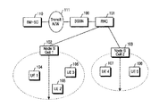
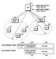
図1は移動通信システムでMBMSサービスを提供するためのネットワーク構造を概略的に示した図である。図1を参照すれば、マルチキャスト/放送サービスセンター(BM−SC:Broadcast/Multicast−Service Center)110はMBMSストリームを提供するソースであり、前記BM−SC110はMBMSサービスに対するストリームをスケジューリングして伝送ネットワーク(N/W)111へ伝送する。前記伝送ネットワーク111は前記BM−SC110とサービスパケット無線サービス支援ノード(SGSN:Serving GPRS Support Node)100との間に存在するネットワークであって、前記BM−SC110からのMBMSストリームを前記SGSN100へ伝送する。ここで、前記SGSN100はゲートウェイパケット無線サービス支援ノード(GGSN:Gateway GPRS Support Node)と外部ネットワークなどで構成することができる。ここでは、任意の時点に前記MBMSサービスを受信しようとする多数のUE、例えば、第1基地局(Node B1)102に属するUE1104、UE2105及びUE3106、第2基地局(Node B2)103に属するUE4107、UE5108が存在すると仮定する。前記SGSN100はUEのMBMS関連サービスを制御する。すなわち、加入者の各々のMBMS課金関連データを管理し、MBMSデータを特定の無線ネットワーク制御器(RNC:Radio Network Controller)101へ選択的に伝送する。さらに、前記SGSN100は前記MBMSサービスXに対するSGSNサービスコンテキスト(SERVICE CONTEXT)を構成して管理し、前記MBMSサービスXに対するストリームを再び前記RNC101へ伝送する。前記RNC101は多数の基地局(Node B)を制御し、自分が管理しているNode Bのうち、MBMSサービスを要求するUEが存在するNode BへMBMSサービスデータを伝送し、前記MBMSサービスを提供するために設定される無線チャンネルを制御し、前記SGSN100からのMBMSサービスストリームを用いて前記MBMSサービスXに対するRNCサービスコンテキスト(SERVICE CONTEXT)を構成して管理する。
【0005】
図1に示したように、一つのNode B1102とそのNode B1102に属するUE1104、UE1105、UE1106との間にはMBMSサービスを提供するために一つの無線チャンネルのみが構成される。さらに、図1に図示していないが、ホーム位置登録器(HLR:Home Location Register)は前記SGSN100と連結されてMBMSサービスのための加入者認証を行う。
【0006】
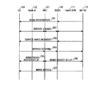
図2は移動通信システムでMBMSサービスを開始するための過程を示した信号流れ図である。図2を参照すれば、BM−SC110は提供可能なMBMSサービスに対するメニュー情報をMBMSサービス加入者であるUEに知らせる(ステップ201)。前記BM−SC110は前記メニュー情報を所定のサービス領域へ放送するか、MBMSサービスを要請するUEのみへ伝送することができる。前記メニュー情報を通じてBM−SC110は各MBMSのサービスを区分するためのMBMSサービス識別子を知らせる。説明の便宜上、前記MBMSサービス加入者をUE104として仮定する。前記メニュー情報を受信したUE104は前記メニュー情報から特定のMBMSサービスを選択し、前記選択したMBMSサービスに対するサービス要請(SERVICE JOINING)メッセージを前記BM−SC110へ送信する。ここで、MBMSサービスの要請においては、前記メニュー情報によるMBMSサービス識別子のうち、そのUEが受けようとするサービス識別子を選択し、前記MBMSサービスを要請するUEの情報をともに送信する。前記サービス要請は図1に示した経路、すなわち、前記UE104からNodeB102、RNC101、SGSN100及び伝送ネットワーク111を通じて前記BM−SC110へ伝送される。前記UE104の特定のMBMSサービスに対するサービス要請を受信したBM−SC110は前記サービス要請に対する応答を前記UE104へ送信する(ステップ202)。この場合も前記サービス要請時と同様に前記サービス要請に対する応答は前記BM−SC110、伝送ネットワーク111、SGSN100及びRNC101を通じて前記UE104へ伝送される。ここで、前記伝送ネットワーク111、SGSN100及びRNC101は前記特定のMBMSサービスを要請したUE104を示すUE識別子を貯蔵し、実際に前記特定のMBMSサービスを開始するとき、前記貯蔵したUE識別子を利用する。このようにネットワーク、すなわち、BM−SC110、伝送ネットワーク111、SGSN100及びRNC101は前記特定のMBMSサービスを受けようとするUEの識別子及びその数を把握する。
【0007】
特定のMBMSサービスに対する要請及び応答が完了された後、前記BM−SC110は特定のMBMSサービスの近い内の開始を示すサービス案内(SERVICEANNOUNCEMENT)メッセージを前記UE104へ送信する(ステップ203)。図2においては、特定のMBMSサービスを受けようとするUEをUE104、すなわち、一つのUEのみが存在すると仮定したが、上述したように、サービス要請及び応答過程でネットワークの構成、すなわち、BM−SC110、伝送ネットワーク111、SGSN100及びRNC101は多数のUEから特定のMBMSサービスに対するサービス要請及び応答がある場合、前記UEの数及び識別子を把握しているため、前記サービス案内メッセージは前記多数のUEの各々へ伝えられる。さらに、前記サービス案内メッセージは前記伝送ネットワーク111、SGSN100及びRNC101を通じてUE104のみへ伝えられる。この際、UMTS(Universal Mobile Telecommunication System)規格に定義されているページング(paging)動作が利用されうる。ここで、前記BM−SC110がサービス案内メッセージを伝送する理由は、ネットワーク上の前記伝送ネットワーク111、SGSN100及びRNC101がMBMSサービスを提供するための伝送路設定による時間的な余裕を許容し、前記MBMSサービスを受けようとするUEを把握するためである。
【0008】
前記サービス案内メッセージを受信したUE104は前記特定のMBMSサービスを受けようとすることを確認するサービス確認(SERVICE CONFIRM)メッセージを前記BM−SC110へ送信する(ステップ204)。前記サービス確認メッセージも前記伝送ネットワーク111、SGSN100及びRNC101を通じてBM−SC110へ伝送されるが、この過程で前記伝送ネットワーク111、SGSN100及びRNC101は前記特定のMBMSサービスが提供されるサービス領域とUEを確認することができ、実際では前記特定のMBMSサービスを提供するための伝送路をセットアップする。このようにネットワーク上に伝送路がセットアップされた状態で前記RNC101はUE104と前記MBMSサービスに対するストリームを伝送するための無線チャンネル、すなわち、MBMS無線ベアラー(Radio Bearer)をセットアップし(ステップ205)、前記SGSN100は前記RNC101と前記MBMSサービスに対するストリームを伝送するための伝送路、すなわち、MBMSベアラーをセットアップする(ステップ206)。ここで、前記RNC101は前記MBMSサービスを要請したUEが存在するNode Bのみに無線ベアラーをセットアップし、同様に前記SGSN101は前記MBMSサービスを要請したUEが存在するRNCのみにMBMSベアラーをセットアップする。このようにネットワーク上に伝送路がセットアップされた状態で前記BM−SC110は該当時点でMBMSサービスに対するストリームを送信し、前記セットアップされた伝送路を通じて前記MBMSサービスに対するストリームが前記UE104へ送信されて実際のMBMSサービスが始まる(ステップ207)。
【0009】
上述したように、MBMSサービスを提供するためには多数の制御情報が必要であり、この制御情報を該当UEの各々へ伝送するためには多数のメッセージ送受信過程が必要である。したがって、MBMSサービスの提供においては、一つの制御メッセージを通じて多数のUEへ制御情報、例えば、無線チャンネル構成情報のような制御情報を伝える方案が必要である。
【0010】
【発明が解決しようとする課題】
従って、本発明の目的は、移動通信システムでMBMSサービスを受けるUEへ前記MBMSサービス別に制御情報を共通で伝送する装置及び方法を提供することにある。
【0011】
本発明の他の目的は、移動通信システムで同じMBMSサービスを受けるUEへ共通チャンネルを通じて無線チャンネル構成情報を伝送する装置及び方法を提供することにある。
【0012】
本発明のまた他の目的は、移動通信システムで同じMBMSサービスを受けるUEへ共通制御チャンネルを通じて無線チャンネル構成情報を伝送する装置及び方法を提供することにある。
【0013】
さらに、本発明の他の目的は、移動通信システムで同じMBMSサービスを受けるUEへ媒体接続制御(MAC:Media Access Control)メッセージを通じて共通制御情報を伝送する装置及び方法を提供することにある。
【0014】
【課題を解決するための手段】
前記目的を達成するための本発明の一側面によれば、多数のサービスを有するマルチメディア放送/マルチキャストサービス(MBMS)を提供する移動通信システムで前記MBMS関連制御情報を伝送する方法は、少なくとも一つの使用者端末機(UE)から前記多数のサービスのうち、特定のMBMSサービスに対するサービス提供要請を受信すると、前記特定のMBMSサービスに対するサービス識別子(ID)を割当てる過程と、前記サービス識別子を割当てた後、前記サービス識別子及び前記特定のMBMSサービス関連制御情報を含む媒体接続制御(MAC)メッセージを前記少なくとも一つの使用者端末機へ伝送する過程とを含むことを特徴とする。
【0015】
前記目的を達成するための本発明の他側面によれば、多数のサービスを有するマルチメディア放送/マルチキャストサービス(MBMS)を提供する移動通信システムで前記MBMS関連制御情報を受信する方法は、前記多数のサービスのうち、特定のMBMSサービスに対するサービス提供を要請した後、前記特定のMBMSサービスに対するサービス識別子(ID)を受信する過程と、前記特定のMBMSサービスに対するサービス識別子を受信した後、共通チャンネルを通じてサービス識別子及びMBMSサービスに対する制御情報を含む媒体接続制御(MAC)メッセージを受信する過程と、前記媒体接続制御メッセージに含まれているサービス識別子が前記特定のMBMSサービスに対するサービス識別子と一致する場合、前記MBMS制御情報に相応する制御動作を行う過程とを含むことを特徴とする。
【0016】
前記目的を達成するための本発明のまた他側面によれば、多数のサービスを有するマルチメディア放送/マルチキャストサービス(MBMS)を提供する移動通信システムで前記MBMS関連制御情報を伝送する装置は、少なくとも一つの使用者端末機(UE)から前記多数のサービスのうち、特定のMBMSサービスに対するサービス提供要請を受信すると、前記特定のMBMSサービスに対するサービス識別子(ID)を割当てる制御器と、前記サービス識別子及び前記特定のMBMSサービス関連制御情報を含む媒体接続制御メッセージを生成する媒体接続制御(MAC)メッセージ生成器とを含むことを特徴とする。
【0017】
前記目的を達成するための本発明のさらにまた他側面によれば、多数のサービスを有するマルチメディア放送/マルチキャストサービス(MBMS)を提供する移動通信システムで前記MBMS関連制御情報を受信する装置は、前記多数のサービスのうち、特定のMBMSサービスに対するサービス提供要請に応じて前記特定のMBMSサービスに対するサービス識別子を受信し、共通チャンネルを通じてサービス識別子及びMBMSサービスに対する制御情報を含む媒体接続制御(MAC)メッセージを受信する受信機と、前記媒体接続制御メッセージに含まれているサービス識別子が前記特定のMBMSサービスに対するサービス識別子と一致する場合、前記MBMS制御情報に相応する制御動作を行うサービス識別子判読器とを含むことを特徴とする。
【0018】
【発明の実施の形態】
以下、本発明による好適な実施形態について添付図面を参照して詳細に説明する。下記説明において、本発明の要旨のみを明瞭にするために公知の機能及び構成に対する詳細な説明は省略する。
【0019】
図3は本発明の一実施形態によるMBMSサービス提供過程を示した信号流れ図である。
【0020】
図3の信号流れを説明する前に、移動通信システム構造は従来技術の図1に示した移動通信システムの構造と同じであると仮定する。さらに、無線ネットワーク制御器(RNC)101が管理するRNC SERVICE CONTEXT)及びサービスパケット無線サービス支援ノード(SGSN)100が管理するSGSN SERVICE CONTEXTについて説明すると、前記RNC101とSGSN100はそれぞれMBMSサービス別にサービス関連情報を管理し、前記MBMSサービス関連情報は“サービスコンテキスト(SERVICE CONTEXT)”として称される。前記MBMSサービス関連情報には、MBMSサービスを受けようとする使用者端末機(UE)のリスト、すなわち、MBMSサービスを受けようとするUEのUE識別子(ID)、前記UEが位置しているサービス領域及びMBMSサービスを提供するために要求されるサービス品質(QoS:Quality of Service)情報などがある。
前記RNC SERVICE CONTEXT、SGSN SERVICE CONTEXTに含まれる情報を具体的に説明する。
第一に、前記RNC SERVICE CONTEXTに含まれる情報は次の通りである。
RNC SERVICE CONTEXT={BM−SCサービス識別子、RNCサービス識別子、MBMSサービスを受信する又は受信しているセルの識別子、該当セルに位置するUEの識別子、MBMSサービスを提供するために必要なQos}
【0021】
上述したように、一つのRNC SERVICE CONTEXTはサービス識別子、多数のセル識別子及び多数のUE識別子情報で構成される。さらに、サービス識別子にはBM−SCサービス識別子とRNCサービス識別子が存在する。前記BM−SCサービス識別子はBM−SC110で提供するMBMSの各々に与えた固有識別子であり、RNCサービス識別子はRNCで提供するMBMSサービスの各々に与えた識別子である。ここで、前記RNCサービス識別子はUE104とRNC101のみが認知し、無線チャンネルを含むRNC101とUE104との伝送路、すなわち、無線ベアラーでサービスを効率的に認知するために与えられる。
第二に、前記SGSN SERVICE CONTEXTに含まれる情報は次の通りである。
SGSN SERVICE CONTEXT={BM−SCサービス識別子、SGSNサービス識別子、MBMSサービスを受信する又は受信しているRNCの識別子、MBMSサービスを提供するために要求されるQoS}
【0022】
前記SGSNサービス識別子はSGSN100で提供するMBMSサービスの各々に与えた識別子であり、UE104とSGSN100との間でMBMSサービスを効率的に認知するために使用される。さらに、前記RNCの識別子の代わりに他の情報が使用されうる。例えば、数個のRNCを一つのサービス領域に予め設定した後、前記サービス領域に対応するサービス領域識別子をRNC識別子の代わりに使用できる。
【0023】
さらに、前記RNC SERVICE CONTEXTとSGSN SERVICE CONTEXTはMBMSサービス提供過程で連続的に更新(アップデート)される。前記RNC101とSGSN100は前記RNC SERVICE CONTEXTとSGSN SERVICE CONTEXTを任意のMBMSサービスに対するストリームを伝送するセル、すなわち、基地局(Node B)とRNCを決定し、サービスを受けているUEの把握に使用する。ここで、図3を参照して実際のMBMSサービスの提供過程を説明する。
【0024】
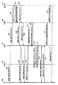
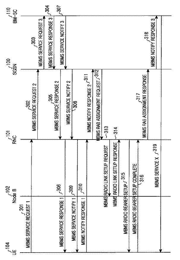
図3を参照すれば、UE104はRNC101に任意のMBMSサービスXに対するサービス提供を要請するために第1MBMSサービス要求(以下、“MBMS SERVICE REQUEST 1”と称する)メッセージを伝送する(ステップ301)。ここで、前記MBMS SERVICE REQUEST 1メッセージには前記UE104がサービスを受けようとするMBMSサービスを示すBM−SCサービス識別子と、前記MBMS SERVICE REQUEST 1メッセージを伝送するUEを示すUE識別子とが含まれる。前記MBMS SERVICE REQUEST 1メッセージを受信したRNC101は構成されているRNCSERVICE CONTEXTを更新し、すなわち、前記RNC SERVICE CONTEXTの受信者関連情報に前記UE104のUE識別子を追加させ、サービス領域関連情報に前記UE104の属するセル、すなわち、Node B(102)のセル識別子を追加させ、前記MBMSサービスXに対するサービス提供を要請する第2MBMSサービス要求(以下、“MBMS SERVICE REQUEST 2”と称する)メッセージをSGSN100へ伝送する(ステップ302)。
【0025】
前記RNC SERVICE CONTEXTの生成及び更新は前記MBMS SERVICE REQUEST 1(ステップ301)メッセージの受信時又は第2MBMSサービス応答(以下、“MBMS SERVICE RESPONSE 2”と称する)メッセージの受信時に行われることができる。今までは前記RNC101が前記RNC SERVICE CONTEXTを更新する場合を説明したが、前記MBMSサービスXが前記RNC101で現在提供しない新たなMBMSサービスである場合、前記RNC101は前記MBMSサービスXに対するRNC SERVICE CONTEXTを新たに構成した後、そのRNC SERVICE CONTEXTに前記情報を管理する。さらに、前記第2MBMSサービス要求メッセージには前記UE104がサービスを受けようとするMBMSサービスを示すBM−SCサービス識別子と、前記第2MBMSサービス要求メッセージを伝送するUE識別子とが含まれる。すなわち、現在MBMSサービスを受けようとする新規UEが存在する場合、既存に前記RNC101に前記MBMSサービスを受けようとするUEが存在したとすれば、MBMSサービスの実行時に無線リンクに対する制御情報をともに伝送するために同じRNCサービス識別子を用いて制御情報を伝送する。前記MBMSサービスを受けようとする新規UEが要請したサービスが新規のものであれば、すなわち、前記RNC101で現在提供しないMBMSサービスの場合、前記新たなMBMSサービスのためのRNCサービス識別子を生成して管理する。ここで、前記RNC101はRNCサービス識別子の割当てをMBMSサービス種類に応じて順次に生成するか、所定の関数を用いて生成することもできる。
これを具体的に説明すると、前記RNC101はUE104からMBMS SERVICEREQUEST 1メッセージを受信するとき、RNC SERVICE CONTEXTを更新又は追加し、新たなRNCサービス識別子が必要であると判断されると、RNCサービス識別子をMBMS SERVICE RESPONSE 2メッセージの受信時又は前記MBMS SERVICE REQUEST 1メッセージの受信時に前記RNCサービス識別子を生成することもできる。ここで、前記RNC101がRNCサービス識別子を生成することは具現上の問題なので、十分に変形が可能である。
【0026】
前記SGSN100は前記RNC101から前記MBMS SERVICE REQUEST 2メッセージの受信により構成されているSGSN SERVICE CONTEXTを更新し、すなわち、前記構成されているSGSN SERVICE CONTEXTの受信者関連情報に前記UE104のUE識別子を追加させ、サービス領域関連情報に前記UE104が属するRNC、すなわち、RNC101の識別子を追加させ、前記MBMSサービスXに対するサービス提供を要請する第3MBMSサービス要求(以下、“MBMS SERVICE REQUEST 3”と称する)メッセージをBM−SC110へ伝送する(ステップ303)。今までは、前記SGSN100が前記SGSN SERVICE CONTEXTを更新する場合を説明したが、前記MBMSサービスXが新たなMBMSサービスである場合、前記SGSN100は前記MBMSサービスXに対するSGSN SERVICE CONTEXTを新たに構成した後、そのSGSN SERVICE CONTEXTに前記情報を管理する。さらに、前記MBMS SERVICE REQUEST 3メッセージにはBM−SCサービス識別子が含まれる。前記MBMS SERVICE REQUEST 3メッセージを受信したBM−SC110は前記MBMS SERVICE REQUEST 3メッセージを送信したSGSN100を前記MBMSサービスXのサービス提供リストに追加させ、前記MBMS SERVICE REQUEST 3メッセージの正常的な受信を示す第3MBMSサービス応答(以下、“MBMS SERVICE RESPONSE 3”と称する)メッセージを前記SGSN100へ送信する(ステップ304)。ここで、前記MBMS SERVICE RESPONSE 3メッセージにはBM−SCサービス識別子が含まれる。
【0027】
前記MBMS SERVICE RESPONSE 3メッセージを受信したSGSN100は前記MBMSサービスXに対するサービス識別子、すなわち、SGSNサービス識別子を前記SGSN SERVICE CONTEXTのサービス識別子関連情報に追加する形態で更新した後、前記MBMS SERVICE REQUEST 3メッセージの正常的な受信を示す第2MBMSサービス応答(以下、“MBMS SERVICE RESPONSE 2”と称する)メッセージを前記RNC101へ送信する(ステップ305)。ここで、前記SGSN100は前記MBMS SERVICE REQUEST 3メッセージを受信するにつれて前記SGSNサービス識別子を割当てるが、これは前記MBMSサービスXに対応して前記SGSN100で管理するサービス識別子である。前記第2MBMSサービス応答メッセージを受信したRNC101はRNCサービス識別子を割当て、前記割当てたRNCサービス識別子を前記RNC SERVICE CONTEXTのサービス識別子関連情報に追加する形態で更新した後、前記MBMS SERVICE REQUEST 2メッセージの正常的な受信を示す第1MBMSサービス応答(以下、“MBMS SERVICE RESPONSE 1”と称する)メッセージを前記UE104へ送信する(ステップ306)。ここで、前記RNCサービス識別子関連情報をMBMS SERVICE RESPONSE 1メッセージに載せてUEへ送信することもできる。前記RNC101は前記MBMS SERVICE RESPONSE 2メッセージを受信するにつれてRNCサービス識別子を割当てるが、これは前記MBMSサービスXに対応して前記RNC101で管理するサービス識別子である。ここで、前記MBMS SERVICE RESPONSE 1メッセージにはBM−SCサービス識別子、SGSNサービス識別子及びRNCサービス識別子が含まれている。前記 MBMS SERVICE RESPONSE 1メッセージを受信したUE104は前記SGSNサービス識別子とRNCサービス識別子を貯蔵した後、待機する。
【0028】
一方、前記BM−SC110は前記MBMSサービスXの近い内の開始を通知し、前記MBMSサービスXの提供を望むUEのリスト、すなわち、UEの識別子を把握するための第3MBMSサービス通知(以下、“MBMS SERVICE NOTIFY 3”と称する)メッセージを前記SGSN110へ送信する(ステップ307)。ここで、前記MBMS SERVICE NOTIFY 3メッセージにはBM−SCサービス識別子、前記MBMSサービスXの実際サービス開始時間及びQoS関連情報が含まれている。前記MBMS SERVICE NOTIFY 3メッセージを受信したSGSN100は伝送ネットワーク111上に前記MBMSサービスXを提供するための無線ベアラーを設定する。さらに、前記SGSN100は前記MBMSサービスXのためのIu連結をセットアップし、QoS関連情報及びサービス領域関連情報中のIu連結関連情報を前記SGSN SERVICE CONTEXTに更新した後、MBMSサービスXの近い内の開始を通知し、前記MBMSサービスXの提供を望むUEのリストを把握するための第2MBMSサービス通知(以下、“MBMS SERVICE NOTIFY 2”と称する)メッセージを前記RNC101へ送信する(ステップ308)。ここで、前記MBMS SERVICE NOTIFY 2メッセージにはBM−SCサービス識別子、SGSNサービス識別子、サービス開始時間及びQoS関連情報が含まれている。前記MBMS SERVICENOTIFY 2メッセージを受信したRNC101は管理しているRNC SERVICE CONTEXTに存在するUE識別子及び前記UEの属するセルを確認し、前記UEへ前記MBMSサービスXの近い内の開始を通知する第1MBMSサービス通知(以下、“MBMS SERVICE NOTIFY 1”と称する)メッセージを前記UE104へ送信する(ステップ309)。ここで、前記MBMS SERVICE NOTIFY 1メッセージにはBM−SCサービス識別子、RNCサービス識別子、サービス開始時間及びQoS関連情報が含まれている。
【0029】
前記MBMS SERVICE NOTIFY 1メッセージを受信したUE104は前記MBMSサービスXを受けるか否かを決定し、前記受信したQoS関連情報を貯蔵した後、前記MBMS SERVICE NOTIFY 1メッセージの正常的な受信を示す第1MBMS通知応答(以下、“MBMS NOTIFY RESPONSE 1”と称する)メッセージを前記RNC101へ送信する(ステップ310)。ここで、前記MBMS NOTIFY RESPONSE 1メッセージにはRNCサービス識別子及びUE識別子が含まれている。前記MBMS NOTIFY RESPONSE 1メッセージを受信したRNC101は前記MBMS NOTIFY RESPONSE 1メッセージを伝送したUEのUE識別子及び前記UEの属するセルのセル識別子を前記RNC101が管理しているRNC SERVICE CONTEXTに追加する形態で更新し、前記MBMS SERVICE NOTIFY 2メッセージの正常的な受信を示す第2MBMS通知応答(以下、“MBMS NOTIFY RESPONSE 2”と称する)メッセージを前記SGSN100へ送信する(ステップ311)。前記ステップ310では前記RNC101が前記UE104のみからMBMS NOTIFY RESPONSE 1メッセージを受信する場合を仮定したが、多数のUEから前記MBMS NOTIFY RESPONSE 1メッセージを受信することもできる。この場合、前記多数のUEの各々に対するUE識別子及び前記UEの属するセルのセル識別子を前記RNC SERVICE CONTEXTに追加する形態で更新する。
【0030】
一方、前記MBMS NOTIFY RESPONSE 2メッセージにはBM−SCサービス識別子及びUE識別子が含まれている。前記MBMS NOTIFY RESPONSE 2メッセージを受信したSGSN100は管理しているSGSN SERVICE CONTEXTを前記MBMS NOTIFY RESPONSE 2メッセージに含まれているUE識別子とRNC識別子を追加する形態で更新する。さらに、前記SGSN100は前記MBMS NOTIFY RESPONSE 2メッセージを送信した前記RNC101に前記MBMSサービスXに対するストリームを伝送するための伝送路、すなわち、無線接続ベアラー(RAB:Radio Access Bearer)を設定するためのRAB割当て要求(以下、“RAB ASSIGNMENT REQUEST”と称する)メッセージを送信する(ステップ312)。ここで、前記RAB ASSIGNMENT REQUESTメッセージにはBM−SCサービス識別子及びQoS情報が含まれている。前記RAB ASSIGNMENT REQUESTメッセージを受信したRNC101は管理しているRNC SERVICE CONTEXTに識別子が存在するセルとUEを確認し、前記受信したQoS情報に応じて前記セル、すなわち、Node B(102)へ無線リンク設定のための準備動作を行う。この際、前記RNCサービス識別子に対する情報を伝送することにより、従来ではサービスのために各々のUEへ個別的に伝送した無線リンクに対する情報を一括的にRNCサービス識別子を通じて伝送する。前記RNC101は前記UE104が順方向アクセスチャンネルCell_FACH(Forward Access Channel)状態にある場合、FACHを通じて前記制御情報を一括的に伝送する。さらに、前記RNC101は前記UE104が専用チャンネルCell_DCH(Dedicated Channel)状態にある場合は従来と同じ方法で前記制御情報を伝送するか、前記UE104にCell_FACH状態への状態遷移を要請してFACHを通じてMBMSサービスを伝送するチャンネルに対する制御情報を伝送し、その情報を受信して実際のMBMSサービスデータを受けるチャンネルに関する無線リンクを構成する。前記UE104は前記RNC101と無線ベアラーをセットアップする準備を行う。その後、前記RNC101は前記MBMSサービスXに対するストリームを伝送するための前記無線リンクの設定を要求するMBMS無線リンクセットアップ要求(以下、“MBMS RADIO LINK SETUP REQUEST”と称する)メッセージを前記Node B(102)へ送信する(ステップ313)。ここで、前記MBMS RADIO LINK SETUP REQUESTメッセージには前記MBMSサービスXに対するストリームを伝送する無線リンクに適用されるチャンネル化コード情報及びスクランブリングコード(scrambling code)情報が含まれている。前記MBMS RADIO LINK SETUP REQUESTメッセージを受信したNode B(102)は前記MBMS RADIO LINK SETUP REQUESTメッセージに含まれている前記チャンネル化コード情報及びスクランブリングコード情報を用いて無線リンクをセットアップした後、前記RNC101へ無線リンクセットアップの実行を示すMBMS無線リンクセットアップ応答(以下、“MBMS RADIO LINK SETUP RESPONSE”と称する)メッセージを送信する(ステップ314)。
【0031】
前記RNC101は前記MBMS RADIO LINK SETUP RESPONSEメッセージを受信し、前記MBMS RADIO LINK SETUP RESPONSEメッセージを送信した前記Node B(102)内のセルに位置するUE104に無線ベアラーの設定を要求するMBMS無線ベアラーセットアップ(以下、“MBMS RADIO BEARER SETUP”と称する)メッセージを送信する(ステップ315)。ここで、前記MBMS RADIO BEARER SETUPメッセージにはRNCサービス識別子、サービス開始時間、チャンネル化コード情報及びスクランブリングコード情報が含まれている。前記MBMS RADIO BEARER SETUPメッセージを受信したUE104は前記受信したMBMS RADIO BEARER SETUPメッセージに含まれている情報を用いてMBMS無線ベアラーを設定した後、前記RNC101にMBMS無線ベアラーセットアップの完了を示すMBMS無線ベアラーセットアップ完了(以下、“MBMS RADIO BEARER SETUP COMPLETE”と称する)メッセージを送信する(ステップ316)。ここで、前記MBMS RADIO BEARER SETUP COMPLETEメッセージにはRNCサービス識別子及びUE識別子が含まれている。前記MBMS RADIO BEARER SETUP COMPLETEメッセージを受信したRNC101は管理しているRNC SERVICE CONTEXTに前記無線ベアラーセットアップ完了メッセージを送信したUE104の識別子を追加する形態で更新した後、MBMSサービスXに対する伝送路構成の完了を示すMBMSRAB割当て応答(以下、“MBMS RAB ASSIGNMENT RESPONSE”と称する)メッセージを前記SGSN100へ送信する(ステップ317)。ここで、前記MBMS RAB ASSIGNMENT RESPONSEメッセージにはBM−SCサービス識別子及び多数のUE識別子が含まれている。前記MBMS RAB ASSIGNMENT RESPONSEメッセージを受信したSGSN100は管理しているSGSN SERVICE CONTEXTに前記MBMS RAB ASSIGNMENT RESPONSEメッセージに含まれているUEの識別子を追加する形態で更新した後、前記MBMSサービスXに対する受信準備動作の完了を示す第3MBMS通知応答(以下、“MBMS NOTIFY RESPONSE 3”と称する)メッセージをBM−SC110へ送信する(ステップ318)。前記MBMS NOTIFY RESPONSE 3メッセージにはサービス識別子が含まれている。ここで、前記MBMS NOTIFY RESPONSE 3メッセージに含まれているサービス識別子はインターネットプロトコル(IP:Internet Protocol)マルチキャストアドレス(multicast address)である。前記BM−SC110が前記MBMS NOTIFY RESPONSE3メッセージを受信するにつれて前記BM−SC110とUE104との間にはMBMSサービスXに対するストリームが提供される(ステップ319)。
【0032】
前記任意のMBMSサービスXを開始するためのメッセージ種類及び各構成部の動作を表1A,1B及び表2A,2Bに示す。説明の便宜上、前記メッセージの名称を下記の表に示したように表記したが、そのメッセージ名称は変更が可能である。
【表1A】
上述したメッセージのうち、MBMS RAB ASSIGNMENT REQUESTメッセージ、MBMS RAB ASSIGNMENT RESPONSEメッセージ、MBMS RADIO LINK SETUP REQUESTメッセージ、MBMS RADIO LINK SETUP RESPONSEメッセージ、MBMS RADIO BEARER SETUPメッセージ及びMBMS RADIO BEARER SETUP COMPLETEメッセージは新たに定義されるか、現在のUMTS(Universal Mobile Telecommunication System)標準規格で使用されるRAB ASSIGNMENT REQUESTメッセージ、RAB ASSIGNMENT RESPONSEメッセージ、RADIO LINK SETUP REQUESTメッセージ、RADIO LINK SETUP RESPONSEメッセージ、RADIO BEARER SETUPメッセージ及びRADIO BEARER SETUP COMPLETEメッセージを変形した形態として定義される。但し、前記メッセージには前記MBMSサービスのための各種情報が含まれる。
【0034】
一方、図3に示したMBMSサービス提供過程で前記MBMSサービスを受けるUEが多数である場合、前記多数のUEの各々にMBMS RADIO BEARER SETUPメッセージを通じてチャンネル化コード情報及びスクランブリングコード情報などの前記MBMSサービスストリームを受信するための無線チャンネルの構成情報が伝えられる。ここで、前記無線チャンネルの構成情報を前記多数のUEの各々に伝える方法には二種がある。その第一はUEの各々にMBMS RADIO BEARER SETUPメッセージを伝送する方法であり、第二は一つのセルに属するUEに同じ一つのMBMS RADIO BEARER SETUPメッセージを伝送する方法である。前記第一の方法は一般的なUMTSで適用する方法をそのまま適用する、すなわち、UEの各々に一対一に無線チャンネルの構成情報を伝送することであり、前記第二の方法は本発明で提案する無線チャンネルの構成情報を伝送する方法である。
【0035】
図4及び図5を参照して一つの制御メッセージを通じて多数のUEに無線チャンネル構成情報を伝送する方法を説明する。
【0036】
図4は本発明の第1実施形態によるMBMSサービスのための無線チャンネル構成情報伝送を概略的に示した図である。
【0037】
UE1421、UE2422、UE3423、UE4431及びUE5432が任意のMBMSサービスである第1MBMSサービスを要請し、その第1MBMSサービスの要請に応じて図3に示したステップ301からステップ314まで、すなわち、MBMS無線リンクセットアップまで完了された状態にあると仮定する。さらに、前記UE1421、UE2422、UE3423及びUE4431はFACH受信情報及びランダムアクセスチャンネル(RACH:Random Access Channel)情報を認知しており、前記UE1421、UE2422、UE3423及びUE4431はFACHを通じて伝送されるメッセージを受信する状態(以下、“Cell_FACH状態”と称する)に、UE5431はDCHを設定している状態(以下、“Cell_DCH状態”と称する)にあると仮定する。
【0038】
図4を参照すれば、RNC410は前記UEの各々に対して一つのMBMS RADIOBEARER SETUPメッセージを伝送し、前記UEはMBMS RADIO BEARER SETUPメッセージに対する応答として前記RNC410へMBMSRADIO BEARER SETUP COMPLETEメッセージを伝送する。前記RNC410はCell_FACH状態にあるUE、すなわち、UE1421乃至UE4431には各セルにセットアップされているFACHを通じてMBMS RADIO BEARER SETUPメッセージを伝送するが、このときにFACHを通じて伝送されるメッセージの構成は図4に示した通りである。すなわち、前記FACHは多数のUEが共有するチャンネルなので、FACHを通じて伝送されるメッセージには前記FACHを受信する受信UEを指定すべきであるが、UE識別子情報440に前記FACHを受信するUEを示すUE識別子が含まれる。ここで、前記UE識別子情報はUEが最初にシステムに接続するときにUE別に割当てられるが、16ビット又は32ビットで構成される。その他の制御情報450は前記UE識別子情報440を除いた残り制御情報、例えば、多重化情報を示し、ペイロード(PAYLOAD)460には前記MBMS RADIO BEARER SETUPメッセージに含まれる情報が存在する。
【0039】
一方、前記RNC410はCell_DCH状態にあるUE、すなわち、UE5431にはDCHを通じてMBMS RADIO BEARER SETUPメッセージを伝送する。前記DCHは特定のUEに専用で割当てられるチャンネルなので、前記DCHを通じて伝送されるMBMS RADIO BEARER SETUPメッセージのメッセージフォーマットはUE識別子情報を別途に必要とせず、その他の制御情報470と前記ペイロード480のみを有する。図4において、前記FACHは共通チャンネルとしてセル境界地域まで伝送されるため、FACHによるMBMS RADIO BEARER SETUPメッセージはセル境界地域まで点線で表示し、前記DCHは専用チャンネルとして該当UE、すなわち、UE5432まで伝送電力制御を通じて伝送されるので、前記DCHによるMBMS RADIO BEARER SETUPメッセージは前記UE5432まで実線で表示した。
【0040】
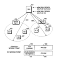
図5は本発明の第2実施形態によるMBMSサービスのための無線チャンネル構成情報伝送を概略的に示した図である。
【0041】
UE1521、UE2522、UE3523、UE4531及びUE5532が任意のMBMSサービスである第1MBMSサービスを要請し、その第1MBMSサービスの要請に応じて図3に示したステップ301からステップ314まで、すなわち、MBMS無線リンクセットアップまで完了された状態にあると仮定する。さらに、前記UE1521、UE2522、UE3523及びUE4531はFACH受信情報及びRACH情報を認知しており、前記UE1521、UE2522、UE3523及びUE4531はFACHを通じて伝送されるメッセージを受信するCell_FACH状態に、UE5531はDCHを設定しているCell_DCH状態にあると仮定する。
【0042】
図5を参照すれば、RNC510は同じセルに位置しており、Cell_FACH状態にあるUE1521、UE2522及びUE3523にFACHを用いてMBMS RADIO BEARER SETUPメッセージを伝送する。この際、FACHを通じて伝送されるMBMS RADIO BEARER SETUPメッセージの構成は図5に示した通りである。すなわち、前記FACHは多数のUEが共有するチャンネルなので、FACHを通じて伝送されるメッセージには前記MBMS RADIO BEARER SETUPメッセージがどのMBMSサービスに対するMBMS RADIO BEARER SETUPメッセージであるかを示すRNCサービス識別子情報540が含まれる。すなわち、FACHを通じて伝送される各UEの識別子の代わりに同じMBMSサービスを受けようとするUEにRNCサービス識別子情報を伝送することにより、既存に各々のUEへ送信した制御情報を一括的に送信して不必要な無線資源の浪費を防止する。上述したように、サービスを受けようとするUEがCell_DCH状態にあれば、前記Cell_DCH状態のUEをCell_FACH状態へ遷移させて前記MBMSサービスを提供する無線チャンネルに対する制御情報を受信するようにする。ここで、前記RNCサービス識別子情報はMBMSサービス種類に応じて順次に割当てられるか、所定の関数に応じて生成されることもできる。前記RNC510は前記MBMS SERVICE REQUEST1に応じて前記RNCサービス識別子情報540を設定して前記MBMS SERVICE RESPONSE 1メッセージを通じて該当UEに知らせる。その他の制御情報550は前記RNCサービス識別子情報540を除いた残り制御情報を示し、ペイロード(PAYLOAD)560には前記MBMS RADIO BEARER SETUPメッセージを含む情報が存在する。さらに、前記RNC510はUE4531もCell_FACH状態にあるため、該当FACHを用いてMBMS RADIO BEARER SETUPメッセージを伝送し、UE5532はCell_DCH状態にあるため、DCHを用いて前記MBMS RADIO BEARER SETUPメッセージを伝送する。
【0043】
一方、前記DCHは特定のUEに専用で割当てられるチャンネルなので、前記DCHを通じて伝送されるMBMS RADIO BEARER SETUPメッセージのメッセージフォーマットはRNC識別子情報を別途に必要とせず、その他の制御情報570とペイロード580のみを有する。図5において、前記FACHは共通チャンネルとしてセル境域地域まで伝送されるので、FACHによるMBMS RADIO BEARER SETUPメッセージはセル境域地域まで点線で表示し、前記DCHは専用チャンネルとしてUE5532まで伝送電力制御を通じて伝送されるので、前記DCHによるMBMS RADIO BEARER SETUPメッセージは前記UE5532まで実線で表示した。
【0044】
図6は本発明の実施形態における機能を行うためのUE構造を示した図である。
【0045】
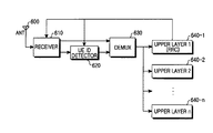
図6を参照すれば、アンテナ600を通じて受信された無線周波数(RF:Radio Frequency)信号は受信部610へ伝えられる。前記受信部610は上位階層、例えば、無線資源制御(RRC:Radio Resource Control)階層(640−1〜640−n)の制御に応じて前記アンテナ600を通じて受信される信号に適用するチャンネル化コードを認知する。さらに、前記受信部610は前記認知したチャンネル化コードを用いて前記アンテナ600からの受信信号を逆拡散した後、所定のサイズにセグメント及びCRC(Cyclic Redundancy Check)演算などの過程を通じて図4及び図5に示したMBMS RADIO BEARER SETUPメッセージとして処理してUE識別子判読部620及び逆多重化器(DEMUX)630に出力する。前記RRC階層640−1はUEがCell_FACH状態にある場合、前記受信部610がFACH信号を受信するように制御し、UEがCell_DCH状態にある場合は前記受信部610がDCH信号を受信するように制御する。すなわち、前記UEがCell_FACH状態にある場合、前記受信部610は受信処理したMBMS RADIO BEARER SETUPメッセージをUE識別子判読部620へ伝え、前記UEがCell_DCH状態にある場合は前記受信部610は受信処理したMBMS RADIO BEARER SETUPメッセージを逆多重化器630へ伝える。ここで、前記UEがCell_FACH状態にある場合、前記UEはFACHを通じてMBMS RADIO BEARER SETUPメッセージを受信するが、前記FACHは多数のUEが共有するチャンネルなので、前記FACHを通じて受信したMBMS RADIO BEARER SETUPメッセージが前記UEの自分に該当するメッセージであるかを判断するために前記受信したMBMS RADIO BEARER SETUPメッセージを前記UE識別子判読部620に出力する。これとは反対に前記UEがCell_DCH状態にある場合、前記UEはDCHを通じてMBMS RADIO BEARER SETUPメッセージを受信するが、前記DCHは前記UEの専用チャンネルなので、前記DCHを通じて受信したMBMS RADIO BEARER SETUPメッセージは前記UEに該当するメッセージである。したがって、前記UEは前記受信したMBMS RADIO BEARER SETUPメッセージを前記逆多重化器630に出力する。
【0046】
前記UE識別子判読部620は前記UEを示すUE識別子を予め認知しており、前記受信部610によるMBMS RADIO BEARER SETUPメッセージのUE識別子情報440に含まれているUE識別子と前記予め認知したUE識別子とを比較する。その結果、前記MBMS RADIO BEARER SETUPメッセージのUE識別子情報440に含まれているUE識別子と前記UEの自分のUE識別子が一致する場合のみ、前記UE識別子判読部620は前記受信したMBMS RADIO BEARER SETUPメッセージを前記逆多重化器630に出力する。
【0047】
以上の説明では、前記UE識別子判読部620がUE識別子情報440を用いて受信したMBMS RADIO BEARER SETUPメッセージが前記UEの自分に該当するメッセージであるかを判断したが、これは図4で説明した本発明の第1実施形態によることである。これとは異なり、図5で説明したように本発明の第2実施形態による動作を行うこともできる。すなわち、前記UE識別子判読部620は前記UE識別子の代わりに前記UEがサービス要求したMBMSサービスを示すRNCサービス識別子を予め認知し、前記UE識別子判読部620は前記受信部610から出力されるMBMS RADIO BEARER SETUPメッセージに含まれているRNC識別子情報540が前記UEによりサービス要求されたRNCサービス識別子と一致する場合のみ、前記MBMS RADIO BEARER SETUPメッセージを逆多重化器630へ伝える。すなわち、前記UE識別子判読部620はUE識別子又はUEによりサービス要求されたMBMSサービスを示すRNCサービス識別子を用いて受信したMBMS RADIO BEARER SETUPメッセージがUEの自分に該当するメッセージであるかを判断する。
【0048】
前記逆多重化器630は本発明の第1実施形態では前記受信部610又は前記UE識別子判読部620からMBMS RADIO BEARER SETUPメッセージの他の制御情報、例えば、前記UEがFACHを通じて前記MBMS RADIO BEARER SETUPメッセージを受信した場合は図4の他の制御情報450を、これとは異なり、前記UEがDCHを通じて前記MBMS RADIO BEARER SETUPメッセージを受信した場合は図4の他の制御情報470を用いて前記MBMS RADIO BEARER SETUPメッセージのペイロード460又はペイロード480を該当の上位階層へ伝えて前記MBMS RADIOBEARER SETUPメッセージを処理する。一方、前記逆多重化器630は本発明の第2実施形態では前記受信部610又は前記UE識別子判読部620からMBMS RADIO BEARER SETUPメッセージの他の制御情報、例えば、前記UEがFACHを通じて前記MBMS RADIO BEARER SETUPメッセージを受信した場合は図5の他の制御情報550を、これとは異なり、前記UEがDCHを通じて前記MBMS RADIO BEARER SETUPメッセージを受信した場合は図5の他の制御情報570を用いて前記MBMS RADIO BEARER SETUPメッセージのペイロード560又はペイロード580を該当上位階層へ伝えて前記MBMS RADIO BEARER SETUPメッセージを処理する。
【0049】
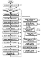
図7は図6のUE動作過程を示したフローチャートである。
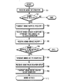
図7を参照すれば、ステップ701でメニュー情報を受信したUEはステップ702へ進行する。ステップ702で前記UEは特定のMBMSサービス受信を望む場合、ステップ703へ進行する。ステップ703で前記UEはRNCへMBMS SERVICE REQUEST 1メッセージを送信する。ここで、前記MBMS SERVICE REQUEST 1メッセージには受信を望むMBMSサービスを示すBM−SCサービス識別子が含まれる。前記BM−SCサービス識別子は、上述したように、BM−SCから各MBMSサービスを区分するために割当てられた識別子である。ステップ704で前記UEはその状態に応じて適宜なチャンネルを監視する。すなわち、前記UEがCell_FACH状態にある場合はFACHを、Cell_DCH状態にある場合はDCHを監視して前記監視チャンネルを通じて前記RNCからMBMS SERVICE RESPONSE 1メッセージが受信されると、前記MBMS SERVICE RESPONSE 1メッセージに含まれているRNCサービス識別子をUE識別子判読部620へ伝送し、ステップ705へ進行する。すなわち、前記UEはRNCサービス識別子に応じてMBMSサービスを受けるチャンネルを構成する。その後、前記UEはその状態に応じて適宜なチャンネルを監視し、ステップ705で前記RNCからMBMS SERVICE NOTIFY 1メッセージを受信すると、ステップ706へ進行する。ステップ706で前記UEは前記受信したMBMS SERVICE NOTIFY 1メッセージに含まれているサービス識別子を検出して前記サービス識別子に該当するMBMSサービスを受けるかを決定した後、ステップ707へ進行する。ここで、前記MBMS SERVICE NOTIFY 1メッセージにはBM−SCサービス識別子及びRNCサービス識別子が含まれる。ステップ707で前記UEは前記サービス識別子に該当する特定のMBMSサービスの提供を決定すると、MBMS SERVICE NOTIFY RESPONSEメッセージを前記RNCへ送信した後、ステップ708へ進行する。ステップ708で前記UEはその状態に応じて適宜なチャンネルを監視して前記RNCからMBMS RADIO BEARER SETUPメッセージを受信すると、前記受信したMBMS RADIO BEARER SETUPメッセージに含まれている無線チャンネル構成情報に応じて前記特定のMBMSサービスに対するデータを受信するための無線ベアラーをセットアップし、前記UEは前記受信したMBMS RADIO BEARER SETUPメッセージに含まれているサービス開始時間を貯蔵して前記サービス開始時間に合わせて前記MBMSデータを受信するように前記受信部610を制御する。ここで、前記UEがCell_FACH状態にある場合は前記MBMS RADIO BEARER SETUPメッセージに識別子としてRNCサービス識別子が挿入され、UE識別子判読部620はステップ704からのRNCサービス識別子を用いて前記受信したMBMS RADIO BEARER SETUPメッセージがUEの自分に該当するメッセージであるかを判断する。その結果、前記受信したMBMSRADIO BEARER SETUPメッセージが前記UEの自分に該当するメッセージである場合、前記UEは上述したように無線ベアラーをセットアップし、前記無線ベアラーセットアップが完了されると、前記UEはステップ709へ進行する。ステップ709で前記UEは前記無線ベアラーセットアップの完了によりMBMS RADIOBEARER SETUP COMPLETEメッセージを前記RNCへ送信する。その後、ステップ710で前記UEは前記貯蔵したサービス開始時間に前記MBMSデータの受信を前記無線ベアラーを通じて開始する。
【0050】
図7では、前記UEが本発明の第2実施形態に相応するようにRNC識別子情報を用いてMBMSサービスのための無線ベアラーセットアップを行う場合を説明したが、本発明の第1実施形態のようにUE識別子情報を用いてMBMSサービスのための無線ベアラーセットアップを行うこともできる。
【0051】
図8は本発明の実施形態における機能を行うためのUTRAN(Universal Terrestrial Radio Access Network)構造を示した図である。ここで、前記UTRANはNode BとRNCを総称する用語である。
【0052】
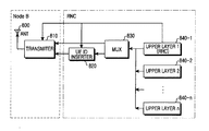
図8を参照すれば、MBMS SERVICE RESPONSE 2メッセージを受信したRNCは該当MBMSサービスに対するRNCサービス識別子を割当てた後、前記割当てRNCサービス識別子をUE識別子挿入部820に伝える。上位階層(RRC)840−1,…,840−nは伝送するデータが存在する場合、前記伝送データを多重化器(MUX)830へ伝える。ここで、図示していないが、前記上位階層840−1,…,840−nと前記多重化器830との間には前記上位階層840−1,…,840−nからの出力データを所定のサイズにセグメントし、そのセグメントデータに一連番号を与えるなど、データ処理のための別途の要素を構成することもできる。前記多重化器830は前記上位階層840−1,…,840−nからの出力データを多重化情報と多重化して前記多重化信号がDCHを通じて伝送される場合は送信部810へ、前記多重化信号がFACHを通じて伝送される場合はUE識別子挿入部820へ伝える。前記UE識別子挿入部820は前記多重化器830からの信号に該当識別子を挿入した後、前記Node Bの送信部810に出力する。ここで、前記UE識別子挿入部820は前記多重化器830からの出力信号にRNCサービス識別子とUE識別子のうち、どの識別子を挿入するかを前記多重化情報又は前記上位階層840−1,…,840−nの制御に応じて決定する。例えば、前記多重化情報が0又は1である場合はRNCサービス識別子を挿入し、その他の場合はUE識別子を挿入するように予め設定することができる。さらに、前記RNCサービス識別子の挿入を要するデータがUE識別子挿入部820へ伝えられると、前記上位階層840−1,…,840−nの制御に応じて前記RNCサービス識別子を挿入する。前記UE識別子挿入部820又は前記多重化器830からの出力データは前記送信部810で無線周波数(RF)信号に変換されてアンテナ800を通じて送信される。
【0053】
図9は図8のUTRAN動作過程を示したフローチャートである。
【0054】
図9を参照すれば、ステップ901でRNCはMBMS SERVICE REQUEST 1メッセージを受信すると、ステップ902へ進行する。ステップ902で前記RNCは前記MBMS SERVICE REQUEST 1メッセージに含まれているBM−SCサービス識別子に該当するRNC SERVICE CONTEXTが存在するかを検査する。その検査結果、前記BM−SCサービス識別子に該当するRNC SERVICE CONTEXTが存在しない場合、前記RNCはステップ903へ進行する。ステップ903で前記RNCは前記BM−SCサービス識別子に該当する新たなRNC SERVICE CONTEXTを生成し、ステップ904へ進行する。ステップ902で前記BM−SCサービス識別子に該当するRNC SERVICE CONTEXTが既に存在する場合、前記RNCはステップ904へ進行する。ステップ904で前記RNCは前記生成されているRNC SERVICE CONTEXTに前記MBMS SERVICE REQUEST 1メッセージを伝送したUEを示すUE識別子と、前記UEが位置しているセルを示すセル識別子とを追加して更新した後、ステップ905へ進行する。
【0055】
ステップ905で前記RNCは前記SGSNへ前記UE識別子を含むMBMS SERVICE REQUEST 2メッセージを送信した後、ステップ906へ進行する。前記SGSNは前記MBMS SERVICE REQUEST 2メッセージを用いてMBMSサービスを受けようとするUEと前記UEを管理するRNCとを把握することができる。ステップ906で前記RNCは前記SGSNから前記MBMS SERVICE REQUEST 2メッセージに相応するMBMS SERVICE RESPONSE 2メッセージを受信し、ステップ907へ進行する。ステップ907で前記RNCは前記MBMS SERVICE RESPONSE 2メッセージを受信すると、RNCサービス識別子を決定し、その決定RNCサービス識別子をUE識別子挿入部820へ伝送し、ステップ908へ進行する。ここで、前記RNCサービス識別子は他のMBMSサービスに割当てられない識別子中の一つとして決定される。ステップ902で説明したように、前記RNC SERVICE CONTEXTが既に存在する場合はRNCサービス識別子も既に割当てられたので、この場合はRNCサービス識別子を再び割当てる必要がない。
【0056】
ステップ908で前記RNCはRNCサービス識別子が含まれているMBMS SERVICE RESPONSE 1メッセージを前記UEへ伝送し、ステップ909へ進行する。ステップ909で前記RNCは前記SGSNからMBMS SERVICE NOTIFY 2メッセージを受信し、ステップ910へ進行する。ステップ910で前記UEは前記受信したMBMS SERVICE NOTIFY 2メッセージの受信により該当RNC SERVICE CONTEXTに登録されているUE識別子に該当するUEへMBMS SERVICE NOTIFY 1メッセージを送信し、ステップ911へ進行する。ステップ911で前記RNCは前記該当UEからMBMS SERVICE NOTIFY RESPONSE 1メッセージを受信し、ステップ912へ進行する。ステップ912で前記RNCは前記MBMS SERVICE NOTIFY RESPONSE 1メッセージを送信したUEに対するUE識別子と、前記UEの属するセルの識別子とを前記RNC SERVICE CONTEXTに追加して更新した後、ステップ913へ進行する。ステップ913で前記RNCは前記SGSNへMBMS SERVICE NOTIFY RESPONSE 2メッセージを送信し、ステップ914へ進行する。ステップ914で前記RNCは前記SGSNからMBMS RAB ASSIGNMENT REQUESTメッセージを受信した後、ステップ915へ進行する。
【0057】
ステップ915で前記RNCは前記MBMS RAB ASSIGNMENT REQUESTメッセージに含まれているQoS情報に基づいて無線チャンネルセットアップを準備した後、ステップ916へ進行する。すなわち、前記RNCは前記RNC SERVICE CONTEXTに登録されているセルを管理するNode BへMBMS RADIO LINK SETUP REQUESTメッセージを送信し、ステップ916へ進行する。ここで、前記MBMS RADIO LINK SETUP REQUESTメッセージにはMBMSデータが伝送される無線チャンネルに関する無線チャンネル構成情報が含まれ、前記Node Bは前記無線チャンネル構成情報に基づいて前記送信部810を制御する。前記送信部810の制御が完了されると、前記Node BはMBMS RADIO LINK SETUP RESPONSEメッセージを前記RNCへ伝送する。ステップ916で前記Node Bから前記MBMS RADIO LINK SETUP RESPONSEメッセージを受信した前記RNCはステップ917へ進行して該当UEにMBMS RADIO BEARER SETUPメッセージを送信し、ステップ919へ進行する。ここで、前記該当UEのうち、Cell_DCH状態にあるUEに対して前記RNCはステップ918へ進行してMBMS RADIO BEARER SETUPメッセージをDCHを通じて伝送した後、ステップ919へ進行し、前記該当UEのうち、Cell_FACH状態にあるUEに対して前記RNCはステップ917で前記FACHを通じてMBMS RADIO BEARER SETUPメッセージを伝送した後、ステップ919へ進行する。ステップ919で前記RNCは該当UEからMBMS RADIO BEARER SETUP COMPLETEメッセージを受信し、ステップ920へ進行する。ステップ920で前記RNCは前記MBMSデータ伝送のための無線チャンネルセットアップの完了をMBMS RAB ASSIGNMENT RESPONSEメッセージを用いてSGSNに通告し、ステップ921へ進行する。ステップ921で前記RNCは前記セットアップされている無線チャンネルを通じてMBMSデータ、すなわち、MBMSストリームを伝送する。
【0058】
次に、前記MBMS RADIO BEARER SETUPメッセージを共通制御チャンネル(CCCH)を通じて伝送する本発明の第3実施形態を説明する。
【0059】
図10は本発明の第3実施形態によるCCCHを通じたMBMSサービスのための無線チャンネル構成情報伝送を概略的に示した図である。
【0060】
図10を説明する前に図5で説明した同じ状況、すなわち、UE1521、UE2522、UE3523、UE4531及びUE5532が任意のMBMSサービスである第1MBMSサービスを要請し、その第1MBMSサービス要請に応じて図3のステップ301からステップ314まで、すなわち、MBMS無線リンクセットアップまで完了された状態にあると仮定する。さらに、前記UE1521、UE2522、UE3523及びUE4531はFACH情報及びRACH情報を認知しており、前記UE1521、UE2522、UE3523及びUE4531はFACHを通じて伝送されるメッセージを受信するCell_FACH状態に、UE5531はDCHを設定しているCell_DCH状態にあると仮定する。
【0061】
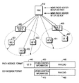
図10を参照すれば、RNC510は同じセルに位置しており、Cell_FACH状態にあるUE1521、UE2522及びUE3523にFACH及びCCCHを用いてMBMS RADIO BEARER SETUPメッセージを伝送する。この際、FACH及びCCCHを通じて伝送されるMBMS RADIO BEARER SETUPメッセージのフォーマットは図10に示した通りである。ここで、前記CCCHを通じて伝送されるMBMS RADIO BEARER SETUPメッセージのフォーマットはUEの各々を区別するためのUE識別子を含まず、ペイロード1060にはUEの各々を識別できるUE識別子が含まれる。したがって、Cell_FACH状態にあるUEは前記CCCHを通じてMBMS RADIO BEARER SETUPメッセージを受信し、前記UEの各々はCCCHを通じて受信したMBMS RADIO BEARER SETUPメッセージを直接にRRC階層へ伝送する。前記RRC階層は前記MBMS RADIO BEARER SETUPメッセージがUEの自分のメッセージであるかを判断する。一方、本発明の第3実施形態では前記CCCHを通じてMBMS RADIO BEARER SETUPメッセージなどのような共通制御情報を多数のUEに伝送する。前記共通制御情報はUE識別子としてM−RNTI(MBMS−Radio Network Temporary Identifier)を使用する。
【0062】
図10を参照すれば、セル2530にはCell_FACH状態のUE4531及びCell_DCH状態のUE5532が存在し、CCCHとFACH539を通じてUE531に対する制御メッセージが伝送され、DCH538を通じてUE5532に対する制御メッセージが伝送される。さらに、Cell_FACH状態のUE4531はFACHを通じて受信されるすべてのトランスポートブロック(TB:Transport Block)を処理してMAC階層へ伝え、前記MAC階層は前記TBのヘッダー部分のターゲットチャンネルタイプフィールド(TCTF:Target Channel Type Field)1050を用いて前記受信したTBをUE識別子判読部620又はRRCと連結されている無線リンク制御(RLC)階層へ伝えるかを判断する。ここで、前記TCTF1050はFACHを通じて伝送されるすべてのTBに付加されるフィールドであり、該当TBのチャンネルタイプを示す情報を含む。例えば、前記TCTF1050が“11”でコーディングされる場合、前記TBは専用トラフィックチャンネル(DTCH:Dedicated Traffic Channel)又は専用制御チャンネル(DCCH:Dedicated Control Channel)に属する。前記TCTF1050に連続するフィールド、すなわち、ペイロード1060にはUE識別子情報と多重化情報が含まれる。したがって、本発明の第1実施形態及び第2実施形態の他の制御情報470,570の前部分には実際では“11”でコーディングされたTCTFフィールドが存在するが、図示及び説明は省略する。
【0063】
一方、前記TCTF1050が“01000000”でコーディングされていると、受信したTBはCCCHを通じて伝送されたデータを示す。したがって、受信側のMAC階層は該当TBをRRCと連結されているRLC階層へ伝える。前記RRC階層はRLC階層から前記CCCHを通じて伝送されたTBのペイロード1060フィールドに含まれているUE識別子情報を解釈して前記TBがUE自分のTBであるかを判断する。図11を参照してUMTS通信システムのUEとUTRANとの間に構成されるプロトコルスタック(Protocol stack)を説明する。
【0064】
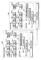
図11は本発明の実施形態における機能を行うUMTS通信システムのプロトコルスタックを概略的に示した図である。
【0065】
図11を参照すれば、送信側1500がUTRAN、受信側1550がUEである場合(すなわち、順方向通信の場合)、前記プロトコル構造は順方向通信及び逆方向通信の両方に適用されることができる。前記UE1550とUTRAN1500との間には前記UE1550が初めにパワーオンとされた後、RRC連結セットアップ(以下、“RRC CONNNECTION SETUP”と称する)過程などを通じてCCCH、DCCH及びDTCHなどが構成されている。ここで、前記CCCHとDCCHはRRCメッセージをやり取りする通路であり、DTCHはUE1550とUTRAN1500との使用者データを送受信するチャンネルである。前記CCCHは前記UTRAN1500とUE1550との間に一つのみが構成されるが、DCCHとDTCHは多数個で構成されうる。前記DCCH、DTCH及びCCCHを論理チャンネルと称する。前記論理チャンネルには一つ又は二つのRLC階層が構成されうる。ここでは、説明の便宜上、一つの論理チャンネルに一つのRLC階層が構成される場合を仮定する。送信側、すなわち、UTRAN1500のRLC階層1520−1〜1520−Nは前記RLC階層1520−1〜1520−Nに連結されている上位階層、すなわち、RRC階層1510−1〜1510−3とアプリケーション階層1510−Nから伝えられるデータを適宜のサイズにセグメントし、前記セグメントデータに一連番号のような付加情報を与える。
【0066】
さらに、受信側、すなわち、UE1550のRLC階層1560−1〜1560−NはMAC階層1570から伝えられるデータの一連番号などを参照してセグメント伝送データを組立てて前記RLC階層1560−1〜1560−Nに連結された上位階層、すなわち、RRC階層1590−1〜1590−3とアプリケーション階層1590−Nへ伝える。一方、前記UTRAN1500のMAC階層1530は多重化情報を挿入する。前記MAC階層1530の多重化情報挿入部1530−1はDTCH又はDCCHを通じて伝えられるデータに該当論理チャンネルの識別子を挿入する。これとは異なり、前記CCCHには多重化情報が挿入されない。したがって、UE1550のMAC階層1570の多重化情報判読部1570−1は前記UTRAN1500のMAC階層1530の多重化情報挿入部1530−1で挿入した論理チャンネル識別子を判読し、前記判読論理チャンネル識別子を用いて受信したデータを該当RLC階層へ伝える。
【0067】
さらに、前記UTRAN1500のMAC階層1530のUE識別子挿入部1530−2は前記多重化情報挿入部1530−1から伝えられたデータに前記データを受信する受信側の識別子を挿入する。ここで、前記UE識別子挿入部1530−2は、上述した本発明の実施形態に応じて相違した識別子を受信側の識別子に挿入するが、第1実施形態ではUE識別子、第2実施形態ではRNCサービス識別子が挿入され、第3実施形態では前記RRC階層で前記RNCサービス識別子が挿入される。上述したように本発明の第1実施形態及び第2実施形態では前記MAC階層1530に位置している多重化情報挿入部1530−1で多重化情報が挿入されるが、本発明の第3実施形態では前記MAC階層1530の前記多重化情報挿入部1530−1の動作が行われない。本発明の第3実施形態で前記MAC階層1530の多重化情報挿入部1530−1の動作が行われない理由は前記CCCHの場合、多重化情報が挿入されないからである。但し、本発明の第1実施形態、第2実施形態及び第3実施形態で前記MAC階層1530の前記TCTF挿入部1530−3のTCTFの挿入動作は行われる。したがって、本発明の第1実施形態及び第2実施形態の受信側の場合、UE1550のMAC階層1570は前記挿入されたRNCサービス識別子を判読することにより、MBMSサービスを受信するUEを識別する。さらに、本発明の第3実施形態ではUE1550のRRC階層1590−1〜1590−N−1は前記挿入されたRNCサービス識別子を判読する。より詳しくは、UE1550のMAC階層1570のUE識別子判読部1570−2は物理階層1560又はTCTF判読部1570−3から伝えられたデータのUE識別子が自分のUE識別子と同じであるかを検査する。その検査結果、前記物理階層1560又はTCTF判読部1570−3から伝えられたデータのUE識別子とUEの自分の識別子が同じである場合、前記UE識別子判読部1570−2は前記データのUE識別子を多重化情報判読部1570−3へ伝える。
【0068】
さらに、前記UTRAN1500のMAC階層1530のTCTF挿入部1530−3はRLC階層1520−1又はUE識別子挿入部1530−2から伝えられるデータにTCTFを挿入する。ここで、CCCHを通じて伝えられるデータは、上述したように前記多重化情報挿入部1530−1とUE識別子挿入部1530−2を通らず、前記RLC階層1520−1からTCTF挿入部1530−3へ直接入力される。前記TCTF挿入部1530−3は前記CCCHを通じて伝えられるデータには“01000000”のTCTFをコーディングする。一方、DCCH又はDTCHを通じて伝えられるデータは前記多重化情報挿入部1530−1とUE識別子挿入部1530−2を通じて前記TCTF挿入部1530−3へ伝えられ、前記TCTF挿入部1530−3は前記DCCH又はDTCHを通じて伝えられるデータには“11”のTCTFをコーディングする。ここで、UE1550のMAC階層1570のTCTF判読部1570−3は物理階層1560からの受信データの最初の2ビットが01である場合、残り6ビットを取り除き、すなわち“01000000”を取り除いた後、CCCHと連結されたRLC階層1590−1へ伝える。さらに、前記TCTF判読部1570−3は受信データの最初の2ビットが11である場合、11を取り除いて前記UE識別子判読部1570−2へ伝える。
【0069】
ここで、前記TCTF判読部1570−3、TCTF挿入部1530−3、UE識別子判読部1570−2及びUE識別子挿入部1530−2は順方向の場合、FACHを通じて伝送され、受信される論理チャンネルのみに対して構成される。すなわち、任意のDTCHxが専用物理チャンネル(DPCH:Dedicated Physical Channel)を通じて伝送されると、前記論理チャンネルDTCHxに対しては前記TCTF判読部1570−3、TCTF挿入部1530−3、UE識別子判読部1570−2及びUE識別子挿入部1530−2は構成されない。さらに、RLC階層で適宜のサイズにセグメントされて付加情報が挿入された後、MAC階層で付加情報が挿入されて物理階層へ伝えられるデータをTBという。上位階層、例えば、RRC階層から伝えられた500ビットのデータがRLC階層で五つの100ビットのデータにセグメントされた後、前記五つの100ビットのデータの各々に16ビットのRLC付加情報と8ビットのMAC付加情報が挿入されると、MAC階層は物理階層へ五つの124ビットのデータを伝えるが、この124ビットのデータの各々がTBとなる。
【0070】
ここで、本発明の第3実施形態を図11に参照してより詳しく説明すると、次の通りである。
【0071】
図11を参照すれば、任意のMBMSサービスに対する共通情報を伝送しようとするUTRAN1500は前記MBMSサービスに対する共通情報を含むメッセージ、例えば、MBMS RADIO BEARER SETUPメッセージ又はMBMS無線ベアラー解除(以下、“MBMS RADIO BEARER RELEASE”と称する)メッセージを構成する。この際、前記MBMS RADIO BEARER SETUPメッセージ又はMBMS RADIO BEARER RELEASEメッセージにはUE識別子情報の代わりにRNCサービス識別子情報を挿入する。前記MBMS RADIO BEARER SETUPメッセージ又はMBMS RADIO BEARER RELEASEメッセージはRLC階層1520−1へ伝えられ、前記RLC階層1520−1は前記MBMS RADIO BEARER SETUPメッセージ又はMBMS RADIO BEARER RELEASEメッセージに含まれているデータを所定のサイズにセグメントした後、MAC階層1530のTCTF挿入部1530へ伝える。ここで、前記MBMS RADIO BEARER SETUPメッセージ又はMBMS RADIO BEARER RELEASEメッセージが前記RLC階層1520−1へ伝えられる理由は、前記MBMS RADIO BEARER SETUPメッセージ又はMBMS RADIO BEARER RELEASEメッセージがCCCHを通じて伝えられるからである。さらに、前記MBMS RADIO BEARER SETUPメッセージ又はMBMS RADIO BEARER RELEASEメッセージはCCCHを通じて伝送されるため、前記メッセージは前記RLC階層1520−1から前記MAC階層1530の多重化情報挿入部1530−1及びUE識別子挿入部1530−2の特定動作を行わず、前記セグメントデータを前記MAC階層のTCTF挿入部1530−3に出力する。
【0072】
前記TCTF挿入部1530−3は前記RLC階層1520−1からの出力データに“01000000”でコーディングされたTCTFを挿入した後、Cell_FACH状態にあるUEが位置するセルの物理階層1540へ伝える。前記TCTF挿入部1530−3の動作は本発明の第1実施形態、第2実施形態で動作する場合又は第3実施形態で動作する場合のいずれにも適用される。前記TCTF挿入部1530−3から出力されるデータがTBとなる。前記物理階層1540は前記TCTF挿入部1530−3からのTBをチャンネルコーディング、拡散及び変調などの一連の送信信号処理過程を行った後、FACHを通じて伝送する。ここで、Cell_FACH状態にあるUE1550の物理階層1560は前記FACHを通じて伝えられるTBをMAC階層1570へ伝える。前記MAC階層1570は前記物理階層1560からのTBをTCTF判読部1570−3に出力し、前記TCTF判読部1570−3は前記TBのTCTFを判読して“01000000”でコーディングされている場合、RLC階層1560−1へ伝える。ここで、前記TCTF判読部1570−3が前記TBのTCTFが“01000000”でコーディングされている場合、前記TBをRLC階層1560−1へ伝える理由は、前記TBがCCCHを通じて伝送されるからである。
【0073】
前記RLC階層1560−1は前記TCTF判読部1570−3からのTBの一連番号などの付加情報を用いてもとのメッセージ、すなわち、MBMS RADIO BEARER SETUPメッセージ又はMBMS RADIO BEARER RELEASEメッセージに組立てた後、該当RRC階層1590−1へ伝える。前記RRC階層1590−1は前記MBMS RADIO BEARER SETUPメッセージ又はMBMS RADIO BEARER RELEASEメッセージがCCCHを通じて伝送されるメッセージなので、前記MBMS RADIO BEARER SETUPメッセージ又はMBMS RADIO BEARER RELEASEメッセージに含まれているRNC識別子情報を検査する。すなわち、CCCHを通じて伝送される場合、前記送信側のRRC階層で挿入されたRNCサービス識別子を前記RRC階層1590−1で判読する。本発明ではUE識別子の代わりにRNCサービス識別子が含まれるため、前記RNCサービス識別子が図3のステップ306で受信したRNCサービス識別子と同じであるかを検査する。その結果、前記MBMS RADIO BEARER SETUPメッセージ又はMBMS RADIO BEARER RELEASEメッセージに含まれているRNCサービス識別子がステップ306で受信したRNCサービス識別子と同じである場合、前記MBMS RADIO BEARER SETUPメッセージ又はMBMS RADIO BEARER RELEASEメッセージに含まれている情報に基づいて必要動作を行う。ここで、前記必要動作はメッセージ種類に応じて異なる。例えば、前記受信したメッセージがMBMS RADIO BEARER SETUPメッセージである場合、前記RRC階層1590−1は前記MBMS RADIO BEARER SETUPメッセージに含まれているMBMS無線チャンネル関連情報を用いて該当物理階層などを構成する。すなわち、前記RRC階層1590−1は物理階層の逆拡散器をMBMSチャンネルに適用する拡散コードに適合するように構成し、復調器をMBMSチャンネルに適用する変調方式に適合するように構成し、チャンネルデコーダをMBMSチャンネルに使用するチャンネルコーディングパラメータに適合するように構成する。これとは異なり、前記受信メッセージがMBMS RADIO BEARER RELEASEメッセージである場合、RRC階層1590−1は物理階層にMBMSチャンネルによる受信を中止することを命令する。
【0074】
ここで、前記MBMS RADIO BEARER SETUPメッセージ又はMBMS RADIO BEARER RELEASEメッセージには次のような情報が含まれる。
(1)メッセージタイプ:該当メッセージの種類を示す情報であり、任意の整数値として予め決定されている。
(2)UE識別子情報:メッセージを受信するUEの識別子を示し、本発明の第3実施形態ではUE識別子情報としてRNCサービス識別子が使用され、16ビット又は32ビットのビットストリームからなる。
(3)その他の制御情報:メッセージタイプに応じて適宜の情報を備え、MBMS RADIO BEARER SETUPメッセージにはMBMSサービスによるチャンネル関連情報を含み、MBMS RADIO BEARER RELEASEメッセージ情報にはMBMSサービスの中止時間情報などを含むことができる。
【0075】
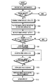
図12を参照して本発明の第3実施形態を支援するUE動作を説明する。
【0076】
図12は本発明の第3実施形態によるUE動作過程を示したフローチャートである。説明の便宜上、MBMS RADIO BEARER SETUPメッセージの受信場合のみに対して説明し、本発明の第1実施形態及び第2実施形態と同じ過程に対しては図7と同じ参照符号を使用する。
【0077】
まず、ステップ701でメニュー情報を受信したUEはステップ702へ進行する。ステップ702で前記UEは特定のMBMSに対するサービス受信を望む場合はステップ703へ進行する。ステップ703で前記UEは前記特定のMBMSサービス受信を要求するMBMS SERVICE REQUEST 1メッセージを送信し、ステップ1204へ進行する。ここで、前記MBMS SERVICE REQUEST 1メッセージには前記サービス受信を望む特定のMBMSを示すBM−SCサービス識別子が含まれる。ステップ1204で前記UEはその状態に応じて適宜なチャンネルを監視する。すなわち、Cell_FACH状態ではFACHを、Cell_DCH状態ではDCHを監視する。該当チャンネルを監視するとき、該当チャンネルを通じてMBMS SERVICERESPONSE 1メッセージが受信されると、前記UEは、すなわち、前記UEのRRC階層は前記MBMS SERVICE RESPONSE 1メッセージに含まれているRNCサービス識別子を貯蔵し、ステップ705へ進行する。ステップ705でUEはその状態に応じて適宜なチャンネルを監視し、RNCからMBMS SERVICE NOTIFY 1メッセージを受信し、前記受信したMBMS SERVICE NOTIFY 1メッセージに含まれているサービス識別子情報を検出し、ステップ706へ進行する。ステップ706で前記UEは前記MBMS SERVICE NOTIFY 1メッセージから検出されたサービス識別子情報を用いて該当MBMSサービスを受信するかを再び確認する。その確認結果、該当MBMSサービス受信を決定すると、前記UEはステップ707へ進行する。ステップ707で前記UEは前記RNCへMBMS SERVICE NOTIFY RESPONSE 1メッセージを送信し、ステップ1208へ進行する。
【0078】
ステップ1208で前記UEはその状態に応じてチャンネルを監視し、前記RNCからMBMS RADIO BEARER SETUPメッセージを受信し、ステップ1209へ進行する。ステップ1209で前記UE、すなわち、UEのMAC階層は該当チャンネル、すなわち、FACHを通じて受信したTBのTCTFを検査してTCTFが“01000000”であるTBをRLC階層へ伝え、RLC階層は前記MAC階層から受信したTBを一つのメッセージとして構成した後、RRC階層へ伝える。前記RRC階層は前記RLC階層からのメッセージのメッセージ種類情報を用いて前記メッセージがMBMS無線ベアラーセットアップ情報を含むことを感知し、ステップ1209へ進行する。ステップ1209で前記UEは前記MBMS RADIO BEARER SETUPメッセージがCCCHを通じて伝えられるので、前記MBMS RADIO BEARER SETUPメッセージに含まれているUE識別子情報を検査する。その検査結果、前記UE識別子情報にRNCサービス識別子がコーディングされていると、前記UEのRRC階層は前記MBMS RADIO BEARER SETUPメッセージに含まれているMBMSチャンネル関連情報を用いて物理階層を構成し、ステップ1210へ進行する。一方、ステップ1209の検査結果、前記UE識別子情報にRNCサービス識別子及び自分のUE識別子のうち、いずれもコーディングされない場合、前記UEのRRC階層は再び前記RLC階層からデータの伝送を待機する。さらに、ステップ1209でUE識別子情報にメッセージを受信したUEのUE識別子がコーディングされていると、前記MBMS RADIO BEARER SETUPメッセージに含まれている情報を用いて適宜の動作を行う。このようにUE識別子情報にUE自分の識別子がコーディングされている場合は本発明の実施形態とは関連がないため、ここではその詳細な説明を省略する。
【0079】
ステップ1211で前記UEは前記MBMS RADIO BEARER SETUPメッセージに相応する動作実行の完了を示すMBMS RADIO BEARER SETUP COMPLETETメッセージを前記RNCへ送信し、ステップ1212へ進行する。ステップ1212で前記UEは前記MBMS RADIO BEARER SETUPメッセージに含まれているサービス開始時間に該当MBMSストリームの受信を開始する。
【0080】
図13を参照して本発明の第3実施形態における機能を行うためのUTRAN、すなわち、RNCの動作過程を説明する。
【0081】
図13は本発明の第3実施形態によるUTRANの動作過程を示したフローチャートである。説明の便宜上、本発明の第1実施形態及び第2実施形態と同じ過程に対しては図9と同じ参照符号を使用する。
【0082】
まず、ステップ901でRNCはUEからMBMS SERVICE REQUEST 1メッセージを受信し、ステップ902へ進行する。ステップ902で前記RNCは前記MBMSSERVICE REQUEST 1メッセージに含まれているBM−SCサービス識別子に該当するRNC SERVICE CONTEXTが既に存在するかを検査する。その検査結果、前記BM−SCサービス識別子に該当するRNC SERVICE CONTEXTが存在しない場合、前記RNCはステップ903へ進行する。ステップ903で前記RNCは前記BM−SCサービス識別子に該当する新たなRNC SERVICE CONTEXTを生成し、ステップ904へ進行する。ステップ902の検査結果、前記BM−SCサービス識別子に該当するRNC SERVICE CONTEXTが既に存在する場合、前記RNCはステップ904へ進行する。ステップ904で前記RNCは前記RNC SERVICE CONTEXTに前記MBMS SERVICE REQUEST 1メッセージを伝送したUEを示すUE識別子と、前記UEが位置しているセルを示すセル識別子とを追加して更新した後、ステップ905へ進行する。
【0083】
ステップ905で前記RNCは前記SGSNへ前記UE識別子を含むMBMS SERVICE REQUEST 2メッセージを送信し、ステップ906へ進行する。前記SGSNは前記MBMS SERVICE REQUEST 2メッセージを用いてMBMSサービスを受けようとするUEと前記UEを管理するRNCとを把握することができる。ステップ906で前記RNCは前記SGSNから前記MBMS SERVICE REQUEST 2メッセージに相応するMBMS SERVICE RESPONSE 2メッセージを受信し、ステップ1407へ進行する。ステップ1407で前記RNCはRNCサービス識別子を決定し、RNC SERVICE CONTEXTに追加した後、ステップ908へ進行する。ここで、前記RNCサービス識別子は他のMBMSサービスに割当てられないRNCサービス識別子のうち、一つとして選択されうる。さらに、ステップ902でRNC SERVICE CONTEXTが既に存在すると、RNCサービス識別子も既に割当てられているため、RNCサービス識別子を再び割当てる必要はない。
【0084】
ステップ908で前記RNCはRNCサービス識別子を含むMBMS SERVICE RESPONSE 1メッセージを前記UEへ送信し、ステップ909へ進行する。ステップ909で前記RNCはSGSNからMBMS SERVICE NOTIFY 2メッセージを受信し、ステップ910へ進行する。ステップ910で前記RNCは該当RNC SERVICE CONTEXTに登録されているUEにMBMS SERVICE NOTIFY 1メッセージを伝送し、ステップ911へ進行する。ステップ911で前記RNCは前記該当UEから前記MBMS SERVICE NOTIFY 1メッセージに相応するMBMS SERVICE NOTIFY RESPONSE 1メッセージを受信し、ステップ912へ進行する。ステップ912で前記RNCは前記MBMS SERVICE NOTIFY RESPONSE 1メッセージを送信したUEの各々のUE識別子と前記UEの属するセルの識別子とをRNC SERVICE CONTEXTに更新し、ステップ913へ進行する。
【0085】
ステップ913で前記RNCはMBMS SERVICE NOTIFY RESPONSE 2メッセージを前記SGSNへ伝送し、ステップ914へ進行する。ステップ914で前記RNCは前記SGSNからMBMS RADIO BEARER ASSIGNMENT REQUESTメッセージを受信し、ステップ915へ進行する。ステップ915で前記RNCは前記MBMS RADIOBEARER ASSIGNMENT REQUESTメッセージの受信により前記MBMS RADIO BEARER ASSIGNMENT REQUESTメッセージに含まれているQoS情報に基づいて無線チャンネル設定を準備する。すなわち、前記RNCは前記RNC SERVICE CONTEXTに登録されているセルを管理するNode BへMBMS RADIO LINK SETUP REQUESTメッセージを伝送し、ステップ916へ進行する。ここで、前記MBMS RADIO LINK SETUP REQUESTメッセージにはMBMSサービスを提供する、すなわち、MBMSストリームが伝送される無線チャンネルに対する情報が含まれ、前記MBMS RADIO LINK SETUP REQUESTメッセージを受信した該当Node Bは前記MBMS RADIO LINK SETUP REQUESTメッセージに含まれている無線チャンネル関連情報を用いて送信部810又は物理階層1540を構成する。前記送信部810の構成が完了されると、前記該当Node Bは前記RNCへMBMS RADIO LINK SETUP RESPONSEメッセージを伝送する。前記RNCはステップ916で前記Node Bが伝送したMBMS RADIO LINK SETUP RESPONSEメッセージを受信し、ステップ1417及びステップ918へ進行する。ステップ1417で前記RNCは前記MBMS RADIO LINK SETUP RESPONSEメッセージを通じて送信部810又は物理階層1540の構成完了を通告するNode Bに属するUEへFACHとCCCHを通じてMBMS RADIO BEARER SETUPメッセージを伝送し、ステップ919へ進行する。ここで、前記UEがCell_FACH状態にある場合はステップ1417のようにFACHとCCCHを通じて伝送され、すべてのUEに対して一つのみのメッセージが伝送される。上述したように、前記MBMS RADIO BEARER SETUPメッセージのUE識別子情報フィールドにはRNCサービス識別子がコーディングされ、前記MBMS RADIO BEARER SETUPメッセージはRLC階層1520−1とTCTF挿入部1530−3を通じてFACHとCCCHを通じて伝送される。一方、前記UEが前記Cell_FACH状態でないCell_DCH状態にある場合、前記RNCはステップ918へ進行してDCHを通じて前記MBMS RADIO BEARER SETUPメッセージを伝送し、ステップ919へ進行する。
【0086】
ステップ919で前記RNCは該当UEからMBMSRADIO BEARER SETUP COMPLETEメッセージを受信し、ステップ920へ進行する。ステップ920で前記RNCは前記MBMSデータ伝送のための無線チャンネル構成完了を示すMBMS RAB ASSIGNMENT RESPONSEメッセージを用いてSGSNに通告し、ステップ921へ進行する。ステップ921で前記RNCはMBMSストリームをSGSNから受信し、ステップ922で前記RNCは前記構成されている無線チャンネルを通じてMBMSデータ、すなわち、MBMSストリームを伝送する。
【0087】
【発明の効果】
上述したように、本発明は移動通信システムでMBMSサービスの提供時に同じMBMSサービスを要請したUEに該当する無線チャンネル構成情報を共通チャンネルを通じて伝送することにより、前記無線チャンネル構成情報送受信によるメッセージ送受信過程のロード(load)を取り除く。さらに、本発明はMBMSサービスの提供時に同じMBMSサービスを要請したUEに該当無線チャンネル構成情報を同じメッセージに識別子のみを相違にして伝送することにより、前記無線チャンネル構成情報送受信によるメッセージ送受信過程のロードを取り除くことができる。
【0088】
本発明の詳細な説明では具体的な実施形態について説明したが、本発明の範囲を逸脱しない限り、各種の変形が可能なのは明らかである。したがって、本発明の範囲は前記実施形態に限るものでなく、特許請求の範囲のみならず、その範囲と均等なものにより定められるべきである。
【図面の簡単な説明】
【図1】移動通信システムでMBMSサービスを提供するためのネットワーク構造を概略的に示した図である。
【図2】移動通信システムでMBMSサービスを開始するための過程を示した信号流れ図である。
【図3】本発明の実施形態によるMBMSサービス提供過程を示した信号流れ図である。
【図4】本発明の第1実施形態によるMBMSサービスのための無線チャンネル構成情報伝送を概略的に示した図である。
【図5】本発明の第2実施形態によるMBMSサービスのための無線チャンネル構成情報伝送を概略的に示した図である。
【図6】本発明の実施形態における機能を行うためのUE構造を示した図である。
【図7】図6のUE動作過程を示したフローチャートである。
【図8】本発明の実施形態における機能を行うためのUTRAN構造を示した図である。
【図9】図8のUTRAN動作過程を示したフローチャートである。
【図10】本発明の第3実施形態によるCCCHを通じたMBMSサービスのための無線チャンネル構成情報伝送を概略的に示した図である。
【図11】本発明の実施形態における機能を行うUMTS通信システムのプロトコル構造を概略的に示した図である。
【図12】本発明の第3実施形態によるUE動作過程を示したフローチャートである。
【図13】本発明の第3実施形態によるUTRANの動作過程を示したフローチャートである。
【符号の説明】
410 RNC
421,422,423,431,432 UE
440 UE識別子情報
450,470 その他の制御情報
460,480 ペイロード
510 RNC
521,522,523,531,532 UE
530 セル
540 RNC識別子情報
550,570 その他の制御情報
560,580 ペイロード
600 アンテナ
610 受信部
620 UE識別子判読部
630 逆多重化器
640−1〜640−n 無線資源制御(RRC)階層
800 アンテナ
810 送信部
820 UE識別子挿入部
830 多重化器
840−1,…,840−n 上位階層
1050 ターゲットチャンネルタイプフィールド(TCTF)
1060 ペイロード
1500 UTRAN(送信側)
1510−1〜1510−3 RRC階層
1510−N アプリケーション階層
1520−1〜1520−N RLC階層
1530 MAC階層
1530−1 多重化情報挿入部
1530−2 UE識別子挿入部
1530−3 TCTF挿入部
1540 物理階層
1550 UE(受信側)
1560−1〜1560−N RLC階層
1570 MAC階層
1570−1 多重化情報判読部
1570−2 UE識別子判読部
1570−3 TCTF判読部
1580 物理階層
1590−1〜1590−N−1 RRC階層
1590−N アプリケーション階層[0001]
TECHNICAL FIELD OF THE INVENTION
The present invention relates to a mobile communication system, and more particularly, to an apparatus and method for transmitting configuration information of a wireless channel for providing a multimedia broadcast / multicast service (MBMS) through a common channel.
[0002]
[Prior art]
2. Description of the Related Art With the development of the communication industry, a code division multiple access (CDMA) mobile communication system provides not only a voice service but also a multimedia multicast service for transmitting a large amount of data such as packet data and circuit data. I have. In order to support the multimedia multicast communication, a broadcast / multicast service, which provides a service from a single data source to a plurality of user terminals (UEs), has been introduced. The broadcast / multicast service is a cell broadcast service (CBS), which is a message-based service, and a multimedia broadcast / multicast service that supports multimedia data such as real-time video / audio, still video, and text. (MBMS).
[0003]
Here, a network structure for providing the MBMS in a mobile communication system will be described with reference to FIG. The MBMS can have multiple types, each of which is defined as a “service”. Therefore, the MBMS has multiple MBMS services.
[0004]
FIG. 1 is a diagram schematically illustrating a network structure for providing an MBMS service in a mobile communication system. Referring to FIG. 1, a Broadcast / Multicast-Service Center (BM-SC) 110 is a source that provides an MBMS stream, and the BM-SC 110 schedules a stream for an MBMS service and transmits the MBMS service. (N / W) 111. The
[0005]
As shown in FIG. 1, only one radio channel is provided between one Node B 1102 and UEs 1104, UE 1105, and UE 1106 belonging to the Node B 1102 to provide an MBMS service. Further, although not shown in FIG. 1, a Home Location Register (HLR) is connected to the SGSN 100 to perform subscriber authentication for the MBMS service.
[0006]
FIG. 2 is a signal flow diagram illustrating a process for starting an MBMS service in a mobile communication system. Referring to FIG. 2, the BM-SC 110 notifies menu information on an available MBMS service to a UE that is a subscriber of the MBMS service (step 201). The BM-SC 110 may broadcast the menu information to a predetermined service area or transmit the menu information only to UEs requesting an MBMS service. Through the menu information, the BM-SC 110 notifies an MBMS service identifier for distinguishing each MBMS service. For convenience of description, it is assumed that the MBMS service subscriber is UE 104. The UE 104 that has received the menu information selects a specific MBMS service from the menu information, and transmits a service request (SERVICE JOING) message for the selected MBMS service to the BM-SC 110. Here, in the request for the MBMS service, a service identifier to be received by the UE is selected from among the MBMS service identifiers according to the menu information, and information of the UE requesting the MBMS service is transmitted together. The service request is transmitted from the UE 104 to the BM-SC 110 via the NodeB 102, the RNC 101, the SGSN 100, and the
[0007]
After the request and response for the specific MBMS service are completed, the BM-SC 110 transmits a service announcement (SERVICEANNOUNCEMENT) message indicating the near start of the specific MBMS service to the UE 104 (step 203). In FIG. 2, it is assumed that the UE that intends to receive a specific MBMS service is the UE 104, that is, only one UE exists. However, as described above, the network configuration, that is, the BM- The
[0008]
The UE 104 that has received the service guidance message transmits a service confirmation (SERVICE CONFIRM) message to the BM-SC 110 to confirm that the UE 104 intends to receive the specific MBMS service (Step 204). The service confirmation message is also transmitted to the BM-SC 110 through the
[0009]
As described above, providing a MBMS service requires a lot of control information, and transmitting this control information to each of the UEs requires a number of message transmission / reception processes. Therefore, in providing the MBMS service, a scheme for transmitting control information, for example, control information such as radio channel configuration information, to a plurality of UEs through one control message is required.
[0010]
[Problems to be solved by the invention]
Accordingly, an object of the present invention is to provide an apparatus and a method for transmitting control information in common for each MBMS service to a UE receiving the MBMS service in a mobile communication system.
[0011]
Another object of the present invention is to provide an apparatus and method for transmitting radio channel configuration information to a UE receiving the same MBMS service in a mobile communication system through a common channel.
[0012]
It is another object of the present invention to provide an apparatus and method for transmitting radio channel configuration information to a UE receiving the same MBMS service through a common control channel in a mobile communication system.
[0013]
It is still another object of the present invention to provide an apparatus and method for transmitting common control information to a UE receiving the same MBMS service in a mobile communication system through a media access control (MAC) message.
[0014]
[Means for Solving the Problems]
According to an aspect of the present invention, there is provided at least one method for transmitting the MBMS-related control information in a mobile communication system providing a multimedia broadcast / multicast service (MBMS) having a plurality of services. Receiving a service provision request for a specific MBMS service among the plurality of services from one user terminal (UE), allocating a service identifier (ID) for the specific MBMS service, and allocating the service identifier; Transmitting a medium access control (MAC) message including the service identifier and the specific MBMS service-related control information to the at least one user terminal.
[0015]
According to another aspect of the present invention, a method for receiving the MBMS-related control information in a mobile communication system providing a multimedia broadcast / multicast service (MBMS) having a plurality of services is provided. Receiving a service identifier (ID) for the specific MBMS service after requesting service provision for a specific MBMS service, and receiving a service identifier for the specific MBMS service through a common channel Receiving a medium access control (MAC) message including a service identifier and control information for the MBMS service; and if the service identifier included in the medium access control message matches the service identifier for the specific MBMS service, M Characterized in that it comprises a step of performing a control operation corresponding to the MS control information.
[0016]
According to still another aspect of the present invention, an apparatus for transmitting the MBMS-related control information in a mobile communication system providing a multimedia broadcast / multicast service (MBMS) having a plurality of services includes at least: When receiving a service provision request for a specific MBMS service among the plurality of services from one user terminal (UE), a controller allocating a service identifier (ID) for the specific MBMS service; A medium access control (MAC) message generator for generating a medium access control message including the specific MBMS service related control information.
[0017]
According to still another aspect of the present invention, there is provided an apparatus for receiving the MBMS-related control information in a mobile communication system providing a multimedia broadcast / multicast service (MBMS) having a plurality of services, A media access control (MAC) message including a service identifier for the specific MBMS service in response to a service provision request for the specific MBMS service among the plurality of services, and including a service identifier and control information for the MBMS service through a common channel. And a service identifier reader performing a control operation corresponding to the MBMS control information when a service identifier included in the medium connection control message matches a service identifier for the specific MBMS service. Including The features.
[0018]
BEST MODE FOR CARRYING OUT THE INVENTION
Hereinafter, preferred embodiments of the present invention will be described in detail with reference to the accompanying drawings. In the following description, detailed descriptions of well-known functions and structures are omitted so as to make only the gist of the present invention clear.
[0019]
FIG. 3 is a signal flowchart illustrating an MBMS service providing process according to an embodiment of the present invention.
[0020]
Before describing the signal flow of FIG. 3, it is assumed that the structure of the mobile communication system is the same as that of the prior art mobile communication system shown in FIG. Further, the RNC SERVICE CONTEXT managed by the radio network controller (RNC) 101 and the SGSN SERVICE CONTEXT managed by the service packet radio service support node (SGSN) 100 will be described. The
The information included in the RNC SERVICE CONTEXT and SGSN SERVICE CONTEXT will be specifically described.
First, the information included in the RNC SERVICE CONTEXT is as follows.
RNC SERVICE CONTEXT = {BM-SC Service Identifier, RNC Service Identifier, Identifier of Cell Receiving or Receiving MBMS Service, Identifier of UE Located in Corresponding Cell, Qos Required to Provide MBMS Service}
[0021]
As described above, one RNC SERVICE CONTEXT includes a service identifier, multiple cell identifiers, and multiple UE identifier information. Further, the service identifier includes a BM-SC service identifier and an RNC service identifier. The BM-SC service identifier is a unique identifier given to each MBMS provided by the BM-
Second, the information included in the SGSN SERVICE CONTEXT is as follows.
SGSN SERVICE CONTEXT = {BM-SC service identifier, SGSN service identifier, identifier of RNC receiving or receiving MBMS service, QoS required to provide MBMS service}
[0022]
The SGSN service identifier is an identifier given to each of the MBMS services provided by the
[0023]
Further, the RNC SERVICE CONTEXT and the SGSN SERVICE CONTEXT are continuously updated during the MBMS service providing process. The
[0024]
Referring to FIG. 3, the
[0025]
The generation and update of the RNC SERVICE CONTEXT may be performed when the MBMS SERVICE REQUEST 1 (step 301) message is received or when a second MBMS service response (hereinafter, referred to as “
More specifically, when the
[0026]
The
[0027]
After receiving the
[0028]
On the other hand, the BM-
[0029]
Upon receiving the MBMS SERVICE NOTIFY 1 message, the
[0030]
Meanwhile, the MBMS NOTIFY
[0031]
The
[0032]
Tables 1A and 1B and Tables 2A and 2B show message types for starting the MBMS service X and the operation of each component. For convenience of explanation, the names of the messages are shown as shown in the following table, but the message names can be changed.
[Table 1A]
Among the above messages, the MBMS RAB ASSIGNMENT REQUEST message, the MBMS RAB ASSIGNMENT RESPONSE message, the MBMS RADIUS LINK SETUP REQUEST message, the MBMS RADIO LINK SETUP REPORT RESPONSE message, and the MBMS RADIO SETUP REPORT UPDATE SERVICE UPDATE SERVICE Or the RAB ASSIGNMENT REQUEST message, the RAB ASSIGNMENT RESPONSE message, and the RADIO used in the current Universal Mobile Telecommunication System (UMTS) standard. INK SETUP REQUEST message, RADIO LINK SETUP RESPONSE message, is defined as a form in which a modification of the RADIO BEARER SETUP message and RADIO BEARER SETUP COMPLETE message. However, the message includes various information for the MBMS service.
[0034]
On the other hand, when there are a plurality of UEs receiving the MBMS service in the process of providing the MBMS service shown in FIG. 3, the MBMS including channelization code information and scrambling code information is transmitted to each of the plurality of UEs through an MBMS Radio Bearer SETUP message. Radio channel configuration information for receiving the service stream is transmitted. Here, there are two methods for transmitting the configuration information of the radio channel to each of the plurality of UEs. The first is a method of transmitting an MBMS Radio Bearer Setup message to each UE, and the second is a method of transmitting the same MBMS Radio Bearer Setup message to UEs belonging to one cell. The first method is to apply the method applied in general UMTS as it is, that is, to transmit the configuration information of the radio channel to each UE one-to-one, and the second method is proposed in the present invention. This is a method of transmitting configuration information of a wireless channel to be transmitted.
[0035]
A method of transmitting radio channel configuration information to a plurality of UEs through one control message will be described with reference to FIGS.
[0036]
FIG. 4 is a diagram schematically illustrating transmission of radio channel configuration information for an MBMS service according to the first embodiment of the present invention.
[0037]
The UEs 1421, UE2422, UE3423, UE4431, and UE5432 request a first MBMS service, which is an arbitrary MBMS service, and perform steps 301 to 314 shown in FIG. 3 according to the request for the first MBMS service, that is, MBMS radio link setup. Assume that you are in a completed state. Further, the UEs 1421, UE2422, UE3423 and UE4431 are aware of FACH reception information and Random Access Channel (RACH) information, and the UEs 1421, UE2422, UE3423 and UE4431 receive messages transmitted through the FACH. It is assumed that the UE 5431 is in a state of setting the DCH (hereinafter, referred to as “Cell_DCH state”) in a state (hereinafter, referred to as “Cell_FACH state”).
[0038]
Referring to FIG. 4, the
[0039]
Meanwhile, the
[0040]
FIG. 5 is a diagram schematically illustrating transmission of radio channel configuration information for an MBMS service according to a second embodiment of the present invention.
[0041]
UEs 1521, UE2522, UE3523, UE4531, and UE5532 request a first MBMS service, which is an arbitrary MBMS service, and perform steps 301 to 314 shown in FIG. 3 according to the request for the first MBMS service, that is, MBMS radio link setup. Assume that you are in a completed state. Further, the UEs 1521, UE2522, UE3523 and UE4531 recognize the FACH reception information and the RACH information, and the UE1521, UE2522, UE3523 and UE4531 are in a Cell_FACH state for receiving a message transmitted through the FACH, and the UE5531 sets the DCH. Assume that you are in the Cell_DCH state.
[0042]
Referring to FIG. 5, the
[0043]
On the other hand, since the DCH is a channel exclusively allocated to a specific UE, the message format of the MBMS Radio Bearer Setup message transmitted through the DCH does not require separate RNC identifier information, and only the
[0044]
FIG. 6 is a diagram illustrating a UE structure for performing a function according to an embodiment of the present invention.
[0045]
Referring to FIG. 6, a radio frequency (RF) signal received through an
[0046]
The UE
[0047]
In the above description, the UE
[0048]
In the first embodiment of the present invention, the
[0049]
FIG. 7 is a flowchart illustrating a UE operation process of FIG.
Referring to FIG. 7, the UE receiving the menu information in
[0050]
FIG. 7 illustrates a case where the UE sets up a radio bearer for an MBMS service using RNC identifier information according to the second embodiment of the present invention, but as in the first embodiment of the present invention. The UE may use the UE identifier information to perform radio bearer setup for the MBMS service.
[0051]
FIG. 8 is a diagram showing a UTRAN (Universal Terrestrial Radio Access Network) structure for performing a function according to the embodiment of the present invention. Here, the UTRAN is a general term for Node B and RNC.
[0052]
Referring to FIG. 8, after receiving the
[0053]
FIG. 9 is a flowchart illustrating a UTRAN operation process of FIG.
[0054]
Referring to FIG. 9, when the RNC receives the
[0055]
In step 905, the RNC transmits an
[0056]
In
[0057]
In
[0058]
Next, a third embodiment of the present invention in which the MBMS Radio Bearer Setup message is transmitted through a common control channel (CCCH) will be described.
[0059]
FIG. 10 is a diagram schematically illustrating transmission of radio channel configuration information for an MBMS service via a CCCH according to a third embodiment of the present invention.
[0060]
Before explaining FIG. 10, the same situation described in FIG. 5, that is, UE1521, UE2522, UE3523, UE4531, and UE5532 requests the first MBMS service which is an arbitrary MBMS service, and in response to the first MBMS service request, FIG. It is assumed that steps 301 to 314 have been completed, that is, MBMS radio link setup has been completed. Further, the UEs 1521, UE2522, UE3523 and UE4531 are aware of the FACH information and the RACH information, and the UE1521, UE2522, UE3523 and UE4531 are in a Cell_FACH state for receiving a message transmitted through the FACH, and the UE5531 sets the DCH. In the Cell_DCH state.
[0061]
Referring to FIG. 10, the
[0062]
Referring to FIG. 10, a cell 2530 includes a UE 4531 in a Cell_FACH state and a UE 5532 in a Cell_DCH state. A control message for the
[0063]
On the other hand, if the
[0064]
FIG. 11 is a diagram schematically illustrating a protocol stack of a UMTS communication system performing functions according to an embodiment of the present invention.
[0065]
Referring to FIG. 11, when the transmitting
[0066]
Further, the receiving side, that is, the RLC layers 1560-1 to 1560-N of the
[0067]
Further, the UE identifier insertion unit 1530-2 of the
[0068]
Further, the TCTF insertion unit 1530-3 of the
[0069]
Here, when the TCTF reading unit 1570-3, the TCTF inserting unit 1530-3, the UE identifier reading unit 1570-2, and the UE identifier inserting unit 1530-2 are in the forward direction, only the logical channels transmitted and received through the FACH are received. Configured for That is, when an arbitrary DTCHx is transmitted through a dedicated physical channel (DPCH), the TCTF reader 1570-3, the TCTF inserter 1530-3, and the
[0070]
Here, the third embodiment of the present invention will be described in more detail with reference to FIG.
[0071]
Referring to FIG. 11, a
[0072]
The TCTF insertion unit 1530-3 inserts the TCTF coded with "01000000" into the output data from the RLC layer 1520-1, and transmits the data to the
[0073]
The RLC layer 1560-1 assembles the original message using the additional information such as the serial number of the TB from the TCTF reading unit 1570-3, that is, the MBMS Radio Bearer Setup message or the MBMS Radio Bearer Release message, Notify to the corresponding RRC layer 1590-1. Since the RRC layer 1590-1 is a message in which the MBMS Radio Bearer Setup message or the MBMS Radio Bearer Release message is transmitted through the CCCH, the RNC identifier included in the MBMS Radio Bearer Setup message or the MBMS Radio Bearer Release message is included in the MBMS Radio Bearer Setup message or the MBMS Radio Bearer Release message. I do. That is, when transmitted via the CCCH, the RNC service identifier inserted in the RRC layer of the transmitting side is read by the RRC layer 1590-1. In the present invention, since the RNC service identifier is included instead of the UE identifier, it is checked whether the RNC service identifier is the same as the RNC service identifier received in
[0074]
Here, the following information is included in the MBMS Radio Bearer Setup message or the MBMS Radio Bearer Release message.
(1) Message type: information indicating the type of the message, which is determined in advance as an arbitrary integer value.
(2) UE identifier information: An identifier of a UE that receives a message. In the third embodiment of the present invention, an RNC service identifier is used as UE identifier information, and is composed of a 16-bit or 32-bit bit stream.
(3) Other control information: appropriate information is provided according to the message type, the MBMS Radio Bearer Setup message includes channel-related information according to the MBMS service, the MBMS Radio Bearer Release message information includes suspension time information of the MBMS service, and the like. Can be included.
[0075]
A UE operation supporting the third embodiment of the present invention will be described with reference to FIG.
[0076]
FIG. 12 is a flowchart illustrating a UE operation process according to the third embodiment of the present invention. For convenience of explanation, only the case of receiving the MBMS Radio Bearer Setup message will be described, and the same reference numerals as in FIG. 7 will be used for the same processes as those of the first and second embodiments of the present invention.
[0077]
First, the UE receiving the menu information in
[0078]
In
[0079]
In
[0080]
The operation process of the UTRAN, that is, the RNC for performing the function according to the third embodiment of the present invention will be described with reference to FIG.
[0081]
FIG. 13 is a flowchart illustrating an operation process of the UTRAN according to the third embodiment of the present invention. For convenience of explanation, the same reference numerals as in FIG. 9 are used for the same processes as in the first and second embodiments of the present invention.
[0082]
First, in
[0083]
In step 905, the RNC sends an
[0084]
In
[0085]
In
[0086]
In
[0087]
【The invention's effect】
As described above, the present invention provides a message transmission / reception process by transmitting / receiving the radio channel configuration information by transmitting the radio channel configuration information corresponding to the UE requesting the same MBMS service through the common channel when providing the MBMS service in the mobile communication system. Remove the load of Furthermore, the present invention transmits the corresponding radio channel configuration information to the UE requesting the same MBMS service at the time of providing the MBMS service, with only the identifier being different from the same message, thereby loading the message transmission / reception process by transmitting / receiving the radio channel configuration information. Can be removed.
[0088]
Although the specific embodiments have been described in the detailed description of the present invention, it is apparent that various modifications can be made without departing from the scope of the present invention. Therefore, the scope of the present invention is not limited to the above embodiment, and should be defined not only by the claims but also by the equivalents of the scope.
[Brief description of the drawings]
FIG. 1 is a diagram schematically illustrating a network structure for providing an MBMS service in a mobile communication system.
FIG. 2 is a signal flow diagram illustrating a process for starting an MBMS service in a mobile communication system.
FIG. 3 is a signal flowchart illustrating an MBMS service providing process according to an embodiment of the present invention.
FIG. 4 is a diagram schematically illustrating transmission of radio channel configuration information for an MBMS service according to a first embodiment of the present invention;
FIG. 5 is a diagram schematically illustrating transmission of radio channel configuration information for an MBMS service according to a second embodiment of the present invention;
FIG. 6 is a diagram illustrating a UE structure for performing a function according to an embodiment of the present invention;
FIG. 7 is a flowchart illustrating a UE operation process of FIG. 6;
FIG. 8 is a diagram illustrating a UTRAN structure for performing a function according to an embodiment of the present invention.
FIG. 9 is a flowchart illustrating a UTRAN operation process of FIG. 8;
FIG. 10 is a diagram schematically illustrating transmission of radio channel configuration information for an MBMS service via a CCCH according to a third embodiment of the present invention;
FIG. 11 is a diagram schematically illustrating a protocol structure of a UMTS communication system performing functions according to an embodiment of the present invention.
FIG. 12 is a flowchart illustrating a UE operation process according to a third embodiment of the present invention;
FIG. 13 is a flowchart illustrating an operation process of a UTRAN according to a third embodiment of the present invention.
[Explanation of symbols]
410 RNC
421, 422, 423, 431, 432 UE
440 UE identifier information
450,470 Other control information
460,480 payload
510 RNC
521,522,523,531,532 UE
530 cells
540 RNC identifier information
550,570 Other control information
560,580 payload
600 antenna
610 Receiver
620 UE identifier reading unit
630 demultiplexer
640-1 to 640-n Radio Resource Control (RRC) Layer
800 antenna
810 Transmitter
820 UE identifier insertion unit
830 multiplexer
840-1, ..., 840-n Upper layer
1050 Target channel type field (TCTF)
1060 payload
1500 UTRAN (transmission side)
1510-1 to 1510-3 RRC layer
1510-N Application Hierarchy
1520-1 to 1520-N RLC layer
1530 MAC layer
1530-1 Multiplexed information insertion unit
1530-2 UE identifier insertion unit
1530-3 TCTF insertion part
1540 Physical Layer
1550 UE (receiving side)
1560-1 to 1560-N RLC layer
1570 MAC layer
1570-1 Multiplexed Information Reading Unit
1570-2 UE identifier reading unit
1570-3 TCTF Reading Unit
1580 Physical Layer
1590-1 to 1590-N-1 RRC layer
1590-N Application Hierarchy
Claims (20)
少なくとも一つの使用者端末機(UE:User Equipment)から前記多数のサービスのうち、特定のMBMSサービスに対するサービス提供要請を受信すると、前記特定のMBMSサービスに対するサービス識別子(ID)を割当てる過程と、
前記サービス識別子を割当てた後、前記サービス識別子及び前記特定のMBMSサービス関連制御情報を含む媒体接続制御(MAC:Medium Access Control)メッセージを前記少なくとも一つの使用者端末機へ伝送する過程と
を含むことを特徴とする方法。A method of transmitting the MBMS-related control information in a mobile communication system providing a multimedia broadcast / multicast service (MBMS) having a plurality of services,
Receiving a service provision request for a specific MBMS service among the plurality of services from at least one user terminal (UE), and allocating a service identifier (ID) for the specific MBMS service;
Allocating the service identifier and transmitting a medium access control (MAC) message including the service identifier and the specific MBMS service related control information to the at least one user terminal. The method characterized by the above.
少なくとも一つの使用者端末機(UE)から前記多数のサービスのうち、特定のMBMSサービスに対するサービス提供要請を受信すると、前記特定のMBMSサービスに対するサービス識別子(ID)を割当てる過程と、
前記サービス識別子を割当てた後、前記サービス識別子、前記特定のMBMSサービス関連制御情報を伝送するチャンネルの種類に相応するターゲットチャンネルタイプフィールド(TCTF:Target Channel Type Field)及び前記制御情報を含む媒体接続制御(MAC)メッセージを前記少なくとも一つの使用者端末機へ伝送する過程と
を含むことを特徴とする方法。A method for transmitting MBMS-related control information in a mobile communication system providing a multimedia broadcast / multicast service (MBMS) having multiple services, comprising:
Receiving a service provision request for a specific MBMS service among the plurality of services from at least one user terminal (UE), and allocating a service identifier (ID) for the specific MBMS service;
After allocating the service identifier, a target channel type field (TCTF) corresponding to a type of a channel for transmitting the specific MBMS service-related control information, and a medium connection control including the control information. Transmitting a (MAC) message to the at least one user terminal.
少なくとも一つの使用者端末機(UE)から前記多数のサービスのうち、特定のMBMSサービスに対するサービス提供要請を受信すると、前記特定のMBMSサービスに対するサービス識別子(ID)を割当てる制御器と、
前記サービス識別子及び前記特定のMBMSサービス関連制御情報を含む媒体接続制御メッセージを生成する媒体接続制御(MAC)メッセージ生成器と
を含むことを特徴とする装置。An apparatus for transmitting MBMS-related control information in a mobile communication system providing a multimedia broadcast / multicast service (MBMS) having multiple services, comprising:
A controller allocating a service identifier (ID) for the specific MBMS service when receiving a service provision request for a specific MBMS service among the plurality of services from at least one user terminal (UE);
A media access control (MAC) message generator for generating a media access control message including the service identifier and the specific MBMS service related control information.
前記制御情報を多重化する多重化器(MUX)と、
前記制御情報に前記サービス識別子を挿入するサービス識別子挿入器と
を含むことを特徴とする請求項7に記載の装置。The medium connection control message generator,
A multiplexer (MUX) for multiplexing the control information;
The apparatus of claim 7, further comprising: a service identifier inserter that inserts the service identifier into the control information.
少なくとも一つの使用者端末機(UE)から前記多数のサービスのうち、特定のMBMSサービスに対するサービス提供要請を受信すると、前記特定のMBMSサービスに対するサービス識別子を割当て、前記特定のMBMSサービス関連制御情報を伝送するチャンネルの種類に相応するターゲットチャンネルタイプフィールド(TCTF)値を決定する制御器と、
前記チャンネルの種類に相応するターゲットチャンネルタイプフィールド値、前記制御情報及び前記サービス識別子を含む媒体接続制御メッセージを生成する媒体接続制御(MAC)メッセージ生成器と
を含むことを特徴とする装置。An apparatus for transmitting MBMS-related control information in a mobile communication system providing a multimedia broadcast / multicast service (MBMS) having multiple services, comprising:
When receiving a service provision request for a specific MBMS service among the plurality of services from at least one user terminal (UE), a service identifier for the specific MBMS service is allocated, and the specific MBMS service related control information is transmitted. A controller for determining a target channel type field (TCTF) value corresponding to a type of a channel to be transmitted;
An apparatus comprising: a medium access control (MAC) message generator that generates a medium access control message including a target channel type field value corresponding to the type of the channel, the control information, and the service identifier.
前記制御情報を多重化する多重化器(MUX)と、
前記制御情報に前記サービス識別子を挿入するサービス識別子挿入器と
を含むことを特徴とする請求項10に記載の装置。The medium connection control message generator,
A multiplexer (MUX) for multiplexing the control information;
The apparatus of claim 10, further comprising: a service identifier inserter that inserts the service identifier into the control information.
前記多数のサービスのうち、特定のMBMSサービスに対するサービス提供を要請した後、前記特定のMBMSサービスに対するサービス識別子(ID)を受信する過程と、
前記特定のMBMSサービスに対するサービス識別子を受信した後、共通チャンネルを通じてサービス識別子及びMBMSサービスに対する制御情報を含む媒体接続制御(MAC)メッセージを受信する過程と、
前記媒体接続制御メッセージに含まれているサービス識別子が前記特定のMBMSサービスに対するサービス識別子と一致する場合、前記MBMS制御情報に相応する制御動作を行う過程と
を含むことを特徴とする方法。A method for receiving MBMS-related control information in a mobile communication system providing a multimedia broadcast / multicast service (MBMS) having multiple services, comprising:
Requesting service provision for a specific MBMS service among the plurality of services, and receiving a service identifier (ID) for the specific MBMS service;
Receiving a service identifier for the specific MBMS service, and then receiving a medium access control (MAC) message including a service identifier and control information for the MBMS service through a common channel;
Performing a control operation corresponding to the MBMS control information when a service identifier included in the medium access control message matches a service identifier for the specific MBMS service.
前記多数のサービスのうち、特定のMBMSサービスに対するサービス提供を要請した後、前記特定のMBMSサービスに対するサービス識別子(ID)を受信する過程と、
前記特定のMBMSサービスに対するサービス識別子を受信した後、共通チャンネルを通じてサービス識別子、ターゲットチャンネルタイプフィールド(TCTF)及びMBMSサービスに対する制御情報を含む媒体接続制御(MAC)メッセージを受信する過程と、
前記媒体接続制御メッセージに含まれているサービス識別子が前記特定のMBMSサービスに対するサービス識別子と一致する場合、前記MBMS制御情報に相応する制御動作を行う過程と
を含むことを特徴とする方法。A method for receiving MBMS-related control information in a mobile communication system providing a multimedia broadcast / multicast service (MBMS) having multiple services, comprising:
Requesting service provision for a specific MBMS service among the plurality of services, and receiving a service identifier (ID) for the specific MBMS service;
Receiving a service identifier for the specific MBMS service, and receiving a media access control (MAC) message including a service identifier, a target channel type field (TCTF), and control information for the MBMS service through a common channel;
Performing a control operation corresponding to the MBMS control information when a service identifier included in the medium access control message matches a service identifier for the specific MBMS service.
前記多数のサービスのうち、特定のMBMSサービスに対するサービス提供要請に応じて前記特定のMBMSサービスに対するサービス識別子を受信し、共通チャンネルを通じてサービス識別子及びMBMSサービスに対する制御情報を含む媒体接続制御(MAC)メッセージを受信する受信機と、
前記媒体接続制御メッセージに含まれているサービス識別子が前記特定のMBMSサービスに対するサービス識別子と一致する場合、前記MBMS制御情報に相応する制御動作を行うサービス識別子判読器と
を含むことを特徴とする装置。An apparatus for receiving MBMS-related control information in a mobile communication system providing a multimedia broadcast / multicast service (MBMS) having multiple services, comprising:
A media access control (MAC) message including a service identifier for the specific MBMS service in response to a service provision request for the specific MBMS service among the plurality of services, and including a service identifier and control information for the MBMS service through a common channel. A receiver for receiving the
A service identifier reader for performing a control operation corresponding to the MBMS control information when a service identifier included in the medium access control message matches a service identifier for the specific MBMS service. .
前記多数のサービスのうち、特定のMBMSサービスに対するサービス提供要請に応じて前記特定のMBMSサービスに対するサービス識別子を受信し、共通チャンネルを通じてサービス識別子、MBMSサービスに対する制御情報及び前記MBMS制御情報を伝送するチャンネルの種類に相応するターゲットチャンネルタイプフィールド(TCTF)を含む媒体接続制御(MAC)メッセージを受信する受信機と、
前記媒体接続制御メッセージに含まれているサービス識別子が前記特定のMBMSサービスに対するサービス識別子と一致する場合、前記MBMS制御情報に相応する制御動作を行うサービス識別子判読器と
を含むことを特徴とする装置。An apparatus for receiving MBMS-related control information in a mobile communication system providing a multimedia broadcast / multicast service (MBMS) having multiple services, comprising:
A channel for receiving a service identifier for the specific MBMS service in response to a service provision request for a specific MBMS service among the plurality of services, and transmitting a service identifier, control information for the MBMS service, and the MBMS control information through a common channel. A receiver for receiving a medium access control (MAC) message including a target channel type field (TCTF) corresponding to the type of
A service identifier reader for performing a control operation corresponding to the MBMS control information when a service identifier included in the medium access control message matches a service identifier for the specific MBMS service. .
Applications Claiming Priority (2)
| Application Number | Priority Date | Filing Date | Title |
|---|---|---|---|
| KR20020020743 | 2002-04-09 | ||
| KR1020020024259A KR20030080946A (en) | 2002-04-09 | 2002-05-02 | Apparatus for transmitting control information for multimedia broadcast/multicast service in mobile communication system and method thereof |
Publications (2)
| Publication Number | Publication Date |
|---|---|
| JP2004040770A true JP2004040770A (en) | 2004-02-05 |
| JP4002204B2 JP4002204B2 (en) | 2007-10-31 |
Family
ID=28456429
Family Applications (1)
| Application Number | Title | Priority Date | Filing Date |
|---|---|---|---|
| JP2003103325A Expired - Fee Related JP4002204B2 (en) | 2002-04-09 | 2003-04-07 | Control information transmission apparatus and method for multimedia broadcast / multicast service in mobile communication system |
Country Status (6)
| Country | Link |
|---|---|
| US (1) | US20030194992A1 (en) |
| EP (1) | EP1353523A1 (en) |
| JP (1) | JP4002204B2 (en) |
| CN (1) | CN100401664C (en) |
| AU (1) | AU2003203530B2 (en) |
| RU (1) | RU2251224C2 (en) |
Cited By (11)
| Publication number | Priority date | Publication date | Assignee | Title |
|---|---|---|---|---|
| JP2005124179A (en) * | 2003-09-30 | 2005-05-12 | Lucent Technol Inc | Method of initiating multimedia broadcast multicast service |
| JP2008067380A (en) * | 2006-09-06 | 2008-03-21 | Asustek Computer Inc | Method of reporting mbms service information in wireless communication system, and related apparatus |
| JP2008509627A (en) * | 2004-08-13 | 2008-03-27 | エルジー エレクトロニクス インコーポレイティド | Setting of radio resource control connection in radio communication system |
| JP2008153804A (en) * | 2006-12-15 | 2008-07-03 | Fujitsu Ltd | Mobile communication system and mobile terminal counting method |
| WO2008093472A1 (en) * | 2007-01-30 | 2008-08-07 | Nec Corporation | Mobile communication system, multicast data distribution method, core network device, and access network device |
| JP2008537869A (en) * | 2005-04-15 | 2008-09-25 | エルジー エレクトロニクス インコーポレイティド | MBMS service identification mapping |
| JP2009525668A (en) * | 2006-02-03 | 2009-07-09 | サムスン エレクトロニクス カンパニー リミテッド | Method and system for sharing a service guide or service guide fragment in a portable broadcast system |
| JP2009535957A (en) * | 2006-05-03 | 2009-10-01 | ノキア コーポレイション | User equipment |
| US7864726B2 (en) | 2004-08-13 | 2011-01-04 | Lg Electronics Inc. | Establishment of radio resource control connection in wireless communication system |
| US8532018B2 (en) | 2008-05-09 | 2013-09-10 | Fujitsu Limited | System, method, base station apparatus, and terminal apparatus for mobile communication |
| US8797863B2 (en) | 2005-05-31 | 2014-08-05 | Nec Corporation | Mobile communication system and communication control method |
Families Citing this family (132)
| Publication number | Priority date | Publication date | Assignee | Title |
|---|---|---|---|---|
| KR100860581B1 (en) * | 2002-05-18 | 2008-09-26 | 엘지전자 주식회사 | Method for transmitting multicast data |
| KR20030097559A (en) | 2002-06-22 | 2003-12-31 | 엘지전자 주식회사 | Multimedia service method for universal mobile telecommication system |
| DE10235470B4 (en) * | 2002-08-02 | 2005-10-06 | Siemens Ag | Method, subscriber device and radio communication system for transmitting user data messages |
| US7733896B2 (en) * | 2002-08-19 | 2010-06-08 | Alcatel-Lucent Usa Inc. | Dynamic access priority scheme |
| KR100889865B1 (en) * | 2002-11-07 | 2009-03-24 | 엘지전자 주식회사 | Communication method in a mobile radio communication system |
| US7586874B2 (en) * | 2003-01-06 | 2009-09-08 | Interdigital Technology Corporation | Wireless communication method and apparatus for providing multimedia broadcast services |
| CN102905226B (en) * | 2003-02-12 | 2015-07-29 | 三星电子株式会社 | The equipment of multimedia broadcast/multi broadcast business is provided in mobile communication system |
| KR100703380B1 (en) | 2003-05-14 | 2007-04-03 | 삼성전자주식회사 | Apparatus and method for transmitting/receiving control information for multimedia broadcast/multicast service |
| KR100996051B1 (en) * | 2003-08-14 | 2010-11-22 | 삼성전자주식회사 | Method for transmitting/receiving control information in a mobile communication system providiing multimedia broadcast/multicast service |
| CN100531010C (en) * | 2003-09-16 | 2009-08-19 | 三星电子株式会社 | Method and system for providing status information for broadcast/multicast service in a mobile communication system |
| CN1332527C (en) * | 2003-10-28 | 2007-08-15 | 华为技术有限公司 | Method for transmitting and receiving multimedia broadcasting and multi-playing service declaration information |
| CN100456732C (en) * | 2003-11-19 | 2009-01-28 | 华为技术有限公司 | Method of realizing multimedia broadcasting group broadcnsting business deactivation |
| CN100456733C (en) * | 2003-11-19 | 2009-01-28 | 华为技术有限公司 | Method of realizing multimedia broadcasting/group broadcasting business deactivation |
| CN100358315C (en) * | 2003-12-11 | 2007-12-26 | 华为技术有限公司 | Method for realizing operation announce of multimedia broadcasting/multicasting services |
| US7436811B2 (en) * | 2004-01-02 | 2008-10-14 | Motorola Inc | Multicasting data method in a radio communication system |
| GB0400255D0 (en) * | 2004-01-07 | 2004-02-11 | Samsung Electronics Co Ltd | Radio messages |
| CN100379221C (en) * | 2004-01-08 | 2008-04-02 | 华为技术有限公司 | Multimedia multicast business registration method |
| KR101055047B1 (en) | 2004-01-09 | 2011-08-05 | 엘지전자 주식회사 | Method and apparatus for establishing wireless link between mobile terminal and wireless network of wireless mobile terminal |
| KR100595646B1 (en) * | 2004-01-09 | 2006-07-03 | 엘지전자 주식회사 | Radio communication system providing mbms |
| US7701890B2 (en) * | 2004-02-04 | 2010-04-20 | Lg Electronics Inc. | Apparatus and method of releasing a point-to-multipoint radio bearer |
| KR101114175B1 (en) * | 2004-02-13 | 2012-02-22 | 엘지전자 주식회사 | Method for transmitting and receiving point-to-multipoint service in mobile communication system |
| CN1266898C (en) * | 2004-03-29 | 2006-07-26 | 华为技术有限公司 | Method for realizing multimedia broadcast/multi cast service business activation |
| US7394778B2 (en) * | 2004-04-12 | 2008-07-01 | Lg Electronics Inc. | Mapping of point of multipoint service identifications |
| US7853255B2 (en) * | 2004-04-16 | 2010-12-14 | Broadcom Corporation | Digital personal assistance via a broadband access gateway |
| US20050243721A1 (en) * | 2004-04-29 | 2005-11-03 | Zhijun Cai | Method and apparatus for controlling access to a multimedia broadcast/multicast service |
| KR101141350B1 (en) * | 2004-05-06 | 2012-06-21 | 엘지전자 주식회사 | Method for transmission and reception of notification of control information for mbms service |
| US20050272455A1 (en) | 2004-06-04 | 2005-12-08 | Nokia Corporation | Management of devices |
| KR101049904B1 (en) * | 2004-06-14 | 2011-07-15 | 엘지전자 주식회사 | MMB service receiving method |
| EP1775968B1 (en) * | 2004-07-13 | 2015-08-26 | ZTE Corporation | A method for reporting the frequency resource arrangement and frequency information of the multi-frequency cell |
| US8081999B2 (en) * | 2004-09-14 | 2011-12-20 | Nokia Corporation | Enhanced assisted cell change |
| US8280425B2 (en) * | 2004-09-16 | 2012-10-02 | Motorola Mobility Llc | Wireless transmitter configuration |
| DE602004004148T2 (en) * | 2004-10-21 | 2007-10-11 | Alcatel Lucent | A method of providing an MBMS service in a wireless communication system |
| CN1770913B (en) * | 2004-11-02 | 2010-05-26 | 北京三星通信技术研究有限公司 | Method for receiving multimedia broadcast and multicast service |
| CN1297109C (en) * | 2004-11-11 | 2007-01-24 | 华为技术有限公司 | Method for reading multimedia broadcasting/group broadcasting service switch-in information |
| CN1773982B (en) * | 2004-11-12 | 2010-04-28 | 华为技术有限公司 | Method for transmitting radio resource control information on control channel |
| US7529221B2 (en) * | 2004-11-19 | 2009-05-05 | Taiwan Semicondutor Manufacturing Co., Ltd. | System and method for digital multimedia broadcasting |
| MX2007008186A (en) * | 2005-01-05 | 2007-08-07 | Lg Electronics Inc | Managing channel configuration information in a wireless communication system. |
| CN100366099C (en) * | 2005-01-13 | 2008-01-30 | 华为技术有限公司 | Method of enabling multiple users to receive data services in the same channel |
| CN100438645C (en) * | 2005-01-14 | 2008-11-26 | 华为技术有限公司 | Method of enabling multiple users to receive data services in the same channel |
| KR100983277B1 (en) | 2005-02-15 | 2010-09-24 | 엘지전자 주식회사 | Method for Transmitting and Receiving MBMS Service |
| US20060193337A1 (en) * | 2005-02-25 | 2006-08-31 | Toni Paila | Device management broadcast operation |
| KR100970642B1 (en) | 2005-03-28 | 2010-07-15 | 엘지전자 주식회사 | Method for Receiving MBMS Transport Blocks |
| CN1323563C (en) * | 2005-03-28 | 2007-06-27 | 华为技术有限公司 | Receiving method of multimedia brondiasting/group broadcast service control information |
| CN100450280C (en) * | 2005-03-30 | 2009-01-07 | 华为技术有限公司 | Method for user equipment releasing P-T-M wireless loading |
| US20090041024A1 (en) * | 2005-04-21 | 2009-02-12 | Nokia Corporation | Supporting a Transmission and a Reception of Data Packets |
| CN105451266B (en) | 2005-04-26 | 2021-06-01 | 康文森无线许可有限公司 | Fixed HS-DSCH or E-DCH allocation for VOIP |
| KR101209425B1 (en) | 2005-08-17 | 2012-12-06 | 삼성전자주식회사 | Apparatus and method for transmitting/receiving a notification message in a broadcasting system and system thereof |
| CN1925480B (en) * | 2005-08-30 | 2010-05-12 | 上海贝尔阿尔卡特股份有限公司 | Method, noumenon and network for internet protocol multimedia subsystem services support |
| US7970425B2 (en) * | 2005-08-30 | 2011-06-28 | Alcatel-Lucent Usa Inc. | Push-to-talk group call system using CDMA 1x-EVDO cellular network |
| US20070072543A1 (en) * | 2005-09-06 | 2007-03-29 | Nokia Corporation | Enhanced signaling of pre-configured interaction message in service guide |
| CN100450296C (en) * | 2005-09-20 | 2009-01-07 | 华为技术有限公司 | Broadcasting/multicast business control information transmission method |
| US20070110057A1 (en) * | 2005-11-07 | 2007-05-17 | Sung-Oh Hwang | Method and apparatus for transmitting service guide source in a mobile broadcast system |
| CN100407803C (en) * | 2005-11-14 | 2008-07-30 | 华为技术有限公司 | Method for realizing to play stream media data |
| US20070129062A1 (en) * | 2005-12-02 | 2007-06-07 | Sony Ericsson Mobile Communications Ab | Broadcast content request for mobile devices |
| KR101333918B1 (en) | 2006-01-05 | 2013-11-27 | 엘지전자 주식회사 | Point-to-multipoint service communication of mobile communication system |
| CN100396120C (en) * | 2006-01-09 | 2008-06-18 | 华为技术有限公司 | Method for obtaining multicast program address by user's device |
| CN101005338B (en) * | 2006-01-16 | 2010-04-14 | 华为技术有限公司 | Multiplexing method for broadcast multicast service data and de-multiplexing method |
| KR20070108310A (en) * | 2006-03-03 | 2007-11-09 | 삼성전자주식회사 | Method and system for transmission of notification message in a mobile broadcast system |
| WO2007100231A1 (en) * | 2006-03-03 | 2007-09-07 | Samsung Electronics Co., Ltd. | Method and system for providing notification message in a mobile broadcast system |
| CN101106515B (en) * | 2006-07-10 | 2010-04-14 | 华为技术有限公司 | Service quality guarantee method and system in multicast network |
| JP4778583B2 (en) * | 2006-07-24 | 2011-09-21 | エルジー エレクトロニクス インコーポレイティド | One-to-one radio bearer for broadcast service |
| US8005471B2 (en) * | 2006-07-31 | 2011-08-23 | Alcatel Lucent | Access network broadcast control-signaling channel |
| GB2444998A (en) * | 2006-12-11 | 2008-06-25 | Nec Corp | Dedicated radio resource control |
| CN101212272B (en) * | 2006-12-28 | 2012-04-11 | 中国移动通信集团公司 | Method for implementing broadcasting service in TD-SCDMA system |
| JP4671982B2 (en) * | 2007-01-09 | 2011-04-20 | 株式会社エヌ・ティ・ティ・ドコモ | Base station, transmission method and mobile communication system |
| US9596009B2 (en) * | 2007-04-20 | 2017-03-14 | Blackberry Limited | Multicast control channel design |
| KR101341515B1 (en) * | 2007-06-18 | 2013-12-16 | 엘지전자 주식회사 | Method of updating repeatedly-transmitted information in wireless communicaiton system |
| KR101470637B1 (en) * | 2007-06-18 | 2014-12-08 | 엘지전자 주식회사 | Method for enhancing radio resource and informing status report in mobile telecommunications system and receiver of mobile telecommunications |
| CN101330396B (en) * | 2007-06-18 | 2012-10-03 | 华为技术有限公司 | Method for establishing multicast route and entity equipment |
| KR101486352B1 (en) | 2007-06-18 | 2015-01-26 | 엘지전자 주식회사 | Method of controlling uplink synchronization state at a user equipment in a mobile communication system |
| EP2153549B1 (en) * | 2007-06-20 | 2013-10-02 | Lg Electronics Inc. | A method of transmitting data in mobile communication system |
| WO2008156314A2 (en) * | 2007-06-20 | 2008-12-24 | Lg Electronics Inc. | Effective system information reception method |
| US8094747B2 (en) | 2007-07-12 | 2012-01-10 | Samsung Electronics Co., Ltd. | Transmit methods for CCFI/PCFICH in a wireless communication system |
| CN101350950B (en) * | 2007-07-16 | 2011-12-07 | 中兴通讯股份有限公司 | Method and system for bearing cluster service using multicast and broadcast service |
| WO2009022805A1 (en) * | 2007-08-10 | 2009-02-19 | Lg Electronics Inc. | Method of reporting measurement result in wireless communication system |
| WO2009022837A1 (en) * | 2007-08-10 | 2009-02-19 | Lg Electronics Inc. | A control method for uplink connection of idle terminal |
| KR20090016431A (en) * | 2007-08-10 | 2009-02-13 | 엘지전자 주식회사 | A method of performing channel quality report in a wireless communication system |
| KR101392697B1 (en) | 2007-08-10 | 2014-05-19 | 엘지전자 주식회사 | Method for detecting security error in mobile telecommunications system and device of mobile telecommunications |
| US8160012B2 (en) * | 2007-08-10 | 2012-04-17 | Lg Electronics Inc. | Methods of setting up channel in wireless communication system |
| KR101490253B1 (en) | 2007-08-10 | 2015-02-05 | 엘지전자 주식회사 | Method of transmitting and receiving control information in a wireless communication system |
| KR20090016412A (en) * | 2007-08-10 | 2009-02-13 | 엘지전자 주식회사 | Method of data communication in a wireless communication system |
| WO2009022836A2 (en) | 2007-08-10 | 2009-02-19 | Lg Electronics Inc. | A random access method for multimedia broadcast multicast service(mbms) |
| KR101461965B1 (en) | 2007-08-14 | 2014-11-14 | 엘지전자 주식회사 | A method of transmitting and processing data block of specific protocol layer in wireless communication system |
| US8649795B2 (en) * | 2007-09-05 | 2014-02-11 | Blackberry Limited | Multicast/broadcast single frequency network control information transmission |
| KR100937432B1 (en) | 2007-09-13 | 2010-01-18 | 엘지전자 주식회사 | Method of allocating radio resources in a wireless communication system |
| KR101461970B1 (en) | 2007-09-13 | 2014-11-14 | 엘지전자 주식회사 | Method of performing polling procedure in a wireless communication system |
| US8077649B2 (en) | 2007-09-13 | 2011-12-13 | Research In Motion Limited | Indication of multicast control information |
| CN103327536B (en) * | 2007-09-13 | 2016-07-06 | Lg电子株式会社 | The method of transmission buffer state report in a wireless communication system |
| KR101591824B1 (en) * | 2007-09-18 | 2016-02-04 | 엘지전자 주식회사 | Method of performing polling procedure in a wireless communication system |
| KR101513033B1 (en) | 2007-09-18 | 2015-04-17 | 엘지전자 주식회사 | A method for qos guarantees in a multilayer structure |
| KR101435844B1 (en) * | 2007-09-18 | 2014-08-29 | 엘지전자 주식회사 | Method of transmitting a data block in a wireless communication system |
| US8687565B2 (en) * | 2007-09-20 | 2014-04-01 | Lg Electronics Inc. | Method of effectively transmitting radio resource allocation request in mobile communication system |
| CN101409951B (en) * | 2007-10-11 | 2010-08-25 | 华为技术有限公司 | Method for establishing load bearing and relevant apparatus |
| WO2009057941A2 (en) * | 2007-10-29 | 2009-05-07 | Lg Electronics Inc. | A method for repairing an error depending on a radion bearer type |
| US8732778B1 (en) | 2007-11-07 | 2014-05-20 | At&T Mobility Ii Llc | On-demand mobile wireless broadcast video delivery mechanism |
| CN101483580B (en) * | 2008-01-10 | 2013-03-27 | 华为技术有限公司 | Initial service stream establishment method, apparatus and communication system |
| US20090190544A1 (en) * | 2008-01-25 | 2009-07-30 | Qualcomm Incorporated | Method and apparatus for channel identification in a wireless communication system |
| US8270348B2 (en) * | 2008-01-31 | 2012-09-18 | Lg Electronics Inc. | Method for sending status information in mobile telecommunications system and receiver of mobile telecommunications |
| EP2086276B1 (en) * | 2008-01-31 | 2016-11-02 | LG Electronics Inc. | Method for signaling back-off information in random access |
| KR101594359B1 (en) | 2008-01-31 | 2016-02-16 | 엘지전자 주식회사 | Method of signaling back-off information in random access |
| US9065646B2 (en) | 2008-02-04 | 2015-06-23 | Nokia Solutions And Networks Oy | ACK/NACK channelization for resource blocks containing both ACK/NACK and CQI |
| US7885212B2 (en) * | 2008-02-06 | 2011-02-08 | Telefonaktiebolaget L M Ericsson (Publ) | Network controlled throughput for enhanced uplink FACH |
| KR101163275B1 (en) * | 2008-03-17 | 2012-07-05 | 엘지전자 주식회사 | Method for transmitting pdcp status report |
| US8706076B2 (en) * | 2008-03-18 | 2014-04-22 | Lg Electronics Inc. | Method of receiving a disaster warning message through a broadcast/multicast channel |
| WO2009116795A2 (en) * | 2008-03-18 | 2009-09-24 | Lg Electronics Inc. | Method of receiving a disaster warning message in mobile communication system |
| US8213896B2 (en) * | 2008-03-18 | 2012-07-03 | Lg Electronics Inc. | Method of receiving a disaster warning message using scheduling information included in system information within mobile communication system |
| US8078184B2 (en) * | 2008-05-08 | 2011-12-13 | Research In Motion Limited | Method and apparatus having improved handling of state transitions |
| ATE548867T1 (en) * | 2008-06-06 | 2012-03-15 | Ericsson Telefon Ab L M | METHOD AND APPARATUS RELATED TO MULTIMEDIA BROADCAST MULTICAST SERVICES |
| US20110170472A1 (en) * | 2008-09-29 | 2011-07-14 | Electronics And Telecommunications Research Institute | Method for allocating physical layer control information for mbms and method for receiving physical layer control information for mbms therefor |
| CN101729986A (en) * | 2008-10-10 | 2010-06-09 | 中国移动通信集团公司 | Method, terminal and server for accessing service guide proclaiming channel |
| WO2010044605A2 (en) | 2008-10-15 | 2010-04-22 | 엘지전자주식회사 | Method and apparatus for transmitting data in a wireless communication system |
| CN101730311B (en) * | 2008-10-22 | 2013-01-09 | 华为技术有限公司 | Method, device and system for managing radio access bearer |
| CN101771942B (en) * | 2008-12-26 | 2014-04-30 | 华为技术有限公司 | Method, equipment and system for grouping multimedia broadcasting/multicasting services (MBMS) |
| US9204349B2 (en) | 2009-02-10 | 2015-12-01 | Qualcomm Incorporated | Method and apparatus for facilitating a hand-in of user equipment to femto cells |
| CN101931885B (en) * | 2009-06-19 | 2015-06-03 | 中兴通讯股份有限公司 | Method and system for informing updating of multimedia broadcast and mutlicast service control channel |
| US9642105B2 (en) | 2009-11-17 | 2017-05-02 | Qualcomm Incorporated | Access terminal-assisted time and/or frequency tracking |
| US9392562B2 (en) | 2009-11-17 | 2016-07-12 | Qualcomm Incorporated | Idle access terminal-assisted time and/or frequency tracking |
| KR101435848B1 (en) | 2010-01-12 | 2014-08-29 | 엘지전자 주식회사 | Appratus and method for performing an effective carrier switching operation for an e-mbs service in a multi-carrier system |
| KR20110099157A (en) * | 2010-03-01 | 2011-09-07 | 엘지전자 주식회사 | Apparatus and method for assigning multi-carrier in a wireless access system |
| US9271248B2 (en) | 2010-03-02 | 2016-02-23 | Qualcomm Incorporated | System and method for timing and frequency synchronization by a Femto access point |
| WO2011127623A1 (en) * | 2010-04-12 | 2011-10-20 | 上海贝尔股份有限公司 | Method and device for mobile multicast |
| US9756553B2 (en) | 2010-09-16 | 2017-09-05 | Qualcomm Incorporated | System and method for assisted network acquisition and search updates |
| GB2491866B (en) * | 2011-06-15 | 2015-10-14 | Sca Ipla Holdings Inc | Apparatus and methods for selecting carriers to camp on to in a wireless telecommunications system supporting a plurality of carriers |
| CN102938878B (en) * | 2011-08-15 | 2016-03-23 | 上海贝尔股份有限公司 | The MBMS information notice method of neighbor cell and corresponding equipment |
| KR101840290B1 (en) * | 2011-12-20 | 2018-03-21 | 삼성전자주식회사 | Method and apparatus for transmitting/receiving warning message in wireless communication system |
| US9155057B2 (en) | 2012-05-01 | 2015-10-06 | Qualcomm Incorporated | Femtocell synchronization enhancements using access probes from cooperating mobiles |
| US9237530B2 (en) | 2012-11-09 | 2016-01-12 | Qualcomm Incorporated | Network listen with self interference cancellation |
| US9537668B2 (en) * | 2013-12-20 | 2017-01-03 | Qualcomm Incorporated | LTE EMBMS service enhancement |
| CN108028789A (en) * | 2015-09-30 | 2018-05-11 | 华为技术有限公司 | Enhanced multimedia broadcast multicast service eMBMS implementation methods and device |
| CN110366272B (en) * | 2018-04-09 | 2021-10-15 | 华为技术有限公司 | Method and device for transmitting messages |
| WO2022000383A1 (en) * | 2020-07-01 | 2022-01-06 | JRD Communication (Shenzhen) Ltd. | Method for dynamic mbms control, user equipment and telecommunication system |
| CN116261102A (en) * | 2021-12-08 | 2023-06-13 | 华为技术有限公司 | Communication method and device |
Family Cites Families (9)
| Publication number | Priority date | Publication date | Assignee | Title |
|---|---|---|---|---|
| US5603081A (en) * | 1993-11-01 | 1997-02-11 | Telefonaktiebolaget Lm Ericsson | Method for communicating in a wireless communication system |
| FI105874B (en) * | 1997-08-12 | 2000-10-13 | Nokia Mobile Phones Ltd | Multiple mobile broadcasting |
| KR100566040B1 (en) * | 1998-03-19 | 2006-03-30 | 가부시끼가이샤 히다치 세이사꾸쇼 | Broadcast information delivering system |
| JP3116895B2 (en) * | 1998-03-30 | 2000-12-11 | 日本電気株式会社 | IS-95 base station, W-CDMA base station, mobile communication system, and frequency sharing method |
| US7006530B2 (en) * | 2000-12-22 | 2006-02-28 | Wi-Lan, Inc. | Method and system for adaptively obtaining bandwidth allocation requests |
| CN1243455C (en) * | 2000-04-14 | 2006-02-22 | 株式会社Ntt都科摩 | Multicast service providing system, multicast service providing method, information distributor, radio terminal, and radio base station |
| US6970438B2 (en) * | 2001-02-16 | 2005-11-29 | Nokia Mobile Phones Ltd. | Method and device for downlink packet switching |
| US6839565B2 (en) * | 2002-02-19 | 2005-01-04 | Nokia Corporation | Method and system for a multicast service announcement in a cell |
| JP4223482B2 (en) * | 2002-09-23 | 2009-02-12 | エルジー エレクトロニクス インコーポレイティド | Wireless communication system providing multimedia broadcasting and multicast service (MBMS) |
-
2003
- 2003-04-07 JP JP2003103325A patent/JP4002204B2/en not_active Expired - Fee Related
- 2003-04-08 US US10/409,414 patent/US20030194992A1/en not_active Abandoned
- 2003-04-08 AU AU2003203530A patent/AU2003203530B2/en not_active Ceased
- 2003-04-08 RU RU2003110021A patent/RU2251224C2/en not_active IP Right Cessation
- 2003-04-09 EP EP20030007975 patent/EP1353523A1/en not_active Withdrawn
- 2003-04-09 CN CNB031367984A patent/CN100401664C/en not_active Expired - Fee Related
Cited By (15)
| Publication number | Priority date | Publication date | Assignee | Title |
|---|---|---|---|---|
| JP2005124179A (en) * | 2003-09-30 | 2005-05-12 | Lucent Technol Inc | Method of initiating multimedia broadcast multicast service |
| JP4664639B2 (en) * | 2003-09-30 | 2011-04-06 | アルカテル−ルーセント ユーエスエー インコーポレーテッド | How to start a multicast service for multimedia broadcast |
| JP2008509627A (en) * | 2004-08-13 | 2008-03-27 | エルジー エレクトロニクス インコーポレイティド | Setting of radio resource control connection in radio communication system |
| US7864726B2 (en) | 2004-08-13 | 2011-01-04 | Lg Electronics Inc. | Establishment of radio resource control connection in wireless communication system |
| JP2008537869A (en) * | 2005-04-15 | 2008-09-25 | エルジー エレクトロニクス インコーポレイティド | MBMS service identification mapping |
| US8797863B2 (en) | 2005-05-31 | 2014-08-05 | Nec Corporation | Mobile communication system and communication control method |
| JP2009525668A (en) * | 2006-02-03 | 2009-07-09 | サムスン エレクトロニクス カンパニー リミテッド | Method and system for sharing a service guide or service guide fragment in a portable broadcast system |
| US8494438B2 (en) | 2006-02-03 | 2013-07-23 | Samsung Electronics Co., Ltd | Method and system for sharing service guide or service guide fragments in mobile broadcast system |
| JP2009535957A (en) * | 2006-05-03 | 2009-10-01 | ノキア コーポレイション | User equipment |
| JP2008067380A (en) * | 2006-09-06 | 2008-03-21 | Asustek Computer Inc | Method of reporting mbms service information in wireless communication system, and related apparatus |
| JP2008153804A (en) * | 2006-12-15 | 2008-07-03 | Fujitsu Ltd | Mobile communication system and mobile terminal counting method |
| WO2008093472A1 (en) * | 2007-01-30 | 2008-08-07 | Nec Corporation | Mobile communication system, multicast data distribution method, core network device, and access network device |
| JP2012191644A (en) * | 2007-01-30 | 2012-10-04 | Nec Corp | Mobile communication system, multicast data distribution method, core network node, access network node, and terminal |
| US9485751B2 (en) | 2007-01-30 | 2016-11-01 | Nec Corporation | Mobile communication system, multicast data distribution method, core network apparatus, and access network apparatus |
| US8532018B2 (en) | 2008-05-09 | 2013-09-10 | Fujitsu Limited | System, method, base station apparatus, and terminal apparatus for mobile communication |
Also Published As
| Publication number | Publication date |
|---|---|
| AU2003203530B2 (en) | 2005-01-06 |
| RU2251224C2 (en) | 2005-04-27 |
| JP4002204B2 (en) | 2007-10-31 |
| RU2003110021A (en) | 2005-01-10 |
| CN100401664C (en) | 2008-07-09 |
| EP1353523A1 (en) | 2003-10-15 |
| CN1463103A (en) | 2003-12-24 |
| AU2003203530A1 (en) | 2003-10-23 |
| US20030194992A1 (en) | 2003-10-16 |
Similar Documents
| Publication | Publication Date | Title |
|---|---|---|
| JP4002204B2 (en) | Control information transmission apparatus and method for multimedia broadcast / multicast service in mobile communication system | |
| US8068843B2 (en) | Method for increasing system capacity by transmitting control Signal for MBMS data by combining RLC and PDCP messages | |
| JP4217683B2 (en) | Multimedia service method in wireless mobile communication system | |
| KR100594115B1 (en) | Apparatus and method for configuring header compression context according to channel type change of packet data service | |
| EP1738498B1 (en) | Referencing of downlink channels in wireless communication system | |
| EP1668933B1 (en) | Method and apparatus for establishing radio bearer for point-to-multipoint multimedia service in mobile communication system | |
| US7539493B2 (en) | Method and apparatus for indicating preferred layer information in multimedia broadcast/multicast service (MBMS) | |
| JP2004135283A (en) | Apparatus and method for providing multimedia broadcast/multicast service in mobile communication system | |
| US20050111395A1 (en) | Method for paging user equipment over dedicated channel in mobile communication system for supporting multimedia broadcast/multicast service MBMS | |
| JP2005535268A (en) | Multicast service method for wireless mobile communication system | |
| KR100996051B1 (en) | Method for transmitting/receiving control information in a mobile communication system providiing multimedia broadcast/multicast service | |
| KR20050019388A (en) | Method of transmitting or receiving packet data and related control information for multimedia broadcasting and multicast service | |
| KR20030080946A (en) | Apparatus for transmitting control information for multimedia broadcast/multicast service in mobile communication system and method thereof | |
| KR20050032949A (en) | Apparatus and method for id allocation in mbms mobile communication system | |
| KR20040088113A (en) | Method for coding and decoding of the target channel type field in multimedia broadcast multicast service | |
| KR20050014599A (en) | Method for efficiently paging an user equipment to transmit control information in a mobile communication system |
Legal Events
| Date | Code | Title | Description |
|---|---|---|---|
| A977 | Report on retrieval |
Free format text: JAPANESE INTERMEDIATE CODE: A971007 Effective date: 20050907 |
|
| A131 | Notification of reasons for refusal |
Free format text: JAPANESE INTERMEDIATE CODE: A131 Effective date: 20051115 |
|
| A601 | Written request for extension of time |
Free format text: JAPANESE INTERMEDIATE CODE: A601 Effective date: 20060215 |
|
| A602 | Written permission of extension of time |
Free format text: JAPANESE INTERMEDIATE CODE: A602 Effective date: 20060220 |
|
| A521 | Request for written amendment filed |
Free format text: JAPANESE INTERMEDIATE CODE: A523 Effective date: 20060501 |
|
| A131 | Notification of reasons for refusal |
Free format text: JAPANESE INTERMEDIATE CODE: A131 Effective date: 20061003 |
|
| A601 | Written request for extension of time |
Free format text: JAPANESE INTERMEDIATE CODE: A601 Effective date: 20070104 |
|
| A602 | Written permission of extension of time |
Free format text: JAPANESE INTERMEDIATE CODE: A602 Effective date: 20070111 |
|
| A521 | Request for written amendment filed |
Free format text: JAPANESE INTERMEDIATE CODE: A523 Effective date: 20070402 |
|
| TRDD | Decision of grant or rejection written | ||
| A01 | Written decision to grant a patent or to grant a registration (utility model) |
Free format text: JAPANESE INTERMEDIATE CODE: A01 Effective date: 20070717 |
|
| A61 | First payment of annual fees (during grant procedure) |
Free format text: JAPANESE INTERMEDIATE CODE: A61 Effective date: 20070816 |
|
| FPAY | Renewal fee payment (event date is renewal date of database) |
Free format text: PAYMENT UNTIL: 20100824 Year of fee payment: 3 |
|
| R150 | Certificate of patent or registration of utility model |
Free format text: JAPANESE INTERMEDIATE CODE: R150 |
|
| FPAY | Renewal fee payment (event date is renewal date of database) |
Free format text: PAYMENT UNTIL: 20110824 Year of fee payment: 4 |
|
| FPAY | Renewal fee payment (event date is renewal date of database) |
Free format text: PAYMENT UNTIL: 20120824 Year of fee payment: 5 |
|
| FPAY | Renewal fee payment (event date is renewal date of database) |
Free format text: PAYMENT UNTIL: 20130824 Year of fee payment: 6 |
|
| R250 | Receipt of annual fees |
Free format text: JAPANESE INTERMEDIATE CODE: R250 |
|
| R250 | Receipt of annual fees |
Free format text: JAPANESE INTERMEDIATE CODE: R250 |
|
| R250 | Receipt of annual fees |
Free format text: JAPANESE INTERMEDIATE CODE: R250 |
|
| R250 | Receipt of annual fees |
Free format text: JAPANESE INTERMEDIATE CODE: R250 |
|
| LAPS | Cancellation because of no payment of annual fees |