JP2004039085A - Device and method for switching audio inputs - Google Patents
Device and method for switching audio inputs Download PDFInfo
- Publication number
- JP2004039085A JP2004039085A JP2002194127A JP2002194127A JP2004039085A JP 2004039085 A JP2004039085 A JP 2004039085A JP 2002194127 A JP2002194127 A JP 2002194127A JP 2002194127 A JP2002194127 A JP 2002194127A JP 2004039085 A JP2004039085 A JP 2004039085A
- Authority
- JP
- Japan
- Prior art keywords
- input
- digital
- analog
- signal
- audio
- Prior art date
- Legal status (The legal status is an assumption and is not a legal conclusion. Google has not performed a legal analysis and makes no representation as to the accuracy of the status listed.)
- Pending
Links
Images


Landscapes
- Television Receiver Circuits (AREA)
- Signal Processing Not Specific To The Method Of Recording And Reproducing (AREA)
- Circuit For Audible Band Transducer (AREA)
- Amplifiers (AREA)
Abstract
Description
【0001】
【発明の属する技術分野】
本発明は、DVDやLDなどの複数のオーディオソースから出力されるアナログ信号及びディジタル信号を入力し、所望のオーディオソースのオーディオ信号を選択して再生するためのオーディオ入力切替装置及びオーディオ入力切替方法に関する。
【0002】
【従来の技術】
AVアンプ、オーディオアンプなどは、一般に、アナログカセットデッキ、CDプレーヤ、MDプレーヤ、衛星テレビ放送受信チューナ、LDプレーヤなど、種々のオーディオソースが多数接続可能となっている。そして、ユーザが所望のオーディオソースを選択すると、そのオーディオソースから入力した信号が選択される
【0003】
選択された入力信号は、例えば、音場制御用のDSP(Digital Signal Processor)を含む音響処理回路で処理可能な所定のディジタルオーディオ信号の形式に変換されてこの音響処理回路に入力されるようになっている。音響処理回路では、このディジタルオーディオ信号をDSPで音場処理した後、フロントL、フロントR、リアL、リアRなどのチャンネル別にD/A変換して出力する。
【0004】
CDプレーヤ、MDプレーヤ、衛星テレビ放送受信チューナ、及びLDプレーヤは、オーディオ信号をアナログ方式だけでなく、外乱の少ない同軸ケーブルによるディジタル方式でも出力しており、近年では、外乱のより少ない光ケーブルによるディジタル出力も可能となっている。
【0005】
このようなオーディオソース機器の出力方式の多様化に対応し、AVアンプ等では、複数のオーディオソース機器を同時接続できるだけでなく、幾つかのディジタルオーディオソース機器に対しては、アナログ入力、同軸入力、光入力の各入力の内、複数の入力系統を同時に接続可能としている。このためユーザは、リモコン等でAVアンプを操作し、複数のオーディオソース機器の中からソース機器の選択をすると共に上記した入力系統を選択することにより、所望のオーディオソースを最良の音質で聴取することができる。
【0006】
一方、別の従来例としての特開平9−128886号公報によると、選択手段として、ユーザが所望するオーディオソースの中で、現在入力が有る(信号が届いている)方式の系統を検出する検出手段と、この検出手段で検出した系統の中で、予め設定した優先順位、例えば光入力、同軸入力、アナログ入力の優先順位で見た場合に、最も優先順位の高いものを判別する判別手段とを設け、そして複数の入力系統の入力の中から判別手段で判別されたもの選択し、所定の信号形式で出力するように構成することによって、ソース選択操作の後の入力系統の選択操作を省くための技術が開示されている。
【0007】
また、更に別の従来例によれば、ソース選択操作の後の入力系統の選択操作を省略するための方法として、予めオーディオソースごとに、その入力系統を設定しておく方法も考えられている。
【発明が解決しようとする課題】
上記した最初の従来例によるオーディオ入力切替装置においては、ユーザがオーディオソースを選択するたびに、更に光入力、同軸入力、及びアナログ入力の各入力系統から一つの入力系統を選択する必要があり、選択操作が煩雑となる恐れがあった。
【0008】
また、上記した別の従来例では、オーディオソースごとに選択する可能性のある入力系統を用意しておく必要があるため、入力端子及びこれにかかわる経路の数が多くなり、製品としてのコストが高くなってしまう問題があった。
【0009】
更に、上記した別の従来例では、ユーザが初期設定を怠ると、音が出なかったり、各オーディオソースとの接続を替えるごとに初期設定をし直さなければならないなど、煩雑な面があった。
【0010】
本発明の目的は、以上の問題点を解消し、製品のコストを抑えつつ、ユーザが確実にかつ容易に入力系統の設定が行え、設定後にはオーディオソースを切り替えるだけで自動的に最適な入力系統を選択するオーディオ入力切替装置及びオーディオ入力切替方法を提供することにある。
【0011】
【課題を解決するための手段】
請求項1のオーディオ入力切替装置は、
オーディオソースのアナログ出力部にそれぞれが接続可能な複数のアナログ入力部と、該アナログ入力より数が少なくて、オーディオソースのディジタル出力部にそれぞれが接続可能な1又は複数のディジタル入力部とを有する入力接続手段と、少なくとも、前記複数のアナログ入力部のうちの1つを指定可能なソース指定部を有する操作手段と、前記アナログ入力部に入力されるアナログ信号のうち1つを択一的に選択して出力可能なアナログ信号選択手段と、前記ディジタル入力部に入力されるディジタル信号のうち1つを択一的に選択して出力可能なディジタル信号選択手段と、前記ディジタル入力部と前記アナログ入力部とを個別に対応させたデータを記憶するテーブルを有し、前記ソース指定部で指定した前記アナログ入力部に入力するアナログ信号を選択するよう前記アナログ信号選択手段を制御すると共に、前記ソース指定部で指定した前記アナログ入力部に対応する前記ディジタル入力部が設定されている場合、該ディジタル入力部に入力するディジタル信号を選択するよう前記ディジタル信号選択手段を制御する制御手段と
を有することを特徴とする。
【0012】
請求項2のオーディオ入力切替装置は、請求項1記載のオーディオ入力切替装置において、
更に、前記アナログ信号選択手段から出力されるアナログ信号をA/D変換したアナログ入力系ディジタル信号と前記ディジタル信号選択手段から出力されるディジタル入力系ディジタル信号とのどちらか一方を選択して出力する信号選択手段を有することを特徴とする。
【0013】
請求項3のオーディオ入力切替装置は、請求項2記載のオーディオ入力切替装置において、
前記ディジタル信号選択手段が、前記各ディジタル入力部にディジタル信号が入力しているか否かを検出してこの検出情報を含むディジタル信号入力情報を前記制御手段に出力することを特徴とする。
【0014】
請求項4のオーディオ入力切替装置は、請求項3記載のオーディオ入力切替装置において、
前記制御手段が、前記アナログ信号選択手段と前記ディジタル信号選択手段とが、対応する前記アナログ入力部と前記ディジタル入力部とにそれぞれ入力したアナログ信号とディジタル信号とを各々出力しているとき、前記ディジタル入力系ディジタル信号を優先して選択するように、前記信号選択手段を制御することを特徴とする。
【0015】
請求項5のオーディオ入力切替装置は、請求項3記載のオーディオ入力切替装置において、
前記制御手段が表示部を有し、前記ディジタル信号が入力していることが検出された前記ディジタル入力部に対し、前記テーブルにおいて対応するアナログ入力部が設定されていない場合、この状態を前記表示部に表示することを特徴とする。
また、請求項6のオーディオ入力切替装置は、請求項1記載のオーディオ入力切替装置において、
前記制御手段が前記テーブルの記憶内容を表示する表示部を有し、前記操作手段の操作によって前記テーブルの記憶内容を変更可能としたことを特徴とする。
【0016】
請求項7のオーディオ入力切替方法は、
オーディオソースのアナログ出力部にそれぞれが接続可能な複数のアナログ入力部に入力するアナログ信号と、該アナログ入力より数が少なくて、オーディオソースのディジタル出力部にそれぞれが接続可能な1又は複数のディジタル入力部に入力するディジタル信号との何れかを選択するオーディオ入力切替方法であって、
前記複数のアナログ入力部のうちの1つを指定するステップと、該ステップで指定されたアナログ入力部に入力するアナログ信号を選択するステップと、前記ディジタル入力部と前記アナログ入力部とを個別に対応させたデータを記憶するテーブルに基づいて、前記指定されたアナログ入力部に対応する前記ディジタル入力部が設定されている場合、該ディジタル入力部に入力するディジタル信号を選択するステップと
を有することを特徴とする。
【0017】
【発明の実施の形態】
実施の形態1.
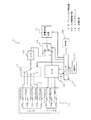
図1は、本発明によるオーディオ入力切替装置の実施の形態1の構成を示すブロック図である。
【0018】
同図のオーディオ入力切替装置1において、入力接続手段としての入力接続端子部10は、図示しない複数のオーディオソースとアナログ接続、またはディジタル接続する部分で、各オーディオソースのアナログ出力部と接続するための5つのアナログ入力端子10a〜10e、各オーディオソースのディジタル光出力部と光ケーブルで接続される2つの光入力端子10f,10g、及び、各オーディオソースのディジタル同軸出力部と同軸ケーブルで接続される1つ同軸入力端子10hが配設されている。
【0019】
尚、アナログ入力端子10a〜10eは、アナログ入力部に相当し、それぞれ左右の2チャンネル分の信号系を有するものであるが、簡単のため1チャンネルで示している。また、2つの光入力端子10f,10g、及び同軸入力端子10hは、ディジタル入力部に相当する。
【0020】
また、5つのアナログ入力端子10a〜10eには、それぞれ「アナログ入力1」〜「アナログ入力5」の名称を、2つの光入力端子10f,10gには、「ディジタル光入力1」、「ディジタル光入力2」の名称を、そして同軸入力端子10hには、「同軸入力」の名称をそれぞれ付し、以後、これらの各入力端子10a〜10hを名称で呼ぶことにする。
【0021】
アナログ信号選択手段に相当するアナログスイッチ11は、5つのアナログ入力1〜5から1つのアナログ入力を選択し、選択したアナログ入力に入力するアナログ入力信号をA/D変換器12に出力する。A/D変換器12は、入力したアナログ信号をディジタル信号に変換して信号選択手段に相当する切替スイッチ14の一方の信号入力部14aに出力する。
【0022】
ディジタル信号選択手段に相当するDIR(Digital Interface Receiver)13は、ディジタル光入力1、ディジタル光入力2及びディジタル同軸入力から1つの入力を選択し、選択したディジタル入力に入力するディジタル入力信号を選択して切替スイッチ14の他方の信号入力部14bに出力する。また、このDIR13は、ディジタル光入力1、ディジタル光入力2及びディジタル同軸入力に入力するディジタル信号の有無を検出し、そのディジタル信号入力情報INIを制御手段に相当するコントローラ16に出力する。
【0023】
切替スイッチ14は、各信号入力部14a,14bに入力するディジタル信号のうち一方を選択して音響処理回路15に出力する。音響処理回路15は、このディジタル信号を入力し、図示しないDSPなどで音響処理を施した後、各チャンネルの音声信号を出力する。各チャンネルの音声信号は、それぞれ図示しない増幅器等の所定の音声信号回路を経てスピーカに至る。
【0024】
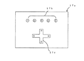
リモコン等による操作部17は操作手段に相当し、図2に示すような操作パネル17aを有し、オーディオソースを選択するためのソース指定部としての5つの選択ボタン17bと、後述するように、各種設定を行うための十字スイッチ17cが配設され、ユーザによって操作される際の操作信号OPEをコントローラ16に出力する。コントローラ16は、この操作信号OPEや、DIR13からのディジタル信号入力情報INIを入力し、これらの情報に基づいてアナログスイッチ11、DIR13、切替回路14、及び音響処理回路15の動作を制御すると共に、表示部18に後述する表示に必要な表示データを出力する。
【0025】
例えば、アナログスイッチ11を制御する場合、ユーザが操作パネル17a(図2)の選択ボタン17bを操作して所望のソース番号を選択した際の番号情報を操作部17から入力し、アナログスイッチ11の可動端子が同番号のアナログ入力を選択するようにアナログスイッチ11を制御する。
【0026】
以上の構成において、先ず信号の流れについて説明する。DVD,LD,TV,ビデオなどのオーディオソースの出力部は、入力接続端子部10の各入力端子に接続される。例えば、アナログ信号で接続する場合は、アナログ入力1〜アナログ入力5のいずれかに接続し、ディジタル信号を光ケーブルで接続する場合は、ディジタル光入力1又は2に接続し、ディジタル信号を同軸ケーブルで接続する場合は、ディジタル同軸入力に接続する。
【0027】
いま、複数のオーディオソースがあって、各オーディオソースのアナログ出力部が、入力接続端子部10の各アナログ入力1〜アナログ入力5の何れかに接続された場合、アナログ入力1に接続されたオーディオソースをオーディオソース1と称し、以下同様にして各アナログ入力2〜5に接続されたオーディオソースをそれぞれオーディオソース2〜5と称す。
【0028】
一方、コントローラ16は、ディジタル信号を入力する3つの入力端子、即ちディジタル光入力1,2及びディジタル同軸入力と、操作パネル17a(図2)に配設されたオーディオソースを選択するための5つの選択ボタン17bとの対応関係を予め設定したテーブルを内蔵し、これに基づいてDIR13の選択動作を制御する。
【0029】
図3は、このテーブルに設定された対応関係の一例を示す表であるが、この場合、操作者によってオーディオソース1の選択ボタンが選択されると、DIR13がディジタル光入力1に入力するディジタル信号を選択して切替スイッチ14の他方の信号入力部14bに出力するように制御し、オーディオソース4の選択ボタンが選択されると、DIR13がディジタル同軸入力に入力するディジタル信号を選択して切替スイッチ14の他方の信号入力部14bに出力するように制御する。またこの場合、光入力2は未接続とされているため、例え、この端子に信号が入力されても、これが選択されて切替スイッチ14に出力されることはない。
【0030】
以上の設定は、ユーザによって行われる。例えばコントローラ16は、この設定モード時に、図3の表を表示部18に表示し、ユーザはこの表を見ながら十字スイッチ17cを操作して入力欄を選択し、所望の入力欄に○印を入力して各オーディオソースとディジタル信号入力との対応関係を設定する。さらにユーザは、この表の対応関係に従って、図示しないオーディオソース1の光出力端子と入力接続端子部10のディジタル光入力1を光ケーブルで接続し、図示しないオーディオソース4の同軸力端子と入力接続端子部10のディジタル同軸入力を同軸ケーブルで接続する。
【0031】
以上の接続及び設定状態において、アナログ入力1〜5にそれぞれ入力する各アナログ信号は、ユーザの選択操作に基づくコントローラ16の指令によってアナログスイッチ11で選択され、A/D変換器12によってディジタル信号に変換された後、切替スイッチ14の一方の信号入力部14aに入力する。例えばユーザが、前記したように操作部17を操作してオーディオソース1を選択した場合、コントローラ16は、アナログスイッチ11がアナログ入力1に入力するアナログ信号を選択して切替スイッチ14に出力するように制御する。
【0032】
一方、ディジタル光入力1、ディジタル光入力2、及びディジタル同軸入力に入力する各ディジタル信号は、前記したようにテーブル(図3)の対応関係に従って、コントローラ16の指令によってDIR13で選択され、切替スイッチ14の他方の信号入力部14bに入力する。例えばユーザが、操作部17を操作してオーディオソース1を選択した場合、コントローラ16は、DIR13が、テーブル(図3)の対応関係に従ってディジタル光入力1に入力するディジタル信号を選択して切替スイッチ14に出力するように制御する。
【0033】
また、ディジタル光入力1、ディジタル光入力2、及びディジタル同軸入力の各ディジタル入力部は、DIR13によって、実際にディジタル信号を入力しているか否かが検出され、その検出結果を含むディジタル信号入力情報INIがDIR13からコントローラ16に出力される。
【0034】
切替スイッチ15は、コントローラ16の指令に基づいて、信号入力部14aに入力するアナログ系統、又は信号入力部14bに入力するディジタル系統の信号を選択して音響処理回路15に出力する。例えば、ユーザがオーディオソース1を選択した場合、切替スイッチ14の各信号入力部14a及び14bにはそれぞれアナログ系統(A/D変換されている)及びディジタル系統の信号が入力する状態となるが、このとき切替スイッチ14は、後述する優先順位に従って信号入力部14bに入力するディジタル光入力1のディジタル信号を選択して音響処理回路15に出力する。
【0035】
また、ユーザがオーディオソース2、3、5の何れかを選択した場合、図3の表に示すように対応するディジタル入力がないため、DIR13からは信号が出力されず、切替スイッチ15は、後述するフローに従って入力部14aに入るアナログ系統(A/D変換されている)のディジタル信号を選択する。
【0036】
音響処理回路15は、切替スイッチ15で選択したディジタル信号を入力し、コントローラ16の指令によって最適な音場を作り出すための演算を行い、フロントL、フロントR、リアL、リアRなどのチャンネル別にD/A変換したアナログオーディオ信号を図示しない各増幅器にそれぞれ出力する。
【0037】
次に、コントローラ16が、操作部17から入力する操作信号OPEやDIR13から入力するディジタル信号入力情報INIを入力し、オーディオ入力切替装置1全体を制御する手順について、図4のフローチャートを参照しながら説明する。
【0038】
ユーザが、操作パネル17aに配設された選択ボタン17bを操作するのを監視し(ステップ1)、所望のオーディオソース番号n(1〜5の整数)が選択されると、内臓するテーブル(図3)をチェックし、選択されたオーディオソース番号nに対応設定されたディジタル入力(ディジタル光入力1,2及びディジタル同軸入力)が有るか否か、更には該当するディジタル入力にディジタル信号が入力されているか否かをチェックする(ステップ2〜ステップ4)。そして、該当するディジタル入力が有る場合、そこに入力されているディジタル信号を選択し、前記した所定の経路を介して形成したアナログオーディオ信号を出力する(ステップ5〜ステップ7)。
【0039】
もし選択されたオーディオソース番号nに対してディジタル入力が対応設定されていなかったり、対応設定されている場合でも、ディジタル信号が入力されてなかった場合、アナログ入力(n)に接続されたオーディオソース(n)のアナログ信号が選択され、前記した所定の経路を介して形成したアナログオーディオ信号を出力する(ステップ8)。
【0040】
その後、ディジタル入力のテーブルへの登録もれが無いかをチェックする。即ち、ディジタル信号が入っているにもかかわらず、テーブルへ登録されていないディジタル入力を検出する(ステップ9〜ステップ11)。この状態は、例えばユーザが、所望のオーディオソース(n)のディジタル出力と、あるディジタル入力とをケーブルで接続したにもかかわらず、このディジタル入力が選択されない状態に相当する。
【0041】
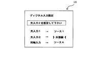
もし、このような登録もれのディジタル入力が存在した場合、例えば図3の表に示すようにディジタル光入力2が未接続で、更にこのディジタル光入力2がディジタルソース(5)の光出力部と光ケーブルで接続されている場合、ステップ11でこの状態が検出され、ステップ14に移ってこの光入力2の設定作業を行う。例えば、このときコントローラ16は、その表示部18に、図5に示す画像を表示させる。ユーザは、この画面をみて、各ディジタル入力の設定状態を確認し、操作パネル17aの十字スイッチ17c(図3)で光入力2の「未接続」を選択し、選択ボタン17bでソース5を入力設定する。
【0042】
この入力設定が完了すると再びステップ1に移ってユーザによるソース選択を監視する状態となり、以後同様の動作を繰り返す。
【0043】
以上のように、実施の形態1のオーディオ入力切替装置1によれば、限られた数のディジタル入力をアナログ入力に対して任意に対応させ、入力するアナログとディジタルの各オーディオ信号を処理するため、ディジタル入力の数を無闇に増やすことなく、無駄のない理想的な信号切替が可能となる。
【0044】
また、1つのオーディオソースからアナログとディジタルによる同内容のオーディオ信号を入力する場合、自動的に音質の優れたディジタル入力信号を優先的に選択するため、ユーザによる選択操作数を減らすことができ、操作の煩雑を避けることができる。
【0045】
また、所望のオーディオソースに接続したディジタル入力を、そのオーディオソースのアナログ信号を入力するアナログ入力に対応させる設定を忘れた場合にも、このミスを検出して接続を促すように構成されているため、ユーザの設定忘れミスを防ぐことができる。
【0046】
尚、前記した実施の形態では、未設定のディジタル入力の設定画面として図5のレイアウトを示したが、これに限定されるものではなく、例えば図3の表を表示させ、選択可能欄(実施例の場合、光入力2のオーディオソース番号2,3,5の欄が相当する)を色を換えて表示してもよいなど、種々の態様を取り得るものである。
【0047】
【発明の効果】
請求項1,2,及び7のオーディオ入力切替装置によれば、限られた数のディジタル入力をアナログ入力に対して対応させ、入力するアナログとディジタルの各オーディオ信号を処理することが可能となるため、ディジタル入力の数を無闇に増やすことなく、ディジタル入力を無駄なく効果的に利用することができる。
【0048】
請求項3,4のオーディオ入力切替装置によれば、1つのオーディオソースからアナログとディジタルによる同内容のオーディオ信号を入力する場合、自動的に音質の優れたディジタル入力信号を優先的に選択するため、ユーザによる選択操作数を減らすことができ、操作の煩雑を避けることができる。また、ディジタル入力に信号が入力されていない状態では、これを検出し、アナログ入力信号を選択することができるため、オーディオソースが再生ソフトによってアナログ信号のみを出力する場合があっても対応できる。
【0049】
請求項3,5のオーディオ入力切替装置によれば、所望のオーディオソースに接続したディジタル入力を、そのオーディオソースのアナログ信号を入力するアナログ入力に対応させる設定を忘れた場合にも、このミスを検出して接続を促すことが可能なため、ユーザの設定忘れミスを防ぐことができる。
【0050】
請求項6のオーディオ入力切替装置によれば、請求項1の効果に加え、ディジタル入力とアナログ入力の対応を自由に設定できるため、オーディオソースとの接続において、その自由度を増すことができる。
【図面の簡単な説明】
【図1】本発明によるオーディオ入力切替装置の実施の形態1の構成を示すブロック図である。
【図2】操作部17の操作部パネル17aのレイアウトを示す構成図である。
【図3】コントローラ16のテーブルに設定された対応関係の一例を示す表を示す図である。
【図4】コントローラ16が、オーディオ入力切替装置1全体を制御する手順を示すフローチャートである。
【図5】ディジタル入力の設定作業を行う際に表示部18に表示される画像を示す図である。
【符号の説明】
1 オーディオ入力切替装置、 10 入力接続端子部、 10a〜10e アナログ入力端子、 10f,10g 光入力端子、 10h 同軸入力端子、11 アナログスイッチ、 12 A/D変換器、 13 DIR、 14 切替スイッチ、 14a,14b 信号入力部、 15 音響処理回路、 16コントローラ、 17 操作部、 17a 操作パネル、 17b 選択ボタン、 17c 十字スイッチ、 18 表示部。[0001]
TECHNICAL FIELD OF THE INVENTION
The present invention relates to an audio input switching device and an audio input switching method for inputting analog signals and digital signals output from a plurality of audio sources such as DVD and LD, and selecting and reproducing an audio signal of a desired audio source. About.
[0002]
[Prior art]
A large number of various audio sources such as an analog cassette deck, a CD player, an MD player, a satellite television broadcast receiving tuner, and an LD player can be generally connected to an AV amplifier, an audio amplifier, and the like. When a user selects a desired audio source, a signal input from the audio source is selected.
The selected input signal is converted into a predetermined digital audio signal format that can be processed by an audio processing circuit including a DSP (Digital Signal Processor) for controlling a sound field, for example, and is input to the audio processing circuit. Has become. In the sound processing circuit, the digital audio signal is subjected to sound field processing by the DSP, and then D / A converted for each channel such as front L, front R, rear L, rear R, and output.
[0004]
CD players, MD players, satellite television broadcast receiving tuners, and LD players output audio signals not only in an analog format but also in a digital format using a coaxial cable with less disturbance. Output is also possible.
[0005]
In response to such diversification of output methods of audio source devices, AV amplifiers and the like can not only connect a plurality of audio source devices at the same time, but also provide analog input and coaxial input to some digital audio source devices. , A plurality of input systems can be simultaneously connected among the optical inputs. For this reason, the user operates the AV amplifier with a remote controller or the like, selects a source device from among a plurality of audio source devices, and selects the above-described input system, thereby listening to a desired audio source with the best sound quality. be able to.
[0006]
On the other hand, according to Japanese Patent Application Laid-Open No. Hei 9-128886 as another conventional example, detection means for detecting a system of a system having an input (a signal has arrived) among audio sources desired by a user as a selection means. Means and, among the systems detected by the detection means, a determination means for determining the highest priority when viewed in a preset priority order, for example, optical input, coaxial input, analog input priority. And selecting the input determined by the determination means from the inputs of the plurality of input systems and outputting the signal in a predetermined signal format, thereby eliminating the input system selection operation after the source selection operation. For this purpose, a technique has been disclosed.
[0007]
Further, according to still another conventional example, as a method for omitting the input system selection operation after the source selection operation, a method of setting the input system for each audio source in advance has been considered. .
[Problems to be solved by the invention]
In the audio input switching device according to the first conventional example described above, each time the user selects an audio source, it is necessary to further select one input system from among the optical input, coaxial input, and analog input. The selection operation may be complicated.
[0008]
Further, in the above-described another conventional example, it is necessary to prepare an input system that can be selected for each audio source, so that the number of input terminals and paths related thereto is increased, and the cost as a product is reduced. There was a problem of getting high.
[0009]
Furthermore, in the above-mentioned another conventional example, if the user neglected the initial setting, no sound was produced, or the initial setting had to be reset every time the connection with each audio source was changed, which involved complicated aspects. .
[0010]
An object of the present invention is to solve the above problems, reduce the cost of the product, make it possible for the user to set the input system reliably and easily, and after setting, automatically switch the audio source to automatically obtain the optimal input. It is to provide an audio input switching device and an audio input switching method for selecting a system.
[0011]
[Means for Solving the Problems]
The audio input switching device of
A plurality of analog inputs, each connectable to an analog output of the audio source, and one or more digital inputs, fewer in number than the analog inputs, each connectable to a digital output of the audio source. An input connection unit, at least an operation unit having a source designation unit capable of designating one of the plurality of analog input units, and one of an analog signal input to the analog input unit Analog signal selecting means capable of selecting and outputting, digital signal selecting means capable of selecting and outputting one of digital signals input to the digital input section, the digital input section and the analog signal A table for storing data individually associated with the input unit, and inputting the data to the analog input unit designated by the source designation unit; Controlling the analog signal selecting means so as to select an analog signal to be inputted, and when the digital input section corresponding to the analog input section designated by the source designation section is set, the digital signal inputted to the digital input section is inputted. Control means for controlling the digital signal selection means so as to select a signal.
[0012]
The audio input switching device according to
Further, one of an analog input system digital signal obtained by A / D conversion of an analog signal output from the analog signal selection unit and a digital input system digital signal output from the digital signal selection unit is selected and output. It is characterized by having signal selection means.
[0013]
The audio input switching device according to
The digital signal selecting means detects whether or not a digital signal is input to each of the digital input sections, and outputs digital signal input information including the detected information to the control means.
[0014]
The audio input switching device according to
When the control means outputs the analog signal and the digital signal input to the corresponding analog input unit and the digital input unit, respectively, the analog signal selection means and the digital signal selection means The signal selection means is controlled so that a digital signal of a digital input system is preferentially selected.
[0015]
The audio input switching device according to claim 5 is the audio input switching device according to
The control means has a display unit, and if the corresponding analog input unit is not set in the table with respect to the digital input unit where it is detected that the digital signal is being input, the state is displayed on the display. It is displayed on a section.
The audio input switching device according to claim 6 is the audio input switching device according to
The control means has a display unit for displaying the storage contents of the table, and the storage contents of the table can be changed by operating the operation means.
[0016]
The audio input switching method according to
An analog signal to be input to a plurality of analog inputs each of which can be connected to an analog output of the audio source; An audio input switching method for selecting any one of a digital signal input to an input unit,
A step of designating one of the plurality of analog input sections, a step of selecting an analog signal to be input to the analog input section designated in the step, and separately setting the digital input section and the analog input section. Selecting the digital signal to be input to the digital input unit when the digital input unit corresponding to the specified analog input unit is set based on a table storing the associated data. It is characterized by.
[0017]
BEST MODE FOR CARRYING OUT THE INVENTION
FIG. 1 is a block diagram showing a configuration of an audio input switching device according to a first embodiment of the present invention.
[0018]
In the audio
[0019]
Note that the
[0020]
The names of “
[0021]
The analog switch 11 corresponding to the analog signal selection means selects one analog input from five
[0022]
A DIR (Digital Interface Receiver) 13 corresponding to digital signal selection means selects one input from digital
[0023]
The
[0024]
An
[0025]
For example, when controlling the analog switch 11, the user operates the selection button 17 b of the operation panel 17 a (FIG. 2) to input the number information when the desired source number is selected from the
[0026]
In the above configuration, the signal flow will be described first. An output unit of an audio source such as a DVD, LD, TV, or video is connected to each input terminal of the input
[0027]
Now, when there are a plurality of audio sources, and the analog output section of each audio source is connected to any one of the
[0028]
On the other hand, the
[0029]
FIG. 3 is a table showing an example of the correspondence set in this table. In this case, when the operator selects the
[0030]
The above settings are made by the user. For example, the
[0031]
In the above connection and setting state, each analog signal input to each of the
[0032]
On the other hand, each digital signal input to the digital
[0033]
The
[0034]
The
[0035]
When the user selects one of the
[0036]
The
[0037]
Next, a procedure in which the
[0038]
It is monitored that the user operates the selection button 17b arranged on the operation panel 17a (step 1), and when a desired audio source number n (integer of 1 to 5) is selected, a built-in table (FIG. Check 3) to see if there is a digital input (digital
[0039]
If the digital input is not set corresponding to the selected audio source number n, or if the digital signal is not input even if the corresponding input is set, the audio source connected to the analog input (n) The analog signal of (n) is selected, and the analog audio signal formed via the predetermined path is output (step 8).
[0040]
After that, it is checked whether there is any omission of registration of the digital input in the table. That is, a digital input that is not registered in the table is detected even though a digital signal is input (steps 9 to 11). This state corresponds to, for example, a state where the digital input of the desired audio source (n) is connected to a certain digital input with a cable, but the digital input is not selected.
[0041]
If such a missing digital input exists, for example, as shown in the table of FIG. 3, the digital
[0042]
When the input setting is completed, the process returns to step 1 to monitor the source selection by the user, and thereafter, the same operation is repeated.
[0043]
As described above, according to the audio
[0044]
In addition, when inputting the same analog and digital audio signals from one audio source, the digital input signal having excellent sound quality is automatically preferentially selected, so that the number of selection operations by the user can be reduced, Operational complexity can be avoided.
[0045]
Further, even if the user forgets to set the digital input connected to the desired audio source to correspond to the analog input for inputting the analog signal of the audio source, this mistake is detected to prompt connection. For this reason, it is possible to prevent the user from forgetting to set the settings.
[0046]
In the above-described embodiment, the layout of FIG. 5 is shown as a setting screen of a digital input that has not been set. However, the present invention is not limited to this. For example, a table of FIG. In the case of the example, the fields of the
[0047]
【The invention's effect】
According to the audio input switching device of the first, second, and seventh aspects, it is possible to make a limited number of digital inputs correspond to the analog inputs and process the input analog and digital audio signals. Therefore, the digital inputs can be effectively used without waste without unnecessarily increasing the number of digital inputs.
[0048]
According to the audio input switching device of the third and fourth aspects, when an analog and digital audio signal of the same content is input from one audio source, a digital input signal having excellent sound quality is automatically selected with priority. In addition, the number of selection operations by the user can be reduced, and the complexity of the operation can be avoided. Further, when no signal is input to the digital input, this can be detected and an analog input signal can be selected, so that it is possible to cope with a case where the audio source outputs only an analog signal by reproduction software.
[0049]
According to the audio input switching device of the third and fifth aspects, even if the user forgets to set the digital input connected to the desired audio source to correspond to the analog input for inputting the analog signal of the audio source, this mistake can be eliminated. Since it is possible to detect and prompt the connection, it is possible to prevent the user from mistakenly forgetting the setting.
[0050]
According to the audio input switching device of the sixth aspect, in addition to the effect of the first aspect, the correspondence between the digital input and the analog input can be freely set, so that the degree of freedom in connection with the audio source can be increased.
[Brief description of the drawings]
FIG. 1 is a block diagram showing a configuration of an audio input switching device according to a first embodiment of the present invention.
FIG. 2 is a configuration diagram illustrating a layout of an operation unit panel 17a of the
FIG. 3 is a table showing an example of a correspondence set in a table of a
FIG. 4 is a flowchart showing a procedure in which the
FIG. 5 is a diagram showing an image displayed on a
[Explanation of symbols]
Claims (7)
少なくとも、前記複数のアナログ入力部のうちの1つを指定可能なソース指定部を有する操作手段と、
前記アナログ入力部に入力されるアナログ信号のうち1つを択一的に選択して出力可能なアナログ信号選択手段と、
前記ディジタル入力部に入力されるディジタル信号のうち1つを択一的に選択して出力可能なディジタル信号選択手段と、
前記ディジタル入力部と前記アナログ入力部とを個別に対応させたデータを記憶するテーブルを有し、前記ソース指定部で指定した前記アナログ入力部に入力するアナログ信号を選択するよう前記アナログ信号選択手段を制御すると共に、前記ソース指定部で指定した前記アナログ入力部に対応する前記ディジタル入力部が設定されている場合、該ディジタル入力部に入力するディジタル信号を選択するよう前記ディジタル信号選択手段を制御する制御手段と
を有することを特徴とするオーディオ入力切替装置。A plurality of analog inputs, each connectable to an analog output of the audio source, and one or more digital inputs, fewer in number than the analog inputs, each connectable to a digital output of the audio source. Input connection means;
At least operating means having a source designation unit capable of designating one of the plurality of analog input units;
Analog signal selecting means capable of selectively selecting one of the analog signals input to the analog input unit and outputting the selected signal;
Digital signal selection means for selectively selecting and outputting one of digital signals input to the digital input unit;
The analog signal selecting means having a table for storing data in which the digital input unit and the analog input unit are individually associated, and selecting an analog signal to be input to the analog input unit specified by the source specifying unit. And when the digital input section corresponding to the analog input section specified by the source specifying section is set, controls the digital signal selection means to select a digital signal to be input to the digital input section. An audio input switching device, comprising:
前記複数のアナログ入力部のうちの1つを指定するステップと、
該ステップで指定されたアナログ入力部に入力するアナログ信号を選択するステップと、
前記ディジタル入力部と前記アナログ入力部とを個別に対応させたデータを記憶するテーブルに基づいて、前記指定されたアナログ入力部に対応する前記ディジタル入力部が設定されている場合、該ディジタル入力部に入力するディジタル信号を選択するステップと
を有することを特徴とするオーディオ入力切替方法。An analog signal to be input to a plurality of analog inputs each of which can be connected to an analog output of the audio source; and one or more digital signals each having a smaller number than the analog inputs and each of which can be connected to the digital output of the audio source. An audio input switching method for selecting any one of a digital signal input to an input unit,
Designating one of the plurality of analog inputs;
Selecting an analog signal to be input to the analog input unit specified in the step;
When the digital input unit corresponding to the designated analog input unit is set based on a table storing data in which the digital input unit and the analog input unit are individually associated, the digital input unit Selecting a digital signal to be input to the audio input device.
Priority Applications (1)
| Application Number | Priority Date | Filing Date | Title |
|---|---|---|---|
| JP2002194127A JP2004039085A (en) | 2002-07-03 | 2002-07-03 | Device and method for switching audio inputs |
Applications Claiming Priority (1)
| Application Number | Priority Date | Filing Date | Title |
|---|---|---|---|
| JP2002194127A JP2004039085A (en) | 2002-07-03 | 2002-07-03 | Device and method for switching audio inputs |
Publications (2)
| Publication Number | Publication Date |
|---|---|
| JP2004039085A true JP2004039085A (en) | 2004-02-05 |
| JP2004039085A5 JP2004039085A5 (en) | 2005-08-04 |
Family
ID=31702896
Family Applications (1)
| Application Number | Title | Priority Date | Filing Date |
|---|---|---|---|
| JP2002194127A Pending JP2004039085A (en) | 2002-07-03 | 2002-07-03 | Device and method for switching audio inputs |
Country Status (1)
| Country | Link |
|---|---|
| JP (1) | JP2004039085A (en) |
Cited By (4)
| Publication number | Priority date | Publication date | Assignee | Title |
|---|---|---|---|---|
| JP2009044257A (en) * | 2007-08-06 | 2009-02-26 | Yamaha Corp | Audio signal output apparatus |
| JP2011244353A (en) * | 2010-05-20 | 2011-12-01 | Onkyo Corp | Selector device |
| US9424849B2 (en) | 2011-12-14 | 2016-08-23 | Cirrus Logic, Inc. | Data transfer |
| US11675565B2 (en) | 2021-09-07 | 2023-06-13 | ACCO Brands Corporation | Audio switching device |
-
2002
- 2002-07-03 JP JP2002194127A patent/JP2004039085A/en active Pending
Cited By (5)
| Publication number | Priority date | Publication date | Assignee | Title |
|---|---|---|---|---|
| JP2009044257A (en) * | 2007-08-06 | 2009-02-26 | Yamaha Corp | Audio signal output apparatus |
| US8565451B2 (en) | 2007-08-06 | 2013-10-22 | Yamaha Corporation | Audio signal output device |
| JP2011244353A (en) * | 2010-05-20 | 2011-12-01 | Onkyo Corp | Selector device |
| US9424849B2 (en) | 2011-12-14 | 2016-08-23 | Cirrus Logic, Inc. | Data transfer |
| US11675565B2 (en) | 2021-09-07 | 2023-06-13 | ACCO Brands Corporation | Audio switching device |
Similar Documents
| Publication | Publication Date | Title |
|---|---|---|
| US7970155B2 (en) | Video/audio output device and external speaker control apparatus | |
| TWI264962B (en) | Sound device and its configuration method | |
| KR0183682B1 (en) | A karaoke tv | |
| US20050154766A1 (en) | Multimedia processing system capable of auto-detecting multimedia signals to facilitate selecting and method of the same | |
| US5646699A (en) | CDP-incorporated television receiver which selects a signal based on a type of compact disk detected | |
| US7212253B1 (en) | Home entertainment system audio handling | |
| JP2008177974A (en) | Display device | |
| JP5125134B2 (en) | AV equipment | |
| JP2004039085A (en) | Device and method for switching audio inputs | |
| JPH0898102A (en) | Television receiver | |
| JP4747830B2 (en) | Audio apparatus and output switching method | |
| JP2010278579A (en) | Apparatus for selection of source equipment | |
| JPH0636529Y2 (en) | AV system | |
| JP2006050195A (en) | Av amplifier | |
| CN100508576C (en) | Image-sound playing system capable of automatically detecting/selecting image-sound signals and method thereof | |
| JP2006222765A (en) | Sound-reproducing system | |
| JP3606424B2 (en) | AV system | |
| US20030194202A1 (en) | Combination system and operation control method for controlling each of a plurality of devices through a single on-screen display | |
| JP4040305B2 (en) | Monitor device | |
| KR100260496B1 (en) | Control method and control apparatus of combination image systems | |
| JP2805625B2 (en) | Audio signal processing device | |
| JPH09307833A (en) | Audio controller for video equipment and audio control method | |
| JPH1118016A (en) | Video equipment having audio signal input terminal | |
| KR20070073284A (en) | Display apparatus | |
| JP2001333500A (en) | Av equipment and audio input method for the av equipment |
Legal Events
| Date | Code | Title | Description |
|---|---|---|---|
| A521 | Written amendment |
Free format text: JAPANESE INTERMEDIATE CODE: A523 Effective date: 20041227 |
|
| A621 | Written request for application examination |
Free format text: JAPANESE INTERMEDIATE CODE: A621 Effective date: 20041227 |
|
| A977 | Report on retrieval |
Free format text: JAPANESE INTERMEDIATE CODE: A971007 Effective date: 20060828 |
|
| A131 | Notification of reasons for refusal |
Free format text: JAPANESE INTERMEDIATE CODE: A131 Effective date: 20060905 |
|
| A02 | Decision of refusal |
Free format text: JAPANESE INTERMEDIATE CODE: A02 Effective date: 20061226 |