JP2004021916A - Data bus - Google Patents
Data bus Download PDFInfo
- Publication number
- JP2004021916A JP2004021916A JP2002179969A JP2002179969A JP2004021916A JP 2004021916 A JP2004021916 A JP 2004021916A JP 2002179969 A JP2002179969 A JP 2002179969A JP 2002179969 A JP2002179969 A JP 2002179969A JP 2004021916 A JP2004021916 A JP 2004021916A
- Authority
- JP
- Japan
- Prior art keywords
- data
- impedance
- terminating
- signal
- variable resistor
- Prior art date
- Legal status (The legal status is an assumption and is not a legal conclusion. Google has not performed a legal analysis and makes no representation as to the accuracy of the status listed.)
- Pending
Links
Images


Classifications
-
- G—PHYSICS
- G11—INFORMATION STORAGE
- G11C—STATIC STORES
- G11C7/00—Arrangements for writing information into, or reading information out from, a digital store
- G11C7/10—Input/output [I/O] data interface arrangements, e.g. I/O data control circuits, I/O data buffers
Landscapes
- Dram (AREA)
- Memory System (AREA)
- Logic Circuits (AREA)
Abstract
Description
【0001】
【発明の属する技術分野】
本発明はデータバスを用いてデータの授受を行う技術に関するものである。
【0002】
【従来の技術】
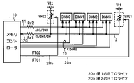
図15および図16は、コンピュータシステムのマザーボード上に構築される従来のメモリシステムの構成を示す図である。ここでは、メモリシステムの一例として、DRAM(Dynamic Random Access Memory)を搭載したDIMM(Dual Inline Memory Module)を4個搭載するメモリシステムを示している。同図に示すように、メモリコントローラ10と4個のDIMM(DIMM0〜DIMM3)との間は、アドレス/コマンドバス11、データバス12、クロックライン13により接続されている。
【0003】
メモリコントローラ10はアドレス/コマンドバス11およびデータバス12を介して、4個のDIMMのそれぞれの動作を制御すると共に、各DIMMに対してデータの書き込み及び読み出しを行う。アドレス/コマンドバス11は、メモリコントローラ10が出力する命令信号(CMD)およびアドレス信号(ADD)を各DIMMに転送するためのバスである。命令信号(CMD)とは、メモリコントローラ10がそれぞれのDIMMに対してデータの書き込みあるいは読み出しの指示を行うための信号である。また、アドレス信号(ADD)とは、その書き込みあるいは読み出しの対象となるDRAMのアドレスを指定するための信号である。
【0004】
データバス12は、メモリコントローラ10と各DIMM間のデータの転送を担うバスであり、メモリコントローラ10と各DIMM間での双方向のデータ転送が可能である。即ち、メモリコントローラ10がDIMMに対してデータの書き込みを行う場合、データバス12はメモリコントローラ10が出力するデータ(書き込みデータ)をDIMMへと転送し、反対にメモリコントローラ10がDIMMに対してデータの読み出しを行う場合、DIMMから出力されたデータ(読み出しデータ)をメモリコントローラ10へと転送する。
【0005】
また、データバス12を介してメモリコントローラ10とDIMMとの間でやりとりされる信号としては、書き込み及び読み出しの対象そのものであるデータ信号(DQ)の他、メモリコントローラ10あるいはDIMM内のDRAMがデータを取り込む際に用いられるデータストローブ(Data Strobe)信号(DQS)や、データをマスクするための信号(DM)等がある。なお、説明の簡単のために図示は省略したが、アドレス/コマンドバス11やデータバス12等のメモリバスはそれぞれ複数の信号線によって構成されている。例えば、DQ/DQS/DMの転送を担うデータバス12であれば、108本程度の信号線により構成されるのが一般的である。
【0006】
また、メモリコントローラ1は、メモリシステムの動作タイミングの基準となる基準周波数を有する基準クロック信号を、クロックライン13を介してそれぞれのDIMMに送信する。
【0007】
ここで、図15に示した従来のメモリシステムの動作を簡単に説明する。例えば、DIMMへのデータの書き込みを行う場合、まず、メモリコントローラ10はアドレス/コマンドバス11を介して、DIMMに対しデータの書き込み指示を行う命令信号(CMD)を出力すると共にアドレス信号(ADD)によりその書き込みの対象となるアドレスを指定する。その後、メモリコントローラ10がデータバス12を介して書き込みデータをDIMMへ転送することで、指定されたアドレスに当該データが書き込まれる。
【0008】
反対に、DIMMからのデータの読み出しを行う場合、まず、メモリコントローラ10はアドレス/コマンドバス11を介して、DIMMに対しデータの読み出し指示を行う命令信号(CMD)を出力する共にアドレス信号(ADD)によりその読み出しの対象となるアドレスを指定する。すると、DIMMの指定されたアドレスに記憶されたデータが読み出される。そのデータ(読み出しデータ)はデータバス12を介してメモリコントローラ10へと転送され、メモリコントローラ10によって当該読み出しデータが読み込まれる。
【0009】
ところで、アドレス/コマンドバス11やデータバス12等のメモリバスにおいてデータ信号の転送の際に反射が生じると、その影響により信号歪みが発生する。従って、反射の発生を抑える目的でメモリバスの信号線路におけるインピーダンス整合をとることは重要である。よって一般に、メモリバスを構成するそれぞれの信号線は所定の終端抵抗により終端される。
【0010】
例えば図15では、データバス12には、その信号線に対して直列接続された直列抵抗Rs1と、終端抵抗Rt1が備え付けられている。また、アドレス/コマンドバス11には、その信号線に対して直列接続された直列抵抗Rs2が備え付けられている。また、終端抵抗Rtは所定の電圧Vttに接続されるが、通常Vttは電源電圧の半分程度の電圧に設定される。なお、上記したようにメモリバスを構成する個々の信号線の図示は省略しているが、終端抵抗はメモリバスを構成する信号線のそれぞれが有している。
【0011】
一般的に終端抵抗は、転送される信号の受信側に近い位置に接続させる方が、受信側における信号歪みをより効果的に抑えることができる。上記したようにデータバス12は双方向の信号の転送を担っているので、DIMMからのデータ読み出しの際のデータ転送を考慮し、データバス12の信号線の終端抵抗を図16のような構成としても良い。つまり、データバス12を構成する信号線のうちメモリコントローラ1が接続された第1端側においてDIMMよりもメモリコントローラ10に近い方に(即ち、メモリコントローラ10とDIMMとの間)にも終端抵抗Rt2を備え付けてもよい。それにより、DIMMからの読み出し動作の際に、メモリコントローラ10で受信される信号の歪みを図15の例よりも効果的に抑えることができる。
【0012】
近年、メモリシステムの動作の高速化および低消費電力化を図るために、メモリコントローラ10とのDIMM間における信号の振幅は小さく抑えられる傾向にある。それに伴い、信号の振幅のマージンは減少してきており、信号歪みを抑えることの重要性はさらに高まっている。従って、メモリバスを構成する信号線に直列抵抗や終端抵抗を備え付けることでインピーダンス整合を図り、反射の影響による信号歪みを抑えることの重要性はさらに高まっている。
【0013】
【発明が解決しようとする課題】
上記の例で示したデータバス12のように、信号線が双方向のデータの転送を担う場合、特に転送する信号の周波数が高くなると、信号の一の方向への転送の際のインピーダンス整合と他の方向への転送の際のインピーダンス整合の両方をバランスよく保つことは困難になる。つまり、データバス12の終端抵抗Rt1、Rt2並びに直列抵抗Rs1が信号歪みを抑える効果が、データの転送方向により異なる場合がある。その場合、DIMMへのデータ書き込み時(メモリコントローラ10からDIMMへのデータ転送時)と、DIMMからのデータ読み出し時(DIMMからメモリコントローラ10へのデータ転送時)とで、直列抵抗や終端抵抗が信号歪みを抑える効果に違いが生じる。
【0014】
従って、例えばDIMMへのデータ書き込み時における信号歪みを抑えるようにインピーダンスを設定された終端抵抗を使用すると、逆に、読み出し時におけるインピーダンス整合が崩れ、読み出し時におけるデータ信号の波形に歪みが生じる。その結果、データバス12で転送される信号の振幅にある程度のマージンを持たせる必要が生じ、メモリシステムの動作の高速化および低消費電力化の妨げとなる。
【0015】
本発明は以上のような課題を解決するためになされたものであり、双方向へのデータ転送を担うデータバスを有するメモリシステムにおいて、データ転送の方向を問わず信頼性の高いデータの転送が可能なデータバスを提供することを目的とする。
【0016】
【課題を解決するための手段】
請求項1に記載のデータバスは、双方向にデータを転送可能な信号線と、前記信号線を終端する少なくとも一つの終端素子とを備え、前記少なくとも一つの終端素子のインピーダンスは、前記データが転送される方向に応じて可変である。
【0017】
請求項2に記載のデータバスは、請求項1記載のデータバスにおいて、前記信号線に対して直列に接続された可変インピーダンス素子を更に備え、前記可変インピーダンス素子のインピーダンスは、前記データが転送される方向に応じて可変である。
【0018】
請求項3に記載のデータバスは、双方向にデータを転送可能な信号線と、前記信号線に対して直列に接続された可変インピーダンス素子とを備え、前記可変インピーダンス素子のインピーダンスは、前記データが転送される方向に応じて可変である。
【0019】
請求項4に記載のデータバスは、請求項1及び請求項3のいずれか一つに記載のデータバスにおいて、第1端及び第2端と、前記第1端と前記第2端との間から分岐する少なくとも一つの第3端とを有し、前記少なくとも一つの第3端の各々には前記データの読み出し/書き込みが可能なメモリが接続され、前記少なくとも一つの終端素子は、前記第2端に接続されて前記読み出し/書き込み動作に応じて異なる抵抗値を採る第1の終端可変抵抗を有する。
【0020】
請求項5に記載のデータバスは、請求項4記載のデータバスにおいて、前記第1端には、前記メモリに対する書き込みデータの送信と、前記メモリからの読み出しデータの受信とを行うメモリコントローラが接続され、前記書き込みの際には前記読み出しの際よりも、前記第1の終端可変抵抗の抵抗値が小さい。
【0021】
請求項6に記載のデータバスは、請求項4及び請求項5のいずれか一つに記載のデータバスにおいて、前記少なくとも一つの終端素子は、前記第1端に接続されて前記読み出し/書き込み動作に応じて異なる抵抗値を採る第2の終端可変抵抗を更に有する。
【0022】
請求項7に記載のデータバスは、請求項6記載のデータバスにおいて、前記第1端には、前記メモリに対する書き込みデータの送信と、前記メモリからの読み出しデータの受信とを行うメモリコントローラが接続され、前記書き込みの際には前記第2の終端可変抵抗の抵抗値を無限大にし、前記読み出しの際には前記第1の終端可変抵抗の抵抗値を無限大にする。
【0023】
【発明の実施の形態】
<実施の形態1>
図1は本発明の実施の形態1に係るデータバスが適用可能なメモリシステムの構成を示す図である。この図において、図15と同様の要素については同一符号を付してあるので、それらについての詳細な説明は省略する。同図に示すように、本実施の形態においてはデータバス12は信号線120と、これを終端する終端素子として可変抵抗VRt(以下「終端可変抵抗」)と、直列抵抗Rs1とを備えている。信号線120はDIMMに対する書き込みデータの送信と、DIMMからの読み出しデータの受信とを行うメモリコントローラ10が直列抵抗Rs1を介して接続される第1端と、終端可変抵抗VRtが接続される第2端とを有している。第1端と第2端との間からは少なくとも1つの第3端が分岐し、第3端の各々にはDIMMが接続されている。
【0024】
終端可変抵抗VRtのインピーダンス(抵抗値)は、外部から入力される制御信号(以下「RTC信号」と称する)により制御可能である。例えば、メモリコントローラ10はDIMMに対するデータの書き込みや読み出し動作の制御を行うと共に、RTC信号を出力してもよい。このようにメモリコントローラ10が、終端可変抵抗VRtのインピーダンスを制御するインピーダンス制御部としての機能を備えることにより、言い換えれば、インピーダンス制御部をメモリコントローラ10に内蔵させることにより、メモリシステムの小型化を図ることができる。RTC信号は、当該RTC信号を伝達するためのRTCライン20を介して終端可変抵抗VRtに入力される。
【0025】
ここで、上記したように通常データバス12等は複数本(例えば108本程度)の信号線によって構成されており、それら信号線のそれぞれが終端抵抗を備える必要がある。従って、説明の簡単のために図1での図示は省略したが、実際には図2のようにデータバス12の信号線のそれぞれに終端可変抵抗VR1〜VRn(nは例えば108)が設けられる。
【0026】
なお、以下の実施の形態においてもデータバス12の信号線のそれぞれが終端抵抗を備えることとなるが、説明の簡単のために以降説明する図においてもそれら複数個の終端抵抗を図1と同様に図面上1つにまとめて示す。
【0027】
上述したように、データバス12が信号線が双方向の信号の転送を担う場合、特に転送する信号の周波数が高くなると、DIMMに対するデータの書き込み時(書き込みモード:データはメモリコントローラ10からDIMMへと転送される)および読み出し時(読み出しモード:データはメモリコントローラ10へとDIMMから転送される)の両方でインピーダンス整合をバランスよく保つことは困難になる。そこで、本実施の形態に係るメモリシステムにおいては、それらの動作モードに応じて、即ちデータが転送される方向に応じてメモリコントローラ10が終端可変抵抗VRtのインピーダンスを適切な設定する。
【0028】
つまり、メモリコントローラ10は終端可変抵抗VRtのインピーダンスを、書き込みモードでは書き込みモードに適切なインピーダンス(以下「書き込み用インピーダンス」という)に、読み出しモードでは読み出しモードに適切なインピーダンス(以下「読み出し用インピーダンス」という)に切り替える。それにより、データバス12において動作モードを問わず信頼性の高いデータ転送が可能になる。
【0029】
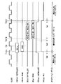
図3は、本実施の形態に係るメモリシステムの動作を示すタイミングチャートである。以下、この図に基づいて本実施の形態に係るメモリシステムの動作について説明する。説明の簡単のため、アドレス/コマンドバス11、データバス12RTCライン20のいずれにおける伝播遅延も等しくtpdとする。まず、初期状態ではメモリコントローラ10によるRTC信号(RTC)の出力は”0”であり、終端可変抵抗VRtのインピーダンスは書き込み用インピーダンスであるとする。
【0030】
そしてメモリシステムが読み出しモードになり、メモリコントローラ10はDIMMに対してデータの読み出しを行うとする。その場合、タイミングT1でメモリコントローラ10は、アドレス/コマンドバス11を介しDIMM内のDRAMへ読み出し指示の命令信号(CMD)”Read”を出力すると共に、読み出しの対象となるアドレスを指定するアドレス信号(不図示)を出力する。さらにそれと同時に、メモリコントローラ10はRTC信号(RTC)のレベルを”1”とし、RTCライン20を介して終端可変抵抗VRtへと出力する。
【0031】
タイミングT1でメモリコントローラ10より出力された命令信号”Read”は、伝播遅延tpdだけ遅れてタイミングT2でDRAMに到達する。また、RTC信号”1”もまた同じくタイミングT2で終端可変抵抗VRtに到達する。終端可変抵抗VRtは、RTC信号”1”を受けると、自身のインピーダンスを読み出し用インピーダンスに変化させる。
【0032】
一方、メモリコントローラ10からDRAMに到達した命令信号”Read”は、タイミングT2の直後で基準クロック信号が立ち上がるタイミングT3でDRAMに認識される。DRAMは命令信号”Read”を認識すると、所定のタイミングT4(図3の例では命令信号”Read”を認識したタイミングT3の2クロック後)で、アドレス信号により指定されたアドレスに記憶されているデータをデータバス12へと出力する。図3の例では、DRAMから連続して4ビットのデータRD0〜RD3が出力される。
【0033】
DRAMから出力された一連のデータRD0〜RD3は、伝播遅延tpdだけ遅れたタイミングT5からメモリコントローラ10に到達し始め、基準クロック信号に同期したタイミング(DQS信号のタイミング)でメモリコントローラ10に順次読み込まれる。このとき、メモリコントローラ10は最後のデータRD3がメモリコントローラ10によって読み込まれるタイミングT6までRTC信号”1”を保持し、その後”0”に戻す。そして、RTC信号”0”は伝播遅延tpdだけ遅れてタイミングT7で終端可変抵抗VRtに到達する。終端可変抵抗VRtは、RTC信号”0”を受けると、自身のインピーダンスを書き込み用インピーダンスに変化させる。
【0034】
図3から分かるように、終端可変抵抗VRtのインピーダンスは、タイミングT2〜T7の間は読み出し用インピーダンスとなる。つまり、DIMMに対して読み出しを行う間は、終端可変抵抗VRtのインピーダンスは読み出し用インピーダンスとなる。
【0035】
なお、図示は省略するが、読み出しモード以外の期間(書き込みモードやスタンバイ状態等の期間)では、メモリコントローラ10はRTC信号を”0”の値を維持し、終端可変抵抗VRtに書き込み用インピーダンスを維持させる。従って、メモリシステムが書き込みモードになり、メモリコントローラ10がDIMMに対してデータの書き込みを行う間は、終端可変抵抗VRtのインピーダンスは書き込み用インピーダンスとなる。
【0036】
以上のように、本実施の形態に係るデータバスよれば、終端可変抵抗VRtのインピーダンスは、読み出しモードの間は読み出し用インピーダンスとなり、それ以外の動作の間は書き込み用インピーダンスとなる。つまり、終端可変抵抗VRtのインピーダンスは、読み出しモードの間は読み出し用インピーダンスとなり、書き込みモードの間は書き込み用インピーダンスとなる。従って、読み出しモード、書き込みモードの動作モードを問わず、即ちデータの転送される方向を問わず、データバス12において信頼性の高いデータの転送が可能になる。
【0037】
なお、読み出しモード、書き込みモードのそれぞれの動作モードにおける終端可変抵抗VRtのインピーダンスの値は、例えば、実験やコンピュータシミュレーションによる解析によって得られる値や、所定の規格に基づいて得られる値等にすることが考えられる。但し、その決定の仕方は、それぞれの動作モードごとに終端抵抗を設ける目的によって異なる場合もある。
【0038】
例えば、読み出しモードおよび書き込みモードの両方で、反射による信号歪みを抑えることを目的とする場合は、それらの動作モード両方でインピーダンス整合がとれるように、終端可変抵抗VRtの読み出し用インピーダンスおよび書き込み用インピーダンスの値を決定すればよい。
【0039】
また例えば、読み出しモードにおいては信号波形の振幅を大きくして動作マージンを稼ぐことを主目的とし、書き込みモードにおいては反射による信号歪みを抑えることを主目的とする場合は、終端可変抵抗VRtにおける書き込み用インピーダンスの値はインピーダンス整合がとれる値、読み出し用インピーダンスの値は書き込み用インピーダンスよりも比較的大きめの値にそれぞれ決定すればよい。
【0040】
なお、本発明の適用は、図1に示した構成のメモリシステムに限定されるものではなく、双方向のデータ転送を担う信号線を有するデータバスを備えるあらゆるデータ転送システムに対して広く適用可能であることは明らかである。
【0041】
また、図4は実施の形態1に係るメモリシステムの変形例を示す図である。データバス12の信号線120の第1端には直列抵抗Rs1と共に、信号線120を終端する終端可変抵抗VRt2をさらに備えている。言い換えれば、終端素子は、信号線120の第2端に接続された終端可変抵抗VRt1および信号線120の第1端に接続された終端可変抵抗VRt2とを含む。終端可変抵抗VRt1,VRt2のそれぞれのインピーダンスは共にRTC信号により制御される。それ以外の構成は、図1に示したメモリシステムと同様である。
【0042】
上述したように、終端抵抗は信号線上において信号の受信側に近い位置に接続させる方が、受信側における信号歪みをより効果的に抑えることができるので、この変形例によれば図1に示したメモリシステムよりもさらに、読み出しモードにおける信号歪みを効果的に抑えることができる。
【0043】
<実施の形態2>
本実施の形態では、上記した実施の形態1における終端可変抵抗VRtの構成のより具体的な例を示す。本実施の形態におけるメモリシステム全体の構成および動作は、実施の形態1で説明した図1〜図3と同様であるのでここでの説明は省略する。
【0044】
ここでは上述した例のように、読み出しモードにおいては信号波形の振幅を大きくして動作マージンを稼ぐことを主目的とし、一方書き込みモードにおいては反射による信号歪みを抑えることを主目的とする場合を考える。この場合は、終端可変抵抗VRtにおける書き込み用インピーダンスの値として書き込み動作時にインピーダンス整合がとれる値、読み出し用インピーダンスの値として書き込み用インピーダンスよりも大きい値に決定すればよい。その場合、終端可変抵抗VRtは例えば図5に示すような構成とすることができる。
【0045】
図5において、抵抗R10は書き込み用インピーダンス(ここでは、書き込み動作時にインピーダンス整合がとれる抵抗値)を有すし、抵抗R11は所定のインピーダンス(抵抗値)を有し、リレーSW10はメモリコントローラ10からのRTC信号に応じて切り替わる。同図に示すように、リレーSW10はRTC信号が”1”(即ち、読み出し動作時)のとき抵抗R10を抵抗R11側に接続させ、RTC信号が”0”(即ち、読み出し動作時以外)のときは抵抗R10を直接データバス12の信号線120に接続させる。
【0046】
終端可変抵抗VRtのインピーダンスは、終端可変抵抗VRtを図5のように構成することで、書き込み動作時にはインピーダンス整合がとれる値になり、読み出し動作時には書き込み用インピーダンスよりも大きい値になる。よって、確実且つ容易に、読み出しモードで充分な動作マージンを得ることができる共に、書き込みモードの信号歪みを抑えることができる。
【0047】
また、この例からも明らかなように本発明に係るメモリシステムによれば、読み出しモードと書き込みモードとで終端抵抗によるそれぞれ異なる効果を得ることが可能である。
【0048】
<実施の形態3>
本実施の形態においては、メモリシステムにおける終端可変抵抗VRtの制御に係る動作の他の一例を示す。なお、本実施の形態に係るメモリシステムの構成は、図1および図2に示したものと同様であるので、ここでの詳細な説明は省略する。
【0049】
図6は、本実施の形態に係るメモリシステムの動作を示すタイミングチャートである。以下、この図に基づいて本実施の形態に係るメモリシステムの動作について説明する。まず、初期状態ではメモリコントローラ10によるRTC信号(RTC)の出力は”0”であり、終端可変抵抗VRtのインピーダンスは読み出し用インピーダンスであるとする。
【0050】
そして、メモリシステムが書き込みモードになり、メモリコントローラ10がDIMMに対してデータの書き込みを行う場合、タイミングT11でメモリコントローラ10は、アドレス/コマンドバス11を介しDIMM内のDRAMへ書き込み指示の命令信号(CMD)”Write”を出力すると共に、当該書き込みの対象となるアドレスを指定するアドレス信号(不図示)を出力する。さらにそれと同時に、メモリコントローラ10はRTC信号(RTC)のレベルを”1”とし、RTCライン20を介して終端可変抵抗VRtへと出力する。
【0051】
タイミングT11でメモリコントローラ10より出力された命令信号”Write”は、伝播遅延tpdだけ遅れてタイミングT12でDRAMに到達する。また、RTC信号”1”もまた同じくタイミングT12で終端可変抵抗VRtに到達する。終端可変抵抗VRtは、RTC信号”1”を受けると、自身のインピーダンスを書き込み用インピーダンスに変化させる。
【0052】
一方、メモリコントローラ10からDRAMに到達した命令信号”Write”は、タイミングT12の直後で基準クロックが立ち上がるタイミングT13でDRAMに認識される。メモリコントローラ10は命令信号”Write”を出力した後、さらに所定のタイミングT14で、書き込みを行うデータ(DQ)をデータバス12へと出力する。図6の例では、メモリコントローラ10から連続して4ビットのデータWD0〜WD3が出力される。
【0053】
メモリコントローラ10から出力された一連のデータWD0〜WD3は、伝播遅延tpdだけ遅れてタイミングT15からDIMM内のDRAMに到達し始める。DIMMは、基準クロック信号に同期したタイミング(DQS信号のタイミング)で一連のデータを読み取り、アドレス信号により指定されたアドレスに書き込む。このとき、メモリコントローラ10は最後のデータWD3の出力を終了するタイミングT16まではRTC信号”1”を保持し、その後”0”に戻す。そして、RTC信号”0”は伝播遅延tpdだけ遅れてタイミングT17で終端可変抵抗VRtに到達する。終端可変抵抗VRtは、RTC信号”0”を受けると、自身のインピーダンスを読み出し用インピーダンスに変化させる。
【0054】
図6から分かるように、終端可変抵抗VRtのインピーダンスは、タイミングT12〜T17の間書き込み用インピーダンスとなる。つまり、終端可変抵抗VRtのインピーダンスは、DRAMにおける書き込み動作の間は書き込み用インピーダンスとなる。
【0055】
なお、図示は省略するが、メモリシステムが書き込みモード以外の期間(例えば読み出しモードやスタンバイ状態等の期間)では、メモリコントローラ10はRTC信号として”0”の値を維持し、終端可変抵抗VRtは読み出し用インピーダンスを維持する。従って、メモリシステムが読み出しモードになり、メモリコントローラ10がDIMMに対してデータの読み出しを行う間は、終端可変抵抗VRtのインピーダンスの値は読み出し用インピーダンスとなる。
【0056】
以上のように、本実施の形態に係るデータバスによれば、終端可変抵抗VRtのインピーダンスは、書き込みモードの間は書き込み用インピーダンスとなり、それ以外の動作の間は読み出し用インピーダンスとなる。つまり、終端可変抵抗VRtのインピーダンスは、読み出しモードの間は読み出し用インピーダンスとなり、書き込みモードの間は書き込み用インピーダンスとなる。従って、読み出しモード、書き込みモードの動作モードを問わず、即ちデータが転送される方向を問わず、データバス12において信頼性の高いデータの転送が可能になる。
【0057】
<実施の形態4>
本実施の形態では、上記した実施の形態3における終端可変抵抗VRtの構成のより具体的な例を示す。本実施の形態におけるメモリシステム全体の構成は図1と同様であり、動作は図6と同様であるのでここでの説明は省略する。
【0058】
ここでも実施の形態2と同様に、読み出しモードにおいては信号波形の振幅を大きくして動作マージンを稼ぐことを主目的とし、一方書き込みモードにおいては反射による信号歪みを抑えることを主目的とする場合を考える。その場合、終端可変抵抗VRtは例えば図7に示すような構成とすることができる。
【0059】
図7においても、抵抗R10は書き込み用インピーダンス(ここでは、書き込み動作時にインピーダンス整合がとれる抵抗値)を有し、抵抗R11は所定のインピーダンスを有し、リレーSW10はメモリコントローラ10からのRTC信号に応じて切り替わる。この図から分かるように、本実施の形態に係る終端可変抵抗VRtの構成はほぼ図5と同様である。
【0060】
但し、実施の形態3ではメモリコントローラ10は書き込み動作時にRTC信号”1”を出力するので、リレーSW10の動作は実施の形態2と逆になる。即ちRTC信号が”1”(即ち、書き込み動作時)のとき抵抗R10を直接データバス12の信号線120に接続させ、RTC信号が0(即ち、書き込み動作時以外)のときは抵抗R10を抵抗R11側に接続させる。
【0061】
終端可変抵抗VRtを図7のように構成することで、終端可変抵抗VRtのインピーダンスは、書き込み動作時にはインピーダンス整合がとれる値になり、書き込み動作時には書き込み用インピーダンスよりも大きい値になる。よって、確実且つ容易に、読み出しモードで充分な動作マージンを得ることができる共に、書き込みモードでの信号歪みを抑えることができる。
【0062】
また、この例からも明らかなように本発明に係るメモリシステムによれば、読み出しモードと書き込みモードとで終端抵抗によるそれぞれ異なる効果を得ることが可能である。
【0063】
<実施の形態5>
図8は実施の形態5に係るメモリシステムの構成を示す図である。同図に示すように、データバス12の信号線120の第1端には直列抵抗Rs1と共に、信号線120を終端する終端可変抵抗VRt2をさらに備えている。言い換えれば、本実施の形態に係る終端素子は、信号線120の第2端に接続された終端可変抵抗VRt1および信号線120の第1端に接続された終端可変抵抗VRt2とを含む。
【0064】
本実施の形態においては、終端可変抵抗VRt1のインピーダンス(抵抗値)を制御するための第1のRTC信号RTC1と、終端可変抵抗VRt2のインピーダンス(抵抗値)を制御するための第2のRTC信号RTC2とが個別に与えられる。つまり、終端可変抵抗VRt1,VRt2とはそれぞれ個別に独立して制御される。例えば第1および第2のRTC信号RTC1,RTC2はメモリコントローラ10が出力し、図8に示すように終端可変抵抗VRt1とメモリコントローラ10との間は第1のRTC信号を伝達するための第1のRTCライン20aにより接続され、終端可変抵抗VRt2とメモリコントローラ10との間は、第2のRTC信号を伝達するための第2のRTCライン20bにより接続される。なお、それ以外の構成は、図1に示したメモリシステムと同様である。
【0065】
また、このメモリシステムの動作は、図3あるいは図7に示したものと同様であってもよい。その場合、第1のRTC信号と第2のRTC信号とは常に同じ値を出力することとなり、実質的に実施の形態1において図4に示したメモリシステムと同じ構成および動作となる。しかし、メモリコントローラ10が、終端可変抵抗VRt1,VRt2をそれぞれ独立して制御するので、以下に示すような動作も可能である。
【0066】
図9は、実施の形態5に係るメモリシステムの動作の一例を示すタイミングチャートである。同図から分かるように、第1のRTC信号RTC1の出力に関しては図3と同様の動作を行い、第2のRTC信号RTC2の出力に関しては図7と同様の動作を行う。即ち、終端可変抵抗VRt1のインピーダンスは、DIMMに対するデータの読み出し動作の間(タイミングT31〜T32の間)は読み出し用インピーダンスとなり、それ以外の動作の間は書き込み用インピーダンスとなる。一方、終端可変抵抗VRt2のインピーダンスは、DIMMに対するデータの書き込み動作の間(タイミングT33〜T34の間)は書き込み用インピーダンスとなり、それ以外の動作の間は読み出し用インピーダンスとなる。
【0067】
よって結果的に、終端可変抵抗VRt1,VRt2は、読み出し動作の間は共に読み出し用インピーダンスとなり、書き込み動作の間は共に書き込み用インピーダンスとなる。従って、読み出しモード、書き込みモードを問わず、データバス12において信頼性の高いデータの転送が可能になる。
【0068】
このように本実施の形態においては、終端可変抵抗VRt1,VRt2のインピーダンスをそれぞれ独立して個別に制御するので、制御方法の自由度が増す。また、終端可変抵抗VRt1,VRt2のインピーダンスの値の組み合わせにより、様々なインピーダンスの値を得ることも可能である。このことは、例えばメモリシステムが多機能化して、様々な周波数の信号の転送をデータバス12が担う必要が生じた場合に有効であると言える。
【0069】
<実施の形態6>
本実施の形態では、上記した実施の形態5における終端可変抵抗VRt1,VRt2の構成のより具体的な例を示す。本実施の形態において、メモリシステム全体としての構成は図8と同様であり、その動作は図9と同様であるとする。それらの図については、実施の形態5で説明したとおりであるのでここでの説明は省略する。
【0070】
図10は本実施の形態に係るメモリシステムにおける終端可変抵抗VRt1,VRt2の構成並びに動作を説明するための図である。同図に示すように、終端可変抵抗VRt1は、書き込み用インピーダンスを有する抵抗RwとリレーSW1とから成り、終端可変抵抗VRt2は読み出し用インピーダンスを有する抵抗RrとリレーSW2とから成る。リレーSW1は第1のRTC信号(RTC1)により制御されており、第1のRTC信号が”1”(書き込み動作時)のときON、”0”(書き込み動作時以外)のときOFFとなる。一方、リレーSW2は第2のRTC信号(RTC2)により制御されており、第2のRTC信号が”1”(読み出し動作時)のときON、”0”(読み出し動作時以外)のときOFFとなる。
【0071】
よって、DIMMに対する書き込み動作の間は、終端可変抵抗VRt1のインピーダンスは書き込み用インピーダンス、終端可変抵抗VRt2のインピーダンスは無限大となる。対して、読み出し動作の間は、終端可変抵抗VRt1のインピーダンスは無限大、終端可変抵抗VRt2のインピーダンスは読み出し用インピーダンスとなる。言い換えれば、書き込み動作の間は抵抗Rwのインピーダンスのみが機能し、読み出し動作の間は抵抗Rrのみが機能する。
【0072】
また、データバス12の信号線に対する終端可変抵抗VRt1の接続位置は終端可変抵抗VRt2の接続位置よりもDIMMの近くであり、一方、終端可変抵抗VRt2の接続位置は終端可変抵抗VRt1の接続位置よりもメモリコントローラ10の近くである。
【0073】
上述したように、終端抵抗は信号線上において信号の受信側に近い位置に接続させる方が、受信側における信号歪みをより効果的に抑えることができる。よって、本実施の形態によれば、書き込みモードではDIMMに入力される信号の歪みが効果的に抑えられ、読み出しモードではメモリコントローラ10に入力される信号の歪みを効果的に抑えられる。従って、実施の形態5よりも、読み出しモードおよび書き込みモードの信号歪みを効果的に抑えることができる。
【0074】
<実施の形態7>
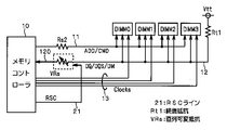
図11は実施の形態7に係るメモリシステムの構成を示す図である。同図に示すように、本実施の形態においては、図15に示された従来のメモリシステムに対し、直列抵抗Rs1を可変抵抗VRs(以下、「直列可変抵抗」と称する)に置換したメモリシステムについて説明する。つまり、データバス12の信号線120が備える終端抵抗は、直列可変抵抗VRsと終端抵抗Rtとから成る。また、直列可変抵抗VRsのインピーダンスは、外部から入力される制御信号(以下「RSC信号」と称する)により制御可能である。
【0075】
また、メモリコントローラ10はDIMMに対するデータの書き込みや読み出し動作の制御を行うことに加え、RSC信号を出力することにより直列可変抵抗VRsのインピーダンスを制御してもよい。このように、メモリコントローラ10が、直列可変抵抗VRsのインピーダンスを制御するインピーダンス制御部としての機能を備えることにより、言い換えれば、インピーダンス制御部をメモリコントローラ10に内蔵することにより、メモリシステムの小型化を図ることができる。RSC信号は、当該RSC信号を伝達するためのRSCライン21を介して直列可変抵抗VRsに入力される。
【0076】
ここで、説明の簡単のために図11での図示は省略したが、実際には図12のようにデータバス12の信号線のそれぞれに直列可変抵抗VRa1〜VRan(nは例えば108)が設けられる。また、以下の説明に用いる図においても、複数個の直列可変抵抗VRsを図11のように図面上1つにまとめて示す。
【0077】
なお、本実施の形態においてメモリコントローラ10がRSC信号により直列可変抵抗VRsのインピーダンスを制御する動作は、実施の形態1あるいは3において説明したRTC信号による終端可変抵抗VRsの制御動作と同様でよい。即ち、直列可変抵抗VRsのインピーダンスは、読み出し動作の間は読み出し用インピーダンスとなり、書き込み動作の間は書き込み用インピーダンスとなる。従って、読み出しモード、書き込みモードを問わず、データバス12において信頼性の高いデータの転送が可能になる。
【0078】
<実施の形態8>
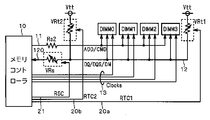
実施の形態7においては、データバス12の信号線120が備える終端抵抗のインピーダンスを固定値としたが、上記実施の形態1〜6に示したような終端可変抵抗とも組み合わせ可能である。例えば、図13は実施の形態1に係る終端可変抵抗VRtと組み合わせた場合の構成図であり、図14は実施の形態5に係る終端可変抵抗VRt1,VRt2と組み合わせた場合の構成図である。
【0079】
このような組み合わせにより、データバス12の信号線120が備える終端可変抵抗および直列可変抵抗のインピーダンスを、読み出し動作の間は読み出し用インピーダンスとし、書き込み動作の間は書き込み用インピーダンスとすることが可能になる。従って、読み出しモード、書き込みモードを問わず、データバス12において信頼性の高いデータの転送が可能になる。
【0080】
なお、例えば図14においては、直列可変抵抗VRsおよび終端可変抵抗VRt1、VRt2がそれぞれ、RSC信号および第1、第2のRTC信号によりそれぞれ独立して制御される例を示しているが、それら全てを単一の制御信号により制御するものであっても良い。それにより、インピーダンス制御部の機能を有するメモリコントローラ10の構成を簡略化でき、メモリシステムの小型化並びにコスト削減に寄与できる。
【0081】
逆に、メモリコントローラ10が直列可変抵抗VRsおよび終端可変抵抗VRt1、VRt2をそれぞれ独立して制御する場合は、制御方法の自由度が増すと共に、直列可変抵抗VRsおよび終端可変抵抗VRt1、VRt2のインピーダンスの値の組み合わせにより、様々なインピーダンスの値を得ることが可能になるという効果がある。
【0082】
【発明の効果】
請求項1に記載のデータバスによれば、データが転送される方向に応じて終端素子のインピーダンスを異なる値に設定し、各方向でのデータの転送を適切に行うことができる。
【0083】
請求項2に記載のデータバスによれば、データが転送される方向に応じて終端素子及び可変インピーダンス素子のインピーダンスを異なる値に設定し、各方向でのデータの転送を適切に行うことができる。
【0084】
請求項3に記載のデータバスによれば、データが転送される方向に応じて可変インピーダンス素子のインピーダンスを異なる値に設定し、各方向でのデータの転送を適切に行うことができる。
【0085】
請求項4に記載のデータバスによれば、第1の終端可変抵抗の抵抗値が、書き込みの際と読み出しの際とで、その各々の動作に適した値を採ることで、当該データバスは、読み出し、書き込みのいずれの動作においても、信頼性の高いデータの転送を可能とする。
【0086】
請求項5に記載のデータバスによれば、請求項4記載のデータバスにおいて、読み出しの際には第1の終端可変抵抗の抵抗値を大きくし、データを表す信号波形の振幅を大きくしてメモリコントローラの動作マージンを稼ぐ。他方、書き込みの際には第1の終端可変抵抗の抵抗値を小さくし、メモリに与えられる信号波形の歪みを抑制する。
【0087】
請求項6に記載のデータバスによれば、請求項4及び請求項5のいずれか一つに記載のデータバスにおいて、第2の終端可変抵抗の抵抗値が、書き込みの際と読み出しの際とで、その各々の動作に適した値を採ることで、当該データバスは、読み出し、書き込みのいずれの動作においても、信頼性の高いデータの転送を可能とする。
【0088】
請求項7に記載のデータバスによれば、請求項6記載のデータバスにおいて、書き込み際には第2の終端可変抵抗の値を無限大にすることで第1の終端可変抵抗の抵抗値のみを機能させ、メモリに与えられるデータを表す信号波形の歪みを効果的に抑制する。他方、読み出しの際には第1の終端可変抵抗の値を無限大にすることで第2の終端可変抵抗の抵抗値のみを機能させ、メモリコントローラに与えられる波形の歪みを抑制する。
【図面の簡単な説明】
【図1】実施の形態1に係るメモリシステムの構成を示す図である。
【図2】実施の形態1に係るメモリシステムの構成を示す図である。
【図3】実施の形態1に係るメモリシステムの動作を示すタイミングチャートである。
【図4】実施の形態1に係るメモリシステムの変形例を示す図である。
【図5】実施の形態2に係るメモリシステムにおける終端可変抵抗の構成の一例を示す図である。
【図6】実施の形態3に係るメモリシステムの動作を示すタイミングチャートである。
【図7】実施の形態4に係るメモリシステムにおける終端可変抵抗の構成の一例を示す図である。
【図8】実施の形態5に係るメモリシステムの構成を示す図である。
【図9】実施の形態5に係るメモリシステムの動作の一例を示すタイミングチャートである。
【図10】実施の形態6に係るメモリシステムにおける終端可変抵抗の構成の一例を示す図である。
【図11】実施の形態7に係るメモリシステムの構成を示す図である。
【図12】実施の形態7に係るメモリシステムの構成を示す図である。
【図13】実施の形態8に係るメモリシステムの構成を示す図である。
【図14】実施の形態8に係るメモリシステムの構成を示す図である。
【図15】従来のメモリシステムの構成を示す図である。
【図16】従来のメモリシステムの構成を示す図である。
【符号の説明】
10 メモリコントローラ、11 アドレス/コマンドバス、12 データバス、13 クロックライン、20,20a,20b RTCライン、21 RSCライン、Rt1,Rt2 終端抵抗、Rs1,Rs2 直列抵抗、VRt,VRt1,VRt2 終端可変抵抗、VRs 直列可変抵抗。[0001]
TECHNICAL FIELD OF THE INVENTION
The present invention relates to a technology for exchanging data using a data bus.
[0002]
[Prior art]
FIG. 15 and FIG. 16 are diagrams showing a configuration of a conventional memory system constructed on a motherboard of a computer system. Here, as an example of the memory system, a memory system including four DIMMs (Dual Inline Memory Modules) each including a DRAM (Dynamic Random Access Memory) is illustrated. As shown in FIG. 1, the
[0003]
The
[0004]
The
[0005]
The signals exchanged between the
[0006]
Further, the
[0007]
Here, the operation of the conventional memory system shown in FIG. 15 will be briefly described. For example, when writing data to a DIMM, first, the
[0008]
Conversely, when reading data from a DIMM, first, the
[0009]
By the way, if a reflection occurs at the time of transferring a data signal in a memory bus such as the address /
[0010]
For example, in FIG. 15, the
[0011]
Generally, when the terminating resistor is connected to a position closer to the receiving side of a signal to be transferred, signal distortion on the receiving side can be more effectively suppressed. As described above, since the
[0012]
In recent years, in order to increase the speed of operation of the memory system and reduce power consumption, the signal amplitude between the DIMM and the
[0013]
[Problems to be solved by the invention]
As in the case of the
[0014]
Therefore, for example, if a terminating resistor whose impedance is set so as to suppress signal distortion at the time of writing data to a DIMM is used, impedance matching at the time of reading is broken, and the waveform of the data signal at the time of reading is distorted. As a result, it is necessary to give a certain margin to the amplitude of the signal transferred on the
[0015]
The present invention has been made to solve the above problems, and in a memory system having a data bus that performs bidirectional data transfer, highly reliable data transfer can be performed regardless of the data transfer direction. It is intended to provide a possible data bus.
[0016]
[Means for Solving the Problems]
The data bus according to
[0017]
The data bus according to
[0018]
4. The data bus according to claim 3, further comprising: a signal line capable of bidirectionally transferring data, and a variable impedance element connected in series to the signal line, wherein the impedance of the variable impedance element is the data impedance. Is variable depending on the direction in which the data is transferred.
[0019]
The data bus according to claim 4 is the data bus according to
[0020]
The data bus according to claim 5, wherein in the data bus according to claim 4, a memory controller that transmits write data to the memory and receives read data from the memory is connected to the first end. The resistance value of the first terminating variable resistor is smaller at the time of writing than at the time of reading.
[0021]
7. The data bus according to claim 6, wherein the at least one terminal element is connected to the first end and the read / write operation is performed. And a second terminating variable resistor that adopts a different resistance value according to.
[0022]
The data bus according to claim 7, wherein in the data bus according to claim 6, a memory controller that transmits write data to the memory and receives read data from the memory is connected to the first end. Then, at the time of the writing, the resistance value of the second terminal variable resistor is set to infinity, and at the time of reading, the resistance value of the first terminal variable resistor is set to infinity.
[0023]
BEST MODE FOR CARRYING OUT THE INVENTION
<
FIG. 1 is a diagram showing a configuration of a memory system to which a data bus according to
[0024]
The impedance (resistance value) of the terminating variable resistor VRt can be controlled by a control signal (hereinafter referred to as “RTC signal”) input from the outside. For example, the
[0025]
Here, as described above, the
[0026]
In the following embodiment, each of the signal lines of the
[0027]
As described above, when the
[0028]
That is, the
[0029]
FIG. 3 is a timing chart showing the operation of the memory system according to the present embodiment. Hereinafter, the operation of the memory system according to the present embodiment will be described with reference to FIG. For the sake of simplicity, it is assumed that the propagation delay in any of the address /
[0030]
Then, the memory system enters the read mode, and the
[0031]
The command signal "Read" output from the
[0032]
On the other hand, the command signal “Read” that has reached the DRAM from the
[0033]
A series of data RD0 to RD3 output from the DRAM starts to reach the
[0034]
As can be seen from FIG. 3, the impedance of the terminating variable resistor VRt becomes the read impedance between the timings T2 and T7. That is, while reading is performed on the DIMM, the impedance of the terminating variable resistor VRt becomes the reading impedance.
[0035]
Although not shown, the
[0036]
As described above, according to the data bus according to the present embodiment, the impedance of the terminating variable resistor VRt becomes the read impedance during the read mode, and becomes the write impedance during other operations. That is, the impedance of the terminating variable resistor VRt becomes the read impedance during the read mode, and becomes the write impedance during the write mode. Therefore, regardless of the operation mode of the read mode and the write mode, that is, regardless of the direction in which the data is transferred, highly reliable data transfer on the
[0037]
Note that the impedance value of the terminating variable resistor VRt in each of the operation modes of the read mode and the write mode may be, for example, a value obtained by analysis by experiment or computer simulation, a value obtained based on a predetermined standard, or the like. Can be considered. However, the method of determination may differ depending on the purpose of providing a terminating resistor for each operation mode.
[0038]
For example, if the purpose is to suppress signal distortion due to reflection in both the read mode and the write mode, the read and write impedances of the terminating variable resistor VRt are adjusted so that impedance matching can be achieved in both of these operation modes. May be determined.
[0039]
For example, when the main purpose is to increase the amplitude of the signal waveform in the read mode to increase the operation margin, and to suppress the signal distortion due to reflection in the write mode, the writing in the termination variable resistor VRt is performed. The value of the impedance for use may be determined to be a value that can achieve impedance matching, and the value of the impedance for read may be determined to be a value relatively larger than the impedance for write.
[0040]
The application of the present invention is not limited to the memory system having the configuration shown in FIG. 1, but can be widely applied to any data transfer system including a data bus having a signal line for performing bidirectional data transfer. It is clear that
[0041]
FIG. 4 is a diagram showing a modification of the memory system according to the first embodiment. The first end of the
[0042]
As described above, when the terminating resistor is connected to a position closer to the signal receiving side on the signal line, signal distortion on the receiving side can be more effectively suppressed. Signal distortion in the read mode can be more effectively suppressed than in the memory system that uses the memory system.
[0043]
<
In the present embodiment, a more specific example of the configuration of the terminating variable resistor VRt in the first embodiment will be described. The configuration and operation of the entire memory system according to the present embodiment are the same as those shown in FIGS. 1 to 3 described in the first embodiment, and a description thereof will be omitted.
[0044]
Here, as in the above-described example, the case where the main purpose is to increase the amplitude of the signal waveform in the read mode to obtain an operation margin, while the main purpose is to suppress signal distortion due to reflection in the write mode Think. In this case, the value of the write impedance in the termination variable resistor VRt may be determined to be a value that allows impedance matching during a write operation, and the value of the read impedance may be determined to be a value larger than the write impedance. In that case, the terminating variable resistor VRt can be configured, for example, as shown in FIG.
[0045]
In FIG. 5, a resistor R10 has a writing impedance (here, a resistance value that allows impedance matching at the time of a writing operation), a resistor R11 has a predetermined impedance (resistance value), and a relay SW10 is provided from the
[0046]
By configuring the variable termination resistor VRt as shown in FIG. 5, the impedance of the variable termination resistor VRt becomes a value that enables impedance matching during a write operation and a value larger than the write impedance during a read operation. Therefore, a sufficient operation margin can be reliably and easily obtained in the read mode, and signal distortion in the write mode can be suppressed.
[0047]
Further, as is apparent from this example, according to the memory system of the present invention, it is possible to obtain different effects due to the terminating resistance in the read mode and the write mode.
[0048]
<Embodiment 3>
In the present embodiment, another example of the operation related to the control of the terminating variable resistor VRt in the memory system will be described. Note that the configuration of the memory system according to the present embodiment is the same as that shown in FIGS. 1 and 2, and a detailed description thereof will be omitted here.
[0049]
FIG. 6 is a timing chart showing the operation of the memory system according to the present embodiment. Hereinafter, the operation of the memory system according to the present embodiment will be described with reference to FIG. First, in the initial state, the output of the RTC signal (RTC) by the
[0050]
Then, when the memory system enters the write mode and the
[0051]
The command signal “Write” output from the
[0052]
On the other hand, the command signal “Write” that has reached the DRAM from the
[0053]
A series of data WD0 to WD3 output from the
[0054]
As can be seen from FIG. 6, the impedance of the terminating variable resistor VRt becomes the write impedance during the timing T12 to T17. That is, the impedance of the terminating variable resistor VRt becomes the write impedance during the write operation in the DRAM.
[0055]
Although not shown, during a period when the memory system is not in the write mode (for example, during a read mode or a standby state), the
[0056]
As described above, according to the data bus according to the present embodiment, the impedance of the terminating variable resistor VRt becomes the write impedance during the write mode, and becomes the read impedance during other operations. That is, the impedance of the terminating variable resistor VRt becomes the read impedance during the read mode, and becomes the write impedance during the write mode. Therefore, regardless of the operation mode of the read mode and the write mode, that is, regardless of the direction in which the data is transferred, highly reliable data transfer on the
[0057]
<Embodiment 4>
In the present embodiment, a more specific example of the configuration of the terminating variable resistor VRt in the above-described third embodiment will be described. The configuration of the entire memory system according to the present embodiment is the same as that of FIG. 1, and the operation is the same as that of FIG.
[0058]
Here, similarly to the second embodiment, in the read mode, the main purpose is to increase the amplitude of the signal waveform to increase the operation margin, while in the write mode, the main purpose is to suppress signal distortion due to reflection. think of. In that case, the terminating variable resistor VRt can be configured, for example, as shown in FIG.
[0059]
In FIG. 7 as well, the resistor R10 has a write impedance (here, a resistance value that allows impedance matching at the time of a write operation), the resistor R11 has a predetermined impedance, and the relay SW10 responds to an RTC signal from the
[0060]
However, in the third embodiment, since the
[0061]
By configuring the terminating variable resistor VRt as shown in FIG. 7, the impedance of the terminating variable resistor VRt becomes a value at which impedance matching can be achieved at the time of a write operation, and becomes larger than the write impedance at the time of a write operation. Therefore, a sufficient operation margin can be obtained reliably and easily in the read mode, and signal distortion in the write mode can be suppressed.
[0062]
Further, as is apparent from this example, according to the memory system of the present invention, it is possible to obtain different effects due to the terminating resistance in the read mode and the write mode.
[0063]
<Embodiment 5>
FIG. 8 is a diagram showing a configuration of a memory system according to the fifth embodiment. As shown in the figure, the first end of the
[0064]
In the present embodiment, a first RTC signal RTC1 for controlling the impedance (resistance value) of the termination variable resistor VRt1, and a second RTC signal for controlling the impedance (resistance value) of the termination variable resistor VRt2. RTC2 are provided separately. That is, the terminating variable resistors VRt1 and VRt2 are individually and independently controlled. For example, the first and second RTC signals RTC1 and RTC2 are output by the
[0065]
The operation of the memory system may be the same as that shown in FIG. 3 or FIG. In this case, the first RTC signal and the second RTC signal always output the same value, and have substantially the same configuration and operation as the memory system shown in FIG. 4 in the first embodiment. However, since the
[0066]
FIG. 9 is a timing chart showing an example of the operation of the memory system according to the fifth embodiment. As can be seen from the figure, the same operation as in FIG. 3 is performed for the output of the first RTC signal RTC1, and the same operation as in FIG. 7 is performed for the output of the second RTC signal RTC2. In other words, the impedance of the terminating variable resistor VRt1 becomes a read impedance during a data read operation on the DIMM (between timings T31 and T32), and becomes a write impedance during other operations. On the other hand, the impedance of the terminating variable resistor VRt2 becomes a write impedance during a data write operation to the DIMM (between timings T33 and T34), and becomes a read impedance during other operations.
[0067]
Therefore, as a result, the terminating variable resistors VRt1 and VRt2 both become the read impedance during the read operation, and both become the write impedance during the write operation. Therefore, regardless of the read mode and the write mode, highly reliable data transfer on the
[0068]
As described above, in the present embodiment, since the impedances of the terminating variable resistors VRt1 and VRt2 are controlled independently and individually, the degree of freedom of the control method is increased. Also, various impedance values can be obtained by combining the impedance values of the terminating variable resistors VRt1 and VRt2. This can be said to be effective, for example, when the memory system becomes multifunctional and the
[0069]
<Embodiment 6>
In the present embodiment, a more specific example of the configuration of the terminating variable resistors VRt1 and VRt2 in the above-described fifth embodiment will be described. In the present embodiment, the configuration of the entire memory system is the same as in FIG. 8, and the operation is the same as in FIG. These figures are as described in the fifth embodiment, and thus description thereof will be omitted.
[0070]
FIG. 10 is a diagram for explaining the configuration and operation of the terminating variable resistors VRt1 and VRt2 in the memory system according to the present embodiment. As shown in the figure, the terminating variable resistor VRt1 includes a resistor Rw having a writing impedance and a relay SW1, and the terminating variable resistor VRt2 includes a resistor Rr having a reading impedance and a relay SW2. The relay SW1 is controlled by a first RTC signal (RTC1), and is turned on when the first RTC signal is "1" (during a write operation) and turned off when it is "0" (other than a write operation). On the other hand, the relay SW2 is controlled by a second RTC signal (RTC2), and is turned ON when the second RTC signal is "1" (during a read operation) and OFF when the second RTC signal is "0" (during a read operation). Become.
[0071]
Therefore, during the write operation on the DIMM, the impedance of the terminating variable resistor VRt1 becomes the impedance for writing, and the impedance of the terminating variable resistor VRt2 becomes infinite. On the other hand, during the read operation, the impedance of the termination variable resistor VRt1 is infinite, and the impedance of the termination variable resistor VRt2 is the read impedance. In other words, only the impedance of the resistor Rw functions during the write operation, and only the resistor Rr functions during the read operation.
[0072]
The connection position of the termination variable resistor VRt1 to the signal line of the
[0073]
As described above, when the terminating resistor is connected to a position closer to the signal receiving side on the signal line, signal distortion on the receiving side can be more effectively suppressed. Therefore, according to the present embodiment, in the write mode, the distortion of the signal input to the DIMM is effectively suppressed, and in the read mode, the distortion of the signal input to the
[0074]
<Embodiment 7>
FIG. 11 is a diagram showing a configuration of a memory system according to the seventh embodiment. As shown in the figure, in the present embodiment, a memory system in which the series resistor Rs1 is replaced by a variable resistor VRs (hereinafter, referred to as “series variable resistor”) in the conventional memory system shown in FIG. Will be described. That is, the terminating resistor provided in the
[0075]
In addition, the
[0076]
Here, although illustration in FIG. 11 is omitted for the sake of simplicity, in practice, series variable resistors VRa1 to VRan (n is, for example, 108) are provided for each of the signal lines of the
[0077]
In this embodiment, the operation in which the
[0078]
<Embodiment 8>
In the seventh embodiment, the impedance of the terminating resistor provided in the
[0079]
With such a combination, it is possible to make the impedance of the terminating variable resistor and the series variable resistor included in the
[0080]
For example, FIG. 14 shows an example in which the series variable resistor VRs and the terminating variable resistors VRt1 and VRt2 are independently controlled by the RSC signal and the first and second RTC signals, respectively. May be controlled by a single control signal. Thus, the configuration of the
[0081]
Conversely, when the
[0082]
【The invention's effect】
According to the data bus of the first aspect, it is possible to set the impedance of the terminating element to a different value according to the direction in which data is transferred, and to appropriately perform data transfer in each direction.
[0083]
According to the data bus of the second aspect, it is possible to set the impedance of the terminating element and the variable impedance element to different values according to the direction in which the data is transferred, and to appropriately perform the data transfer in each direction. .
[0084]
According to the data bus of the third aspect, the impedance of the variable impedance element can be set to different values according to the direction in which data is transferred, and data can be appropriately transferred in each direction.
[0085]
According to the data bus of the fourth aspect, the resistance value of the first terminating variable resistor takes a value suitable for each operation at the time of writing and at the time of reading. In any of the read, write and write operations, highly reliable data transfer is enabled.
[0086]
According to the data bus of the fifth aspect, in the data bus of the fourth aspect, at the time of reading, the resistance value of the first terminating variable resistor is increased, and the amplitude of a signal waveform representing data is increased. Gain operating margin for memory controller. On the other hand, at the time of writing, the resistance value of the first terminating variable resistor is reduced to suppress the distortion of the signal waveform applied to the memory.
[0087]
According to the data bus described in claim 6, in the data bus according to any one of claims 4 and 5, the resistance value of the second terminating variable resistor is different between when writing and when reading. By adopting a value suitable for each operation, the data bus enables highly reliable data transfer in both read and write operations.
[0088]
According to the data bus of the seventh aspect, in the data bus of the sixth aspect, at the time of writing, the value of the second terminal variable resistor is set to infinity so that only the resistance value of the first terminal variable resistor is set. To effectively suppress the distortion of the signal waveform representing the data provided to the memory. On the other hand, at the time of reading, by making the value of the first terminating variable resistor infinite, only the resistance value of the second terminating variable resistor functions to suppress the distortion of the waveform given to the memory controller.
[Brief description of the drawings]
FIG. 1 is a diagram showing a configuration of a memory system according to a first embodiment.
FIG. 2 is a diagram showing a configuration of a memory system according to the first embodiment.
FIG. 3 is a timing chart illustrating an operation of the memory system according to the first embodiment;
FIG. 4 is a diagram showing a modification of the memory system according to the first embodiment;
FIG. 5 is a diagram illustrating an example of a configuration of a terminating variable resistor in a memory system according to a second embodiment;
FIG. 6 is a timing chart showing the operation of the memory system according to the third embodiment.
FIG. 7 is a diagram illustrating an example of a configuration of a terminating variable resistor in a memory system according to a fourth embodiment;
FIG. 8 is a diagram showing a configuration of a memory system according to a fifth embodiment.
FIG. 9 is a timing chart showing an example of the operation of the memory system according to the fifth embodiment.
FIG. 10 is a diagram showing an example of a configuration of a terminating variable resistor in a memory system according to a sixth embodiment.
FIG. 11 is a diagram showing a configuration of a memory system according to a seventh embodiment.
FIG. 12 is a diagram showing a configuration of a memory system according to a seventh embodiment.
FIG. 13 is a diagram showing a configuration of a memory system according to an eighth embodiment.
FIG. 14 is a diagram showing a configuration of a memory system according to an eighth embodiment.
FIG. 15 is a diagram showing a configuration of a conventional memory system.
FIG. 16 is a diagram showing a configuration of a conventional memory system.
[Explanation of symbols]
Claims (7)
前記信号線を終端する少なくとも一つの終端素子と
を備え、
前記少なくとも一つの終端素子のインピーダンスは、前記データが転送される方向に応じて可変であるデータバス。A signal line that can transfer data in both directions,
And at least one termination element that terminates the signal line,
A data bus, wherein an impedance of the at least one terminating element is variable according to a direction in which the data is transferred.
を更に備え、
前記可変インピーダンス素子のインピーダンスは、前記データが転送される方向に応じて可変である請求項1記載のデータバス。Further comprising a variable impedance element connected in series to the signal line,
2. The data bus according to claim 1, wherein the impedance of the variable impedance element is variable according to a direction in which the data is transferred.
前記信号線に対して直列に接続された可変インピーダンス素子と
を備え、
前記可変インピーダンス素子のインピーダンスは、前記データが転送される方向に応じて可変であるデータバス。A signal line that can transfer data in both directions,
A variable impedance element connected in series to the signal line,
A data bus wherein the impedance of the variable impedance element is variable according to a direction in which the data is transferred.
前記少なくとも一つの第3端の各々には前記データの読み出し/書き込みが可能なメモリが接続され、
前記少なくとも一つの終端素子は、前記第2端に接続されて前記読み出し/書き込み動作に応じて異なる抵抗値を採る第1の終端可変抵抗を有する、請求項1及び請求項2のいずれか一つに記載のデータバス。The signal line has a first end and a second end, and at least one third end branched from between the first end and the second end,
A memory capable of reading / writing the data is connected to each of the at least one third end,
3. The device according to claim 1, wherein the at least one terminating element includes a first terminating variable resistor connected to the second end and having a different resistance value according to the read / write operation. Data bus as described in.
前記書き込みの際には前記読み出しの際よりも、前記第1の終端可変抵抗の抵抗値が小さい、請求項4記載のデータバス。A memory controller that transmits write data to the memory and receives read data from the memory is connected to the first end,
5. The data bus according to claim 4, wherein a resistance value of said first terminating variable resistor is smaller in said writing than in said reading.
前記書き込みの際には前記第2の終端可変抵抗の抵抗値を無限大にし、前記読み出しの際には前記第1の終端可変抵抗の抵抗値を無限大にする、請求項6記載のデータバス。A memory controller that transmits write data to the memory and receives read data from the memory is connected to the first end,
7. The data bus according to claim 6, wherein the resistance value of the second termination variable resistor is set to infinity during the writing, and the resistance value of the first termination variable resistor is set to infinity during the reading. .
Priority Applications (2)
| Application Number | Priority Date | Filing Date | Title |
|---|---|---|---|
| JP2002179969A JP2004021916A (en) | 2002-06-20 | 2002-06-20 | Data bus |
| US10/299,712 US6844754B2 (en) | 2002-06-20 | 2002-11-20 | Data bus |
Applications Claiming Priority (1)
| Application Number | Priority Date | Filing Date | Title |
|---|---|---|---|
| JP2002179969A JP2004021916A (en) | 2002-06-20 | 2002-06-20 | Data bus |
Publications (2)
| Publication Number | Publication Date |
|---|---|
| JP2004021916A true JP2004021916A (en) | 2004-01-22 |
| JP2004021916A5 JP2004021916A5 (en) | 2005-10-20 |
Family
ID=29728235
Family Applications (1)
| Application Number | Title | Priority Date | Filing Date |
|---|---|---|---|
| JP2002179969A Pending JP2004021916A (en) | 2002-06-20 | 2002-06-20 | Data bus |
Country Status (2)
| Country | Link |
|---|---|
| US (1) | US6844754B2 (en) |
| JP (1) | JP2004021916A (en) |
Cited By (4)
| Publication number | Priority date | Publication date | Assignee | Title |
|---|---|---|---|---|
| KR100798739B1 (en) | 2006-09-27 | 2008-01-29 | 주식회사 하이닉스반도체 | Semiconductor memory device and the driving method thereof |
| JP2009540633A (en) * | 2006-06-02 | 2009-11-19 | ラムバス・インコーポレーテッド | Integrated circuit with gradual on-die termination |
| JP5752862B1 (en) * | 2014-06-18 | 2015-07-22 | ゼンテルジャパン株式会社 | Semiconductor circuit device and semiconductor memory system |
| US9536604B1 (en) | 2016-01-06 | 2017-01-03 | International Business Machines Corporation | Impedance matching system for DDR memory |
Families Citing this family (52)
| Publication number | Priority date | Publication date | Assignee | Title |
|---|---|---|---|---|
| TW521187B (en) * | 2001-10-05 | 2003-02-21 | Via Tech Inc | Signal compensation circuit of bus |
| US7088170B2 (en) * | 2003-06-30 | 2006-08-08 | International Business Machines Corporation | Multiplexer and demultiplexer |
| US20060132577A1 (en) * | 2004-12-04 | 2006-06-22 | Hon Hai Precision Industry Co., Ltd. | Circuit topology for high-speed printed circuit board |
| CN1828478A (en) * | 2005-03-05 | 2006-09-06 | 鸿富锦精密工业(深圳)有限公司 | Main board double data rate power supply circuit |
| US8089795B2 (en) | 2006-02-09 | 2012-01-03 | Google Inc. | Memory module with memory stack and interface with enhanced capabilities |
| US8081474B1 (en) | 2007-12-18 | 2011-12-20 | Google Inc. | Embossed heat spreader |
| US8244971B2 (en) | 2006-07-31 | 2012-08-14 | Google Inc. | Memory circuit system and method |
| US8041881B2 (en) | 2006-07-31 | 2011-10-18 | Google Inc. | Memory device with emulated characteristics |
| US8077535B2 (en) | 2006-07-31 | 2011-12-13 | Google Inc. | Memory refresh apparatus and method |
| US8438328B2 (en) | 2008-02-21 | 2013-05-07 | Google Inc. | Emulation of abstracted DIMMs using abstracted DRAMs |
| US8060774B2 (en) | 2005-06-24 | 2011-11-15 | Google Inc. | Memory systems and memory modules |
| US9171585B2 (en) | 2005-06-24 | 2015-10-27 | Google Inc. | Configurable memory circuit system and method |
| US10013371B2 (en) | 2005-06-24 | 2018-07-03 | Google Llc | Configurable memory circuit system and method |
| US8327104B2 (en) | 2006-07-31 | 2012-12-04 | Google Inc. | Adjusting the timing of signals associated with a memory system |
| US8111566B1 (en) | 2007-11-16 | 2012-02-07 | Google, Inc. | Optimal channel design for memory devices for providing a high-speed memory interface |
| US8386722B1 (en) | 2008-06-23 | 2013-02-26 | Google Inc. | Stacked DIMM memory interface |
| US8055833B2 (en) | 2006-10-05 | 2011-11-08 | Google Inc. | System and method for increasing capacity, performance, and flexibility of flash storage |
| US8397013B1 (en) | 2006-10-05 | 2013-03-12 | Google Inc. | Hybrid memory module |
| US8796830B1 (en) | 2006-09-01 | 2014-08-05 | Google Inc. | Stackable low-profile lead frame package |
| US9542352B2 (en) * | 2006-02-09 | 2017-01-10 | Google Inc. | System and method for reducing command scheduling constraints of memory circuits |
| US20080126690A1 (en) * | 2006-02-09 | 2008-05-29 | Rajan Suresh N | Memory module with memory stack |
| US8359187B2 (en) | 2005-06-24 | 2013-01-22 | Google Inc. | Simulating a different number of memory circuit devices |
| US20080082763A1 (en) | 2006-10-02 | 2008-04-03 | Metaram, Inc. | Apparatus and method for power management of memory circuits by a system or component thereof |
| US7386656B2 (en) | 2006-07-31 | 2008-06-10 | Metaram, Inc. | Interface circuit system and method for performing power management operations in conjunction with only a portion of a memory circuit |
| US8130560B1 (en) | 2006-11-13 | 2012-03-06 | Google Inc. | Multi-rank partial width memory modules |
| US9507739B2 (en) | 2005-06-24 | 2016-11-29 | Google Inc. | Configurable memory circuit system and method |
| US8335894B1 (en) * | 2008-07-25 | 2012-12-18 | Google Inc. | Configurable memory system with interface circuit |
| US8090897B2 (en) | 2006-07-31 | 2012-01-03 | Google Inc. | System and method for simulating an aspect of a memory circuit |
| US20080028136A1 (en) | 2006-07-31 | 2008-01-31 | Schakel Keith R | Method and apparatus for refresh management of memory modules |
| CN100518436C (en) * | 2005-08-05 | 2009-07-22 | 鸿富锦精密工业(深圳)有限公司 | Cabling configuration for transmission line in high-speed printed circuit board |
| KR101303518B1 (en) | 2005-09-02 | 2013-09-03 | 구글 인코포레이티드 | Methods and apparatus of stacking drams |
| US7372293B2 (en) * | 2005-12-07 | 2008-05-13 | Intel Corporation | Polarity driven dynamic on-die termination |
| US9632929B2 (en) | 2006-02-09 | 2017-04-25 | Google Inc. | Translating an address associated with a command communicated between a system and memory circuits |
| US20070205805A1 (en) * | 2006-03-03 | 2007-09-06 | Oliver Kiehl | Electrical system including driver that provides a first drive strength and a second drive strength |
| US7479799B2 (en) * | 2006-03-14 | 2009-01-20 | Inphi Corporation | Output buffer with switchable output impedance |
| KR100780949B1 (en) * | 2006-03-21 | 2007-12-03 | 삼성전자주식회사 | Semiconductor memory device testing on/off state of ODT circuit in the data read mode and test method of the state of ODT circuit |
| US20070247185A1 (en) * | 2006-03-30 | 2007-10-25 | Hideo Oie | Memory system with dynamic termination |
| US7724589B2 (en) | 2006-07-31 | 2010-05-25 | Google Inc. | System and method for delaying a signal communicated from a system to at least one of a plurality of memory circuits |
| US20080025136A1 (en) * | 2006-07-31 | 2008-01-31 | Metaram, Inc. | System and method for storing at least a portion of information received in association with a first operation for use in performing a second operation |
| US20080162801A1 (en) * | 2006-12-29 | 2008-07-03 | Ripan Das | Series termination for a low power memory interface |
| US20080197877A1 (en) * | 2007-02-16 | 2008-08-21 | Intel Corporation | Per byte lane dynamic on-die termination |
| US20090091963A1 (en) * | 2007-10-04 | 2009-04-09 | Advanced Micro Devices, Inc. | Memory device |
| TW200921595A (en) * | 2007-11-14 | 2009-05-16 | Darfon Electronics Corp | Multi-lamp backlight apparatus |
| JP5217520B2 (en) * | 2008-03-06 | 2013-06-19 | 株式会社リコー | Electronics |
| US8041865B2 (en) * | 2008-08-04 | 2011-10-18 | Qimonda Ag | Bus termination system and method |
| US7915912B2 (en) | 2008-09-24 | 2011-03-29 | Rambus Inc. | Signal lines with internal and external termination |
| WO2010144624A1 (en) | 2009-06-09 | 2010-12-16 | Google Inc. | Programming of dimm termination resistance values |
| KR20110076481A (en) * | 2009-12-29 | 2011-07-06 | 삼성전자주식회사 | Memory module and memory system having the same |
| US10380060B2 (en) * | 2016-06-17 | 2019-08-13 | Etron Technology, Inc. | Low-pincount high-bandwidth memory and memory bus |
| US10340022B2 (en) * | 2017-05-16 | 2019-07-02 | Samsung Electronics Co., Ltd. | Nonvolatile memory including on-die-termination circuit and storage device including the nonvolatile memory |
| KR102471160B1 (en) * | 2017-05-16 | 2022-11-25 | 삼성전자주식회사 | Nonvolatile memory including on-die-termination circuit and Storage device including the nonvolatile memory |
| US10528515B2 (en) * | 2017-06-27 | 2020-01-07 | Intel Corporation | Memory channel driver with echo cancellation |
Family Cites Families (6)
| Publication number | Priority date | Publication date | Assignee | Title |
|---|---|---|---|---|
| US5467455A (en) * | 1993-11-03 | 1995-11-14 | Motorola, Inc. | Data processing system and method for performing dynamic bus termination |
| JPH08194034A (en) | 1995-01-19 | 1996-07-30 | Hitachi Ltd | Semiconductor testing device |
| EP1050824A3 (en) * | 1999-04-22 | 2004-01-28 | Matsushita Electric Industrial Co., Ltd. | Bidirectional signal transmission circuit and bus system |
| JP2001177580A (en) | 1999-12-20 | 2001-06-29 | Sony Corp | Impedance adapting system |
| US6356106B1 (en) * | 2000-09-12 | 2002-03-12 | Micron Technology, Inc. | Active termination in a multidrop memory system |
| US6690191B2 (en) * | 2001-12-21 | 2004-02-10 | Sun Microsystems, Inc. | Bi-directional output buffer |
-
2002
- 2002-06-20 JP JP2002179969A patent/JP2004021916A/en active Pending
- 2002-11-20 US US10/299,712 patent/US6844754B2/en not_active Expired - Fee Related
Cited By (6)
| Publication number | Priority date | Publication date | Assignee | Title |
|---|---|---|---|---|
| JP2009540633A (en) * | 2006-06-02 | 2009-11-19 | ラムバス・インコーポレーテッド | Integrated circuit with gradual on-die termination |
| KR100798739B1 (en) | 2006-09-27 | 2008-01-29 | 주식회사 하이닉스반도체 | Semiconductor memory device and the driving method thereof |
| US7710797B2 (en) | 2006-09-27 | 2010-05-04 | Hynix Semiconductors, Inc. | Semiconductor memory device and method for driving the same |
| JP5752862B1 (en) * | 2014-06-18 | 2015-07-22 | ゼンテルジャパン株式会社 | Semiconductor circuit device and semiconductor memory system |
| WO2015193992A1 (en) * | 2014-06-18 | 2015-12-23 | ゼンテルジャパン株式会社 | Semiconductor circuit device and semiconductor memory system |
| US9536604B1 (en) | 2016-01-06 | 2017-01-03 | International Business Machines Corporation | Impedance matching system for DDR memory |
Also Published As
| Publication number | Publication date |
|---|---|
| US20030234664A1 (en) | 2003-12-25 |
| US6844754B2 (en) | 2005-01-18 |
Similar Documents
| Publication | Publication Date | Title |
|---|---|---|
| JP2004021916A (en) | Data bus | |
| KR100492101B1 (en) | Memory device and memory system | |
| US6532525B1 (en) | Method and apparatus for accessing memory | |
| US7342411B2 (en) | Dynamic on-die termination launch latency reduction | |
| US7058776B2 (en) | Asynchronous memory using source synchronous transfer and system employing the same | |
| US20010054135A1 (en) | Memory control technique | |
| US9507738B2 (en) | Method and system for synchronizing address and control signals in threaded memory modules | |
| KR100888597B1 (en) | Apparatus and methods for controlling memory interface | |
| CN107103927B (en) | Memory system, memory module and control method thereof | |
| JP2007335528A (en) | Laminated semiconductor device | |
| US20170287538A1 (en) | Flexible point-to-point memory topology | |
| US20060233031A1 (en) | Synchronous RAM memory circuit | |
| US6502173B1 (en) | System for accessing memory and method therefore | |
| KR100499416B1 (en) | Data input device of DDR SDRAM | |
| US20090013144A1 (en) | Integrated circuit, and integrated circuit system | |
| JP2004334879A (en) | Memory system, and method therefor | |
| US20030218918A1 (en) | Data writing method and memory system for using the method | |
| JP2005310153A (en) | Memory device | |
| EP3819778A1 (en) | Bus system and method for operating a bus system | |
| JP2008251060A (en) | Semiconductor memory device | |
| EP0926684B1 (en) | Synchronisation device for synchronous dynamic random-access memory | |
| JP5130754B2 (en) | Semiconductor integrated circuit and memory system | |
| US20010044871A1 (en) | CPU system with high-speed peripheral LSI circuit | |
| TW202403740A (en) | Data transmission apparatus and method having clock gating mechanism | |
| KR20140029708A (en) | Semiconductor device and operating method thereof |
Legal Events
| Date | Code | Title | Description |
|---|---|---|---|
| A521 | Request for written amendment filed |
Free format text: JAPANESE INTERMEDIATE CODE: A523 Effective date: 20050614 |
|
| A621 | Written request for application examination |
Free format text: JAPANESE INTERMEDIATE CODE: A621 Effective date: 20050614 |
|
| A977 | Report on retrieval |
Free format text: JAPANESE INTERMEDIATE CODE: A971007 Effective date: 20080304 |
|
| A131 | Notification of reasons for refusal |
Free format text: JAPANESE INTERMEDIATE CODE: A131 Effective date: 20080325 |
|
| A521 | Request for written amendment filed |
Free format text: JAPANESE INTERMEDIATE CODE: A523 Effective date: 20080519 |
|
| RD04 | Notification of resignation of power of attorney |
Free format text: JAPANESE INTERMEDIATE CODE: A7424 Effective date: 20080519 |
|
| A131 | Notification of reasons for refusal |
Free format text: JAPANESE INTERMEDIATE CODE: A131 Effective date: 20090414 |
|
| A02 | Decision of refusal |
Free format text: JAPANESE INTERMEDIATE CODE: A02 Effective date: 20090901 |