JP2004017865A - Vehicle traveling control device - Google Patents
Vehicle traveling control device Download PDFInfo
- Publication number
- JP2004017865A JP2004017865A JP2002177663A JP2002177663A JP2004017865A JP 2004017865 A JP2004017865 A JP 2004017865A JP 2002177663 A JP2002177663 A JP 2002177663A JP 2002177663 A JP2002177663 A JP 2002177663A JP 2004017865 A JP2004017865 A JP 2004017865A
- Authority
- JP
- Japan
- Prior art keywords
- vehicle
- acceleration
- upper limit
- automatic braking
- creep
- Prior art date
- Legal status (The legal status is an assumption and is not a legal conclusion. Google has not performed a legal analysis and makes no representation as to the accuracy of the status listed.)
- Granted
Links
- 230000001133 acceleration Effects 0.000 claims abstract description 73
- 238000001514 detection method Methods 0.000 abstract description 3
- 239000000446 fuel Substances 0.000 description 3
- 230000005540 biological transmission Effects 0.000 description 2
- 230000007246 mechanism Effects 0.000 description 2
- 238000000034 method Methods 0.000 description 2
- 230000008569 process Effects 0.000 description 2
- 230000008878 coupling Effects 0.000 description 1
- 238000010168 coupling process Methods 0.000 description 1
- 238000005859 coupling reaction Methods 0.000 description 1
- 230000003111 delayed effect Effects 0.000 description 1
- 230000000994 depressogenic effect Effects 0.000 description 1
- 238000010586 diagram Methods 0.000 description 1
- 230000000694 effects Effects 0.000 description 1
- 230000002349 favourable effect Effects 0.000 description 1
- 239000012530 fluid Substances 0.000 description 1
- 230000006872 improvement Effects 0.000 description 1
- 239000000203 mixture Substances 0.000 description 1
- 238000010248 power generation Methods 0.000 description 1
- 230000001172 regenerating effect Effects 0.000 description 1
- 230000006641 stabilisation Effects 0.000 description 1
- 238000011105 stabilization Methods 0.000 description 1
Images

Classifications
-
- B—PERFORMING OPERATIONS; TRANSPORTING
- B60—VEHICLES IN GENERAL
- B60W—CONJOINT CONTROL OF VEHICLE SUB-UNITS OF DIFFERENT TYPE OR DIFFERENT FUNCTION; CONTROL SYSTEMS SPECIALLY ADAPTED FOR HYBRID VEHICLES; ROAD VEHICLE DRIVE CONTROL SYSTEMS FOR PURPOSES NOT RELATED TO THE CONTROL OF A PARTICULAR SUB-UNIT
- B60W10/00—Conjoint control of vehicle sub-units of different type or different function
- B60W10/04—Conjoint control of vehicle sub-units of different type or different function including control of propulsion units
- B60W10/06—Conjoint control of vehicle sub-units of different type or different function including control of propulsion units including control of combustion engines
-
- B—PERFORMING OPERATIONS; TRANSPORTING
- B60—VEHICLES IN GENERAL
- B60K—ARRANGEMENT OR MOUNTING OF PROPULSION UNITS OR OF TRANSMISSIONS IN VEHICLES; ARRANGEMENT OR MOUNTING OF PLURAL DIVERSE PRIME-MOVERS IN VEHICLES; AUXILIARY DRIVES FOR VEHICLES; INSTRUMENTATION OR DASHBOARDS FOR VEHICLES; ARRANGEMENTS IN CONNECTION WITH COOLING, AIR INTAKE, GAS EXHAUST OR FUEL SUPPLY OF PROPULSION UNITS IN VEHICLES
- B60K31/00—Vehicle fittings, acting on a single sub-unit only, for automatically controlling vehicle speed, i.e. preventing speed from exceeding an arbitrarily established velocity or maintaining speed at a particular velocity, as selected by the vehicle operator
- B60K31/02—Vehicle fittings, acting on a single sub-unit only, for automatically controlling vehicle speed, i.e. preventing speed from exceeding an arbitrarily established velocity or maintaining speed at a particular velocity, as selected by the vehicle operator including electrically actuated servomechanism including an electric control system or a servomechanism in which the vehicle velocity affecting element is actuated electrically
- B60K31/04—Vehicle fittings, acting on a single sub-unit only, for automatically controlling vehicle speed, i.e. preventing speed from exceeding an arbitrarily established velocity or maintaining speed at a particular velocity, as selected by the vehicle operator including electrically actuated servomechanism including an electric control system or a servomechanism in which the vehicle velocity affecting element is actuated electrically and means for comparing one electrical quantity, e.g. voltage, pulse, waveform, flux, or the like, with another quantity of a like kind, which comparison means is involved in the development of an electrical signal which is fed into the controlling means
-
- B—PERFORMING OPERATIONS; TRANSPORTING
- B60—VEHICLES IN GENERAL
- B60T—VEHICLE BRAKE CONTROL SYSTEMS OR PARTS THEREOF; BRAKE CONTROL SYSTEMS OR PARTS THEREOF, IN GENERAL; ARRANGEMENT OF BRAKING ELEMENTS ON VEHICLES IN GENERAL; PORTABLE DEVICES FOR PREVENTING UNWANTED MOVEMENT OF VEHICLES; VEHICLE MODIFICATIONS TO FACILITATE COOLING OF BRAKES
- B60T7/00—Brake-action initiating means
- B60T7/12—Brake-action initiating means for automatic initiation; for initiation not subject to will of driver or passenger
-
- B—PERFORMING OPERATIONS; TRANSPORTING
- B60—VEHICLES IN GENERAL
- B60W—CONJOINT CONTROL OF VEHICLE SUB-UNITS OF DIFFERENT TYPE OR DIFFERENT FUNCTION; CONTROL SYSTEMS SPECIALLY ADAPTED FOR HYBRID VEHICLES; ROAD VEHICLE DRIVE CONTROL SYSTEMS FOR PURPOSES NOT RELATED TO THE CONTROL OF A PARTICULAR SUB-UNIT
- B60W10/00—Conjoint control of vehicle sub-units of different type or different function
- B60W10/04—Conjoint control of vehicle sub-units of different type or different function including control of propulsion units
-
- B—PERFORMING OPERATIONS; TRANSPORTING
- B60—VEHICLES IN GENERAL
- B60W—CONJOINT CONTROL OF VEHICLE SUB-UNITS OF DIFFERENT TYPE OR DIFFERENT FUNCTION; CONTROL SYSTEMS SPECIALLY ADAPTED FOR HYBRID VEHICLES; ROAD VEHICLE DRIVE CONTROL SYSTEMS FOR PURPOSES NOT RELATED TO THE CONTROL OF A PARTICULAR SUB-UNIT
- B60W10/00—Conjoint control of vehicle sub-units of different type or different function
- B60W10/18—Conjoint control of vehicle sub-units of different type or different function including control of braking systems
-
- B—PERFORMING OPERATIONS; TRANSPORTING
- B60—VEHICLES IN GENERAL
- B60W—CONJOINT CONTROL OF VEHICLE SUB-UNITS OF DIFFERENT TYPE OR DIFFERENT FUNCTION; CONTROL SYSTEMS SPECIALLY ADAPTED FOR HYBRID VEHICLES; ROAD VEHICLE DRIVE CONTROL SYSTEMS FOR PURPOSES NOT RELATED TO THE CONTROL OF A PARTICULAR SUB-UNIT
- B60W30/00—Purposes of road vehicle drive control systems not related to the control of a particular sub-unit, e.g. of systems using conjoint control of vehicle sub-units
- B60W30/14—Adaptive cruise control
- B60W30/143—Speed control
- B60W30/146—Speed limiting
-
- B—PERFORMING OPERATIONS; TRANSPORTING
- B60—VEHICLES IN GENERAL
- B60W—CONJOINT CONTROL OF VEHICLE SUB-UNITS OF DIFFERENT TYPE OR DIFFERENT FUNCTION; CONTROL SYSTEMS SPECIALLY ADAPTED FOR HYBRID VEHICLES; ROAD VEHICLE DRIVE CONTROL SYSTEMS FOR PURPOSES NOT RELATED TO THE CONTROL OF A PARTICULAR SUB-UNIT
- B60W30/00—Purposes of road vehicle drive control systems not related to the control of a particular sub-unit, e.g. of systems using conjoint control of vehicle sub-units
- B60W30/18—Propelling the vehicle
- B60W30/18009—Propelling the vehicle related to particular drive situations
- B60W30/18063—Creeping
-
- B—PERFORMING OPERATIONS; TRANSPORTING
- B60—VEHICLES IN GENERAL
- B60W—CONJOINT CONTROL OF VEHICLE SUB-UNITS OF DIFFERENT TYPE OR DIFFERENT FUNCTION; CONTROL SYSTEMS SPECIALLY ADAPTED FOR HYBRID VEHICLES; ROAD VEHICLE DRIVE CONTROL SYSTEMS FOR PURPOSES NOT RELATED TO THE CONTROL OF A PARTICULAR SUB-UNIT
- B60W30/00—Purposes of road vehicle drive control systems not related to the control of a particular sub-unit, e.g. of systems using conjoint control of vehicle sub-units
- B60W30/18—Propelling the vehicle
- B60W30/1819—Propulsion control with control means using analogue circuits, relays or mechanical links
-
- B—PERFORMING OPERATIONS; TRANSPORTING
- B60—VEHICLES IN GENERAL
- B60W—CONJOINT CONTROL OF VEHICLE SUB-UNITS OF DIFFERENT TYPE OR DIFFERENT FUNCTION; CONTROL SYSTEMS SPECIALLY ADAPTED FOR HYBRID VEHICLES; ROAD VEHICLE DRIVE CONTROL SYSTEMS FOR PURPOSES NOT RELATED TO THE CONTROL OF A PARTICULAR SUB-UNIT
- B60W2520/00—Input parameters relating to overall vehicle dynamics
- B60W2520/10—Longitudinal speed
- B60W2520/105—Longitudinal acceleration
-
- B—PERFORMING OPERATIONS; TRANSPORTING
- B60—VEHICLES IN GENERAL
- B60W—CONJOINT CONTROL OF VEHICLE SUB-UNITS OF DIFFERENT TYPE OR DIFFERENT FUNCTION; CONTROL SYSTEMS SPECIALLY ADAPTED FOR HYBRID VEHICLES; ROAD VEHICLE DRIVE CONTROL SYSTEMS FOR PURPOSES NOT RELATED TO THE CONTROL OF A PARTICULAR SUB-UNIT
- B60W2710/00—Output or target parameters relating to a particular sub-units
- B60W2710/06—Combustion engines, Gas turbines
- B60W2710/0644—Engine speed
- B60W2710/065—Idle condition
-
- B—PERFORMING OPERATIONS; TRANSPORTING
- B60—VEHICLES IN GENERAL
- B60W—CONJOINT CONTROL OF VEHICLE SUB-UNITS OF DIFFERENT TYPE OR DIFFERENT FUNCTION; CONTROL SYSTEMS SPECIALLY ADAPTED FOR HYBRID VEHICLES; ROAD VEHICLE DRIVE CONTROL SYSTEMS FOR PURPOSES NOT RELATED TO THE CONTROL OF A PARTICULAR SUB-UNIT
- B60W2720/00—Output or target parameters relating to overall vehicle dynamics
- B60W2720/10—Longitudinal speed
- B60W2720/106—Longitudinal acceleration
-
- F—MECHANICAL ENGINEERING; LIGHTING; HEATING; WEAPONS; BLASTING
- F16—ENGINEERING ELEMENTS AND UNITS; GENERAL MEASURES FOR PRODUCING AND MAINTAINING EFFECTIVE FUNCTIONING OF MACHINES OR INSTALLATIONS; THERMAL INSULATION IN GENERAL
- F16H—GEARING
- F16H2312/00—Driving activities
- F16H2312/06—Creeping
Landscapes
- Engineering & Computer Science (AREA)
- Transportation (AREA)
- Mechanical Engineering (AREA)
- Chemical & Material Sciences (AREA)
- Combustion & Propulsion (AREA)
- Automation & Control Theory (AREA)
- Regulating Braking Force (AREA)
Abstract
Description
【0001】
【発明の属する技術分野】
本発明は、クリープ走行時の車両走行を制御する車両走行制御装置に関する。
【0002】
【従来の技術】
トルクコンバータ(流体継手)を用いたオートマチックトランスミッション車(AT車)では、アクセルペダルを踏み込んでいないときでもアイドル回転によるエンジン出力が車輪に伝達され得るので車両は走行し得る。これが、いわゆるクリープ走行である。クリープ走行は、オートマチックトランスミッションのセレクトレバーポジションがDレンジやRレンジにあれば、フットブレーキを緩めるだけで低速走行を行えるため、渋滞時や車庫入れ時に便利である。
【0003】
クリープ走行時の車速が遅すぎると、車両の移動に時間がかかりすぎるので使い勝手が悪い。逆に、クリープ走行時の車速が速すぎると、運転者がブレーキ操作を頻繁に行わなくてはならなくなり、やはり使い勝手が悪い。特開平10−297520号公報に記載のクリープ走行を利用する自動操舵装置では、車速が所定の範囲内(自動駐車制御を行うのに適したクリープ車速)となるように、運転者に対してブレーキ操作などを喚起する。
【0004】
【発明が解決しようとする課題】
しかし、上述した公報に記載の装置の場合、適正車速内で自動駐車が行われるものの、クリープトルクが低いと、適正車速に達するまでの時間が長くなったり、あるいは、加速性が悪くなり、使い勝手が悪い。一方、クリープトルクが高いと、加速性は良くなるものの、ブレーキ操作が少しでも遅れると、適正車速内でも急激に車速が上昇してしまう(急加速となる)ので、使い勝手が悪い。そこで、自動駐車時のみならず、クリープ走行時の車両制御装置として、運転をさらに行いやすくするような改善が望まれていた。
【0005】
従って、本発明の目的は、クリープ走行時の運転をさらに行いやすくすることのできる車両走行制御装置を提供することにある。
【0006】
【課題を解決するための手段】
請求項1に記載の車両走行制御装置は、クリープ走行時における車両の走行状態を制御するもので、車両の前後方向に働く実加速度を検出する実加速度検出手段と、クリープ走行時に車両の前後方向に働く加速度の上限を設定する上限加速度設定手段と、実加速度検出手段によって検出された実加速度及び上限加速度設定手段によって設定された上限加速度に基づいて車両を制動させる自動制動手段とを備えていることを特徴としている。
【0007】
なお、ハイブリッド車や電気自動車において、トルクコンバータを有するAT車のクリープトルクに相当する車両駆動トルクをモータによって発生させ、その車両駆動トルクを利用してクリープ走行を実現しているものもある。本発明における「クリープ走行」には、ハイブリッド車や電気自動車などでモータによって実現するクリープ走行も含む。
【0008】
請求項2に記載の発明は、請求項1に記載の車両走行制御装置において、クリープ走行時における自動制動手段による自動制動を可能とする自動制動モードを設定するモード設定手段と、モード制御手段によって自動制動モードが設定されたときには、非設定時よりもクリープトルクを上昇させるトルク上昇手段とをさらに備えていることを特徴としている。
【0009】
請求項3に記載の発明は、請求項1又は2に記載の車両走行制御装置において、上限加速度設定手段が、車両の車速に応じて上限加速度を設定することを特徴としている。
【0010】
【発明の実施の形態】
本発明の一実施形態について以下に説明する。図1に、本発明の車両制御装置の構成を示す。車両の制動制御全般を統括するブレーキECU1には、車両の前後方向の加速度を検出する加速度センサ2、各車輪に取り付けられて各車輪の回転速度を検出するた車輪速センサ3が接続されている。また、ブレーキECU1には、リザーバタンク6内部のブレーキオイルを、バルブ5を介して各車輪のホイールシリンダ7に対して送出するオイルポンプ4も接続されている。また、このバルブ5もブレーキECU1に接続されており、その開閉をブレーキECU1によってデューティ制御される。
【0011】
バルブ5は、オイルポンプ4からのブレーキオイルをホイールシリンダ7に送ることで、ホイールシリンダ7内部の油圧を上昇(増圧)させ、各車輪の制動を行い得ると共に、ホイールシリンダ7内部のブレーキオイルをリザーバタンク6に還流させて、ホイールシリンダ7内部の油圧を減少(減圧)させることもできる。この油圧ブレーキ機構は、ABS制御やブレーキアシスト制御時にも用いられる。さらに、本実施形態においては、ブレーキECU1にモード設定スイッチ8も接続されている。モード設定スイッチ8は、クリープ走行時の自動制動を可能とする自動制動モードのオン−オフを切り替えるもので、運転者から操作できる位置に配設されている。
【0012】
ブレーキECU1は、後述するクリープ走行時の制動制御のみならず、ABS制御やブレーキアシスト制御も司っている。また、他のECU(後述するエンジンECU9など)と連携して、車両挙動安定化制御も制御する。ブレーキECU1と互いに接続されているエンジンECU9は、エンジンに関する制御全般を統括している。エンジンECU9には、シリンダ内の混合気に点火する点火プラグ10、燃料を吸気ポートやシリンダ内に噴射させるインジェクタ11、吸入空気量を調節するスロットルバルブ12などが接続されている。本実施形態のスロットルバルブ12は、電子制御式のスロットルバルブであり、その開度は、エンジンECU9によって制御される。
【0013】
ここでは、加速度センサ2が実加速度検出手段として機能し、ブレーキECU1が上限加速度設定手段として機能する。また、ブレーキECU1及びオイルポンプ4、バルブ5、リザーバタンク6及びホイールシリンダ7などが自動制動手段として機能する。さらに、モード設定スイッチ8がモード設定手段として機能する。また、エンジンECU9や、これに付随する点火プラグ10やインジェクタ11、スロットルバルブ12などがトルク上昇手段として機能する。なお、上述したブレーキECU1やエンジンECU9は、演算処理を行うCPUや記憶部となるROM,RAMなどからなる電子制御ユニットである。
【0014】
次に、上述した構成の走行制御装置による、クリープ走行時の走行制御について説明する。本発明のクリープ走行制御は、クリープ走行を行うとき、例えば、渋滞時の低速走行・駐車時の車庫入れのときに、車両を速やかに移動させることを可能としつつ、急加速を防止することを目的としている。また、クリープ走行制御を行いつつも、運転者には操縦を継続させることも目的の一つである。例えば、車速や操舵を完全に車両が司ってしまうと、運転者は運転に注意を払わなくなってしまうことが懸念される。しかし、ここでは、車両の加速度に上限を設定することで、クリープ走行を安全かつ操縦しやすいものとしつつ、運転者による運転の余地を意図的に残して運転を確実に行わせる。
【0015】
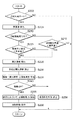
図2に、本発明の走行制御装置による走行制御のフローチャートを示す。図2に示されるフローチャートの制御は、所定時間毎に繰り返し実行されている。まず、モード設定スイッチ8が運転者(乗員)によってオンにされて自動制動モードに移行しているか否かが判定される(ステップ200)。自動制動モードとなっていればクリープ走行時の自動制動が行われ得るが、自動制動モードになっていなければクリープ走行時の自動制動は行われずに通常のクリープ走行となる。
【0016】
なお、ここで、モード設定スイッチ8がオンにされて自動制動モードとなっている場合は、クリープトルクが自動制動モードでないときよりも大きく設定される。自動制動モードにあれば後述する自動制動が行われるので、自動制動モード中のクリープトルクを大きくすることで、急加速を抑止しつつ車両の良好な加速性を実現することが可能となる。
【0017】
なお、クリープトルクを大きくするには、エンジンECU9によってアイドル回転数を増加させればよい。アイドル回転数の増加は、スロットルバルブ12によってアイドル時の吸入空気量を増やすことで行える。あるいは、点火プラグ10の点火時期を制御したり、インジェクタ11から噴射される燃料噴射量を制御してクリープトルクを増大させることも可能である。これらを併用してもよい。
ステップ200が否定される場合は、クリープ走行時の自動制動は行われることはなく、図2に示されるフローチャートはそのまま抜け、クリープ走行は通常のクリープ走行となる。
【0018】
一方、ステップ200が肯定される場合は、車両の実車速を検出する(ステップ205)。実車速は、車輪速センサ3の出力パルスに基づいてブレーキECU1において演算されることで検出される。次に、クリープ走行中の自動制動が既に実行されている状態(制動中)であるか否かが判定される(ステップ210)。自動制動モードが設定されているがまだ自動制動が行われておらず制動中ではない場合、即ち、ステップ210が否定される場合は、次に、ステップ205で検出した実車速が制御開始車速よりも大きいか否かを判定する(ステップ215)。
【0019】
ステップ215が否定される場合、即ち、実車速が制御開始車速以下である場合は、車速が十分に低速であるので自動制動制御を開始する必要はないとしてそのまま図2のフローチャートを抜ける。これに対して、ステップ215が肯定される場合、即ち、実車速が制御開始車速よりも大きいときは、自動制動制御が開始され、まず、自動制動を行うか否かを判定するために車両の前後方向に作用する実加速度を検出する(ステップ225)。なお、自動制動制御の開始が、実際の自動制動の開始を意味するのではなく、自動制動制御開始後に自動制動を行うか否かを判定し(後述するステップ225〜255参照)、行うと判定された場合に実際の自動制動が実行されることになる。
【0020】
一方、ステップ210が肯定される場合、即ち、既にクリープ走行中の自動制動が実行されている場合(制動中)は、ステップ205で検出した実車速が制御終了車速よりも大きいか否かを判定する(ステップ220)。ステップ220が否定される場合、即ち、実車速が制御終了車速以下である場合は、車速が十分に低速であるので自動制動を続行する必要はないとして自動制動制御を停止させる(ステップ250)。このとき、自動制動制御の終了と共に実際の自動制動も終了する。ステップ250の後、図2のフローチャートを抜ける。これに対して、ステップ220が肯定される場合、即ち、実車速が制御終了車速よりも大きいときは、自動制動を続行すべく、新たに車両の前後方向に作用する実加速度を検出する(ステップ225)。
【0021】
なお、制御終了車速<制御開始車速とされており、このように制御開始車速と終了車速とにヒステリシスを設けることで、制御開始と終了とが繰り返されるハンチングを防止できる。ステップ215が肯定され、あるいは、ステップ220が肯定されてステップ225で実加速度が検出された後、上限加速度を算出する(ステップ230)。クリープ走行時に車両の前後方向に作用する実加速度がこの上限加速度以上となると、自動制動が実行される。なお、本実施形態では、上限加速度は車速に応じて設定される。車両が極低速であれば、比較的小さな減速度(負の加速度)が作用するだけでも減速感を強く感じて操作しにくいと感じてしまう。しかし、やや速度が上昇すれば同じ減速度(負の加速度)でも減速感は和らぎ、操作のしにくさは感じにくくなる。即ち、車速に応じて上限加速度を設定した方が、車両をより操作しやすくすることができる。
【0022】
ステップ230の後、偏差=(実加速度)−(上限加速度)を算出する(ステップ235)。さらに、算出した偏差が0以上であるか否かを判定する(ステップ240)。偏差が0未満の場合は、実加速度が上限加速度に達していないので、継続されている自動制動制御を(同時に実際の自動制動も)終了して(ステップ250)、図2に示されるフローチャートを抜ける。一方、偏差が0以上である場合は、実加速度が上限加速度以上となっているので、実際に自動制動を行うべく偏差に基づいて必要な制動力を算出し(ステップ255)、算出された必要制動力が得られるように自動制動を実行する(ステップ260)。
【0023】
なお、ここでは偏差に基づいて必要な制動力を算出するが、この「必要な制動力」は偏差を0にするような制動力でも良いし、偏差を負とするような制動力でも良い。また、本実施形態では、偏差に基づいて制動力を決定することとしたが、偏差によらずに所定の制動力を発生させるようにすることも可能である。例えば、実加速度が上限加速度を超えたら、その時点での車速に応じて所定の制動力を発生させ、加速度が負(減速)になるまで予め定められた所定の割合で制動力を増やすような制御も可能である。
【0024】
ステップ255,260では、オイルポンプ4によって発生させる油圧やバルブ5の開閉デューティー比などを制御することによって制動力を調節する。このように、検出した実加速度と設定した上限加速度とに基づいて、クリープ走行時に自動制動を行うようにすることで、クリープ走行時の車両の運転をより行いやすくすることが可能となる。具体的には、車速の上昇が緩慢になることも抑止できる一方で、急加速などを防止することができる。また、運転者に運転させる余地を残しているので、運転者が運転に気を配らなくなってしまうような状況を回避することもできる。
【0025】
なお、本発明は上述した実施形態に限定されるものではない。例えば、車両がハイブリッド車である場合などは、車両を制動させる自動制動手段として、回生発電する電気モータを利用しても良い。また、上述した実施形態では、クリープ走行時に実加速度と設定された上限加速度とに基づいて自動制動を行う走行制御装置に対して、モード設定手段及びトルク上昇手段を備えることと、車速に応じて上限加速度を設定することとを併用した。しかし、モード設定手段及びトルク上昇手段を備えることと、車速に応じて上限加速度を設定することとを併用しなくても構わないし、モード設定手段とトルク上昇手段のいずれか一方のみと、車速に応じた上限加速度の設定とを併用するようにしても良い。
【0026】
また、上述した実施形態では、車速に応じて上限加速度を設定したが、上限加速度設定手段が車速にかかわらず一定の上限加速度を設定するようであっても良い。さらに、上述したように、本発明における「クリープ走行」にはハイブリッド車や電気自動車などでモータによって実現するクリープ走行も含む。この場合のトルク上昇手段は、モータの発生トルクを上昇させる手段であり、具体的には、モータへの供給電力を上昇させる機構(ECUやインバータなど)によって実現される。
【0027】
【発明の効果】
本発明の車両走行制御装置によれば、検出した実加速度と設定した上限加速度とに基づいて、クリープ走行時に自動制動を行うようにすることで、クリープ走行時の車両の運転をより行いやすくすることができる。ここで、自動制動モードを設定して、このモード中のクリープトルクを上昇させれば、クリープ走行時の車両の運転をさらに向上させることができる。また、車速に応じて上限加速度を設定するようにしても、クリープ走行時の車両の運転をさらに向上させることができる。
【図面の簡単な説明】
【図1】本発明の車両走行制御装置の一実施形態を示す構成図である。
【図2】本発明の車両走行制御装置の一実施形態による車両自動制動制御のフローチャートである。
【符号の説明】
1…ブレーキECU、2…加速度センサ、3…車輪速センサ、4…オイルポンプ、5…バルブ、6…リザーバタンク、7…ホイールシリンダ、8…モード設定スイッチ、9…エンジンECU、10…点火プラグ、11…インジェクタ、12…スロットルバルブ。[0001]
TECHNICAL FIELD OF THE INVENTION
The present invention relates to a vehicle traveling control device that controls vehicle traveling during creep traveling.
[0002]
[Prior art]
In an automatic transmission vehicle (AT vehicle) using a torque converter (fluid coupling), even when the accelerator pedal is not depressed, the engine output due to idle rotation can be transmitted to the wheels, so that the vehicle can run. This is so-called creep running. If the automatic transmission's select lever position is in the D range or the R range, creep travel can be performed at low speed simply by loosening the foot brake, which is convenient during traffic jams and garages.
[0003]
If the vehicle speed during creep running is too low, it takes too much time to move the vehicle, which is inconvenient. Conversely, if the vehicle speed during creep running is too high, the driver must frequently perform the brake operation, which is also inconvenient. In the automatic steering system using creep running described in Japanese Patent Application Laid-Open No. 10-297520, the driver is required to brake the vehicle so that the vehicle speed falls within a predetermined range (creep vehicle speed suitable for performing automatic parking control). To evoke operation.
[0004]
[Problems to be solved by the invention]
However, in the case of the device described in the above-mentioned publication, although the automatic parking is performed within the appropriate vehicle speed, if the creep torque is low, the time required to reach the appropriate vehicle speed becomes longer, or the acceleration is deteriorated, and the usability is reduced. Is bad. On the other hand, if the creep torque is high, the acceleration performance is improved, but if the braking operation is delayed even a little, the vehicle speed rapidly increases even within an appropriate vehicle speed (sudden acceleration), so that the usability is poor. Therefore, there has been a demand for an improvement as a vehicle control device not only at the time of automatic parking but also at the time of creep running so as to make driving easier.
[0005]
Therefore, an object of the present invention is to provide a vehicle traveling control device that can further facilitate driving during creep traveling.
[0006]
[Means for Solving the Problems]
A vehicle travel control device according to claim 1, which controls a travel state of the vehicle during creep travel, detects actual acceleration acting in the longitudinal direction of the vehicle, and a longitudinal direction of the vehicle during creep travel. Upper limit acceleration setting means for setting an upper limit of the acceleration acting on the vehicle, and automatic braking means for braking the vehicle based on the actual acceleration detected by the actual acceleration detection means and the upper limit acceleration set by the upper limit acceleration setting means. It is characterized by:
[0007]
Some hybrid vehicles and electric vehicles use a motor to generate a vehicle driving torque corresponding to the creep torque of an AT vehicle having a torque converter, and realize creep running using the vehicle driving torque. The “creep running” in the present invention includes creep running realized by a motor in a hybrid vehicle, an electric vehicle, or the like.
[0008]
According to a second aspect of the present invention, there is provided the vehicle travel control device according to the first aspect, wherein the mode control means sets an automatic braking mode that enables automatic braking by the automatic braking means during creep traveling. When the automatic braking mode is set, a torque increasing means for increasing the creep torque as compared with when the automatic braking mode is not set is further provided.
[0009]
According to a third aspect of the present invention, in the vehicle traveling control device according to the first or second aspect, the upper limit acceleration setting means sets the upper limit acceleration according to the vehicle speed of the vehicle.
[0010]
BEST MODE FOR CARRYING OUT THE INVENTION
An embodiment of the present invention will be described below. FIG. 1 shows the configuration of the vehicle control device of the present invention. An acceleration sensor 2 for detecting the longitudinal acceleration of the vehicle and a wheel speed sensor 3 attached to each wheel and detecting the rotational speed of each wheel are connected to a brake ECU 1 for controlling the overall braking control of the vehicle. . The brake ECU 1 is also connected to an oil pump 4 that sends brake oil inside the reservoir tank 6 to a wheel cylinder 7 of each wheel via a valve 5. The valve 5 is also connected to the brake ECU 1, and its opening and closing are duty-controlled by the brake ECU 1.
[0011]
The valve 5 sends the brake oil from the oil pump 4 to the wheel cylinder 7 to increase (increase) the oil pressure inside the wheel cylinder 7 and perform braking of each wheel, and the brake oil inside the wheel cylinder 7 Can be returned to the reservoir tank 6 to reduce (reduce) the oil pressure inside the wheel cylinder 7. This hydraulic brake mechanism is also used during ABS control and brake assist control. Further, in the present embodiment, a
[0012]
The brake ECU 1 is responsible for not only braking control during creep running, which will be described later, but also ABS control and brake assist control. In addition, it also controls vehicle behavior stabilization control in cooperation with another ECU (such as an engine ECU 9 described later). An engine ECU 9 connected to the brake ECU 1 controls the overall control of the engine. Connected to the engine ECU 9 are an
[0013]
Here, the acceleration sensor 2 functions as actual acceleration detecting means, and the brake ECU 1 functions as upper limit acceleration setting means. Further, the brake ECU 1, the oil pump 4, the valve 5, the reservoir tank 6, the wheel cylinder 7, and the like function as automatic braking means. Further, the mode setting switch 8 functions as mode setting means. Further, the engine ECU 9 and the accompanying
[0014]
Next, traveling control during creep traveling by the traveling control device having the above-described configuration will be described. The creep running control of the present invention is to perform a creep running, for example, at the time of low-speed running in traffic congestion and when putting in a garage at the time of parking, it is possible to quickly move the vehicle and prevent sudden acceleration. The purpose is. Another purpose is to allow the driver to continue maneuvering while performing creep running control. For example, if the vehicle completely controls the vehicle speed and steering, there is a concern that the driver will not pay attention to driving. However, here, by setting an upper limit on the acceleration of the vehicle, it is possible to ensure that the creep running is safe and easy to operate, and that the driving is reliably performed while intentionally leaving room for the driver to drive.
[0015]
FIG. 2 shows a flowchart of traveling control by the traveling control device of the present invention. The control of the flowchart shown in FIG. 2 is repeatedly executed at predetermined time intervals. First, it is determined whether or not the
[0016]
Here, when the
[0017]
To increase the creep torque, the
If
[0018]
On the other hand, when
[0019]
If step 215 is denied, that is, if the actual vehicle speed is equal to or lower than the control start vehicle speed, the vehicle speed is sufficiently low, and it is determined that there is no need to start automatic braking control, and the process directly exits the flowchart in FIG. On the other hand, if step 215 is affirmative, that is, if the actual vehicle speed is higher than the control start vehicle speed, the automatic braking control is started, and first, the vehicle is controlled to determine whether to perform automatic braking. An actual acceleration acting in the front-rear direction is detected (step 225). The start of the automatic braking control does not mean the start of the actual automatic braking, but it is determined whether or not to perform the automatic braking after the start of the automatic braking control (see Steps 225 to 255 described later). In this case, the actual automatic braking is performed.
[0020]
On the other hand, if
[0021]
It should be noted that the control end vehicle speed is smaller than the control start vehicle speed. By providing hysteresis between the control start vehicle speed and the end vehicle speed in this way, hunting in which control start and end are repeated can be prevented. After step 215 is affirmed or step 220 is affirmed and the actual acceleration is detected at step 225, the upper limit acceleration is calculated (step 230). When the actual acceleration acting in the front-rear direction of the vehicle during creep running is equal to or higher than the upper limit acceleration, automatic braking is performed. In the present embodiment, the upper limit acceleration is set according to the vehicle speed. If the vehicle is at a very low speed, even if only a relatively small deceleration (negative acceleration) acts, the driver feels a strong sense of deceleration and feels it difficult to operate. However, if the speed is slightly increased, the feeling of deceleration is alleviated even with the same deceleration (negative acceleration), and the difficulty of operation becomes less perceptible. That is, setting the upper limit acceleration according to the vehicle speed can make the vehicle easier to operate.
[0022]
After
[0023]
Here, the required braking force is calculated based on the deviation, but the “necessary braking force” may be a braking force that makes the deviation zero or a braking force that makes the deviation negative. Further, in the present embodiment, the braking force is determined based on the deviation, but a predetermined braking force may be generated without depending on the deviation. For example, when the actual acceleration exceeds the upper limit acceleration, a predetermined braking force is generated according to the vehicle speed at that time, and the braking force is increased at a predetermined ratio until the acceleration becomes negative (deceleration). Control is also possible.
[0024]
In
[0025]
Note that the present invention is not limited to the embodiment described above. For example, when the vehicle is a hybrid vehicle, an electric motor for regenerative power generation may be used as automatic braking means for braking the vehicle. Further, in the above-described embodiment, the travel control device that performs automatic braking based on the actual acceleration and the set upper limit acceleration during the creep traveling includes the mode setting unit and the torque increasing unit, and according to the vehicle speed. Setting of the upper limit acceleration was also used. However, the provision of the mode setting means and the torque increasing means and the setting of the upper limit acceleration according to the vehicle speed may not be used in combination, and only one of the mode setting means and the torque increasing means and the vehicle speed The setting of the corresponding upper limit acceleration may be used together.
[0026]
In the above-described embodiment, the upper limit acceleration is set according to the vehicle speed. However, the upper limit acceleration setting means may set a constant upper limit acceleration regardless of the vehicle speed. Further, as described above, “creep running” in the present invention includes creep running realized by a motor in a hybrid vehicle, an electric vehicle, or the like. The torque increasing unit in this case is a unit that increases the generated torque of the motor, and is specifically realized by a mechanism (such as an ECU or an inverter) that increases the power supplied to the motor.
[0027]
【The invention's effect】
According to the vehicle traveling control device of the present invention, the vehicle is more easily driven during creep traveling by performing automatic braking during creep traveling based on the detected actual acceleration and the set upper limit acceleration. be able to. Here, by setting the automatic braking mode and increasing the creep torque during this mode, the driving of the vehicle during creep running can be further improved. Further, even if the upper limit acceleration is set according to the vehicle speed, the driving of the vehicle during creep running can be further improved.
[Brief description of the drawings]
FIG. 1 is a configuration diagram showing one embodiment of a vehicle traveling control device of the present invention.
FIG. 2 is a flowchart of a vehicle automatic braking control according to an embodiment of the vehicle traveling control device of the present invention.
[Explanation of symbols]
DESCRIPTION OF SYMBOLS 1 ... Brake ECU, 2 ... Acceleration sensor, 3 ... Wheel speed sensor, 4 ... Oil pump, 5 ... Valve, 6 ... Reservoir tank, 7 ... Wheel cylinder, 8 ... Mode setting switch, 9 ... Engine ECU, 10 ... Spark plug , 11 ... injector, 12 ... throttle valve.
Claims (3)
車両の前後方向に働く実加速度を検出する実加速度検出手段と、
クリープ走行時に車両の前後方向に働く加速度の上限を設定する上限加速度設定手段と、
前記実加速度検出手段によって検出された実加速度及び前記上限加速度設定手段によって設定された上限加速度に基づいて車両を制動させる自動制動手段とを備えていることを特徴とする車両走行制御装置。In a vehicle traveling control device that controls the traveling state of the vehicle during creep traveling,
An actual acceleration detecting means for detecting an actual acceleration acting in the longitudinal direction of the vehicle,
Upper limit acceleration setting means for setting an upper limit of acceleration acting in the longitudinal direction of the vehicle during creep running;
An automatic braking unit for braking the vehicle based on the actual acceleration detected by the actual acceleration detecting unit and the upper limit acceleration set by the upper limit acceleration setting unit.
前記モード制御手段によって自動制動モードが設定されたときには、非設定時よりもクリープトルクを上昇させるトルク上昇手段とをさらに備えていることを特徴とする請求項1に記載の車両走行制御装置。Mode setting means for setting an automatic braking mode that enables automatic braking by the automatic braking means during creep running,
2. The vehicle travel control device according to claim 1, further comprising: a torque increasing unit that increases a creep torque when the automatic braking mode is set by the mode control unit than when the automatic braking mode is not set. 3.
Priority Applications (3)
| Application Number | Priority Date | Filing Date | Title |
|---|---|---|---|
| JP2002177663A JP4242115B2 (en) | 2002-06-18 | 2002-06-18 | Vehicle travel control device |
| DE60331278T DE60331278D1 (en) | 2002-06-18 | 2003-06-17 | Automatic braking during the creep mode of a vehicle |
| EP03013733A EP1375278B8 (en) | 2002-06-18 | 2003-06-17 | Automatic braking during vehicle creep control |
Applications Claiming Priority (1)
| Application Number | Priority Date | Filing Date | Title |
|---|---|---|---|
| JP2002177663A JP4242115B2 (en) | 2002-06-18 | 2002-06-18 | Vehicle travel control device |
Publications (2)
| Publication Number | Publication Date |
|---|---|
| JP2004017865A true JP2004017865A (en) | 2004-01-22 |
| JP4242115B2 JP4242115B2 (en) | 2009-03-18 |
Family
ID=29717474
Family Applications (1)
| Application Number | Title | Priority Date | Filing Date |
|---|---|---|---|
| JP2002177663A Expired - Fee Related JP4242115B2 (en) | 2002-06-18 | 2002-06-18 | Vehicle travel control device |
Country Status (3)
| Country | Link |
|---|---|
| EP (1) | EP1375278B8 (en) |
| JP (1) | JP4242115B2 (en) |
| DE (1) | DE60331278D1 (en) |
Cited By (4)
| Publication number | Priority date | Publication date | Assignee | Title |
|---|---|---|---|---|
| JP2007032424A (en) * | 2005-07-27 | 2007-02-08 | Advics:Kk | Vehicle traveling control device |
| JP2009126352A (en) * | 2007-11-22 | 2009-06-11 | Aisin Seiki Co Ltd | Traveling control device for vehicle |
| US8150593B2 (en) | 2006-12-08 | 2012-04-03 | Toyota Jidosha Kabushiki Kaisha | Vehicle control apparatus, and vehicle control method |
| JP2019172088A (en) * | 2018-03-28 | 2019-10-10 | 本田技研工業株式会社 | Automatic parking device |
Families Citing this family (4)
| Publication number | Priority date | Publication date | Assignee | Title |
|---|---|---|---|---|
| SE530053E (en) * | 2006-05-26 | 2009-10-28 | Scania Cv Abp | System and method for controlling a slow-motion operation intended for motor vehicles |
| GB2483720B (en) * | 2010-09-20 | 2017-10-25 | Jaguar Land Rover Ltd | Improvements relating to brake control |
| US11027733B2 (en) | 2015-06-17 | 2021-06-08 | Volvo Truck Corporation | Vehicle speed control system |
| DE102017221986A1 (en) * | 2017-12-06 | 2019-06-06 | Zf Friedrichshafen Ag | Method and control device for operating an electric vehicle or a hybrid vehicle |
Family Cites Families (7)
| Publication number | Priority date | Publication date | Assignee | Title |
|---|---|---|---|---|
| KR930004579B1 (en) * | 1988-11-09 | 1993-06-01 | 미쯔비시 덴끼 가부시기가이샤 | Slow speed cruising control apparatus |
| GB9420561D0 (en) * | 1994-10-12 | 1994-11-30 | Rover Group | A wheeled vehicle |
| JP3588868B2 (en) * | 1995-08-04 | 2004-11-17 | 日産自動車株式会社 | Driving force control device for vehicles |
| JP3182509B2 (en) * | 1997-04-28 | 2001-07-03 | 本田技研工業株式会社 | Automatic steering system for vehicles with automatic transmission |
| DE19753764A1 (en) * | 1997-12-04 | 1999-06-10 | Itt Mfg Enterprises Inc | Method and device for maneuvering motor vehicles |
| GB9819519D0 (en) * | 1998-09-09 | 1998-10-28 | Rover Group | Vehicle brake control |
| DE29818131U1 (en) | 1998-10-10 | 1999-01-14 | Brandstaetter Geobra | Caterpillar belt for toy vehicles |
-
2002
- 2002-06-18 JP JP2002177663A patent/JP4242115B2/en not_active Expired - Fee Related
-
2003
- 2003-06-17 DE DE60331278T patent/DE60331278D1/en not_active Expired - Lifetime
- 2003-06-17 EP EP03013733A patent/EP1375278B8/en not_active Expired - Lifetime
Cited By (5)
| Publication number | Priority date | Publication date | Assignee | Title |
|---|---|---|---|---|
| JP2007032424A (en) * | 2005-07-27 | 2007-02-08 | Advics:Kk | Vehicle traveling control device |
| JP4618035B2 (en) * | 2005-07-27 | 2011-01-26 | 株式会社アドヴィックス | Vehicle travel control device |
| US8150593B2 (en) | 2006-12-08 | 2012-04-03 | Toyota Jidosha Kabushiki Kaisha | Vehicle control apparatus, and vehicle control method |
| JP2009126352A (en) * | 2007-11-22 | 2009-06-11 | Aisin Seiki Co Ltd | Traveling control device for vehicle |
| JP2019172088A (en) * | 2018-03-28 | 2019-10-10 | 本田技研工業株式会社 | Automatic parking device |
Also Published As
| Publication number | Publication date |
|---|---|
| EP1375278B8 (en) | 2010-11-17 |
| DE60331278D1 (en) | 2010-04-01 |
| EP1375278A3 (en) | 2007-01-17 |
| JP4242115B2 (en) | 2009-03-18 |
| EP1375278A2 (en) | 2004-01-02 |
| EP1375278B1 (en) | 2010-02-17 |
Similar Documents
| Publication | Publication Date | Title |
|---|---|---|
| JP3675281B2 (en) | Automatic engine stop / restart device for vehicle | |
| JP3885449B2 (en) | Automatic engine stop / restart device for vehicle | |
| US7877184B2 (en) | Control apparatus and control method for hybrid vehicle | |
| JP3715158B2 (en) | Engine stop / start control device | |
| US8606441B2 (en) | Vehicular control device, method of controlling a vehicle, and a storage medium having stored therein a program that implements the method | |
| JP2007055536A (en) | Automobile and control method therefor | |
| JP3588673B2 (en) | Idle stop vehicle | |
| JP2004225576A (en) | Automatic stop and start control device for engine | |
| JP2004320850A (en) | Motor torque controller for vehicle | |
| JP4172185B2 (en) | Vehicle operation control device | |
| JP4207996B2 (en) | Hybrid car | |
| JP2006152965A (en) | Vehicle, control device for vehicular engine and engine control method | |
| JP3343679B2 (en) | Control device for vehicle power transmission | |
| JP4242115B2 (en) | Vehicle travel control device | |
| JP3852250B2 (en) | Control device for front and rear wheel drive vehicle | |
| JP2015090141A (en) | Vehicle | |
| JP2006194263A (en) | Automobile and method for controlling the same | |
| JP3572868B2 (en) | Vehicle control device | |
| JP3721830B2 (en) | Control device for hybrid vehicle | |
| JP2004162624A (en) | Engine automatic stop device of vehicle | |
| JP3589814B2 (en) | Power steering device | |
| JP3923451B2 (en) | Control device for hybrid vehicle | |
| JP3707258B2 (en) | Control device for front and rear wheel drive vehicle | |
| JP2007245779A (en) | Method for controlling amount of assist torque | |
| JP3875097B2 (en) | Driving control device for hybrid vehicle |
Legal Events
| Date | Code | Title | Description |
|---|---|---|---|
| A977 | Report on retrieval |
Free format text: JAPANESE INTERMEDIATE CODE: A971007 Effective date: 20060324 |
|
| A131 | Notification of reasons for refusal |
Free format text: JAPANESE INTERMEDIATE CODE: A131 Effective date: 20060328 |
|
| A521 | Written amendment |
Free format text: JAPANESE INTERMEDIATE CODE: A523 Effective date: 20060529 |
|
| A131 | Notification of reasons for refusal |
Free format text: JAPANESE INTERMEDIATE CODE: A131 Effective date: 20060912 |
|
| A521 | Written amendment |
Free format text: JAPANESE INTERMEDIATE CODE: A523 Effective date: 20061110 |
|
| A02 | Decision of refusal |
Free format text: JAPANESE INTERMEDIATE CODE: A02 Effective date: 20070710 |
|
| A521 | Written amendment |
Free format text: JAPANESE INTERMEDIATE CODE: A523 Effective date: 20070827 |
|
| A911 | Transfer to examiner for re-examination before appeal (zenchi) |
Free format text: JAPANESE INTERMEDIATE CODE: A911 Effective date: 20070914 |
|
| A912 | Re-examination (zenchi) completed and case transferred to appeal board |
Free format text: JAPANESE INTERMEDIATE CODE: A912 Effective date: 20071005 |
|
| A01 | Written decision to grant a patent or to grant a registration (utility model) |
Free format text: JAPANESE INTERMEDIATE CODE: A01 |
|
| A61 | First payment of annual fees (during grant procedure) |
Free format text: JAPANESE INTERMEDIATE CODE: A61 Effective date: 20081224 |
|
| FPAY | Renewal fee payment (event date is renewal date of database) |
Free format text: PAYMENT UNTIL: 20120109 Year of fee payment: 3 |
|
| FPAY | Renewal fee payment (event date is renewal date of database) |
Free format text: PAYMENT UNTIL: 20120109 Year of fee payment: 3 |
|
| FPAY | Renewal fee payment (event date is renewal date of database) |
Free format text: PAYMENT UNTIL: 20130109 Year of fee payment: 4 |
|
| FPAY | Renewal fee payment (event date is renewal date of database) |
Free format text: PAYMENT UNTIL: 20130109 Year of fee payment: 4 |
|
| LAPS | Cancellation because of no payment of annual fees |