JP2004017761A - Control device for on-vehicle apparatus - Google Patents
Control device for on-vehicle apparatus Download PDFInfo
- Publication number
- JP2004017761A JP2004017761A JP2002174486A JP2002174486A JP2004017761A JP 2004017761 A JP2004017761 A JP 2004017761A JP 2002174486 A JP2002174486 A JP 2002174486A JP 2002174486 A JP2002174486 A JP 2002174486A JP 2004017761 A JP2004017761 A JP 2004017761A
- Authority
- JP
- Japan
- Prior art keywords
- reaction force
- operation reaction
- unit
- pattern
- vehicle
- Prior art date
- Legal status (The legal status is an assumption and is not a legal conclusion. Google has not performed a legal analysis and makes no representation as to the accuracy of the status listed.)
- Pending
Links
Images


Landscapes
- Position Input By Displaying (AREA)
- Switch Cases, Indication, And Locking (AREA)
- Mechanical Control Devices (AREA)
Abstract
Description
【0001】
【発明の属する技術分野】
本発明は、操作反力が設定可能な操作部を有する車載機器操作装置に関する。
【0002】
【従来の技術】
従来から、車両に備わった各種の機器の操作部を共用化することにより、各種の機器の配置を容易にしたり、操作性を向上させようとする提案がなされている。例えば、特開2000−149721号公報には、オーディオ装置、ナビゲーション装置、エアコン、電話等の各種の車載機器の操作を共通の操作部を用いて行うことが可能な「車載機器用操作装置」が開示されている。この車載機器用操作装置には操作力調整用ソレノイドが用いられており、車載機器の種類や操作内容に応じて、操作部材に加わる操作反力を可変することができるようになっている。
【0003】
【発明が解決しようとする課題】
ところで、上述した公報に開示された車載機器用操作装置は、操作部材に加わる操作反力が車載機器の種類や操作内容に応じて設定されるが、一般にはその設定内容は平均的な利用者を想定して決められるため、個々の利用者によっては、操作反力が強すぎたり、あるいは弱すぎたりして操作に不快感を感じる場合があるという問題があった。特に、快適に感じる操作反力の大きさは利用者毎に異なっていると考えられるため、画一的に設定された操作反力に対しては、大多数の利用者が快適に感じる場合であっても、少数の利用者にとっては不快に感じることになる。
【0004】
また、車載機器の中には、運転中と停車中の両方において操作するものもあるが、一般に、停車中に操作する場合の操作反力の感じ方と、運転中に操作する場合の操作反力の感じ方とでは異なっていると考えられる。例えば、停車中の場合には、操作部材の操作に集中することができるため、比較的小さな操作反力であっても利用者に対して正確に伝わるが、運転中の場合には、小さな操作反力では利用者に対して伝わりにくくなる。したがって、車両の走行状態にかかわらず一定の操作反力を発生させた場合には、走行状態によっては利用者にとって操作反力が必要以上に大きく感じたり、反対に操作反力が極端に小さく感じたりする場合があり、操作部材の的確な位置決め等が困難になって操作性が悪いという問題があった。
【0005】
本発明は、このような点に鑑みて創作されたものであり、その目的は、適切な操作反力を発生させることにより、操作時の不快感をなくすとともに操作性を向上させることができる車載機器操作装置を提供することにある。
【0006】
【課題を解決するための手段】
上述した課題を解決するために、本発明の車載機器操作装置は、利用者によって操作される操作部と、変更可能な操作反力を操作部に加える操作反力発生手段と、利用者による指示に応じて、操作反力発生手段によって発生する操作反力の強弱を切り替える操作反力設定手段とを備えている。利用者の指示によって操作反力の強弱を切り替えることにより、利用者自身が心地よいと感じる適切な操作反力を実現することができるため、操作時の不快感をなくすることが可能になる。
【0007】
また、上述した操作反力設定手段は、車両の走行状態に応じて、操作反力の強弱を切り替えることが望ましい。車両の走行状態に応じて操作反力を切り替えることにより、停車中および走行中のそれぞれの状態において最適な操作反力を設定することができ、それぞれの状態における操作性の向上が可能になる。
【0008】
また、本発明の車載機器操作装置は、利用者によって操作される操作部と、変更可能な操作反力を操作部に加える操作反力発生手段と、車両の走行状態に応じて、操作反力発生手段によって発生する操作反力の強弱を切り替える操作反力設定手段とを備えている。上述したように、車両の走行状態に応じて操作反力を切り替えることにより、停車中および走行中のそれぞれの状態において最適な操作反力を設定することができ、それぞれの状態における操作性の向上が可能になる。
【0009】
また、複数の操作内容のそれぞれに対応した操作反力の発生パターンを格納する反力パターン格納手段をさらに備え、操作反力設定手段は、一の操作内容が選択されたときに、対応する発生パターンを反力パターン格納手段から読み出して、操作反力発生手段によって発生する操作反力を設定することが望ましい。これにより、複数の操作内容のそれぞれに対応したパターンの操作反力の発生が可能になるとともに、各パターンにおいて利用者毎あるいは走行状態に応じて操作反力を可変することにより、操作時の不快感をなくして操作性の向上を図ることが可能になる。
【0010】
【発明の実施の形態】
以下、本発明の車載機器操作装置を適用した一実施形態の車載システムについて、図面を参照しながら説明する。
図1は、本実施形態の車載システムの構成を示す図である。図1に示す車載システムは、操作ユニット100、表示ユニット200、ナビゲーション装置300、オーディオ装置310、ラジオ受信機320、エアコン330を含んで構成されている。操作ユニット100は、利用者が操作することにより、操作対象の車載機器としてのナビゲーション装置300、オーディオ装置310、ラジオ受信機320、エアコン330のそれぞれに対して各種の動作指示を与えるためのものである。本実施形態では、各種の車載機器に対応して一つの操作ユニット100が設けられており、各車載機器に異なる内容の動作指示が与えられる。また、表示ユニット200は、操作ユニット100による操作を行う際の操作画面やナビゲーション装置300の出力画像等を表示する。
【0011】
上述した操作ユニット100、表示ユニット200、ナビゲーション装置300、オーディオ装置310、ラジオ受信機320およびエアコン330のそれぞれは、車内バスを介して接続されており、相互に各種のデータが送受信される。操作ユニット100は、操作管理部10、個人データ格納部12、パターン切替部14、発生パターン格納部18、モータ出力計算部20、操作ノブ30、位置検出部34、モータ36を備えている。
【0012】
操作ノブ30は、レバー32を中心に回転可能に取り付けられた操作部であり、利用者によって回転駆動力が与えられると、そのときに発生している操作反力に対応した回転動作を行う。位置検出部34は、例えばレバー32に取り付けられており、操作ノブ30の位置(回転角)を検出する。モータ36は、レバー32を介して操作ノブ30に加わる操作反力を発生する。
【0013】
操作管理部10は、ナビゲーション装置300等から送られてくる情報に基づいて操作種別を設定するとともに、この設定された操作種別に対応した操作結果出力動作の制御を行う。例えば、代表的な操作種別として、「ボリューム操作」や「メニュー選択」等が設定される。本実施形態では、このようにして設定された操作種別に対応する操作反力を発生させることにより、各操作種別に適した操作ノブ30の操作感が実現されるが、実際に操作ノブ30を操作したときにこの操作状況に応じた出力値を作成して操作ユニット100から出力する必要があり、操作管理部10は、この出力値を作成する操作結果出力動作を行う。例えば、操作種別として「ボリューム操作」が設定された場合には、操作ノブ30が利用者の操作によって回転したときに、その回転角に対応したボリューム値が出力値として作成される。
【0014】
また、本実施形態では、操作反力の強弱の程度を各利用者毎に登録することができるようになっており、操作管理部10は、所定の登録画面を表示ユニット200に表示させて所定の登録作業を行う。
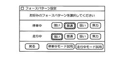
図2は、登録画面の表示例を示す図である。図2に示すように、登録画面には、停車中と走行中のそれぞれにおいて各利用者が好みの操作反力の強弱を選択する4種類の選択肢「強い」、「普通」、「弱い」、「無力」が用意されている。この登録画面を用いることにより、停車中と走行中のそれぞれに対応する操作反力の強弱を、その利用者のフォースパターンとして設定することができる。なお、登録画面には、「停車中モード試用」ボタンと「走行中モード試用」ボタンが含まれており、利用者は、いずれかのボタンを押下することにより、各走行状態に対応してその時点で選択されている操作反力を実際に発生させて確かめることができる。
【0015】
個人データ格納部12は、操作管理部10によって行われた登録作業によって設定された各利用者毎のフォースパターンを個人データとして格納する。例えば、図2に示した登録画面を用いて設定された停車中および走行中のそれぞれの操作反力の強弱の程度を示すデータが各利用者の識別IDとともに個人データ格納部12に格納される。
【0016】
パターン切替部14は、操作管理部10によって設定された操作種別に対応する操作反力の発生パターンを指定する。この指定は、選択した発生パターンに対応するパターン番号PNを出力することにより行われる。また、パターン切替部14は、外部から入力される車速信号に基づいて判定される車両の走行状態や、個人データ格納部12に格納されている各利用者毎の個人データとに基づいて、操作反力の強弱の程度を設定するゲインGを設定する。上述したように、停車中あるいは走行中のそれぞれにおける操作反力の強弱の程度が4種類の選択肢「強い」、「普通」、「弱い」、「無力」の中から選択されて各個人毎の個人データが作成されており、例えば、それぞれの選択肢に対応してゲインGが1.2、1.0、0.8、0にそれぞれ設定される。また、外部から入力される車速信号は、例えば、ナビゲーション装置300に用いられている車速センサの出力を用いたり、車両の速度計に入力される車速信号を用いることができる。
【0017】
発生パターン格納部18は、操作種別のそれぞれに対応した操作反力の発生パターンを特定するデータを格納する。
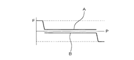
図3および図4は、操作種別のそれぞれに対応した操作反力の発生パターンを示す図である。例えば、図3には操作種別「ボリューム操作」に対応する操作反力の発生パターンが、図4には操作種別「メニュー選択」に対応する操作反力の発生パターンが示されている。これらの図において、横軸は操作ノブ30の回転方向の位置Pを、縦軸は所定の操作反力を発生させるために必要なモータ出力値Fをそれぞれ示している。モータ出力値に対応するようにモータ36によって操作反力が発生するように制御されるため、図3および図4に示した縦軸は操作反力そのものの発生パターンを示している。
【0018】
図3に示すように、操作種別「ボリューム操作」に対応する操作反力の発生パターンには、反時計回り方向に操作ノブ30を回転させたときに発生する操作反力の発生パターンAと、時計回り方向に操作ノブ30を回転させたときに発生する操作反力の発生パターンBとが含まれている。例えば、オーディオ装置310の音量等を大きくするために、操作ノブ30を時計回り方向に回転させる場合を考えると発生パターンBが選択される。このとき、この回転方向に沿って反対向きの弱い操作反力が発生するように制御され、ある位置まで操作ノブ30を回転させると、操作ノブ30が突き当たる操作感を出すために、急に操作反力が大きくなる。
【0019】
また、図4に示すように、操作種別「メニュー選択」に対応する操作反力の発生パターンには、メニュー画面に含まれる複数の選択肢に対応する複数の領域(図4では2カ所の領域)C、Dが含まれている。操作ノブ30を回転させたときに、その位置が領域Cから領域Dに移ったときに、メニュー画面内の選択状態が一方の選択肢から他方の選択肢に移動する。したがって、各選択肢内で操作ノブ30を動かしている間は、向きが周期的に変動する微少な操作反力が発生して操作ノブ30を操作していることを利用者に認識させることが可能になる。また、選択肢が切り替わる位置(領域Cと領域Dの中間位置)では、障害物を乗り越えたような大きな操作反力が操作ノブ30に作用するため、選択肢が切り替わったことを利用者に認識させることが可能になる。
【0020】
モータ出力計算部20は、位置検出部34によって検出される操作ノブ30の位置に対応するモータ出力値をモータ36に向けて出力することにより、モータ36によって発生する操作反力を制御する。具体的には、モータ出力計算部20は、パターン切替部14によって指定されたパターン番号PNによって特定される操作反力の発生パターンデータを発生パターン格納部18から読み出し、この発生パターンに基づいて操作ノブ30の位置に対応するモータ出力値を求め、さらにこの値にパターン切替部14によって設定されたゲインGを乗算して最終的なモータ出力値を計算する。
【0021】
上述した操作ノブ30が操作部に、モータ36が操作反力発生手段に、操作管理部10、パターン切替部14、モータ出力計算部20が操作反力設定手段に、発生パターン格納部18が反力パターン格納手段にそれぞれ対応する。
本実施形態の操作ユニット100はこのような構成を有しており、次にパターン切替部14とモータ出力計算部20の詳細な動作を説明する。
【0022】
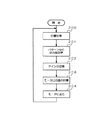
図5は、パターン切替部14の動作手順を示す流れ図である。まず、パターン切替部14は、操作種別が変更されたか否かを判定する(ステップ100)。ナビゲーション装置300等の各車載機器によって操作種別が操作管理部10に通知されるものとすると、いずれかの車載機器から新しい操作種別が通知された場合にはステップ100の判定で肯定判断が行われる。次に、パターン切替部14は、操作管理部10から新しい操作種別のデータを取得し(ステップ101)、この取得した操作種別に対応する操作反力の発生パターンを特定するために必要なパターン番号を出力する(ステップ102)。
【0023】
このようにしてパターン番号が出力された後、あるいは、操作種別が変更されずにステップ100において否定判断が行われた後に、パターン切替部14は、車速が変化したか否かを判定する(ステップ103)。この判定は外部から入力される車速信号に基づいて行われる。車速が変化した場合にはステップ103の判定において肯定判断が行われ、次に、パターン切替部14は、個人データ格納部12から現在の利用者に対応する個人データを取得する(ステップ104)。また、パターン切替部14は、その時点における車速が所定値(例えば時速4km)以上か否かを判定する(ステップ105)。車速が所定値よりも遅い場合には否定判断が行われ、パターン切替部14は、停車中に対応する操作反力の強弱の程度に応じたゲインGを出力する(ステップ106)。一方、車速が所定値以上の場合には肯定判断が行われ、パターン切替部14は、走行中に対応する操作反力の強弱の程度に応じたゲインGを出力する(ステップ107)。
【0024】
このようにしてゲインGが出力された後、あるいは車速が変化しない場合にはステップ103において否定判断が行われた後、ステップ100に戻って処理が繰り返される。
図6は、モータ出力計算部20の動作手順を示す流れ図である。モータ出力計算部20は、位置検出部34の出力に基づいて操作ノブ30の位置を検出すると(ステップ200)、その時点で選択されている操作反力の発生パターンに基づいて、この検出位置に対応するモータ出力値を取得する(ステップ201)。また、モータ出力計算部20は、パターン切替部14から出力されたゲインGを取得し(ステップ202)、ステップ201で取得したモータ出力値にこのゲインGを乗算して実際のモータ出力値を計算する(ステップ203)。次に、モータ出力計算部20は、この計算したモータ出力値に対応する電圧(あるいは電流)をモータ36に向けて出力する(ステップ204)。このようにして、モータ36によって発生する操作反力が制御される。その後、ステップ200に戻って処理が繰り返される。
【0025】
このように、本実施形態の操作ユニット100では、利用者毎の設定操作によって操作反力の強弱を切り替えることにより、利用者自身が心地よいと感じる適切な操作反力を実現することができるため、操作時の不快感をなくすることが可能になる。また、車両の走行状態に応じて操作反力を切り替えることにより、停車中および走行中のそれぞれの状態において最適な操作反力を設定することができ、それぞれの状態における操作性の向上が可能になる。
【0026】
なお、本発明は上記実施形態に限定されるものではなく、本発明の要旨の範囲内において種々の変形実施が可能である。例えば、上述した実施形態では、操作ノブ30を回転させるタイプの操作ユニット100について説明したが、操作ノブを二次元平面内で移動させるタイプの操作ユニットにも本発明を適用することができる。この場合には、二次元平面のX方向およびY方向のそれぞれに沿って操作反力を発生させる2つのモータ(あるいはソレノイド等の他の駆動手段)を備えておいて、これらの各モータへ出力するモータ出力値を制御すればよい。
【0027】
また、上述した本実施形態では、複数の車載機器に対応して共通に設けられた操作ユニット100において、各種の操作種別に対応した操作反力を発生させるようにしたが、一つの車載機器に対応して操作反力の発生パターンが固定化されている場合にも本発明を適用することができる。例えば、オーディオ装置の音量設定用の操作部について、車両の走行状態や各利用者毎の個人データの内容に応じて操作反力の強弱を切り替えるようにしてもよい。
【0028】
また、上述した実施形態では、車両の走行状態(停車中か走行中か)と各利用者毎の設定内容にしたがって操作反力の強弱を切り替えるようにしたが、その他の条件を用いて操作反力の強弱を切り替えるようにしてもよい。例えば、走行状態として、走行道路が一般道路か高速道路か、走行時間が夜間かそれ以外か、等を判定して操作反力の強弱を切り替えたり、利用者の性別や年齢によって操作反力の強弱を切り替えるようにしてもよい。
【0029】
【発明の効果】
上述したように、本発明によれば、利用者の指示によって操作反力の強弱を切り替えることにより、利用者自身が心地よいと感じる適切な操作反力を実現することができるため、操作時の不快感をなくすることが可能になる。また、車両の走行状態に応じて操作反力を切り替えることにより、停車中および走行中のそれぞれの状態において最適な操作反力を設定することができ、それぞれの状態における操作性の向上が可能になる。
【図面の簡単な説明】
【図1】一実施形態の車載システムの構成を示す図である。
【図2】登録画面の表示例を示す図である。
【図3】操作種別のそれぞれに対応した操作反力の発生パターンを示す図である。
【図4】操作種別のそれぞれに対応した操作反力の発生パターンを示す図である。
【図5】パターン切替部の動作手順を示す流れ図である。
【図6】モータ出力計算部の動作手順を示す流れ図である。
【符号の説明】
10 操作管理部
12 個人データ格納部
14 パターン切替部
18 発生パターン格納部
20 モータ出力計算部
30 操作ノブ
32 レバー
34 位置検出部
36 モータ
100 操作ユニット
200 表示ユニット
300 ナビゲーション装置
310 オーディオ装置
320 ラジオ受信機
330 エアコン[0001]
TECHNICAL FIELD OF THE INVENTION
The present invention relates to an in-vehicle device operation device having an operation unit capable of setting an operation reaction force.
[0002]
[Prior art]
2. Description of the Related Art Conventionally, proposals have been made to simplify the arrangement of various devices and improve operability by sharing operation units of various devices provided in a vehicle. For example, Japanese Patent Application Laid-Open No. 2000-149721 discloses an "operating device for an in-vehicle device" that can operate various in-vehicle devices such as an audio device, a navigation device, an air conditioner, and a telephone using a common operating unit. It has been disclosed. The operating device for an in-vehicle device uses an operating force adjusting solenoid, and the operation reaction force applied to the operating member can be varied according to the type and operation content of the in-vehicle device.
[0003]
[Problems to be solved by the invention]
By the way, in the operating device for an in-vehicle device disclosed in the above-mentioned publication, the operation reaction force applied to the operating member is set according to the type and the operation content of the in-vehicle device. Therefore, there is a problem that the operation reaction force may be too strong or too weak to make the operation uncomfortable depending on the individual user. In particular, since the magnitude of the operation reaction force that feels comfortable is considered to differ from user to user, the operation reaction force that is set uniformly is not suitable for the case where the majority of users feel comfortable. Even so, it will be uncomfortable for a small number of users.
[0004]
Some on-vehicle devices operate both while driving and when stopped, but in general, how to feel the reaction force when operating while stopped, and how to operate when operating while driving. It is considered different from the way of feeling power. For example, when the vehicle is stopped, it is possible to concentrate on the operation of the operation member, so that even a relatively small operation reaction force can be accurately transmitted to the user, but when the vehicle is driving, a small operation The reaction force makes it difficult to transmit to the user. Therefore, when a certain operation reaction force is generated regardless of the running state of the vehicle, the operation reaction force is felt by the user to be unnecessarily large or, conversely, the operation reaction force is extremely small depending on the running state. In some cases, it is difficult to accurately position the operation member, and the operability is poor.
[0005]
The present invention has been made in view of such a point, and an object of the present invention is to generate an appropriate operation reaction force, thereby eliminating discomfort during operation and improving operability. An object of the present invention is to provide a device operating device.
[0006]
[Means for Solving the Problems]
In order to solve the above-described problems, an on-vehicle device operating device according to the present invention includes an operation unit operated by a user, an operation reaction force generation unit that applies a changeable operation reaction force to the operation unit, and an instruction by the user. Operation reaction force setting means for switching the magnitude of the operation reaction force generated by the operation reaction force generation means according to By switching the strength of the operation reaction force according to the user's instruction, it is possible to realize an appropriate operation reaction force that the user himself feels comfortable, and thus it is possible to eliminate discomfort during the operation.
[0007]
Further, it is desirable that the above-mentioned operation reaction force setting means switches the magnitude of the operation reaction force according to the traveling state of the vehicle. By switching the operation reaction force according to the traveling state of the vehicle, the optimal operation reaction force can be set in each of the stopped state and the traveling state, and the operability in each state can be improved.
[0008]
In addition, the in-vehicle device operation device according to the present invention includes an operation unit operated by a user, an operation reaction force generation unit that applies a changeable operation reaction force to the operation unit, and an operation reaction force according to a traveling state of the vehicle. Operation reaction force setting means for switching the magnitude of the operation reaction force generated by the generation means. As described above, by switching the operation reaction force according to the traveling state of the vehicle, the optimal operation reaction force can be set in each of the stopped state and the traveling state, and the operability in each state is improved. Becomes possible.
[0009]
The apparatus further includes a reaction force pattern storage unit that stores an operation reaction force generation pattern corresponding to each of the plurality of operation contents, wherein the operation reaction force setting unit is configured to, when one operation content is selected, generate the corresponding reaction force. It is desirable to read the pattern from the reaction force pattern storage means and set the operation reaction force generated by the operation reaction force generation means. This makes it possible to generate an operation reaction force in a pattern corresponding to each of a plurality of operation contents, and to change the operation reaction force in each pattern according to a user or a running state, thereby making it difficult to operate. It is possible to improve operability without pleasure.
[0010]
BEST MODE FOR CARRYING OUT THE INVENTION
Hereinafter, an in-vehicle system according to an embodiment to which an in-vehicle device operating device of the present invention is applied will be described with reference to the drawings.
FIG. 1 is a diagram illustrating the configuration of the vehicle-mounted system according to the present embodiment. The in-vehicle system shown in FIG. 1 includes an
[0011]
The above-described
[0012]
The
[0013]
The
[0014]
Further, in the present embodiment, the strength of the operation reaction force can be registered for each user, and the
FIG. 2 is a diagram illustrating a display example of a registration screen. As shown in FIG. 2, the registration screen includes four types of choices “strong”, “normal”, “weak”, "Helpless" is prepared. By using this registration screen, it is possible to set the strength of the operation reaction force corresponding to each of the stopped state and the running state as a force pattern of the user. Note that the registration screen includes a "stop mode trial" button and a "running mode trial" button, and the user presses one of the buttons to correspond to each running state. The operation reaction force selected at the time can be actually generated and confirmed.
[0015]
The personal data storage unit 12 stores, as personal data, a force pattern for each user set by the registration work performed by the
[0016]
The
[0017]
The generation
3 and 4 are diagrams showing the generation patterns of the operation reaction force corresponding to each operation type. For example, FIG. 3 shows an operation reaction force generation pattern corresponding to the operation type “volume operation”, and FIG. 4 shows an operation reaction force generation pattern corresponding to the operation type “menu selection”. In these figures, the horizontal axis represents the position P in the rotational direction of the
[0018]
As shown in FIG. 3, the operation reaction force generation pattern corresponding to the operation type “volume operation” includes an operation reaction force generation pattern A generated when the
[0019]
As shown in FIG. 4, the operation reaction force generation pattern corresponding to the operation type "menu selection" includes a plurality of areas (two areas in FIG. 4) corresponding to a plurality of options included in the menu screen. C and D are included. When the
[0020]
The motor
[0021]
The
The
[0022]
FIG. 5 is a flowchart showing the operation procedure of the
[0023]
After the pattern number is output in this way, or after the negative determination is made in
[0024]
After the gain G is output in this way, or when the vehicle speed does not change, a negative determination is made in
FIG. 6 is a flowchart showing the operation procedure of the motor
[0025]
As described above, in the
[0026]
Note that the present invention is not limited to the above embodiment, and various modifications can be made within the scope of the present invention. For example, in the above-described embodiment, the
[0027]
In the above-described embodiment, the
[0028]
Further, in the above-described embodiment, the strength of the operation reaction force is switched according to the running state of the vehicle (stop or running) and the setting contents for each user. However, the operation reaction force is switched using other conditions. The strength may be switched. For example, as the traveling state, whether the traveling road is a general road or an expressway, whether the traveling time is at night or other, and the like, switch the strength of the operation reaction force, and change the operation reaction force according to the sex and age of the user. The strength may be switched.
[0029]
【The invention's effect】
As described above, according to the present invention, by switching the strength of the operation reaction force according to the user's instruction, it is possible to realize an appropriate operation reaction force that the user himself feels comfortable, and therefore, the operation reaction Pleasure can be eliminated. In addition, by switching the operation reaction force according to the traveling state of the vehicle, the optimal operation reaction force can be set in each of the stopped state and the traveling state, and the operability in each state can be improved. Become.
[Brief description of the drawings]
FIG. 1 is a diagram illustrating a configuration of an in-vehicle system according to an embodiment.
FIG. 2 is a diagram showing a display example of a registration screen.
FIG. 3 is a diagram illustrating an operation reaction force generation pattern corresponding to each operation type.
FIG. 4 is a diagram showing an operation reaction force generation pattern corresponding to each operation type.
FIG. 5 is a flowchart showing an operation procedure of a pattern switching unit.
FIG. 6 is a flowchart showing an operation procedure of a motor output calculation unit.
[Explanation of symbols]
Claims (4)
変更可能な操作反力を前記操作部に加える操作反力発生手段と、
利用者による指示に応じて、前記操作反力発生手段によって発生する前記操作反力の強弱を切り替える操作反力設定手段と、
を備えることを特徴とする車載機器操作装置。An operation unit operated by a user;
Operation reaction force generating means for applying a changeable operation reaction force to the operation unit,
An operation reaction force setting unit that switches the magnitude of the operation reaction force generated by the operation reaction force generation unit in accordance with an instruction from a user;
An in-vehicle device operating device comprising:
前記操作反力設定手段は、車両の走行状態に応じて、前記操作反力の強弱を切り替えることを特徴とする車載機器操作装置。In claim 1,
The in-vehicle device operating device, wherein the operation reaction force setting means switches the strength of the operation reaction force according to a running state of the vehicle.
変更可能な操作反力を前記操作部に加える操作反力発生手段と、
車両の走行状態に応じて、前記操作反力発生手段によって発生する前記操作反力の強弱を切り替える操作反力設定手段と、
を備えることを特徴とする車載機器操作装置。An operation unit operated by a user;
Operation reaction force generating means for applying a changeable operation reaction force to the operation unit,
An operation reaction force setting unit that switches the magnitude of the operation reaction force generated by the operation reaction force generation unit according to a traveling state of a vehicle;
An in-vehicle device operating device comprising:
複数の操作内容のそれぞれに対応した前記操作反力の発生パターンを格納する反力パターン格納手段をさらに備え、
前記操作反力設定手段は、一の前記操作内容が選択されたときに、対応する前記発生パターンを前記反力パターン格納手段から読み出して、前記操作反力発生手段によって発生する前記操作反力を設定することを特徴とする車載機器操作装置。In any one of claims 1 to 3,
A reaction force pattern storage unit that stores an operation reaction force generation pattern corresponding to each of a plurality of operation contents;
The operation reaction force setting means, when one of the operation contents is selected, reads out the corresponding generation pattern from the reaction force pattern storage means, and calculates the operation reaction force generated by the operation reaction force generation means. An in-vehicle device operating device characterized by setting.
Priority Applications (1)
| Application Number | Priority Date | Filing Date | Title |
|---|---|---|---|
| JP2002174486A JP2004017761A (en) | 2002-06-14 | 2002-06-14 | Control device for on-vehicle apparatus |
Applications Claiming Priority (1)
| Application Number | Priority Date | Filing Date | Title |
|---|---|---|---|
| JP2002174486A JP2004017761A (en) | 2002-06-14 | 2002-06-14 | Control device for on-vehicle apparatus |
Publications (1)
| Publication Number | Publication Date |
|---|---|
| JP2004017761A true JP2004017761A (en) | 2004-01-22 |
Family
ID=31173440
Family Applications (1)
| Application Number | Title | Priority Date | Filing Date |
|---|---|---|---|
| JP2002174486A Pending JP2004017761A (en) | 2002-06-14 | 2002-06-14 | Control device for on-vehicle apparatus |
Country Status (1)
| Country | Link |
|---|---|
| JP (1) | JP2004017761A (en) |
Cited By (6)
| Publication number | Priority date | Publication date | Assignee | Title |
|---|---|---|---|---|
| JP2005329800A (en) * | 2004-05-19 | 2005-12-02 | Denso Corp | In-vehicle equipment control device |
| JP2007091209A (en) * | 2005-09-02 | 2007-04-12 | Denso Corp | Manual operation system |
| JP2008034118A (en) * | 2006-07-26 | 2008-02-14 | Tokai Rika Co Ltd | Switch device |
| JP2010228757A (en) * | 2010-07-20 | 2010-10-14 | Denso Corp | On-vehicle display system |
| US8179368B2 (en) | 2005-07-27 | 2012-05-15 | Denso Corporation | Manual operation device |
| US9218059B2 (en) | 2007-08-24 | 2015-12-22 | Denso Corporation | Input apparatus for vehicle |
-
2002
- 2002-06-14 JP JP2002174486A patent/JP2004017761A/en active Pending
Cited By (6)
| Publication number | Priority date | Publication date | Assignee | Title |
|---|---|---|---|---|
| JP2005329800A (en) * | 2004-05-19 | 2005-12-02 | Denso Corp | In-vehicle equipment control device |
| US8179368B2 (en) | 2005-07-27 | 2012-05-15 | Denso Corporation | Manual operation device |
| JP2007091209A (en) * | 2005-09-02 | 2007-04-12 | Denso Corp | Manual operation system |
| JP2008034118A (en) * | 2006-07-26 | 2008-02-14 | Tokai Rika Co Ltd | Switch device |
| US9218059B2 (en) | 2007-08-24 | 2015-12-22 | Denso Corporation | Input apparatus for vehicle |
| JP2010228757A (en) * | 2010-07-20 | 2010-10-14 | Denso Corp | On-vehicle display system |
Similar Documents
| Publication | Publication Date | Title |
|---|---|---|
| JP4260383B2 (en) | In-vehicle display device | |
| JP5260298B2 (en) | Information device advantageously provided in a motor vehicle and method for notifying vehicle data, in particular a method for notifying information on vehicle functions and operation of the vehicle functions | |
| JP4899627B2 (en) | Vehicle input device | |
| JP2007106353A (en) | Vehicular information display device, and vehicular information display system | |
| JP2002347538A (en) | Control device for on-vehicle apparatus | |
| JP2011193040A (en) | Input device for vehicle, and pointer display method | |
| US8155832B2 (en) | Apparatus for remote operation | |
| JP4779813B2 (en) | Vehicle control device | |
| JP2007155602A (en) | Car navigation system | |
| JPH09133545A (en) | Navigation system | |
| JP2004017761A (en) | Control device for on-vehicle apparatus | |
| JP4180455B2 (en) | Haptic input device | |
| JP2004262363A (en) | Input device for automobile | |
| JP2012027538A (en) | Electronic apparatus | |
| JP4840332B2 (en) | Remote control device | |
| JP2001143559A (en) | On-board driving device | |
| JP4311378B2 (en) | Input device | |
| JP4430988B2 (en) | Haptic input device | |
| JP2004319173A (en) | Kinesthetic sense provision type input device | |
| JP2017211510A (en) | Vehicle-purpose information providing device | |
| KR101638543B1 (en) | Display appratus for vehicle | |
| JPH11153441A (en) | Operating device of navigator | |
| CN108688711A (en) | Electronic steering wheel, whole-control system and Ride Control System for vehicle drive | |
| JP2008041370A (en) | Vehicular operation device | |
| KR20040106162A (en) | Apparatus for selecting the function in a car |
Legal Events
| Date | Code | Title | Description |
|---|---|---|---|
| A621 | Written request for application examination |
Free format text: JAPANESE INTERMEDIATE CODE: A621 Effective date: 20050318 |
|
| A977 | Report on retrieval |
Free format text: JAPANESE INTERMEDIATE CODE: A971007 Effective date: 20071018 |
|
| A131 | Notification of reasons for refusal |
Free format text: JAPANESE INTERMEDIATE CODE: A131 Effective date: 20071023 |
|
| A521 | Request for written amendment filed |
Free format text: JAPANESE INTERMEDIATE CODE: A523 Effective date: 20071206 |
|
| A131 | Notification of reasons for refusal |
Free format text: JAPANESE INTERMEDIATE CODE: A131 Effective date: 20080219 |
|
| A521 | Request for written amendment filed |
Free format text: JAPANESE INTERMEDIATE CODE: A523 Effective date: 20080416 |
|
| A02 | Decision of refusal |
Free format text: JAPANESE INTERMEDIATE CODE: A02 Effective date: 20080624 |
|
| A521 | Request for written amendment filed |
Free format text: JAPANESE INTERMEDIATE CODE: A523 Effective date: 20080717 |
|
| A911 | Transfer to examiner for re-examination before appeal (zenchi) |
Free format text: JAPANESE INTERMEDIATE CODE: A911 Effective date: 20080827 |
|
| A912 | Re-examination (zenchi) completed and case transferred to appeal board |
Free format text: JAPANESE INTERMEDIATE CODE: A912 Effective date: 20080919 |