JP2004014876A - Adjustment method, method for measuring spatial image, method for measuring image surface, and exposure device - Google Patents
Adjustment method, method for measuring spatial image, method for measuring image surface, and exposure device Download PDFInfo
- Publication number
- JP2004014876A JP2004014876A JP2002167650A JP2002167650A JP2004014876A JP 2004014876 A JP2004014876 A JP 2004014876A JP 2002167650 A JP2002167650 A JP 2002167650A JP 2002167650 A JP2002167650 A JP 2002167650A JP 2004014876 A JP2004014876 A JP 2004014876A
- Authority
- JP
- Japan
- Prior art keywords
- detection
- optical system
- projection optical
- optical axis
- measurement
- Prior art date
- Legal status (The legal status is an assumption and is not a legal conclusion. Google has not performed a legal analysis and makes no representation as to the accuracy of the status listed.)
- Withdrawn
Links
Images


Landscapes
- Exposure And Positioning Against Photoresist Photosensitive Materials (AREA)
- Exposure Of Semiconductors, Excluding Electron Or Ion Beam Exposure (AREA)
Abstract
Description
【0001】
【発明の属する技術分野】
本発明は、調整方法、空間像計測方法及び像面計測方法、並びに露光装置に係り、更に詳しくは、物体上に設定される複数の検出点に検出光束をそれぞれ照射し、各検出点からの反射光束を複数の検出点に個別に対応するセンサで受光して各検出点における物体の投影光学系の光軸方向に関する位置情報を検出する多点焦点位置検出系(以下、「多点AF系」とも呼ぶ)を調整する調整方法、前記多点AF系を用いる空間像計測方法及び空間像計測を利用した像面計測方法、並びにこれらの方法を実施するのに好適な露光装置に関する。
【0002】
【従来の技術】
従来より、半導体素子又は液晶表示素子等をフォトリソグラフィ工程で製造する際に、フォトマスク又はレチクル(以下、「レチクル」と総称する)のパターンを、投影光学系を介して表面にフォトレジスト等の感光剤が塗布されたウエハ又はガラスプレート等の基板上に転写する投影露光装置、例えばステップ・アンド・リピート方式の縮小投影露光装置(いわゆるステッパ)や、ステップ・アンド・スキャン方式の走査型投影露光装置(いわゆるスキャニング・ステッパ)等が用いられている。
【0003】
この種の露光装置を用いて半導体素子等を製造する際には、デフォーカスに起因する露光不良の発生を極力抑制するために、基板上の露光領域(照明光が照射される領域)を投影光学系の最良結像面の焦点深度の範囲内に一致させる必要がある。このためには、投影光学系の最良結像面ないしはベストフォーカス位置を精度良く計測するとともに、その計測結果に基づいて投影光学系の光軸方向に関する基板の位置を検出する焦点位置検出系(フォーカス検出系)をキャリブレーションすることが重要である。
【0004】
投影光学系のベストフォーカス位置の計測方法として、投影光学系の光軸方向に関する基板の位置を所定ステップ間隔で変化させながら、レチクル上の所定の計測用マーク、例えばラインアンドスペースマークを投影光学系を介して基板上の異なる領域に順次転写し、その基板を現像後に基板上に形成されるレジスト像の線幅をSEM(走査型電子顕微鏡)等を用いて計測し、その線幅が所望の線幅となるレジスト像に対応する基板の光軸方向位置をベストフォーカス位置とする方法(以下、「焼付け法」と呼ぶ)が従来から主として行われている。
【0005】
この他、レチクル上に形成された計測マーク、例えばラインアンドスペースマークを照明光により照明し投影光学系によって形成された計測マークの空間像(投影像)を空間像計測装置を用いて計測し、この計測結果に基づいてベストフォーカス位置を算出する方法(以下、「空間像計測法」と呼ぶ)も知られている。
【0006】
しかるに、従来、フォーカス検出系の一種である前述の多点AF系のキャリブレーションでは、該多点AF系の検出点毎に、その一点のみで基板の投影光学系の光軸方向に関する位置を管理しつつ、投影光学系の光軸方向に関する基板の位置を所定ステップ間隔で変化させながら、前述の計測用マークを投影光学系を介して基板上の異なる領域内の前記検出点の位置に順次転写する。そして、その基板を現像後に基板上に形成されるレジスト像の線幅の計測結果に基づいて、前述と同様の手法により各点におけるベストフォーカス位置を求め、その求められた各点におけるベストフォーカス位置からの対応するセンサの検出原点のずれ量を求めることにより、各検出点における検出オフセットを検出していた。すなわち、このようにして多点AF系の各センサの検出原点と投影光学系の像面との関係も基板上へのパターンの焼き付け結果を元に評価、管理されていた。
【0007】
【発明が解決しようとする課題】
しかしながら、上述した従来の焼付け法による多点AF系のキャリブレーション方法では、基板上のレジスト像を介してフォーカスセンサの調整、管理を行うことからキャリブレーションの前提となるベストフォーカス位置の検出のみで、レジスト塗布、露光、現像、及び線幅計測の一連の手順を経る必要から、手間が掛かるとともに計測に時間が掛かりすぎ、スループットの低下の一因となっていた。これに加え、レジストプロセス、基板の平坦度、該基板を保持する基板ホルダの平坦度、及び該基板ホルダが搭載される基板ステージのその移動ガイド面の凹凸などに起因する投影光学系の光軸方向に関するがた、などの種々の誤差要因により、前記光軸方向に関する計測誤差が数十nm程度以上にも達し、計測再現性が十分なものではなかった。
【0008】
本発明は、かかる事情の下でなされたもので、その第1の目的は、多点焦点位置検出系の高精度な調整を、短時間で行うことができる調整方法を提供することにある。
【0009】
本発明の第2の目的は、高精度な空間像の計測が可能な空間像計測方法を提供することにある。
【0010】
本発明の第3の目的は、投影光学系の像面を短時間でかつ精度良く検出することが可能な像面計測方法を提供することにある。
【0011】
本発明の第4の目的は、多点焦点位置検出系の高精度な調整を、短時間で行うことができる露光装置を提供することにある。
【0012】
本発明の第5の目的は、高精度な空間像の計測が可能な露光装置を提供することにある。
【0013】
本発明の第6の目的は、投影光学系の像面を短時間でかつ精度良く検出することが可能な露光装置を提供することにある。
【0014】
【課題を解決するための手段】
請求項1に記載の発明は、物体上に複数の検出光束をそれぞれ照射し、前記検出光束が照射された前記物体上の複数の検出点からの反射光束を前記複数の検出点に個別に対応するセンサで受光して前記各検出点における前記物体の投影光学系の光軸方向に関する位置情報を検出する、多点焦点位置検出系を調整する調整方法であって、前記各センサの検出原点と前記投影光学系の像面との位置関係を計測する際に、その一部に空間像計測が可能な計測用パターンを有し、その表面の平坦度が高く設定された基準平面板を、前記物体として用いることを特徴とする調整方法である。
【0015】
ここで、センサの検出原点とは、そのセンサの検出の基準を言い、例えばセンサの検出中心に前述の反射光束が入射する状態における検出対象の物体の投影光学系の光軸方向に関する位置に対応する。本明細書では、このような意味でセンサの検出原点なる用語を用いる。
【0016】
これによれば、多点焦点位置検出系の調整、例えば複数のセンサの検出原点のオフセット調整などのため、各センサの検出原点と前記投影光学系の像面との位置関係を計測する際に、その一部に空間像計測が可能な計測用パターンを有し、その表面の平坦度が高く設定された基準平面板を、多点焦点位置検出系からの複数の検出光束が照射される物体として用いる。すなわち、多点焦点位置検出系を用いてその基準平面板の光軸方向の位置及び傾斜(姿勢)を制御しながら、その基準平面板を用いて空間像計測を精度良く行うことができるので、このような計測を投影光学系の視野内の複数の評価点について行うことにより、投影光学系の像面を精度良く計測することが可能となる。また、複数のセンサの検出原点のオフセット計測の際に、多点焦点位置検出系を用いて基準平面板を投影光学系の像面に位置させることにより、そのオフセット計測を精度良く行うことが可能となる。従って、焼付け法によることなく、多点焦点位置検出系の高精度な調整を、短時間で行うことが可能となる。
【0017】
請求項2に記載の発明は、物体上に複数の検出光束をそれぞれ照射し、前記検出光束が照射された前記物体上の複数の検出点からの反射光束を前記複数の検出点に個別に対応するセンサで受光して前記各検出点における前記物体の投影光学系の光軸方向に関する位置情報を検出する、多点焦点位置検出系を調整する調整方法であって、前記複数の検出点のうちの一部の検出点に対応するセンサを用いて常時前記一部の検出点における前記物体表面の前記光軸方向に関する位置を検出しながら、前記物体表面が既知の前記投影光学系の像面に一致するように前記物体の位置を制御する第1工程と;前記第1工程と並行して、前記一部の検出点を除く残りの検出点に個別に対応する各センサの検出原点の前記物体表面からの前記光軸方向に関する位置ずれ量を対応するセンサの検出オフセットとして検出する第2工程と;を含む調整方法である。
【0018】
ここで、センサの「検出オフセット」とは、前述した検出原点の投影光学系の像面からの光軸方向に関するずれを意味し、本明細書ではかかる意味で検出オフセットなる用語を用いる。また、「像面に一致」とは、投影光学系の像面の焦点深度の範囲内に位置することを意味し、本明細書では、かかる意味で像面に一致という表現を用いるものとする。
【0019】
これによれば、複数の検出点のうちの一部の検出点に対応するセンサを用いて常時前記一部の検出点における物体表面の光軸方向に関する位置を検出しながら、物体表面が既知の投影光学系の像面に一致するように物体の位置を制御するのと並行して、一部の検出点を除く残りの検出点に個別に対応する各センサの検出原点の物体表面、すなわち投影光学系の像面(の近似平面)からの光軸方向に関する位置ずれ量を対応するセンサの検出オフセットとして検出する。このため、投影光学系の像面に対して安定して物体表面を一致させた状態で、その位置制御に使用されていない残りのセンサの検出オフセットを精度良く求めることが可能となる。従って、焼付け法によることなく、多点焦点位置検出系の調整を、高スループットでかつ高精度に行うことが可能となる。なお、投影光学系の像面の位置は、予め前述した焼付け法あるいは空間像計測法により、本発明の多点焦点位置検出系の調整方法とは無関係に計測しておき、その情報を用いることとすれば良い。
【0020】
この場合において、上記物体として、ウエハなどの基板を用いても良いが、請求項3に記載の調整方法の如く、前記物体として、その表面の平坦度が高く設定された基準平面板を用いることとすることができる。同様の趣旨から、物体として、その表面の平坦度が高くされた超平坦ウエハ(スーパーフラットウエハ)などを用いても勿論良い。
【0021】
上記請求項2及び3に記載の各調整方法において、請求項4に記載の調整方法の如く、前記残りの検出点に個別に対応するセンサの少なくとも一部を用いて対応する検出点における前記物体表面の前記光軸方向に関する位置を検出しながら、前記物体表面が既知の前記投影光学系の像面に一致するように前記物体の位置を制御する第3工程と;前記第3工程と並行して前記一部の検出点に個別に対応する各センサの検出原点の前記物体表面からの前記光軸方向に関する位置ずれ量を対応するセンサの検出オフセットとして検出する第4工程と;を更に含むこととすることができる。
【0022】
請求項5に記載の発明は、物体上に複数の検出光束をそれぞれ照射し、前記検出光束が照射された前記物体上の複数の検出点からの反射光束を前記複数の検出点に個別に対応するセンサで受光して前記各検出点における投影光学系の光軸方向に関する位置情報を検出する、多点焦点位置検出系を調整する調整方法であって、前記複数のセンサの検出原点の集合から形成される近似平面と前記投影光学系の像面の近似平面との成す角度の変化を検出する第1工程と;前記検出された角度の変化に基づいて前記各センサの検出オフセットの補正値を算出し、該算出された補正値を予め検出された対応するセンサの検出オフセットに加算して新たな検出オフセットとする第2工程と;を含む調整方法である。
【0023】
これによれば、多点焦点位置検出系の複数のセンサの検出原点の集合から形成される近似平面と投影光学系の像面の近似平面との成す角度の変化を検出し、その結果検出された角度の変化に基づいて各センサの検出オフセットの補正値を算出し、該算出された補正値を予め検出された対応するセンサの検出オフセットに加算して新たな検出オフセットとする。このため、投影光学系の像面が経時的に変化した場合などにそれに対応してセンサの検出オフセットの補正を簡易かつ正確に行うことが可能となる。すなわち、複数のセンサの検出原点の集合から形成される近似平面と投影光学系の像面の近似平面との成す角度の変化を計測するだけで、全ての検出点におけるベストフォーカス位置の計測を行うことなく、全てのセンサの検出オフセットの調整が可能となる。従って、多点焦点位置検出系の高精度な調整を短時間に行うことが可能となる。
【0024】
この場合において、請求項6に記載の調整方法の如く、前記第1工程では、前記角度の変化の検出のため、空間像計測の手法を利用して前記像面の近似平面を検出することとすることができる。
【0025】
請求項7に記載の発明は、その一部に空間像計測が可能な計測用パターンを有するパターン板を用いる空間像計測方法であって、物体上に複数の検出光束をそれぞれ照射し、前記検出光束が照射された前記物体上の複数の検出点からの反射光束を前記複数の検出点に個別に対応するセンサで受光して前記各検出点における投影光学系の光軸方向に関する位置情報を検出する多点焦点位置検出系を用い、前記複数のセンサの内の少なくとも一部の複数の特定センサの検出結果に基づいて前記パターン板表面と前記投影光学系の像面の近似平面との間隔と相対角度とが所望の値となるように前記パターン板の位置・姿勢を制御しながら、前記パターン板を前記光軸方向に直交する面上で移動して空間像を計測することを特徴とする空間像計測方法である。
【0026】
これによれば、多点焦点位置検出系の複数のセンサの内の少なくとも一部の複数の特定センサの検出結果に基づいて前記パターン板表面と前記投影光学系の像面の近似平面との間隔と相対角度とが所望の値となるようにその一部に空間像計測が可能な計測用パターンを有するパターン板の位置(光軸方向に関する位置)・姿勢(光軸に直交する面に対する傾斜など)を制御しながら、前記パターン板を前記光軸方向に直交する面上で移動して空間像を計測する。この場合、サーボ制御によりパターン板の投影光学系との間隔を一定に保ち、かつパターン板と投影光学系の像面とを平行に保った状態で、パターン板を空間像に対して相対走査できるので、高精度な空間像計測が可能となる。
【0027】
この場合において、請求項8に記載の空間像計測方法の如く、前記特定センサは、前記複数の検出点のうち前記パターン板表面の平坦度の良好な位置に位置する検出点に対応するセンサであることとすることができる。パターン板には計測用パターンが形成される関係からその近傍の部分の平坦度が他の部分に比べて悪くなることがあるが、その平坦度の悪い部分を除く領域に位置する検出点に対応するセンサのみを用いてパターン板の位置・姿勢を制御するので、高精度な位置・姿勢制御が可能となる。かかる観点からすると、投影光学系の視野内の評価点(空間像計測の対象となる点)の位置に応じて上記の制御に用いるセンサを切り換えることが望ましい。
【0028】
上記請求項7及び8に記載の各空間像計測方法において、請求項9に記載の空間像計測方法の如く、前記パターン板として、その表面の平坦度が高く設定された基準平面板を用いることとすることができる。
【0029】
請求項10に記載の発明は、その一部に空間像計測が可能な計測用パターンを有するパターン板を用いて投影光学系の像面を計測する像面計測方法であって、物体上に複数の検出光束をそれぞれ照射し、前記検出光束が照射された前記物体上の複数の検出点からの反射光束を前記複数の検出点に個別に対応するセンサで受光して前記各検出点における投影光学系の光軸方向に関する位置情報を検出する多点焦点位置検出系を用い、前記投影光学系の視野内の複数の評価点毎に選択された該評価点の近傍の検出点にそれぞれ対応する複数の特定センサの検出結果に基づいて前記パターン板表面の前記光軸方向の位置及び姿勢を管理しつつ、前記パターン板の前記光軸方向に関する位置を変化させて、前記パターン板を前記光軸に直交する面内で移動して前記複数の評価点それぞれに対応する計測マークの空間像を繰り返し計測する空間像計測工程と;前記計測結果に基づいて前記各評価点におけるベストフォーカス位置を検出するとともに、その検出結果に基づいて所定の演算により前記投影光学系の像面を算出する算出工程と;を含む像面計測方法である。
【0030】
これによれば、投影光学系の視野内の複数の評価点毎に選択された該評価点の近傍の検出点にそれぞれ対応する複数の特定センサの検出結果に基づいてその一部に空間像計測が可能な計測用パターンを有するパターン板表面の投影光学系の光軸方向の位置及び姿勢を管理しつつ、前記パターン板の光軸方向に関する位置を変化させて、前記パターン板を光軸に直交する面内で移動して、複数の評価点それぞれに対応する計測マークの空間像を繰り返し計測する。この場合、上記の複数の特定センサの検出結果に基づくサーボ制御によりパターン板の投影光学系との間隔を一定に保ち、かつパターン板と投影光学系の像面とを平行に保った状態で、パターン板を計測マークの空間像に対して相対走査できるので、高精度な空間像計測が、各評価点毎にかつ光軸方向に関する複数の位置で行われることとなる。
【0031】
そして、その計測結果、すなわち評価点毎の光軸方向の複数の位置における空間像の計測結果に基づいて各評価点におけるベストフォーカス位置を検出するとともに、その検出結果に基づいて所定の演算により投影光学系の像面を算出する。すなわち、各評価点におけるベストフォーカス位置を精度良く検出できるとともに、その検出結果に基づいて像面を高精度に算出できる。従って、本請求項10に記載の発明によれば、焼付け法によらず短時間でかつ投影光学系の像面を精度良く検出することができる。
【0032】
この場合において、請求項11に記載の像面計測方法の如く、前記算出工程では、前記各評価点の近傍の検出点に個別に対応する前記各特定センサの検出原点の前記像面からの前記光軸方向の位置ずれ量に基づいて、前記各特定センサの検出オフセットを併せて算出することとすることができる。
【0033】
請求項12に記載の発明は、その一部に空間像計測が可能な計測用パターンを有するパターン板を用いて投影光学系の像面を計測する像面計測方法であって、物体上に検出光束を照射し、前記検出光束が照射される前記物体上の検出点からの反射光束をセンサで受光して前記検出点における投影光学系の光軸方向に関する位置情報を検出する焦点位置検出系を用いて前記パターン板の前記光軸方向の位置を管理するとともに、前記焦点位置検出系とは異なる他の検出系を用いて前記パターン板の前記光軸に直交する面に対する傾斜を管理しつつ、前記パターン板の前記光軸方向に関する位置を変化させて前記パターン板を前記光軸に直交する面内で移動して前記投影光学系の視野内の複数の評価点それぞれに対応する計測マークの空間像を繰り返し計測する空間像計測工程と;前記計測結果に基づいて前記各評価点におけるベストフォーカス位置を検出するとともに、その検出結果に基づいて所定の演算により前記投影光学系の像面を算出する算出工程と;を含む像面計測方法である。
【0034】
これによれば、焦点位置検出系(多点であるか否かを問わない)を用いてその一部に空間像計測が可能な計測用パターンを有するパターン板の投影光学系の光軸方向の位置を管理するとともに、焦点位置検出系とは異なる他の検出系を用いて前記パターン板の前記光軸に直交する面に対する傾斜を管理しつつ、前記パターン板の光軸方向に関する位置を変化させて前記パターン板を光軸に直交する面内で移動して前記投影光学系の視野内の複数の評価点それぞれに対応する計測マークの空間像を繰り返し計測する。この場合、上記の焦点位置検出系の1つのセンサの検出結果に基づくサーボ制御によりパターン板の投影光学系との間隔を一定に保ち、かつ他の検出系の検出結果に基づいてパターン板と投影光学系の像面とを平行に保った状態で、パターン板を計測マークの空間像に対して相対走査できるので、高精度な空間像計測が、各評価点毎にかつ光軸方向に関する複数の位置で行われることとなる。この場合、検出点の位置をパターン板の平坦度が良好な領域内に設定することができ、これによりパターン板表面の平坦度の悪さに起因する空間像計測精度の低下を防止することができる。
【0035】
そして、その計測結果、すなわち評価点毎の光軸方向の複数の位置における空間像の計測結果に基づいて各評価点におけるベストフォーカス位置を検出するとともに、その検出結果に基づいて所定の演算により投影光学系の像面を算出する。すなわち、各評価点におけるベストフォーカス位置を精度良く検出できるとともに、その検出結果に基づいて像面を高精度に算出できる。従って、本請求項12に記載の発明によれば、焼付け法によらず短時間でかつ精度良く投影光学系の像面を検出することができる。
【0036】
この場合において、他の検出系としては、種々の検出系を用いることができるが、例えば請求項13に記載の像面位置検出方法の如く、前記他の検出系として、前記パターン板が設けられた部材の前記光軸に直交する2軸回りの回転角を検出する一組の干渉計、及び前記部材を支持する複数の支持点それぞれの前記光軸方向に関する変位をそれぞれ検出する一組のエンコーダのいずれかを含む検出系を用いることとすることができる。
【0037】
請求項14に記載の発明は、デバイスパターンを投影光学系(PL)を介して感光物体(W)上に転写する露光装置であって、物体上に複数の検出光束をそれぞれ照射し、前記検出光束が照射された前記物体上の複数の検出点からの反射光束を前記複数の検出点に個別に対応するセンサで受光して前記各検出点における前記物体の前記投影光学系の光軸方向に関する位置情報を検出する多点焦点位置検出系(60a、60b)と;前記物体が搭載されたテーブル(54)と;前記多点焦点位置検出系の前記複数の検出点のうちの一部の検出点に対応するセンサを用いて前記一部の検出点における前記物体表面の前記光軸方向に関する位置を検出しながら、前記物体表面が既知の前記投影光学系の像面に一致するように前記テーブルの位置を制御するとともに、前記一部の検出点を除く残りの検出点に個別に対応する各センサの検出原点の前記物体表面からの前記光軸方向に関する位置ずれ量を対応するセンサの検出オフセットとして検出する制御装置(20)と;を備える露光装置である。
【0038】
これによれば、制御装置が、多点焦点位置検出系の複数の検出点のうちの一部の検出点に対応するセンサを用いて常時前記一部の検出点における物体表面の投影光学系の光軸方向に関する位置を検出しながら、その物体表面が既知の投影光学系の像面に一致するように前記物体が搭載されたテーブルの位置を制御するとともに、一部の検出点を除く残りの検出点に個別に対応する各センサの検出原点の物体表面、すなわち投影光学系の像面(の近似平面)からの光軸方向に関する位置ずれ量を対応するセンサの検出オフセットとして検出する。このため、投影光学系の像面に対して安定して物体表面を一致させた状態で、その位置制御に使用されていない残りのセンサの検出オフセットを精度良く求めることが可能となる。従って、本請求項14に記載の露光装置によれば、レジスト塗布、露光及び現像等を経ることなく、多点焦点位置検出系の高精度な調整を、短時間で行うことが可能となる。
【0039】
この場合において、請求項15に記載の露光装置の如く、前記物体は、その表面の平坦度が高く設定された基準平面板であることとすることができる。
【0040】
上記請求項14及び15に記載の各露光装置において、請求項16に記載の露光装置の如く、前記制御装置は、前記検出オフセットの検出後、前記残りの検出点に個別に対応するセンサの少なくとも一部を用いて対応する検出点における前記物体表面の前記光軸方向に関する位置を検出しながら、前記物体表面が既知の前記投影光学系の像面に一致するように前記テーブルの位置を制御するとともに、前記一部の検出点に個別に対応する各センサの検出原点の前記物体表面からの前記光軸方向に関する位置ずれ量を対応するセンサの検出オフセットとして検出することとすることができる。
【0041】
請求項17に記載の発明は、デバイスパターンを投影光学系(PL)を介して感光物体(W)上に転写する露光装置であって、物体上に複数の検出光束をそれぞれ照射し、前記検出光束が照射された前記物体上の複数の検出点からの反射光束を前記複数の検出点に個別に対応するセンサで受光して前記各検出点における投影光学系の光軸方向に関する位置情報を検出する多点焦点位置検出系(60a、60b)と;前記複数のセンサの検出原点の集合から形成される近似平面と前記投影光学系の像面の近似平面との成す角度の変化を検出する検出装置(20)と;前記検出装置により検出された角度の変化に基づいて前記各センサの検出オフセットの補正値を算出するとともに、その算出した補正値を予め検出された対応するセンサの検出オフセットに加算して新たな検出オフセットとする演算装置(20)と;を備える露光装置である。
【0042】
これによれば、検出装置が、多点焦点位置検出系の複数のセンサの検出原点の集合から形成される近似平面と投影光学系の像面の近似平面との成す角度の変化を検出し、演算装置が、その検出された角度の変化に基づいて前記各センサの検出オフセットの補正値を算出するとともに、その算出した補正値を予め検出された対応するセンサの検出オフセットに加算して新たな検出オフセットとする。このため、投影光学系の像面が経時的に変化した場合などにそれに応じてセンサの検出オフセットの補正を簡易かつ正確に行うことが可能となる。この場合、全ての検出点におけるベストフォーカス位置の計測を行うことなく、全てのセンサの検出オフセットの調整が可能となる。従って、多点焦点位置検出系の高精度な調整を短時間に行うことが可能となる。
【0043】
この場合において、請求項18に記載の露光装置の如く、前記投影光学系の像面を空間像計測の手法を利用して計測する計測装置(59、20)を更に備え、前記検出装置は、前記計測装置の計測結果に基づいて前記角度の変化を検出することとすることができる。
【0044】
請求項19に記載の発明は、デバイスパターンを投影光学系(PL)を介して感光物体(W)上に転写する露光装置であって、物体上に複数の検出光束をそれぞれ照射し、前記検出光束が照射された前記物体上の複数の検出点からの反射光束を前記複数の検出点に個別に対応するセンサで受光して前記各検出点における投影光学系の光軸方向に関する位置情報を検出する多点焦点位置検出系(60a、60b)と:前記感光物体が搭載されるテーブル(54)と;前記テーブル上に一体的に設けられたパターン板(90)を有し、該パターン板に形成された計測用パターンを介した光を受光して空間像を計測する空間像計測装置(59)と;前記空間像計測装置による空間像の計測に際し、前記多点焦点位置検出系の前記複数のセンサの内の少なくとも一部の複数の特定センサの検出結果に基づいて前記パターン板表面と前記投影光学系の像面の近似平面との間隔と相対角度とが所望の値となるように前記パターン板の位置・姿勢を制御しながら、前記テーブルと一体的に前記パターン板を前記光軸方向に直交する面上で移動する制御装置(20)と;を備える露光装置である。
【0045】
これによれば、制御装置が、空間像計測装置による空間像の計測に際し、多点焦点位置検出系の複数のセンサの内の少なくとも一部の複数の特定センサの検出結果に基づいてテーブル上に一体的に設けられたパターン板表面と投影光学系の像面の近似平面との間隔と相対角度とが所望の値となるように前記パターン板の位置・姿勢を制御しながら、テーブルと一体的に前記パターン板を投影光学系の光軸方向に直交する面上で移動する。この場合、多点焦点位置検出系の複数の特定センサの検出結果に基づくサーボ制御によりパターン板の投影光学系との間隔を一定に保ち、かつパターン板と投影光学系の像面とを平行に保った状態で、パターン板を空間像に対して相対走査できるので、高精度な空間像計測が可能となる。
【0046】
この場合において、請求項20に記載の露光装置の如く、前記特定センサは、前記複数の検出点のうち前記パターン板表面の平坦度の良好な位置に位置する検出点に対応するセンサであることとすることができる。
【0047】
上記請求項19及び0に記載の各露光装置において、請求項21に記載の露光装置の如く、前記パターン板は、その表面の平坦度が高く設定された基準平面板であることとすることができる。
【0048】
請求項22に記載の発明は、デバイスパターンを投影光学系(PL)を介して感光物体(W)上に転写する露光装置であって、物体上に複数の検出光束をそれぞれ照射し、前記検出光束が照射された前記物体上の複数の検出点からの反射光束を前記複数の検出点に個別に対応するセンサで受光して前記各検出点における投影光学系の光軸方向に関する位置情報を検出する多点焦点位置検出系(60a、60b)と:前記感光物体が搭載されるテーブル(54)と;前記テーブル上に一体的に設けられたパターン板(90)を有し、該パターン板に形成された計測用パターンを介した光を受光して空間像を計測する空間像計測装置(59)と;前記投影光学系の視野内の複数の評価点毎に選択された該評価点の近傍の検出点にそれぞれ対応する複数の特定センサの検出結果に基づいて前記パターン板表面の前記光軸方向の位置及び姿勢を管理しつつ、前記パターン板の前記光軸方向に関する位置を変化させて、前記パターン板を前記光軸に直交する面内で前記テーブルと一体で移動して前記複数の評価点それぞれに対応する計測マークの空間像を繰り返し計測する制御装置(20)と;前記計測結果に基づいて前記各評価点におけるベストフォーカス位置を検出するとともに、その検出結果に基づいて所定の演算により前記投影光学系の像面を算出する演算装置(20)と;を備える露光装置である。
【0049】
これによれば、制御装置が、投影光学系の視野内の複数の評価点毎に選択された該評価点の近傍の検出点にそれぞれ対応する複数の特定センサの検出結果に基づいてその一部に空間像計測が可能な計測用パターンを有するパターン板表面の投影光学系の光軸方向の位置及び姿勢を管理しつつ、前記パターン板の光軸方向に関する位置を変化させて、前記パターン板を光軸に直交する面内で移動して、複数の評価点それぞれに対応する計測マークの空間像を繰り返し計測する。この場合、制御装置は、上記の複数の特定センサの検出結果に基づくサーボ制御によりパターン板の投影光学系との間隔を一定に保ち、かつパターン板と投影光学系の像面とを平行に保った状態で、パターン板を計測マークの空間像に対して相対走査できるので、高精度な空間像計測が、各評価点毎にかつ光軸方向に関する複数の位置で行われることとなる。
【0050】
そして、その計測結果、すなわち評価点毎の光軸方向の複数の位置における空間像の計測結果に基づいて、演算装置が、各評価点におけるベストフォーカス位置を検出するとともに、その検出結果に基づいて所定の演算により投影光学系の像面を算出する。すなわち、各評価点におけるベストフォーカス位置を精度良く検出できるとともに、その検出結果に基づいて像面を高精度に算出できる。従って、本請求項22に記載の発明によれば、短時間でかつ精度良く投影光学系の像面を検出することができる。
【0051】
この場合において、請求項23に記載の露光装置の如く、前記演算装置は、前記ベストフォーカス位置の検出の過程で得られる前記各評価点の近傍の検出点に個別に対応する前記各特定センサの検出原点の前記像面からの前記光軸方向の位置ずれ量に基づいて、前記各特定センサの検出オフセットを併せて算出することとすることができる。
【0052】
請求項24に記載の発明は、デバイスパターンを投影光学系(PL)を介して感光物体(W)上に転写する露光装置であって、物体上に検出光束を照射し、前記検出光束が照射される前記物体上の検出点からの反射光束をセンサで受光して前記検出点における投影光学系の光軸方向に関する位置情報を検出する焦点位置検出系と:前記感光物体が搭載されるテーブルと;前記テーブル上に一体的に設けられたパターン板を有し、該パターン板に形成された計測用パターンを介した光を受光して空間像を計測する空間像計測装置と;前記パターン板の前記光軸に直交する面に対する傾斜を少なくとも検出可能な傾斜検出系と;前記焦点位置検出系を用いて前記パターン板の前記光軸方向の位置を管理するとともに、前記傾斜検出系を用いて前記パターン板の前記光軸に直交する面に対する傾斜を管理しつつ、前記パターン板の前記光軸方向に関する位置を変化させて前記パターン板を前記テーブルと一体で前記光軸に直交する面内で移動して前記投影光学系の視野内の複数の評価点それぞれに対応する計測マークの空間像を繰り返し計測する制御装置と;前記計測結果に基づいて前記各評価点におけるベストフォーカス位置を検出するとともに、その検出結果に基づいて所定の演算により前記投影光学系の像面を算出する演算装置と;を備える露光装置である。
【0053】
これによれば、制御装置が、焦点位置検出系(多点であるか否かを問わない)を用いてその一部に空間像計測が可能な計測用パターンを有するパターン板の投影光学系の光軸方向の位置を管理するとともに、傾斜検出系を用いて前記パターン板の前記光軸に直交する面に対する傾斜を管理しつつ、前記パターン板の光軸方向に関する位置を変化させて前記パターン板を前記テーブルと一体で光軸に直交する面内で移動して投影光学系の視野内の複数の評価点それぞれに対応する計測マークの空間像を繰り返し計測する。この場合、制御装置は、上記の焦点位置検出系の1つのセンサの検出結果に基づくサーボ制御によりパターン板の投影光学系との間隔を一定に保ち、かつ傾斜検出系の検出結果に基づいてパターン板と投影光学系の像面とを平行に保った状態で、パターン板を計測マークの空間像に対して相対走査できるので、高精度な空間像計測が、各評価点毎にかつ光軸方向に関する複数の位置で行われることとなる。この場合、検出点の位置をパターン板の平坦度が良好な領域内に設定することができ、これによりパターン板表面の平坦度の悪さに起因する空間像計測精度の低下を防止することができる。
【0054】
そして、演算装置が、その計測結果、すなわち評価点毎の光軸方向の複数の位置における空間像の計測結果に基づいて各評価点におけるベストフォーカス位置を検出するとともに、その検出結果に基づいて所定の演算により投影光学系の像面を算出する。すなわち、各評価点におけるベストフォーカス位置を精度良く検出できるとともに、その検出結果に基づいて像面を高精度に算出できる。従って、本請求項24に記載の発明によれば、短時間でかつ精度良く投影光学系の像面を検出することができる。
【0055】
この場合において、請求項25に記載の露光装置の如く、前記傾斜検出系は、前記テーブルの前記光軸に直交する2軸回りの回転角を検出する一組の干渉計、及び前テーブルを支持する複数の支持点それぞれの前記光軸方向に関する変位をそれぞれ検出する一組のエンコーダのいずれかを含むこととすることができる。
【0056】
【発明の実施の形態】
以下、本発明の一実施形態を図1〜図9に基づいて説明する。図1には、一実施形態に係る露光装置100の概略的な構成が示されている。この露光装置100は、ステップ・アンド・スキャン方式の走査型投影露光装置、すなわちいわゆるスキャニング・ステッパである。
【0057】
この露光装置100は、光源及び照明光学系を含む照明系10、マスクとしてのレチクルRを保持するレチクルステージRST、投影光学系PL、感光物体としてのウエハWを保持してXY平面内を自在に移動可能なウエハステージWST、及び投影光学系PLなどが搭載されたボディBD等を備えている。
【0058】
前記照明系10は、不図示の光源と、ビーム整形光学系、エネルギ粗調器、オプティカルインテグレータ(フライアイレンズ、ロッド型(内面反射型)インテグレータ、あるいは回折光学素子など)、照明系開口絞り板、ビームスプリッタ、リレー光学系、固定レチクルブラインド(いずれも図示省略)及び可動レチクルブラインド12(図1では図示せず、図2参照)等を含む照明光学系とを備えている。この照明系10は、レチクルステージRST上に保持されたレチクルR上でX軸方向に細長く延びる矩形(例えば長方形)スリット状の照明領域IAR(前記固定レチクルブラインドの開口で規定される)を均一な照度分布で照明する。本実施形態と同様の照明系の構成は、例えば特開2000−260682号公報などに詳細に開示されている。
【0059】
前記光源としては、KrFエキシマレーザ(発振波長248nm)、ArFエキシマレーザ(発振波長193nm)あるいはF2レーザ(発振波長157nm)等が使用される。この光源は、実際には、露光装置本体が設置されるクリーンルーム内の床面F、あるいは該クリーンルームとは別のクリーン度の低い部屋(サービスルーム)等に設置され、不図示の引き回し光学系を介して前述の照明光学系の入射端に接続されている。
【0060】
なお、図2及び図3では説明を簡単にするために、可動レチクルブラインド12がレチクルRに対して照明系側近傍に配置されているように示されている。
【0061】
前記可動レチクルブラインド12は、走査露光の開始時及び終了時に主制御装置20によって制御され、照明領域IARを更に制限することによって、不要な部分の露光が防止されるようになっている。また、本実施形態では、可動レチクルブラインド12が、後述する空間像計測装置を用いた空間像の計測の際の照明領域の設定にも用いられる。
【0062】
前記レチクルステージRSTは、後述する第2コラム34の天板部を構成するレチクルベース36の上面の上方にその底面に設けられた不図示のエアベアリングなどによって例えば数μm程度のクリアランスを介して浮上支持されている。このレチクルステージRST上には、レチクルRが、例えば真空吸着(又は静電吸着)により固定されている。レチクルステージRSTは、ここでは、リニアモータ等を含む不図示のレチクルステージ駆動系により、後述する投影光学系PLの光軸AXに垂直なXY平面内で2次元的に(X軸方向、Y軸方向及びXY平面に直交するZ軸回りの回転方向(θz方向)に)微少駆動可能であるとともに、レチクルベース36上をY軸方向に指定された走査速度で駆動可能となっている。
【0063】
このレチクルステージRSTは、レチクルRの全面が少なくとも投影光学系PLの光軸AXを横切ることができるだけのY軸方向の移動ストロークを有している。本実施形態の場合、前述のリニアモータの可動子はレチクルステージRSTのX軸方向の一側と他側(図1における紙面手前側と手前側)の面にそれぞれ取り付けられ、これらの可動子にそれぞれ対応する固定子は、ボディBDとは別に設けられた不図示の支持部材によってそれぞれ支持されている。このため、レチクルステージRSTの駆動の際にリニアモータの固定子に作用する反力は、それらの支持部材を介してクリーンルームの床面Fに伝達される(逃がされる)ようになっている。
【0064】
レチクルステージRST上には、レチクルベース36に固定されたレチクルレーザ干渉計(以下、「レチクル干渉計」という)13からのレーザビームを反射する移動鏡15が固定されており、レチクルステージRSTのXY面内の位置(Z軸回りの回転方向であるθz方向の回転を含む)はレチクル干渉計13によって、例えば0.5〜1nm程度の分解能で常時検出される。ここで、実際には、レチクルステージRST上にはY軸方向に直交する反射面を有する移動鏡とX軸方向に直交する反射面を有する移動鏡とが設けられ、これらの移動鏡に対応してレチクルY干渉計とレチクルX干渉計とが設けられているが、図1ではこれらが代表的に移動鏡15、レチクル干渉計13として示されている。なお、例えば、レチクルステージRSTの端面を鏡面加工して反射面(移動鏡15の反射面に相当)を形成しても良い。また、レチクルステージRSTの走査方向(本実施形態ではY軸方向)の位置検出に用いられるX軸方向に伸びた反射面の代わりに、少なくとも1つのコーナーキューブ型ミラーを用いても良い。ここで、レチクルY干渉計とレチクルX干渉計の一方、例えばレチクルY干渉計は、測長軸を2軸有する2軸干渉計であり、このレチクルY干渉計の計測値に基づきレチクルステージRSTのY位置に加え、θz方向の回転も計測できるようになっている。
【0065】
レチクル干渉計13からのレチクルステージRSTの位置情報は、主制御装置20に送られ、主制御装置20ではレチクルステージRSTの位置情報に基づいてレチクルステージ駆動系を介してレチクルステージRSTを制御する。
【0066】
前記投影光学系PLは、レチクルステージRSTの図1における下方でボディBDを構成する第1コラム32に保持されている。ここで、ボディBDの構成について説明する。
【0067】
ボディBDは、クリーンルームの床面F上に設置された第1コラム32と、この第1コラム32の上面に載置された第2コラム34とを備えている。第1コラム32は、4本の脚部37A〜37D(但し、図1における紙面奥側の脚部37C,37Dは図示省略)と、これらの脚部37A〜37Dの上端面がその下端面にそれぞれ接続されるとともに、第1コラム32の天井を構成する鏡筒定盤38とを備えている。
【0068】
脚部37A〜37Dのそれぞれは、床面に設置された防振ユニット39と、この防振ユニット39の上部に固定された支柱40とを備えている。各防振ユニット39によって、床面Fからの微振動がマイクロGレベルで絶縁され、鏡筒定盤38に殆ど伝達されないようになっている。鏡筒定盤38は、そのほぼ中央部に、不図示の円形開口が形成され、この開口内に投影光学系PLがその光軸AX方向をZ軸方向として上方から挿入されている。
【0069】
投影光学系PLの鏡筒の高さ方向のほぼ中央部には、フランジFLGが設けられ、該フランジFLGを介して投影光学系PLが鏡筒定盤38によって支持されている。鏡筒定盤38の上面には、投影光学系PLを取り囲む位置に、例えば4本の脚41A〜41D(但し、図1における紙面奥側の脚41C,41Dは図示省略)の下端が固定されており、これらの脚41A〜41Dの上部に前述のレチクルベース36が載置され、水平に支持されている。すなわち、レチクルベース36とこれを支持する4本の脚41A〜41Dとによって第2コラム34が構成されている。
【0070】
前記投影光学系PLとしては、ここでは両側テレセントリックな縮小系であり、光軸AX方向に沿って所定間隔で配置された複数枚のレンズエレメントから成る屈折光学系が使用されている。この投影光学系PLの投影倍率は、例えば1/4又は1/5などとなっている。このため、照明系10からの照明光ILによってレチクルR上のスリット状照明領域IARが照明されると、このレチクルRを通過した照明光ILにより、そのスリット状照明領域IAR内のレチクルRの回路パターンの投影光学系PLを介した縮小像(部分倒立像)が表面にフォトレジストが塗布されたウエハW上の前記照明領域IARに共役な露光領域IAに形成される。
【0071】
前記ウエハステージWSTは、XY2次元面内で移動するXYステージ21と、該XYステージ21上に搭載されたテーブルとしてのウエハテーブル54とを含んで構成されている。
【0072】
XYステージ21は、リニアモータあるいは平面モータ等の不図示の駆動系によってXY2次元面内(θz回転を含む)でステージベース16上面に沿って自在に駆動されるようになっている。ステージベース16は、定盤とも呼ばれ、本実施形態では、床面F上に複数の防振台43を介して設置されている。すなわち、ステージベース16は、投影光学系PL等を保持するボディBDとは分離された構成となっている。
【0073】
ウエハテーブル54は、3つのZ位置駆動部23(但し、紙面奥側のZ位置駆動部は不図示)によってXYステージ21上に3点で支持されている。これらのZ位置駆動部23は、ウエハテーブル54下面のそれぞれの支持点を投影光学系PLの光軸方向(Z軸方向)に独立して駆動する3つのアクチュエータ(例えばボイスコイルモータなど)26(但し、図1における紙面奥側のアクチュエータ26は不図示)と、各アクチュエータ26による各支持点のZ軸方向の駆動量(基準位置からの変位)を個別に検出する3つのエンコーダ28(但し、図1における紙面奥側のエンコーダは不図示)とを含んで構成されている。ここで、各エンコーダ28としては、例えば光学式又は静電容量式等のリニアエンコーダが使用されている。本実施形態では、上記アクチュエータ26によってウエハテーブル54を、光軸AX方向(Z軸方向)及び光軸に直交する面(XY面)に対する傾斜方向、すなわちX軸回りの回転方向であるθx方向、Y軸回りの回転方向であるθy方向に駆動する駆動装置が構成されている。また、各エンコーダ28の検出信号(出力信号)は、主制御装置20に供給されるようになっている。
【0074】
従って、ウエハテーブル54は、主制御装置20によって制御される不図示のウエハステージ駆動系によってX、Y、θzの6自由度方向に自在に駆動される単一のステージであるものとして説明する。
【0075】
ウエハテーブル54上には、ウエハホルダ25が載置され、このウエハホルダ25によってウエハWが真空吸着(又は静電吸着)によって保持されている。
【0076】
ウエハテーブル54上には、ウエハレーザ干渉計(以下、「ウエハ干渉計」という)31からのレーザビームを反射する移動鏡27が固定され、ボディBDに固定されたウエハ干渉計31により、ウエハテーブル54(ウエハステージWST)のXY面内の位置が例えば0.5〜1nm程度の分解能で常時検出されている。
【0077】
ここで、実際には、ウエハテーブル54上には、走査露光時の走査方向であるY軸方向に直交する反射面を有する移動鏡と非走査方向であるX軸方向に直交する反射面を有する移動鏡とが設けられ、これに対応してレーザ干渉計もX軸方向位置計測用のXレーザ干渉計とY軸方向位置計測用のYレーザ干渉計とが設けられているが、図1ではこれらが代表して移動鏡27、ウエハ干渉計31として図示されている。なお、例えば、ウエハテーブル54の端面を鏡面加工して反射面(移動鏡27の反射面に相当)を形成しても良い。また、Xレーザ干渉計及びYレーザ干渉計は測長軸を複数有する多軸干渉計であり、ウエハテーブル54のX、Y位置の他、回転(ヨーイング(Z軸回りの回転であるθz回転)、ピッチング(X軸回りの回転であるθx回転)、ローリング(Y軸回りの回転であるθy回転))も計測可能となっている。従って、以下の説明ではウエハ干渉計31によって、ウエハテーブル54のX、Y、θz、θy、θxの5自由度方向の位置が計測されるものとする。また、多軸干渉計は45°傾いてウエハテーブル54に設置される反射面を介して、投影光学系PLが載置されるボディBDに設置される不図示の反射面にレーザビームを照射し、投影光学系PLの光軸方向(Z軸方向)に関する相対位置情報を検出するようにしても良い。
【0078】
ウエハテーブル54の位置情報(又は速度情報)は主制御装置20に送られ、主制御装置20では前記位置情報(又は速度情報)に基づいて不図示のステージ駆動系(これはXYステージ21の駆動系及び駆動装置を含む)を介してウエハステージWST(XYステージ21及びウエハテーブル54)を制御する。
【0079】
また、ウエハテーブル54の内部には、投影光学系PLの光学特性の計測に用いられる空間像計測装置59を構成する光学系の一部が配置されている。
【0080】
ここで、空間像計測装置59の構成について詳述する。この空間像計測装置59は、図2に示されるように、ウエハテーブル54に設けられたステージ側構成部分、すなわちパターン板としてのスリット板90を含む基準平面部材58、レンズ84、86から成るリレー光学系、光路折り曲げ用のミラー88、光ファイバから成るライトガイド85、及び送光レンズ87と、ウエハステージWSTの外部に設けられたステージ外構成部分、すなわち受光レンズ89、光電変換素子から成る光センサ24、及び該光センサ24からの光電変換信号の信号処理回路42(図1参照)等とを備えている。
【0081】
これを更に詳述すると、基準平面部材58は、その外観が図4(A)に示されるように所定厚さの円板形状を有し、その底面が開口した円筒状の部材から成る。
この基準平面部材58は、図2などに示されるように、ウエハテーブル54の上面に形成された円形開口を塞ぐ状態で、かつその上面がウエハホルダ25に真空吸着されたウエハWとほぼ同一面上に位置するような状態でウエハテーブル54に固定されている。この基準平面部材58は、KrFエキシマレーザ光、あるいはArFエキシマレーザ光などの紫外パルス光の透過性の良い、合成石英、あるいはホタル石などを素材とするガラスから成り、その上壁がスリット板90とされている。このスリット板90は、図4(B)の平面図に示されるように、円形の受光ガラス82と、その受光ガラス82の上面に形成された中央部に円形開口を有するアルミニウムの薄膜から成る遮光膜を兼ねる反射膜83と、その反射膜の中央部の円形開口内をちょうど埋める状態で形成されたクロムの薄膜から成る遮光膜91とを含んで構成されている。反射膜83、遮光膜91それぞれの表面は、平坦度が非常に高く設定されている。
【0082】
この場合、反射膜83は、一例としてX軸方向の長さが50mm、Y軸方向の長さが30mmのほぼ長方形状で、中央の遮光膜91は、その直径が例えば4.5mm程度となっている。この遮光膜91に、図4(B)に示されるように、X軸方向に細長く延びる計測用パターンとしての所定幅(2D)のスリット状の第1開口パターン(以下、「第1スリット」と呼ぶ)22yと、Y軸方向に細長く延びる所定幅(2D)の計測用パターンとしてのスリット状の第2開口パターン(以下、「第2スリット」と呼ぶ)22xとが、パターンニングされて形成されている。所定幅2Dは、ここでは、解像限界のデューティ比50%のラインアンドスペースパターン(以下、「L/Sパターン」と略述する)のハーフピッチ程度、例えば2D=0.2μmとされているものとする。このように微細なスリットを形成する必要からクロム膜が用いられているのである。なお、以下の説明において、第1スリット22yと第2スリット22xとを総称する場合に、スリット22と記述する。
【0083】
スリット22下方のウエハテーブル54内部には、図2及び図3に示されるように、そのスリット22を介して鉛直下向きに入射した照明光束(像光束)の光路を水平に折り曲げるミラー88を介在させてレンズ84,86から成るリレー光学系(84、86)が配置されている。このリレー光学系(84、86)の光路後方で所定光路長だけリレーされた照明光束が集光される位置、すなわちスリット22が形成された受光面に共役な位置にその入射端85aが位置する状態でライトガイド85が配置されている。このライトガイド85の射出端85bに対向してウエハテーブル54の上壁にライトガイド85によって導かれた照明光束をウエハテーブル54の外部に送光する送光レンズ87が固定されている。
【0084】
送光レンズ87によってウエハテーブル54の外部に送り出される照明光束の光路上には、送光レンズ87に比べて大径の受光レンズ89が配置されている。この受光レンズ89の上方で射出端85bと共役な位置には、光センサ24が配置されている。これら受光レンズ89及び光センサ24は、所定の位置関係を保ってケース92内に収納され、該ケース92は取付け部材93を介して投影光学系PLの鏡筒の側面に固定されている。
【0085】
前記光センサ24としては、微弱な光を精度良く検出することが可能な光電変換素子(受光素子)、例えばフォト・マルチプライヤ・チューブ(PMT、光電子増倍管)などが用いられる。光センサ24の出力信号の信号処理回路42(図1参照)は、増幅器、A/Dコンバータ(通常16ビットの分解能のものが用いられる)などを含んで構成される。
【0086】
なお、前述の如く、スリット22は遮光膜91に形成されているが、以下においては、便宜上スリット板90にスリット22が形成されているものとして説明を行う。
【0087】
上述のようにして構成された空間像計測装置59によると、後述する、レチクルRに形成された計測マークの投影光学系PLを介しての投影像(空間像)の計測の際に、投影光学系PLを透過してきた照明光ILによって空間像計測装置59を構成するスリット板90が照明されると、そのスリット板90上のスリット22を透過した照明光ILがレンズ84、ミラー88及びレンズ86、ライトガイド85、及び送光レンズ87を介してウエハテーブル54の外部に導き出される。そして、そのウエハテーブル54の外部に導き出された光は、受光レンズ89を介して光センサ24によって受光され、該光センサ24からその受光量に応じた光電変換信号(光量信号)Pが信号処理回路42を介して主制御装置20に出力される。
【0088】
本実施形態の場合、計測マークの投影像(空間像)の計測はスリットスキャン方式により行われるので、その際には、送光レンズ87が、受光レンズ89及び光センサ24に対して移動することになる。そこで、空間像計測装置59では、所定の範囲内で移動する送光レンズ87を介した光がすべて受光レンズ89に入射するように、送光レンズ87及び受光レンズ89の大きさが設定されている。
【0089】
このように、空間像計測装置59では、スリット板90、レンズ84、86、ライトガイド85及び送光レンズ87により、スリット22を介した光をウエハテーブル54外に導出する光導出部が構成され、受光レンズ89及び光センサ24によって、ウエハテーブル54外へ導出された光を受光する受光部が構成されている。この場合、これら光導出部と受光部とは、機械的に分離されている。そして、空間像計測に際してのみ、光導出部と受光部とは、光学的に接続される。
【0090】
すなわち、空間像計測装置59では、光センサ24がウエハテーブル54の外部の所定位置に設けられているため、光センサ24の発熱に起因してレーザ干渉計31の計測精度等に悪影響を与えたりすることがない。また、ウエハテーブル54の外部と内部とをライトガイド等により接続していないので、ウエハテーブル54の外部と内部とがライトガイドにより接続された場合のようにウエハテーブル54の駆動精度が悪影響を受けることもない。
【0091】
勿論、熱の影響を排除できるような場合には、光センサ24をウエハテーブル54の内部に設けても良い。
【0092】
図1に戻り、露光装置100では、主制御装置20によってオンオフが制御される光源を有し、投影光学系PLの結像面に向けてスリット(又はピンホール)の像を形成するための複数の結像光束を、光軸AXに対して斜め方向より照射する照射系60aと、それらの結像光束のウエハW表面での反射光束を受光する受光系60bとから成り、ウエハWの光軸AX方向(Z軸方向)に関する位置及びXX面に対する傾斜を検出する斜入射方式の多点焦点位置検出系(以下、適宜「多点AF系」と呼ぶ)が設けられている。
【0093】
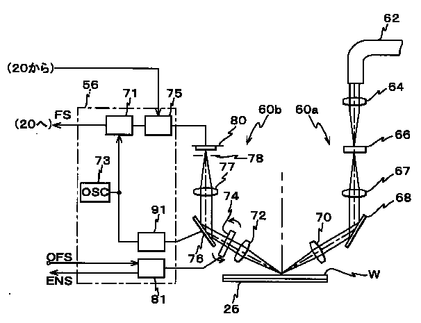
図5には、この多点AF系(60a,60b)、及び該多点AF系(60a,60b)の出力信号を処理するとともに、後述する平行平板ガラス(プレーンパラレル)を駆動する処理駆動部56(図1参照)の構成が概略的に示されている。この図5では、投影光学系PLの最良結像面とウエハWの表面が一致しているものとする。
【0094】
前記照射系60aは、図5に示されるように、光ファイバ束62、集光レンズ64、パターン形成板66、レンズ67、ミラー68、及び縮小レンズから成る照射対物レンズ70等を備えている。また、前記受光系60bは、拡大レンズから成る受光対物レンズ72、平行平板ガラス74、回転方向振動板76、結像レンズ77、受光用スリット板78、及び多数のセンサとしてのフォーカスセンサを有する受光器80等を備えている。
【0095】
ここで、照射系60a及び受光系60bを構成する上記各部についてその作用とともに説明する。露光光とは異なるウエハW上のフォトレジストを感光させない波長の照明光が、図示しない照明光源から光ファイバ束62を介して導かれている。光ファイバ束62から射出された照明光は、集光レンズ64を経てパターン形成板66を照明する。
【0096】
このパターン形成板66上には不図示の49個のスリット状の開口パターンが7行7列のマトリックス状配置で形成されており、パターン形成板66の各スリット状の開口パターンを透過した照明光(開口パターンの像光束)はレンズ67、ミラー68及び照射対物レンズ70を経てウエハWの露光面に投影され、ウエハWの露光面にはパターン形成板66上の7×7、合計49個のスリット状の開口パターンの像が投影結像される。ここで、実際には、照射系60aからの開口パターンの像光束は、YZ平面、XZ平面に対し45度を成す平面内で光軸AXに対して所定角度α傾斜した方向からウエハW面(又はスリット板90、あるいは不図示の基準マーク板表面)に照射される。
【0097】
このため、ウエハW表面の所定面積AS(ASは例えば25mm×約10mm)の長方形状の露光領域IA近傍には、図6に示されるように、7行7列のマトリックス状配置で7×7、合計49個のX軸、Y軸に対して45度傾斜したスリット状の開口パターンの像(以下、適宜「スリット像」又は「検出点」という)S11〜S77が、X軸方向に沿って例えば3.5mm間隔、Y軸方向に沿って例えば3.5mm間隔で形成される。これらのスリット像S11〜S77の光束のウエハW面からの反射光束が、光軸AXに対して前記照射系60aからの像光束と対称に所定角度α傾斜した方向に進んで、受光対物レンズ72、平行平板ガラス74、回転方向振動板76及び結像レンズ77を経て受光器80の手前側に配置された受光用スリット板78上に再結像される。
【0098】
これを更に詳述すると、受光器80上にはスリット像S11〜S77に対応して7行7列のマトリックス状に49個のフォトダイオード等のフォトセンサから成るセンサとしてのフォーカスセンサ(以下、便宜上「フォーカスセンサD11〜D77とも」呼ぶ)が配列されており、この受光器80の前面(図5における下面)に配置された受光用スリット板78にはフォーカスセンサD11〜D77に個別に対向して49個のスリットがそれぞれ形成されており、これらのスリット上にそれぞれ図6に示されるスリット像S11〜S77がそれぞれ再結像される。なお、以下の説明において、複数のフォーカスセンサを纏めて呼ぶ場合、あるいは各フォーカスセンサについて説明をする場合に、適宜「フォーカスセンサD」と記述するものとする。
【0099】
ここで、処理駆動部56には、図5に示されるように、発振器(OSC.)73が内蔵されており、発振器73からの駆動信号でドライブされる加振装置91を介して回転方向振動板76に所定の振動が与えられると、受光用スリット板78上では再結像された各像の位置が所定方向(スリット板78の各スリットの長手方向と直交する方向)に振動する。これにより、フォーカスセンサD11〜D77のそれぞれの検出信号が選択装置75を介して信号処理装置71により、回転振動周波数の信号で同期検波される。そして、この信号処理装置71により同期検波して得られた多数のフォーカス信号FSが主制御装置20に供給される。なお、信号処理装置71、及び選択装置75の構成などについては更に後述する。
【0100】
前記平行平板ガラス74は、駆動部81によってある角度範囲内で回転可能に構成されている。この平行平板ガラス74の回転(傾き)によって、受光用スリット板78上に形成されるスリット像S11〜S77の拡大像(反射スリット像)の振動中心がスリット板78上の各スリットの長手方向と直交する方向にシフトする。その振動中心の各スリットに対するシフトは、フォーカス信号FSが合焦(後述するSカーブ信号波形上の零点)と判断されるときのウエハWの位置を、Z軸方向にシフトしたものと等価である。
【0101】
本実施形態では、平行平板ガラス74の回転駆動機構に設けられた不図示のロータリエンコーダの出力ENSが主制御装置20に供給され、主制御装置20ではそのロータリエンコーダの出力ENSに基づいて簡単な演算を行って平行平板ガラス74の回転角を算出するようになっている。かかる詳細は、例えば特開昭61−183928号公報などに開示されている。
【0102】
前記駆動部81には、主制御装置20からのオフセット指令値(OFS)が駆動信号として与えられるようになっている。例えば、主制御装置20では、多点AF系(60a、60b)の後述するキャリブレーション時などにおいて、多点AF系(60a、60b)の各フォーカスセンサDの検出オフセットを調整するため、調整量に応じたオフセット指令値(OFS)を駆動信号として駆動部81内のモータドライバに与えて平行平板ガラス74の傾き量(回転角θ)を制御することができるようになっている。
【0103】
これまでの説明から明らかなように、本実施形態の場合、ウエハW上の検出点であるスリット像S11〜S77のそれぞれと受光器80上のフォーカスセンサD11〜D77とが1対1で対応し、各スリット像の位置のウエハW表面のZ位置の情報(フォーカス情報)が各フォーカスセンサDからの出力であるフォーカス信号FSに基づいて得られる。
【0104】
前記選択装置75は、ここでは、マイクロプロセッサを含んで構成され、この選択装置75には、逆バイアス電圧が印加されたフォーカスセンサD11、D12、……D77が不図示のスイッチ回路を介して接続されている。この選択装置75には、n本の出力線を介して信号処理装置71が接続されている。なお、以下の説明においては、一例としてn=12の場合について説明する。
【0105】
選択装置75は、所定の基準に基づいて、最大12本の出力線のそれぞれにスイッチ回路を介して49個のフォーカスセンサD11、D12、……D77の内のいずれかを接続することにより、その出力線の一部を少なくとも含むフォーカスセンサの光電変換回路を閉じ、任意のフォーカスセンサの出力信号(任意のフォーカスセンサDの受光する光の強さに応じた光電流)を12本の出力線の内の所望の出力線を介して信号処理装置71に送るようになっている。すなわち、選択装置75は、上述のようにして49個のフォーカスセンサの内から最大12個のフォーカスセンサを選択することにより、実質的に49個のフォーカスセンサの中からウエハWのフォーカス・レベリング制御などに用いられる最大12個のフォーカスセンサ、すなわち検出点を選択する。
【0106】
前記信号処理装置71は、12本の出力線にそれぞれ接続された12個の信号処理回路と、これに接続された出力回路とを備えている。各信号処理回路には位相同期検波回路(PSD)が内蔵されており、このPSDには発振器73からの駆動信号と同じ位相の交流信号が入力されている。そして、各信号処理回路では、各出力線からの信号を上記の交流信号の位相を基準としてそれぞれ同期整流(同期検波)を行ない、ウエハW上の各スリット像S11〜S77の場所のZ軸方向位置(フォーカス位置)に対応するフォーカス信号(焦点位置検出信号)FSを生成する。そして、信号処理回路からのフォーカス信号FSは、出力回路によりデジタル変換され、シリアルデータとして主制御装置20に出力されるようになっている。
【0107】
ところで、各フォーカス信号FSは、いわゆるSカーブ信号と呼ばれ、受光用スリット板78の各スリット中心とウエハWからの反射スリット像の振動中心とが一致したときに零レベルとなり、ウエハWがその状態から上方に変位しているときは正のレベル、ウエハWが下方に変位しているときは負のレベルになる信号である。従って、各フォーカス信号FSにオフセットが加えられていない状態では、主制御装置20によって、各フォーカス信号FSが零レベルになるウエハWの高さ位置(光軸方向位置)が合焦点としてそれぞれ検出されることになる。
【0108】
なお、主制御装置20では、後述する走査露光時等に、受光系60bからのフォーカス信号FSに基づいて不図示のウエハステージ駆動系を介してウエハテーブル54のZ軸方向への移動に加え、2次元的な傾斜(すなわち、θx,θy方向の回転)をも制御する、すなわち多点AF系(60a、60b)を用いてウエハテーブル54の移動を制御することにより、照明光ILの照射領域(照明領域IARと結像関係)内で投影光学系PLの結像面とウエハWの表面とを実質的に合致させるオートフォーカス(自動焦点合わせ)及びオートレベリングを実行する。
【0109】
さらに、本実施形態の露光装置では、図示は省略されているが、ウエハW上のアライメントマーク(位置合わせマーク)、基準平面部材58上のスリット22、あるいは不図示の基準マーク板上の基準マークなどを検出するオフアクシス・アライメント系が投影光学系PLの鏡筒の側面に配置されている。このアライメント系としては、例えばウエハW上のレジストを感光させないブロードバンドな検出光束を対象マークに照射し、その対象マークからの反射光により受光面に結像された対象マークの像と不図示の指標の像とを撮像素子(CCD等)を用いて撮像し、それらの撮像信号を出力する画像処理方式のFIA(Field Image Alignment)系のセンサが用いられる。なお、FIA系に限らず、コヒーレントな検出光を対象マークに照射し、その対象マークから発生する散乱光又は回折光を検出したり、その対象マークから発生する2つの回折光(例えば同次数)を干渉させて検出するアライメントセンサを単独であるいは適宜組み合わせて用いることは勿論可能である。
【0110】
前記主制御装置20は、ワークステーション(又はマイクロコンピュータ)などから成り、この主制御装置20には、図1に示されるように、信号処理回路42、処理駆動部56などが接続されている。また、主制御装置20には、図1に示されるように、ハードディスクなどから成る記憶装置51、及びキーボード、マウス等のポインティングデバイスや、CRT又は液晶パネル等のディスプレイを備えた入出力装置30が併設されている。
【0111】
次に、本実施形態の露光装置100における露光工程の動作について簡単に説明する。
【0112】
まず、不図示のレチクル搬送系によりレチクルRが搬送され、ローディングポジションにあるレチクルステージRSTに吸着保持される。次いで、主制御装置20により、ウエハステージWST及びレチクルステージRSTの位置が制御され、レチクルR上に形成された不図示のレチクルアライメントマークの投影像(空間像)が空間像計測装置59を用いて後述するようにして計測され(図3参照)、レチクルパターン像の投影位置が求められる。すなわち、レチクルアライメントが行われる。
【0113】
次に、主制御装置20により、空間像計測装置59がアライメント系の直下へ位置するように、ウエハステージWSTが移動され、アライメント系によって空間像計測装置59の位置基準となるスリット22が検出される。主制御装置20では、このアライメント系の検出信号及びそのときのウエハ干渉計31の計測値、並びに先に求めたレチクルパターン像の投影位置に基づいて、レチクルRのパターン像の投影位置とアライメント系との相対位置、すなわちアライメント系のベースライン量を求める。
【0114】
かかるベースライン計測が終了すると、主制御装置20により、例えば特開昭61−44429号公報などに詳細に開示されるEGA(エンハンスト・グローバル・アライメント)等のウエハアライメントが行われ、ウエハW上の全てのショット領域の位置が求められる。なお、このウエハアライメントに際して、ウエハW上の複数のショット領域のうちの予め定められた所定のサンプルショットのウエハアライメントマークMwがアライメント系を用いて、前述した如くして計測される(図3参照)。
【0115】
次いで、主制御装置20では、上で求めたウエハW上の各ショット領域の位置情報及びベースライン量に基づいて、干渉計31、13からの位置情報をモニタしつつ、ウエハステージWSTを第1ショット領域の露光のための走査開始位置(加速開始位置)に位置決めするとともに、レチクルステージRSTを走査開始位置に位置決めして、その第1ショット領域の走査露光を行う。
【0116】
すなわち、主制御装置20では、レチクルステージRSTとウエハステージWSTとのY軸方向逆向きの相対走査を開始し、両ステージRST、WSTがそれぞれの目標走査速度に達すると、照明光ILによってレチクルRのパターン領域が照明され始め、走査露光が開始される。この走査露光の開始に先立って、光源の発光は開始されているが、主制御装置20によってレチクルブラインドを構成する可動ブラインド12の各ブレードの移動がレチクルステージRSTの移動と同期制御されているため、レチクルR上のパターン領域外への照明光ILの照射が防止されることは、通常のスキャニング・ステッパと同様である。
【0117】
主制御装置20では、特に上記の走査露光時にレチクルステージRSTのY軸方向の移動速度VrとウエハステージWSTのX軸方向の移動速度Vwとが投影光学系PLの投影倍率に応じた速度比に維持されるようにレチクルステージRST及びウエハステージWSTを同期制御する。
【0118】
そして、レチクルRのパターン領域の異なる領域が紫外パルス光で逐次照明され、パターン領域全面に対する照明が完了することにより、ウエハW上の第1ショット領域の走査露光が終了する。これにより、レチクルRの回路パターンが投影光学系PLを介して第1ショット領域に縮小転写される。
【0119】
こうして第1ショット領域の走査露光が終了すると、ウエハステージWSTを第2ショット領域の露光のための走査開始位置(加速開始位置)へ移動させるショット間のステッピング動作を行う。そして、その第2ショット領域の走査露光を上述と同様にして行う。以後、第3ショット領域以降も同様の動作を行う。
【0120】
このようにして、ショット間のステッピング動作とショットの走査露光動作とが繰り返され、ステップ・アンド・スキャン方式でウエハW上の全てのショット領域にレチクルRのパターンが転写される。
【0121】
ここで、上記の走査露光中には、前述のフォーカスセンサ(60a、60b)を用いて、前述したオートフォーカス・オートレベリングが行われる。
【0122】
ところで、上記の走査露光中に、レチクルRのパターンとウエハW上のショット領域に既に形成されたパターンとが正確に重ね合わせられるためには、投影光学系PLの光学特性やベースラインが正確に計測されていること、及び投影光学系PLの光学特性が所望の状態に調整されていることなどが重要である。また、デフォーカスに起因する露光不良(例えば、いわゆる色むらなど)の発生なども防止するため、多点AF系(60a、60b)の調整が精度良く行われていることも重要である。
【0123】
本実施形態では、上記の光学特性の計測や多点AF系(60a、60b)の調整の際に、空間像計測装置59を用いた空間像計測が行われる。従って、以下、この空間像計測装置59による空間像計測について詳述する。
【0124】
図3には、空間像計測装置59を用いて、レチクルRに形成された計測マークの空間像が計測されている最中の状態が示されている。レチクルRとしては、空間像計測専用のもの、あるいはデバイスの製造に用いられるデバイスレチクルに専用の計測マークを形成したものなどが用いられる。これらのレチクルの代わりに、レチクルステージRSTにレチクルと同材質のガラス素材から成る固定のマーク板(レチクルフィデューシャルマーク板とも呼ばれる)を設け、このマーク板に計測マークを形成したものを用いても良い。
【0125】
ここで、レチクルRには、図3に示されるように、所定の箇所にY軸方向に周期性を有するL/Sパターンから成る計測マークPMが形成されているものとする。また、空間像計測装置59のスリット板90には、図7(A)に示されるように、X軸方向に伸びる所定幅2Dのスリット22が形成されているものとする。
【0126】
空間像の計測に当たり、主制御装置20により、可動レチクルブラインド12がブラインド駆動装置を介して駆動され、レチクルRの照明光ILの照明領域が計測マークPM部分のみに規定される(図3参照)。この状態で、照明光ILがレチクルRに照射されると、図3に示されるように、計測マークPMによって回折、散乱した光(照明光IL)は投影光学系PLにより屈折され、該投影光学系PLの像面に計測マークPMの空間像(投影像)PM’が形成される。このとき、ウエハテーブル54は、空間像計測装置59のスリット板90上のスリット22の+Y側(又は−Y側)に前記空間像PM’が形成される位置に設定されているものとする。このときの空間像計測装置59の平面図が図7(A)に示されている。
【0127】
そして、主制御装置20により、ウエハステージ駆動系を介してウエハテーブル54が図7(A)中に矢印Fで示されるように+Y方向に駆動されると、スリット22が空間像PM’に対してY軸方向に沿って走査される。この走査中に、スリット22を通過する光(照明光IL)がウエハテーブル54内の光導出部、及び受光レンズ89を介して光センサ24で受光され、その光電変換信号が信号処理回路42を介して主制御装置20に供給される。主制御装置20では、その光電変換信号に基づいて空間像PM’に対応する光強度分布を計測する。
【0128】
図7(B)には、上記の空間像計測の際に得られる光電変換信号(光強度信号)Pの一例が示されている。
【0129】
この場合、空間像PM’はスリット22の走査方向(Y軸方向)の幅(2D)の影響で像が平均化する。
【0130】
従って、スリットをp(y)、空間像の強度分布をi(y)、観測される光強度信号をm(y)とすると、空間像の強度分布i(y)と観測される強度信号m(y)の関係は次の(1)式で表すことができる。この(1)式において、強度分布i(y)、強度信号m(y)の単位は単位長さ当たりの強度とする。
【0131】
【数1】
【数2】
すなわち、観測される強度信号m(y)はスリッ卜p(y)と空間像の強度分布i(y)のコンボリューションになる。
【0134】
従って、計測精度の面からは、スリット幅2Dは、小さいほど良く、本実施形態のようにPMTを光センサ24として用いる場合には、スリット幅が非常に小さくなっても走査速度を遅くして計測に時間を掛ければ光量(光強度)の検出は可能である。しかしながら、現実には、スループットの面から空間像計測時の走査速度には、一定の制約があるため、スリット幅2Dがあまりにも小さいと、スリット22を透過する光量が小さくなり過ぎて、計測が困難となってしまう。
【0135】
発明者がシミュレーション及び実験等により得た知見によれば、スリット幅2Dの最適値は、露光装置の解像限界ピッチ(デューティ比50%のL/Sパターンのピッチ)の半分程度となることが確認されたので、本実施形態では、そのように設定したものである。
【0136】
なお、前述の如く、スリット板90上には、第1スリット22y、第2スリット22xの計測方向が異なる2種類のスリットが設けられているが、これらを用いた空間像計測に際してその計測方向に対応する計測マークが用いられ、計測マークの投影像(空間像)の向きに平行なスリットだけに空間像が重なるようにスリット板90を空間像に対して走査するようになっている。
【0137】
上述した空間像計測装置59及びそれを用いた空間像計測方法は、a.ベストフォーカス位置の検出、b.XY面内でのパターン像の結像位置の検出、c.アライメント系のベースライン計測等に用いられる。
【0138】
本実施形態の露光装置100におけるc.ベースライン計測については既に説明した。また、b.XY面内でのパターン像の結像位置の検出は、本発明との関連が薄いため、以下、上記a.ベストフォーカス位置の検出について、説明する。
【0139】
このベストフォーカス位置の検出は、例えば投影光学系PLのベストフォーカス位置の検出及び最良結像面(像面)の検出などの目的に用いられる。
【0140】
本実施形態では、一例として次のようにして投影光学系PLのベストフォーカス位置の検出を行う。
【0141】
このベストフォーカス位置の検出には、例えば、解像限界付近の1次元方向(ここではY軸方向)に所定ピッチで配列された複数本ラインパターンから成るデューティ比50%の周期パターン、すなわちいわゆるロンキーグレーティング状のパターンが、計測マークPMとして形成されたレチクルRが用いられる。
【0142】
まず、不図示のレチクルローダにより、レチクルステージRST上にレチクルRがロードされる。次に、主制御装置20では、投影光学系PLの視野内でベストフォーカス位置を計測すべき所定点(ここでは投影光学系PLの光軸上)にレチクルR上の計測マークPMが位置決めされるように、レチクルステージRSTを移動する。
【0143】
次に、主制御装置20では、照明光ILが計測マークPM部分のみに照射されるように可動レチクルブラインド12を駆動制御して照明領域を規定する。この状態で、主制御装置20では、照明光ILをレチクルRに照射して、前述と同様にして、ウエハテーブル54をY軸方向に走査しながら空間像計測装置59を用いて、計測マークPMの空間像計測を前述と同様にスリットスキャン方式により行う。この際、主制御装置20では、スリット板90のZ軸方向の位置(すなわち、ウエハテーブル54のZ位置)を例えば0.1μmピッチで15ステップ程度)変化させつつ、複数回繰り返し、各回の光強度信号(光電変換信号)を内部メモリに記憶する。ステップ範囲は、例えば設計上のベストフォーカス位置をほぼ中心とする範囲で行われる。
【0144】
主制御装置20は、上述のようにして内部メモリに記憶された光強度信号をそれぞれフーリエ変換し、それぞれの1次周波数成分と0次周波数成分の振幅比であるコントラストを評価量としてを求める。このコントラストはフォーカス位置によって敏感に変化するので強度信号からベストフォーカス位置を決定するのに便利である。そして、主制御装置20では、一例として、横軸をフォーカス位置(Z位置)とし、縦軸をコントラストする座標系上に得られたコントラスト値のデータをプロットし、そのプロットデータを適当な関数(2次以上、例えば4〜6次関数)でフィッティングしてその関数曲線(以下、「コントラストカーブ」と呼ぶ)がピーク値を示すZ位置を算出することでベストフォーカス位置を求める。
【0145】
次に、本実施形態の露光装置100で行われる多点AF系の調整方法について詳述する。この多点AF系の調整は、以下のa.〜c.の3つのステップに分けられる。
a.多点AF系の光学調整(粗調整)
b.センサ間オフセットの調整(多点AF系のファイン調整)
c.フォーカスセンサ面キャリブレーション(フォーカスセンサ面の経時変化の管理)
【0146】
本実施形態のような多点AF系(60a,60b)では、検出点(スリット像)S11〜S77それぞれに対応するフォーカスセンサD11〜D77の検出原点の投影光学系PLのベストフォーカス面(最良結像面)からの相対距離(Z軸方向の位置ずれ量)を正確に計測する必要がある。
【0147】
多点AF系(60a,60b)では、前述の如く回転方向振動板76を変調器として用い、スリット像S11〜S77の反射スリット像の受光用スリット板78上の各スリットに対する位置ずれ量をウエハW表面のZ位置に読み替えてフォーカス計測を行うようになっている。そのため、機械的な原点に対して反射スリット像の位置ずれ誤差分のオフセットが生じる。これは複数のフォーカスセンサで光学系を共用する多点AF系では必ず生じる現象で、全てのフォーカスセンサのオフセットを機械的にゼロとするのは困難である。
【0148】
また、多点AF系を構成する複数のフォーカスセンサの検出原点の集合によって形成される面の近似平面(以下、「フォーカスセンサ面」と呼ぶ)を完全に投影光学系の像面の近似平面に一致させることが理想的であるが現実的にはある程度機械的な誤差が生じる。
【0149】
以上のような種々の原点ずれの成分は記録可能なデータとして管理する必要がある。本実施形態の多点AF系のような光電式フォーカスセンサは被検面の原点からの光軸方向に関する距離に略比例した電圧値の信号を出力する。これは、前述の如くSカーブ信号と呼ばれており、Z位置と電圧との関係を予め計測しておけば電圧値から正確な被検面のZ位置を測定することが出来る。Z位置の原点ずれ、すなわち各フォーカスセンサDの検出原点の機械的な原点からのずれ量は残留オフセットとしてデジタルデータ等の記憶可能なデータに変換して、主制御装置20に接続された記憶装置51あるいは内部メモリなどに記憶しておけば各フォーカスセンサの正確な原点(検出オフセット)を管理することが可能になる。
【0150】
多点AF系の各フォーカスセンサの最終的な検出オフセットを計測する前に、多点AF系のキャプチャーレンジ内(例えば原点を中心とする±10μm程度の範囲内)に投影光学系PLの像面を位置させる必要がある。光学調整の初期の段階では必ずしも多点AF系の各フォーカスセンサのキャプチャーレンジ内に像面が位置するとは限らない。
【0151】
そのため、本実施形態では、主制御装置20は、多点AF系(60a,60b)の中央1点の検出点S44のみを用いて、投影光学系PLの像面(この場合検出点S44のベストフォーカス位置)を計測することとしている。これは、多点AF系であっても、中央1点の検出点のみを用いて計測する場合には、前述の平行平板ガラス74の角度を変化させることにより、キャプチャーレンジを中立点(真の原点)を中心とする±50μm程度の範囲まで拡大可能であるので光学調整が精密になされていなくても、投影光学系PLの像面にフォーカスの原点を設定することが可能だからである。
【0152】
本実施形態では、この多点AF系の光学調整に際し、投影光学系PLの視野内の一部領域(固定レチクルブラインドの開口で設定可能な矩形領域(前述の照明領域IARに対応))内の複数の評価点(光軸上の評価点を含む)に対応して計測マークPMが形成されたレチクル(便宜上、「レチクルR1」と呼ぶ)が用いられる。
【0153】
そして、主制御装置20では、平行平板ガラス74が任意の傾斜角度に設定された初期状態で、空間像計測装置59を用いて投影光学系PLの光軸上の評価点におけるベストフォーカス位置の計測を次のようにして試みる。
【0154】
まず、不図示のレチクルローダにより、レチクルステージRST上にレチクルR1がロードされる。次に、主制御装置20では、レチクルR1上の中心に位置する計測マークPM(以下、識別のため「PM1」と記述する)が、投影光学系PLの光軸上に一致するように、レチクルステージRSTを位置決めする。
【0155】
次いで、投影光学系PLの光軸上の第1検出点に対応する計測マークPM1部分にのみ照明光ILが照射されるように、可動レチクルブラインド12を駆動制御して照明領域を規定する。
【0156】
この状態で、主制御装置20では、照明光ILをレチクルRに照射して、前述と同様にして、スリットスキャン方式により空間像計測装置59を用いて計測マークPMの空間像計測を、スリット板90のZ軸方向位置を所定ステップピッチで変化させながら繰り返し行う。その際に、主制御装置20では、検出点S44に対応するフォーカスセンサD44のみを選択装置75を介して選択し、そのフォーカスセンサD44の検出値のみに基づいて基準平面部材58のスリット板90のZ軸方向の位置を制御する。また、スリット板90の傾き、すなわちウエハテーブル54の投影光学系PLの光軸に直交するXY平面に対する傾斜は、前述したウエハ干渉計31、より正確には、ウエハテーブル54のピッチング、ローリングをそれぞれ検出する測長軸を有する一対のY干渉計(ピッチング干渉計として機能する)、X干渉計(ローリング干渉計として機能する)の計測値に基づいて、所望の一定角度となるように(例えばピッチング、ローリングがともに零となるように)制御することとしても良い。
【0157】
そして、主制御装置20では、その空間像の計測結果に基づいて前述と同様にして得られたコントラストカーブがピーク値を示すZ位置があるか否かを判断し、その判断が否定された場合には、駆動部81に適当なオフセット指令値(OFS)を駆動信号として与えて、平行平板ガラス74を所定量回転駆動して、再度、上記のベストフォーカス位置の計測を行う。このようにして、主制御装置20では、平行平板ガラス74を所定量づつ回転しながら、ベストフォーカス位置の計測、コントラストカーブの算出を繰り返し、コントラストカーブにピーク値があらわれた段階で、そのピーク値に対応する光軸方向に関する位置Z1を算出し、その位置Z1を検出点S44にほぼ一致する投影光学系PLの光軸上の評価点におけるベストフォーカス位置として内部メモリに記憶する。
【0158】
次に、投影光学系PLの視野内の一部領域、すなわち前述の矩形領域(前述の照明領域IARに対応)内の複数の評価点におけるベストフォーカス位置の計測、すなわち投影光学系PLの像面の計測を、空間像計測装置59を用いて行うが、この方法としては、次の2つの方法を採用することが可能である。
【0159】
<第1の像面計測方法>
主制御装置20では、投影光学系PLの視野内の第2評価点に対応するレチクルR1上の計測マークPM(以下、識別のため「PM2」と記述する)部分にのみ照明光ILが計測マークPM部分のみに照射されるように可動レチクルブラインド12を駆動制御して照明領域を規定する。この状態で、上記と同様に、フォーカスセンサD44あるいは第2評価点の近傍の1つの検出点に対応するフォーカスセンサDの検出値のみに基づいて基準平面部材58のスリット板90のZ軸方向の位置を制御するとともに、スリット板90の傾きをウエハテーブル54のピッチング、ローリングをそれぞれ検出する一対のY干渉計(ピッチング干渉計として機能する)、X干渉計(ローリング干渉計として機能する)の計測値に基づいて制御して、スリットスキャン方式で計測マークPM2の空間像計測及び第2評価点におけるベストフォーカス位置Z2の検出を行って、その結果を内部メモリに記憶する。
【0160】
以後、主制御装置20では、上記と同様に、投影光学系PLの視野内の評価点を変更しつつ、計測マークPMについて空間像の計測及び投影光学系PLのベストフォーカス位置の検出を繰り返し行う。なお、主制御装置20は、第2評価点以降のベストフォーカス位置の計測に際しては、先に求めた位置Z1を中心とする+Z側、−Z側の所定幅の範囲で、所定ステップピッチでスリット板90のZ位置を変更しながら、空間像計測を行う。
【0161】
そして、主制御装置20は、上述のようにして得られた各ベストフォーカス位置Z1、Z2、……、Znに基づいて、所定の統計的処理を行うことにより、投影光学系PLの像面の近似平面(及び像面形状)を算出する。このとき、像面形状とは別に像面湾曲を算出することも可能である。
【0162】
投影光学系PLの像面、すなわち、最良結像面は、光軸からの距離が異なる無数の点(すなわち、いわゆる像の高さが異なる無数の点)におけるベストフォーカス点の集合から成る面であるから、このような手法により、像面形状及びその近似平面を容易にかつ正確に求めることができる。
【0163】
この第1の像面計測方法は、基準平面部材58(スリット板90)のスリット22の近傍で平面度が悪化している場合に、その位置を避けてフォーカス計測、管理などを行う必要がある場合にメリットがある。例えば図4(B)の遮光膜(クロム膜)91の部分と反射膜(アルミニウム膜)83部分の境界はプロセス上レジストが残留しがちであるが、そのような場合にその境界部分に掛からない中央1点の検出点のみを用いてフォーカス計測を行うことができる。この一方、後述するように、スリット板90を基準平面板として使用する場合には、クロム膜部分に多点AF系の検出点(スリット像)が掛からないようにすることが肝要である。従って、上述の場合においても、仮に検出点S44が上記の境界に掛かるような場合には、その近傍の検出点で境界に掛からない検出点に対応するフォーカスセンサ(フォーカスセンサ)Dを用いて、前述のフォーカス計測及び像面計測を行う必要がある。
【0164】
なお、この第1の像面計測方法において、主制御装置20では、ウエハテーブル54を駆動する駆動装置内の前述の3つ(一組)のエンコーダ28の出力に基づいて前述のスリット板90の傾斜を制御することとしても良い。
【0165】
<第2の像面計測方法>
この第2の像面計測方法は、投影光学系PLの視野内の複数の評価点のそれぞれでその近傍に位置する検出点Sに対応するフォーカスセンサD、例えば露光領域IAの4隅及び中央に位置する合計5点の検出点S31、S51、S44、S37、S57に個別に対応するフォーカスセンサD31、D51、D44、D37、D57を選択し、それらのフォーカスセンサDの計測値に基づいて前述した像面計測の際のスリット板90のZ軸方向の位置及び傾斜を制御する点が前述の第1の像面計測方法と異なり、その他の点は、前述の第1の像面計測方法と同様である。
【0166】
そして、主制御装置20は、この場合にも得られた各ベストフォーカス位置Z1、Z2、……、Znに基づいて、所定の統計的処理を行うことにより、投影光学系PLの像面の近似平面(及び像面形状)を算出する。また、必要であれば、像面湾曲を算出しても良い。なお、この第2の像面計測方法の利点については、後述する。
【0167】
次に、主制御装置20では、上述のようにして求められた投影光学系PLの像面の近似平面に、基準平面板の機能を有するスリット板90表面がなるべく平行になるように、その時点の調整状態の多点AF系(60a、60b)を用いて、ウエハテーブル54の傾斜をステージ駆動系を介して制御する。次いで、主制御装置20では、この状態でウエハテーブル54のZ位置及び傾斜が維持されるように、前述のエンコーダ28を用いたサーボ制御を行いつつ、多点AF系(60a、60b)の光学調整を行う。この光学調整は、スリット板90の表面が多点AF系(60a、60b)の複数(この場合最大12個)のフォーカスセンサDの検出原点の近似平面から成る面(フォーカスセンサ面)が平行になるように、すなわち、選択された12個のフォーカスセンサの検出オフセットがなるべく平均化されるように、駆動部81を介して平行平板ガラス74の傾斜角を調整することにより行われる。
【0168】
なお、本実施形態では、レチクルR1に複数の計測マークPMを形成しておき、可動レチクルブラインド12によって各計測マークPMに照明光ILを順次照射して、それぞれの計測マークに対応する投影光学系PLの評価領域においてベストフォーカス位置を検出することとしたが、これに限らず、レチクルを移動してベストフォーカス位置を計測すべき複数点にそれぞれ計測マークPMを配置することとしても良い。この場合には、計測マークPMが1つだけのレチクルを用いることができる。また、レチクルステージRST上に基準板を設け、この基準板上に複数の計測マークPMを形成しても良い。
【0169】
b.センサ間オフセットの調整(多点AF系のファイン調整)
この多点AF系のファイン調整は、フォーカスセンサD11〜D77個々の個体差及び調整誤差などに起因する相対的な計測誤差を極限まで小さく抑えるために必要な工程である。
【0170】
この多点AF系のファイン調整では、平坦度の良好な平面板、例えば前述のスリット板90、スーパーフラットウエハあるいはウエハなどを、投影光学系PLの像面の近似平面に平行な状態に設定し、その平面板の傾きを維持しつつ、多点AF系の複数のフォーカスセンサ間の計測値の相対的なオフセットを計測する。この多点AF系のファイン調整では、スリット板90などの平面板が搭載されたウエハテーブル54の静止性が上述のセンサ間オフセット計測にとって重要である。このため、本実施形態では、多点AF系のファイン調整中は、ウエハテーブル54を多点AF系(60a、60b)の計測値に基づくサーボモード(フォーカスサーボモード)で制御する。すなわち、このフォーカスサーボモードでは、多点AF系(60a、60b)の複数のフォーカスセンサの中から選択された複数のフォーカスセンサの計測値を目標値(与えられた検出オフセット)と比較しながらサーボ制御が行われるため、前述したピッチング干渉計やローリング干渉計だけでウエハテーブル54を静止させる(姿勢を一定状態に維持する)よりも投影光学系PLに対して安定してスリット板90の姿勢を制御できる。
【0171】
主制御装置20は、例えば投影光学系PLの視野内の5点の検出点、例えば検出点S31、S51、S44、S37、S57に個別に対応するフォーカスセンサD31、D51、D44、D37、D57それぞれに、スリット板90を投影光学系PLの像面の近似平面に平行な状態にするのに必要な検出オフセットを目標値として与え、それらのフォーカスセンサD31、D51、D44、D37、D57を用いてスリット板90の姿勢をサーボ制御しつつ、そのサーボ制御に使用されていない残り44個のフォーカスセンサDの検出オフセット(計測値)を取り込み、それらの値を内部メモリに記憶する。このとき、サーボ制御に使用するフォーカスセンサD31、D51、D44、D37、D57の目標値としてそれぞれ与えるべき検出オフセットは、上記の多点AF系(60a、60b)の光学調整後に前述の第1、第2の像面計測方法と同様の計測を再度行うことにより計測することが可能である。
【0172】
但し、例えば前述の第2の像面計測方法により像面計測を行った場合には、その際に得られた選択されたフォーカスセンサの近傍の評価点におけるベストフォーカス位置に対するその選択されたフォーカスセンサD31、D51、D44、D37、D57の検出オフセット値を、そのまま用いることが可能である。換言すれば、前述の多点AF系の光学調整の工程では、すなわち、前述した第2の像面計測方法では、その像面計測の際に、その後に続いて行われるセンサ間オフセットの調整の際にフォーカスサーボ時に各フォーカスセンサに与えるべきフォーカスオフセット値をその段階で入手できるという大きなメリットを有している。この意味からすると、多点AF系の光学調整の工程では、前述の第2の像面計測方法を採用した方が、調整時間の短縮を図るという点では望ましいと言える。
【0173】
上述の44点の検出点に個別に対応する44個のフォーカスセンサDの検出オフセットの計測が終了すると、主制御装置20では、それら44個のフォーカスセンサDの中から、その検出点がなるべく周辺部に位置する複数点、例えば6点の検出点Sに個別に対応するフォーカスセンサDを選択し、それらのフォーカスセンサDの計測値を目標値(上記で検出した検出オフセット)と比較しながらフォーカスサーボモードでスリット板90を制御し、最初にフォーカスサーボモードに用いた5つのフォーカスセンサの検出オフセットを再度計測して、その結果を内部メモリに記憶する。これにより、多点AF系(60a、60b)のファイン調整が終了する。
【0174】
ここで、本実施形態の露光装置100で行われる、上記のフォーカスサーボによる、センサ間オフセットの計測、調整方法は、ウエハテーブル54の制御性だけではなく、空気揺らぎの影響の排除の観点からも非常に有効である。その理由は、複数のフォーカスセンサDは、それぞれの検出点Sが高々20mm程度しか離れていないとともに、これに対応してフォーカスセンサ同士も互いに近接した位置に配置されているので、空気揺らぎが各フォーカスセンサDに与える影響は、センサ間ではほぼ均一であることから、空気揺らぎはフォーカスサーボにより計測値からはキャンセルされているからである。
【0175】
本実施形態の露光装置100では、以上のような手順で調整が行われた多点AF系(60a、60b)を用いて、例えば前述の走査露光中などに前述のオートフォーカス・オートレベリングが行われるので、デフォーカスに起因する色むらなどのない、高精度なレチクルパターンの転写像のウエハ上での形成が可能となる。
【0176】
また、前述した手法により空間像計測装置59を用いて計測された投影光学系PLの像面形状や像面湾曲などが正確に計測され、この計測結果に基づいて、主制御装置20により投影光学系PLの光学特性が不図示の調整装置を介して精度良く調整される。そして、この光学特性が調整された投影光学系PLを用いて前述の走査露光が行われるので、レチクルパターンとウエハW上のショット領域に既に形成されたパターンとを正確に重ね合わることが可能となる。
【0177】
c.フォーカスセンサ面キャリプレーション(フォーカスセンサ面の経時変化の管理)
露光装置100などの投影露光装置では、その使用中の投影光学系に照射される照明光を吸収することや、設置環境の大気圧の変化、その他の変動要因により、投影光学系の光学特性、例えば像面形状や像面傾斜などが経時的に変化することが知られている。このような場合には、そのような像面形状や像面傾斜などの変化をモニタするとともに、それに応じて多点AF系(60a、60b)の調整、すなわちフォーカスセンサ面キャリブレーションを行う必要がある。
【0178】
また、像面傾斜やフォーカスセンサ面のキャリブレーションは、本実施形態の露光装置100のように、空間像計測装置59を備える場合には、空間像計測を用いた各種計測のためにも、像面傾斜などの経時変化に起因するフォーカスセンサ面のキャリブレーションが重要である。その理由は次の通りである。
【0179】
空間像位置計測などの空間像計測に際しては、像面の近似平面内あるいは像面と平行で光軸方向に所定距離隔てた面(目標走査面)内でスリット22を空間像に対してスキャンする。この場合に、像面とスリットとの光軸方向の相対距離が変わると収差の影響が変化し、その結果空間像の計測結果が異なることとなるため、かかる事態の発生を防止するためにも、スリット22(スリット板90)を上記の目標走査面内で正確に走査する必要があるからである。
【0180】
投影光学系PLの視野内の複数の評価点について、前述した方法により、空間像計測装置59を用いたベストフォーカス位置の計測を実行すれば、その計測結果に基づいて像面の近似面が求まり、その結果、その近似面とフォーカスセンサ面との相対的な傾きが求まる。
【0181】
投影光学系PLの光学特性が何らかの原因により経時変化した場合も、上述の空間像計測を利用した像面形状、あるいは像面の近似平面の計測により、その経時変化をモニタすることが可能である。そして、経時変化が検出された場合には多点AF系(60a、60b)の複数のフォーカスセンサの検出オフセットを再度計測して、以前に計測されていたオフセット値を更新する必要がある。
【0182】
多点AF系(60a、60b)の全検出点について空間像計測装置59を用いた計測マークのベストフォーカス位置の計測を利用したフォーカスセンサの検出オフセット計測を実行しても良いが、本実施形態の露光装置100では、次のようにして、フォーカスセンサ面のキャリブレーションを、定期的にあるいは必要に応じて行うようになっている。
【0183】
すなわち、主制御装置20では、投影光学系PLの視野内の3箇所以上の同一の評価点(各評価点は多点AF系の検出点の近傍に存在する)において、前述の空間像計測装置59を用いたベストフォーカス位置の計測を行う、前述の第2の像面計測方法を実行することにより、フォーカスセンサ面と投影光学系PLの像面(あるいはその近似平面)との相対的な角度変化をモニタしている。
【0184】
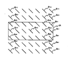
図8には、一例として、視野内の5箇所の検出点S31、S51、S44、S37、S57に個別に対応するフォーカスセンサD31、D51、D44、D37、D57の検出原点によって構成されるフォーカスセンサ面FP、上記5箇所の検出点S31、S51、S44、S37、S57それぞれの近傍の空間像コントラストカーブACに基づいて求められた投影光学系PLの像面の近似平面IPと、前記同様にして求められた投影光学系PLの像面の近似平面IP’との関係が、模式的に示されている。
【0185】
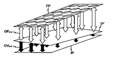
そして、このようにして、図8に模式的に示されるように、フォーカスセンサ面FPからの投影光学系PLの像面IPの角度変化が計測された場合に、主制御装置20は、図9に模式的に示されるように、角度の変化から各フォーカスセンサの検出オフセットの補正値(図9中の黒矢印CVp,q参照)を演算にて求め、その補正値をもとの検出オフセット(図9中の白矢印OFp,q)に加算して新たな検出オフセットとする。このようにすることにより、投影光学系PLの視野内の最低3点の評価点における空間像計測により、多点AF系(60a、60b)の全ての検出点に個別に対応するフォーカスセンサD11〜D77の全てについて、検出オフセット(フォーカスオフセット)を更新することが可能となり、多点AF系(60a、60b)の全検出点について空間像計測装置59を用いた計測マークのベストフォーカス位置の計測を利用したフォーカスセンサの検出オフセット計測を行う場合に比べて、短時間で、かつ同等の精度でフォーカスセンサ面のキャリブレーションを行うことが可能となる。
【0186】
ところで、投影光学系PLの像面形状を正確に計測するためには、投影光学系PLの視野内の任意の評価点で空間像計測、及びその計測時のスリット板90の光軸方向に関する位置の計測が正確に行われる必要がある。このためには、スリット板90は、その表面の平坦度が極力高いことが望ましく、スリット板90のスキャン中は常時フォーカスサーボによりその姿勢が制御されるべきである。
【0187】
しかるに、スリット板90の中心には前述のクロム膜から成る遮光膜91が存在し、特にその遮光膜91と周囲の反射膜83との境界で平坦度が悪化している。
【0188】
そこで、本実施形態では、像面形状そのものを計測するに際しては、主制御装置20が、上記の境界にその検出点がかかるフォーカスセンサを選択装置を介して選択し、フォーカスサーボモードでスリット板90をスキャンするアルゴリズムが採用されている。
【0189】
このように、本実施形態では、多点AF系(60a、60b)と基準平面板を兼ねたスリット板90を備えた空間像計測装置59との組み合わせ採用して、前述の像面計測などを行うことにより、正確に投影光学系PLの像面とスリット22との相対位置を管理できるようになっている。
【0190】
なお、このような計測は多点AF系(60a、60b)の光学調整前には困難であるが、いったん調整された後は、あらゆる計測に際して、前述のフォーカスサーボモードによるウエハテーブル54の制御を行うことが望ましい。
【0191】
これまでの説明から明らかなように、本実施形態では、主制御装置20によって制御装置、検出装置、演算装置が構成され、空間像計測装置59と主制御装置20とによって計測装置が構成され、ウエハ干渉計31と主制御装置20とによって傾斜検出系が構成されている。但し、これに限らず、例えば主制御装置20によって構成される、制御装置、検出装置、演算装置などの構成各部の全てあるいは一部を、複数のハードウェアによって構成しても良い。
【0192】
以上詳細に説明したように、本実施形態の露光装置100によると、多点AF系(60a、60b)の調整、例えば複数のフォーカスセンサの検出原点のオフセット調整などのため、各フォーカスセンサの検出原点と投影光学系PLの像面との位置関係を計測する際に、多点AF系の照射系60aからの複数の検出光束が照射される物体として、その一部に空間像計測が可能なスリット22を有し、その表面の平坦度が高く設定された基準平面部材58が用いられている。このため、その基準平面部材58を用いた空間像計測により、前述の如く、投影光学系PLの像面の計測が可能となる。また、複数のフォーカスセンサの検出原点のオフセット計測の際に、多点AF系を用いて基準平面部材58(より正確には、スリット板90)を投影光学系PLの像面に位置させることにより、そのオフセット計測を精度良く行うことが可能となる。従って、レジスト塗布、露光及び現像等を経ることなく、多点AF系(60a、60b)高精度な調整を、短時間で行うことが可能となる。
【0193】
これを更に詳述すると、本実施形態の露光装置100によると、多点AF系(60a、60b)の調整、特に前述のファイン調整に際して、主制御装置20が、多点AF系の複数の検出点S11〜S77のうちの一部の検出点に対応するフォーカスセンサDを用いて常時その一部の検出点(例えば検出点S31、S37、S44、S51、S57)におけるその検出対象の物体である基準平面部材58(スリット板90)表面の投影光学系PLの光軸方向に関する位置を検出しながら、その基準平面部材58表面が予め、例えば前述の光学系調整工程で計測された既知の投影光学系PLの像面に一致するように基準平面部材58が搭載されたウエハテーブル54の位置を制御するとともに、一部の検出点を除く残りの検出点に個別に対応する各フォーカスセンサの検出原点の基準平面部材58表面、すなわち投影光学系PLの像面(の近似平面)からの光軸方向に関する位置ずれ量を対応するフォーカスセンサの検出オフセットとして検出する。このため、投影光学系PLの像面に対して安定して基準平面部材58(スリット板90)を一致させた状態で、その位置制御に使用されていない残りのフォーカスセンサの検出オフセットを精度良く求めることが可能となる。
【0194】
また、主制御装置20は、前記検出オフセットの検出後、前記残りの検出点に個別に対応するフォーカスセンサの少なくとも一部を用いて対応する検出点における基準平面部材58表面の光軸方向に関する位置を検出しながら、基準平面部材58表面が既知の投影光学系PLの像面に一致するようにウエハテーブル54の位置を制御するとともに、前記一部の検出点に個別に対応する各フォーカスセンサの検出原点の基準平面部材58表面、すなわち投影光学系PLの像面(の近似平面)からの光軸方向に関する位置ずれ量を対応するフォーカスセンサの検出オフセットとして検出する。これにより、多点AF系(60a、60b)の全てのフォーカスセンサの検出オフセットを精度良く求めることができる。
【0195】
この場合において、基準平面部材58に代えて、スーパーフラットウエハや、スリット22の存在しない基準平面板、あるいはデバイス製造用のウエハなどを、多点AF系の検出対象の物体として用いることは可能である。
【0196】
また、本実施形態の露光装置100によると、多点AF系の調整、特にフォーカスセンサ面のキャリブレーションに際して、主制御装置20は、多点AF系(60a、60b)の複数のセンサの検出原点の集合から形成される近似平面(フォーカスセンサ面)と投影光学系PLの像面の近似平面との成す角度の変化を検出する。次いで、主制御装置20は、その検出された角度の変化に基づいて前記各フォーカスセンサの検出オフセットの補正値を算出するとともに、その算出した補正値を予め検出された対応するフォーカスセンサの検出オフセットに加算して新たな検出オフセットとする。このため、投影光学系PLの像面が経時的に変化した場合などにその像面の経時変化に対応してフォーカスセンサの検出オフセットの補正を簡易かつ正確に行うことが可能となる。この場合において、フォーカスセンサ面と像面との成す角度の変化は、主制御装置20により、空間像計測装置59を用いて、投影光学系の視野内の少なくとも3つの評価点について、空間像計測の手法を利用してベストフォーカス位置の検出を行うことによって検出される。従って、全ての検出点におけるベストフォーカス位置の計測を行うことなく、全てのフォーカスセンサの検出オフセットの調整が可能となる。従って、多点AF系の高精度な調整を短時間に行うことが可能となる。
【0197】
また、本実施形態の露光装置100によると、例えば前述の像面計測やベストフォーカス位置の検出のために空間像計測装置59を用いて空間像を計測する際に、主制御装置20が、多点AF系(60a、60b)の複数のフォーカスセンサの内の少なくとも一部の複数の特定フォーカスセンサの検出結果に基づいてウエハテーブル54上に一体的に設けられたスリット板90表面と投影光学系PLの像面の近似平面との間隔と相対角度とが所望の値となるようにスリット板90の位置・姿勢を制御しながら、ウエハテーブル54と一体的にスリット板90を投影光学系の光軸方向に直交する面上で移動する。この場合、多点AF系(60a、60b)の複数の特定フォーカスセンサの検出結果に基づくサーボ制御(フォーカスサーボ制御)によりスリット板90の投影光学系PLとの間隔を一定に保ち、かつスリット板90と投影光学系PLの像面とを平行に保った状態で、スリット板90を空間像に対して相対走査できるので、高精度な空間像計測が可能となる。
【0198】
この場合において、主制御装置20では、前記特定フォーカスセンサとして、前記複数の検出点のうちスリット板90表面の平坦度の良好な位置に位置する検出点に対応するフォーカスセンサを選択装置を介して選択することができる。このため、上記のフォーカスサーボ制御に際して、スリット板90を投影光学系PLの像面とを正確に平行に保つことが可能となる。
【0199】
また、本実施形態の露光装置100では、例えば前述した第2の像面計測方法の実行に際して、主制御装置20が、投影光学系PLの視野内の複数の評価点毎に選択された該評価点の近傍の検出点にそれぞれ対応する複数の特定フォーカスセンサの検出結果に基づいてスリット板90の投影光学系PLの光軸方向の位置及び姿勢を管理しつつ、スリット板90の光軸方向に関する位置を変化させて、スリット板90を光軸に直交する面内で移動して、複数の評価点それぞれに対応する計測マークPMの空間像を繰り返し計測する。この場合、主制御装置20は、上記のフォーカスサーボ制御によりスリット板90の投影光学系PLとの間隔、傾斜を一定に保った状態で、スリット板90を計測マークの空間像に対して相対走査できるので、高精度な空間像計測が、各評価点毎にかつ光軸方向に関する複数の位置で行われることとなる。そして、その計測結果、すなわち評価点毎の光軸方向の複数の位置における空間像の計測結果に基づいて、主制御装置20が、各評価点におけるベストフォーカス位置を検出するとともに、その検出結果に基づいて所定の演算により投影光学系PLの像面を算出する。従って、短時間でかつ投影光学系の像面を精度良く検出することができる。
【0200】
また、本実施形態の露光装置100によると、例えば前述した第1の像面計測方法の実行に際して、主制御装置20が、多点焦点位置検出系(60a、60b)を用いてスリット板90の投影光学系の光軸方向の位置を任意の1点の検出点(パターン板の平坦度が良好な領域内の検出点、例えば光軸上の検出点)で管理するとともに、傾斜検出系、例えばピッチング干渉計、ローリング干渉計を用いてスリット板90の光軸に直交する面に対する傾斜を管理しつつ、スリット板90の光軸方向に関する位置を変化させてスリット板90をウエハテーブル54と一体で光軸に直交する面内で移動して投影光学系PLの視野内の複数の評価点それぞれに対応する計測マークの空間像を繰り返し計測する。この場合、主制御装置20は、多点焦点位置検出系の1つのフォーカスセンサの検出結果に基づくサーボ制御によりスリット板90の投影光学系PLとの間隔を一定に保ち、かつ傾斜検出系の検出結果に基づいてスリット板90と投影光学系PLの像面とを平行に保った状態で、スリット板90を計測マークの空間像に対して相対走査できるので、高精度な空間像計測が、各評価点毎にかつ光軸方向に関する複数の位置で行われることとなる。そして、主制御装置20は、その計測結果、すなわち評価点毎の光軸方向の複数の位置における空間像の計測結果に基づいて各評価点におけるベストフォーカス位置を検出するとともに、その検出結果に基づいて所定の演算により投影光学系の像面を算出する。従って、短時間でかつ投影光学系PLの像面を精度良く検出することができる。第1の像面計測方法では、焦点位置検出系は、必ずしも多点AF系でなくとも良い。
【0201】
更に、本実施形態の露光装置100では、以上のような手順で調整が行われた多点AF系(60a、60b)を用いて、例えば前述の走査露光中などに前述のオートフォーカス・オートレベリングが行われるので、デフォーカスに起因する色むらなどのない、高精度なレチクルパターンの転写像のウエハ上での形成が可能となる。また、前述した手法により空間像計測装置59を用いて計測された投影光学系PLの像面形状や像面湾曲などの計測結果に基づいて、主制御装置20により投影光学系PLの光学特性が不図示の調整装置を介して精度良く調整され、この調整後の投影光学系PLを用いて走査露光が行われるので、レチクルパターンとウエハW上のショット領域に既に形成されたパターンとを正確に重ね合わせることが可能となる。
【0202】
なお、上記実施形態では、本発明がステップ・アンド・スキャン方式の投影露光装置に適用された場合について説明したが、これに限らず、マスクと基板とを静止した状態でマスクのパターンを基板に転写するとともに、基板を順次ステップ移動させるステップ・アンド・リピート型の露光装置にも本発明は適用することができる。
【0203】
また、上記実施形態では、本発明が半導体製造用の露光装置に適用された場合について説明したが、これに限らず、例えば、角型のガラスプレート上に液晶表示素子パターンを転写する液晶用の露光装置や、プラズマディスプレイや有機ELなどの表示装置、薄膜磁気ヘッドの製造に用いられるデバイスパターンをセラミックウエハ上に転写する露光装置、及び撮像素子(CCDなど)、マイクロマシン、DNAチップなどの製造に用いられる露光装置などにも適用することができる。また、半導体素子などのマイクロデバイスだけでなく、光露光装置、EUV露光装置、X線露光装置、及び電子線露光装置などで使用されるレチクル又はマスクを製造するために、ガラス基板又はシリコンウエハなどに回路パターンを転写する露光装置にも本発明を適用できる。ここで、DUV(遠紫外)光やVUV(真空紫外)光などを用いる露光装置では一般的に透過型レチクルが用いられ、レチクル基板としては石英ガラス、フッ素がドープされた石英ガラス、螢石、フッ化マグネシウム、又は水晶などが用いられる。また、プロキシミティ方式のX線露光装置、又は電子線露光装置などでは透過型マスク(ステンシルマスク、メンブレンマスク)が用いられ、マスク基板としてはシリコンウエハなどが用いられる。
【0204】
また、上記実施形態では、光源としてKrFエキシマレーザ光源などの紫外光源、F2レーザ、ArFエキシマレーザ等の真空紫外域のパルスレーザ光源を用いるものとしたが、これに限らずAr2レーザ光源(出力波長126nm)などの他の真空紫外光源を用いても良い。また、例えば、真空紫外光として上記各光源から出力されるレーザ光に限らず、DFB半導体レーザ又はファイバーレーザから発振される赤外域、又は可視域の単一波長レーザ光を、例えばエルビウム(Er)(又はエルビウムとイッテルビウム(Yb)の両方)がドープされたファイバーアンプで増幅し、非線形光学結晶を用いて紫外光に波長変換した高調波を用いても良い。
【0205】
また、上記実施形態では、投影光学系として縮小系かつ屈折系を用いる場合について説明したが、これに限らず、投影光学系として等倍あるいは拡大系を用いても良いし、屈折系、反射屈折系、あるいは反射系のいずれを用いても良い。
【0206】
なお、複数のレンズから構成される照明光学系、投影光学系PLを露光装置本体に組み込み光学調整をするとともに、多数の機械部品からなるレチクルステージRSTやウエハステージWSTを露光装置本体に取り付けて配線や配管を接続し、更に総合調整(電気調整、動作確認等)をすることにより本実施形態の露光装置100を製造することができる。なお、露光装置の製造は温度及びクリーン度等が管理されたクリーンルームで行うことが望ましい。
【0207】
また、半導体デバイスは、デバイスの機能・性能設計を行うステップ、この設計ステップに基づいたレチクルを製作するステップ、シリコン材料からウエハを製作するステップ、前述した実施形態の露光装置100によりレチクルのパターンをウエハに転写するステップ、デバイス組み立てステップ(ダイシング工程、ボンディング工程、パッケージ工程を含む)、検査ステップ等を経て製造される。
【0208】
【発明の効果】
以上説明したように、請求項1〜6に記載の各調整方法によると、多点焦点位置検出系の高精度な調整を、短時間で行うことができるという効果がある。
【0209】
また、請求項7〜9に記載の各空間像計測方法によると、高精度な空間像の計測が可能になるという効果がある。
【0210】
また、請求項10〜13に記載の各像面計測方法によると、投影光学系の像面を短時間でかつ精度良く検出することができるという効果がある。
【0211】
また、請求項14〜18に記載の各露光装置によると、多点焦点位置検出系の高精度な調整を、短時間で行うことができるという効果がある。
【0212】
請求項19〜21に記載の各露光装置によると、高精度な空間像の計測が可能になるという効果がある。
【0213】
また、請求項22〜25に記載の各露光装置によると、投影光学系の像面を短時間でかつ精度良く検出することができるという効果がある。
【図面の簡単な説明】
【図1】本発明の一実施形態に係る露光装置の構成を概略的に示す図である。
【図2】図1の空間像計測器の内部構成を示す図である。
【図3】空間像計測器を用いてレチクル上の計測マークPMの空間像を計測しているときの様子を示す図である。
【図4】図4(A)は、基準平面部材を示す斜視図、図4(B)は基準平面部材の平面図である。
【図5】焦点位置検出系、及び該焦点位置検出系の出力信号を処理するとともに、プレーンパラレルを駆動する処理駆動部の構成を概略的に示す図である。
【図6】多点AF系の検出点であるスリット像の配置と露光領域との位置関係を示す図である。
【図7】図7(A)は、空間像の計測に際してスリット板上に空間像PM’が形成された状態の空間像計測器を示す平面図、図7(B)はその空間像計測の際に得られる光電変換信号(光強度信号)Pの一例を示す線図である。
【図8】視野内の5箇所の検出点に個別に対応するフォーカスセンサの検出原点によって構成されるフォーカスセンサ面FP、上記5箇所の検出点それぞれの近傍の評価点についての空間像コントラストカーブACに基づいて求められた投影光学系PLの像面の近似平面IPと、前回の像面の近似平面IP’との関係を、模式的に示す図である。
【図9】フォーカスセンサ面FPからの投影光学系PLの像面IPの角度変化から各フォーカスセンサの検出オフセットの補正値CVp,qと、もとの検出オフセットOFp,qとを加算して新たな検出オフセットを算出する様子を模式的示す図である。
【符号の説明】
20…主制御装置(制御装置、検出装置、演算装置、計測装置の一部、傾斜検出系の一部)、31…ウエハ干渉計(傾斜検出系の一部)、54…ウエハテーブル(テーブル)、58…基準平面部材(基準平面板)、59…空間像計測装置(計測装置の一部)、60a…照射系(多点焦点位置検出系の一部)、60b…受光系(多点焦点位置検出系の一部)、90…スリット板(パターン板)、100…露光装置、PL…投影光学系、W…ウエハ(感光物体)。[0001]
TECHNICAL FIELD OF THE INVENTION
The present invention relates to an adjustment method, an aerial image measurement method and an image plane measurement method, and an exposure apparatus. More specifically, the present invention irradiates a plurality of detection points set on an object with detection light fluxes, A multi-point focal position detection system (hereinafter, referred to as a “multi-point AF system”) that receives reflected light beams by sensors individually corresponding to a plurality of detection points and detects position information of the object at each detection point in the optical axis direction of the projection optical system. ), An aerial image measurement method using the multi-point AF system, an image plane measurement method using the aerial image measurement, and an exposure apparatus suitable for performing these methods.
[0002]
[Prior art]
2. Description of the Related Art Conventionally, when a semiconductor element or a liquid crystal display element or the like is manufactured by a photolithography process, a pattern of a photomask or a reticle (hereinafter, collectively referred to as a “reticle”) is formed on a surface through a projection optical system. A projection exposure apparatus that transfers onto a substrate such as a wafer or a glass plate coated with a photosensitive agent, for example, a step-and-repeat type reduction projection exposure apparatus (so-called stepper), or a step-and-scan type scanning projection exposure An apparatus (a so-called scanning stepper) or the like is used.
[0003]
When manufacturing a semiconductor device or the like using this type of exposure apparatus, an exposure area (an area irradiated with illumination light) on a substrate is projected in order to minimize the occurrence of exposure failure due to defocus. It is necessary to make it coincide with the range of the depth of focus of the best imaging plane of the optical system. For this purpose, a best focus plane or best focus position of the projection optical system is accurately measured, and a focus position detection system (focus) for detecting the position of the substrate in the optical axis direction of the projection optical system based on the measurement result. It is important to calibrate the detection system).
[0004]
As a method of measuring the best focus position of the projection optical system, a predetermined measurement mark on the reticle, for example, a line and space mark, is changed while changing the position of the substrate in the optical axis direction of the projection optical system at predetermined step intervals. Are sequentially transferred to different regions on the substrate via a substrate, and the line width of a resist image formed on the substrate after the substrate is developed is measured using an SEM (scanning electron microscope) or the like. Conventionally, a method of setting a position in the optical axis direction of a substrate corresponding to a resist image having a line width as a best focus position (hereinafter, referred to as a “printing method”) has been mainly performed.
[0005]
In addition, a measurement mark formed on the reticle, for example, a line and space mark is illuminated with illumination light, and a spatial image (projection image) of the measurement mark formed by the projection optical system is measured using an aerial image measurement device. A method of calculating the best focus position based on the measurement result (hereinafter, referred to as “aerial image measurement method”) is also known.
[0006]
However, conventionally, in the above-described calibration of the multipoint AF system, which is a kind of focus detection system, the position of the substrate in the optical axis direction of the projection optical system of the substrate is managed by only one point for each detection point of the multipoint AF system. While changing the position of the substrate with respect to the optical axis direction of the projection optical system at predetermined step intervals, the measurement marks described above are sequentially transferred to the positions of the detection points in different regions on the substrate via the projection optical system. I do. Then, based on the measurement result of the line width of the resist image formed on the substrate after developing the substrate, the best focus position at each point is obtained by the same method as described above, and the obtained best focus position at each point is obtained. The detection offset at each detection point has been detected by calculating the amount of deviation of the detection origin of the corresponding sensor from. That is, in this way, the relationship between the detection origin of each sensor of the multipoint AF system and the image plane of the projection optical system is also evaluated and managed based on the result of printing the pattern on the substrate.
[0007]
[Problems to be solved by the invention]
However, in the above-described calibration method of the multipoint AF system based on the printing method, since the focus sensor is adjusted and managed through the resist image on the substrate, only the detection of the best focus position which is a premise of the calibration is performed. In addition, it is necessary to go through a series of procedures of resist coating, exposure, development, and line width measurement, which is troublesome and takes too much time for the measurement, which causes a decrease in throughput. In addition to this, the optical axis of the projection optical system due to the resist process, the flatness of the substrate, the flatness of the substrate holder holding the substrate, and the unevenness of the moving guide surface of the substrate stage on which the substrate holder is mounted, etc. The measurement error in the optical axis direction reached about several tens of nm or more due to various error factors such as backlash in the direction, and the measurement reproducibility was not sufficient.
[0008]
The present invention has been made under such circumstances, and a first object of the present invention is to provide an adjustment method capable of performing highly accurate adjustment of a multipoint focal position detection system in a short time.
[0009]
A second object of the present invention is to provide an aerial image measurement method capable of measuring an aerial image with high accuracy.
[0010]
A third object of the present invention is to provide an image plane measuring method capable of detecting an image plane of a projection optical system in a short time and with high accuracy.
[0011]
A fourth object of the present invention is to provide an exposure apparatus capable of performing high-accuracy adjustment of a multipoint focal position detection system in a short time.
[0012]
A fifth object of the present invention is to provide an exposure apparatus capable of measuring an aerial image with high accuracy.
[0013]
A sixth object of the present invention is to provide an exposure apparatus capable of detecting an image plane of a projection optical system in a short time and with high accuracy.
[0014]
[Means for Solving the Problems]
The invention according to claim 1 irradiates a plurality of detection light beams onto the object, and individually reflects reflected light beams from a plurality of detection points on the object irradiated with the detection light beam to the plurality of detection points. Detecting the position information in the optical axis direction of the projection optical system of the object at each of the detection points by receiving light at the detection points, a method of adjusting a multi-point focal position detection system, wherein the detection origin of each sensor and When measuring the positional relationship with the image plane of the projection optical system, a reference plane plate having a measurement pattern capable of aerial image measurement in a part thereof, the flatness of the surface of which is set high, This is an adjustment method characterized by being used as an object.
[0015]
Here, the detection origin of the sensor refers to the detection standard of the sensor, and corresponds to, for example, the position of the object to be detected in the state where the reflected light beam is incident on the detection center of the sensor in the optical axis direction of the projection optical system. I do. In this specification, the term “detection origin of the sensor” is used in this sense.
[0016]
According to this, when measuring the positional relationship between the detection origin of each sensor and the image plane of the projection optical system, for adjustment of the multi-point focal position detection system, for example, for offset adjustment of the detection origin of a plurality of sensors, etc. An object to which a plurality of detection light beams from a multi-point focal position detection system are irradiated is a reference plane plate having a measurement pattern capable of measuring an aerial image on a part thereof and having a flat surface having a high flatness. Used as That is, while controlling the position and inclination (posture) of the reference plane plate in the optical axis direction using the multi-point focal position detection system, the aerial image measurement can be accurately performed using the reference plane plate. By performing such measurement for a plurality of evaluation points in the field of view of the projection optical system, it is possible to accurately measure the image plane of the projection optical system. In addition, when measuring the offset of the detection origin of multiple sensors, it is possible to accurately measure the offset by positioning the reference plane plate on the image plane of the projection optical system using the multi-point focal position detection system. It becomes. Therefore, highly accurate adjustment of the multipoint focal position detection system can be performed in a short time without using the printing method.
[0017]
The invention according to claim 2 irradiates a plurality of detection light beams onto the object, and individually corresponds reflected light beams from a plurality of detection points on the object irradiated with the detection light beam to the plurality of detection points. Detecting the position information in the optical axis direction of the projection optical system of the object at each of the detection points by receiving light at the detection points, a multi-point focus position detection system adjusting method, wherein the plurality of detection points While always detecting the position of the object surface in the optical axis direction at the some detection points using a sensor corresponding to some of the detection points, the object surface is on a known image plane of the projection optical system. A first step of controlling the position of the object so that they coincide with each other; in parallel with the first step, the object at the detection origin of each sensor individually corresponding to the remaining detection points excluding the part of the detection points With respect to the direction of the optical axis from the surface An adjustment method comprising: second step and detecting a location shift amount as a detection offset of the corresponding sensor.
[0018]
Here, the “detection offset” of the sensor means a deviation of the detection origin from the image plane of the projection optical system in the optical axis direction, and the term “detection offset” is used in this specification in this specification. Further, "matching with the image plane" means that the projection optical system is located within the range of the depth of focus of the image plane, and in this specification, the expression "matching with the image plane" is used in this sense. .
[0019]
According to this, while constantly detecting the position in the optical axis direction of the object surface at the some detection points using a sensor corresponding to some of the plurality of detection points, the object surface is known. In parallel with controlling the position of the object so that it coincides with the image plane of the projection optical system, the object surface at the detection origin of each sensor individually corresponding to the remaining detection points except for some of the detection points, i.e., projection The amount of displacement in the optical axis direction from (the approximate plane of) the image plane of the optical system is detected as the detection offset of the corresponding sensor. For this reason, it is possible to accurately determine the detection offset of the remaining sensor not used for position control in a state where the object surface is stably aligned with the image plane of the projection optical system. Therefore, the multi-point focal position detection system can be adjusted with high throughput and high accuracy without using the printing method. The position of the image plane of the projection optical system is measured in advance by the printing method or the aerial image measurement method described above irrespective of the adjustment method of the multipoint focus position detection system of the present invention, and the information is used. It is good.
[0020]
In this case, a substrate such as a wafer may be used as the object, but as in the adjustment method according to claim 3, a reference flat plate whose surface has a high flatness is used as the object. It can be. For the same purpose, of course, an ultra-flat wafer (super flat wafer) whose surface has a high degree of flatness may be used as the object.
[0021]
In each of the adjustment methods according to claims 2 and 3, as in the adjustment method according to claim 4, the object at a detection point corresponding to the remaining detection point using at least a part of a sensor individually corresponding to the remaining detection point. A third step of controlling the position of the object such that the surface of the object coincides with a known image plane of the projection optical system while detecting the position of the surface in the optical axis direction; A fourth step of detecting, as a detection offset of the corresponding sensor, an amount of displacement of the detection origin of each sensor individually corresponding to the partial detection point from the object surface in the optical axis direction from the object surface. It can be.
[0022]
The invention according to claim 5 irradiates a plurality of detection light beams on the object, and individually corresponds to the plurality of detection light beams reflected from a plurality of detection points on the object irradiated with the detection light beam. Detecting the position information in the optical axis direction of the projection optical system at each of the detection points to receive light at the detection point, a method of adjusting a multi-point focal position detection system, from a set of detection origin of the plurality of sensors A first step of detecting a change in an angle between an approximate plane to be formed and an approximate plane of an image plane of the projection optical system; and correcting a correction value of a detection offset of each of the sensors based on the detected change in the angle. A second step of calculating and adding the calculated correction value to the detection offset of the corresponding sensor detected in advance to make a new detection offset.
[0023]
According to this, a change in an angle between an approximate plane formed from a set of detection origins of a plurality of sensors of the multi-point focal position detection system and an approximate plane of the image plane of the projection optical system is detected, and the result is detected. The correction value of the detection offset of each sensor is calculated based on the change of the angle, and the calculated correction value is added to the detection offset of the corresponding sensor detected in advance to obtain a new detection offset. For this reason, it is possible to simply and accurately correct the detection offset of the sensor corresponding to a case where the image plane of the projection optical system changes with time. That is, the best focus position is measured at all the detection points only by measuring the change in the angle between the approximate plane formed from the set of the detection origins of the plurality of sensors and the approximate plane of the image plane of the projection optical system. Without this, it is possible to adjust the detection offsets of all the sensors. Therefore, highly accurate adjustment of the multipoint focal position detection system can be performed in a short time.
[0024]
In this case, as in the adjusting method according to claim 6, in the first step, an approximate plane of the image plane is detected by using an aerial image measurement method for detecting the change in the angle. can do.
[0025]
The invention according to claim 7 is an aerial image measurement method using a pattern plate having a measurement pattern capable of aerial image measurement on a part thereof, wherein the object is irradiated with a plurality of detection light beams, and the detection is performed. Reflected light beams from a plurality of detection points on the object irradiated with the light beam are received by sensors individually corresponding to the plurality of detection points, and position information regarding the optical axis direction of the projection optical system at each of the detection points is detected. Using a multi-point focal position detection system, the distance between the pattern plate surface and the approximate plane of the image plane of the projection optical system based on the detection results of at least some of the plurality of specific sensors among the plurality of sensors While controlling the position and orientation of the pattern plate so that the relative angle becomes a desired value, the pattern plate is moved on a plane orthogonal to the optical axis direction to measure an aerial image. Aerial image measurement method A.
[0026]
According to this, the distance between the pattern plate surface and the approximate plane of the image plane of the projection optical system based on the detection results of at least some of the plurality of specific sensors among the plurality of sensors of the multipoint focal position detection system. Position (position in the optical axis direction) / posture (inclination with respect to a plane perpendicular to the optical axis, etc.) of a pattern plate having a measurement pattern capable of measuring an aerial image in a part thereof so that the angle and the relative angle have a desired value. A), the pattern plate is moved on a plane orthogonal to the optical axis direction to measure an aerial image. In this case, the pattern plate can be relatively scanned with respect to the aerial image while the distance between the pattern plate and the projection optical system is kept constant by the servo control, and the pattern plate and the image plane of the projection optical system are kept parallel. Therefore, highly accurate aerial image measurement can be performed.
[0027]
In this case, as in the aerial image measurement method according to claim 8, the specific sensor is a sensor corresponding to a detection point located at a position where the flatness of the pattern plate surface is good among the plurality of detection points. It can be. Due to the formation of the pattern for measurement on the pattern plate, the flatness of the nearby part may be worse than other parts, but it corresponds to the detection point located in the area excluding the part with the poor flatness Since the position / posture of the pattern plate is controlled using only the sensor that performs the control, high-precision position / posture control is possible. From this point of view, it is desirable to switch the sensor used for the control according to the position of the evaluation point (point to be measured for the aerial image) in the field of view of the projection optical system.
[0028]
In each of the aerial image measurement methods according to the seventh and eighth aspects, as in the aerial image measurement method according to the ninth aspect, a reference plane plate whose surface is set to have a high flatness is used as the pattern plate. It can be.
[0029]
According to a tenth aspect of the present invention, there is provided an image plane measuring method for measuring an image plane of a projection optical system using a pattern plate having a measurement pattern capable of measuring an aerial image in a part thereof. Irradiating the detection light beams respectively, and receiving the reflected light beams from a plurality of detection points on the object irradiated with the detection light beams by sensors individually corresponding to the plurality of detection points, and projecting the projection light at each of the detection points. A multi-point focal position detection system for detecting position information in the optical axis direction of the system is used, and a plurality of detection points near each of the evaluation points selected for each of the plurality of evaluation points in the field of view of the projection optical system. While managing the position and orientation of the pattern plate surface in the optical axis direction based on the detection result of the specific sensor, changing the position of the pattern plate in the optical axis direction, the pattern plate with the optical axis In an orthogonal plane Aerial image measurement step of moving and repeatedly measuring the aerial image of the measurement mark corresponding to each of the plurality of evaluation points; and detecting a best focus position at each of the evaluation points based on the measurement result, A calculating step of calculating an image plane of the projection optical system by a predetermined calculation based on the calculation.
[0030]
According to this, based on the detection results of the plurality of specific sensors corresponding to the detection points near the evaluation point selected for each of the plurality of evaluation points in the field of view of the projection optical system, a part of the spatial image measurement is performed. While managing the position and orientation of the projection optical system in the optical axis direction of the surface of the pattern plate having the measurement pattern capable of being measured, the position of the pattern plate in the optical axis direction is changed, and the pattern plate is orthogonal to the optical axis. And moves repeatedly in a plane to be measured, and repeatedly measures the aerial image of the measurement mark corresponding to each of the plurality of evaluation points. In this case, the servo control based on the detection results of the plurality of specific sensors described above keeps the interval between the pattern plate and the projection optical system constant, and keeps the pattern plate and the image plane of the projection optical system parallel, Since the pattern plate can be scanned relative to the aerial image of the measurement mark, highly accurate aerial image measurement is performed for each evaluation point and at a plurality of positions in the optical axis direction.
[0031]
The best focus position at each evaluation point is detected based on the measurement result, that is, the measurement result of the aerial image at a plurality of positions in the optical axis direction for each evaluation point, and projection is performed by a predetermined calculation based on the detection result. Calculate the image plane of the optical system. That is, the best focus position at each evaluation point can be detected with high accuracy, and the image plane can be calculated with high accuracy based on the detection result. Therefore, according to the tenth aspect of the present invention, the image plane of the projection optical system can be accurately detected in a short time regardless of the printing method.
[0032]
In this case, as in the image plane measuring method according to claim 11, in the calculating step, the detection origin from the image plane of the detection origin of each of the specific sensors individually corresponding to a detection point near each of the evaluation points. Based on the amount of displacement in the optical axis direction, the detection offset of each of the specific sensors can be calculated together.
[0033]
According to a twelfth aspect of the present invention, there is provided an image plane measurement method for measuring an image plane of a projection optical system by using a pattern plate having a measurement pattern capable of measuring an aerial image in a part thereof, wherein the detection is performed on an object. A focus position detection system that irradiates a light beam, receives a reflected light beam from a detection point on the object irradiated with the detection light beam by a sensor, and detects position information regarding the optical axis direction of the projection optical system at the detection point. While managing the position of the pattern plate in the optical axis direction using, while managing the inclination of the pattern plate with respect to a plane orthogonal to the optical axis using another detection system different from the focus position detection system, By changing the position of the pattern plate in the direction of the optical axis and moving the pattern plate in a plane perpendicular to the optical axis, the space of the measurement mark corresponding to each of the plurality of evaluation points in the field of view of the projection optical system Statue An aerial image measurement step of returning measurement; a calculation step of detecting a best focus position at each of the evaluation points based on the measurement result and calculating an image plane of the projection optical system by a predetermined calculation based on the detection result And an image plane measurement method.
[0034]
According to this, a projection optical system of a projection optical system of a pattern plate having a measurement pattern capable of measuring an aerial image in a part thereof using a focal position detection system (regardless of whether or not there are multiple points) is used. While managing the position, while controlling the inclination of the pattern plate with respect to a surface orthogonal to the optical axis using another detection system different from the focus position detection system, the position of the pattern plate in the optical axis direction is changed. Then, the pattern plate is moved in a plane orthogonal to the optical axis to repeatedly measure the spatial images of the measurement marks corresponding to each of the plurality of evaluation points in the field of view of the projection optical system. In this case, the distance between the pattern plate and the projection optical system is kept constant by the servo control based on the detection result of one sensor of the above-mentioned focus position detection system, and the pattern plate and the projection plate are projected based on the detection result of the other detection system. Since the pattern plate can be relatively scanned with respect to the aerial image of the measurement mark while keeping the image plane of the optical system in parallel, high-precision aerial image measurement can be performed for each evaluation point and in a plurality of positions in the optical axis direction. Will be done at the location. In this case, the position of the detection point can be set in a region where the flatness of the pattern plate is good, thereby preventing a decrease in aerial image measurement accuracy due to poor flatness of the pattern plate surface. .
[0035]
The best focus position at each evaluation point is detected based on the measurement result, that is, the measurement result of the aerial image at a plurality of positions in the optical axis direction for each evaluation point, and projection is performed by a predetermined calculation based on the detection result. Calculate the image plane of the optical system. That is, the best focus position at each evaluation point can be detected with high accuracy, and the image plane can be calculated with high accuracy based on the detection result. Therefore, according to the twelfth aspect of the present invention, the image plane of the projection optical system can be detected in a short time and with high accuracy without using the printing method.
[0036]
In this case, as the other detection system, various detection systems can be used. For example, as in the image plane position detection method according to
[0037]
The invention according to claim 14 is an exposure apparatus that transfers a device pattern onto a photosensitive object (W) via a projection optical system (PL), wherein the object pattern is irradiated with a plurality of detection light beams, and the detection is performed. Reflected light beams from a plurality of detection points on the object irradiated with the light beam are received by sensors individually corresponding to the plurality of detection points, and the light beams are reflected on the optical axis direction of the projection optical system of the object at the respective detection points. A multi-point focal position detection system (60a, 60b) for detecting position information; a table (54) on which the object is mounted; and detection of a part of the plurality of detection points of the multi-point focal position detection system While detecting the position in the optical axis direction of the object surface at the partial detection point using a sensor corresponding to a point, the table so that the object surface coincides with the known image plane of the projection optical system Control position And a control for detecting, as the detection offset of the corresponding sensor, the amount of displacement of the detection origin of each sensor corresponding to the remaining detection points except for some of the detection points from the object surface in the optical axis direction. And (20) an exposure apparatus.
[0038]
According to this, the control device always uses the sensor corresponding to a part of the plurality of detection points of the multi-point focal position detection system to project the projection optical system of the object surface at the part of the detection points. While detecting the position in the optical axis direction, while controlling the position of the table on which the object is mounted so that the surface of the object coincides with the image plane of the known projection optical system, the remaining surface excluding some detection points The amount of displacement in the optical axis direction from the object surface of the detection origin of each sensor individually corresponding to the detection point, that is, from the image plane (approximate plane of) the projection optical system, is detected as the detection offset of the corresponding sensor. For this reason, it is possible to accurately determine the detection offset of the remaining sensor not used for position control in a state where the object surface is stably aligned with the image plane of the projection optical system. Therefore, according to the exposure apparatus of the present invention, highly accurate adjustment of the multipoint focal position detection system can be performed in a short time without performing resist coating, exposure, development, and the like.
[0039]
In this case, as in the exposure apparatus according to the fifteenth aspect, the object can be a reference flat plate whose surface has a high degree of flatness.
[0040]
In each of the exposure apparatuses according to claims 14 and 15, as in the exposure apparatus according to
[0041]
The invention according to claim 17 is an exposure apparatus for transferring a device pattern onto a photosensitive object (W) via a projection optical system (PL), wherein the object pattern is irradiated with a plurality of detection light beams, and the detection is performed. Reflected light beams from a plurality of detection points on the object irradiated with the light beam are received by sensors individually corresponding to the plurality of detection points, and position information regarding the optical axis direction of the projection optical system at each of the detection points is detected. A multipoint focal position detection system (60a, 60b) for detecting a change in an angle between an approximate plane formed from a set of detection origins of the plurality of sensors and an approximate plane of the image plane of the projection optical system A device (20) for calculating a correction value of the detection offset of each of the sensors based on a change in the angle detected by the detection device and detecting the calculated correction value for the detection of the corresponding sensor detected in advance; Arithmetic unit as a new detection offset is added to the set (20) which is an exposure apparatus comprising a.
[0042]
According to this, the detection device detects a change in an angle formed between an approximate plane formed from a set of detection origins of a plurality of sensors of the multipoint focal position detection system and an approximate plane of the image plane of the projection optical system, The arithmetic unit calculates a correction value of the detection offset of each of the sensors based on the detected change in the angle, and adds the calculated correction value to the detection offset of the corresponding sensor detected in advance to generate a new detection offset. This is the detection offset. For this reason, when the image plane of the projection optical system changes over time, it is possible to easily and accurately correct the detection offset of the sensor in accordance with the change. In this case, the detection offsets of all the sensors can be adjusted without measuring the best focus positions at all the detection points. Therefore, highly accurate adjustment of the multipoint focal position detection system can be performed in a short time.
[0043]
In this case, the exposure apparatus according to claim 18, further comprising a measurement device (59, 20) for measuring the image plane of the projection optical system by using an aerial image measurement technique, wherein the detection device comprises: The change in the angle may be detected based on a measurement result of the measurement device.
[0044]
An invention according to claim 19 is an exposure apparatus for transferring a device pattern onto a photosensitive object (W) via a projection optical system (PL), wherein the object pattern is irradiated with a plurality of detection light beams, and the detection is performed. Reflected light beams from a plurality of detection points on the object irradiated with the light beam are received by sensors individually corresponding to the plurality of detection points, and position information regarding the optical axis direction of the projection optical system at each of the detection points is detected. A multi-point focal position detection system (60a, 60b); a table (54) on which the photosensitive object is mounted; and a pattern plate (90) integrally provided on the table. An aerial image measurement device (59) that receives light via the formed measurement pattern to measure an aerial image; and, when measuring an aerial image by the aerial image measurement device, the aerial image measurement device (59). Of the sensors The position of the pattern plate such that the distance and the relative angle between the pattern plate surface and the approximate plane of the image plane of the projection optical system are at desired values based on the detection results of at least some of the specific sensors. A control device (20) for moving the pattern plate on a plane orthogonal to the optical axis direction while controlling the attitude, integrally with the table.
[0045]
According to this, the control device, when measuring the aerial image by the aerial image measurement device, on the table based on the detection results of at least some of the plurality of specific sensors among the plurality of sensors of the multi-point focal position detection system While controlling the position and orientation of the pattern plate so that the distance and the relative angle between the surface of the pattern plate provided integrally and the approximate plane of the image plane of the projection optical system become desired values, the pattern and the table are integrated. Then, the pattern plate is moved on a plane orthogonal to the optical axis direction of the projection optical system. In this case, the distance between the pattern plate and the projection optical system is kept constant by servo control based on the detection results of the plurality of specific sensors of the multipoint focal position detection system, and the pattern plate and the image plane of the projection optical system are set in parallel. Since the pattern plate can be relatively scanned with respect to the aerial image in the state where the aerial image is kept, high-precision aerial image measurement becomes possible.
[0046]
In this case, as in the exposure apparatus according to
[0047]
In each of the exposure apparatuses according to claims 19 and 0, as in the exposure apparatus according to
[0048]
The invention according to
[0049]
According to this, the control device is configured to perform part of the evaluation based on the detection results of the plurality of specific sensors respectively corresponding to the detection points near each of the evaluation points selected for each of the plurality of evaluation points in the visual field of the projection optical system. While managing the position and orientation in the optical axis direction of the projection optical system on the surface of the pattern plate having a measurement pattern capable of aerial image measurement, by changing the position of the pattern plate in the optical axis direction, the pattern plate Moving in a plane orthogonal to the optical axis, the aerial image of the measurement mark corresponding to each of the plurality of evaluation points is repeatedly measured. In this case, the controller keeps the distance between the pattern plate and the projection optical system constant and maintains the pattern plate and the image plane of the projection optical system parallel by servo control based on the detection results of the plurality of specific sensors. In this state, the pattern plate can be relatively scanned with respect to the aerial image of the measurement mark, so that high-accuracy aerial image measurement is performed for each evaluation point and at a plurality of positions in the optical axis direction.
[0050]
Then, based on the measurement result, that is, the measurement result of the aerial image at a plurality of positions in the optical axis direction for each evaluation point, the arithmetic unit detects the best focus position at each evaluation point, and based on the detection result. The image plane of the projection optical system is calculated by a predetermined calculation. That is, the best focus position at each evaluation point can be detected with high accuracy, and the image plane can be calculated with high accuracy based on the detection result. Therefore, according to the present invention, the image plane of the projection optical system can be detected in a short time and with high accuracy.
[0051]
In this case, as in the exposure apparatus according to claim 23, the arithmetic unit is configured to control each of the specific sensors individually corresponding to a detection point near each of the evaluation points obtained in the process of detecting the best focus position. The detection offset of each of the specific sensors may be calculated together based on the displacement amount of the detection origin from the image plane in the optical axis direction.
[0052]
The invention according to
[0053]
According to this, the control device uses the focus position detection system (regardless of whether or not it is a multi-point) to form a projection optical system of a pattern plate having a measurement pattern capable of measuring an aerial image in a part thereof. While managing the position in the optical axis direction, while controlling the inclination of the pattern plate with respect to a surface orthogonal to the optical axis using an inclination detection system, the position of the pattern plate in the optical axis direction is changed to change the position of the pattern plate. Is moved integrally with the table in a plane orthogonal to the optical axis to repeatedly measure the aerial images of the measurement marks corresponding to each of the plurality of evaluation points in the field of view of the projection optical system. In this case, the control device keeps the distance between the pattern plate and the projection optical system constant by servo control based on the detection result of one of the above-described focus position detection systems, and performs pattern control based on the detection result of the tilt detection system. The pattern plate can be scanned relative to the aerial image of the measurement mark while the plate and the image plane of the projection optical system are kept parallel, so high-precision aerial image measurement can be performed for each evaluation point and in the optical axis direction. Will be performed at multiple locations. In this case, the position of the detection point can be set in a region where the flatness of the pattern plate is good, thereby preventing a decrease in aerial image measurement accuracy due to poor flatness of the pattern plate surface. .
[0054]
The arithmetic unit detects the best focus position at each evaluation point based on the measurement result, that is, the measurement result of the aerial image at a plurality of positions in the optical axis direction for each evaluation point, and determines a predetermined focus position based on the detection result. Is calculated to calculate the image plane of the projection optical system. That is, the best focus position at each evaluation point can be detected with high accuracy, and the image plane can be calculated with high accuracy based on the detection result. Therefore, according to the twenty-fourth aspect, the image plane of the projection optical system can be detected in a short time and with high accuracy.
[0055]
In this case, as in the exposure apparatus according to claim 25, the tilt detection system supports a set of interferometers for detecting rotation angles of the table around two axes orthogonal to the optical axis, and a front table. It is possible to include any of a set of encoders that respectively detect displacements of the plurality of support points in the optical axis direction.
[0056]
BEST MODE FOR CARRYING OUT THE INVENTION
Hereinafter, an embodiment of the present invention will be described with reference to FIGS. FIG. 1 shows a schematic configuration of an
[0057]
The
[0058]
The
[0059]
As the light source, a KrF excimer laser (oscillation wavelength 248 nm), an ArF excimer laser (oscillation wavelength 193 nm) or F 2 A laser (oscillation wavelength: 157 nm) or the like is used. This light source is actually installed on a floor surface F in a clean room in which the exposure apparatus main body is installed, or on a room (service room) with a low degree of cleanness different from the clean room, and a drawing optical system (not shown) is provided. The illumination optical system is connected to the entrance end of the above-mentioned illumination optical system.
[0060]
2 and 3, for simplicity of explanation, the
[0061]
The
[0062]
The reticle stage RST floats above a
[0063]
The reticle stage RST has a movement stroke in the Y-axis direction that allows the entire surface of the reticle R to cross at least the optical axis AX of the projection optical system PL. In the case of the present embodiment, the movers of the above-described linear motor are attached to one side and the other side (the near side and the near side in FIG. 1) of the reticle stage RST in the X-axis direction, respectively. The corresponding stators are respectively supported by support members (not shown) provided separately from the body BD. For this reason, the reaction force acting on the stator of the linear motor when the reticle stage RST is driven is transmitted (released) to the floor F of the clean room via those support members.
[0064]
A movable mirror 15 that reflects a laser beam from a reticle laser interferometer (hereinafter, referred to as a “reticle interferometer”) 13 fixed to a
[0065]
The position information of reticle stage RST from
[0066]
The projection optical system PL is held below the reticle stage RST in FIG. 1 in a
[0067]
The body BD includes a
[0068]
Each of the legs 37 </ b> A to 37 </ b> D includes an anti-vibration unit 39 installed on the floor surface, and a column 40 fixed to an upper portion of the anti-vibration unit 39. Micro vibrations from the floor F are insulated at the micro G level by the respective vibration isolating units 39, and are hardly transmitted to the
[0069]
A flange FLG is provided substantially at the center in the height direction of the lens barrel of the projection optical system PL, and the projection optical system PL is supported by the
[0070]
As the projection optical system PL, a double-sided telecentric reduction system is used here, and a refraction optical system including a plurality of lens elements arranged at predetermined intervals along the optical axis AX direction is used. The projection magnification of the projection optical system PL is, for example, 1/4 or 1/5. Therefore, when the illumination light IL from the
[0071]
The wafer stage WST includes an
[0072]
The
[0073]
The wafer table 54 is supported at three points on the
[0074]
Therefore, the wafer table 54 will be described as a single stage freely driven in six degrees of freedom of X, Y, and θz by a wafer stage drive system (not shown) controlled by the
[0075]
The wafer holder 25 is placed on the wafer table 54, and the wafer W is held by the wafer holder 25 by vacuum suction (or electrostatic suction).
[0076]
On the wafer table 54, a
[0077]
Here, actually, on the wafer table 54, there is a movable mirror having a reflecting surface orthogonal to the Y-axis direction, which is the scanning direction during scanning exposure, and a reflecting surface orthogonal to the X-axis direction, which is the non-scanning direction. A movable mirror is provided, and correspondingly, the laser interferometer is provided with an X laser interferometer for measuring the position in the X-axis direction and a Y laser interferometer for measuring the position in the Y-axis direction. These are representatively shown as a
[0078]
The position information (or speed information) of the wafer table 54 is sent to the
[0079]
Further, inside the wafer table 54, a part of an optical system constituting the aerial
[0080]
Here, the configuration of the aerial
[0081]
More specifically, the
As shown in FIG. 2 and the like, the reference
[0082]
In this case, for example, the
[0083]
As shown in FIGS. 2 and 3, a
[0084]
A
[0085]
As the
[0086]
As described above, the
[0087]
According to the aerial
[0088]
In the case of the present embodiment, the measurement of the projected image (spatial image) of the measurement mark is performed by the slit scan method. In this case, the
[0089]
As described above, in the aerial
[0090]
That is, in the aerial
[0091]
Of course, if the influence of heat can be eliminated, the
[0092]
Returning to FIG. 1, the
[0093]
FIG. 5 shows a processing drive unit that processes output signals of the multipoint AF system (60a, 60b) and the multipoint AF system (60a, 60b) and drives a parallel flat glass (plane parallel) described later. The configuration of 56 (see FIG. 1) is schematically shown. In FIG. 5, it is assumed that the best imaging plane of the projection optical system PL and the surface of the wafer W match.
[0094]
As shown in FIG. 5, the
[0095]
Here, the above-mentioned respective parts constituting the
[0096]
On this
[0097]
Therefore, in the vicinity of the rectangular exposure region IA having a predetermined area AS (AS is, for example, 25 mm × about 10 mm) on the surface of the wafer W, as shown in FIG. , A total of 49 images of the slit-shaped opening pattern inclined 45 degrees with respect to the X-axis and the Y-axis (hereinafter referred to as “slit images” or “detection points” as appropriate) S 11 ~ S 77 Are formed at intervals of, for example, 3.5 mm along the X-axis direction and at intervals of, for example, 3.5 mm along the Y-axis direction. These slit images S 11 ~ S 77 Reflected light from the surface of the wafer W advances in a direction inclined by a predetermined angle α symmetrically with respect to the optical axis AX with respect to the image light beam from the
[0098]
More specifically, the slit image S 11 ~ S 77 A focus sensor (hereinafter referred to as “focus sensor D” for convenience) as a sensor including 49 photosensors such as photodiodes in a matrix of 7 rows and 7 columns corresponding to 11 ~ D 77 The light receiving
[0099]
Here, an oscillator (OSC.) 73 is built in the
[0100]
The parallel
[0101]
In the present embodiment, the output ENS of a rotary encoder (not shown) provided in the rotation driving mechanism of the parallel
[0102]
The drive unit 81 is provided with an offset command value (OFS) from the
[0103]
As is clear from the above description, in the case of the present embodiment, the slit image S which is a detection point on the wafer W 11 ~ S 77 And the focus sensor D on the
[0104]
The
[0105]
Based on a predetermined criterion, the selecting
[0106]
The
[0107]
Incidentally, each focus signal FS is called a so-called S-curve signal, and becomes zero level when the center of each slit of the light receiving
[0108]
In addition, in the
[0109]
Further, in the exposure apparatus of the present embodiment, although not shown, an alignment mark (alignment mark) on the wafer W, the
[0110]
The
[0111]
Next, the operation of the exposure process in the
[0112]
First, a reticle R is transported by a reticle transport system (not shown), and is held by suction on a reticle stage RST at a loading position. Next, the positions of wafer stage WST and reticle stage RST are controlled by
[0113]
Next,
[0114]
When the baseline measurement is completed,
[0115]
Next,
[0116]
In other words,
[0117]
In
[0118]
Then, the different areas of the pattern area of the reticle R are sequentially illuminated with the ultraviolet pulse light, and the illumination of the entire pattern area is completed, thereby completing the scanning exposure of the first shot area on the wafer W. Thereby, the circuit pattern of the reticle R is reduced and transferred to the first shot area via the projection optical system PL.
[0119]
When the scanning exposure of the first shot area is completed, a stepping operation between shots for moving wafer stage WST to a scanning start position (acceleration start position) for exposure of the second shot area is performed. Then, the scanning exposure of the second shot area is performed in the same manner as described above. Thereafter, the same operation is performed in the third shot area and thereafter.
[0120]
In this manner, the stepping operation between shots and the scanning exposure operation for shots are repeated, and the pattern of the reticle R is transferred to all shot regions on the wafer W by the step-and-scan method.
[0121]
Here, during the above-mentioned scanning exposure, the above-mentioned autofocus / autoleveling is performed using the above-mentioned focus sensors (60a, 60b).
[0122]
By the way, in order for the pattern of the reticle R and the pattern already formed in the shot area on the wafer W to be accurately overlapped during the above scanning exposure, the optical characteristics and the baseline of the projection optical system PL must be accurately adjusted. It is important that the measurement is performed and that the optical characteristics of the projection optical system PL are adjusted to a desired state. It is also important that the multi-point AF system (60a, 60b) is accurately adjusted in order to prevent the occurrence of exposure failure (for example, so-called color unevenness) due to defocus.
[0123]
In the present embodiment, the aerial image measurement using the aerial
[0124]
FIG. 3 shows a state where the aerial image of the measurement mark formed on the reticle R is being measured using the aerial
[0125]
Here, it is assumed that a measurement mark PM composed of an L / S pattern having periodicity in the Y-axis direction is formed at a predetermined location on the reticle R as shown in FIG. Further, as shown in FIG. 7A, the
[0126]
In measuring the aerial image, the
[0127]
Then, when
[0128]
FIG. 7B shows an example of a photoelectric conversion signal (light intensity signal) P obtained at the time of the aerial image measurement.
[0129]
In this case, the spatial image PM ′ is averaged due to the width (2D) of the
[0130]
Accordingly, if the slit is p (y), the intensity distribution of the aerial image is i (y), and the observed light intensity signal is m (y), the intensity distribution i (y) of the aerial image and the observed intensity signal m The relationship of (y) can be expressed by the following equation (1). In the equation (1), the unit of the intensity distribution i (y) and the intensity signal m (y) is the intensity per unit length.
[0131]
(Equation 1)
(Equation 2)
That is, the observed intensity signal m (y) is a convolution of the slit p (y) and the intensity distribution i (y) of the aerial image.
[0134]
Therefore, from the viewpoint of measurement accuracy, the smaller the
[0135]
According to the knowledge obtained by the inventor through simulations, experiments, and the like, the optimum value of the
[0136]
As described above, on the
[0137]
The above-described aerial
[0138]
C. In
[0139]
The detection of the best focus position is used, for example, for the purpose of detecting the best focus position of the projection optical system PL and detecting the best imaging plane (image plane).
[0140]
In the present embodiment, as an example, the best focus position of the projection optical system PL is detected as follows.
[0141]
To detect the best focus position, for example, a periodic pattern having a duty ratio of 50%, which is composed of a plurality of line patterns arranged at a predetermined pitch in a one-dimensional direction (here, the Y-axis direction) near the resolution limit, that is, a so-called Ronkey A reticle R in which a grating-like pattern is formed as a measurement mark PM is used.
[0142]
First, reticle R is loaded on reticle stage RST by a reticle loader (not shown). Next,
[0143]
Next,
[0144]
[0145]
Next, a method of adjusting the multipoint AF system performed by the
a. Optical adjustment (coarse adjustment) of multi-point AF system
b. Adjustment of offset between sensors (Fine adjustment of multi-point AF system)
c. Focus sensor surface calibration (management of temporal change of focus sensor surface)
[0146]
In the multipoint AF system (60a, 60b) as in the present embodiment, the detection point (slit image) S 11 ~ S 77 Focus sensor D corresponding to each 11 ~ D 77 It is necessary to accurately measure the relative distance (the amount of positional deviation in the Z-axis direction) of the detection origin from the best focus plane (best image plane) of the projection optical system PL.
[0147]
In the multipoint AF system (60a, 60b), the rotation direction diaphragm 76 is used as a modulator as described above, and the slit image S 11 ~ S 77 The amount of positional deviation of the reflected slit image with respect to each slit on the light receiving
[0148]
Further, an approximate plane of a plane formed by a set of detection origins of a plurality of focus sensors constituting the multipoint AF system (hereinafter, referred to as a “focus sensor plane”) is completely set as an approximate plane of an image plane of the projection optical system. It is ideal to make them coincide, but in reality there is some mechanical error.
[0149]
It is necessary to manage the various origin deviation components as described above as recordable data. The photoelectric focus sensor such as the multi-point AF system according to the present embodiment outputs a signal having a voltage value substantially proportional to the distance in the optical axis direction from the origin of the test surface. This is called an S-curve signal as described above, and if the relationship between the Z position and the voltage is measured in advance, the accurate Z position of the test surface can be measured from the voltage value. The origin shift of the Z position, that is, the amount of shift of the detection origin of each focus sensor D from the mechanical origin is converted into a storable data such as digital data as a residual offset, and is stored in the storage device connected to the
[0150]
Before measuring the final detection offset of each focus sensor of the multipoint AF system, the image plane of the projection optical system PL is set within the capture range of the multipoint AF system (for example, within a range of about ± 10 μm around the origin). Need to be located. At the initial stage of the optical adjustment, the image plane is not always located within the capture range of each focus sensor of the multipoint AF system.
[0151]
For this reason, in the present embodiment, the
[0152]
In the present embodiment, when performing the optical adjustment of the multipoint AF system, a part of the field of view of the projection optical system PL (a rectangular area (corresponding to the above-described illumination area IAR) that can be set by the opening of the fixed reticle blind) is used. A reticle (for convenience, called "reticle R1") on which measurement marks PM are formed corresponding to a plurality of evaluation points (including evaluation points on the optical axis) is used.
[0153]
Then,
[0154]
First, the reticle R1 is loaded on the reticle stage RST by a reticle loader (not shown). Next, in
[0155]
Next, the measurement mark PM corresponding to the first detection point on the optical axis of the projection optical system PL 1 The drive area of the
[0156]
In this state,
[0157]
Then,
[0158]
Next, measurement of the best focus position at a plurality of evaluation points in a partial area in the field of view of the projection optical system PL, that is, the aforementioned rectangular area (corresponding to the aforementioned illumination area IAR), that is, the image plane of the projection optical system PL Is performed using the aerial
[0159]
<First image plane measurement method>
In
[0160]
Thereafter, the
[0161]
Then,
[0162]
The image plane of the projection optical system PL, that is, the best image formation plane is a plane composed of a set of best focus points at countless points at different distances from the optical axis (ie, countless points at different image heights). Therefore, the image plane shape and its approximate plane can be easily and accurately obtained by such a method.
[0163]
In the first image plane measuring method, when the flatness is deteriorated in the vicinity of the
[0164]
In the first image plane measurement method, the
[0165]
<Second image plane measurement method>
The second image plane measuring method includes a focus sensor D corresponding to a detection point S located near each of a plurality of evaluation points in the field of view of the projection optical system PL, for example, at four corners and a center of the exposure area IA. 5 detection points S in total 31 , S 51 , S 44 , S 37 , S 57 Focus sensor D individually corresponding to 31 , D 51 , D 44 , D 37 , D 57 Is different from the above-described first image plane measuring method in that the position and inclination of the
[0166]
Then,
[0167]
Next,
[0168]
In the present embodiment, a plurality of measurement marks PM are formed on the reticle R1, and each measurement mark PM is sequentially irradiated with the illumination light IL by the
[0169]
b. Adjustment of offset between sensors (Fine adjustment of multi-point AF system)
The fine adjustment of this multi-point AF system is performed by the focus sensor D 11 ~ D 77 This is a process necessary to minimize relative measurement errors caused by individual differences and adjustment errors.
[0170]
In the fine adjustment of the multipoint AF system, a flat plate having good flatness, for example, the above-described
[0171]
The
[0172]
However, for example, when the image plane measurement is performed by the above-described second image plane measurement method, the selected focus sensor with respect to the best focus position at the evaluation point near the selected focus sensor obtained at that time. D 31 , D 51 , D 44 , D 37 , D 57 Can be used as it is. In other words, in the above-described step of optical adjustment of the multipoint AF system, that is, in the above-described second image plane measurement method, at the time of the image plane measurement, the adjustment of the inter-sensor offset performed subsequently is performed. In this case, there is a great merit that a focus offset value to be given to each focus sensor at the time of focus servo can be obtained at that stage. In this sense, in the optical adjustment process of the multi-point AF system, it is preferable to employ the above-described second image plane measurement method in terms of shortening the adjustment time.
[0173]
When the measurement of the detection offsets of the 44 focus sensors D individually corresponding to the above-mentioned 44 detection points is completed, the
[0174]
Here, the method of measuring and adjusting the inter-sensor offset by the focus servo performed by the
[0175]
In the
[0176]
In addition, the image plane shape and the field curvature of the projection optical system PL measured by using the aerial
[0177]
c. Focus sensor surface calibration (management of changes over time on the focus sensor surface)
The projection exposure apparatus such as the
[0178]
In addition, when the aerial
[0179]
When measuring an aerial image such as aerial image position measurement, the
[0180]
When the measurement of the best focus position using the aerial
[0181]
Even when the optical characteristics of the projection optical system PL change with time due to some cause, the change with time can be monitored by measuring the image plane shape using the above-described aerial image measurement or an approximate plane of the image plane. . When a change with time is detected, it is necessary to measure again the detection offsets of the plurality of focus sensors of the multipoint AF system (60a, 60b) and update the previously measured offset value.
[0182]
Although the detection offset measurement of the focus sensor using the measurement of the best focus position of the measurement mark using the aerial
[0183]
That is, the
[0184]
FIG. 8 shows, as an example, five detection points S in the visual field. 31 , S 51 , S 44 , S 37 , S 57 Focus sensor D individually corresponding to 31 , D 51 , D 44 , D 37 , D 57 Of the focus sensor surface FP constituted by the detection origin of 31 , S 51 , S 44 , S 37 , S 57 Relationship between the approximate plane IP of the image plane of the projection optical system PL obtained based on the respective neighboring spatial image contrast curves AC and the approximate plane IP 'of the image plane of the projection optical system PL obtained in the same manner as described above. Is schematically shown.
[0185]
When the angle change of the image plane IP of the projection optical system PL from the focus sensor plane FP is thus measured, as schematically shown in FIG. As schematically shown in FIG. 9, the correction value of the detection offset of each focus sensor from the change in the angle (the black arrow CV in FIG. 9) p, q 9), and the correction value is used as the original detection offset (white arrow OF in FIG. 9). p, q ) To obtain a new detection offset. By doing so, the focus sensors D individually corresponding to all the detection points of the multi-point AF system (60a, 60b) by aerial image measurement at least three evaluation points in the field of view of the projection optical system PL. 11 ~ D 77 , The detection offset (focus offset) can be updated, and the measurement of the best focus position of the measurement mark using the aerial
[0186]
By the way, in order to accurately measure the image plane shape of the projection optical system PL, it is necessary to measure the aerial image at an arbitrary evaluation point within the field of view of the projection optical system PL and the position of the
[0187]
However, at the center of the
[0188]
Therefore, in the present embodiment, when measuring the image plane shape itself, the
[0189]
As described above, in the present embodiment, the combination of the multi-point AF system (60a, 60b) and the aerial
[0190]
Note that such measurement is difficult before the optical adjustment of the multi-point AF system (60a, 60b), but once adjusted, the control of the wafer table 54 in the focus servo mode described above is performed for any measurement. It is desirable to do.
[0191]
As is clear from the above description, in the present embodiment, a control device, a detection device, and a calculation device are configured by the
[0192]
As described above in detail, according to the
[0193]
More specifically, according to the
[0194]
Further, after detecting the detection offset, the
[0195]
In this case, instead of the
[0196]
Further, according to the
[0197]
In addition, according to the
[0198]
In this case, in the
[0199]
In the
[0200]
Further, according to the
[0201]
Further, the
[0202]
In the above-described embodiment, the case where the present invention is applied to the step-and-scan type projection exposure apparatus has been described. However, the present invention is not limited to this. The present invention can also be applied to a step-and-repeat type exposure apparatus that transfers a substrate and sequentially moves a substrate.
[0203]
Further, in the above embodiment, the case where the present invention is applied to an exposure apparatus for manufacturing a semiconductor has been described. However, the present invention is not limited to this. For example, a liquid crystal display element pattern is transferred onto a square glass plate. For manufacturing exposure devices, display devices such as plasma displays and organic ELs, exposure devices that transfer device patterns used in the manufacture of thin-film magnetic heads onto ceramic wafers, and imaging devices (such as CCD), micromachines, and DNA chips. The present invention can also be applied to an exposure apparatus used. In addition to micro devices such as semiconductor elements, glass substrates or silicon wafers for manufacturing reticles or masks used in light exposure equipment, EUV exposure equipment, X-ray exposure equipment, electron beam exposure equipment, etc. The present invention can also be applied to an exposure apparatus that transfers a circuit pattern to a substrate. Here, in an exposure apparatus using DUV (far ultraviolet) light or VUV (vacuum ultraviolet) light, a transmission type reticle is generally used, and as a reticle substrate, quartz glass, fluorine-doped quartz glass, fluorite, Magnesium fluoride, quartz, or the like is used. In a proximity type X-ray exposure apparatus, an electron beam exposure apparatus, or the like, a transmission mask (stencil mask, membrane mask) is used, and a silicon wafer or the like is used as a mask substrate.
[0204]
In the above embodiment, the light source is an ultraviolet light source such as a KrF excimer laser light source. 2 A pulsed laser light source in the vacuum ultraviolet region such as a laser or an ArF excimer laser is used. 2 Another vacuum ultraviolet light source such as a laser light source (output wavelength 126 nm) may be used. Further, for example, not only the laser light output from each of the above light sources as vacuum ultraviolet light, but also a single-wavelength laser light in the infrared or visible range oscillated from a DFB semiconductor laser or a fiber laser may be used, for example, erbium (Er). A harmonic wave amplified by a fiber amplifier (or both erbium and ytterbium (Yb)) doped and wavelength-converted to ultraviolet light using a nonlinear optical crystal may be used.
[0205]
Further, in the above embodiment, the case where the reduction system and the refraction system are used as the projection optical system has been described. However, the present invention is not limited to this, and an equal magnification or enlargement system may be used as the projection optical system. Either a system or a reflection system may be used.
[0206]
The illumination optical system composed of a plurality of lenses and the projection optical system PL are incorporated in the main body of the exposure apparatus to perform optical adjustment, and a reticle stage RST and a wafer stage WST including a large number of mechanical parts are attached to the main body of the exposure apparatus and wired. The
[0207]
Further, in the semiconductor device, a step of designing the function and performance of the device, a step of manufacturing a reticle based on this design step, a step of manufacturing a wafer from a silicon material, and a step of forming a reticle pattern by the
[0208]
【The invention's effect】
As described above, according to the respective adjustment methods of the first to sixth aspects, there is an effect that highly accurate adjustment of the multipoint focal position detection system can be performed in a short time.
[0209]
Further, according to each of the aerial image measurement methods described in claims 7 to 9, there is an effect that a highly accurate aerial image measurement can be performed.
[0210]
Further, according to each of the image plane measuring methods according to the tenth to thirteenth aspects, there is an effect that the image plane of the projection optical system can be detected accurately in a short time.
[0211]
According to each of the exposure apparatuses according to the fourteenth to eighteenth aspects, there is an effect that highly accurate adjustment of the multipoint focal position detection system can be performed in a short time.
[0212]
According to each of the exposure apparatuses according to the nineteenth to twenty-first aspects, there is an effect that a highly accurate measurement of an aerial image becomes possible.
[0213]
Further, according to each of the exposure apparatuses according to the twenty-second to twenty-fifth aspects, there is an effect that the image plane of the projection optical system can be accurately detected in a short time.
[Brief description of the drawings]
FIG. 1 is a view schematically showing a configuration of an exposure apparatus according to an embodiment of the present invention.
FIG. 2 is a diagram showing an internal configuration of the aerial image measuring device of FIG.
FIG. 3 is a diagram illustrating a state in which a spatial image of a measurement mark PM on a reticle is measured using a spatial image measuring device.
FIG. 4A is a perspective view showing a reference plane member, and FIG. 4B is a plan view of the reference plane member.
FIG. 5 is a diagram schematically illustrating a configuration of a focus position detection system and a processing drive unit that processes an output signal of the focus position detection system and drives a plane parallel.
FIG. 6 is a diagram illustrating a positional relationship between an arrangement of a slit image, which is a detection point of the multipoint AF system, and an exposure area.
FIG. 7A is a plan view showing an aerial image measuring device in a state where an aerial image PM ′ is formed on a slit plate at the time of aerial image measurement, and FIG. FIG. 7 is a diagram showing an example of a photoelectric conversion signal (light intensity signal) P obtained at this time.
FIG. 8 shows a focus sensor surface FP constituted by detection origins of focus sensors individually corresponding to five detection points in a visual field, and an aerial image contrast curve AC for evaluation points near each of the five detection points. FIG. 4 is a diagram schematically showing a relationship between an approximate plane IP of the image plane of the projection optical system PL calculated based on the above and an approximate plane IP ′ of the previous image plane.
FIG. 9 shows a correction value CV of a detection offset of each focus sensor based on a change in an angle of an image plane IP of the projection optical system PL from the focus sensor plane FP. p, q And the original detection offset OF p, q FIG. 9 is a diagram schematically showing a state in which a new detection offset is calculated by adding.
[Explanation of symbols]
20: Main control unit (control unit, detection unit, arithmetic unit, part of measurement unit, part of tilt detection system), 31: Wafer interferometer (part of tilt detection system), 54: Wafer table (table) Reference numeral 58: Reference plane member (reference plane plate) 59: Aerial image measurement device (part of measurement device) 60a: Irradiation system (part of multipoint focus position detection system) 60b: Light receiving system (multipoint focus) 90: slit plate (pattern plate), 100: exposure apparatus, PL: projection optical system, W: wafer (photosensitive object).
Claims (25)
前記各センサの検出原点と前記投影光学系の像面との位置関係を計測する際に、その一部に空間像計測が可能な計測用パターンを有し、その表面の平坦度が高く設定された基準平面板を、前記物体として用いることを特徴とする調整方法。Each of the plurality of detection light beams is irradiated on the object, and the detection light beams are received by the sensors individually corresponding to the plurality of detection points and the reflected light beams from the plurality of detection points on the object irradiated with the detection light beam are detected. An adjustment method for adjusting a multi-point focal position detection system, which detects position information on the optical axis direction of the projection optical system of the object at a point,
When measuring the positional relationship between the detection origin of each of the sensors and the image plane of the projection optical system, a part thereof has a measurement pattern capable of measuring an aerial image, and the flatness of the surface is set high. Using a reference plane plate as the object.
前記複数の検出点のうちの一部の検出点に対応するセンサを用いて常時前記一部の検出点における前記物体表面の前記光軸方向に関する位置を検出しながら、前記物体表面が既知の前記投影光学系の像面に一致するように前記物体の位置を制御する第1工程と;
前記第1工程と並行して、前記一部の検出点を除く残りの検出点に個別に対応する各センサの検出原点の前記物体表面からの前記光軸方向に関する位置ずれ量を対応するセンサの検出オフセットとして検出する第2工程と;を含む調整方法。Each of the plurality of detection light beams is irradiated on the object, and the detection light beams are received by the sensors individually corresponding to the plurality of detection points and the reflected light beams from the plurality of detection points on the object irradiated with the detection light beam are detected. An adjustment method for adjusting a multi-point focal position detection system, which detects position information on the optical axis direction of the projection optical system of the object at a point,
While constantly detecting the position in the optical axis direction of the object surface at the part of the detection points using a sensor corresponding to some of the plurality of detection points, the object surface is known A first step of controlling the position of the object so as to coincide with the image plane of the projection optical system;
In parallel with the first step, the displacement of the detection origin of each sensor individually corresponding to the remaining detection points excluding the part of the detection points in the optical axis direction from the object surface of the sensor corresponds to A second step of detecting as a detection offset.
前記第3工程と並行して前記一部の検出点に個別に対応する各センサの検出原点の前記物体表面からの前記光軸方向に関する位置ずれ量を対応するセンサの検出オフセットとして検出する第4工程と;を更に含むことを特徴とする請求項2又は3に記載の調整方法。An image of the projection optical system in which the object surface is known while detecting the position in the optical axis direction of the object surface at the corresponding detection point using at least a part of the sensor individually corresponding to the remaining detection points. A third step of controlling the position of the object to coincide with a plane;
In parallel with the third step, a displacement amount of the detection origin of each sensor individually corresponding to the partial detection point from the object surface in the optical axis direction is detected as a detection offset of the corresponding sensor. The adjustment method according to claim 2, further comprising:
前記複数のセンサの検出原点の集合から形成される近似平面と前記投影光学系の像面の近似平面との成す角度の変化を検出する第1工程と;
前記検出された角度の変化に基づいて前記各センサの検出オフセットの補正値を算出し、該算出された補正値を予め検出された対応するセンサの検出オフセットに加算して新たな検出オフセットとする第2工程と;を含む調整方法。Each of the plurality of detection light beams is irradiated on the object, and the detection light beams are received by the sensors individually corresponding to the plurality of detection points and the reflected light beams from the plurality of detection points on the object irradiated with the detection light beam are detected. Detecting position information in the optical axis direction of the projection optical system at a point, an adjustment method for adjusting a multi-point focal position detection system,
A first step of detecting a change in an angle between an approximate plane formed from a set of detection origins of the plurality of sensors and an approximate plane of an image plane of the projection optical system;
A correction value of the detection offset of each of the sensors is calculated based on the detected change in the angle, and the calculated correction value is added to the detection offset of the corresponding sensor detected in advance to obtain a new detection offset. And a second step.
物体上に複数の検出光束をそれぞれ照射し、前記検出光束が照射された前記物体上の複数の検出点からの反射光束を前記複数の検出点に個別に対応するセンサで受光して前記各検出点における投影光学系の光軸方向に関する位置情報を検出する多点焦点位置検出系を用い、前記複数のセンサの内の少なくとも一部の複数の特定センサの検出結果に基づいて前記パターン板表面と前記投影光学系の像面の近似平面との間隔と相対角度とが所望の値となるように前記パターン板の位置・姿勢を制御しながら、前記パターン板を前記光軸方向に直交する面上で移動して空間像を計測することを特徴とする空間像計測方法。A spatial image measurement method using a pattern plate having a measurement pattern capable of aerial image measurement in a part thereof,
Each of the plurality of detection light beams is irradiated on the object, and the detection light beams are received by the sensors individually corresponding to the plurality of detection points, and the light beams reflected from the plurality of detection points on the object irradiated with the detection light beam are detected. Using a multi-point focal position detection system that detects position information about the optical axis direction of the projection optical system at a point, the pattern plate surface based on the detection results of at least some of the plurality of specific sensors among the plurality of sensors While controlling the position and orientation of the pattern plate so that the distance and the relative angle between the approximate plane of the image plane of the projection optical system and the approximate plane become desired values, the pattern plate is placed on a surface orthogonal to the optical axis direction. An aerial image measurement method characterized by moving an aerial image to measure an aerial image.
物体上に複数の検出光束をそれぞれ照射し、前記検出光束が照射された前記物体上の複数の検出点からの反射光束を前記複数の検出点に個別に対応するセンサで受光して前記各検出点における投影光学系の光軸方向に関する位置情報を検出する多点焦点位置検出系を用い、前記投影光学系の視野内の複数の評価点毎に選択された該評価点の近傍の検出点にそれぞれ対応する複数の特定センサの検出結果に基づいて前記パターン板表面の前記光軸方向の位置及び姿勢を管理しつつ、前記パターン板の前記光軸方向に関する位置を変化させて、前記パターン板を前記光軸に直交する面内で移動して前記複数の評価点それぞれに対応する計測マークの空間像を繰り返し計測する空間像計測工程と;
前記計測結果に基づいて前記各評価点におけるベストフォーカス位置を検出するとともに、その検出結果に基づいて所定の演算により前記投影光学系の像面を算出する算出工程と;を含む像面計測方法。An image plane measurement method for measuring the image plane of the projection optical system using a pattern plate having a measurement pattern capable of aerial image measurement in a part thereof,
Each of the plurality of detection light beams is irradiated on the object, and the detection light beams are received by the sensors individually corresponding to the plurality of detection points and the reflected light beams from the plurality of detection points on the object irradiated with the detection light beam are detected. Using a multi-point focal position detection system that detects position information about the optical axis direction of the projection optical system at a point, a detection point in the vicinity of the evaluation point selected for each of a plurality of evaluation points in the field of view of the projection optical system While managing the position and orientation of the pattern plate surface in the optical axis direction based on the detection results of the corresponding plurality of specific sensors, changing the position of the pattern plate in the optical axis direction, the pattern plate An aerial image measurement step of moving in a plane orthogonal to the optical axis to repeatedly measure an aerial image of a measurement mark corresponding to each of the plurality of evaluation points;
A calculating step of detecting a best focus position at each of the evaluation points based on the measurement result and calculating an image plane of the projection optical system by a predetermined calculation based on the detection result.
物体上に検出光束を照射し、前記検出光束が照射される前記物体上の検出点からの反射光束をセンサで受光して前記検出点における投影光学系の光軸方向に関する位置情報を検出する焦点位置検出系を用いて前記パターン板の前記光軸方向の位置を管理するとともに、前記焦点位置検出系とは異なる他の検出系を用いて前記パターン板の前記光軸に直交する面に対する傾斜を管理しつつ、前記パターン板の前記光軸方向に関する位置を変化させて前記パターン板を前記光軸に直交する面内で移動して前記投影光学系の視野内の複数の評価点それぞれに対応する計測マークの空間像を繰り返し計測する空間像計測工程と;
前記計測結果に基づいて前記各評価点におけるベストフォーカス位置を検出するとともに、その検出結果に基づいて所定の演算により前記投影光学系の像面を算出する算出工程と;を含む像面計測方法。An image plane measurement method for measuring the image plane of the projection optical system using a pattern plate having a measurement pattern capable of aerial image measurement in a part thereof,
A focus for irradiating a detection light beam on an object, receiving a reflected light beam from a detection point on the object irradiated with the detection light beam with a sensor, and detecting positional information in the optical axis direction of the projection optical system at the detection point. Using a position detection system to manage the position of the pattern plate in the optical axis direction, and using another detection system different from the focus position detection system to tilt the pattern plate with respect to a plane orthogonal to the optical axis. While managing, the position of the pattern plate in the direction of the optical axis is changed to move the pattern plate in a plane orthogonal to the optical axis to correspond to each of a plurality of evaluation points in the field of view of the projection optical system. An aerial image measurement step of repeatedly measuring the aerial image of the measurement mark;
A calculating step of detecting a best focus position at each of the evaluation points based on the measurement result and calculating an image plane of the projection optical system by a predetermined calculation based on the detection result.
物体上に複数の検出光束をそれぞれ照射し、前記検出光束が照射された前記物体上の複数の検出点からの反射光束を前記複数の検出点に個別に対応するセンサで受光して前記各検出点における前記物体の前記投影光学系の光軸方向に関する位置情報を検出する、多点焦点位置検出系と;
前記物体が搭載されたテーブルと;
前記多点焦点位置検出系の前記複数の検出点のうちの一部の検出点に対応するセンサを用いて前記一部の検出点における前記物体表面の前記光軸方向に関する位置を検出しながら、前記物体表面が既知の前記投影光学系の像面に一致するように前記テーブルの位置を制御するとともに、前記一部の検出点を除く残りの検出点に個別に対応する各センサの検出原点の前記物体表面からの前記光軸方向に関する位置ずれ量を対応するセンサの検出オフセットとして検出する制御装置と;を備える露光装置。An exposure apparatus that transfers a device pattern onto a photosensitive object via a projection optical system,
Each of the plurality of detection light beams is irradiated on the object, and the detection light beams are received by the sensors individually corresponding to the plurality of detection points and the reflected light beams from the plurality of detection points on the object irradiated with the detection light beam are detected. A multi-point focal position detection system for detecting position information of the object at a point in the optical axis direction of the projection optical system;
A table on which the object is mounted;
While detecting the position in the optical axis direction of the object surface at the part of the detection points using a sensor corresponding to a part of the plurality of detection points of the multiple point focus position detection system, While controlling the position of the table so that the object surface coincides with the known image plane of the projection optical system, the detection origin of each sensor individually corresponding to the remaining detection points except for the part of the detection points A control device for detecting the amount of displacement in the optical axis direction from the surface of the object as a detection offset of a corresponding sensor.
物体上に複数の検出光束をそれぞれ照射し、前記検出光束が照射された前記物体上の複数の検出点からの反射光束を前記複数の検出点に個別に対応するセンサで受光して前記各検出点における投影光学系の光軸方向に関する位置情報を検出する多点焦点位置検出系と;、
前記複数のセンサの検出原点の集合から形成される近似平面と前記投影光学系の像面の近似平面との成す角度の変化を検出する検出装置と;
前記検出装置により検出された角度の変化に基づいて前記各センサの検出オフセットの補正値を算出するとともに、その算出した補正値を予め検出された対応するセンサの検出オフセットに加算して新たな検出オフセットとする演算装置と;を備える露光装置。An exposure apparatus that transfers a device pattern onto a photosensitive object via a projection optical system,
Each of the plurality of detection light beams is irradiated on the object, and the detection light beams are received by the sensors individually corresponding to the plurality of detection points, and the light beams reflected from the plurality of detection points on the object irradiated with the detection light beam are detected. A multipoint focal position detection system for detecting position information of the projection optical system in the optical axis direction at a point;
A detection device that detects a change in an angle between an approximate plane formed from a set of detection origins of the plurality of sensors and an approximate plane of an image plane of the projection optical system;
A correction value of the detection offset of each of the sensors is calculated based on a change in the angle detected by the detection device, and the calculated correction value is added to a detection offset of the corresponding sensor detected in advance to perform a new detection. An exposure device comprising: an arithmetic device for setting an offset.
前記検出装置は、前記計測装置の計測結果に基づいて前記角度の変化を検出することを特徴とする請求項17に記載の露光装置。Further comprising a measurement device for measuring the image plane of the projection optical system using a method of aerial image measurement,
18. The exposure apparatus according to claim 17, wherein the detection device detects a change in the angle based on a measurement result of the measurement device.
物体上に複数の検出光束をそれぞれ照射し、前記検出光束が照射された前記物体上の複数の検出点からの反射光束を前記複数の検出点に個別に対応するセンサで受光して前記各検出点における投影光学系の光軸方向に関する位置情報を検出する多点焦点位置検出系と:
前記感光物体が搭載されるテーブルと;
前記テーブル上に一体的に設けられたパターン板を有し、該パターン板に形成された計測用パターンを介した光を受光して空間像を計測する空間像計測装置と;
前記空間像計測装置による空間像の計測に際し、前記多点焦点位置検出系の前記複数のセンサの内の少なくとも一部の複数の特定センサの検出結果に基づいて前記パターン板表面と前記投影光学系の像面の近似平面との間隔と相対角度とが所望の値となるように前記パターン板の位置・姿勢を制御しながら、前記テーブルと一体的に前記パターン板を前記光軸方向に直交する面上で移動する制御装置と;を備える露光装置。An exposure apparatus that transfers a device pattern onto a photosensitive object via a projection optical system,
Each of the plurality of detection light beams is irradiated on the object, and the detection light beams are received by the sensors individually corresponding to the plurality of detection points and the reflected light beams from the plurality of detection points on the object irradiated with the detection light beam are detected. A multi-point focal position detection system for detecting position information of the projection optical system in the optical axis direction at a point:
A table on which the photosensitive object is mounted;
An aerial image measurement device having a pattern plate integrally provided on the table, receiving light via a measurement pattern formed on the pattern plate, and measuring an aerial image;
When measuring an aerial image by the aerial image measurement device, the pattern plate surface and the projection optical system based on detection results of at least some of a plurality of specific sensors among the plurality of sensors of the multipoint focal position detection system. While controlling the position and orientation of the pattern plate so that the distance and relative angle between the approximate plane of the image plane and the approximate plane become desired values, the pattern plate is orthogonal to the optical axis direction integrally with the table. A control device that moves on a surface.
物体上に複数の検出光束をそれぞれ照射し、前記検出光束が照射された前記物体上の複数の検出点からの反射光束を前記複数の検出点に個別に対応するセンサで受光して前記各検出点における投影光学系の光軸方向に関する位置情報を検出する多点焦点位置検出系と:
前記感光物体が搭載されるテーブルと;
前記テーブル上に一体的に設けられたパターン板を有し、該パターン板に形成された計測用パターンを介した光を受光して空間像を計測する空間像計測装置と;
前記投影光学系の視野内の複数の評価点毎に選択された該評価点の近傍の検出点にそれぞれ対応する複数の特定センサの検出結果に基づいて前記パターン板表面の前記光軸方向の位置及び姿勢を管理しつつ、前記パターン板の前記光軸方向に関する位置を変化させて、前記パターン板を前記光軸に直交する面内で前記テーブルと一体で移動して前記複数の評価点それぞれに対応する計測マークの空間像を繰り返し計測する制御装置と;
前記計測結果に基づいて前記各評価点におけるベストフォーカス位置を検出するとともに、その検出結果に基づいて所定の演算により前記投影光学系の像面を算出する演算装置と;を備える露光装置。An exposure apparatus that transfers a device pattern onto a photosensitive object via a projection optical system,
Each of the plurality of detection light beams is irradiated on the object, and the detection light beams are received by the sensors individually corresponding to the plurality of detection points and the reflected light beams from the plurality of detection points on the object irradiated with the detection light beam are detected. A multi-point focal position detection system for detecting position information of the projection optical system in the optical axis direction at a point:
A table on which the photosensitive object is mounted;
An aerial image measurement device having a pattern plate integrally provided on the table, receiving light via a measurement pattern formed on the pattern plate, and measuring an aerial image;
The position of the pattern plate surface in the optical axis direction based on detection results of a plurality of specific sensors respectively corresponding to detection points near the evaluation points selected for each of the plurality of evaluation points in the field of view of the projection optical system. While managing the posture and changing the position of the pattern plate in the optical axis direction, the pattern plate is moved integrally with the table in a plane orthogonal to the optical axis to each of the plurality of evaluation points. A control device for repeatedly measuring the aerial image of the corresponding measurement mark;
An arithmetic unit that detects a best focus position at each of the evaluation points based on the measurement result and calculates an image plane of the projection optical system by a predetermined calculation based on the detection result.
物体上に検出光束を照射し、前記検出光束が照射される前記物体上の検出点からの反射光束をセンサで受光して前記検出点における投影光学系の光軸方向に関する位置情報を検出する焦点位置検出系と:
前記感光物体が搭載されるテーブルと;
前記テーブル上に一体的に設けられたパターン板を有し、該パターン板に形成された計測用パターンを介した光を受光して空間像を計測する空間像計測装置と;
前記パターン板の前記光軸に直交する面に対する傾斜を少なくとも検出可能な傾斜検出系と;
前記焦点位置検出系を用いて前記パターン板の前記光軸方向の位置を管理するとともに、前記傾斜検出系を用いて前記パターン板の前記光軸に直交する面に対する傾斜を管理しつつ、前記パターン板の前記光軸方向に関する位置を変化させて前記パターン板を前記テーブルと一体で前記光軸に直交する面内で移動して前記投影光学系の視野内の複数の評価点それぞれに対応する計測マークの空間像を繰り返し計測する制御装置と;
前記計測結果に基づいて前記各評価点におけるベストフォーカス位置を検出するとともに、その検出結果に基づいて所定の演算により前記投影光学系の像面を算出する演算装置と;を備える露光装置。An exposure apparatus that transfers a device pattern onto a photosensitive object via a projection optical system,
A focus for irradiating a detection light beam on an object, receiving a reflected light beam from a detection point on the object irradiated with the detection light beam with a sensor, and detecting positional information in the optical axis direction of the projection optical system at the detection point. With position detection system:
A table on which the photosensitive object is mounted;
An aerial image measurement device having a pattern plate integrally provided on the table, receiving light via a measurement pattern formed on the pattern plate, and measuring an aerial image;
An inclination detection system capable of detecting at least an inclination of the pattern plate with respect to a plane orthogonal to the optical axis;
While managing the position of the pattern plate in the optical axis direction using the focus position detection system, while managing the inclination of the pattern plate with respect to a plane orthogonal to the optical axis using the inclination detection system, the pattern The position corresponding to the optical axis direction of the plate is changed, and the pattern plate is moved integrally with the table in a plane orthogonal to the optical axis, and measurement corresponding to each of a plurality of evaluation points in the visual field of the projection optical system is performed. A control device for repeatedly measuring the aerial image of the mark;
An arithmetic unit that detects a best focus position at each of the evaluation points based on the measurement result and calculates an image plane of the projection optical system by a predetermined calculation based on the detection result.
Priority Applications (1)
| Application Number | Priority Date | Filing Date | Title |
|---|---|---|---|
| JP2002167650A JP2004014876A (en) | 2002-06-07 | 2002-06-07 | Adjustment method, method for measuring spatial image, method for measuring image surface, and exposure device |
Applications Claiming Priority (1)
| Application Number | Priority Date | Filing Date | Title |
|---|---|---|---|
| JP2002167650A JP2004014876A (en) | 2002-06-07 | 2002-06-07 | Adjustment method, method for measuring spatial image, method for measuring image surface, and exposure device |
Publications (1)
| Publication Number | Publication Date |
|---|---|
| JP2004014876A true JP2004014876A (en) | 2004-01-15 |
Family
ID=30434839
Family Applications (1)
| Application Number | Title | Priority Date | Filing Date |
|---|---|---|---|
| JP2002167650A Withdrawn JP2004014876A (en) | 2002-06-07 | 2002-06-07 | Adjustment method, method for measuring spatial image, method for measuring image surface, and exposure device |
Country Status (1)
| Country | Link |
|---|---|
| JP (1) | JP2004014876A (en) |
Cited By (19)
| Publication number | Priority date | Publication date | Assignee | Title |
|---|---|---|---|---|
| WO2006009188A1 (en) * | 2004-07-23 | 2006-01-26 | Nikon Corporation | Image surface measurement method, exposure method, device manufacturing method, and exposure device |
| JP2006210858A (en) * | 2004-12-28 | 2006-08-10 | Nikon Corp | Positioning equipment control method, positioning equipment and exposure device |
| JP2008546187A (en) * | 2005-05-26 | 2008-12-18 | サイマー インコーポレイテッド | System and method for realizing interaction between a laser shaped as a line beam and a film deposited on a substrate |
| JP2009037026A (en) * | 2007-08-02 | 2009-02-19 | Ushio Inc | Exposure apparatus of belt-like workpiece, and focus adjusting method in exposure apparatus of belt-like workpiece |
| JP2009521117A (en) * | 2005-12-23 | 2009-05-28 | カール・ツァイス・エスエムティー・アーゲー | Optical imaging device with determination of imaging error |
| JP2010123793A (en) * | 2008-11-20 | 2010-06-03 | Nikon Corp | Optical characteristic measuring method, exposure method, and method for manufacturing device |
| US20130271945A1 (en) | 2004-02-06 | 2013-10-17 | Nikon Corporation | Polarization-modulating element, illumination optical apparatus, exposure apparatus, and exposure method |
| JP2013236104A (en) * | 2006-02-21 | 2013-11-21 | Nikon Corp | Exposure apparatus, exposure method and device manufacturing method |
| US9341954B2 (en) | 2007-10-24 | 2016-05-17 | Nikon Corporation | Optical unit, illumination optical apparatus, exposure apparatus, and device manufacturing method |
| JP2016128929A (en) * | 2006-08-31 | 2016-07-14 | 株式会社ニコン | Exposure device and exposure method, and method for producing device |
| US9423698B2 (en) | 2003-10-28 | 2016-08-23 | Nikon Corporation | Illumination optical apparatus and projection exposure apparatus |
| US9678437B2 (en) | 2003-04-09 | 2017-06-13 | Nikon Corporation | Illumination optical apparatus having distribution changing member to change light amount and polarization member to set polarization in circumference direction |
| US9678332B2 (en) | 2007-11-06 | 2017-06-13 | Nikon Corporation | Illumination apparatus, illumination method, exposure apparatus, and device manufacturing method |
| US9885872B2 (en) | 2003-11-20 | 2018-02-06 | Nikon Corporation | Illumination optical apparatus, exposure apparatus, and exposure method with optical integrator and polarization member that changes polarization state of light |
| US9891539B2 (en) | 2005-05-12 | 2018-02-13 | Nikon Corporation | Projection optical system, exposure apparatus, and exposure method |
| US10101666B2 (en) | 2007-10-12 | 2018-10-16 | Nikon Corporation | Illumination optical apparatus, exposure apparatus, and device manufacturing method |
| CN109714579A (en) * | 2017-10-25 | 2019-05-03 | 成都市极米科技有限公司 | A kind of self-checking unit and method of stroke of focusing |
| KR20210051683A (en) * | 2019-10-31 | 2021-05-10 | 고려대학교 산학협력단 | Point scan type imaging apparatus for imaging target object within media witch bring about aberration |
| CN113252186A (en) * | 2016-06-23 | 2021-08-13 | 松下知识产权经营株式会社 | Infrared detection device |
-
2002
- 2002-06-07 JP JP2002167650A patent/JP2004014876A/en not_active Withdrawn
Cited By (32)
| Publication number | Priority date | Publication date | Assignee | Title |
|---|---|---|---|---|
| US9885959B2 (en) | 2003-04-09 | 2018-02-06 | Nikon Corporation | Illumination optical apparatus having deflecting member, lens, polarization member to set polarization in circumference direction, and optical integrator |
| US9678437B2 (en) | 2003-04-09 | 2017-06-13 | Nikon Corporation | Illumination optical apparatus having distribution changing member to change light amount and polarization member to set polarization in circumference direction |
| US9423698B2 (en) | 2003-10-28 | 2016-08-23 | Nikon Corporation | Illumination optical apparatus and projection exposure apparatus |
| US9760014B2 (en) | 2003-10-28 | 2017-09-12 | Nikon Corporation | Illumination optical apparatus and projection exposure apparatus |
| US10281632B2 (en) | 2003-11-20 | 2019-05-07 | Nikon Corporation | Illumination optical apparatus, exposure apparatus, and exposure method with optical member with optical rotatory power to rotate linear polarization direction |
| US9885872B2 (en) | 2003-11-20 | 2018-02-06 | Nikon Corporation | Illumination optical apparatus, exposure apparatus, and exposure method with optical integrator and polarization member that changes polarization state of light |
| US10241417B2 (en) | 2004-02-06 | 2019-03-26 | Nikon Corporation | Polarization-modulating element, illumination optical apparatus, exposure apparatus, and exposure method |
| US10234770B2 (en) | 2004-02-06 | 2019-03-19 | Nikon Corporation | Polarization-modulating element, illumination optical apparatus, exposure apparatus, and exposure method |
| US10007194B2 (en) | 2004-02-06 | 2018-06-26 | Nikon Corporation | Polarization-modulating element, illumination optical apparatus, exposure apparatus, and exposure method |
| US20130271945A1 (en) | 2004-02-06 | 2013-10-17 | Nikon Corporation | Polarization-modulating element, illumination optical apparatus, exposure apparatus, and exposure method |
| US7965387B2 (en) | 2004-07-23 | 2011-06-21 | Nikon Corporation | Image plane measurement method, exposure method, device manufacturing method, and exposure apparatus |
| JP4683232B2 (en) * | 2004-07-23 | 2011-05-18 | 株式会社ニコン | Image plane measuring method, exposure method, device manufacturing method, and exposure apparatus |
| JPWO2006009188A1 (en) * | 2004-07-23 | 2008-05-01 | 株式会社ニコン | Image plane measuring method, exposure method, device manufacturing method, and exposure apparatus |
| WO2006009188A1 (en) * | 2004-07-23 | 2006-01-26 | Nikon Corporation | Image surface measurement method, exposure method, device manufacturing method, and exposure device |
| JP2006210858A (en) * | 2004-12-28 | 2006-08-10 | Nikon Corp | Positioning equipment control method, positioning equipment and exposure device |
| US9891539B2 (en) | 2005-05-12 | 2018-02-13 | Nikon Corporation | Projection optical system, exposure apparatus, and exposure method |
| JP2008546187A (en) * | 2005-05-26 | 2008-12-18 | サイマー インコーポレイテッド | System and method for realizing interaction between a laser shaped as a line beam and a film deposited on a substrate |
| US8587765B2 (en) | 2005-12-23 | 2013-11-19 | Carl Zeiss Smt Gmbh | Optical imaging device with determination of imaging errors |
| JP2009521117A (en) * | 2005-12-23 | 2009-05-28 | カール・ツァイス・エスエムティー・アーゲー | Optical imaging device with determination of imaging error |
| JP2013236104A (en) * | 2006-02-21 | 2013-11-21 | Nikon Corp | Exposure apparatus, exposure method and device manufacturing method |
| JP2016128929A (en) * | 2006-08-31 | 2016-07-14 | 株式会社ニコン | Exposure device and exposure method, and method for producing device |
| JP2009037026A (en) * | 2007-08-02 | 2009-02-19 | Ushio Inc | Exposure apparatus of belt-like workpiece, and focus adjusting method in exposure apparatus of belt-like workpiece |
| US10101666B2 (en) | 2007-10-12 | 2018-10-16 | Nikon Corporation | Illumination optical apparatus, exposure apparatus, and device manufacturing method |
| US9857599B2 (en) | 2007-10-24 | 2018-01-02 | Nikon Corporation | Optical unit, illumination optical apparatus, exposure apparatus, and device manufacturing method |
| US9341954B2 (en) | 2007-10-24 | 2016-05-17 | Nikon Corporation | Optical unit, illumination optical apparatus, exposure apparatus, and device manufacturing method |
| US9678332B2 (en) | 2007-11-06 | 2017-06-13 | Nikon Corporation | Illumination apparatus, illumination method, exposure apparatus, and device manufacturing method |
| JP2010123793A (en) * | 2008-11-20 | 2010-06-03 | Nikon Corp | Optical characteristic measuring method, exposure method, and method for manufacturing device |
| CN113252186A (en) * | 2016-06-23 | 2021-08-13 | 松下知识产权经营株式会社 | Infrared detection device |
| CN109714579A (en) * | 2017-10-25 | 2019-05-03 | 成都市极米科技有限公司 | A kind of self-checking unit and method of stroke of focusing |
| CN109714579B (en) * | 2017-10-25 | 2023-10-13 | 成都极米科技股份有限公司 | Self-checking device and method for focusing stroke |
| KR20210051683A (en) * | 2019-10-31 | 2021-05-10 | 고려대학교 산학협력단 | Point scan type imaging apparatus for imaging target object within media witch bring about aberration |
| KR102271053B1 (en) | 2019-10-31 | 2021-06-30 | 고려대학교 산학협력단 | Point scan type imaging apparatus for imaging target object within media witch bring about aberration |
Similar Documents
| Publication | Publication Date | Title |
|---|---|---|
| TWI548953B (en) | A moving body system and a moving body driving method, a pattern forming apparatus and a pattern forming method, an exposure apparatus and an exposure method, and an element manufacturing method | |
| US7566893B2 (en) | Best focus detection method, exposure method, and exposure apparatus | |
| JP4029183B2 (en) | Projection exposure apparatus and projection exposure method | |
| US6549271B2 (en) | Exposure apparatus and method | |
| US7256871B2 (en) | Lithographic apparatus and method for calibrating the same | |
| TWI559095B (en) | Exposure apparatus, exposure method, and device manufacturing method | |
| US8208128B2 (en) | Position measuring system and position measuring method, Movable body apparatus, movable body drive method, exposure apparatus and exposure method, pattern forming apparatus, and device manufacturing method | |
| JP4029180B2 (en) | Projection exposure apparatus and projection exposure method | |
| WO2009133702A1 (en) | Stage apparatus, patterning apparatus, exposure apparatus, stage drive apparatus, exposure method, and device fabrication method | |
| JP2004014876A (en) | Adjustment method, method for measuring spatial image, method for measuring image surface, and exposure device | |
| JP2004072076A (en) | Exposure device, stage unit and method for manufacturing device | |
| KR20010033118A (en) | Stage device and exposure apparatus | |
| JP2000164504A (en) | Stage device and aligner and positioning method using the stage device | |
| KR101963012B1 (en) | Exposure apparatus, exposure method, and device manufacturing method | |
| US20050151947A1 (en) | Position measuring method, position control method, exposure method and exposure apparatus, and device manufacturing method | |
| TWI417679B (en) | Lithographic apparatus and patterning device | |
| JP4029181B2 (en) | Projection exposure equipment | |
| EP3240020A1 (en) | Method for controlling moving body, exposure method, method for manufacturing device, moving body apparatus, and exposure apparatus | |
| JP2002170754A (en) | Exposure system, method of detecting optical characteristic, and exposure method | |
| JP2002231616A (en) | Instrument and method for measuring position aligner and method of exposure, and method of manufacturing device | |
| JP5861858B2 (en) | Exposure method, exposure apparatus, and device manufacturing method | |
| JPWO2004012245A1 (en) | Position measurement method, position control method, exposure method and exposure apparatus, and device manufacturing method | |
| WO2002050506A1 (en) | Wavefront measuring apparatus and its usage, method and apparatus for determining focusing characteristics, method and apparatus for correcting focusing characteristics, method for managing focusing characteristics, and method and apparatus for exposure | |
| JP6748907B2 (en) | Measuring apparatus, exposure apparatus, device manufacturing method, and pattern forming method | |
| US20140022377A1 (en) | Mark detection method, exposure method and exposure apparatus, and device manufacturing method |
Legal Events
| Date | Code | Title | Description |
|---|---|---|---|
| A621 | Written request for application examination |
Free format text: JAPANESE INTERMEDIATE CODE: A621 Effective date: 20050519 |
|
| A761 | Written withdrawal of application |
Free format text: JAPANESE INTERMEDIATE CODE: A761 Effective date: 20070801 |