JP2004014642A - Cleaning method and cleaning equipment - Google Patents
Cleaning method and cleaning equipment Download PDFInfo
- Publication number
- JP2004014642A JP2004014642A JP2002163367A JP2002163367A JP2004014642A JP 2004014642 A JP2004014642 A JP 2004014642A JP 2002163367 A JP2002163367 A JP 2002163367A JP 2002163367 A JP2002163367 A JP 2002163367A JP 2004014642 A JP2004014642 A JP 2004014642A
- Authority
- JP
- Japan
- Prior art keywords
- fluid
- cleaning
- path
- wafer
- cleaning chamber
- Prior art date
- Legal status (The legal status is an assumption and is not a legal conclusion. Google has not performed a legal analysis and makes no representation as to the accuracy of the status listed.)
- Granted
Links
Images


Landscapes
- Cleaning By Liquid Or Steam (AREA)
- Cleaning Or Drying Semiconductors (AREA)
Abstract
Description
【0001】
【発明の属する技術分野】
本発明は、基板等の洗浄を行う洗浄方法および洗浄装置に関する。
【0002】
【従来の技術】
半導体ウエハ等の基板を洗浄する洗浄装置が用いられている。洗浄室内に基板を保持して洗浄流体を高速で流入することにより、基板上の汚染物質(例えば、有機物、金属不純物、パーティクル、自然酸化膜)が除去される。
【0003】
【発明が解決しようとする課題】
ところで、基板から汚染物質が除去しにくい場合がある。例えば、多孔質材料を含む基板では、孔を通じて汚染物質が基板内部に浸透するため汚染物質の除去が困難である。このような多孔質材料の一例として、有機材料(例えば、TEOS(テトラエトキシシラン))を含む溶液を塗布し、ゾル−ゲル法等により硬化して形成されたポーラス材料が挙げられる。このポーラス材料をドライエッチング等すると、エッチングガス等に含まれる弗素が微細なポーラス内に残留しがちである。残留した弗素は、基板にメッキを施したときに、メッキ層にボイド(空孔)等の不具合を生じる要因となる可能性がある。このように汚染物質の除去が困難な場合においても、汚染物質を効果的に除去できる洗浄装置が望まれている。
また、洗浄において洗浄の均一性が要求される。例えば、基板の場所(例えば、表裏)によって洗浄液の流速が異なると、基板の洗浄にムラが生じて汚染物質が部分的に除去されない場合が生じ得る。このように基板全体をムラなく均一に洗浄できる洗浄装置が望まれている。
本発明はこのような課題を解決するためになされたもので、基板等の洗浄対象を効率的に洗浄できる洗浄装置、洗浄方法を提供することを目的としている。
【0004】
【課題を解決するための手段】
(1)上記目的を達成するために本発明に係る洗浄方法は、多孔質材料を少なくとも一部に含む洗浄対象が設置された洗浄室内に流体を導入する導入ステップと、前記洗浄室内に導入された前記流体を加圧する加圧ステップと、前記加圧ステップで加圧された前記流体を減圧する減圧ステップと、を具備することを特徴とする。
多孔質材料は、その孔を通じて汚染物質が多孔質材料の内部に侵入することから、汚染物質の除去が困難である。多孔質材料の洗浄に際して洗浄に用いる流体を加圧および減圧することで、汚染物質を効率よく除去することが可能となる。加圧することで流体が多孔質材料の内部に浸透し、減圧することで多孔質材料の内部から流体が戻される。減圧の際に汚染物質が流体と共に多孔質材料内部から放出される。この結果、多孔質材料からの汚染物質の除去が効果的に行われる。
多孔質材料は、複数の微細な孔(0.1μm程度以下)が形成された材料一般が含まれ、その一例として有機材料(例えば、TEOS(テトラエトキシシラン))を含む溶液を塗布し、ゾル−ゲル法等により硬化して形成されたポーラス材料が挙げられる。ゾル−ゲル法以外に、シルク法、スピードフィルム法、フォックス法等の手法を用いてもポーラス材料を形成できる。
なお、ここでいう「流体」には、洗浄対象から汚染物質自体を直接的に除去することを目的とする洗浄用の流体の他に、洗浄対象から洗浄用の流体を除去することを目的とするいわゆるリンス用の流体の双方が含まれ、本発明全般において単に「流体」としたときにはこのように解釈されるものとする。
【0005】
(2)本発明に係る洗浄方法は、洗浄室内に、第1の経路を通じて流体を流入させ、第2の経路を通じて該流体を流出させる流入・流出ステップと、前記第1の経路を通じて前記洗浄室内に流体が流入している状態で前記第2の経路を通じた該洗浄室内からの流体の流出を停止することによって、該洗浄室内における流体の圧力を増加する加圧工程と、を具備することを特徴とする洗浄方法。
洗浄室内に流体が流入している状態で洗浄室内からの流体の流出を停止することで、洗浄室内に急激な圧力変動を起こさせることができる。この急激な圧力変動により洗浄対象を効果的に洗浄することができる。
【0006】
(3)本発明に係る洗浄装置は、洗浄対象を設置する洗浄室と、前記洗浄室内に流体を流入させる流入経路と、前記洗浄室内から流体を流出させる流出経路と、前記洗浄室内に前記流入経路から流体を流入し、かつ前記流出経路から流体が流出した状態において、前記流出経路を閉鎖する流出経路閉鎖手段と、を具備することを特徴とする。
流出経路閉鎖手段を用いて、洗浄室内に流入経路から流体が流入し、かつ流出経路から流体が流出した状態において、流出経路を閉鎖して流体の流出を停止することで、洗浄室内に急激な圧力変動を起こさせることができる。この急激な圧力変動により洗浄対象を効果的に洗浄することができる。
【0007】
(4)本発明に係る洗浄装置は、流体が流通する対向する2つの面と、前記2つの面の間に基板を保持する基板保持部と、前記基板保持部に保持された基板の前記流体が流入する側の側部に近接して設けられ、かつ該流入する流体を前記基板の表裏に対応するように分割する流体分割部と、を具備することを特徴とする。
基板より上流側に、基板の表裏に対応するように流入する流体を分割する流体分割部が設けられている。基板の表裏は予め分割された流体でそれぞれ洗浄されるので、基板の洗浄の均一性を向上することができる。
【0008】
【発明の実施の形態】
(第1実施形態)
以下、図面を参照して本発明の実施の形態を詳細に説明する。
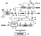
図1は本発明に係る洗浄システム100を表すブロック図である。本図に示すように、洗浄システム100は洗浄装置10、流体貯留槽30、待機循環系44、洗浄流体循環路51(供給路46、還流路47)、回収路80、リンス流体供給系54、乾燥流体供給系58等から構成される。
【0009】
洗浄装置10は、半導体ウエハW(以下、「ウエハW」という)等の洗浄対象を内部に保持し、洗浄流体32等による洗浄を行う装置である。流体貯留槽30は、ウエハWを洗浄するための洗浄流体32を貯留する貯留槽である。待機循環系44は、流体貯留槽30内の洗浄流体32を一定状態に保つために洗浄流体32を循環させる循環路である。供給路46および還流路47はそれぞれ、流体貯留槽30から洗浄装置10に洗浄流体32を供給、還流する供給路および還流路であり、併せて洗浄流体循環路51を構成する。回収路80は、洗浄装置10内の洗浄流体32を流体貯留槽30に回収するための回収路である。リンス流体供給系54は、洗浄装置10にウエハWをリンス処理するためのリンス流体を供給する供給路である。乾燥流体供給系58は、洗浄装置10に乾燥流体を供給する供給路である。
【0010】
なお、ここでいう洗浄処理は、洗浄対象から汚染物質を除去する処理一般をいい、例えば、ウエハWにドライエッチングを施した後、またはドライエッチング後さらにアッシングを施した後に、不要となるマスクであるレジストやエッチング残滓を除去するのに用いることができる。また、ウエハ膜付け処理の前等に行なわれる通常の前洗浄処理等にも用いることができる。
【0011】
洗浄流体32としては、酸化剤、キレート剤およびフッ素化合物、必要に応じて有機溶剤を含有する洗浄剤を用いる。例えば、アンモニア(NH3)と過酸化水素水(H2O2)の混合物、或いは塩化水素(HCl)と過酸化水素水との混合物を用いることができ、レジスト除去には例えば濃硫酸と過酸化水素水との混合物を用いることができる。他に、希フッ酸(HF,H2O)、バッファードフッ酸(HF,NH4F,H2O)、硫酸過水(H2SO4,H2O3,H2O)や、CO2などの超臨界流体等も用いることができる。洗浄後のリンス流体として、例えば、超純水を用いることができる。
【0012】
以下に、洗浄システム100を洗浄装置10等に区分して詳細に説明する。
A.洗浄装置10
図2、3はそれぞれ、洗浄装置10を表す正面図、および側断面図である。
洗浄装置10は、洗浄処理容器12と、洗浄処理容器12の両端に接続された導入部14および排出部16を有する。導入部14には、バッファ部18が接続されている。バッファ部18には1本の配管が分岐した導入配管20が、導入配管20には流体配管26が接続されている。流体配管26および排出部16はそれぞれ供給路46および還流路47に接続されている。
ここで、洗浄処理容器12、導入部14および排出部16、ならびに、バッファ部18および導入配管20は、例えば、ステンレス、あるいはテフロン(ポリ四ふっ化エチレンの登録商標)材料により形成されている。
【0013】
洗浄装置10は、縦型であり、導入部14より導入された洗浄流体32が洗浄装置10の内部を上向きに流れ、排出部16より流出するように構成されている。洗浄装置10は、大気への開放箇所を有しない密閉系に構成されている。
なお、例えば、超臨界条件で洗浄する等の場合には、洗浄装置10を横置き形として、洗浄流体32を横方向に流通させてもよい。
【0014】
洗浄処理容器12は、図3中X方向の厚みT1、言いかえれば、2つの主面12a、12bの間の間隙の薄い扁平な直方体状に形成されている。
洗浄処理容器12の寸法は、洗浄されるウエハWの寸法に応じて設定される。例えば、洗浄されるウエハWの寸法(径)が8インチ(200mm)のとき、洗浄処理容器12は、その内部空間Sの寸法(以下、各部材について、内部空間寸法を単に寸法という。)として、厚みT1が、例えば、5mm程度、長さL1および幅W1がそれぞれ、例えば、230mm程度に形成される。
【0015】
ここで、上記した厚みT1は、搬送および処理中に自重でウエハWが撓む等して主面12a、12bに当たらない程度、また、ウエハWの両面に洗浄流体32を流すのに必要な程度の寸法であり、具体的には、ウエハWの厚みの3倍程度以下に設定することができる。
但し、厚みT1は、これに限定することなく、ウエハWの厚みの略1.5〜300倍程度とすることができる。言いかえれば、洗浄流体32の流れ方向に対して直角に切断したときの洗浄処理容器12の内部断面積をウエハWの直径位置における断面積の1.5〜300倍程度とすることができる。
【0016】
洗浄処理容器12は、X方向に対向する2つの主面12a、12bのいずれか一方が装置から着脱可能あるいは開閉可能に設けられている(図示せず。)。その結果、図示しないウエハ搬送装置を用いてウエハWを洗浄処理容器12内に搬入することができる。
洗浄処理容器12の主面12bには、ウエハWを保持するための保持具(以下、単に保持具という。)24a〜24cが取り付けられている。
【0017】
また、導入部14側から流入する洗浄流体32をウエハWの表裏それぞれに対応して2つに分割する流体分割部として機能する流体分割板25が設置されている。流体分割板25は、その両側面が洗浄処理容器12の内側壁に固定されている。但し、流体分割板25を主面12bと治具等により接続することによって、流体分割板25を洗浄処理容器12に対して固定しても差し支えない。
流体分割板25は、ウエハWの導入部14側の側部に対応して配置される。流体分割板25は略平板形状であり、その幅が内部空間Sの幅W1にほぼ対応し、かつウエハWと対応する辺がウエハWの外形に対応するように形成されている。流体分割板25は洗浄処理容器12の導入部14側のX方向中央に沿って固定されていることから、導入部14側から流入する洗浄流体32を互いに流速が等しくなるように2つに分割する。分割された洗浄流体32はウエハWの表裏上をそれぞれ流れる。この結果、ウエハWの表裏双方における洗浄の均一性が向上する。
【0018】
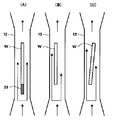
図4は、洗浄装置10内における洗浄流体32の流れを表す断面図である。図4(A)が流体分割板25がある場合で、(B)、(C)が流体分割板25がない場合である。
(A)ではウエハWの手前で流体分割板25により洗浄流体32が流速の等しい2つの洗浄流体32に分離され、そのそれぞれがウエハWの表裏を流れる。このように、洗浄流体32はウエハWの表裏双方で均一な流速で流れていため、ウエハWの表裏双方で洗浄の均一性が確保される。
(B)、(C)は、流体分割板25がなく、かつウエハWがX方向中心からずれた例((B))、あるいは主面12a,12bに対して傾いて設置された例((C))である。その結果、ウエハWの表面上を流れる洗浄流体32の流速が不均一になっている。(B)ではウエハWと主面12a,12b間の距離がウエハWの表裏で異なっていることから、ウエハWの表裏で洗浄流体32の流速が異なっている。(C)ではウエハWと主面12a,12b間の距離が場所によって異なっていることから、ウエハWの場所によって流速が不均一になっている。いずれにしろ、ウエハW上での流速の不均一が生じ、洗浄に不均一性が生じ易くなっている。
ウエハWをその表裏双方が主面12a,12bから等距離になるようにすれば(ウエハWが主面12a,12bの中央に設置すれば)、ウエハWの表面上で洗浄流体32の流速の不均一性は生じにくいが、ウエハWを交換する毎にウエハWを正確に設置するのは必ずしも容易ではない。
【0019】
流体分割板25はウエハWの設置如何に拘わらず常にその表裏が主面12a,12bから等距離になるように設置されており、ウエハWの手前で洗浄流体32がほぼ流速の等しい流体に2分されている。従い、流体分割板25が無いときに比べて、ウエハWの設置状況が洗浄流体32の流速に影響を与えにくくなっている。
以上に示すように、流体分割板25を設置することで、ウエハW上の洗浄流体32の流速分布が均一化され、ウエハWの洗浄の均一性が向上する。
【0020】
導入部14は、図2、3中、下方から上方(Z正方向)に向けて末広がりで、X方向に扁平な形状に形成されている。すなわち、導入部14の入口側(整流側流入口)14aの寸法が、例えば、厚みT2が約10mm程度、幅W2が約160mm程度あるのに対して、長さL2として約70mm程度離間した出口側(整流側出口)14bの寸法が、厚みT3が約5mm程度、幅W3が約230mm程度に形成されている。ここで、入口側14aと出口側14bの流路の断面積は同一寸法に形成されている。また、出口側14bは、厚みT3が洗浄処理容器12の入り口の厚みT1と略同じであり、幅W3が洗浄処理容器12の入り口の幅W1と同じである。
【0021】
バッファ部18は、円柱状であり、直径Dが24mm程度、長さL3が220mm程度に形成されている。バッファ部18の両側には分岐した導入配管20が対向して接続されている。したがって、導入配管20からバッファ部18に2つの流入口18aから水平方向に流入する洗浄流体32は、Y方向中間部で衝突して合流し、流れの方向を上向きに変えて流出口18bから導入部14に流出する。ここで、バッファ部18は、洗浄流体32を所定時間滞留させるだけの、例えば100cm3程度の空間容積を有するとともに、流出口18bの断面積の寸法が2つの流入口18aの断面積の和よりも大きく形成されている。
【0022】
排出部16は、洗浄処理容器12を挟んで導入部14と略対称形状に形成されている。すなわち、排出部16は、流入口(整流側流入口)16aから流出口(整流側流出口)16bに向けて漸次扁平度合いが大きくかつ逆末広がり状に形成されている。
【0023】
B.待機循環系44
待機循環系44は、以下のようにして流体貯留槽30内の洗浄流体32を一定状態に保つための循環を行っている。
【0024】
流体貯留槽30は密閉されて、内部には洗浄流体32が貯留されてN2ガスなどの不活性雰囲気になされている。この洗浄流体32が不足すると、補給系34を介して洗浄流体32補給される。
流体貯留槽30には、循環ポンプ36、洗浄流体32の温度調整を行なう温調器38、洗浄流体32中の不純物を除去するフィルタ40及び開閉弁42を順次介設して再度、流体貯留槽30へ戻る待機循環系44が接続されており、待機中には洗浄流体32を循環させて、温調器38により洗浄流体32の温度を一定に維持しつつフィルタ40により洗浄流体32中の例えば粒状の不純物を除去するようになっている。
【0025】
C.洗浄流体循環路51(供給路46、還流路47)
供給路46、還流路47は、以下のようにして、流体貯留槽30から洗浄装置10への洗浄流体32の供給および還流を行う。
【0026】
待機循環系44と洗浄装置10とを接続して、洗浄流体32を洗浄装置10へ供給するための供給路46が設けられている。供給路46には、流量調整弁48、入口側三方弁50、後述する回収用三方弁82が順に接続されている。
また、洗浄装置10と流体貯留槽30とを接続して、洗浄流体32を流体貯留槽30へ戻すための還流路47が設けられ、出口側三方弁52および排出用三方弁56が接続されている。
【0027】
洗浄装置10は外気から密閉された構造となっているため、供給路46と還流路47により、流体貯留槽30と洗浄装置10の間で洗浄流体32を外気に晒すことなく循環する洗浄流体循環路51が形成されている。
なお、上記供給路46は、待機循環系44に接続せずに、流体貯留槽30と洗浄装置10を直接接続してもよい。
【0028】
D.リンス流体供給系54、回収路80、乾燥流体供給系58
リンス流体供給系54、乾燥流体供給系58、回収路80は、以下のように、洗浄装置10に接続されている。
【0029】
入口側三方弁50には、リンス流体として例えば超純水を外気に晒すことなく供給するためのリンス流体供給系54が接続され、洗浄装置10にリンス流体を供給する。
回収用三方弁82には、洗浄装置10内に残留する洗浄流体32を流体貯留槽30に回収するための回収路80が接続されている。洗浄流体32の回収に際しては、後述する乾燥流体供給系58等により洗浄装置10内に回収用流体(N2ガス等)が供給される。
出口側三方弁52には、N2ガスやアルコールの蒸気などの乾燥流体を外気に晒すことなく供給するための乾燥流体供給系58が接続されている。この乾燥流体供給系58には、その上流側より、流体の流量を調整するレギュレータ60、流体中の不純物を除去するフィルタ62及び開閉弁66により選択的に供給されるアルコールを気化させる気化器64が順次介設されている。
【0030】
リンス流体供給系54及び乾燥流体供給系58を洗浄流体循環路51に接続することによって、洗浄装置10内さらには配管内も同時にリンスして乾燥することができる。
なお、排出用三方弁56には、不用な液体や気体を排出させる排出系68が接続されており、この排出系68には気液分離器70を介設して気体と液体とを分離して、液体をドレインとして系外へ排出するようになっている。
【0031】
E.供給制御部65
これら処理流体、リンス流体、乾燥流体、及び回収用流体を選択的に連続供給するように制御するため、供給制御部65が設けられている。入口側三方弁50、出口側三方弁52等は供給制御部65によって制御される。洗浄流体32は、供給制御部65によって制御可能な入口側三方弁50等を介して流体貯留槽30から流入し流出する。
また、供給制御部65は、出口側三方弁52と共に、洗浄装置10からの流体の流出経路を閉鎖する流出経路閉鎖手段として、ひいては洗浄装置10(洗浄処理容器12)内の流体の圧力を増加させる加圧手段として機能する。また、供給制御部65は回収用三方弁82と相俟って、洗浄装置10(洗浄処理容器12)内の流体の圧力を減少させる減圧手段として機能することもできる。
なお、供給制御部65が循環ポンプ36の出力を制御することで、加圧手段(あるいは減圧手段)として機能しても差し支えない。、
【0032】
(洗浄システム100の動作)
以下に洗浄システム100の動作について説明する。図5は、洗浄システム100の動作手順の1例を示すフロー図である。本図に示すように、洗浄システム100による洗浄手順は、大きくウエハWの搬入(ステップS1)、洗浄処理(ステップS2)、リンス処理(ステップS3)、乾燥処理(ステップS4)、ウエハWの搬出(ステップS5)に区分することができる。
【0033】
洗浄する時の洗浄流体32の温度、言いかえれば、ウエハWの温度は、常温〜80℃程度とし、適宜の手段により所定の温度に保持する。この温度は、エッチングの条件等に応じて適宜選択する。
なお、何ら洗浄処理を行わない待機中のときには、洗浄流体循環路51を閉状態とし、待機循環系44を駆動してこの系内に流体貯留槽30内の洗浄流体32を循環させて、温調器38で洗浄流体32の温度を所定の温度に維持して化学的に安定化させておくと同時に、この洗浄流体32中の不純物をフィルタ40により取り除く。
【0034】
(1)未処理のウエハWを洗浄装置10内へ搬入する(ステップS1)。
具体的には、洗浄処理容器12の主面12aまたは主面12bを開き、図示しないウエハ搬送装置を用いてウエハWを洗浄処理容器12内に搬入する。そして、ウエハWの周縁を保持具24a〜24cで保持して、ウエハWを洗浄処理容器12に固定する。
ウエハWを保持したら、洗浄処理容器12を液密に閉じ、内部空間S内を密閉状態とする。
【0035】
(2)洗浄流体32により洗浄装置10(洗浄処理容器12)内のウエハWを洗浄する(ステップS2)。
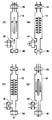
このステップS2は、図5に示すように洗浄流体32の導入(ステップS21)、洗浄流体32の加圧(ステップS22)、洗浄流体32の減圧(ステップS23)、洗浄流体32の排出(ステップS24)の4ステップに区分される。
図6はこれらのステップS21〜S24における洗浄装置10の状態を表す模式図である。ここでは、入口側三方弁50,出口側三方弁52,回収用三方弁82を簡略化して表している。
なお、必要に応じてステップS22,S23の加圧、減圧ステップ、場合によってはステップS21〜S24のステップS2全体が繰り返し行われ、ウエハWの洗浄が確実に行われるようにする。
【0036】
以下ステップS21〜S24の詳細を説明する。
▲1▼洗浄流体32の導入(ステップS21、図6(A))
洗浄流体循環路51の三方弁50、52を、洗浄流体が流れるように開き、流体貯留槽30の洗浄流体32を循環ポンプ36で、例えば、50L/s程度の流量に調整しながら、供給路46を介して洗浄装置10(流体配管26)に送出する。
尚、循環ポンプ36の供給圧は、十分高くなされており、また、必要に応じて待機循環系44の開閉弁42を閉じて供給圧を高めるようにしてもよい。洗浄処理中は、洗浄装置10内を通過した洗浄流体32は、還流路47を通じて流体貯留槽30内へ戻り循環使用される。
【0037】
流体配管26を通った洗浄流体32は、2つの導入配管20に分岐され、バッファ部18の両側の2つの流入口18aからバッファ部18へ流入する。バッファ部18に流入した対向する洗浄流体32の流れは、略中央部で衝突して合流する。これにより、流体配管26を流れる洗浄流体32あるいは2つの2つの導入配管20を流れる洗浄流体32に流速の不均一な分布や乱れを生じていても、バッファ部18でこれらの流速の不均一な分布や乱れが打ち消されて解消する。
バッファ部18に流入した洗浄流体32は、その流れの方向を90°変えて流出口18bから導入部14に流出する。これにより、流速の不均一な分布や乱れはより確実に解消される。
また、洗浄流体32は、バッファ部18で所定の時間滞留し、また、流速を落としてバッファ部18から流出するため、流速の不均一な分布や乱れはより確実に解消される。
【0038】
バッファ部18の流出口18bに接続された入口側14aから導入部14に流入した洗浄流体32は、流速を変えることなく、漸次Y方向の流れの幅を拡大するとともにX方向の流れの厚みを薄くされて出口側14bから洗浄処理容器12内に流出する。これにより、洗浄流体32の流れは一層均一化される。
【0039】
バッファ部18の出口側14bから洗浄処理容器12に流入した洗浄流体32は、ウエハWの両面に沿って上方に流れ、ウエハWに付着等した汚染物質を除去する。この場合、循環ポンプ36で所定の圧力で送出された洗浄流体32は、洗浄処理容器12の狭い厚みT1の部分を通過するため、大きな流速を確保することができる。
【0040】
洗浄処理容器12に流入した洗浄流体32は、ウエハWの表面(表裏面)上を均一でかつ高速で流れる。
ここで、前述のように流体分割板25により洗浄流体32がウエハWの手前でウエハWの表裏に対応した流速のほぼ等しい2つの流体に分岐していることから、ウエハWの表裏の双方における流速の均一性がより確実に確保される。
以上のようにウエハW上での流速の均一性が確保されるため、ウエハWの表面の汚染物質(異物)はまんべんなく除去される
【0041】
洗浄後の洗浄流体32は、洗浄処理容器12から排出部16に流入し、還流路47に流出する。このとき、洗浄処理容器12から排出部16に流入する洗浄流体32の流路は徐々に断面形状を変えるように形成しているため、洗浄流体32の流れに乱れを生じることがなく、したがって、洗浄処理容器12内の洗浄流体32の整流状態を乱すことがない。
【0042】
上記のように構成した洗浄装置10を用いて洗浄流体32やリンス液によりウエハWを洗浄するとき、洗浄処理容器12の厚みT1が薄いため、ウエハWの表面における洗浄流体32等の流速を、例えば、50cm/s程度に設定することができ、この流速は、通常の洗浄装置の、例えば、0.5cm/s程度の値に比べるとはるかに高速である。
また、導入配管20、バッファ部18によって流速を略均一化された洗浄流体32は、導入部14を通過することによってさらに均一な流速に整えられ、ウエハWの幅方向(図1中Y方向)で均一な流速でウエハWの表面を通過する。この流速の均一性は流体分割板25によりさらに確実に担保される。このため、洗浄装置10は、ウエハWの付着物を確実にかつ効率的に除去することができる。
【0043】
▲2▼洗浄流体32の加圧(ステップS22、図6(B))
次に、洗浄装置10(洗浄処理容器12)中の洗浄流体32の圧力を増加させる。この圧力の増加は図6(B)のように出口側三方弁52を閉じて、洗浄装置10と還流路47との接続を解除をすることで行える。
これは、水撃作用またはウォーターハンマーと呼ばれている現象を利用したものであり、以下のように説明できる。
ここでは、入口側三方弁50により洗浄装置10と供給路46が接続され、洗浄処理容器12内を洗浄流体32が流れているときに、出口側三方弁52を閉じている。
出口側三方弁52を閉鎖した瞬間には,出口側三方弁52にごく近接した洗浄流体32は停止するが,少し離れた洗浄流体32は流速をもっている。このため、洗浄装置10内に洗浄流体32がさらに流入しようとすることで、洗浄装置10内の圧力が増大する。
【0044】
詳しくは、以下のように洗浄装置10内に非常に高い圧力と低い圧力が交互に発生し,激しい振動を生ずる。
出口側三方弁52を閉じたことで発生した高圧の状態は圧力波となって入口側へ伝わり,洗浄装置10(洗浄処理容器12)内での洗浄流体32の流速は0となる。圧力波が洗浄装置10の入口側に達すると,この入口付近での圧力が供給路46側より高くなるので,洗浄装置10内から供給路46側へ向かう流れが生じ,洗浄装置10内の圧力は出口側三方弁52を閉鎖する前の状態に戻る。
この状態が今度は反射波として出口側へ伝わり,出口側三方弁52のところでは洗浄流体32を弁から引き離そうとするから低圧を生じ流速は0となる。この状態が再び洗浄装置10内を入口側へ伝わる。このようにして洗浄装置10(洗浄処理容器12)内に大きな圧力変動が生ずる。
【0045】
以上のようにして、出口側三方弁52を閉じることで、洗浄装置10内の圧力を増大できる。この圧力増大は、このような弁の閉鎖以外にも、例えば循環ポンプ36の出力を増大することでも行うことができる。
【0046】
▲3▼洗浄流体32の減圧(ステップS23、図6(C))
入口側三方弁50を閉じて回収用三方弁82を開く。この結果、供給路46から洗浄装置10への洗浄流体32の流れが停止され、洗浄装置10から回収路80を経由して流体貯留槽30へと洗浄流体32が流れる。このため、洗浄装置10内の圧力が低下する。
この圧力低下はこのような洗浄装置10と流体貯留槽30との圧力差を利用した自然減による他、循環ポンプ36等を用いて洗浄装置10内を強制的に減圧しても差し支えない。
また、入口側三方弁50を開いた状態を継続することでも洗浄装置10内の圧力はある程度減少する(圧力変動(振動)は次第に減衰する)。但し、この場合には、循環ポンプ36による洗浄流体32の供給が継続するため、この供給力に起因する圧力増加分は残る。加圧と減圧の圧力差を大きくするためには(後述するように、この圧力差が大きい方が洗浄力が大きいと考えられる)、前述のように回収用三方弁82を開くかまたは循環ポンプ36等を用いて洗浄装置10内を減圧するのが好ましい。
【0047】
▲4▼以上の加圧、減圧の組み合わせにより、ウエハWの効果的な洗浄が行われる。場合により以上の加圧と減圧とを繰り返すことで、ウエハWをさらに洗浄することもできる。
この加圧と減圧の組み合わせは、一般的な洗浄においても有効であるが、特に微細な孔が形成された多孔質材料(例えば、ポーラス材料)の洗浄に効果がある。
ポーラス材料は、ゾル−ゲル法、シルク法、スピードフィルム法、フォックス法等の手法を用いて形成できる。例えば、ゾル−ゲル法ではTEOS(テトラエトキシシラン)のコロイドを有機溶媒に分散させた塗布液を基板に塗布し、その塗布液をゲル化させた後、塗布膜中の溶媒を他の溶媒に置き換え、さらに乾燥させてポーラス材料を形成できる。
【0048】
多孔質材料はその孔中の洗浄が困難である。例えば、ポーラス材料をエッチングしたエッチングガスに含まれる弗素が、孔中に残留しやすい。洗浄流体32の圧力を増大することで、このような多孔質材料の洗浄が効率よく行えるようになる。
【0049】
図7は多孔質材料を加圧と減圧の組み合わせを用いて洗浄する場合を表す模式図である。図7(A)が洗浄前のポーラス材料90の断面を表している。ポーラス材料90はポーラス92が存在することから、その内部の汚染物質95を除去しにくい。ここでは、汚染物質95としてエッチングに用いた弗素(F)が残留しているものとする。
【0050】
洗浄の際に加圧を行うことで洗浄流体32がポーラス材料90内により浸透する(図7(B))。
その後減圧することで、ポーラス材料90に浸透した洗浄流体32がポーラス材料90から出てくる(図7(C))。このとき洗浄流体32と共にポーラス材料90内の汚染物質95(弗素)が取り除かれる。
【0051】
この加圧、減圧による洗浄流体32の洗浄対象内への浸透、取出しによる洗浄効果は多孔質材料等の何らかの意味で洗浄流体32が浸透しうる材料一般に対して有効である。さらに、洗浄流体32が浸透することのない材料であってもその表面に存在する汚染物質に対して一種の揺さぶりをかけることになるので、洗浄効果の向上に結びつく。
【0052】
▲5▼洗浄流体32の排出(ステップS24、図6(D))
洗浄処理が完了したら、洗浄流体32の供給を停止して、出口側三方弁52を乾燥流体供給系58に接続し、回収用流体としてN2ガス等の乾燥流体を流す。これにより内部空間Sや配管類に溜っている洗浄流体32を追い出して、回収路80を経由してこれを流体貯留槽30に回収する。この回収を行なうことにより洗浄流体32の使用量がより低減できる。なお、洗浄流体32の回収は、別に設けた回収用流体供給系を用いて行ってもよい。
なお、既述のように、以上のステップS21〜S24は必要に応じて繰り返される。
【0053】
(3)リンス流体により洗浄装置10内のウエハWを洗浄する(ステップS3)。即ち、内部空間Sに超純水などのリンス流体を流すことによりウエハ表面に付着している洗浄流体32を洗い流してリンスを行なう。
具体的には、入口側三方弁50をリンス流通側に切り替えると同時に、排出用三方弁52を排出側に切り替える。洗浄装置10に例えば超純水よりなるリンス流体を供給し、ウエハ表面等に付着している洗浄流体を洗い流す。この洗い流したリンス流体は、排出系68を通じて気液分離器70内に流入し、ここで液体とガスとに気水分離された後、系外へ排出される。
【0054】
このステップS3は、ステップS2と同様に、リンス流体の導入(ステップS31)、リンス流体の加圧(ステップS32)、リンス流体の減圧(ステップS33)、リンス流体の排出(ステップS34)の4ステップに区分できる。
リンス流体の加圧、減圧によってウエハWの洗浄効率を向上できる。また、ステップS34におけるリンス流体の排出により、この後のステップS4におけるリンス流体の乾燥処理をより効率的に行なうことができる。リンス流体の排出は排出用流体(例えば、N2)を洗浄装置10内に導入することによって行われ、この排出用流体は、乾燥流体や回収用流体を流用してもよいし、別に排出用流体供給系を設けて供給を行なってもよい。
【0055】
これらのステップS31〜S34は、ステップS21〜S24と流体の種類が異なるものの本質的に相違するわけではないので、詳細な説明は省略する。
なお、ステップS32〜S33の加圧、減圧を省略して、通常のリンス処理のみを行っても差し支えない。
なお、必要に応じてステップS32,S33の加圧、減圧ステップ、場合によってはステップS31〜S34のステップS3全体が繰り返し行われ、ウエハWのリンス処理が確実に行われるようにする。
【0056】
(4)洗浄装置10内のウエハWを乾燥する(ステップS4)。
▲1▼例えば、洗浄装置10内にイソプロピルアルコール(IPA)等の蒸気アルコールを流す。具体的には、N2ガスを供給した状態で、開閉弁66を開にすることにより、アルコールを気化器64内で気化させてN2ガス中に混入させる。
これにより、気化アルコールが洗浄装置10内に供給されて、内部に付着するリンス流体の表面張力が破られて液滴ができ難い状態となり、乾燥し易くなる。
【0057】
▲2▼更に、N2ガス等を流すことにより、ウエハW面及び洗浄処理容器12内を完全に乾燥させる。即ち、気化アルコールの供給を停止し、N2ガスのみを流し続けてウエハ面及び洗浄装置10内の乾燥を行なう。
この場合、N2ガスを加熱してホットN2ガスとして流すことにより、乾燥処理時間を短縮することができる。
【0058】
▲3▼乾燥処理の手法としては、マランゴニー(Marangoni)乾燥処理によってもよく、あるいはIPA蒸気を流す乾燥処理によってもよく、あるいは減圧乾燥処理によってもよい。上記▲1▼、▲2▼の説明は、マランゴニー乾燥処理に対応する説明である。以下、これらの乾燥処理につき詳しく説明する。
1)マランゴニー乾燥処理は、N2ガスをキャリアガスとしてチャンバ内にIPA蒸気を供給し、非常にゆっくりとした速度でチャンバ内の水を排液するようにすると水とIPAとの間の表面張力の差に起因して液面降下後にウエハの表面が乾燥されるというものである。ここで、乾燥を完全なものにするために、その後ホットN2ガスを流したり赤外線を照射する。
2)IPA蒸気を流す乾燥処理は、チャンバ内のリンス流体を急速に排液した後に、チャンバ内にN2ガスをキャリアガスとしてIPA蒸気を供給し、チャンバ内の水がIPA蒸気に置換されたタイミングでIPA蒸気の供給をやめ、高温のホットN2ガスを吹き付けるものである。なお、この場合、熱源として赤外線を照射するようにしてもよい。
【0059】
3)減圧乾燥処理は洗浄処理容器12内を減圧することで、ウエハWを乾燥する。この手法は、洗浄処理容器12がウエハの大きさよりわずかに大きい場合に有効であり、乾燥に要する時間を短くでき、これによってウォーターマークの発生が始まる前に水分を飛ばしてしまうことが可能になる。この際に、赤外線を照射して加熱することによりより短時間で乾燥することができる。
なお、乾燥処理においては、マランゴニー乾燥処理と減圧乾燥処理の組合せ、あるいはIPA蒸気を流す乾燥処理と減圧乾燥処理の組合せを行うことによって、より優れた乾燥状態を実現することができる。
【0060】
(5)洗浄処理済のウエハWを洗浄装置10内から搬出する(ステップS5)。
具体的には、洗浄処理容器12の主面12aまたは主面12bを開き、保持具24a〜24cによるウエハWの固定を解除して、図示しないウエハ搬送装置を用いて洗浄処理が施されたウエハWを洗浄処理容器12内から搬出する。
【0061】
以上説明した本実施の形態例に係る基板の洗浄方法および装置は、洗浄流体32またはリンス流体を加圧することで、洗浄の困難な洗浄対象(例えば、多孔質材料)を確実に洗浄することができる。この加圧に際して、洗浄処理容器12内に流体が流入している状態での洗浄処理容器12内からの流体の流出停止が効果的な手法である。
また、ウエハの表裏に対して洗浄流体32を均一で高速に流すことができるため、ウエハを効率的にまた確実に洗浄することができる。
【0062】
(その他の実施形態)
本発明の実施形態は上記実施形態には限られず拡張、変更できる。拡張、変更された実施形態も本発明の技術的範囲に含まれる。
(1)例えば、対象として半導体ウエハ等の基板に限定することなく、ガラス基板等も含めた洗浄対象一般を用いることができる。
(2)また、加圧手段も流体が流入している状態での流体の流出停止に限られず、ポンプ等の流体の供給力の調節によって行っても差し支えない。
(3)さらに、流体分割板25は上記実施形態に示したような洗浄対象の上流側にのみならず、下流側にかけても設置することができる。
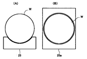
図8は流体分割板の他の形状を上記実施形態と比較して表す正面図である。図8(A)は上記実施形態における流体分割板25であり、図8(B)は他の形状の流体分割板25aを表す。
流体分割板25aはウエハWの全周に対応した開口部を有し、この開口部にウエハWが配置されている。このようにすることで、流体分割板25aにより流体が分割した状態がウエハWの上流、下流の双方で維持され、ウエハW上における流速の均一性、ひいては洗浄の均一性をさらに向上することができる。
【0063】
【発明の効果】
以上説明したように、本発明によれば洗浄対象を効率的に洗浄できる洗浄装置、洗浄方法を提供することができる。
【図面の簡単な説明】
【図1】本発明に係る洗浄システムを表すブロック図である。
【図2】図1に示す洗浄装置を拡大して表す正面図である。
【図3】図1に示す洗浄装置を拡大して表す側断面図である。
【図4】洗浄装置内における流体の流れを表す模式図である。
【図5】本発明に係る洗浄システムによる洗浄の手順を表すフロー図である。
【図6】洗浄工程中における洗浄装置の状態を表す模式図である。
【図7】洗浄工程中における加圧、減圧の作用を表す模式図である。
【図8】流体分割板の例を表す正面図である。
【符号の説明】
100…洗浄システム、 10…洗浄装置、 12…洗浄処理容器、 12a,12b…主面、 14…導入部、 14a…入口側、 14b…出口側、 16…排出部、 18…バッファ部、 18a…流入口、 18b…流出口、 20…導入配管、 24a…保持具、 25…流体分割板、 26…流体配管、 30…流体貯留槽、 32…洗浄流体、 34…補給系、 36…循環ポンプ、 38…温調器、 40…フィルタ、 42…開閉弁、 44…待機循環系、 46…供給路、 47…還流路、 48…流量調整弁、 50…入口側三方弁、 51…洗浄流体循環路、 52…出口側三方弁、 54…リンス流体供給系、 56…排出用三方弁、 58…乾燥流体供給系、 60…レギュレータ、 62…フィルタ、 64…気化器、 65…供給制御部、 66…開閉弁、 68…排出系、 70…気液分離器、 80…回収路、 82…回収用三方弁[0001]
TECHNICAL FIELD OF THE INVENTION
The present invention relates to a cleaning method and a cleaning apparatus for cleaning a substrate or the like.
[0002]
[Prior art]
A cleaning apparatus for cleaning a substrate such as a semiconductor wafer has been used. By holding the substrate in the cleaning chamber and flowing the cleaning fluid at a high speed, contaminants (eg, organic substances, metal impurities, particles, natural oxide films) on the substrate are removed.
[0003]
[Problems to be solved by the invention]
By the way, there are cases where it is difficult to remove contaminants from the substrate. For example, in the case of a substrate containing a porous material, it is difficult to remove the contaminants because the contaminants penetrate into the inside of the substrate through the holes. An example of such a porous material is a porous material formed by applying a solution containing an organic material (for example, TEOS (tetraethoxysilane)) and curing the solution by a sol-gel method or the like. When the porous material is dry-etched or the like, fluorine contained in an etching gas or the like tends to remain in the fine porous material. The remaining fluorine may cause a problem such as voids (voids) in the plating layer when the substrate is plated. Thus, even when it is difficult to remove contaminants, a cleaning apparatus that can effectively remove contaminants is desired.
Further, in the cleaning, uniformity of the cleaning is required. For example, if the flow rate of the cleaning liquid differs depending on the location of the substrate (for example, front and back), unevenness may occur in the cleaning of the substrate and contaminants may not be partially removed. Thus, there is a demand for a cleaning apparatus capable of uniformly cleaning the entire substrate without unevenness.
The present invention has been made to solve such a problem, and an object of the present invention is to provide a cleaning apparatus and a cleaning method capable of efficiently cleaning an object to be cleaned such as a substrate.
[0004]
[Means for Solving the Problems]
(1) In order to achieve the above object, a cleaning method according to the present invention includes a step of introducing a fluid into a cleaning chamber in which a cleaning target including at least a part of a porous material is installed, and a step of introducing a fluid into the cleaning chamber. A pressurizing step of pressurizing the fluid, and a depressurizing step of depressurizing the fluid pressurized in the pressurizing step.
The porous material has difficulty in removing the contaminants because the contaminants penetrate into the porous material through the pores. By increasing and decreasing the pressure of the fluid used for cleaning when cleaning the porous material, contaminants can be efficiently removed. The fluid penetrates the inside of the porous material by pressurizing, and the fluid is returned from the inside of the porous material by depressurizing. Upon depressurization, contaminants are released from the interior of the porous material together with the fluid. As a result, contaminants are effectively removed from the porous material.
The porous material generally includes a material in which a plurality of fine pores (about 0.1 μm or less) are formed. As an example, a solution containing an organic material (for example, TEOS (tetraethoxysilane)) is applied, -Porous materials formed by curing by a gel method or the like. In addition to the sol-gel method, a porous material can be formed by using a method such as a silk method, a speed film method, and a fox method.
In addition, the term "fluid" used herein refers to the purpose of removing the cleaning fluid from the object to be cleaned, in addition to the purpose of removing the contaminant itself from the object to be cleaned. In the present invention, the term “fluid” is to be interpreted as such.
[0005]
(2) The cleaning method according to the present invention includes an inflow / outflow step of causing a fluid to flow into a cleaning chamber through a first path and flowing out the fluid through a second path, and the cleaning chamber through the first path. Pressurizing the fluid in the cleaning chamber by stopping the outflow of the fluid from the cleaning chamber through the second path while the fluid is flowing into the cleaning chamber. Characteristic cleaning method.
By stopping the outflow of the fluid from the cleaning chamber while the fluid is flowing into the cleaning chamber, it is possible to cause a rapid pressure fluctuation in the cleaning chamber. The object to be cleaned can be effectively cleaned by the rapid pressure change.
[0006]
(3) The cleaning apparatus according to the present invention includes a cleaning chamber for installing a cleaning target, an inflow path for flowing a fluid into the cleaning chamber, an outflow path for flowing a fluid from the cleaning chamber, and the inflow path to the cleaning chamber. Outflow path closing means for closing the outflow path when the fluid flows in from the path and the fluid flows out from the outflow path.
By using the outflow path closing means, when the fluid flows into the cleaning chamber from the inflow path and the fluid flows out of the outflow path, the outflow path is closed to stop the outflow of the fluid, so that the abrupt flow into the cleaning chamber. Pressure fluctuations can occur. The object to be cleaned can be effectively cleaned by the rapid pressure change.
[0007]
(4) The cleaning device according to the present invention includes two opposing surfaces through which a fluid flows, a substrate holding unit that holds the substrate between the two surfaces, and the fluid of the substrate held by the substrate holding unit. And a fluid dividing portion that is provided near the side portion on which the fluid flows in, and divides the fluid that flows in so as to correspond to the front and back of the substrate.
On the upstream side of the substrate, there is provided a fluid dividing portion for dividing the fluid flowing in so as to correspond to the front and back of the substrate. Since the front and back surfaces of the substrate are each washed with the fluid divided in advance, the uniformity of the cleaning of the substrate can be improved.
[0008]
BEST MODE FOR CARRYING OUT THE INVENTION
(1st Embodiment)
Hereinafter, embodiments of the present invention will be described in detail with reference to the drawings.
FIG. 1 is a block diagram showing a
[0009]
The
[0010]
Note that the cleaning process referred to here generally refers to a process for removing contaminants from a cleaning target. For example, after performing dry etching on the wafer W, or after further performing ashing after dry etching, an unnecessary mask is used. It can be used to remove certain resists and etching residues. Further, it can also be used for a normal pre-cleaning process performed before the wafer film forming process or the like.
[0011]
As the cleaning
[0012]
Hereinafter, the
2 and 3 are a front view and a side sectional view, respectively, illustrating the
The
Here, the cleaning
[0013]
The
In addition, for example, in the case of cleaning under supercritical conditions, the
[0014]
The cleaning
The dimensions of the
[0015]
Here, the above-mentioned thickness T1 is such that the wafer W is bent under its own weight during transportation and processing so that it does not hit the
However, the thickness T1 is not limited to this, and can be approximately 1.5 to 300 times the thickness of the wafer W. In other words, the internal cross-sectional area of the cleaning
[0016]
The cleaning
Holders (hereinafter simply referred to as “holders”) 24 a to 24 c for holding the wafer W are attached to the
[0017]
In addition, a
The
[0018]
FIG. 4 is a cross-sectional view illustrating a flow of the cleaning
In (A), the cleaning
(B) and (C) show an example in which the
If the front and back surfaces of the wafer W are set at the same distance from the
[0019]
The
As described above, by disposing the
[0020]
2 and 3, the
[0021]
The
[0022]
The
[0023]
B.
The
[0024]
The
The
[0025]
C. Cleaning fluid circulation path 51 (
The
[0026]
A
Further, a
[0027]
Since the
The
[0028]
D. Rinse
The rinsing
[0029]
A rinsing
The recovery three-
The outlet side three-
[0030]
By connecting the rinsing
The discharge three-
[0031]
E. FIG. Supply control unit 65
A supply control unit 65 is provided for controlling the processing fluid, the rinsing fluid, the drying fluid, and the recovery fluid to be selectively and continuously supplied. The inlet three-
In addition, the supply control unit 65, together with the outlet side three-
Note that the supply control unit 65 may function as a pressurizing unit (or a depressurizing unit) by controlling the output of the
[0032]
(Operation of the cleaning system 100)
Hereinafter, the operation of the
[0033]
The temperature of the cleaning
During a standby state in which no cleaning process is performed, the cleaning
[0034]
(1) An unprocessed wafer W is loaded into the cleaning apparatus 10 (Step S1).
Specifically, the
After holding the wafer W, the cleaning
[0035]
(2) The wafer W in the cleaning apparatus 10 (cleaning processing container 12) is cleaned by the cleaning fluid 32 (Step S2).
In step S2, as shown in FIG. 5, the cleaning
FIG. 6 is a schematic diagram showing the state of the
The pressurizing and depressurizing steps of steps S22 and S23, and in some cases, the entire step S2 of steps S21 to S24 are repeatedly performed as necessary, so that the wafer W is reliably cleaned.
[0036]
Hereinafter, steps S21 to S24 will be described in detail.
(1) Introduction of the cleaning fluid 32 (step S21, FIG. 6A)
The three-
The supply pressure of the
[0037]
The cleaning
The cleaning
Further, the cleaning
[0038]
The cleaning
[0039]
The cleaning
[0040]
The cleaning
Here, as described above, the cleaning
As described above, since the uniformity of the flow velocity on the wafer W is ensured, contaminants (foreign matter) on the surface of the wafer W are evenly removed.
[0041]
The cleaning
[0042]
When cleaning the wafer W with the cleaning
The cleaning
[0043]
(2) Pressurization of the cleaning fluid 32 (Step S22, FIG. 6B)
Next, the pressure of the cleaning
This utilizes a phenomenon called water hammer or water hammer, and can be explained as follows.
Here, the
At the moment when the outlet three-
[0044]
More specifically, a very high pressure and a very low pressure are alternately generated in the
The state of high pressure generated by closing the outlet three-
This state is transmitted to the outlet side as a reflected wave, and at the outlet side three-
[0045]
As described above, by closing the outlet three-
[0046]
(3) Decompression of the cleaning fluid 32 (step S23, FIG. 6C)
The inlet side three-
This pressure drop may be caused not only by a natural decrease utilizing the pressure difference between the cleaning
Further, the pressure in the
[0047]
{Circle around (4)} By the combination of the above-described pressurization and decompression, the wafer W is effectively cleaned. In some cases, the wafer W can be further cleaned by repeating the above pressurization and decompression.
This combination of pressurization and decompression is effective in general cleaning, but is particularly effective in cleaning a porous material (for example, a porous material) in which fine pores are formed.
The porous material can be formed by using a sol-gel method, a silk method, a speed film method, a Fox method, or the like. For example, in the sol-gel method, a coating solution in which a colloid of TEOS (tetraethoxysilane) is dispersed in an organic solvent is applied to a substrate, and after the coating solution is gelled, the solvent in the coating film is replaced with another solvent. It can be replaced and further dried to form a porous material.
[0048]
Porous materials are difficult to clean in their pores. For example, fluorine contained in an etching gas obtained by etching a porous material easily remains in the holes. By increasing the pressure of the cleaning
[0049]
FIG. 7 is a schematic diagram illustrating a case where a porous material is washed using a combination of pressurization and decompression. FIG. 7A shows a cross section of the
[0050]
By applying pressure at the time of cleaning, the cleaning
Thereafter, by reducing the pressure, the cleaning
[0051]
The permeation and removal of the cleaning
[0052]
(5) Discharge of the cleaning fluid 32 (Step S24, FIG. 6 (D))
When the cleaning process is completed, the supply of the cleaning
Note that, as described above, the above steps S21 to S24 are repeated as necessary.
[0053]
(3) The wafer W in the
Specifically, the three-
[0054]
As in step S2, this step S3 includes four steps: introduction of a rinsing fluid (step S31), pressurization of the rinsing fluid (step S32), depressurization of the rinsing fluid (step S33), and discharge of the rinsing fluid (step S34). Can be divided into
The cleaning efficiency of the wafer W can be improved by pressurizing and depressurizing the rinsing fluid. Further, the rinsing fluid is discharged in step S34, so that the rinsing fluid can be more efficiently dried in step S4. The discharge of the rinsing fluid is performed by a discharge fluid (eg, N 2 ) Is introduced into the
[0055]
These steps S31 to S34 are different from the steps S21 to S24 in the type of fluid, but are not essentially different from each other.
Note that it is possible to omit the pressurizing and depressurizing steps S32 to S33 and perform only the normal rinsing process.
In addition, if necessary, the pressurizing and depressurizing steps of steps S32 and S33, and in some cases, the entire step S3 of steps S31 to S34 are repeatedly performed, so that the rinsing process of the wafer W is reliably performed.
[0056]
(4) The wafer W in the
{Circle around (1)} For example, steam alcohol such as isopropyl alcohol (IPA) is flowed into the
As a result, the vaporized alcohol is supplied into the
[0057]
(2) N 2 By flowing gas or the like, the surface of the wafer W and the inside of the
In this case, N 2 Heat the gas to get hot N 2 By flowing the gas, the drying time can be shortened.
[0058]
{Circle around (3)} As a method of the drying treatment, a Marangoni drying treatment, a drying treatment in which IPA vapor is passed, or a reduced-pressure drying treatment may be used. The description of (1) and (2) above corresponds to the Marangoni drying process. Hereinafter, these drying processes will be described in detail.
1) Marangoni drying process is N 2 When IPA vapor is supplied into the chamber using the gas as a carrier gas and the water in the chamber is drained at a very slow speed, the liquid level drops due to the difference in surface tension between the water and the IPA. Later, the surface of the wafer is dried. Here, to complete the drying, hot N 2 Flow gas or irradiate infrared rays.
2) In the drying process of flowing IPA vapor, the rinse fluid in the chamber is rapidly drained, and then N 2 The IPA vapor is supplied using the gas as a carrier gas, and the supply of the IPA vapor is stopped at the timing when the water in the chamber is replaced with the IPA vapor. 2 It blows gas. In this case, infrared rays may be irradiated as a heat source.
[0059]
3) In the reduced pressure drying process, the wafer W is dried by reducing the pressure in the
In the drying treatment, a more excellent drying state can be realized by performing a combination of a Marangoni drying treatment and a reduced-pressure drying treatment or a combination of a drying treatment in which IPA vapor is passed and a reduced-pressure drying treatment.
[0060]
(5) The cleaning-processed wafer W is unloaded from the cleaning apparatus 10 (Step S5).
Specifically, the
[0061]
The substrate cleaning method and apparatus according to the present embodiment described above can reliably clean a cleaning target (for example, a porous material) that is difficult to clean by pressurizing the cleaning
Further, since the cleaning
[0062]
(Other embodiments)
The embodiment of the present invention is not limited to the above embodiment, and can be extended and changed. Extended and modified embodiments are also included in the technical scope of the present invention.
(1) For example, the object to be cleaned is not limited to a substrate such as a semiconductor wafer, but may be a general cleaning object including a glass substrate.
(2) Further, the pressurizing means is not limited to stopping the outflow of the fluid while the fluid is flowing therein, but may be performed by adjusting the supply force of the fluid such as a pump.
(3) Further, the
FIG. 8 is a front view showing another shape of the fluid dividing plate in comparison with the above embodiment. FIG. 8A shows the
The
[0063]
【The invention's effect】
As described above, according to the present invention, it is possible to provide a cleaning apparatus and a cleaning method capable of efficiently cleaning a cleaning target.
[Brief description of the drawings]
FIG. 1 is a block diagram illustrating a cleaning system according to the present invention.
FIG. 2 is an enlarged front view of the cleaning device shown in FIG.
FIG. 3 is an enlarged side sectional view of the cleaning device shown in FIG. 1;
FIG. 4 is a schematic diagram illustrating a flow of a fluid in the cleaning device.
FIG. 5 is a flowchart showing a procedure of cleaning by the cleaning system according to the present invention.
FIG. 6 is a schematic diagram illustrating a state of a cleaning apparatus during a cleaning process.
FIG. 7 is a schematic diagram showing the effects of pressurization and decompression during a cleaning step.
FIG. 8 is a front view illustrating an example of a fluid dividing plate.
[Explanation of symbols]
DESCRIPTION OF
Claims (10)
前記洗浄室内に導入された前記流体を加圧する加圧ステップと、
前記加圧ステップで加圧された前記流体を減圧する減圧ステップと、
を具備することを特徴とする洗浄方法。An introduction step of introducing a fluid into a cleaning chamber in which a cleaning target including at least a part of a porous material is installed,
A pressurizing step of pressurizing the fluid introduced into the cleaning chamber,
A decompression step of decompressing the fluid pressurized in the pressurization step,
A cleaning method, comprising:
ことを特徴とする請求項1記載の洗浄方法。The cleaning method according to claim 1, wherein the pressurizing step includes a step of increasing a supply power for supplying a fluid into the cleaning chamber.
前記加圧ステップが、前記第1の経路を通じた洗浄室内への流体の流入が行われている状態で、前記第2の経路を閉鎖して該洗浄室からの流体の流出を停止するステップを含む
ことを特徴とする請求項1記載の洗浄方法。The introduction step includes a step of flowing fluid out of the cleaning chamber through a second path while flowing fluid into the cleaning chamber through a first path,
The step of closing includes closing the second path and stopping the flow of the fluid from the cleaning chamber while the fluid is flowing into the cleaning chamber through the first path. The cleaning method according to claim 1, further comprising:
ことを特徴とする請求項1記載の洗浄方法。The cleaning method according to claim 1, wherein the depressurizing step includes a step of reducing a supply power for supplying a fluid into the cleaning chamber.
ことを特徴とする請求項1記載の洗浄方法。2. The cleaning method according to claim 1, wherein the depressurizing step includes a step of discharging a part of the pressurized fluid from the cleaning chamber.
前記第1の経路を通じて前記洗浄室内に流体が流入している状態で前記第2の経路を通じた該洗浄室内からの流体の流出を停止することによって、該洗浄室内における流体の圧力を増加する加圧工程と、
を具備することを特徴とする洗浄方法。An inflow / outflow step of causing a fluid to flow into the cleaning chamber through a first path and flowing out the fluid through a second path;
By stopping the outflow of fluid from the cleaning chamber through the second path while the fluid is flowing into the cleaning chamber through the first path, the pressure of the fluid in the cleaning chamber is increased. Pressure process;
A cleaning method, comprising:
前記洗浄室内から加圧された流体の一部を流出させて流体を減圧する減圧工程をさらに具備することを特徴とする請求項7記載の洗浄方法。After the pressing step,
The cleaning method according to claim 7, further comprising a decompression step of discharging a part of the pressurized fluid from the cleaning chamber to decompress the fluid.
前記洗浄室内に流体を流入させる流入経路と、
前記洗浄室内から流体を流出させる流出経路と、
前記洗浄室内に前記流入経路から流体を流入し、かつ前記流出経路から流体が流出した状態において、前記流出経路を閉鎖する流出経路閉鎖手段と、
を具備することを特徴とする洗浄装置。A washing room for installing a washing object,
An inflow path through which a fluid flows into the cleaning chamber;
An outflow path for allowing the fluid to flow out of the cleaning chamber;
Outflow path closing means for closing the outflow path in a state where the fluid flows into the cleaning chamber from the inflow path and the fluid flows out of the outflow path,
A cleaning device comprising:
前記2つの面の間に基板を保持する基板保持部と、
前記基板保持部に保持された基板の前記流体が流入する側の側部に近接して設けられ、かつ該流入する流体を前記基板の表裏に対応するように分割する流体分割部と、
を具備することを特徴とする洗浄装置。Two opposing surfaces through which the fluid flows,
A substrate holding unit that holds a substrate between the two surfaces;
A fluid dividing unit that is provided adjacent to a side of the substrate held by the substrate holding unit on which the fluid flows, and divides the flowing fluid so as to correspond to the front and back of the substrate,
A cleaning device comprising:
Priority Applications (1)
| Application Number | Priority Date | Filing Date | Title |
|---|---|---|---|
| JP2002163367A JP4037179B2 (en) | 2002-06-04 | 2002-06-04 | Cleaning method, cleaning device |
Applications Claiming Priority (1)
| Application Number | Priority Date | Filing Date | Title |
|---|---|---|---|
| JP2002163367A JP4037179B2 (en) | 2002-06-04 | 2002-06-04 | Cleaning method, cleaning device |
Publications (2)
| Publication Number | Publication Date |
|---|---|
| JP2004014642A true JP2004014642A (en) | 2004-01-15 |
| JP4037179B2 JP4037179B2 (en) | 2008-01-23 |
Family
ID=30431870
Family Applications (1)
| Application Number | Title | Priority Date | Filing Date |
|---|---|---|---|
| JP2002163367A Expired - Fee Related JP4037179B2 (en) | 2002-06-04 | 2002-06-04 | Cleaning method, cleaning device |
Country Status (1)
| Country | Link |
|---|---|
| JP (1) | JP4037179B2 (en) |
Cited By (14)
| Publication number | Priority date | Publication date | Assignee | Title |
|---|---|---|---|---|
| JP2007234813A (en) * | 2006-02-28 | 2007-09-13 | Dainippon Screen Mfg Co Ltd | Method and device for processing substrate |
| WO2010018825A1 (en) * | 2008-08-11 | 2010-02-18 | 株式会社ニコン | Light exposure device, maintenance method, and device manufacturing method |
| JP2010148632A (en) * | 2008-12-25 | 2010-07-08 | Sharp Corp | Cleaning apparatus |
| JP2012046809A (en) * | 2010-08-30 | 2012-03-08 | Shiga Yamashita:Kk | Draining device for workpiece |
| US20130271945A1 (en) | 2004-02-06 | 2013-10-17 | Nikon Corporation | Polarization-modulating element, illumination optical apparatus, exposure apparatus, and exposure method |
| US9341954B2 (en) | 2007-10-24 | 2016-05-17 | Nikon Corporation | Optical unit, illumination optical apparatus, exposure apparatus, and device manufacturing method |
| US9423698B2 (en) | 2003-10-28 | 2016-08-23 | Nikon Corporation | Illumination optical apparatus and projection exposure apparatus |
| US9678437B2 (en) | 2003-04-09 | 2017-06-13 | Nikon Corporation | Illumination optical apparatus having distribution changing member to change light amount and polarization member to set polarization in circumference direction |
| US9678332B2 (en) | 2007-11-06 | 2017-06-13 | Nikon Corporation | Illumination apparatus, illumination method, exposure apparatus, and device manufacturing method |
| US9844794B2 (en) | 2013-04-23 | 2017-12-19 | Ebara Corporation | Substrate plating apparatus and substrate plating method |
| US9885872B2 (en) | 2003-11-20 | 2018-02-06 | Nikon Corporation | Illumination optical apparatus, exposure apparatus, and exposure method with optical integrator and polarization member that changes polarization state of light |
| US9891539B2 (en) | 2005-05-12 | 2018-02-13 | Nikon Corporation | Projection optical system, exposure apparatus, and exposure method |
| US10101666B2 (en) | 2007-10-12 | 2018-10-16 | Nikon Corporation | Illumination optical apparatus, exposure apparatus, and device manufacturing method |
| CN113019471A (en) * | 2021-02-07 | 2021-06-25 | 铜仁市诚一环保科技有限公司 | Cleaning method and equipment for denitration catalyst |
-
2002
- 2002-06-04 JP JP2002163367A patent/JP4037179B2/en not_active Expired - Fee Related
Cited By (22)
| Publication number | Priority date | Publication date | Assignee | Title |
|---|---|---|---|---|
| US9678437B2 (en) | 2003-04-09 | 2017-06-13 | Nikon Corporation | Illumination optical apparatus having distribution changing member to change light amount and polarization member to set polarization in circumference direction |
| US9885959B2 (en) | 2003-04-09 | 2018-02-06 | Nikon Corporation | Illumination optical apparatus having deflecting member, lens, polarization member to set polarization in circumference direction, and optical integrator |
| US9760014B2 (en) | 2003-10-28 | 2017-09-12 | Nikon Corporation | Illumination optical apparatus and projection exposure apparatus |
| US9423698B2 (en) | 2003-10-28 | 2016-08-23 | Nikon Corporation | Illumination optical apparatus and projection exposure apparatus |
| US9885872B2 (en) | 2003-11-20 | 2018-02-06 | Nikon Corporation | Illumination optical apparatus, exposure apparatus, and exposure method with optical integrator and polarization member that changes polarization state of light |
| US10281632B2 (en) | 2003-11-20 | 2019-05-07 | Nikon Corporation | Illumination optical apparatus, exposure apparatus, and exposure method with optical member with optical rotatory power to rotate linear polarization direction |
| US10234770B2 (en) | 2004-02-06 | 2019-03-19 | Nikon Corporation | Polarization-modulating element, illumination optical apparatus, exposure apparatus, and exposure method |
| US20130271945A1 (en) | 2004-02-06 | 2013-10-17 | Nikon Corporation | Polarization-modulating element, illumination optical apparatus, exposure apparatus, and exposure method |
| US10241417B2 (en) | 2004-02-06 | 2019-03-26 | Nikon Corporation | Polarization-modulating element, illumination optical apparatus, exposure apparatus, and exposure method |
| US10007194B2 (en) | 2004-02-06 | 2018-06-26 | Nikon Corporation | Polarization-modulating element, illumination optical apparatus, exposure apparatus, and exposure method |
| US9891539B2 (en) | 2005-05-12 | 2018-02-13 | Nikon Corporation | Projection optical system, exposure apparatus, and exposure method |
| JP2007234813A (en) * | 2006-02-28 | 2007-09-13 | Dainippon Screen Mfg Co Ltd | Method and device for processing substrate |
| US10101666B2 (en) | 2007-10-12 | 2018-10-16 | Nikon Corporation | Illumination optical apparatus, exposure apparatus, and device manufacturing method |
| US9341954B2 (en) | 2007-10-24 | 2016-05-17 | Nikon Corporation | Optical unit, illumination optical apparatus, exposure apparatus, and device manufacturing method |
| US9857599B2 (en) | 2007-10-24 | 2018-01-02 | Nikon Corporation | Optical unit, illumination optical apparatus, exposure apparatus, and device manufacturing method |
| US9678332B2 (en) | 2007-11-06 | 2017-06-13 | Nikon Corporation | Illumination apparatus, illumination method, exposure apparatus, and device manufacturing method |
| WO2010018825A1 (en) * | 2008-08-11 | 2010-02-18 | 株式会社ニコン | Light exposure device, maintenance method, and device manufacturing method |
| JP2010148632A (en) * | 2008-12-25 | 2010-07-08 | Sharp Corp | Cleaning apparatus |
| JP2012046809A (en) * | 2010-08-30 | 2012-03-08 | Shiga Yamashita:Kk | Draining device for workpiece |
| US9844794B2 (en) | 2013-04-23 | 2017-12-19 | Ebara Corporation | Substrate plating apparatus and substrate plating method |
| CN113019471A (en) * | 2021-02-07 | 2021-06-25 | 铜仁市诚一环保科技有限公司 | Cleaning method and equipment for denitration catalyst |
| CN113019471B (en) * | 2021-02-07 | 2023-05-23 | 铜仁市诚一环保科技有限公司 | Method and equipment for cleaning denitration catalyst |
Also Published As
| Publication number | Publication date |
|---|---|
| JP4037179B2 (en) | 2008-01-23 |
Similar Documents
| Publication | Publication Date | Title |
|---|---|---|
| EP1834708B1 (en) | Substrate cleaning method, substrate cleaning system and program storage medium | |
| JP3502947B2 (en) | Semiconductor ultra-fine particle cleaning equipment | |
| JP4037179B2 (en) | Cleaning method, cleaning device | |
| US6325081B1 (en) | Washing apparatus and washing method | |
| JP3142195B2 (en) | Chemical supply device | |
| JP3177736B2 (en) | Processing equipment | |
| US6478035B1 (en) | Cleaning device, cleaning system, treating device and cleaning method | |
| US6200387B1 (en) | Method and system for processing substrates using nebulized chemicals created by heated chemical gases | |
| JP4608748B2 (en) | Cleaning device, cleaning system and cleaning method | |
| JP2004535662A (en) | Mega-band system | |
| JPH10163153A (en) | Liquid-saving liquid-supply nozzle used for wet treatment including cleaning, etching, development, stripping, etc., as well as apparatus and method for wet treatment | |
| JP7128099B2 (en) | SUBSTRATE PROCESSING APPARATUS AND SUBSTRATE PROCESSING METHOD | |
| CN1965388A (en) | Apparatus and method for drying substrates | |
| EP1848023B1 (en) | Substrate cleaning method, substrate cleaning system and program storage medium | |
| WO1991002601A1 (en) | High frequency sonic substrate processing module | |
| JP4903992B2 (en) | Semiconductor substrate cleaning and drying system and cleaning and drying method using the same | |
| JP2004335675A (en) | Fine structure drying treatment method, its equipment, and its high pressure vessel | |
| JP2006093334A (en) | Substrate processing device | |
| US6045621A (en) | Method for cleaning objects using a fluid charge | |
| US8083857B2 (en) | Substrate cleaning method and substrate cleaning apparatus | |
| KR102149695B1 (en) | Cleaning apparatus for semiconductor components | |
| JP2001271188A (en) | Substrate treatment apparatus | |
| US20020104556A1 (en) | Controlled fluid flow and fluid mix system for treating objects | |
| JP2968779B1 (en) | Plate cleaning equipment | |
| CN114930506A (en) | Method and apparatus for wet processing of integrated circuit substrates using a mixture of chemical vapors and gases |
Legal Events
| Date | Code | Title | Description |
|---|---|---|---|
| A621 | Written request for application examination |
Effective date: 20050526 Free format text: JAPANESE INTERMEDIATE CODE: A621 |
|
| A977 | Report on retrieval |
Effective date: 20070730 Free format text: JAPANESE INTERMEDIATE CODE: A971007 |
|
| A131 | Notification of reasons for refusal |
Free format text: JAPANESE INTERMEDIATE CODE: A131 Effective date: 20070807 |
|
| A521 | Written amendment |
Free format text: JAPANESE INTERMEDIATE CODE: A523 Effective date: 20071003 |
|
| TRDD | Decision of grant or rejection written | ||
| A01 | Written decision to grant a patent or to grant a registration (utility model) |
Free format text: JAPANESE INTERMEDIATE CODE: A01 Effective date: 20071030 |
|
| A61 | First payment of annual fees (during grant procedure) |
Free format text: JAPANESE INTERMEDIATE CODE: A61 Effective date: 20071031 |
|
| R150 | Certificate of patent (=grant) or registration of utility model |
Free format text: JAPANESE INTERMEDIATE CODE: R150 |
|
| FPAY | Renewal fee payment (prs date is renewal date of database) |
Free format text: PAYMENT UNTIL: 20101109 Year of fee payment: 3 |
|
| FPAY | Renewal fee payment (prs date is renewal date of database) |
Year of fee payment: 6 Free format text: PAYMENT UNTIL: 20131109 |
|
| LAPS | Cancellation because of no payment of annual fees |