JP2004005449A - Centralized scalable resource architecture and its system - Google Patents
Centralized scalable resource architecture and its system Download PDFInfo
- Publication number
- JP2004005449A JP2004005449A JP2003050717A JP2003050717A JP2004005449A JP 2004005449 A JP2004005449 A JP 2004005449A JP 2003050717 A JP2003050717 A JP 2003050717A JP 2003050717 A JP2003050717 A JP 2003050717A JP 2004005449 A JP2004005449 A JP 2004005449A
- Authority
- JP
- Japan
- Prior art keywords
- resource units
- visualization
- resource
- centralized
- graphics
- Prior art date
- Legal status (The legal status is an assumption and is not a legal conclusion. Google has not performed a legal analysis and makes no representation as to the accuracy of the status listed.)
- Withdrawn
Links
Images


Classifications
-
- G—PHYSICS
- G06—COMPUTING; CALCULATING OR COUNTING
- G06F—ELECTRIC DIGITAL DATA PROCESSING
- G06F3/00—Input arrangements for transferring data to be processed into a form capable of being handled by the computer; Output arrangements for transferring data from processing unit to output unit, e.g. interface arrangements
- G06F3/14—Digital output to display device ; Cooperation and interconnection of the display device with other functional units
-
- G—PHYSICS
- G06—COMPUTING; CALCULATING OR COUNTING
- G06F—ELECTRIC DIGITAL DATA PROCESSING
- G06F9/00—Arrangements for program control, e.g. control units
- G06F9/06—Arrangements for program control, e.g. control units using stored programs, i.e. using an internal store of processing equipment to receive or retain programs
- G06F9/46—Multiprogramming arrangements
- G06F9/50—Allocation of resources, e.g. of the central processing unit [CPU]
- G06F9/5005—Allocation of resources, e.g. of the central processing unit [CPU] to service a request
- G06F9/5027—Allocation of resources, e.g. of the central processing unit [CPU] to service a request the resource being a machine, e.g. CPUs, Servers, Terminals
- G06F9/5044—Allocation of resources, e.g. of the central processing unit [CPU] to service a request the resource being a machine, e.g. CPUs, Servers, Terminals considering hardware capabilities
-
- G—PHYSICS
- G06—COMPUTING; CALCULATING OR COUNTING
- G06F—ELECTRIC DIGITAL DATA PROCESSING
- G06F9/00—Arrangements for program control, e.g. control units
- G06F9/06—Arrangements for program control, e.g. control units using stored programs, i.e. using an internal store of processing equipment to receive or retain programs
- G06F9/46—Multiprogramming arrangements
- G06F9/50—Allocation of resources, e.g. of the central processing unit [CPU]
- G06F9/5005—Allocation of resources, e.g. of the central processing unit [CPU] to service a request
- G06F9/5027—Allocation of resources, e.g. of the central processing unit [CPU] to service a request the resource being a machine, e.g. CPUs, Servers, Terminals
- G06F9/505—Allocation of resources, e.g. of the central processing unit [CPU] to service a request the resource being a machine, e.g. CPUs, Servers, Terminals considering the load
Abstract
Description
【0001】
【発明の属する技術分野】
本発明は、一般的にはコンピュータ・システムの分野に属し、特に集中化されたスケーラブルな資源アーキテクチャ及びシステムに関する。
【0002】
【従来の技術】
メインフレーム・コンピュータやスーパー・コンピュータがディジタル世界を支配していた時代には、通常は、コンピュータが多くのジョブに対して並列に動作できるように、ユーザは固定されたプールから計算時間のスライスが与えられていた。ユーザは、メインフレーム・コンピュータに接続された“ダムターミナル”及び単純なコマンドライン・ユーザ・インターフェースを用いてメインフレームコンピュータに接続されていた。しかしながら、コンピュータによる計算環境が次第により低コストのパーソナルコンピュータやワークステーションに移ってきた。そのような環境は、ユーザにコンピュータやワークステーションがどのようにアプリケーションを実行するかについてのより広範な制御を提供し、またより優れておりまたより直観的なグラフィカル・ユーザ・インターフェースを提供する。ところが、特に最近では、インターネットやより高速の帯域幅によってグローバルな接続性が提供されるようになってきているため、コンピュータによる計算環境が、インターネットを介して“webファーム(web farm)”と呼ばれる複数のウェブ(以下、Webと記載)サーバを組合せて1台のwebサーバのように見えるようにしたシステムにより提供される集中化データ記録装置や計算資源に接続された、簡略化即ち最小限の機能しかないコンピュータや機器に移行するという別の傾向もでてきた。通常、webファームは複数のサーバやマイクロコンピュータやメインフレーム・コンピュータの集まりであり、現在ではほとんどのウェブ・アプリケーションやウェブ・ページのウェブ・サーバ及びホスト機能を行う。
【0003】
コンピュータグラフィクス分野では、現在のコンピュータ・グラフィカル視覚化システムはグラフィクス・アプリケーションを実行し表示装置上に表示すべき画像をレンダリングする単一のジョブを同時に行うワークステーションあるいはパーソナルコンピュータのクラスタを採用することができる。画像は、単一な論理画像として、単一モニタ画面上またはマルチモニタ画面を通して表示される。このような視覚化システムは、複数のグラフィクス・パイプラインを用いて表示用画像の異なる部分を表示モニタ画面上にレンダリングし、処理時間をスピードアップし、更には表示画像の画質を向上する。
【0004】
【課題を解決するための手段】
本発明の実施形態によれば、集中化資源システムは、複数の計算資源ユニットと、複数の視覚化資源ユニットと、複数の視覚化資源ユニットを複数の計算資源ユニットに連結するスイッチ機構(switching fabric)を備える。このスイッチ機構は、選択された1つまたは複数の視覚化資源ユニットを、1つまたは複数のグラフィカル画像を生成するための選択された1つまたは複数の計算資源ユニットに連結するように動作する。複数の表示装置は1つまたは複数の選択された視覚化資源ユニットに連結された1つまたは複数のグラフィカル画像を表示するように動作する。
【0005】
本発明の他の実施形態によれば、集中化資源システムは、複数の第1の計算資源ユニットと、複数の第2の計算資源ユニットと、複数の第2の計算資源ユニットを複数の第1の計算資源ユニットに連結するスイッチ機構を備える。そして、このスイッチ機構は、複数の第1の計算資源ユニットの出力を、複数の第2の計算資源ユニットの入力に選択的に連結するように動作する。第1及び第2の複数の計算資源ユニットは、1つまたは複数の実行結果を生成するように協働して機能する。そして、複数の表示装置が、複数の第1及び第2の計算資源ユニットに連結され、こららの該計算資源ユニットから実行結果を受け取るように動作できる。
【0006】
本発明の更なる他の実施形態によれば、集中化資源システムは、第1の資源手段と、第2の資源手段と、第1の資源手段の1つまたは複数の出力を第2の資源手段の1つまたは複数の入力に選択的に連結する連結手段を備える。複数の表示手段が第1及び第2の資源手段に連結され、これら第1及び第2の資源手段からの実行結果を受け取り表示するように動作できる。
【0007】
本発明の更なる他の実施形態は、複数の計算資源ユニットにより実行されるべきグラフィクス視覚化ジョブを受け取る工程と、このジョブについて計算資源ユニットに要求される要件を決定する工程と、計算資源ユニットの入手可能性を判定する工程と、決定された計算資源ユニットの要件及び入手可能性に対応して計算資源ユニットを割り当てる工程を有する方法である。この方法は、さらに、ジョブの結果を受け取る複数の行き先を決定し、割り当てられた計算資源ユニットからこの行き先へ複数の通信チャネルを割り当てて構成する工程を有する。
【0008】
本発明の更なる実施形態によれば、グラフィクス視覚化アーキテクチャは、複数の計算資源ユニットと、複数のグラフィクス・パイプラインと、これらの複数のグラフィクス・パイプラインを複数の計算資源ユニットに連結する第1のスイッチ機構を備える。第1のスイッチ機構は、複数の計算資源ユニットの出力を複数のグラフィクス・パイプラインの入力に選択的に連結するように動作する。このアーキテクチャは、さらに複数の合成装置と、該複数の合成装置を複数のグラフィクス・パイプラインに連結する第2のスイッチ機構を備え、第2のスイッチ機構は、複数のグラフィクス・パイプラインの出力を複数の合成装置の入力に選択的に連結するように動作する。
【0009】
【発明の実施の形態】
本発明の実施形態及びその効果は、添付図面の図1乃至図5を参照することにより最も良く理解され、図中の同様な番号は各種の図面での同様な対応する部材を示すのに用いられる。
【0010】
例えば、ヒューレット・パッカード・カンパニー製の視覚化センタsv6(HPsv6)などの現在のコンピュータ・グラフィカル視覚化システムは、通常、複数のワークステーションの一群を用いて視覚化資源処理を行い、単一画像として表示される単一グラフィカル画像をレンダリングする。HPsv6は、米国特許出願番号09/715,335、発明の名称”SYSTEM AND METHOD FOR EFFICIENTLY RENDERING GRAPHICAL DATA”(グラフィカル・データを効果的にレンダリングするシステム及びその方法)、出願日2000年11月17日付けの米国特許出願明細書中に開示されている。
【0011】
図1は、本発明のスケーラブルな集中化資源アーキテクチャにより形成されるシステム10の実施形態を示す概略図である。システム10は集中化資源12を採用しているが、この集中化資源は、データ記憶ビルディング・ブロック、計算資源ビルディング・ブロック、及び他のスケーラブルな資源を備えることができる。例えば、集中化資源12は、必要に応じて計算資源構成へ容易に付加しあるいは取り除くことができるパーソナル・コンピュータ、ワークステーション、サーバ、及び他のコンピュータ14を備える。グラフィクス・アプリケーションなどのソフトウェアは、ホスト・コンピュータとして動作するコンピュータ14により実行される。また、集中化資源12は、コンピュータ14に連結され、グラフィクスまたは視覚化資源16などのより特化された計算資源を備えても良い。視覚化資源16は、グラフィクス・パイプライン、フレーム・バッファ、合成装置、更にグラフィクス・レンダリング用に用いられる特殊な他のハードウェア及びソフトウェア資源を備えてもよい。このような視覚化資源16は、特化したグラフィクス・カードから強力なワークステーションに至る範囲のハードウェアで実装することができる。集中化資源12は、ネットワーク20を介してユーザ・ターミナルまたは表示装置18に連結される。ネットワーク20は、ローカルエリア・ネットワーク(LAN)、ワイド・エリア・ネットワーク(WAN)、インターネット、その他の適切なネットワークや接続性を有するものの何れであっても良い。ユーザ・ターミナルまたは表示装置18は、ユーザが集中化資源12により処理及び生成された結果データを見ることができる装置である。表示装置18は、現時点で公知なまたは今後開発されるいかなる表示技術を採用してもよい。本発明の教示によれば、処理機能及び視覚化機能は全て集中化資源12により実行され、これにより処理結果に関連するデータのみがユーザに送られる。例えば、グラフィクス・アプリケーションでは、表示装置18に表示されることになっているレンダリングされた2次元(2D)または3次元(3D)画像に関連する画素データのみがネットワーク20を介して転送される。通常、ユーザ側で表示されるべき画素または画像データは、グラフィクス画像を生成するのに必要なデータよりも数等級少ないため、これによりデータ転送時間が非常に短縮され、ユーザ・コンピュータ・ターミナル側のデータ記憶要件も最小限となる。
【0012】
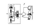
従来のシステムとは異なり、本発明の集中化スケーラブル資源システム10は、集中化資源12を複数のジョブに割り当て、各表示装置上に表示予定のマルチ画像を同時に生成するように動作できる。計算資源の割当ユニットは、例えば、CPU(中央演算処理装置)であっても良いし、視覚化資源の割当ユニットは、例えば、グラフィクス・パイプライン及びそれに関連するハードウェアまたはソフトウェアであっても良い。図2を参照すると、資源22のサブセットは、各ジョブまたは表示装置24のサブセット上に結果を表示するためのアプリケーション・ソフトウェアの実行のために割り当てられ、これにより集中化スケーラブル資源システム10は、複数のジョブを実行し、複数のアプリケーションを実行するように動作できる。資源22のサブユニットは、1つまたは複数のネットワーク化データ記憶ユニット26と、1つまたは複数の計算資源ユニット28と、1つまたは複数の視覚化資源ユニット30を有することができる。集中化されまたスケーラブルな資源アーキテクチャ及びそのシステム10は、動作中に再割当ができるようにするところの、集中化資源12と表示装置18の間で設定可能な接続性を持っている。
【0013】
図3は、本発明の教示に係るグラフィクス視覚化用のスケーラブルな集中化資源アーキテクチャ及びそのシステム10の実施形態をより詳細に示すブロック図である。集中化されたスケーラブル・アーキテクチャ及びシステム10は、スイッチ機構34に連結された複数のアプリケーション・ホストなどの計算資源14を備え、スイッチ機構34は視覚化資源16のグラフィクス・エンジン36に設定可能な接続性を与える。この図中には明確に示していないが、グラフィカル画像を生成するのに必要なデータを記憶するためのデータ記憶装置のクラスタをアプリケーション・ホスト14に連結することができる。図4を参照すると、グラフィクス・エンジン36は複数のグラフィクス・パイプライン50を有する複数のワークステーションを備え、グラフィクス・パイプライン50がアプリケーション・ホスト14からグラフィカル・データ52を受け取る。ここで、スイッチ機構34は、何れのグラフィクス・パイプラインが何れのアプリケーション・ホストからグラフィカル・データを受け取るのかを決定する。グラフィクス・パイプライン50は、例えばLANにより相互接続された主パイプラインと従パイプラインを備えて配置することができる。アプリケーションの資源の要件やジョブのサイズに応じて、ジョブについて作業しているアプリケーション・ホストの数及びグラフィクス・パイプラインの数を、アプリケーション・ホストからグラフィクス・パイプラインへの接続性を変化させることで設定することができる。スイッチ機構34は、スイッチ、ルータ、交換ネットワーク及び/または他のネットワーク装置を備えてよい。具体的には、スイッチ機構34は、その入力の何れかをその出力の何れかに連結するM×Nスイッチを備える。例えば、スイッチ機構34としては、クロスバー・スイッチ、クロス・コネクト・スイッチ、イーサネット(登録商標)・スイッチ、あるいは動作中に出力の何れかを入力に連結するように動作できる任意の装置であってよい。スイッチ入力数Mはスイッチ出力数Nと同じであってよい。フレーム・バッファ(FB)54は対応する各グラフィクス・パイプライン50に連結され、グラフィクス・パイプラインによりレンダリングされる1つまたは複数の画像フレームまたは画素データを記憶するように動作できる。フレーム・バッファ54の出力は、好ましくはDVI(ディジタル・ビデオ・インターフェース)データ56であるが、他のタイプのグラフィクス・データであってもよい。通常、DVIデータは表示画面上に表示される画素位置の座標値及びその画素のカラー値を含む。例えば、DVIデータは画素の(X,Y)座標値及びそのRGB(赤、緑、青)値を含んでよい。また、DVIデータは、画素の深度値(Z)及び画素の透明度値(α)を有してもよい。
【0014】
図3を参照すると、フレーム・バッファ54からの各出力は変換器38に連結されている。第2のスイッチ機構40が変換器38の出力に連結され、複数のIPパケットを合成装置の適切なサブセット42、IVA(インターネット視覚化アーキテクチャ)装置44、更にその先のユーザへ表示を行うための表示装置へ導く。
【0015】
図3は機能ブロック図でありまた図3中に示された複数のブロック機能を一体化してもよいことに注意すべきである。例えば、IP変換器38の機能はグラフィクス・エンジン36と一体化してもよいし、合成装置42の機能はIVA44またはスイッチ機構40と共に一体化されていてもよい。
【0016】
その動作に当たっては、アプリケーション・ホスト14は、一つまたは複数のグラフィクス・アプリケーション、もしくはグラフィクス・アプリケーションの1つまたは複数のインスタンスを実行し、1つまたは複数のグラフィカル画像をレンダリングする。グラフィカル画像は1つまたは複数の表示装置上で表示できる。スイッチ機構34は、選択されたアプリケーション・ホストの出力を、グラフィクス・エンジン36の選択されたグラフィクス・パイプラインに動作中に連結するように動作できる。したがって、複数のサーバやワークステーションやコンピュータのクラスタは、基本的には、1つまたは複数のジョブを処理する1つまたは複数のサブクラスタに構成することができる。特定のジョブを実行する一つまたは複数のアプリケーション・ホストからの出力は、画像をレンダリングするための1つまたは複数のグラフィクス・パイプラインにスイッチ機構34により結合しルーティングすることができる。IP変換器38はグラフィクス・エンジン36からの出力を受け取るものであるが、これらの変換器はDVIデータをデータパケットに変換する、つまりパケット化するように動作し、ネットワークを介した転送を容易にする。表示装置へのデータの転送に用いられるネットワークのタイプによって、変換器38は、当該ネットワークのタイプに応じたヘッダ及びプロトコル情報を挿入する。例えば、転送制御プロトコル(TCP)及びインターネット・プロトコル(IP)を転送プロトコルとして使用することができ、これにより、変換器38はグラフィクス・エンジン36内のパイプラインからの画素データをIPパケットに変換するように動作できる。第2のスイッチ機構40は、動作中に、選択された変換器の出力を選択された合成装置42の入力へ接続しルーティングするように動作できる。各合成装置42は変換器38からの1つまたは複数の画像データ・ストリームをその後に表示装置に転送される1つまたは複数の画像データ・ストリームへ変換または合成するように動作できる。この画像データは例えばデータ・パケットまたはIPパケットの形態であるため、合成装置42はヘッダ及び他の情報を取り除いた後にこのデータを処理するように動作できる。その後、IVA44は合成された画像データを圧縮し、それをパケット化し、更にそれを1つまたは複数の遠隔受信装置または表示用のクライアント装置に向けてインターネットや他の適切なネットワークなどのネットワークを介して送信する。したがって、IVAは行き先情報、プロトコル・ヘッダ及び他のデータを画像データに付加してデータ・パケットを形成するように動作できる。IVAはまた、ユーザがキーボードやマウスを用いてアプリケーション・ホスト14に入力したユーザ入力データを転送することも受け持っている。このようなユーザ入力は、アプリケーション・ホスト14及び/またはグラフィクス・エンジン36の処理を制御するのに用いることができる。このような入力を行ったユーザは、1つまたは複数の表示装置と同じ場所にいてもよいし、また表示装置から離れた所にいてもよい。
【0017】
このようにして、任意の数の計算資源ユニットが協働して動作して単一のジョブを処理することで、集中化スケーラブル資源システム10により、複数の行き先へ送られるべき複数のジョブを協働して実行できる。計算資源ユニット及び視覚化資源ユニットの割当は数多くの考慮すべき事項に基づいて決定される。図5は、本発明の実施形態に係る資源割当の決定及び実行に関する制御プロセス60を示すフローチャートである。本フローチャートの各ブロックの動作は以下の通りである。
60:資源割当て
62:ユーザがエージェントへジョブを提示する
64:エージェントが1つまたは複数のデータ記憶ロケーションを決定する
66:エージェントが計算資源要件を決定する
68:エージェントが計算資源入手可否を判定する
70:エージェントが視覚化資源要件を決定する
72:エージェントが視覚化資源入手可否を判定する
74:エージェントが資源を割り当てる
76:エージェントが通信チャネルを割り当てる
78:エージェントがジョブを開始する
80:終了
資源割当方法60はエージェント技術を用いる。、エージェントはブロック62で示されるようにユーザにより提示されたジョブを受け取るソフトウェア及び/またはハードウェアであってよい。エージェントは、ブロック64に示すように、ジョブの実行に必要なデータをどこに保存するかを決定するが、それは複数の記憶装置及び/または複数の記憶ロケーションであってよい。その後、エージェントは、ブロック66及び68に示すように、ジョブについての計算資源条件及び必要な計算資源の入手可否を決定する。グラフィカル・アプリケーションの場合、エージェントは、ブロック70及び72に示すように、視覚化資源要件及びその入手可否も決定する。そして、エージェントは、ブロック74に示すようにこれらの資源を割り当てる。割り当てられる資源量は、入手不可能な資源がある場合、提示されたジョブに要する最適な量よりも少ないことがある。次に、エージェントは、ブロック76に示すように、データ記憶装置を割り当てられた計算資源や視覚化資源へ接続するのに要する通信チャネルを決定し割り当てる。また、エージェントは、通信チャネルを決定してユーザあるは表示装置に割り当てる。エージェントは、割り当てられた適切な計算資源、視覚化資源及び合成装置を選択的に接続するように、スイッチ機構を構成する。その後、エージェントはジョブの実行を開始するか、あるいはアプリケーション・ホストにジョブの実行を開始するようにとのメッセージを送信する。プロセスはブロック80で終了する。
【0018】
集中化スケーラブル資源システム及びアーキテクチャ10は、一般的な計算アプリケーションやグラフィクス及び視覚化などの特化したアプリケーションの何れにも適用可能である。、帯域幅条件及び転送時間を低減するために実行結果だけがネットワークを介して転送されるため、資源をユーザから離れた位置に配することができる。例えば、幾つかのエンジニアリング及び設計チームがある新車を設計するために協働作業するとする。設計データ及びシュミレーション・データは中央記憶サイト側に記憶される。設計レビューの際に、複数の検討者が中央記憶サイトから遠方の多数の位置にいるとする。これらの検討者は車について幾つかの異なるシステム設計を検討するかもしれない。例えば、ある検討チームが車の外観のデザインを検討し、他の検討チームが車の外形上における風洞シミュレーションを検討し、更に他の検討チームがエンジン設計を検討するかもしれない。集中化スケーラブル資源システム10は、中央記憶サイト側で記憶された各種の設計データ・セットにアクセスし、その設計のグラフィカル画像をレンダリングし、レンダリングされたグラフィカル画像を各検討チームに送信するように動作できる。レンダリングされた画像は、各チームがレビューできるように表示される。スイッチ機構は計算資源ユニットのサブセットからの出力を、ジョブに割り当てられた視覚化資源ユニットのサブセットに接続しルーティングするように動作する。したがって、システム10は実行ジョブの要件に応じてスケーラブル、つまり規模を大きくすることも小さくすることも可能であり、また再割り当て可能である。
【0019】
以下に、本発明の実施態様の例を列挙する。
【0020】
〔実施態様1〕複数の計算資源ユニット(14)と、
複数の視覚化資源ユニット(16)と、
前記複数の視覚化資源ユニット(16)を前記複数の計算資源ユニット(14)に連結し、選択された1つまたは複数の視覚化資源ユニット(16)を、少なくとも1つのグラフィカル画像を生成するための選択された1つまたは複数の計算資源ユニット(14)に連結するように動作するスイッチ機構(34)と、
前記1つまたは複数の選択された視覚化資源ユニット(16)に連結され前記少なくとも1つのグラフィカル画像を表示するように動作する複数の表示装置(18)と
を備える集中化資源システム(10)。
【0021】
〔実施態様2〕前記複数の表示装置(18)は、ネットワーク(20)を介して前記1つまたは複数の選択された視覚化資源ユニット(16)に連結される実施態様1に記載のシステム。
【0022】
〔実施態様3〕前記複数の視覚化資源ユニット(16)は、
グラフィクス・エンジン(36)と、
前記グラフィクス・エンジン(36)に連結された複数の合成装置(42)とを備える実施態様1に記載のシステム。
【0023】
〔実施態様4〕前記複数の視覚化資源ユニット(16)は、
複数のグラフィクス・パイプライン(50)と、
複数の合成装置(42)と、
前記合成装置を前記複数のグラフィクス・パイプラインに連結する第2のスイッチ機構(40)と
を備える実施態様1に記載のシステム。
【0024】
〔実施態様5〕前記複数の視覚化資源ユニット(16)は、
複数のグラフィクス・パイプライン(50)と、
各々が対応するグラフィクス・パイプラインに連結され、グラフィクス・パイプラインからのデータをパケット化するように動作する複数の変換器(38)と、
複数の合成装置(42)と、
前記複数の合成装置を前記複数の変換器に連結する第2のスイッチ機構(40)と
を備える実施態様1記載のシステム。
【0025】
〔実施態様6〕計算資源ユニット(14)の条件を決定し、
視覚化資源ユニット(16)の条件を決定し、
前記計算資源ユニット及び視覚化資源ユニットを割り当てる
ように動作できるエージェント(62)をさらに備える実施態様1記載のシステム。
【0026】
〔実施態様7〕前記スイッチ機構(34)は、クロスバー・スイッチを備える実施態様1記載のシステム。
【0027】
〔実施態様8〕前記第2のスイッチ機構(40)は、クロスバー・スイッチを備える実施態様5記載のシステム。
【0028】
〔実施態様9〕複数の第1の計算資源ユニット(14)と、
複数の第2の計算資源ユニット(16)と、
前記複数の第2の計算資源ユニット(16)を前記複数の第1の計算資源ユニット(14)に連結し、前記複数の第1の計算資源ユニット(14)の出力を前記複数の第2の計算資源ユニット(16)の入力に選択的に連結するように動作するスイッチ機構(34)と
を備え、
前記第1及び第2の複数の計算資源ユニットは少なくとも1つの実行結果を生成するように協働して機能でき、
前記複数の第1及び第2の計算資源ユニットに連結され、前記計算資源ユニットから生成される前記実行結果を受け取るように動作できる複数の表示装置(18,24)を備える
集中化資源システム(10)。
【0029】
〔実施態様10〕前記複数の表示装置(18,24)は、ネットワーク(20)を介して前記複数の第1及び第2の計算資源ユニットに連結される実施態様9に記載のシステム。
【図面の簡単な説明】
【図1】本発明に係るスケーラブルな集中化資源アーキテクチャの実施形態を示す概略図である。
【図2】本発明に係るグラフィクスの視覚化におけるスケーラブルな集中化資源アーキテクチャ及びそのシステムの実施形態を示す概略ブロック図である。
【図3】本発明に係るグラフィクスの視覚化におけるスケーラブルな集中化資源アーキテクチャ及びそのシステムの実施形態をより詳細に示すブロック図である。
【図4】グラフィクス・エンジンの概略ブロック図である。
【図5】本発明の実施形態に係る資源割当を決定するプロセスを示すフローチャートである。
【符号の説明】
10:集中化資源システム
12:集中化資源
14:計算資源ユニット
16:視覚化資源ユニット
18:表示装置
20:ネットワーク
22:資源
24:表示装置
26:ネットワーク化データ記憶ユニット
28:計算資源ユニット
30:視覚化資源ユニット
34:スイッチ機構
36:グラフィクス・エンジン
38:変換器
40:スイッチ装置
42:合成装置
44:インターネット視覚化アーキテクチャ装置
50:グラフィクス・パイプライン
52:グラフィカル・データ
54:フレーム・バッファ
56:ディジタル・ビデオ・インターフェース・データ
62:エージェント[0001]
TECHNICAL FIELD OF THE INVENTION
The present invention relates generally to the field of computer systems, and more particularly to a centralized and scalable resource architecture and system.
[0002]
[Prior art]
In the era when mainframe and supercomputers dominate the digital world, users typically slice computational time from a fixed pool so that computers can operate in parallel for many jobs. Had been given. Users were connected to the mainframe computer using a "dumb terminal" connected to the mainframe computer and a simple command line user interface. However, computer computing environments have gradually moved to lower cost personal computers and workstations. Such an environment provides the user with more control over how the computer or workstation runs the application, and provides a better and more intuitive graphical user interface. However, particularly recently, since global connectivity has been provided by the Internet and higher bandwidths, a computer-based computing environment is referred to as a “web farm” via the Internet. Simplified, or minimal, connection to centralized data storage and computing resources provided by a system that combines multiple web (hereinafter web) servers to look like a single web server Another trend has been to move to computers and devices that have only functions. Typically, a web farm is a collection of servers, microcomputers, or mainframe computers, which now performs the web server and host functions for most web applications and web pages.
[0003]
In the computer graphics field, current computer graphical visualization systems may employ workstations or clusters of personal computers that simultaneously execute a single job of executing graphics applications and rendering images to be displayed on a display device. it can. The image is displayed as a single logical image on a single monitor screen or through a multiple monitor screen. Such a visualization system renders different parts of the display image on a display monitor screen using a plurality of graphics pipelines, speeds up processing time, and further improves the quality of the display image.
[0004]
[Means for Solving the Problems]
According to an embodiment of the present invention, a centralized resource system includes a plurality of computing resource units, a plurality of visualizing resource units, and a switching fabric for connecting the plurality of visualizing resource units to the plurality of computing resource units. ). The switch mechanism operates to couple the selected one or more visualization resource units to the selected one or more computational resource units for generating one or more graphical images. The plurality of display devices are operable to display one or more graphical images coupled to the one or more selected visualization resource units.
[0005]
According to another embodiment of the present invention, a centralized resource system includes a plurality of first computation resource units, a plurality of second computation resource units, and a plurality of second computation resource units, divided into a plurality of first computation resource units. And a switch mechanism connected to the computation resource unit. The switch mechanism operates to selectively couple the outputs of the plurality of first computational resource units to the inputs of the plurality of second computational resource units. The first and second plurality of computational resource units cooperate to generate one or more execution results. Then, a plurality of display devices are coupled to the plurality of first and second computational resource units and are operable to receive execution results from these computational resource units.
[0006]
According to yet another embodiment of the present invention, a centralized resource system comprises: a first resource means, a second resource means, and one or more outputs of the first resource means to a second resource means. A coupling means is provided for selectively coupling to one or more inputs of the means. A plurality of display means are coupled to the first and second resource means and are operable to receive and display execution results from the first and second resource means.
[0007]
Yet another embodiment of the present invention comprises a step of receiving a graphics visualization job to be performed by a plurality of computing resource units; determining a required requirement of the computing resource unit for the job; And determining the availability of the computational resource units, and allocating the computational resource units according to the determined requirements and availability of the computational resource units. The method further includes determining a plurality of destinations for receiving the results of the job, and allocating and configuring a plurality of communication channels from the assigned computational resource unit to the destinations.
[0008]
According to a further embodiment of the present invention, the graphics visualization architecture comprises a plurality of computational resource units, a plurality of graphics pipelines, and a plurality of graphics pipelines coupled to the plurality of computational resource units. 1 switch mechanism. The first switch mechanism operates to selectively couple outputs of the plurality of computational resource units to inputs of the plurality of graphics pipelines. The architecture further includes a plurality of synthesizers and a second switch mechanism for coupling the plurality of synthesizers to the plurality of graphics pipelines, wherein the second switch mechanism outputs an output of the plurality of graphics pipelines. Operate to selectively couple to the inputs of the plurality of synthesizers.
[0009]
BEST MODE FOR CARRYING OUT THE INVENTION
BRIEF DESCRIPTION OF THE DRAWINGS Embodiments of the present invention and their advantages are best understood by referring to FIGS. 1-5 of the accompanying drawings, wherein like numerals are used to indicate like corresponding parts in the various figures. Can be
[0010]
For example, current computer graphical visualization systems, such as the Hewlett-Packard Company visualization center sv6 (HPsv6), typically use a group of multiple workstations to perform visualization resource processing and produce a single image. Render a single graphical image to be displayed. HPsv6 is a U.S. patent application Ser. No. 09 / 715,335, entitled "SYSTEM AND METHOD FOR EFFICIENTLY RENDERING GRAPHICAL DATA", filed Nov. 17, 2000, filed on Nov. 17, 2000. As disclosed in the accompanying US Patent Application.
[0011]
FIG. 1 is a schematic diagram illustrating an embodiment of a system 10 formed by the scalable centralized resource architecture of the present invention. Although system 10 employs centralized resources 12, the centralized resources can comprise data storage building blocks, computing resource building blocks, and other scalable resources. For example, centralized resources 12 include personal computers, workstations, servers, and other computers 14 that can be easily added to or removed from the computing resource configuration as needed. Software such as a graphics application is executed by the computer 14 operating as a host computer. The centralized resource 12 may also be coupled to a computer 14 and include more specialized computing resources, such as graphics or visualization resources 16. The visualization resources 16 may include a graphics pipeline, a frame buffer, a compositor, and other special hardware and software resources used for graphics rendering. Such visualization resources 16 can be implemented with hardware ranging from specialized graphics cards to powerful workstations. Centralized resource 12 is coupled to a user terminal or display 18 via network 20. Network 20 may be a local area network (LAN), a wide area network (WAN), the Internet, or any other suitable network or one having connectivity. The user terminal or
[0012]
Unlike conventional systems, the centralized scalable resource system 10 of the present invention is operable to allocate centralized resources 12 to multiple jobs and simultaneously generate multiple images to be displayed on each display device. The allocation unit of computational resources may be, for example, a CPU (Central Processing Unit), or the allocation unit of visualization resources may be, for example, a graphics pipeline and hardware or software related thereto. . Referring to FIG. 2, a subset of resources 22 is allocated for execution of application software to display results on each job or subset of
[0013]
FIG. 3 is a block diagram illustrating in more detail an embodiment of a scalable centralized resource architecture for graphics visualization and system 10 according to the teachings of the present invention. The centralized scalable architecture and system 10 includes a computing resource 14, such as a plurality of application hosts, coupled to a switch mechanism 34, which has a configurable connection to a
[0014]
Referring to FIG. 3, each output from the
[0015]
It should be noted that FIG. 3 is a functional block diagram, and that a plurality of block functions shown in FIG. 3 may be integrated. For example, the function of the IP converter 38 may be integrated with the
[0016]
In operation, the application host 14 executes one or more graphics applications, or one or more instances of graphics applications, and renders one or more graphical images. The graphical image can be displayed on one or more display devices. The switch mechanism is operable to operatively couple the output of the selected application host to the selected graphics pipeline of the graphics engine. Thus, a cluster of servers, workstations, or computers can be basically configured into one or more sub-clusters that process one or more jobs. Output from one or more application hosts executing a particular job can be coupled and routed by switch mechanism 34 to one or more graphics pipelines for rendering images. The IP converters 38 receive the output from the
[0017]
In this manner, the centralized scalable resource system 10 can cooperate with a plurality of jobs to be sent to a plurality of destinations by an arbitrary number of computational resource units operating in cooperation to process a single job. Can work and run. The assignment of computational resource units and visualization resource units is determined based on a number of considerations. FIG. 5 is a flowchart illustrating a control process 60 for determining and executing resource allocation according to an embodiment of the present invention. The operation of each block in this flowchart is as follows.
60: Resource allocation
62: User presents job to agent
64: Agent determines one or more data storage locations
66: Agent determines computing resource requirements
68: Agent determines availability of computational resource
70: Agent determines visualization resource requirements
72: Agent determines availability of visualization resource
74: Agent allocates resources
76: Agent allocates communication channel
78: Agent starts job
80: End
The resource allocation method 60 uses agent technology. The agent may be software and / or hardware that receives the job submitted by the user as shown at block 62. The agent determines where to store the data needed to execute the job, as shown in
[0018]
The centralized scalable resource system and architecture 10 is applicable to both general computing applications and specialized applications such as graphics and visualization. Since only execution results are transferred over the network to reduce bandwidth requirements and transfer times, resources can be located far from the user. For example, suppose that several engineering and design teams work together to design a new car. The design data and the simulation data are stored at the central storage site. Assume that during the design review, multiple reviewers are at multiple locations remote from the central storage site. These reviewers may consider several different system designs for the car. For example, one study team might study the design of a car's exterior, another study team study a wind tunnel simulation on the car's profile, and another study team might study an engine design. The centralized scalable resource system 10 operates to access various design data sets stored at the central storage site, render a graphical image of the design, and send the rendered graphical image to each review team. it can. The rendered image is displayed for review by each team. The switch mechanism operates to connect and route output from the subset of computational resource units to the subset of visualization resource units assigned to the job. Thus, the system 10 is scalable, that is, can be made larger or smaller, and can be reassigned, depending on the requirements of the running job.
[0019]
Hereinafter, examples of embodiments of the present invention will be listed.
[0020]
[Embodiment 1] A plurality of computation resource units (14),
A plurality of visualization resource units (16);
Linking the plurality of visualization resource units (16) to the plurality of computational resource units (14) to generate at least one graphical image of the selected one or more visualization resource units (16); A switch mechanism (34) operative to couple to the selected one or more computational resource units (14);
A plurality of displays (18) coupled to the one or more selected visualization resource units (16) and operable to display the at least one graphical image;
A centralized resource system (10) comprising:
[0021]
[0022]
[Embodiment 3] The plurality of visualization resource units (16)
A graphics engine (36),
The system of claim 1, comprising a plurality of synthesizers (42) coupled to the graphics engine (36).
[0023]
[Embodiment 4] The plurality of visualization resource units (16)
A plurality of graphics pipelines (50);
A plurality of synthesizers (42);
A second switch mechanism (40) for coupling said compositing device to said plurality of graphics pipelines;
The system of embodiment 1, comprising:
[0024]
[Embodiment 5] The plurality of visualization resource units (16) include:
A plurality of graphics pipelines (50);
A plurality of converters (38) each coupled to the corresponding graphics pipeline and operable to packetize data from the graphics pipeline;
A plurality of synthesizers (42);
A second switch mechanism (40) connecting the plurality of synthesizers to the plurality of converters;
2. The system of embodiment 1, comprising:
[0025]
[Embodiment 6] The condition of the computational resource unit (14) is determined,
Determine the conditions of the visualization resource unit (16);
Assigning the computational resource unit and the visualization resource unit
The system of embodiment 1 further comprising an agent (62) operable to:
[0026]
Embodiment 7 The system of embodiment 1, wherein the switch mechanism (34) comprises a crossbar switch.
[0027]
[Eighth Embodiment] The system according to the fifth embodiment, wherein the second switch mechanism (40) includes a crossbar switch.
[0028]
[Embodiment 9] A plurality of first computation resource units (14),
A plurality of second computational resource units (16);
The plurality of second computational resource units (16) are connected to the plurality of first computational resource units (14), and an output of the plurality of first computational resource units (14) is connected to the plurality of second computational resource units (14). A switch mechanism (34) operative to selectively couple to an input of the computational resource unit (16);
With
The first and second plurality of computational resource units can cooperate to generate at least one execution result;
A plurality of display devices coupled to the plurality of first and second computational resource units and operable to receive the execution results generated from the computational resource units;
Centralized resource system (10).
[0029]
[Embodiment 10] The system according to Embodiment 9, wherein the plurality of display devices (18, 24) are connected to the plurality of first and second computation resource units via a network (20).
[Brief description of the drawings]
FIG. 1 is a schematic diagram illustrating an embodiment of a scalable centralized resource architecture according to the present invention.
FIG. 2 is a schematic block diagram illustrating an embodiment of a scalable centralized resource architecture and system for graphics visualization according to the present invention.
FIG. 3 is a block diagram illustrating in more detail an embodiment of a scalable centralized resource architecture and system for graphics visualization according to the present invention.
FIG. 4 is a schematic block diagram of a graphics engine.
FIG. 5 is a flowchart illustrating a process for determining a resource allocation according to an embodiment of the present invention.
[Explanation of symbols]
10: Centralized resource system
12: Centralized resources
14: Computational resource unit
16: Visualization resource unit
18: Display device
20: Network
22: Resources
24: Display device
26: Networked data storage unit
28: Computational resource unit
30: Visualization resource unit
34: Switch mechanism
36: Graphics Engine
38: Converter
40: Switch device
42: Synthesizer
44: Internet Visualization Architecture Device
50: Graphics Pipeline
52: Graphical data
54: Frame buffer
56: Digital video interface data
62: Agent
Claims (1)
複数の視覚化資源ユニットと、
前記複数の視覚化資源ユニットを前記複数の計算資源ユニットに連結し、選択された1つまたは複数の視覚化資源ユニットを、少なくとも1つのグラフィカル画像を生成するための選択された1つまたは複数の計算資源ユニットに連結するように動作するスイッチ機構と、
前記1つまたは複数の選択された視覚化資源ユニットに連結され前記少なくとも1つのグラフィカル画像を表示するように動作する複数の表示装置と
を備える集中化資源システム。A plurality of computational resource units;
A plurality of visualization resource units,
The plurality of visualization resource units are coupled to the plurality of computational resource units, and the selected one or more visualization resource units are connected to the selected one or more selected ones for generating at least one graphical image. A switch mechanism operative to couple to the computational resource unit;
A plurality of displays coupled to said one or more selected visualization resource units and operative to display said at least one graphical image.
Applications Claiming Priority (1)
| Application Number | Priority Date | Filing Date | Title |
|---|---|---|---|
| US10/086,060 US6909432B2 (en) | 2002-02-27 | 2002-02-27 | Centralized scalable resource architecture and system |
Publications (2)
| Publication Number | Publication Date |
|---|---|
| JP2004005449A true JP2004005449A (en) | 2004-01-08 |
| JP2004005449A5 JP2004005449A5 (en) | 2006-02-09 |
Family
ID=27753783
Family Applications (1)
| Application Number | Title | Priority Date | Filing Date |
|---|---|---|---|
| JP2003050717A Withdrawn JP2004005449A (en) | 2002-02-27 | 2003-02-27 | Centralized scalable resource architecture and its system |
Country Status (5)
| Country | Link |
|---|---|
| US (2) | US6909432B2 (en) |
| EP (2) | EP1727046A2 (en) |
| JP (1) | JP2004005449A (en) |
| CN (1) | CN1441359A (en) |
| TW (1) | TWI289763B (en) |
Cited By (6)
| Publication number | Priority date | Publication date | Assignee | Title |
|---|---|---|---|---|
| JP2007538319A (en) * | 2004-05-14 | 2007-12-27 | エヌヴィディア コーポレイション | Low power programmable processor |
| JP2014504409A (en) * | 2010-12-15 | 2014-02-20 | インターナショナル・ビジネス・マシーンズ・コーポレーション | Hardware-accelerated graphics for network-enabled applications |
| US8706930B2 (en) | 2007-10-18 | 2014-04-22 | Fujitsu Component Limited | KVM switch, method for controlling the same, switching system for multi-monitor, and switching method for multi-monitor |
| JP2015225672A (en) * | 2014-05-27 | 2015-12-14 | ディスペース デジタル シグナル プロセッシング アンド コントロール エンジニアリング ゲゼルシャフト ミット ベシュレンクテル ハフツングdspace digital signal processing and control engineering GmbH | Method and device for testing control unit |
| JP2016511853A (en) * | 2012-12-20 | 2016-04-21 | インテル・コーポレーション | Scalable computing fabric |
| US20230079054A1 (en) * | 2021-09-10 | 2023-03-16 | Exploration Robotics Technologies Inc. | System and method for autonomous inspection for asset maintenance and management |
Families Citing this family (25)
| Publication number | Priority date | Publication date | Assignee | Title |
|---|---|---|---|---|
| ES2271250T3 (en) | 2002-03-25 | 2007-04-16 | Telefonaktiebolaget Lm Ericsson (Publ) | DYNAMIC MANAGEMENT METHOD AND DEVICES FOR A SERVER APPLICATION IN A SERVER PLATFORM. |
| US7140024B2 (en) * | 2002-07-29 | 2006-11-21 | Silicon Graphics, Inc. | System and method for managing graphics applications |
| US7307961B2 (en) * | 2002-09-25 | 2007-12-11 | At&T Knowledge Ventures, L.P. | Traffic modeling for packet data communications system dimensioning |
| US8291009B2 (en) * | 2003-04-30 | 2012-10-16 | Silicon Graphics International Corp. | System, method, and computer program product for applying different transport mechanisms for user interface and image portions of a remotely rendered image |
| US8775997B2 (en) | 2003-09-15 | 2014-07-08 | Nvidia Corporation | System and method for testing and configuring semiconductor functional circuits |
| US8788996B2 (en) | 2003-09-15 | 2014-07-22 | Nvidia Corporation | System and method for configuring semiconductor functional circuits |
| US8732644B1 (en) | 2003-09-15 | 2014-05-20 | Nvidia Corporation | Micro electro mechanical switch system and method for testing and configuring semiconductor functional circuits |
| US8711161B1 (en) | 2003-12-18 | 2014-04-29 | Nvidia Corporation | Functional component compensation reconfiguration system and method |
| US20050212823A1 (en) * | 2004-03-29 | 2005-09-29 | Uthe Robert T | System, method and software for intelligent zooming in a user interface |
| US7580145B2 (en) * | 2004-07-09 | 2009-08-25 | Toshiba Corporation | Method and apparatus for effective job management |
| US20060026234A1 (en) * | 2004-07-27 | 2006-02-02 | Silicon Graphics, Inc. | System and method for networked computer graphics |
| US8723231B1 (en) | 2004-09-15 | 2014-05-13 | Nvidia Corporation | Semiconductor die micro electro-mechanical switch management system and method |
| US8711156B1 (en) | 2004-09-30 | 2014-04-29 | Nvidia Corporation | Method and system for remapping processing elements in a pipeline of a graphics processing unit |
| US20060268852A1 (en) * | 2005-05-12 | 2006-11-30 | David Rosenbluth | Lens-based apparatus and method for filtering network traffic data |
| US20060271857A1 (en) * | 2005-05-12 | 2006-11-30 | David Rosenbluth | Imaging system for network traffic data |
| US20060288296A1 (en) * | 2005-05-12 | 2006-12-21 | David Rosenbluth | Receptor array for managing network traffic data |
| US7773096B2 (en) * | 2005-12-12 | 2010-08-10 | Microsoft Corporation | Alternative graphics pipe |
| US8861591B2 (en) * | 2007-05-11 | 2014-10-14 | Advanced Micro Devices, Inc. | Software video encoder with GPU acceleration |
| US8233527B2 (en) * | 2007-05-11 | 2012-07-31 | Advanced Micro Devices, Inc. | Software video transcoder with GPU acceleration |
| US8724483B2 (en) | 2007-10-22 | 2014-05-13 | Nvidia Corporation | Loopback configuration for bi-directional interfaces |
| US20090251474A1 (en) * | 2008-04-08 | 2009-10-08 | Chou Deanna J | Virtual computing and display system and method |
| US9331869B2 (en) | 2010-03-04 | 2016-05-03 | Nvidia Corporation | Input/output request packet handling techniques by a device specific kernel mode driver |
| CN104516659A (en) * | 2013-09-27 | 2015-04-15 | 联想(北京)有限公司 | Information processing method and device |
| US11144184B2 (en) | 2014-01-23 | 2021-10-12 | Mineset, Inc. | Selection thresholds in a visualization interface |
| WO2016095187A1 (en) * | 2014-12-19 | 2016-06-23 | Intel Corporation | Apparatus and method for adding nodes to a computing cluster |
Family Cites Families (34)
| Publication number | Priority date | Publication date | Assignee | Title |
|---|---|---|---|---|
| US4845658A (en) * | 1986-12-01 | 1989-07-04 | Massachusetts Institute Of Technology | Information method and apparatus using simplex and duplex communications |
| US4965559A (en) * | 1988-05-31 | 1990-10-23 | Motorola, Inc. | Multi-channel graphics controller |
| US5321750A (en) * | 1989-02-07 | 1994-06-14 | Market Data Corporation | Restricted information distribution system apparatus and methods |
| KR100220042B1 (en) * | 1990-06-07 | 1999-09-01 | 가부시키가이샤 히타치 세이사쿠쇼 | Presentation supporting method and apparatus therefor |
| JP2770598B2 (en) * | 1990-06-13 | 1998-07-02 | 株式会社日立製作所 | Graphic display method and apparatus |
| US5241625A (en) * | 1990-11-27 | 1993-08-31 | Farallon Computing, Inc. | Screen image sharing among heterogeneous computers |
| TW198107B (en) * | 1991-02-28 | 1993-01-11 | Ibm | |
| US5446866A (en) * | 1992-01-30 | 1995-08-29 | Apple Computer, Inc. | Architecture for transferring pixel streams, without control information, in a plurality of formats utilizing addressable source and destination channels associated with the source and destination components |
| US5408606A (en) * | 1993-01-07 | 1995-04-18 | Evans & Sutherland Computer Corp. | Computer graphics system with parallel processing using a switch structure |
| JPH06301657A (en) * | 1993-02-22 | 1994-10-28 | Internatl Business Mach Corp <Ibm> | Method for parallel management |
| JP2863428B2 (en) * | 1993-05-18 | 1999-03-03 | 富士通株式会社 | Conversational graphics system |
| EP0693737A3 (en) * | 1994-07-21 | 1997-01-08 | Ibm | Method and apparatus for managing multiprocessor graphical workload distribution |
| US6972786B1 (en) * | 1994-12-30 | 2005-12-06 | Collaboration Properties, Inc. | Multimedia services using central office |
| US5752246A (en) * | 1995-06-07 | 1998-05-12 | International Business Machines Corporation | Service agent for fulfilling requests of a web browser |
| US5794016A (en) * | 1995-12-11 | 1998-08-11 | Dynamic Pictures, Inc. | Parallel-processor graphics architecture |
| KR100269106B1 (en) * | 1996-03-21 | 2000-11-01 | 윤종용 | Multiprocessor graphics system |
| US5940086A (en) * | 1997-01-10 | 1999-08-17 | Hewlett Packard Company | System and method for dynamically allocating data among geometry accelerators in a computer graphics system |
| JPH10304180A (en) * | 1997-04-25 | 1998-11-13 | Fuji Xerox Co Ltd | Drawing processor and drawing processing method |
| US5996013A (en) * | 1997-04-30 | 1999-11-30 | International Business Machines Corporation | Method and apparatus for resource allocation with guarantees |
| JP3474078B2 (en) * | 1997-05-02 | 2003-12-08 | 富士ゼロックス株式会社 | Drawing processing device |
| US5968120A (en) * | 1997-05-02 | 1999-10-19 | Olivr Corporation Ltd. | Method and system for providing on-line interactivity over a server-client network |
| US6002409A (en) * | 1997-10-29 | 1999-12-14 | Cirrus Logic, Inc. | Arbitration for shared graphics processing resources |
| US6104392A (en) * | 1997-11-13 | 2000-08-15 | The Santa Cruz Operation, Inc. | Method of displaying an application on a variety of client devices in a client/server network |
| US6611241B1 (en) * | 1997-12-02 | 2003-08-26 | Sarnoff Corporation | Modular display system |
| US6085216A (en) * | 1997-12-31 | 2000-07-04 | Xerox Corporation | Method and system for efficiently allocating resources for solving computationally hard problems |
| US6269275B1 (en) * | 1998-03-31 | 2001-07-31 | Michael G. Slade | Method and system for customizing and distributing presentations for user sites |
| US6249294B1 (en) * | 1998-07-20 | 2001-06-19 | Hewlett-Packard Company | 3D graphics in a single logical sreen display using multiple computer systems |
| US6292200B1 (en) * | 1998-10-23 | 2001-09-18 | Silicon Graphics, Inc. | Apparatus and method for utilizing multiple rendering pipes for a single 3-D display |
| US7158094B2 (en) * | 1998-10-30 | 2007-01-02 | Ati International Srl | Method and apparatus for supporting multiple displays |
| US6570579B1 (en) * | 1998-11-09 | 2003-05-27 | Broadcom Corporation | Graphics display system |
| US6973653B1 (en) * | 1999-10-21 | 2005-12-06 | Sony Corporation | Method for utilizing resource characterizations to optimize performance in an electronic device |
| JP2003515265A (en) * | 1999-10-21 | 2003-04-22 | ソニー エレクトロニクス インク | Method for quantifying available system resources in electronic devices |
| KR20020007036A (en) * | 2000-07-14 | 2002-01-26 | 김선민 | A computer with several image producing means |
| US6819327B2 (en) * | 2001-05-18 | 2004-11-16 | Sun Microsystems, Inc. | Signature analysis registers for testing a computer graphics system |
-
2002
- 2002-02-27 US US10/086,060 patent/US6909432B2/en not_active Expired - Lifetime
- 2002-11-21 TW TW091133968A patent/TWI289763B/en not_active IP Right Cessation
-
2003
- 2003-02-13 EP EP06076742A patent/EP1727046A2/en not_active Withdrawn
- 2003-02-13 EP EP03250894A patent/EP1343085A3/en not_active Withdrawn
- 2003-02-27 CN CN03106632A patent/CN1441359A/en active Pending
- 2003-02-27 JP JP2003050717A patent/JP2004005449A/en not_active Withdrawn
-
2005
- 2005-04-15 US US11/108,080 patent/US20050174353A1/en not_active Abandoned
Cited By (10)
| Publication number | Priority date | Publication date | Assignee | Title |
|---|---|---|---|---|
| JP2007538319A (en) * | 2004-05-14 | 2007-12-27 | エヌヴィディア コーポレイション | Low power programmable processor |
| JP4914829B2 (en) * | 2004-05-14 | 2012-04-11 | エヌヴィディア コーポレイション | Low power programmable processor |
| US8706930B2 (en) | 2007-10-18 | 2014-04-22 | Fujitsu Component Limited | KVM switch, method for controlling the same, switching system for multi-monitor, and switching method for multi-monitor |
| JP2014504409A (en) * | 2010-12-15 | 2014-02-20 | インターナショナル・ビジネス・マシーンズ・コーポレーション | Hardware-accelerated graphics for network-enabled applications |
| JP2016511853A (en) * | 2012-12-20 | 2016-04-21 | インテル・コーポレーション | Scalable computing fabric |
| JP2017194974A (en) * | 2012-12-20 | 2017-10-26 | インテル・コーポレーション | Scalable compute fabric |
| JP2015225672A (en) * | 2014-05-27 | 2015-12-14 | ディスペース デジタル シグナル プロセッシング アンド コントロール エンジニアリング ゲゼルシャフト ミット ベシュレンクテル ハフツングdspace digital signal processing and control engineering GmbH | Method and device for testing control unit |
| JP2020102225A (en) * | 2014-05-27 | 2020-07-02 | ディスペース デジタル シグナル プロセッシング アンド コントロール エンジニアリング ゲゼルシャフト ミット ベシュレンクテル ハフツングdspace digital signal processing and control engineering GmbH | Method and device for testing control unit |
| JP6995393B2 (en) | 2014-05-27 | 2022-01-14 | ディスペース ゲー・エム・ベー・ハー | Methods and equipment for testing control units |
| US20230079054A1 (en) * | 2021-09-10 | 2023-03-16 | Exploration Robotics Technologies Inc. | System and method for autonomous inspection for asset maintenance and management |
Also Published As
| Publication number | Publication date |
|---|---|
| TW200303475A (en) | 2003-09-01 |
| TWI289763B (en) | 2007-11-11 |
| CN1441359A (en) | 2003-09-10 |
| US20030160795A1 (en) | 2003-08-28 |
| US20050174353A1 (en) | 2005-08-11 |
| EP1343085A2 (en) | 2003-09-10 |
| US6909432B2 (en) | 2005-06-21 |
| EP1727046A2 (en) | 2006-11-29 |
| EP1343085A3 (en) | 2006-07-05 |
Similar Documents
| Publication | Publication Date | Title |
|---|---|---|
| JP2004005449A (en) | Centralized scalable resource architecture and its system | |
| US7812843B2 (en) | Distributed resource architecture and system | |
| US10043482B2 (en) | Client-server visualization system with hybrid data processing | |
| CN108388460B (en) | Remote real-time rendering platform construction method based on graphic cluster | |
| US7808499B2 (en) | PC-based computing system employing parallelized graphics processing units (GPUS) interfaced with the central processing unit (CPU) using a PC bus and a hardware graphics hub having a router | |
| JP4434973B2 (en) | Video display device, video composition distribution device, program, system and method | |
| JP2008538620A (en) | Graphics processing and display system using multiple graphics cores on a monolithic silicon chip | |
| WO2015118875A1 (en) | Optimal arrangement method for virtual network function, network control device, network management device, and network system | |
| CN116319303A (en) | Network card virtualization method based on DPU cross-card link aggregation | |
| US11561840B2 (en) | Efficient inter-chip interconnect topology for distributed parallel deep learning | |
| Date et al. | SDN-accelerated hpc infrastructure for scientific research | |
| Date et al. | An empirical study of sdn-accelerated hpc infrastructure for scientific research | |
| Hansen et al. | Impact of gigabit network research on scientific visualization | |
| Maassen et al. | Assessing the impact of future reconfigurable optical networks on application performance | |
| Guimarães et al. | Frame lock synchronization for multiprojection immersive environments based on pc graphics clusters | |
| Mohamed et al. | Configurable communication middleware for clusters with multiple interconnections | |
| Brown et al. | OpenGL Vizserver 3.1–Application transparent remote interactive visualization and collaboration | |
| CN114168524A (en) | Line cache unit, acceleration unit, system on chip and line cache configuration method | |
| CN102542524A (en) | Cluster workstation and method for realizing same | |
| JP2005275933A (en) | Three-dimensional graphics creating system, method and program |
Legal Events
| Date | Code | Title | Description |
|---|---|---|---|
| RD02 | Notification of acceptance of power of attorney |
Free format text: JAPANESE INTERMEDIATE CODE: A7422 Effective date: 20051024 |
|
| RD04 | Notification of resignation of power of attorney |
Free format text: JAPANESE INTERMEDIATE CODE: A7424 Effective date: 20051026 |
|
| A521 | Written amendment |
Free format text: JAPANESE INTERMEDIATE CODE: A523 Effective date: 20051117 |
|
| A621 | Written request for application examination |
Free format text: JAPANESE INTERMEDIATE CODE: A621 Effective date: 20051117 |
|
| A521 | Written amendment |
Free format text: JAPANESE INTERMEDIATE CODE: A523 Effective date: 20051129 |
|
| A521 | Written amendment |
Free format text: JAPANESE INTERMEDIATE CODE: A523 Effective date: 20051129 |
|
| A761 | Written withdrawal of application |
Free format text: JAPANESE INTERMEDIATE CODE: A761 Effective date: 20080402 |