【0001】
【発明の属する技術分野】
本発明は、試料中の分析対象物の定性または定量分析を行う特異結合分析方法に関する。
【0002】
【従来の技術】
近年、家庭内および地域医療の充実や、緊急性の高い臨床検査等の増加に伴い、臨床検査の専門家でなくとも、迅速、簡便かつ正確に計測が実施できる特異結合分析方法の開発がとみに望まれるようになってきた。
特異結合分析方法としては、抗原抗体反応を応用したイムノアッセイ、受容体を用いたレセプターアッセイ、相補的核酸配列のハイブリダイゼーションを用いた核酸プローブアッセイなど多くの方法が知られている、これらの特異結合分析方法は、その特異性の高さから、臨床検査をはじめとする広い分野で繁用されている。
【0003】
さらに具体的には、イムノアッセイの1種であるクロマトグラフ分析法が挙げられる。このクロマトグラフ分析法においては、例えば、特異結合物質が不溶化された多孔性担体または微粒子充填型単体からなるマトリクスに液状試料を接触させ、液状試料がマトリクスに沿って毛細管現象による浸透力によって流出することを利用し、試料中の分析対象物の存否を分析する(日本国特許第2504923号および特許第2667793号各明細書、ならびに特公平7−78503号、特開平10−73592号および特開平8−240591号各公報)。
【0004】
具体的には、裸眼または光学的方法などにより任意に検知できる標識材によって標識された特異結合物質と分析対象物とを特異結合反応させる。そして、分析対象物と特異結合反応した特異結合物質をマトリクス上に固定化された結合材に結合させ、マトリクス上に固定された標識量に応じて、最終的に試料中の分析対象物の存否を分析するのである。
このクロマトグラフ分析法は、マトリクスにおける担体の表面積が大きいため、多量の特異結合物質を不溶化することができ、特異結合反応を引き起こしうる反応分子間の衝突頻度が液相中における反応の場合に比して大きいため、計測感度および計測時間の面から有利である。
【0005】
上記の従来のクロマトグラフ分析法では、マトリクスとして、毛細管現象により液体試料を展開輸送可能な吸水性材料を用いることが必要である。この吸水性材料としては、例えばガラス繊維ろ紙、セルロース膜、ニトロセルロース膜、ナイロン膜などが挙げられる。これらは、多孔性で1〜50μm程度の孔径を有する孔を持つものが用いられる。
特に、ニトロセルロースは、あらかじめ増感しなくても多量の抗体のような蛋白質と結合する能力を有するため優れている。さらに、種々の孔径を有するニトロセルロースを入手することができるため、これを用いれば試料の流速を選択することも可能である。
【0006】
【発明が解決しようとする課題】
しかしながら、上記のようなマトリクス材料は繊維状材料からなるが、孔径および表面の親水性を再現性良く制御して生産することが難しい。この孔径の平均値および分布状況、ならびに繊維状表面の親水性は、試料の展開輸送速度、すなわち流速に大きく影響する。特異結合反応が発生している時間はこの流速に大きく依存するため、計測値も流速変化により変動する。すなわち、計測値が、マトリクス材料の特性に非常に敏感に反応するため、計測精度はマトリクス材料の製造精度に依存する。
そして、このマトリクス材料の製造精度を、定量計測の充分な精度を確保するまで向上させることは難しい。したがって、マトリクス材料の選別工程が必要になり、コストがかかるという問題があった。また、孔径の範囲やその製造精度に制限があるため、試料流速の選択幅も限られている。
【0007】
また、上記に対応して、広い範囲において流速を容易に制御することができ、流速の製造再現性が高い特異結合分析方法およびこれに用いる特異結合分析デバイスが、特願2001−322447号明細書に記載されている。しかし、特願2001−322447号明細書に開示されている内容では、第2の特異結合物質と結合しなかった成分が検出部に残留することがあり、この残留成分には、標識材が含まれていることがある。したがって、検出部におけるこの残留標識材が、検出信号に重畳されることがあった。すなわち、残留標識材に起因して、検出信号のバックグラウンドが上昇し、この結果、計測のS/Nが低下することがあった。
【0008】
そこで、本発明は、流速の制御範囲が広くかつ流速の製造再現性が高く、さらに、検出信号のバックグラウンドの上昇を回避できる特異結合分析方法、およびこれに用いる特異結合分析デバイスを提供することを目的とする。本発明により、試料流速の選択幅を拡大することができ、また製造レベルにおいても流速を高精度に再現できる。さらに、本発明によれば、検出信号のバックグラウンドの上昇を回避できるため、高精度な特異結合分析デバイスを低コストで実現することができる。
【0009】
【課題を解決するための手段】
上記問題を解決するために、本発明は、分析対象物を含んだ液状の試料を点着する試料点着部と、前記試料点着部と連結された毛細管現象を呈する空間形成部と、前記空間形成部内において特異結合反応に由来して得られた信号を検出し得る検出部とを具備し、前記点着された前記試料が、毛細管現象により前記空間形成部内の前記検出部に移動して特異結合反応が発生し、当該特異結合反応に由来した信号を検出することで前記分析対象物を定性または定量する特異結合分析デバイスを用い、前記検出部よりも前記試料の移動方向における下流側において、前記空間形成部で呈する毛細管現象による液体輸送力を大きくすることを特徴とする特異結合分析方法を提供する。
【0010】
前記特異結合分析方法においては、前記試料が前記検出部を通過する速度を制御することにより、前記特異結合反応が発生している時間を制御するのが好ましい。
また、前記空間形成部の外部雰囲気に通じる部分の断面積および距離を制御することにより、前記試料が前記検出部を通過する速度を制御し、前記特異結合反応が発生している時間を制御するのが好ましい。
また、前記空間形成部の外部雰囲気に通じる部分に第1の通気性部材を配置することにより、前記試料が前記検出部を通過する速度を制御し、前記特異結合反応が発生している時間を制御するのが好ましい。
なお、「空間形成部の外部雰囲気に通じる部分」とは、空間形成部において、試料点着部以外の部分であって、かつ試料が毛細管現象で輸送されるときに押し出される空気が通過できるような位置に相当する部分をいう。
【0011】
また、毛細管現象により発現する吸水特性を有する第2の通気性部材を、前記検出部よりも前記試料の移動方向の下流側に配置することにより、毛細管現象による液体輸送力を大きくするのが好ましい。
さらに、前記特異結合分析方法は、前記分析対象物と特異的に結合しかつ検出可能な標識材により標識された第1の特異結合物質と、前記分析対象物を結合させる工程A、前記分析対象物と特異的に結合しかつ前記検出部に実質的に固定化された第2の特異結合物質と、前記分析対象物を結合させる工程B、前記検出部で発生し前記標識材に由来して得られた信号の強度を計測する工程C、および前記工程Cにおいて計測された信号の強度に基づいて、前記試料中の分析対象物を定性または定量する工程Dを有するのが好ましい。
【0012】
また、前記試料点着部に所定容量の前記試料を点着した後、前記工程Bにおいて前記第2の特異結合物質と結合しなかった成分を、毛細管現象によって前記空間形成部内の前記検出部よりも前記試料の移動方向における下流側に移動させるのが好ましい。
また、前記工程Cにおいて、前記第1の特異結合物質と前記第2の特異結合物質とを前記分析対象物を介して結合させるのが好ましい。
【0013】
前記第1の特異結合物質を、前記試料点着部と前記検出部との間における前記空間形成部の前記試料との接触面上に保持し、前記試料が点着され湿潤状態になることによって、前記第1の特異結合物質を前記接触面で可動化させて前記検出部へ移動させるのが好ましい。
前記信号は呈色、蛍光または発光であるのが好ましく、前記第1の特異結合物質および第2の特異結合物質の少なくとも一方が抗体であるのが好ましい。また、前記標識材が金属ゾル、染料ゾル、蛍光物質を含んだ粒子または着色ラテックス粒子であるのが好ましい。
【0014】
さらに、本発明は、分析対象物を含んだ液状の試料を点着する試料点着部と、前記試料点着部と連結された毛細管現象を呈する空間形成部と、前記空間形成部内において特異結合反応に由来して得られた信号を検出し得る検出部とを具備し、前記点着された前記試料が、毛細管現象により前記空間形成部内の前記検出部に移動して特異結合反応が発生し、当該特異結合反応に由来した信号を検出することで前記分析対象物を定性または定量する特異結合分析デバイスであって、さらに前記空間形成部で呈する毛細管現象による液体輸送力を、前記検出部よりも前記試料の移動方向における下流側において大きくする手段を具備することを特徴とする特異結合分析デバイスに関する。
【0015】
前記特異結合分析デバイスは、前記空間形成部の外部雰囲気に通じる部分に配置された第1の通気性部材を具備するのが好ましい。
また、前記手段は、毛細管現象により発現する吸水特性を有し、かつ前記検出部よりも前記試料の移動方向の下流側において配置された第2の通気性部材であるのが好ましい。
【0016】
また、前記特異結合分析デバイスにおいては、前記第1の特異結合物質を、前記試料点着部と前記検出部との間における前記空間形成部の前記試料との接触面上に保持し、前記試料が点着され湿潤状態になることによって、前記第1の特異結合物質を前記接触面で可動化させて前記検出部へ移動させることが有効である。
【0017】
また、前記空間形成部が二枚の平板と前記平板の間隔を規定するスペーサとで構成され、前記検出部が前記平板上に設けられ、前記特異結合反応に由来した信号を前記平板を介して検出することが有効である。
【0018】
【発明の実施の形態】
本発明は、分析対象物を含んだ液状の試料を点着する試料点着部と、前記試料点着部と連結された毛細管現象を呈する空間形成部と、前記空間形成部内において特異結合反応に由来して得られた信号を検出し得る検出部とを具備し、前記点着された前記試料が、毛細管現象により前記空間形成部内の前記検出部に移動して特異結合反応が発生し、当該特異結合反応に由来した信号を検出することで前記分析対象物を定性または定量する特異結合分析デバイスを用い、
前記検出部よりも前記試料の移動方向における下流側において、前記空間形成部で呈する毛細管現象による液体輸送力を大きくすることを特徴とする特異結合分析方法に関する。
【0019】
ここで、液体輸送力とは、毛細管現象により液体を輸送する能力を意味する。液体輸送力が大きいということは、空間形成部の液体と接触する面の親水性が高くかつ液体の保持量が大きいということである。したがって、前記検出部よりも前記試料の移動方向における下流側において、前記空間形成部で呈する毛細管現象による液体輸送力を大きくすると、前記検出部に液体が到達すると、全液体が下流側に輸送される。ただし、点着された前記試料の量が、下流側液体の保持量以下であることが必要である。
【0020】
さらに、本発明は、かかる特異結合分析方法に用いる特異結合分析デバイスにも関する。この特異結合分析デバイスは、分析対象物を含んだ液状の試料を点着する試料点着部と、前記試料点着部と連結された毛細管現象を呈する空間形成部と、前記空間形成部内において特異結合反応に由来して得られた信号を検出し得る検出部とを具備し、前記点着された前記試料が、毛細管現象により前記空間形成部内の前記検出部に移動して特異結合反応が発生し、当該特異結合反応に由来した信号を検出することで前記分析対象物を定性または定量する特異結合分析デバイスであって、さらに前記空間形成部で呈する毛細管現象による液体輸送力を、前記検出部よりも前記試料の移動方向における下流側において大きくする手段を具備することを特徴とする。
【0021】
以下、本発明の実施の形態について、図面を参照しながら詳細に説明する。
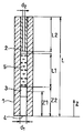
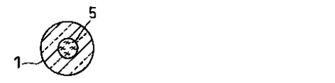
図1は、本発明の一実施の形態に係る特異結合分析デバイスの構成を示す概略断面図である。また、図2は、図1に示すZ方向から見た前記特異結合分析デバイスの概略図である。
このデバイスは、例えば内径(d1)が5mm、長さ(L)が30mmの空間形成部を構成するガラス製の第1の毛細管1、および内径(d2)が0.5mm、長さ(L2)が3mm、外径が約5mmの通気抵抗制御手段としての役割を果たすガラス製の第2の毛細管2で構成されている。
【0022】
図1に示すように、第2の毛細管2は第1の毛細管1の管内に挿入されている。ここで、第2の毛細管2の外側面と第1の毛細管1の内側面は密着しており、実質的に空気はこの間を透過できない。第2の毛細管2と第1の毛細管1とは、例えば接着剤で密着して接合されている。
第1の毛細管1の内部には検出部3が設けられており、この検出部3は、結合材として第2の特異結合物質が第1の毛細管1の内壁に固定化されて形成されている。また、この検出部3は、第1の毛細管1の開口部4(第2の毛細管2が挿入されていない側)からの距離(Z1)約2mmの部分に位置しており、Z方向における検出部3の長さは約1mmである。なお、Z1は、開口部4の端部から検出部3の中心までの距離を示している。
【0023】
また、第1の毛細管1の内部には、ガラス繊維濾紙GA200(東洋株式会社製)を直径5mm、長さ(L2)20mmの寸法に加工して得た通気性部材である吸水性部材5が挿入されている。吸水性部材5の一端は、第1の毛細管1内の開口部4より距離(Z2)約3mmの部分に位置しており、検出部3に接している。本実施の形態においては、開口部4が試料点着部としての役割を果たす。
【0024】
図1に示す特異結合分析デバイスを、開口部4を下に向け、かつ前記デバイスの長さ方向が水平方向に対して実質的に垂直になるように配置し、開口部4を試料の表面に接触させる。そうすると、試料の液面が毛細管現象によりZ方向へ移動する。すなわち、試料の液面が上昇する。このとき、試料の表面張力の鉛直方向成分と、上昇した試料の柱に働く重力とが釣り合うまで、試料の液面が移動(上昇)する。
【0025】
図1に示す特異結合分析デバイスから第2の毛細管2および吸水性部材5を取り除き、通常の大気圧および室温の雰囲気で、試料として尿などの水溶液を用いた場合、試料の液面の移動(上昇)距離Zは約6mmであった。このとき、液面は約2〜3秒間で6mm移動して静止した。
しかし、図1に示すデバイスから吸水性部材5のみを除き、通常の大気圧および室温の雰囲気で、試料として尿などの水溶液を用いた場合、移動(上昇)距離Zは約6mmであった。このとき、液面は、約30秒間で6mm移動して静止した。これは、以下の理由からである。
【0026】
毛細管現象により試料が上に移動するのに伴って、空気は試料に押されるため空気も移動する。ここで、第1の毛細管1の開口部4の反対側が完全に封止されていれば、空気が圧縮されるため圧力が上昇する。そして、この圧縮された空気の圧力と大気圧との差、すなわち上昇した圧力分がさらに重力に加わるため、試料は6mmも上昇せずに静止する。ところが、第1の毛細管1の開口部4の反対側が完全には封止されていなければ、試料の移動により圧縮された空気は徐々に抜けるため、最終的には大気圧と平衡状態になり、試料は6mm上昇して静止する。
【0027】
ただし、静止するまでの時間は、第1の毛細管1の開口部4の反対側が完全に開放されている場合(第2の毛細管2が無い状態)に比べると増加する。換言すると、試料の移動速度は低下する。この移動速度の低下度合いは、第1の毛細管1の開口部4の反対側の通気抵抗に依存する。この通気抵抗は第2の毛細管2の有無で変化するため、移動速度も第2の毛細管2の有無で変化する。具体的には、第2の毛細管2が無い場合は、ある場合に比べると通気抵抗が低下し、移動速度が増加する。
【0028】
これらのことから、第1の毛細管1の開口部4の反対側の通気抵抗を制御することで、試料の移動速度を制御できることがわかる。ここで、第2の毛細管2の内径(d2)が小さいほど、換言すると内部空間(空間形成部)の断面積が小さいほど通気抵抗が大きくなり、第2の毛細管2の長さが長いほど通気抵抗が大きくなる。例えば、第2の毛細管2の内径(d2)が1.0mm、長さ(L)が3mmの場合は、7〜10秒間で6mm上昇して静止した。また、第2の毛細管2の内径(d2)が0.5mm、長さ(L)が2mmの場合は、20〜25秒間で6mm上昇して静止した。
【0029】
上述した移動速度は、吸水性部材5が無い場合の移動速度である。吸水性部材5を挿入すると当然通気抵抗が大きくなるため、第2の毛細管2の有無、第2の毛細管2の内径および長さが上記と同一条件であっても、移動速度は上記よりも小さくなる。ただし、図1に示すような配置を採用した場合は、吸水性部材5の一端が、第1の毛細管1内の開口部4より距離(Z2)約3mmの部分に位置しているため、試料の液面は、6mm上昇する前に、吸水性部材5の一端に到達する。そして、試料は吸水性部材5に吸収される。
【0030】
つぎに、試料点着部に点着される試料の容量について述べる。試料の容量が、液面が6mm上昇するのに必要な容量以上である場合は、液面が吸水性部材5の一端に到達するので、これに吸収される。ここで、検出部3上にある第2の特異結合物質に結合しなかった成分すべてを吸水性部材5に吸収させ、検出部3に残留させないようにする必要がある。したがって、試料点着部に点着される試料の容量は、吸水性部材5に吸水され得る試料の最大容量以下である必要がある。
【0031】
具体的には、上記構造の吸水性部材5が吸水し得る試料の最大容量は約0.2ml以上であった。また、試料の液面を6mm上昇させるのに必要な前記試料の容量は約0.12mlであった。したがって、試料の容量が0.12〜0.2mlの範囲であれば、検出部3上にある第2の特異結合物質に結合しなかった試料中の成分すべてを、吸水性部材5に吸収させて、検出部3に残留させないことができた。一般的に述べると、毛細管現象により移動する試料の液面が到達しうる位置に吸水性部材5の一端(下端)を配置し、同時に点着する試料の容量が、吸水性部材5の下端に到達し得る容量以上で、かつ吸水性部材5が吸水し得る最大容量以下であてばよい。
【0032】
以上のように、第1の毛細管1の開口部4の反対側の通気抵抗を制御することで、試料が検出部3を通過する速度を制御し、特異結合反応が発生している時間を制御することができる。したがって、特異結合反応の反応を反映する信号強度も制御することができ、分析における感度や濃度範囲を自由に設定することができる。さらに、第1の毛細管1内で呈する毛細管現象による液体輸送力を、検出部よりも試料の移動方向における下流側で、吸水性部材5の存在により大きくすることができる。そのため、第2の特異結合物質と結合しなかった成分が検出部に残留することがなく、検出信号のバックグラウンドが上昇することを回避することができ、信号のS/Nの低下を防止することができる。なお、上記した数値は、開口部4を下に向け、かつ前記デバイスの長さ方向が水平方向に対して実質的に垂直になるように配置した場合に得られる。これ以外の配置の場合は、上記の数値は異なるが、当業者であれば実験的に適宜選択し得る。
【0033】
また、開口部4の反対側の通気抵抗を、吸水性部材5自身の通気抵抗によって制御することで、移動速度を制御することもできる。ここでは、必要な吸水能力を確保した上で、ガラス繊維濾紙GA200の密度および長さなどを制御することで、通気抵抗を制御することができる。すなわち、吸水性部材5に吸水効果と通気抵抗制御効果を発揮させることで、実現することができる。
以下に、実施例を用いて本発明をより具体的に説明するが、本発明はこれらのみに限定されるものではない。
【0034】
【実施例】
《実施例1および比較例1》
本実施例では、上述した図1に示す本発明に係る特異結合分析デバイスを用い、分析対象物として尿中のヒト絨毛性性線刺激ホルモン(hCG)を分析した。第1の特異結合物質および第2の特異結合物質としては、hCGとのサンドイッチ反応に参加し得る抗hCGモノクローナル抗体を用い、標識材としては金コロイドを用いた。ここで、金コロイドのような着色粒子を用いる場合、着色粒子が微細なため、標識を小さな区域または容積の中に集中させることが可能であり、検出部3において第1の特異結合物質の標識材である金コロイドが寄与する反応に由来する信号を用いてhCGの定性または定量を正確に行うことができた。また、第1の毛細管1にスキムミルクの分散水溶液を通すことによってその内壁をブロッキングした。
【0035】
まず、尿と金コロイドで標識された抗hCGモノクローナル抗体との混合溶液を調製し、この混合溶液を試料とした。この状態の試料中では、分析対象物であるhCGとが金コロイドで標識された抗hCGモノクローナル抗体と結合していた。この試料を試料点着部である開口部4に約0.15ml点着したところ、試料は毛細管現象により上昇し検出部3を通過した。そして、約1分経過後には、見かけ上、液体成分すべて吸水性部材5に吸収され検出部3上には液体成分は残留しなかった。
【0036】
このとき、点着された試料中の分析対象物は、第2の特異結合物質と特異結合した。これにより、分析対象物は、第2の特異結合物質を介して検出部3に固定された。すなわち、金コロイドで標識された第1の特異結合物質である抗hCGモノクローナル抗体は、分析対象物hCGを介して検出部3に固定化された第2の特異結合物質である抗hCGモノクローナル抗体と結合した。これにより検出部3において、分析対象物hCGの濃度に応じて発色した。ここで、検出部3上には、第2の特異結合物質と特異結合しなかった金コロイド成分が残留しなかったため、吸水性部材5が存在しない場合に比べて、コントラストは遥かに大きかった。
【0037】
hCG濃度が実質的にゼロである精度管理用のコントロール尿に、hCGを添加して種々の濃度の試料を調製した。これらの各試料を用い、上述のような原理に基づいて検出部3における金コロイドによる発色度合いを確認した。各試料のhCG濃度は、それぞれ0(IU/L)、3(IU/L)、10(IU/L)、30(IU/L)、100(IU/L)、300(IU/L)、1000(IU/L)、3000(IU/L)および10000(IU/L)であった。その結果、10(IU/L)以上のhCG濃度を有する試料を用いると発色を確認することができた。
【0038】
つぎに、吸水性部材5を省略した場合についても、同様に実験を行った。この場合は、試料が毛細管現象によって上昇し、試料の上面が約30〜35秒間で約5mm移動して静止した。そして、300(IU/L)以上のhCG濃度を有する試料を用いると発色を確認することができた。
さらに、吸水性部材5および第2の毛細管2を省略した場合についても、同様に実験を行った。この場合は、試料が毛細管現象によって上昇し、試料の上面が約2〜3秒間で約5mm移動して静止した。そして、10000(IU/L)のhCGの濃度を有する試料を用いた場合のみ発色を確認できた。
【0039】
以上、説明したように、本発明に係る特異結合分析デバイスによると、第1の毛細管1の開口部4の反対側の通気抵抗を制御することで、試料が検出部3を通過する速度を制御することがでた。さらに、第1の毛細管1内で呈する毛細管現象による液体輸送力を、検出部よりも試料の移動方向における下流側で、吸水性部材5の存在により大きくすることができた。そのため、第2の特異結合物質と結合しなかった成分が検出部に残留せず、検出信号のバックグラウンドが上昇することを回避でき、信号のS/Nの低下を防止することができた。これらにより信号強度の制御と、信号のS/Nの向上による最小検出濃度を向上させることができた。
【0040】
なお、本実施例では、点着前に金コロイドで標識された第1の特異結合物質と尿とを混合したが、当該第1の特異結合物質を、試料点着部である開口部4と検出部3との間に乾燥状態で保持させてもよい。これにより、尿をそのまま開口部4に点着して分析することができる。この場合、液体試料である尿により、乾燥状態で保持された第1の特異結合物質が湿潤状態になって自由に移動することができ、分析対象物と第1の特異結合物質とが結合した状態で、検出部3に移動し、同様に濃度に応じた発色をさせることができる。
【0041】
《実施例2》
つぎに、図3に示す本発明に係る特異結合分析デバイスを用い、分析対象物として尿中のヒト絨毛性性線刺激ホルモン(hCG)を分析した。図3に、本発明の別の実施の形態に係る特異結合分析デバイスの構成を示す概略断面図を示した。また、図4に、図3に示すZ方向から見た前記特異結合分析デバイスの概略図を示した。
図3において、第1の毛細管1、検出部3および試料点着部である開口部4は、図1のものと同じとした。ただし、第2の毛細管2は存在せず、吸水性部材5の長さL1を変化させ、通気抵抗を制御した。言い換えると、吸水性部材に通気性部材としての機能も発揮させた。
【0042】
本実施例においては、実施例1と同様にガラス繊維濾紙GA200(東洋株式会社製)を直径5mm、長さ(L2)20mmの寸法に加工して得た吸水性部材5と、直径5mm、長さ25mmの寸法に加工し得た吸水性部材5’を用いた。これ以外は実施例1で用いた特異結合分析デバイスと同じ構成を採用した。吸水性部材5’は吸水性部材5よりも体積が大きいため、その吸水能力および通気抵抗も吸水性部材5よりも大きかった。
【0043】
まず、吸水性部材5を用いた図3および4に示すデバイスで、本実施例においても、実施例1と同様に尿と金コロイドで標識された抗hCGモノクローナル抗体との混合溶液を調製し、この混合溶液を試料として開口部4に点着した。この試料を試料点着部である開口部4に約0.15ml点着したところ、試料は毛細管現象により上昇し検出部3を通過した。そして、約30〜40秒経過後には、見かけ上、液体成分すべて吸水性部材5に吸収され検出部3上には液体成分は残留しなかった。
【0044】
また、実施例1と同様にして、hCG濃度が実質的にゼロである精度管理用のコントロール尿にhCGを添加して種々の濃度の試料を調製し、検出部3における金コロイドによる発色度合いを確認した。各試料のhCG濃度は、それぞれ0(IU/L)、3(IU/L)、10(IU/L)、30(IU/L)、100(IU/L)、300(IU/L)、1000(IU/L)、3000(IU/L)および10000(IU/L)とした。その結果、30(IU/L)以上のhCG濃度を有する試料を用いた場合は発色を確認することができた。
【0045】
つぎに、長さを変化させた吸水性部材5’を用いた図3および4に示すデバイスで、上記と同様に試料を試料点着部である開口部4に約0.15ml点着した。試料は毛細管現象により上昇し検出部3を通過した。そして、約50〜60秒経過後には、見かけ上、液体成分すべて吸水性部材5に吸収され検出部3上には液体成分は残留しなかった。さらに、上記と同様にして、hCG濃度が実質的にゼロである精度管理用のコントロール尿にhCGを添加して種々の濃度の試料を調製し、検出部3における金コロイドによる発色度合いを確認した。
【0046】
各試料のhCG濃度は、それぞれ0(IU/L)、3(IU/L)、10(IU/L)、30(IU/L)、100(IU/L)、300(IU/L)、1000(IU/L)、3000(IU/L)および10000(IU/L)とした。その結果、10(IU/L)以上のhCG濃度を有する試料を用いた場合は発色を確認することができた。
以上のように、吸水性部材5の長さを変化させることにより、通気抵抗を変化させ、移動速度を制御することができ、各濃度に対する発色度合いを調整することができた。
【0047】
以上、説明したように、本実施例に係る特異結合分析デバイスによれば、ガラス製の第1の毛細管1の開口部4の反対側の通気抵抗を吸水性部材で制御することで、信号強度も制御することができた。ここでは、必要な吸水能力を確保した上で、ガラス繊維濾紙GA200の密度、長さ等を制御することで、通気抵抗を制御することができる。即ち、吸水性部材5に吸水効果と通気抵抗制御効果を発揮させることで、実現することができた。
【0048】
《実施例3》
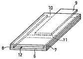
本実施例においては、図5および6に示す特異結合分析デバイスを用いた。図5に、本発明に係る別の特異結合分析デバイスの分解斜視図を示した。図5に示すように、本特異結合分析デバイスは、ガラスまたは樹脂で構成された基板6、ガラスまたは樹脂または金属などで構成されたスペーサー7および8(x方向の厚みは50μm程度)、ガラス繊維濾紙GA200(東洋株式会社製)で構成された吸水性部材9(x方向の厚みは50μm程度)、ならびにガラスまたは樹脂からなる透明基板10を用いて作製した。また、基板6上には、第2の特異結合物質であるhCGとのサンドイッチ反応に参加し得る抗hCGモノクローナル抗体を固定化して検出部11を形成した。
【0049】
図6に、図5に示す特異結合分析デバイスの合体斜視図を示した。図6に示すように、透明基板10を、スペーサー7および8を介して基板6と重ねた。これによって、基板6、スペーサー7および8ならびに透明基板10で、内部に空間形成部を構成した。そして、同時にこの空間形成部へ試料を導入することができる試料点着部12を構成できた。なお、本デバイスでは、通気抵抗は、スペーサー7および8の厚さ(x方向)、吸水性部材9を構成するガラス繊維濾紙の密度、吸水性部材9とスペーサー7および8との隙間(y方向)、または前記隙間の長さ(z方向)を調整することによって制御することができた。
【0050】
本実施例では、図5および6に示す本発明に係る特異結合分析デバイスを用い、分析対象物として尿中のヒト絨毛性性線刺激ホルモン(hCG)を分析した。第1の特異結合物質および第2の特異結合物質としては、hCGとのサンドイッチ反応に参加し得る抗hCGモノクローナル抗体を用い、標識材としては蛍光ラッテクス用いた。本実施例では、反射吸光分光計を用い、検出部の第2の特異結合物質と特異結合した蛍光ラテックスによる蛍光強度を計測し、hCGの定量を正確に行うことができた。具体的には、検出部11に、本蛍光ラテックスの励起波長に相当する光を照射し、検出部11で発生した蛍光波長に相当する光のみを分光して計測した。
また、検出部11を作成した後、基板6および透明基板10で構成された空間形成部の内壁にスキムミルクの分散水溶液を塗布し、乾燥することによって前記内壁をブロッキングした。
【0051】
まず、尿と金コロイドで標識された抗hCGモノクローナル抗体との混合溶液を調製し、この混合溶液を試料とした。この状態の試料中では、分析対象物であるhCGとが金コロイドで標識された抗hCGモノクローナル抗体と結合していた。この試料を試料点着部である開口部4に所定容量点着した。この所定容量とは、毛細管現象で吸水性部材9の一端に到達し得る容量以上の容量であり、吸水性部材9が吸水し得る最大容量以下とした。ただし、定量性を確保するためには、毎回同一容量を点着する必要があった。点着後、試料は毛細管現象により上昇し検出部11を通過した。そして、約5分経過後には、見かけ上、液体成分すべて吸水性部材9に吸収され検出部11上には液体成分は残留しなかった。
【0052】
このとき、点着された試料中の分析対象物は、第2の特異結合物質と特異結合した。これにより、分析対象物は、第2の特異結合物質を介して検出部3に固定された。すなわち、蛍光ラッテクスで標識された第1の特異結合物質である抗hCGモノクローナル抗体は、分析対象物hCGを介して検出部3に固定化された第2の特異結合物質である抗hCGモノクローナル抗体と結合した。これにより検出部3において、分析対象物hCGの濃度に応じた蛍光を発した。ここで、検出部11上には、第2の特異結合物質と特異結合しなかった蛍光ラッテクスが残留しなかったため、吸水性部材9が存在しない場合に比べて、バックグラウンドは、大幅に低下した。
【0053】
hCG濃度が実質的にゼロである精度管理用のコントロール尿に、hCGを添加して種々の濃度の試料を調製し、上述のような原理に基づいて検出部11における蛍光ラッテクスによる蛍光強度を計測した。各試料のhCG濃度は、それぞれ0(IU/L)、3(IU/L)、10(IU/L)、30(IU/L)、100(IU/L)、300(IU/L)、1000(IU/L)、3000(IU/L)および10000(IU/L)であった。その結果、10(IU/L)以上のhCG濃度を有する試料で蛍光を確認でき、かつこの蛍光強度の直線性は1000(IU/L)まで確認できた。すなわち、10(IU/L)から1000(IU/L)までの定量性を確認できた。
この定量特性は、通気抵抗を調整することで、制御することができた。すなわち、最低検出濃度や、直線性を示す最高濃度を制御することができた。
【0054】
以上、説明したように、本実施の形態による特異結合分析デバイスによると、試料点着部12の反対側の通気抵抗を制御することで、試料が検出部11を通過する速度を制御することができた。さらに、空間形成部内で呈する毛細管現象による液体輸送力を、検出部11よりも試料の移動方向側で、吸水性部材9の存在により大きくする吸水性部材9の効果で、第2の特異結合物質と結合しなかった成分が検出部に残留することがないため、検出信号のバックグラウンド低減でき、信号のS/Nが向上した。これらにより定量性の制御と、信号のS/Nの向上による最小検出濃度を向上させることができた。
【0055】
なお、本実施例では、点着前に標識された第1の特異結合物質と尿とを混合していたが、当該第1の特異結合物質を、試料点着部12と検出部11との間に乾燥状態で保持させてもよい。これにより、尿をそのまま試料点着部12に点着して分析することができる。この場合、液体試料である尿により、乾燥状態で保持された第1の特異結合物質が湿潤状態になって自由に移動することができ、分析対象物と第1の特異結合物質とが結合した状態で、検出部11に移動し、同様に濃度に応じた蛍光を発生させることができる。
以上、説明したように、本実施例に係る特異結合分析デバイスによると、分析における感度や濃度範囲を自由に設定することができた。
【0056】
【発明の効果】
以上のように、本発明の特異結合分析方法およびこれに用いるデバイスによれば、試料が検出部を通過する速度を制御することができ、さらに、検出部に第2の特異結合物質により固定化されなかった成分が残留しにくいため感度や濃度範囲を自由に設定することができ、感度も向上した。これらにより、本発明は実用上極めて有効である。
【図面の簡単な説明】
【図1】本発明の一実施の形態に係る特異結合分析デバイスの構成を示す概略断面図である。
【図2】図1に示すZ方向から見た前記特異結合分析デバイスの概略図である。
【図3】本発明の別の実施の形態に係る特異結合分析デバイスの構成を示す概略断面図である。
【図4】図3に示すZ方向から見た前記特異結合分析デバイスの概略図である。
【図5】本発明のさらに別の実施の形態に係る特異結合分析デバイスの分解斜視図である。
【図6】図5に示す特異結合分析デバイスの合体斜視図である。
【符号の説明】
1 第1の毛細管
2 第2の毛細管
3 検出部
4 開口部
5 吸水性部材[0001]
TECHNICAL FIELD OF THE INVENTION
The present invention relates to a specific binding analysis method for performing qualitative or quantitative analysis of an analyte in a sample.
[0002]
[Prior art]
In recent years, with the enhancement of home and regional medical care and the increase of urgent clinical tests, the development of specific binding analysis methods that can perform measurement quickly, easily, and accurately, even without a specialist in clinical tests, is undeniable. It has come to be desired.
Many specific binding analysis methods are known, such as an immunoassay utilizing an antigen-antibody reaction, a receptor assay using a receptor, and a nucleic acid probe assay using hybridization of a complementary nucleic acid sequence. Analysis methods are widely used in a wide range of fields including clinical tests due to their high specificity.
[0003]
More specifically, a chromatographic analysis method, which is a type of immunoassay, can be mentioned. In this chromatographic analysis method, for example, a liquid sample is brought into contact with a matrix consisting of a porous carrier or a fine particle-filled simple substance in which a specific binding substance is insolubilized, and the liquid sample flows out along the matrix by osmotic force due to capillary action. This is utilized to analyze the presence or absence of an analyte in a sample (Japanese Patent Nos. 2,504,923 and 2,667,793, and Japanese Patent Publication Nos. 7-78503, 10-73592, and 8). -240591 publications).
[0004]
Specifically, a specific binding reaction is caused between a specific binding substance labeled with a labeling material that can be optionally detected by the naked eye or an optical method and an analyte. Then, the specific binding substance that has undergone a specific binding reaction with the analyte is bound to the binding material immobilized on the matrix, and finally, depending on the amount of label immobilized on the matrix, the presence or absence of the analyte in the sample is determined. Is analyzed.
In this chromatographic analysis method, since the surface area of the carrier in the matrix is large, a large amount of the specific binding substance can be insolubilized, and the collision frequency between the reaction molecules that can cause the specific binding reaction is lower than that in the reaction in the liquid phase. This is advantageous in terms of measurement sensitivity and measurement time.
[0005]
In the above-mentioned conventional chromatographic analysis method, it is necessary to use, as a matrix, a water-absorbing material capable of developing and transporting a liquid sample by capillary action. Examples of the water absorbing material include glass fiber filter paper, cellulose membrane, nitrocellulose membrane, nylon membrane and the like. These are porous and have pores having a pore diameter of about 1 to 50 μm.
In particular, nitrocellulose is excellent because it has the ability to bind to a large amount of proteins such as antibodies without prior sensitization. Furthermore, since nitrocellulose having various pore sizes can be obtained, it is possible to select the flow rate of the sample by using this.
[0006]
[Problems to be solved by the invention]
However, although the matrix material as described above is made of a fibrous material, it is difficult to control the pore size and the hydrophilicity of the surface with good reproducibility for production. The average value and distribution state of the pore diameter and the hydrophilicity of the fibrous surface greatly affect the developing and transporting speed of the sample, that is, the flow speed. Since the time during which the specific binding reaction occurs is greatly dependent on the flow rate, the measured value also varies with the change in the flow rate. That is, the measured values are very sensitive to the properties of the matrix material, so that the measurement accuracy depends on the manufacturing accuracy of the matrix material.
It is difficult to improve the manufacturing accuracy of this matrix material until sufficient accuracy of quantitative measurement is secured. Therefore, there is a problem that a step of selecting a matrix material is required, and the cost is increased. Further, the range of the hole diameter and the manufacturing accuracy are limited, so that the selection range of the sample flow rate is also limited.
[0007]
Further, in response to the above, a specific binding analysis method and a specific binding analysis device which can easily control the flow rate in a wide range and have high production reproducibility of the flow rate are disclosed in Japanese Patent Application No. 2001-322447. It is described in. However, in the contents disclosed in Japanese Patent Application No. 2001-322447, a component that did not bind to the second specific binding substance may remain in the detection unit, and the residual component contains a labeling material. May have been. Therefore, the residual marker in the detection unit may be superimposed on the detection signal. That is, the background of the detection signal increases due to the residual marker, and as a result, the S / N of the measurement may decrease.
[0008]
Therefore, the present invention provides a specific binding analysis method which has a wide flow rate control range and high flow rate production reproducibility, and can avoid an increase in the background of a detection signal, and a specific binding analysis device used for the method. With the goal. According to the present invention, the selection range of the sample flow rate can be expanded, and the flow rate can be reproduced with high accuracy even at the production level. Furthermore, according to the present invention, an increase in the background of the detection signal can be avoided, so that a highly accurate specific binding analysis device can be realized at low cost.
[0009]
[Means for Solving the Problems]
In order to solve the above problems, the present invention provides a sample spotting section for spotting a liquid sample containing an analyte, a space forming section exhibiting a capillary phenomenon connected to the sample spotting section, Comprising a detection unit capable of detecting a signal derived from a specific binding reaction in the space forming unit, wherein the spotted sample moves to the detecting unit in the space forming unit by capillary action. A specific binding reaction occurs, using a specific binding analysis device for qualitatively or quantitatively determining the analyte by detecting a signal derived from the specific binding reaction, on the downstream side in the moving direction of the sample from the detection unit. The present invention also provides a specific binding analysis method characterized by increasing a liquid transporting force due to a capillary phenomenon exhibited in the space forming part.
[0010]
In the specific binding analysis method, it is preferable that the time during which the specific binding reaction occurs is controlled by controlling the speed at which the sample passes through the detection unit.
Further, by controlling a cross-sectional area and a distance of a portion of the space forming portion that communicates with the external atmosphere, a speed at which the sample passes through the detecting portion is controlled, and a time during which the specific binding reaction occurs is controlled. Is preferred.
Further, by arranging the first air-permeable member in a portion of the space forming portion that communicates with the external atmosphere, the speed at which the sample passes through the detection portion is controlled, and the time during which the specific binding reaction occurs is reduced. It is preferable to control.
The “portion of the space forming portion that communicates with the external atmosphere” means a portion other than the sample spotting portion in the space forming portion, and allows the air pushed out when the sample is transported by capillary action to pass through. Refers to the part corresponding to the position.
[0011]
In addition, it is preferable that the second gas-permeable member having a water absorbing property expressed by a capillary phenomenon is disposed downstream of the detection unit in the moving direction of the sample, so that the liquid transport force by the capillary phenomenon is increased. .
Further, in the specific binding analysis method, a step A of binding the analyte with a first specific binding substance specifically bound to the analyte and labeled with a detectable labeling material, Step B, in which the second specific binding substance specifically bound to the substance and substantially immobilized on the detection section, and the analyte, are bound, and are generated in the detection section and derived from the labeling material. The method preferably includes a step C of measuring the intensity of the obtained signal, and a step D of qualitatively or quantitatively determining an analyte in the sample based on the intensity of the signal measured in the step C.
[0012]
In addition, after spotting the predetermined volume of the sample on the sample spotting part, the component that did not bind to the second specific binding substance in the step B is converted from the detection part in the space forming part by a capillary phenomenon. It is also preferable to move the sample to the downstream side in the moving direction of the sample.
Further, in the step C, it is preferable that the first specific binding substance and the second specific binding substance are bound via the analyte.
[0013]
By holding the first specific binding substance on the contact surface of the space forming portion between the sample spotting portion and the detection portion with the sample, the sample is spotted and becomes wet. Preferably, the first specific binding substance is mobilized on the contact surface and moved to the detection unit.
The signal is preferably coloration, fluorescence or luminescence, and at least one of the first specific binding substance and the second specific binding substance is preferably an antibody. Preferably, the labeling material is a metal sol, a dye sol, particles containing a fluorescent substance, or colored latex particles.
[0014]
Furthermore, the present invention provides a sample spotting portion for spotting a liquid sample containing an analyte, a space forming portion exhibiting a capillary phenomenon connected to the sample spotting portion, and a specific bond in the space forming portion. A detection unit capable of detecting a signal obtained from the reaction, wherein the spotted sample moves to the detection unit in the space forming unit by capillary action, and a specific binding reaction occurs. A specific binding analysis device for qualitatively or quantifying the analyte by detecting a signal derived from the specific binding reaction, further comprising a liquid transport force due to a capillary phenomenon exhibited by the space forming portion, And a means for increasing the size of the sample on the downstream side in the moving direction of the sample.
[0015]
It is preferable that the specific binding analysis device includes a first gas-permeable member disposed at a portion of the space forming portion that communicates with an external atmosphere.
Further, it is preferable that the means is a second gas-permeable member having a water-absorbing property expressed by a capillary phenomenon, and disposed on the downstream side of the detection unit in the moving direction of the sample.
[0016]
Further, in the specific binding analysis device, the first specific binding substance is held on a contact surface of the space forming portion between the sample spotting portion and the detection portion with the sample, and the sample is It is effective to mobilize the first specific binding substance on the contact surface and move the first specific binding substance to the detection section by being spotted and brought into a wet state.
[0017]
Further, the space forming portion is constituted by two flat plates and a spacer that defines an interval between the flat plates, and the detecting portion is provided on the flat plate, and a signal derived from the specific binding reaction is passed through the flat plate. It is effective to detect.
[0018]
BEST MODE FOR CARRYING OUT THE INVENTION
The present invention provides a sample spotting section for spotting a liquid sample containing an analyte, a space forming section exhibiting a capillary phenomenon connected to the sample spotting section, and a specific binding reaction in the space forming section. A detection unit capable of detecting a signal obtained from the sample, wherein the spotted sample moves to the detection unit in the space forming unit due to a capillary phenomenon, and a specific binding reaction occurs. Using a specific binding analysis device to qualitatively or quantitatively the analyte by detecting a signal derived from the specific binding reaction,
The present invention relates to a specific binding analysis method, characterized in that a liquid transport force due to a capillary phenomenon exhibited by the space forming section is increased downstream of the detection section in the moving direction of the sample.
[0019]
Here, the liquid transporting power means the ability to transport liquid by capillary action. A large liquid transport force means that the surface of the space forming portion that comes into contact with the liquid has high hydrophilicity and a large liquid holding amount. Therefore, when the liquid transporting force due to the capillary action exhibited by the space forming section is increased on the downstream side in the moving direction of the sample from the detecting section, when the liquid reaches the detecting section, all the liquid is transported to the downstream side. You. However, it is necessary that the amount of the spotted sample is equal to or less than the holding amount of the downstream liquid.
[0020]
Further, the present invention also relates to a specific binding analysis device used for such a specific binding analysis method. The specific binding analysis device includes a sample spotting section for spotting a liquid sample containing an analyte, a space forming section exhibiting a capillary phenomenon connected to the sample spotting section, and a specific spot in the space forming section. A detection unit capable of detecting a signal derived from the binding reaction, wherein the spotted sample moves to the detection unit in the space forming unit by capillary action, and a specific binding reaction occurs. A specific binding analysis device for qualitatively or quantitatively determining the analyte by detecting a signal derived from the specific binding reaction, further comprising a liquid transport force due to a capillary phenomenon exhibited by the space forming portion, Means for increasing the size of the sample on the downstream side in the moving direction of the sample.
[0021]
Hereinafter, embodiments of the present invention will be described in detail with reference to the drawings.
FIG. 1 is a schematic sectional view showing the configuration of the specific binding analysis device according to one embodiment of the present invention. FIG. 2 is a schematic diagram of the specific binding analysis device viewed from the Z direction shown in FIG.
This device has, for example, a first capillary tube 1 made of glass constituting a space forming part having an inner diameter (d1) of 5 mm and a length (L) of 30 mm, and an inner diameter (d2) of 0.5 mm and a length (L2). Is 3 mm and the outer diameter is about 5 mm. The second capillary 2 is made of glass and serves as a ventilation resistance control means.
[0022]
As shown in FIG. 1, the second capillary 2 is inserted into the first capillary 1. Here, the outer side surface of the second capillary tube 2 and the inner side surface of the first capillary tube 1 are in close contact with each other, and substantially no air can pass therethrough. The second capillary tube 2 and the first capillary tube 1 are tightly joined with, for example, an adhesive.
A detection unit 3 is provided inside the first capillary 1, and the detection unit 3 is formed by fixing a second specific binding substance as a binding material to the inner wall of the first capillary 1. . The detection unit 3 is located at a distance (Z1) of about 2 mm from the opening 4 (the side where the second capillary 2 is not inserted) of the first capillary 1 and detects in the Z direction. The length of the part 3 is about 1 mm. Note that Z1 indicates the distance from the end of the opening 4 to the center of the detection unit 3.
[0023]
Further, inside the first capillary tube 1, a water-absorbing member 5, which is a gas-permeable member obtained by processing glass fiber filter paper GA200 (manufactured by Toyo Corporation) to dimensions of 5 mm in diameter and 20 mm in length (L2), is provided. Has been inserted. One end of the water absorbing member 5 is located at a distance (Z2) of about 3 mm from the opening 4 in the first capillary tube 1 and is in contact with the detection unit 3. In the present embodiment, the opening 4 serves as a sample spotting portion.
[0024]
The specific binding analysis device shown in FIG. 1 is arranged so that the opening 4 faces downward and the length direction of the device is substantially perpendicular to the horizontal direction, and the opening 4 is placed on the surface of the sample. Make contact. Then, the liquid surface of the sample moves in the Z direction due to capillary action. That is, the liquid level of the sample rises. At this time, the liquid level of the sample moves (rises) until the vertical component of the surface tension of the sample and the gravity acting on the raised column of the sample are balanced.
[0025]
When the second capillary tube 2 and the water absorbing member 5 are removed from the specific binding analysis device shown in FIG. 1 and an aqueous solution such as urine is used as a sample in a normal atmosphere and at room temperature, the liquid level of the sample moves ( Ascent) The distance Z was about 6 mm. At this time, the liquid surface moved 6 mm in about 2 to 3 seconds and stopped.
However, when only the water absorbing member 5 was removed from the device shown in FIG. 1 and an aqueous solution such as urine was used as a sample in a normal atmospheric pressure and room temperature atmosphere, the moving (elevating) distance Z was about 6 mm. At this time, the liquid surface moved 6 mm in about 30 seconds and stopped. This is for the following reason.
[0026]
As the sample moves upward due to the capillary action, the air is pushed by the sample, so the air moves. Here, if the side opposite to the opening 4 of the first capillary tube 1 is completely sealed, the pressure is increased because the air is compressed. Then, the difference between the pressure of the compressed air and the atmospheric pressure, that is, the increased pressure is further applied to gravity, so that the sample does not rise by 6 mm and stops. However, if the opposite side of the opening 4 of the first capillary 1 is not completely sealed, the air compressed by the movement of the sample gradually escapes, and eventually becomes in equilibrium with the atmospheric pressure, The sample rises by 6 mm and stands still.
[0027]
However, the time until the stationary state is increased as compared with the case where the opposite side of the opening 4 of the first capillary 1 is completely opened (the state without the second capillary 2). In other words, the moving speed of the sample decreases. The degree of the decrease in the moving speed depends on the airflow resistance on the opposite side of the opening 4 of the first capillary tube 1. Since the ventilation resistance changes depending on the presence or absence of the second capillary tube 2, the moving speed also changes depending on the presence or absence of the second capillary tube 2. Specifically, when the second capillary 2 is not provided, the airflow resistance is reduced and the moving speed is increased as compared with the case where the second capillary 2 is provided.
[0028]
From these facts, it can be understood that the moving speed of the sample can be controlled by controlling the airflow resistance on the opposite side of the opening 4 of the first capillary tube 1. Here, the smaller the inner diameter (d2) of the second capillary 2, in other words, the smaller the cross-sectional area of the internal space (space forming portion), the greater the ventilation resistance, and the longer the length of the second capillary 2, the greater the ventilation. Resistance increases. For example, when the inner diameter (d2) of the second capillary 2 was 1.0 mm and the length (L) was 3 mm, the second capillary 2 rose 6 mm in 7 to 10 seconds and stopped. When the inner diameter (d2) of the second capillary 2 was 0.5 mm and the length (L) was 2 mm, the second capillary 2 rose 6 mm in 20 to 25 seconds and stopped.
[0029]
The above-described moving speed is a moving speed when the water absorbing member 5 is not provided. When the water-absorbing member 5 is inserted, the ventilation resistance naturally increases, so that the moving speed is lower than the above even if the presence or absence of the second capillary tube 2 and the inner diameter and length of the second capillary tube 2 are the same as above. Become. However, when the arrangement as shown in FIG. 1 is employed, one end of the water-absorbing member 5 is located at a distance (Z2) of about 3 mm from the opening 4 in the first capillary tube 1, so that the sample Reaches one end of the water absorbing member 5 before rising by 6 mm. Then, the sample is absorbed by the water absorbing member 5.
[0030]
Next, the capacity of the sample spotted on the sample spotting part will be described. If the volume of the sample is equal to or larger than the volume required for the liquid level to rise by 6 mm, the liquid level reaches one end of the water absorbing member 5 and is absorbed thereby. Here, it is necessary that the water-absorbing member 5 absorbs all components that did not bind to the second specific binding substance on the detection unit 3 so that the components do not remain in the detection unit 3. Therefore, the volume of the sample spotted on the sample spotting portion needs to be equal to or less than the maximum capacity of the sample that can be absorbed by the water absorbing member 5.
[0031]
Specifically, the maximum capacity of the sample that the water absorbing member 5 having the above structure can absorb water was about 0.2 ml or more. The volume of the sample required to raise the liquid level of the sample by 6 mm was about 0.12 ml. Therefore, if the volume of the sample is in the range of 0.12 to 0.2 ml, the water-absorbing member 5 absorbs all components in the sample that have not been bound to the second specific binding substance on the detection unit 3. As a result, it could not be left in the detection unit 3. Generally speaking, one end (lower end) of the water absorbing member 5 is arranged at a position where the liquid level of the sample moving due to the capillary phenomenon can reach, and the volume of the sample to be spotted at the same time is lower than the lower end of the water absorbing member 5. What is necessary is that the capacity is not less than the capacity that can be reached and not more than the maximum capacity that the water absorbing member 5 can absorb water.
[0032]
As described above, by controlling the airflow resistance on the opposite side of the opening 4 of the first capillary 1, the speed at which the sample passes through the detection unit 3 is controlled, and the time during which the specific binding reaction occurs is controlled. can do. Therefore, the signal intensity reflecting the reaction of the specific binding reaction can be controlled, and the sensitivity and the concentration range in the analysis can be freely set. Further, the liquid transporting force due to the capillary phenomenon exhibited in the first capillary tube 1 can be increased by the presence of the water absorbing member 5 on the downstream side of the detection unit in the moving direction of the sample. Therefore, components that have not bound to the second specific binding substance do not remain in the detection unit, and it is possible to avoid an increase in the background of the detection signal, thereby preventing a decrease in the S / N of the signal. be able to. The above numerical values are obtained when the device is arranged so that the opening 4 is directed downward and the longitudinal direction of the device is substantially perpendicular to the horizontal direction. In the case of other arrangements, the above numerical values are different, but those skilled in the art can appropriately select them experimentally.
[0033]
In addition, by controlling the ventilation resistance on the opposite side of the opening 4 by the ventilation resistance of the water-absorbing member 5 itself, the moving speed can be controlled. Here, the ventilation resistance can be controlled by controlling the density and length of the glass fiber filter paper GA200 after securing the necessary water absorption capacity. That is, it can be realized by causing the water absorbing member 5 to exhibit a water absorbing effect and a ventilation resistance controlling effect.
Hereinafter, the present invention will be described more specifically with reference to Examples, but the present invention is not limited thereto.
[0034]
【Example】
<< Example 1 and Comparative Example 1 >>
In this example, human chorionic gonadotropin (hCG) in urine was analyzed as an analyte using the specific binding analysis device according to the present invention shown in FIG. 1 described above. An anti-hCG monoclonal antibody capable of participating in a sandwich reaction with hCG was used as the first specific binding substance and the second specific binding substance, and gold colloid was used as the labeling material. Here, in the case of using colored particles such as gold colloid, since the colored particles are fine, it is possible to concentrate the label in a small area or volume, and the detection unit 3 labels the first specific binding substance. The qualitative or quantitative determination of hCG could be accurately performed using the signal derived from the reaction contributed by the gold colloid as the material. Further, the inner wall of the first capillary 1 was blocked by passing an aqueous dispersion of skim milk.
[0035]
First, a mixed solution of urine and an anti-hCG monoclonal antibody labeled with colloidal gold was prepared, and this mixed solution was used as a sample. In the sample in this state, the analyte hCG was bound to the anti-hCG monoclonal antibody labeled with colloidal gold. When about 0.15 ml of this sample was spotted on the opening 4 as a sample spot, the sample rose by capillary action and passed through the detecting section 3. After a lapse of about one minute, apparently, all the liquid components were absorbed by the water absorbing member 5 and no liquid components remained on the detection unit 3.
[0036]
At this time, the analyte in the spotted sample specifically bound to the second specific binding substance. Thereby, the analyte was fixed to the detection unit 3 via the second specific binding substance. That is, the anti-hCG monoclonal antibody which is the first specific binding substance labeled with colloidal gold is different from the anti-hCG monoclonal antibody which is the second specific binding substance immobilized on the detection unit 3 via the analyte hCG. Joined. As a result, the detection section 3 developed a color in accordance with the concentration of the analyte hCG. Here, since the gold colloid component that did not specifically bind to the second specific binding substance did not remain on the detection unit 3, the contrast was much higher than when the water absorbing member 5 was not present.
[0037]
Samples of various concentrations were prepared by adding hCG to control urine for quality control in which the hCG concentration was substantially zero. Using these samples, the degree of color development by the gold colloid in the detection unit 3 was confirmed based on the above-described principle. The hCG concentration of each sample was 0 (IU / L), 3 (IU / L), 10 (IU / L), 30 (IU / L), 100 (IU / L), 300 (IU / L), respectively. 1000 (IU / L), 3000 (IU / L) and 10,000 (IU / L). As a result, when a sample having an hCG concentration of 10 (IU / L) or more was used, color development could be confirmed.
[0038]
Next, the same experiment was performed when the water absorbing member 5 was omitted. In this case, the sample rose by capillary action, and the upper surface of the sample moved about 5 mm in about 30 to 35 seconds and stopped. When a sample having an hCG concentration of 300 (IU / L) or more was used, color development could be confirmed.
Further, the same experiment was performed when the water absorbing member 5 and the second capillary tube 2 were omitted. In this case, the sample rose by capillary action, and the upper surface of the sample moved about 5 mm in about 2 to 3 seconds and stopped. Color development was confirmed only when a sample having a hCG concentration of 10,000 (IU / L) was used.
[0039]
As described above, according to the specific binding analysis device of the present invention, the speed at which the sample passes through the detection unit 3 is controlled by controlling the airflow resistance on the opposite side of the opening 4 of the first capillary tube 1. Could do it. Further, the liquid transporting force due to the capillary action exhibited in the first capillary tube 1 could be increased by the presence of the water absorbing member 5 on the downstream side of the detection unit in the moving direction of the sample. For this reason, components that did not bind to the second specific binding substance did not remain in the detection unit, and it was possible to avoid an increase in the background of the detection signal, thereby preventing a reduction in the S / N of the signal. Thus, it was possible to control the signal intensity and improve the minimum detection density by improving the S / N of the signal.
[0040]
In the present embodiment, the urine was mixed with the first specific binding substance labeled with colloidal gold before the spotting, but the first specific binding substance was mixed with the opening 4 as the sample spotting part. You may make it hold | maintain in the dry state between the detection parts 3. Thus, the urine can be spotted on the opening 4 and analyzed. In this case, the urine, which is a liquid sample, allows the first specific binding substance held in a dry state to move freely in a wet state, and the analyte and the first specific binding substance are bound. In this state, the detection unit 3 moves to the detection unit 3 and can similarly generate a color corresponding to the density.
[0041]
<< Example 2 >>
Next, human chorionic gonadotrophin (hCG) in urine was analyzed as an analyte using the specific binding analysis device according to the present invention shown in FIG. FIG. 3 is a schematic cross-sectional view illustrating a configuration of a specific binding analysis device according to another embodiment of the present invention. FIG. 4 shows a schematic diagram of the specific binding analysis device viewed from the Z direction shown in FIG.
In FIG. 3, the first capillary 1, the detection unit 3, and the opening 4 as the sample spotting unit are the same as those in FIG. However, the second capillary 2 was not present, and the length L1 of the water absorbing member 5 was changed to control the airflow resistance. In other words, the water-absorbing member also exhibited a function as a breathable member.
[0042]
In this embodiment, a water-absorbing member 5 obtained by processing a glass fiber filter paper GA200 (manufactured by Toyo Corporation) into a size of 5 mm in diameter and 20 mm in length (L2) in the same manner as in Example 1; The water-absorbing member 5 'processed to a size of 25 mm was used. Except for this, the same configuration as the specific binding analysis device used in Example 1 was adopted. Since the water absorbing member 5 ′ has a larger volume than the water absorbing member 5, the water absorbing ability and the ventilation resistance are larger than the water absorbing member 5.
[0043]
First, a mixed solution of urine and an anti-hCG monoclonal antibody labeled with colloidal gold was prepared in the same manner as in Example 1 using the device shown in FIGS. 3 and 4 using the water-absorbing member 5, This mixed solution was spotted on the opening 4 as a sample. When about 0.15 ml of this sample was spotted on the opening 4 as a sample spot, the sample rose by capillary action and passed through the detecting section 3. Then, after a lapse of about 30 to 40 seconds, apparently, all of the liquid components were absorbed by the water absorbing member 5 and no liquid components remained on the detection unit 3.
[0044]
Further, in the same manner as in Example 1, hCG was added to control urine for quality control in which the hCG concentration was substantially zero, and samples of various concentrations were prepared. confirmed. The hCG concentration of each sample was 0 (IU / L), 3 (IU / L), 10 (IU / L), 30 (IU / L), 100 (IU / L), 300 (IU / L), respectively. 1000 (IU / L), 3000 (IU / L) and 10,000 (IU / L). As a result, when a sample having an hCG concentration of 30 (IU / L) or more was used, color development could be confirmed.
[0045]
Next, with the device shown in FIGS. 3 and 4 using the water-absorbing member 5 'having a changed length, about 0.15 ml of the sample was spotted on the opening 4 as the sample spotting part in the same manner as described above. The sample rose by the capillary action and passed through the detection unit 3. After a lapse of about 50 to 60 seconds, apparently, all of the liquid components were absorbed by the water absorbing member 5 and no liquid components remained on the detection unit 3. Further, in the same manner as described above, hCG was added to control urine for precision control in which the hCG concentration was substantially zero, and samples of various concentrations were prepared, and the degree of coloring by the gold colloid in the detection unit 3 was confirmed. .
[0046]
The hCG concentration of each sample was 0 (IU / L), 3 (IU / L), 10 (IU / L), 30 (IU / L), 100 (IU / L), 300 (IU / L), respectively. 1000 (IU / L), 3000 (IU / L) and 10,000 (IU / L). As a result, when a sample having an hCG concentration of 10 (IU / L) or more was used, color development could be confirmed.
As described above, by changing the length of the water-absorbing member 5, the airflow resistance can be changed, the moving speed can be controlled, and the degree of color development for each density can be adjusted.
[0047]
As described above, according to the specific binding analysis device according to the present embodiment, the signal strength is controlled by controlling the airflow resistance on the opposite side of the opening 4 of the first capillary tube 1 made of glass by the water-absorbing member. Was also able to control. Here, the ventilation resistance can be controlled by controlling the density, length, and the like of the glass fiber filter paper GA200 after securing the necessary water absorption capacity. That is, it was realized by causing the water absorbing member 5 to exhibit the water absorbing effect and the ventilation resistance controlling effect.
[0048]
<< Example 3 >>
In this example, the specific binding analysis device shown in FIGS. 5 and 6 was used. FIG. 5 shows an exploded perspective view of another specific binding analysis device according to the present invention. As shown in FIG. 5, this specific binding analysis device comprises a substrate 6 made of glass or resin, spacers 7 and 8 (thickness in the x direction is about 50 μm) made of glass, resin or metal, glass fiber It was manufactured using a water-absorbing member 9 (thickness in the x-direction is about 50 μm) made of filter paper GA200 (manufactured by Toyo Corporation) and a transparent substrate 10 made of glass or resin. Further, on the substrate 6, an anti-hCG monoclonal antibody capable of participating in a sandwich reaction with hCG as the second specific binding substance was immobilized to form the detection unit 11.
[0049]
FIG. 6 shows a combined perspective view of the specific binding analysis device shown in FIG. As shown in FIG. 6, the transparent substrate 10 was overlaid on the substrate 6 via the spacers 7 and 8. As a result, the substrate 6, the spacers 7 and 8, and the transparent substrate 10 formed a space forming portion inside. And the sample spotting part 12 capable of simultaneously introducing the sample into this space forming part was formed. In this device, the ventilation resistance is determined by the thickness (x direction) of the spacers 7 and 8, the density of the glass fiber filter paper constituting the water absorbing member 9, the gap between the water absorbing member 9 and the spacers 7 and 8 (y direction). ), Or by adjusting the length (z direction) of the gap.
[0050]
In this example, human chorionic gonadotropin (hCG) in urine was analyzed as an analyte using the specific binding analysis device according to the present invention shown in FIGS. An anti-hCG monoclonal antibody capable of participating in a sandwich reaction with hCG was used as the first specific binding substance and the second specific binding substance, and a fluorescent latex was used as a labeling material. In this example, the fluorescence intensity of the fluorescent latex specifically bound to the second specific binding substance in the detection unit was measured using a reflection absorption spectrometer, and hCG could be accurately quantified. Specifically, the detection unit 11 was irradiated with light corresponding to the excitation wavelength of the present fluorescent latex, and only the light corresponding to the fluorescence wavelength generated by the detection unit 11 was spectrally measured.
After the detection unit 11 was formed, an aqueous dispersion of skim milk was applied to the inner wall of the space forming unit composed of the substrate 6 and the transparent substrate 10 and dried to block the inner wall.
[0051]
First, a mixed solution of urine and an anti-hCG monoclonal antibody labeled with colloidal gold was prepared, and this mixed solution was used as a sample. In the sample in this state, the analyte hCG was bound to the anti-hCG monoclonal antibody labeled with colloidal gold. This sample was spotted at a predetermined capacity on the opening 4 as a sample spotting part. The predetermined capacity is a capacity not less than the capacity that can reach one end of the water-absorbing member 9 by capillary action, and is not more than the maximum capacity that the water-absorbing member 9 can absorb water. However, in order to ensure quantitativeness, it was necessary to spot the same volume every time. After spotting, the sample rose by capillary action and passed through the detection unit 11. After a lapse of about 5 minutes, apparently, all the liquid components were absorbed by the water-absorbing member 9 and no liquid components remained on the detection unit 11.
[0052]
At this time, the analyte in the spotted sample specifically bound to the second specific binding substance. Thereby, the analyte was fixed to the detection unit 3 via the second specific binding substance. That is, the anti-hCG monoclonal antibody as the first specific binding substance labeled with the fluorescent latex is combined with the anti-hCG monoclonal antibody as the second specific binding substance immobilized on the detection unit 3 via the analyte hCG. Joined. As a result, the detection unit 3 emitted fluorescence in accordance with the concentration of the analyte hCG. Here, the fluorescent latex that did not specifically bind to the second specific binding substance did not remain on the detection unit 11, so that the background was significantly reduced compared to the case where the water absorbing member 9 was not present. .
[0053]
hCG is added to control urine for quality control in which the hCG concentration is substantially zero to prepare samples of various concentrations, and the fluorescence intensity by the fluorescence latex in the detection unit 11 is measured based on the principle described above. did. The hCG concentration of each sample was 0 (IU / L), 3 (IU / L), 10 (IU / L), 30 (IU / L), 100 (IU / L), 300 (IU / L), respectively. 1000 (IU / L), 3000 (IU / L) and 10,000 (IU / L). As a result, fluorescence was confirmed in a sample having an hCG concentration of 10 (IU / L) or more, and the linearity of the fluorescence intensity was confirmed up to 1000 (IU / L). That is, the quantification from 10 (IU / L) to 1000 (IU / L) could be confirmed.
This quantitative characteristic could be controlled by adjusting the ventilation resistance. That is, the lowest detected concentration and the highest concentration showing linearity could be controlled.
[0054]
As described above, according to the specific binding analysis device according to the present embodiment, the speed at which the sample passes through the detection unit 11 can be controlled by controlling the airflow resistance on the opposite side of the sample spotting unit 12. did it. Further, the second specific binding substance is formed by the effect of the water-absorbing member 9 that increases the liquid transport force due to the capillary phenomenon exhibited in the space forming section by the presence of the water-absorbing member 9 on the sample moving direction side with respect to the detecting section 11. Since the components that did not couple to the detection unit did not remain in the detection unit, the background of the detection signal could be reduced and the S / N of the signal was improved. As a result, it was possible to control the quantitativeness and improve the minimum detection concentration by improving the S / N of the signal.
[0055]
In the present embodiment, the first specific binding substance labeled before the spotting and urine were mixed, but the first specific binding substance was mixed with the sample spotting section 12 and the detecting section 11. In the meantime, it may be held in a dry state. As a result, urine can be spotted on the sample spotting section 12 and analyzed. In this case, the urine, which is a liquid sample, allows the first specific binding substance held in a dry state to move freely in a wet state, and the analyte and the first specific binding substance are bound. In this state, it moves to the detection unit 11 and can similarly generate fluorescence corresponding to the concentration.
As described above, according to the specific binding analysis device according to the present example, the sensitivity and the concentration range in the analysis could be freely set.
[0056]
【The invention's effect】
As described above, according to the specific binding analysis method of the present invention and the device used in the method, the speed at which the sample passes through the detection unit can be controlled, and further, the sample is immobilized on the detection unit with the second specific binding substance. Since the unreacted components are unlikely to remain, the sensitivity and the concentration range can be freely set, and the sensitivity is improved. Thus, the present invention is extremely effective in practical use.
[Brief description of the drawings]
FIG. 1 is a schematic sectional view showing a configuration of a specific binding analysis device according to one embodiment of the present invention.
FIG. 2 is a schematic diagram of the specific binding analysis device viewed from the Z direction shown in FIG.
FIG. 3 is a schematic cross-sectional view showing a configuration of a specific binding analysis device according to another embodiment of the present invention.
FIG. 4 is a schematic view of the specific binding analysis device viewed from the Z direction shown in FIG.
FIG. 5 is an exploded perspective view of a specific binding analysis device according to still another embodiment of the present invention.
FIG. 6 is a combined perspective view of the specific binding analysis device shown in FIG. 5;
[Explanation of symbols]
1 First capillary
2 Second capillary
3 Detector
4 Opening
5 Water-absorbing members