EP4339150A1 - Improved telehandler and related control method - Google Patents
Improved telehandler and related control method Download PDFInfo
- Publication number
- EP4339150A1 EP4339150A1 EP23195521.2A EP23195521A EP4339150A1 EP 4339150 A1 EP4339150 A1 EP 4339150A1 EP 23195521 A EP23195521 A EP 23195521A EP 4339150 A1 EP4339150 A1 EP 4339150A1
- Authority
- EP
- European Patent Office
- Prior art keywords
- boom
- iii
- work vehicle
- attachment
- value
- Prior art date
- Legal status (The legal status is an assumption and is not a legal conclusion. Google has not performed a legal analysis and makes no representation as to the accuracy of the status listed.)
- Pending
Links
- 238000000034 method Methods 0.000 title claims description 52
- 230000033001 locomotion Effects 0.000 claims abstract description 5
- 230000008569 process Effects 0.000 claims description 29
- 235000000332 black box Nutrition 0.000 claims description 3
- 238000013459 approach Methods 0.000 claims description 2
- 230000007935 neutral effect Effects 0.000 claims description 2
- 238000012546 transfer Methods 0.000 claims description 2
- 238000010586 diagram Methods 0.000 description 3
- 230000008901 benefit Effects 0.000 description 2
- 239000012530 fluid Substances 0.000 description 2
- 230000003213 activating effect Effects 0.000 description 1
- 230000004913 activation Effects 0.000 description 1
- 230000008859 change Effects 0.000 description 1
- 238000004519 manufacturing process Methods 0.000 description 1
- 238000012986 modification Methods 0.000 description 1
- 230000004048 modification Effects 0.000 description 1
- 238000012544 monitoring process Methods 0.000 description 1
- 230000004044 response Effects 0.000 description 1
Images


Classifications
-
- B—PERFORMING OPERATIONS; TRANSPORTING
- B66—HOISTING; LIFTING; HAULING
- B66F—HOISTING, LIFTING, HAULING OR PUSHING, NOT OTHERWISE PROVIDED FOR, e.g. DEVICES WHICH APPLY A LIFTING OR PUSHING FORCE DIRECTLY TO THE SURFACE OF A LOAD
- B66F9/00—Devices for lifting or lowering bulky or heavy goods for loading or unloading purposes
- B66F9/06—Devices for lifting or lowering bulky or heavy goods for loading or unloading purposes movable, with their loads, on wheels or the like, e.g. fork-lift trucks
- B66F9/065—Devices for lifting or lowering bulky or heavy goods for loading or unloading purposes movable, with their loads, on wheels or the like, e.g. fork-lift trucks non-masted
- B66F9/0655—Devices for lifting or lowering bulky or heavy goods for loading or unloading purposes movable, with their loads, on wheels or the like, e.g. fork-lift trucks non-masted with a telescopic boom
-
- B—PERFORMING OPERATIONS; TRANSPORTING
- B66—HOISTING; LIFTING; HAULING
- B66F—HOISTING, LIFTING, HAULING OR PUSHING, NOT OTHERWISE PROVIDED FOR, e.g. DEVICES WHICH APPLY A LIFTING OR PUSHING FORCE DIRECTLY TO THE SURFACE OF A LOAD
- B66F9/00—Devices for lifting or lowering bulky or heavy goods for loading or unloading purposes
- B66F9/06—Devices for lifting or lowering bulky or heavy goods for loading or unloading purposes movable, with their loads, on wheels or the like, e.g. fork-lift trucks
- B66F9/075—Constructional features or details
- B66F9/0755—Position control; Position detectors
-
- B—PERFORMING OPERATIONS; TRANSPORTING
- B66—HOISTING; LIFTING; HAULING
- B66F—HOISTING, LIFTING, HAULING OR PUSHING, NOT OTHERWISE PROVIDED FOR, e.g. DEVICES WHICH APPLY A LIFTING OR PUSHING FORCE DIRECTLY TO THE SURFACE OF A LOAD
- B66F9/00—Devices for lifting or lowering bulky or heavy goods for loading or unloading purposes
- B66F9/06—Devices for lifting or lowering bulky or heavy goods for loading or unloading purposes movable, with their loads, on wheels or the like, e.g. fork-lift trucks
- B66F9/075—Constructional features or details
- B66F9/20—Means for actuating or controlling masts, platforms, or forks
- B66F9/24—Electrical devices or systems
Definitions
- the present invention concerns a work vehicle and a related method of control
- the present invention finds its preferred, although not exclusive, application in a telehandler and a control of the height of such telehandler. Reference will be made to this application by way of example below.
- Work vehicles are usually provided with a boom that is hinged to vehicle body and is lowered and lifted in order to reach different height at its terminal portion.
- the terminal portion is usually provided with an attachment, such as a bucket, forks or other elements, configured to provide a specific work function.
- telehandlers are used for lifting or lowering loads via forks that are attached to the boom terminal portion.
- a known telehandler 1' comprises a body 2' movable on ground and a boom 3' that is hinged to the body 2 and actuated by a first, lift, cylinder 4' and a second, tilt, cylinder 5'.
- the second 5' is fluidically connected by a third, slave, cylinder 6' that provides a hydraulic compensation between the cylinders according to their operation.
- the above configuration has high costs because of the use of a third cylinder and to the need of providing sufficient support to all the three cylinders due to the load that they have to support.
- the parallelism of load transportation may be ensured only by using forks and not, for instance, a bucket element.
- valve means exclusively voted to avoid the so-called "boom-drop” phenomenon.
- Such phenomenon is a sudden fall of the boom due to a hydraulic decompensation among the aforementioned cylinders and is prevented by using a safety valve among such cylinders.
- An aim of the present invention is to satisfy the above mentioned needs in a cost-effective and optimized manner.
- Figure 2 discloses a work vehicle 1, in the following simply referred as "telehandler” 1, comprising a body 2 that is movable on ground e.g. by wheels 3.
- the telehandler 1 further comprises a boom 4 that is carried in a movable way by the body 2, in particular by a hinge connection 5 realized with a first extremity 4a of the boom 4.
- the telehandler 1 comprises attachment means 6 such as, in the disclosed figures, forks.
- the attachment means 6 are carried by the second extremity 4b in a movable manner, in particular by a hinge connection 7.
- the telehandler 1 further comprises a first cylinder 8, in the following called lift cylinder, configured to actuate the rotation of the boom 4 with respect to hinge connection 5 by varying its length between a first connection point carried by the boom 4 and a second connection point carried by body 2.
- a first cylinder 8 in the following called lift cylinder, configured to actuate the rotation of the boom 4 with respect to hinge connection 5 by varying its length between a first connection point carried by the boom 4 and a second connection point carried by body 2.
- the telehandler 1 further comprises a second cylinder 9, in the following called tilt cylinder, configured to actuate the rotation of the attachment 6 with respect to hinge connection 7 by varying its length between a first connection point carried by the boom 4 and a second connection point carried by attachment 6.
- a second cylinder 9 in the following called tilt cylinder, configured to actuate the rotation of the attachment 6 with respect to hinge connection 7 by varying its length between a first connection point carried by the boom 4 and a second connection point carried by attachment 6.
- the telehandler 1 further comprises a control system 10 for controlling the actuation of lift and tilt cylinder 8, 9 in function of the driver's need.
- driver's need may be acquired by input means 11 such as a joystick that can be handled by the driver to provide a corresponding movement of the boom/attachment or by activating (e.g. by button or icon or a display) a specific automatic function.
- input means 11 such as a joystick that can be handled by the driver to provide a corresponding movement of the boom/attachment or by activating (e.g. by button or icon or a display) a specific automatic function.
- the control system 10 (see schematic representation in figure 6 ) essentially comprises first sensor means 12, second sensor means 13 and an electronic control unit 14 configured to receive data from the first and second sensor means 12, 13 and control consequently the lift and tilt cylinder 8, 9.
- first and second sensor means 12, 13 are position sensor voted to detect an angular position of, respectively, boom 4 and attachment 6 with respect the base 2 and the boom 4.
- first and second sensor means 12, 13 are magnetic sensor means.
- the second sensor means 13 comprises at least a magnet 16, fixedly carried by attachment 6 ad a sensor 17 fixedly carried by the second portion 4b of boom 4 in proximity of magnet 16.
- sensor 17 is carried in ad adjustable manner by second portion 4b and more preferably via a mounting bracket 19.
- the magnet 16 is carried by a metallic cover 21 dimensioned to at least partially surround magnet 16 in order to avoid damages due to hurt with transported loads by the attachment 6.
- the first sensor means 12 comprises at least a magnet 22, fixedly carried by attachment boom ad a sensor 23 fixedly carried by the first portion 4a of boom 4 in proximity of magnet 16.
- sensor 23 is carried in ad adjustable manner by first portion 4a and more preferably via a mounting bracket 24.
- the magnet 22 is carried by the first portion 4a directly in the boom main hub.
- the electronic control unit 14 comprises elaboration means suitable for retrieving data from sensor means 12, 13, e.g. by cable connection or wireless, and provide an electronic control signal for controlling valve means 25.
- valve means 25 are configured to regulate the fluid passage between a fluid source and reservoir of the telehandler 1 and cylinders 8, 9.
- the electronic control unit is voted to run steps of a control method finalized to maintain the orientation of the attachment 6 constant during boom lifting or lowering.
- control method comprises the following processes:
- the processes may be executed in series or in parallel (e.g. in so-called concurrency one with respect to the other) .
- process i) comprise the following steps:
- the enabling may be realized by by setting to 1 a specific RAM variable in the controller.
- the process further comprises the following steps:
- the disabling of function may be acquired to set the RAM variable to 0 .
- the reference system may be a cartesian plane wherein the origin of the cartesian plane is given by neutral joystick position and the first and second directions are y and x axis directions.
- the second process ii) is a feed forward phase and is carried out when the aforementioned process enables the function and comprise essentially the following steps:
- association at step ii-a) may be an association obtained by an association map or a look-up table relating the engine speed and the joystick position to provide a value of control current.
- control current value I is dimensioned so as do be greater than the dead band value of the valves comprised in valve means 25 in order to avoid slow activation of the system.
- the second process ii) provides a null value of control current.
- the third process iii) is a fine tuning process of the current I provided as control current and is activated if the function is enabled and comprise essentially the following steps:
- the aforementioned regulator is a robust optimal base approach, such as a linear quadratic gaussian regulator.
- the digital twin model of the telehandler 1 may be a black-box model, such as a least square approximation of input-output transfer function.
- Such black-box model memorized in electronic control unit, may be trained via provision of different control signals to valve means 25 (e.g sine, asymmetric/symmetric chirp, squared waveforms, random white noise) and control the angle variation of due to cylinders 8, 9 motions.
- the driver may control the input means 11 to ask a lifting or lowering of boom 3. Accordingly, the electronic control unit 14 will start control method steps described above and provide lifting and raising of the boom maintaining the attachment 6 in a fixed position, i.e. in a parallel position with respect to the ground.
- the proposed system and the related control has a lower costs because of the absence of a third cylinder and because there is no need to provide support to the additional load supported by the vehicle due to such third cylinder.
- control system may allow motion of the boom/attachment with a sufficient precision.
- the provided control method is rapid, robust and precise. Indeed, it allows to have a quick response by avoiding the dead band of valve means thanks to the feedforward initial control step and thanks to the regulator the precision is guaranteed within 3° of error with respect to the imparted position.
- the provided control allows to maintain a specific angle of the attachment with respect to the boom during all the lifting/lowering of these latter, independently by the value of such angle. Therefore, telehandlers may be used also for buckets for transporting loads instead of forks.
- the proposed mounting brackets provide a sufficient air requirement, i.e. the gap between the magnet and the sensor such as 3 mm, to allow a correct operation of sensor means.
- sensor means may be of any typology and disposed in a different manner with respect to the disclosed one.
- the provided regulator, map and look-up tables or theoretical vehicle model may be realized according to the specific vehicle shape and function and of any typology.
Landscapes
- Engineering & Computer Science (AREA)
- Transportation (AREA)
- Structural Engineering (AREA)
- Civil Engineering (AREA)
- Life Sciences & Earth Sciences (AREA)
- Geology (AREA)
- Mechanical Engineering (AREA)
- Chemical & Material Sciences (AREA)
- Combustion & Propulsion (AREA)
- Operation Control Of Excavators (AREA)
Abstract
Work vehicle (1) comprising a body (2) movable on ground and provided with a boom (4) carried by a first hinge connection (5) with respect to body (2) and an attachment (6) carried by a second hinge connection (7) by boom (4), the boom (4) being actuated by a first hydraulic cylinder (8) to move about the first hinge connection (5) and the attachment (6) being actuated by a second hydraulic cylinder (9) to move about the second hinge connection (7), the work vehicle (1) comprising a control system (10) comprising sensor means (12, 13) configured to detect a movement of the boom (4) and the attachment (6) with respect to respectively body (2) and boom (4) and an electronic control unit (14) comprising elaboration means configured to retrieve data from sensor means (12, 13) and an input signal provided by the driver of vehicle, elaborate these latter and configured to provide a control signal to valve means (25) to control the operation of first and second hydraulic cylinders (8, 9) to allow a lifting and lowering of boom (4) while maintain the position of said attachment (6) fixed.
Description
- The present invention concerns a work vehicle and a related method of control
- The present invention finds its preferred, although not exclusive, application in a telehandler and a control of the height of such telehandler. Reference will be made to this application by way of example below.
- Work vehicles are usually provided with a boom that is hinged to vehicle body and is lowered and lifted in order to reach different height at its terminal portion. The terminal portion is usually provided with an attachment, such as a bucket, forks or other elements, configured to provide a specific work function.
- In particular, telehandlers are used for lifting or lowering loads via forks that are attached to the boom terminal portion.
- As represented schematically in
figure 1 a known telehandler 1' comprises a body 2' movable on ground and a boom 3' that is hinged to thebody 2 and actuated by a first, lift, cylinder 4' and a second, tilt, cylinder 5'. Usually, the second 5' is fluidically connected by a third, slave, cylinder 6' that provides a hydraulic compensation between the cylinders according to their operation. - The configuration synthetized above and shown in
figure 1 has the advantage of being reliable from hydro-mechanical point of view and substantially an easy solution. However, it also foresees some drawbacks. - First, the above configuration has high costs because of the use of a third cylinder and to the need of providing sufficient support to all the three cylinders due to the load that they have to support.
- Moreover, the parallelism of load transportation may be ensured only by using forks and not, for instance, a bucket element.
- Furthermore, there is need to use valve means exclusively voted to avoid the so-called "boom-drop" phenomenon. Such phenomenon is a sudden fall of the boom due to a hydraulic decompensation among the aforementioned cylinders and is prevented by using a safety valve among such cylinders.
- Accordingly, the need is felt to provide a work vehicle that allows the raising and lowering of its boom via an economic and precise control system and that can reduce the manufacturing costs.
- An aim of the present invention is to satisfy the above mentioned needs in a cost-effective and optimized manner.
- The aforementioned aim is reached by a joint connection for hydraulic circuits and a work vehicle as claimed in the appended set of claims.
- For a better understanding of the present invention, a preferred embodiment is described in the following, by way of a non-limiting example, with reference to the attached drawings wherein:
-
Figure 1 is a schematic side representation of a work vehicle as known in the art; -
Figure 2 is a schematic side representation of a work vehicle comprising a control system according to the invention; -
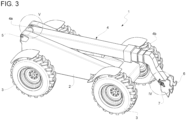
Figure 3 is a perspective view of a work vehicle comprising a control system according to the invention; -
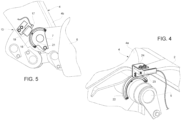
Figure 4 is a schematic enlarged representation of portion IV of the work vehicle; -
Figure 5 is a schematic enlarged representation of portion V of the work vehicle; -
Figure 6 is a schematic diagram block of the control system of the work vehicle; -
Figures 7-7A-7B-7C are a schematic diagram block showing the steps of the processes of the control method according to the invention; and -
Figure 8 is a schematic diagram block of the control method of the work vehicle. -
Figure 2 discloses awork vehicle 1, in the following simply referred as "telehandler" 1, comprising abody 2 that is movable on ground e.g. bywheels 3. - The
telehandler 1 further comprises aboom 4 that is carried in a movable way by thebody 2, in particular by ahinge connection 5 realized with afirst extremity 4a of theboom 4. On asecond extremity 4b of theboom 4, thetelehandler 1 comprises attachment means 6 such as, in the disclosed figures, forks. - The attachment means 6 are carried by the
second extremity 4b in a movable manner, in particular by ahinge connection 7. - The
telehandler 1 further comprises a first cylinder 8, in the following called lift cylinder, configured to actuate the rotation of theboom 4 with respect tohinge connection 5 by varying its length between a first connection point carried by theboom 4 and a second connection point carried bybody 2. - The
telehandler 1 further comprises a second cylinder 9, in the following called tilt cylinder, configured to actuate the rotation of the attachment 6 with respect tohinge connection 7 by varying its length between a first connection point carried by theboom 4 and a second connection point carried by attachment 6. - The
telehandler 1 further comprises a control system 10 for controlling the actuation of lift and tilt cylinder 8, 9 in function of the driver's need. - In particular, driver's need may be acquired by input means 11 such as a joystick that can be handled by the driver to provide a corresponding movement of the boom/attachment or by activating (e.g. by button or icon or a display) a specific automatic function.
- The control system 10 (see schematic representation in
figure 6 ) essentially comprises first sensor means 12, second sensor means 13 and anelectronic control unit 14 configured to receive data from the first and second sensor means 12, 13 and control consequently the lift and tilt cylinder 8, 9. - In particular, first and second sensor means 12, 13 are position sensor voted to detect an angular position of, respectively,
boom 4 and attachment 6 with respect thebase 2 and theboom 4. Preferably, first and second sensor means 12, 13 are magnetic sensor means. - In detail, (
figure 5 ) the second sensor means 13 comprises at least amagnet 16, fixedly carried by attachment 6 ad asensor 17 fixedly carried by thesecond portion 4b ofboom 4 in proximity ofmagnet 16. - Preferably,
sensor 17 is carried in ad adjustable manner bysecond portion 4b and more preferably via amounting bracket 19. - Advantageously, the
magnet 16 is carried by ametallic cover 21 dimensioned to at least partially surroundmagnet 16 in order to avoid damages due to hurt with transported loads by the attachment 6. - Similarly, (
figure 4 ) the first sensor means 12 comprises at least amagnet 22, fixedly carried by attachment boom ad a sensor 23 fixedly carried by thefirst portion 4a ofboom 4 in proximity ofmagnet 16. - Preferably, sensor 23 is carried in ad adjustable manner by
first portion 4a and more preferably via amounting bracket 24. - Advantageously, the
magnet 22 is carried by thefirst portion 4a directly in the boom main hub. - Making again reference to
figure 4 , theelectronic control unit 14 comprises elaboration means suitable for retrieving data from sensor means 12, 13, e.g. by cable connection or wireless, and provide an electronic control signal for controlling valve means 25. Such valve means 25 are configured to regulate the fluid passage between a fluid source and reservoir of thetelehandler 1 and cylinders 8, 9. - In particular, the electronic control unit is voted to run steps of a control method finalized to maintain the orientation of the attachment 6 constant during boom lifting or lowering.
- Making reference to
figures 7A-7B-7C and8 , such control method comprises the following processes: - i) Receive an input signal by input means 11 setting a desired height of the
telehandler 1, i.e. enabling the lifting/lowering function; - ii) Provide an output signal to valve means 25 that is function of the input signal received at process i); and
- iii) Proceed with a fine tuning of the height of the
telehandler 1 with respect to the height reached via output signal provided at process ii). - The processes may be executed in series or in parallel (e.g. in so-called concurrency one with respect to the other) .
- In detail, if the input means are preferably realized via a joystick, process i) comprise the following steps:
- i-a) detecting an imparted position y, x of the joystick with respect to a reference system;
- i-b) evaluating if the imparted position y, x of joystick along a first direction is greater with respect a pre-set threshold value y', in positive case proceed with the further step and in negative case return to step i-a);
- i-c) evaluating if the imparted position x of joystick along a second direction is lower than a preset threshold, in positive case a function is set to "enabled" and, possibly, proceed with process ii), in negative case return to step i-a).
- In particular, the enabling may be realized by by setting to 1 a specific RAM variable in the controller.
- Afterwards, the process restart by monitoring the joystick position in order to understand when it shall disable the function (i.e. set to 0 the aforementioned RAM variable).
- In such case, the process further comprises the following steps:
- i-d) detecting an imparted position y, x of the joystick with respect to a reference system;
- i-e) evaluating if the imparted position y of joystick along a first direction is lower with respect the aforementioned pre-set threshold value y', in positive case proceed with the further step and in negative case return to step i-d);
- i-f) evaluating if the imparted position x of joystick along a second direction is greater than a preset threshold, in positive case proceed set as "disable" the aforementioned function and return to step i-a) and in negative case return to step i-d).
- As in the precedent case, the disabling of function may be acquired to set the RAM variable to 0 .
- In particular, the reference system may be a cartesian plane wherein the origin of the cartesian plane is given by neutral joystick position and the first and second directions are y and x axis directions.
- The second process ii) is a feed forward phase and is carried out when the aforementioned process enables the function and comprise essentially the following steps:
- ii-a) acquiring the speed of the engine of the vehicle;
- ii-b) acquiring the aforementioned position y on the first direction;
- ii-c) associating to the aforementioned acquired data to a control current value I;
- ii-d) providing the aforementioned control current value I to valve means 25.
- In particular the association at step ii-a) may be an association obtained by an association map or a look-up table relating the engine speed and the joystick position to provide a value of control current.
- In particular, the control current value I is dimensioned so as do be greater than the dead band value of the valves comprised in valve means 25 in order to avoid slow activation of the system.
- In case the first process i) disables the function, the second process ii) provides a null value of control current.
- The third process iii) is a fine tuning process of the current I provided as control current and is activated if the function is enabled and comprise essentially the following steps:
- iii-a) initializing the value of control current for controlling valve means 25 to 0;
- iii-b) acquiring data from boom and attachment sensor means 12, 13;
- iii-c) if the controller is running the third process for the first time, then maintain as a variable r equals to the algebraic sum of data acquired boom and attach sensor means 12,13. Otherwise, it calculates the real error value z as difference of the position retrieved by sensor means 12, 13 and the reference r obtained previously;
- iii-d) evaluating the sign of first error value z in order to select a rollback or a dumping digital twin model of the
vehicle 1; - iii-e) elaborated according to the selected digital twin model a virtual value of the position according to the current control value obtained at the end of process ii);
- iii-f) calculate a second, theoretical, error b as difference of virtual value of position calculated at step iii-e) and the one imparted as reference r;
- iii-g) algebraically sum first and second errors z, b and provide such summed value to a regulator to calculate a new current value I';
- iii-h) algebraically sum the new current value I' to the control current value I provided at step ii-d) and;
- iii-i) providing to summed control current to the valve means 25.
- In particular, the aforementioned regulator is a robust optimal base approach, such as a linear quadratic gaussian regulator.
- The digital twin model of the
telehandler 1 may be a black-box model, such as a least square approximation of input-output transfer function. Such black-box model, memorized in electronic control unit, may be trained via provision of different control signals to valve means 25 (e.g sine, asymmetric/symmetric chirp, squared waveforms, random white noise) and control the angle variation of due to cylinders 8, 9 motions. - It is noticed that is a tilt operation or other similar automatic operations are required by the driver, the aforementioned control method is inhibited.
- The operation of the embodiment of the invention as described above is the following.
- The driver may control the input means 11 to ask a lifting or lowering of
boom 3. Accordingly, theelectronic control unit 14 will start control method steps described above and provide lifting and raising of the boom maintaining the attachment 6 in a fixed position, i.e. in a parallel position with respect to the ground. - In view of the foregoing, the advantages of a work vehicle and a related control method according to the invention are apparent.
- The proposed system and the related control has a lower costs because of the absence of a third cylinder and because there is no need to provide support to the additional load supported by the vehicle due to such third cylinder.
- Moreover, the boom-drop phenomenon is avoided Since the physical connection among cylinders is not present tanks to the proposed control.
- Since a part of the control is made via a feed-forward control, even in case of fault of sensor means, the control system may allow motion of the boom/attachment with a sufficient precision.
- The provided control method is rapid, robust and precise. Indeed, it allows to have a quick response by avoiding the dead band of valve means thanks to the feedforward initial control step and thanks to the regulator the precision is guaranteed within 3° of error with respect to the imparted position.
- Moreover, the provided control allows to maintain a specific angle of the attachment with respect to the boom during all the lifting/lowering of these latter, independently by the value of such angle. Therefore, telehandlers may be used also for buckets for transporting loads instead of forks.
- Even in case of change of attachment and of kinematic will not impart on the hardware, it could be only necessary to adapt the association map and the vehicle theoretical model to take into account such changes. Therefore the proposed control system is particularly versatile.
- It is furthermore noticed that the proposed mounting brackets provide a sufficient air requirement, i.e. the gap between the magnet and the sensor such as 3 mm, to allow a correct operation of sensor means.
- It is clear that modifications can be made to the described work vehicle and related control method which do not extend beyond the scope of protection defined by the claims.
- For example, sensor means may be of any typology and disposed in a different manner with respect to the disclosed one.
- In particular, the provided regulator, map and look-up tables or theoretical vehicle model may be realized according to the specific vehicle shape and function and of any typology.
Claims (18)
- Work vehicle (1) comprising a body (2) movable on ground and provided with a boom (4) carried by a first hinge connection (5) with respect to said body (2) and an attachment (6) carried by a second hinge connection (7) by said boom (4), said boom (4) being actuated by a first hydraulic cylinder (8) to move about said first hinge connection (5) and said attachment (6) being actuated by a second hydraulic cylinder (9) to move about said second hinge connection (7), said work vehicle (1) comprising a control system (10) comprising sensor means (12, 13) configured to detect a movement of said boom (4) and said attachment (6) with respect to respectively said body (2) and said boom (4) and an electronic control unit (14) comprising elaboration means configured to retrieve data from said sensor means (12, 13) and an input signal provided by the driver of said vehicle, elaborate these latter and provide a control signal to valve means (25) to control the operation of said first and second hydraulic cylinders (8, 9) to allow a lifting and lowering of said boom (4) while maintain the position of said attachment (6) fixed.
- Work vehicle according to claim 1, wherein said sensor means (12, 13) are angular sensor means.
- Work vehicle according to claim 1 or 2, wherein said sensor means (12, 13) are magnetic sensor means.
- Work vehicle according to any of claims 1 to 3, wherein said first sensor means (12) comprises a magnet (22) carried by said boom (4) and a magnetic sensor (23) carried by a bracket (24) fixedly secured to said body (2).
- Work vehicle according to any of claims 1 to 4, wherein said second sensor means (13) comprises a magnet (16) carried by said attachment (6) and a magnetic sensor (17) carried by a bracket (19) fixedly secured to said boom (4).
- Work vehicle according to claim 4 or 5, wherein said magnetic sensor (23, 17) is carried in an adjustable manner by said bracket (24, 19).
- Work vehicle according to claim 5, wherein said magnet (16) is carried by a cover (21) fixedly secured to said boom (4) and configured to entirely surround said magnet (16) from one side thereof.
- Method for controlling a first and a second hydraulic cylinders (8, 9) of a vehicle as claimed in any of claims 1 to 7 for providing a lifting/lowering function maintaining the position of said attachment fixed, said method comprising the following processes:i) Receive an input signal by input means (11) setting a desired height of the work vehicle (1);ii) Provide an output signal to valve means (25) that is function of the input signal received at process ii); andiii) Proceed with a fine tuning of the height of the work vehicle (1) with respect to the height reached via output signal provided at process iii),wherein said processes i-iii) may be executed in series or independently one with respect to the other.
- Method according to claim 8, wherein said input means (11) comprise a joystick and said process i) comprises the following steps:- i-a) detecting an imparted position (y, x) of the joystick with respect to a reference system;- i-b) evaluating if the imparted position (y) of joystick along a first direction is greater with respect a pre-set threshold value (y'), in positive case proceed with the further step and in negative case return to step i-a);- i-c) evaluating if the imparted position (x) of joystick along a second direction is lower than a preset threshold, in positive case set as "enabled" a lifting/lowering function, in negative case return to step i-a).
- Method according to claim 9, wherein, once the lifting/lowering function is enabled, the process further comprises the following steps:- i-d) detecting an imparted position (y, x) of the joystick with respect to a reference system;- i-e) evaluating if the imparted position (y) of joystick along a first direction is lower with respect the aforementioned pre-set threshold value (y'), in positive case proceed with the further step and in negative case return to step i-d);- i-f) evaluating if the imparted position (x) of joystick along a second direction is greater than a preset threshold, in positive case set as "disabled" said lifting/lowering function and return to step i-a), in negative case return to step i-d).
- Method according to any of claims 9 or 10, wherein said reference system is a cartesian plane wherein the origin of the cartesian plane is given by neutral joystick position and the first and second directions are (y) and (x) axis directions.
- Method according to any of claims 8 to 11, wherein the second process ii) is a feed forward process and comprise the following steps:- ii-a) acquiring the speed of the engine of the vehicle;- ii-b) acquiring the aforementioned position (y) on the first direction;- ii-c) associating to the aforementioned acquired data to a control current value (I);- ii-d) providing the aforementioned control current value I to valve means (25).
- Method according to claim 12, wherein the association at step ii-a) is an association obtained by an association map or a look-up table, wherein the current is function of the value of imparted position (Y) along first direction (y) and the speed of the engine of work vehicle (1) .
- Method according to claim 12 or 13, said control current value (I) is dimensioned so as to be greater than the dead band value of the valves comprised in valve means (25).
- Method according to any of claims 8 to 14, wherein the third process iii) is a fine tuning process and comprise the following steps:- iii-a) setting a control current for controlling valve means (25) as 0;- iii-b) acquiring data from boom and attachment sensor means (12, 13);- iii-c) if the third process is running for the first time, then maintain as variable (r) equal to algebraic sum of data acquired by sensor means (12, 13). Otherwise, calculate a first, real, error value z as difference of the position retrieved by sensor means (12, 13) and the aforementioned variable (r));- iii-d) evaluating the sign of first error value (z) in order to select a rollback or a dumping digital twin model of the vehicle (1);- iii-e) elaborated according to the selected digital twin model a virtual value of the position according to the current control value obtained at the end of process ii);- iii-f) calculate a second, theoretical, error (b) as difference of virtual value of position calculated at step iii-e);- iii-g) algebraically sum first and second errors (z, b) and provide such summed value to a regulator to calculate a new current value (i');- iii-h) algebraically sum the new current value (I') to the control current value (I) provided at step ii-d) and;- iii-i) providing to summed control current to the valve means (25).
- Method according to claim 15, wherein said regulator is a robust optimal base approach.
- Method according to claim 15 or 16, wherein said regulator is a linear quadratic gaussian regulator.
- Method according to any of claims 15 to 17 wherein said theoretical model of said work vehicle (1) is a black-box model based on a least square approximation of input-output transfer function.
Applications Claiming Priority (1)
| Application Number | Priority Date | Filing Date | Title |
|---|---|---|---|
| IT202200018717 | 2022-09-13 |
Publications (1)
| Publication Number | Publication Date |
|---|---|
| EP4339150A1 true EP4339150A1 (en) | 2024-03-20 |
Family
ID=84331147
Family Applications (1)
| Application Number | Title | Priority Date | Filing Date |
|---|---|---|---|
| EP23195521.2A Pending EP4339150A1 (en) | 2022-09-13 | 2023-09-05 | Improved telehandler and related control method |
Country Status (1)
| Country | Link |
|---|---|
| EP (1) | EP4339150A1 (en) |
Citations (5)
| Publication number | Priority date | Publication date | Assignee | Title |
|---|---|---|---|---|
| EP1403526A1 (en) * | 2002-09-25 | 2004-03-31 | Husco International, Inc. | Method of selecting a hydraulic metering mode for a function of a velocity based control system |
| EP1988220A2 (en) * | 2007-04-30 | 2008-11-05 | Deere & Company | Automated control of boom or attachment for work vehicle to a preset position |
| US8340875B1 (en) * | 2011-06-16 | 2012-12-25 | Caterpillar Inc. | Lift system implementing velocity-based feedforward control |
| CN105804138B (en) * | 2016-05-12 | 2018-09-25 | 宁波高新区晖云电子科技有限公司 | A kind of angle measurement method for building machinery |
| US10781090B2 (en) * | 2017-09-01 | 2020-09-22 | Oshkosh Corporation | Articulated boom telehandler |
-
2023
- 2023-09-05 EP EP23195521.2A patent/EP4339150A1/en active Pending
Patent Citations (5)
| Publication number | Priority date | Publication date | Assignee | Title |
|---|---|---|---|---|
| EP1403526A1 (en) * | 2002-09-25 | 2004-03-31 | Husco International, Inc. | Method of selecting a hydraulic metering mode for a function of a velocity based control system |
| EP1988220A2 (en) * | 2007-04-30 | 2008-11-05 | Deere & Company | Automated control of boom or attachment for work vehicle to a preset position |
| US8340875B1 (en) * | 2011-06-16 | 2012-12-25 | Caterpillar Inc. | Lift system implementing velocity-based feedforward control |
| CN105804138B (en) * | 2016-05-12 | 2018-09-25 | 宁波高新区晖云电子科技有限公司 | A kind of angle measurement method for building machinery |
| US10781090B2 (en) * | 2017-09-01 | 2020-09-22 | Oshkosh Corporation | Articulated boom telehandler |
Non-Patent Citations (2)
| Title |
|---|
| BING HONG XU ET AL: "Adaptive neural regulator and its application to torque control of a flexible beam", INTELLIGENT ROBOTS AND SYSTEMS '96, IROS 96, PROCEEDINGS OF THE 1996 L EEE/RSJ INTERNATIONAL CONFERENCE ON OSAKA, JAPAN 4-8 NOV. 1996, NEW YORK, NY, USA,IEEE, US, vol. 1, 4 November 1996 (1996-11-04), pages 230 - 237, XP010212384, ISBN: 978-0-7803-3213-3, DOI: 10.1109/IROS.1996.570678 * |
| HOLE K E: "Design of Robust Linear Quadratic Regulator", AMERICAN CONTROL CONFERENCE, 1989, IEEE, PISCATAWAY, NJ, USA, 21 June 1989 (1989-06-21), pages 929 - 930, XP031428984 * |
Similar Documents
| Publication | Publication Date | Title |
|---|---|---|
| EP3128084B1 (en) | Work vehicle with improved implement position control and self-leveling functionality | |
| US5899008A (en) | Method and apparatus for controlling an implement of a work machine | |
| EP2947209B1 (en) | Improved lift assembly for a work vehicle | |
| US8974171B2 (en) | Work vehicle | |
| US8612103B2 (en) | Implement angle correction system and associated loader | |
| US5826666A (en) | Apparatus and method for controlling a contruction machine | |
| US5701793A (en) | Method and apparatus for controlling an implement of a work machine | |
| US10407282B2 (en) | Position control of a boom tip | |
| US5737993A (en) | Method and apparatus for controlling an implement of a work machine | |
| US7093383B2 (en) | Automatic hydraulic load leveling system for a work vehicle | |
| US8594896B2 (en) | Lift arm control system | |
| EP2924176B1 (en) | Front loader | |
| KR102248499B1 (en) | Hydraulic working machine | |
| EP2697441B1 (en) | Method and device for reducing vibrations in a working machine | |
| US6374153B1 (en) | Apparatus and method for providing coordinated control of a work implement | |
| US7845169B2 (en) | Drift compensation control method for a machine | |
| US10385541B2 (en) | Work vehicle with improved loader/implement return position control | |
| EP4339150A1 (en) | Improved telehandler and related control method | |
| JP2016125284A (en) | Construction machine | |
| JP4651907B2 (en) | Method for controlling the dead zone of a fluid system | |
| US20220090358A1 (en) | Hydraulic arrangement | |
| US20190211530A1 (en) | Construction Machine | |
| JPH05321302A (en) | Hydraulic shovel also useable as crane | |
| JP7280212B2 (en) | wheel loader | |
| EP4353913A1 (en) | Control and command assembly for a lifting arm of an operating machine |
Legal Events
| Date | Code | Title | Description |
|---|---|---|---|
| PUAI | Public reference made under article 153(3) epc to a published international application that has entered the european phase |
Free format text: ORIGINAL CODE: 0009012 |
|
| STAA | Information on the status of an ep patent application or granted ep patent |
Free format text: STATUS: THE APPLICATION HAS BEEN PUBLISHED |
|
| AK | Designated contracting states |
Kind code of ref document: A1 Designated state(s): AL AT BE BG CH CY CZ DE DK EE ES FI FR GB GR HR HU IE IS IT LI LT LU LV MC ME MK MT NL NO PL PT RO RS SE SI SK SM TR |