EP4338772A2 - Reusable medication delivery device with remaining medication determination capability - Google Patents
Reusable medication delivery device with remaining medication determination capability Download PDFInfo
- Publication number
- EP4338772A2 EP4338772A2 EP24155471.6A EP24155471A EP4338772A2 EP 4338772 A2 EP4338772 A2 EP 4338772A2 EP 24155471 A EP24155471 A EP 24155471A EP 4338772 A2 EP4338772 A2 EP 4338772A2
- Authority
- EP
- European Patent Office
- Prior art keywords
- cartridge
- sensor
- drive member
- medication
- delivery device
- Prior art date
- Legal status (The legal status is an assumption and is not a legal conclusion. Google has not performed a legal analysis and makes no representation as to the accuracy of the status listed.)
- Pending
Links
- 239000003814 drug Substances 0.000 title claims abstract description 161
- 229940079593 drug Drugs 0.000 title claims abstract description 161
- 230000007246 mechanism Effects 0.000 claims abstract description 26
- 238000004891 communication Methods 0.000 claims description 10
- 238000002347 injection Methods 0.000 description 20
- 239000007924 injection Substances 0.000 description 20
- 230000008859 change Effects 0.000 description 6
- 230000003287 optical effect Effects 0.000 description 5
- 230000007704 transition Effects 0.000 description 5
- 230000001960 triggered effect Effects 0.000 description 4
- 230000008901 benefit Effects 0.000 description 3
- 238000010276 construction Methods 0.000 description 3
- 230000033001 locomotion Effects 0.000 description 3
- 230000006978 adaptation Effects 0.000 description 2
- 238000005516 engineering process Methods 0.000 description 2
- 230000001939 inductive effect Effects 0.000 description 2
- 239000011248 coating agent Substances 0.000 description 1
- 238000000576 coating method Methods 0.000 description 1
- 230000000295 complement effect Effects 0.000 description 1
- 201000010099 disease Diseases 0.000 description 1
- 208000037265 diseases, disorders, signs and symptoms Diseases 0.000 description 1
- 230000003993 interaction Effects 0.000 description 1
- 239000007788 liquid Substances 0.000 description 1
- 230000007257 malfunction Effects 0.000 description 1
- 238000002483 medication Methods 0.000 description 1
- 238000012544 monitoring process Methods 0.000 description 1
- 238000002360 preparation method Methods 0.000 description 1
- 230000001681 protective effect Effects 0.000 description 1
Images


Classifications
-
- A—HUMAN NECESSITIES
- A61—MEDICAL OR VETERINARY SCIENCE; HYGIENE
- A61M—DEVICES FOR INTRODUCING MEDIA INTO, OR ONTO, THE BODY; DEVICES FOR TRANSDUCING BODY MEDIA OR FOR TAKING MEDIA FROM THE BODY; DEVICES FOR PRODUCING OR ENDING SLEEP OR STUPOR
- A61M5/00—Devices for bringing media into the body in a subcutaneous, intra-vascular or intramuscular way; Accessories therefor, e.g. filling or cleaning devices, arm-rests
- A61M5/178—Syringes
- A61M5/31—Details
- A61M5/315—Pistons; Piston-rods; Guiding, blocking or restricting the movement of the rod or piston; Appliances on the rod for facilitating dosing ; Dosing mechanisms
- A61M5/31565—Administration mechanisms, i.e. constructional features, modes of administering a dose
- A61M5/31566—Means improving security or handling thereof
- A61M5/31568—Means keeping track of the total dose administered, e.g. since the cartridge was inserted
-
- A—HUMAN NECESSITIES
- A61—MEDICAL OR VETERINARY SCIENCE; HYGIENE
- A61M—DEVICES FOR INTRODUCING MEDIA INTO, OR ONTO, THE BODY; DEVICES FOR TRANSDUCING BODY MEDIA OR FOR TAKING MEDIA FROM THE BODY; DEVICES FOR PRODUCING OR ENDING SLEEP OR STUPOR
- A61M5/00—Devices for bringing media into the body in a subcutaneous, intra-vascular or intramuscular way; Accessories therefor, e.g. filling or cleaning devices, arm-rests
- A61M5/178—Syringes
- A61M5/24—Ampoule syringes, i.e. syringes with needle for use in combination with replaceable ampoules or carpules, e.g. automatic
-
- A—HUMAN NECESSITIES
- A61—MEDICAL OR VETERINARY SCIENCE; HYGIENE
- A61M—DEVICES FOR INTRODUCING MEDIA INTO, OR ONTO, THE BODY; DEVICES FOR TRANSDUCING BODY MEDIA OR FOR TAKING MEDIA FROM THE BODY; DEVICES FOR PRODUCING OR ENDING SLEEP OR STUPOR
- A61M5/00—Devices for bringing media into the body in a subcutaneous, intra-vascular or intramuscular way; Accessories therefor, e.g. filling or cleaning devices, arm-rests
- A61M5/178—Syringes
- A61M5/31—Details
- A61M5/315—Pistons; Piston-rods; Guiding, blocking or restricting the movement of the rod or piston; Appliances on the rod for facilitating dosing ; Dosing mechanisms
- A61M5/31533—Dosing mechanisms, i.e. setting a dose
- A61M5/31545—Setting modes for dosing
- A61M5/31548—Mechanically operated dose setting member
- A61M5/3155—Mechanically operated dose setting member by rotational movement of dose setting member, e.g. during setting or filling of a syringe
- A61M5/31551—Mechanically operated dose setting member by rotational movement of dose setting member, e.g. during setting or filling of a syringe including axial movement of dose setting member
-
- A—HUMAN NECESSITIES
- A61—MEDICAL OR VETERINARY SCIENCE; HYGIENE
- A61M—DEVICES FOR INTRODUCING MEDIA INTO, OR ONTO, THE BODY; DEVICES FOR TRANSDUCING BODY MEDIA OR FOR TAKING MEDIA FROM THE BODY; DEVICES FOR PRODUCING OR ENDING SLEEP OR STUPOR
- A61M5/00—Devices for bringing media into the body in a subcutaneous, intra-vascular or intramuscular way; Accessories therefor, e.g. filling or cleaning devices, arm-rests
- A61M5/178—Syringes
- A61M5/31—Details
- A61M5/315—Pistons; Piston-rods; Guiding, blocking or restricting the movement of the rod or piston; Appliances on the rod for facilitating dosing ; Dosing mechanisms
- A61M5/31533—Dosing mechanisms, i.e. setting a dose
- A61M5/31535—Means improving security or handling thereof, e.g. blocking means, means preventing insufficient dosing, means allowing correction of overset dose
- A61M5/31543—Means improving security or handling thereof, e.g. blocking means, means preventing insufficient dosing, means allowing correction of overset dose piston rod reset means, i.e. means for causing or facilitating retraction of piston rod to its starting position during cartridge change
Definitions
- the present invention pertains to medication delivery devices, and, in particular, to medication delivery devices that are reusable with replacement cartridges.
- a reusable injection pen Such an injection pen is typically equipped with a cartridge including a plunger and containing a multi-dose quantity of liquid medication. A drive member of the pen is movable forward by a dose delivery mechanism to advance the plunger in the cartridge in such a manner to dispense the contained medication through a needle that penetrates a septum at a forward end of the cartridge. After such a pen has been utilized to deliver multiple doses and exhaust the supply of medication within the cartridge, a user can remove and dispose of the spent cartridge. After a user installs a replacement cartridge, the reusable injection pen then can be used again to deliver its medication contents in a conventional manner.
- At least one known reusable injection pen utilizes an electronics assembly to determine a set and injected dose by monitoring relative motions of components used in setting a dose, and components used in advancing a drive screw to inject the set dose, respectively. While useful, one shortcoming of this pen is that it provides no mechanism to track the amount of medication remaining in a cartridge. While medication delivery device designs are known that can track drive screw position sufficiently accurately throughout its operational travel path, which would allow drive screw travel remaining and thereby medication remaining to be determined, such designs may add complexity to the device.
- the present invention provides a reusable medication delivery device for delivering medication from a cartridge having a barrel holding the medication between a movable plunger and an outlet.
- the reusable medication delivery device includes: a main housing; a cartridge housing adapted to removably receive the cartridge, the cartridge housing detachably mountable to the main housing; a drive member including a forward end for engaging the movable plunger, the drive member having a length extending in an axial direction within the main housing and including a sensible element along a portion of the length; a dose delivery mechanism for controlling advancement of the drive member forward within the main housing in the axial direction from a rearward position to a forward position, wherein advancement of the drive member forward in the axial direction, when the cartridge housing receives the cartridge and is mounted to the main housing, moves the movable plunger for delivering medication through the outlet; means for determining an amount of medication delivered by operation of the dose delivery mechanism; a first sensor for sensing either when the cartridge housing is mounted to the main housing or a presence of the
- the present invention provides a reusable medication delivery device for delivering medication from a cartridge assembly having a barrel holding the medication between a movable plunger and an outlet, the cartridge assembly including a first mounting element.
- the reusable medication delivery device includes: a main housing including a second mounting element cooperatively configured with the first mounting element for a detachable mounting of the cartridge assembly to the main housing; a drive member including a forward end for engaging the movable plunger, the drive member having a length extending in an axial direction within the main housing and including a sensible element along a portion of the length; a dose delivery mechanism for controlling advancement of the drive member forward within the main housing in the axial direction from a rearward position to a forward position, wherein advancement of the drive member forward in the axial direction, when the cartridge assembly is mounted to the main housing, moves the movable plunger for delivering medication through the outlet; means for determining an amount of medication delivered by operation of the dose delivery mechanism; a first sensor for sensing when the cartridge assembly is mounted to the main housing
- One advantage of the present invention is that a reusable medication delivery device can be provided with a simple means to determine when a full cartridge is installed therein.
- Another advantage of the present invention is that a reusable medication delivery device can be provided with the ability to track medication remaining in a ready fashion.
- a reusable medication delivery device equipped with a sensing system that allows a determination of medication remaining after first recognizing as full a medication cartridge when newly installed in the device.
- the device is a reusable pen-shaped medication injection device, generally designated 100, which is manually handled by a user to selectively set a dose and then to inject that set dose.
- Injection devices of this type are well known, and the description of device 100 is merely illustrative as the sensing system can be adapted for use in variously constructed pen-shaped medication injection devices, as well as differently shaped injection devices and other medication delivery devices in general.
- Medication injection device 100 includes a housing that supports the internal components of the device.
- the housing is shown as having a rear or main housing 102 and a forward or cartridge housing 104.
- Main housing 102 holds a mechanical drive mechanism of the device.
- Cartridge housing 104 also known as the cartridge retainer, holds a cartridge 106 filled with medication to be delivered by device operation.
- Cartridge retainer 104 is detachably mountable to main housing 102 via external threading 110 on a protruding collar portion 112 of main housing 102 which mates with internal threading 114 on a ring portion 116 at the proximal end of cartridge retainer 104.
- Suitable detachable mounting elements other than threadings 110 and 114 are known in the art and naturally may be employed, such as a bayonet fitting, or the use of an additional latching component.
- Cartridge retainer 104 includes an internal hollow 105 suited to removably receive cartridge 106, thereby allowing a cartridge to be inserted therein, and then removed therefrom when depleted and replaced with a fresh cartridge of similar design. Openings 118 in cartridge retainer 104 allow visibility of the cartridge contents.
- a detent feature 120 provided on the exterior of cartridge retainer 104 allows for a not shown protective cap to be detachably mounted over the cartridge retainer 104 when a needle assembly 125 is not attached to the cartridge retainer 104.
- cartridge retainer 104 is described herein as being a reusable component, the cartridge retainer 104 could be integrated with, and therefore be disposable with, the cartridge 106.
- Medication cartridge 106 is of conventional design, including a barrel 130 having an interior reservoir filled with medication which is sealed at one end by a slidable plunger or piston 132 and sealed at the other end by a septum 134 held by a crimp ring 136.
- the pierced septum through which the needle extends serves as an outlet during dispensing for the medication within the reservoir of barrel 130, which medication is delivered through the needle assembly 125 by operation of device 100.
- the cartridge 106 can hold multiple doses of medication, or even a single dose, depending on the purpose of device 100.
- Medication injection device 100 is shown in Fig. 1 in its "zero position" at which the device has not been set for delivery of any dose. This zero position setting is indicated by the number “0" visible on the dose display 140 in Fig. 1 .
- device 100 is arranged after being manipulated to set a dose of thirty units for delivery, and the number "30" would be visible on the display 140.
- Medication injection device 100 is typical of many such reusable devices in including a manually-powered dose delivery mechanism, generally designated 150, that controls forward advancement of a drive member, generally designated 160.
- Drive member 160 advances within the cartridge barrel 130 to directly engage and advance plunger 132.
- dose delivery mechanism 150 includes a dose knob 152 connected via a tube 154 to a mechanical drive assembly abstractly indicated at 156 that is housed within main housing 102. When knob 152 is turned by a user to set a dose for injection, dose knob 152 and tube 154 screw out together from main housing 102.
- dose knob 152 When a user applies a plunging force on the proximal end 158 of dose knob 152, the resulting simply translational motion of dose knob 152 and tube 154 forward into main housing 102 is converted by drive assembly 156 into a smaller motion of drive member 160 forward from main housing 102 into the interior of cartridge barrel 130.
- Drive member 160 is formed in two pieces including a forward end 163 that directly engages the cartridge plunger 132, and a shaft 165 that axially extends rearward from forward end 163 into main housing 102.
- the shaft 165 is threaded at 167 and is engaged with drive assembly 156 to be screwed out from main housing 102 as it is driven forward.
- Forward end 163 is provided in the form of an enlarged foot that is mounted on shaft 165 to allow relative rotation, allowing foot 163 to engage plunger 132 without relative rotation therebetween as shaft 165 screws out.
- drive member 160 While this foot and shaft two-piece construction of drive member 160 is preferred when shaft 165 screws out from the housing during advancement, such a construction is not required in devices, particularly if the drive member simply translates within the housing, in which case a single piece drive member construction may be more acceptable.
- Device 100 uses an electronic dose display 140 rather than a helically marked dial display as used in many other reusable injection devices.
- Display 140 is circuited to and controlled by an electronic controller or computing assembly 170 mounted within main housing 102.
- Controller 170 is programmed and has memory sufficient to achieve the electronic features of device 100.
- the set dose displayed in display 140 is determined by the interaction of dose delivery mechanism 150 with a sensor mechanism or system, abstractly shown at 175, which is circuited with and controlled by controller 170.
- a sensor mechanism 175 can be, for example, an electrical, magnetic, optical, audible, ultrasonic or other sensing technology as is known in the art.
- sensor mechanism 175 is equipped with a feature as is known in the art allowing the controller 170 to recognize when a set dose is in fact delivered, such sensor mechanism 175 can serve to determine the amount of medication delivered by dose delivery mechanism 150 when operated to deliver the set dose. Alternatively, other mechanisms to determine the amount of medication delivered by operation of dose delivery mechanism 150 may be used in device 100.
- Such an alternate mechanism includes a system that does not sense the amount of a set dose but merely senses, such as using electrical, magnetic, optical, audible, inductive or other sensing means as is known in the art, a delivered dose, including but not limited to a sensor mechanism that determines positions of, for example, a drive element before and after an injection to allow a dose delivery amount to be calculated by the controller based on the distance the drive element is sensed to have moved.
- device 100 is intended to be illustrative and not limiting as the sensing system that allows determination of medication remaining in a cartridge as described further below may be used in other differently configured devices.
- Device 100 is similar in many respects to a device described in International Publication Number WO 02/092153 , which publication is incorporated herein by reference in its entirety.
- the system for determining remaining medication uses both a sensor for sensing drive member 160, and a sensor for sensing the cartridge 106 and/or cartridge retainer 104.
- the drive member sensing sensor 190 is mounted within main housing 102 and circuited with and controlled by controller 170.
- Sensor 190 which may be composed of a single sensing element or an array of multiple sensing elements, serves to sense the sensible element, generally indicated at 194, of drive member 160.
- Sensor 190 is fixed within the length of main housing 102 in order to sense sensible element 194 to allow a determination of whether drive member 160 is pushed back from a fully advanced or forward position a distance needed to accommodate a new full cartridge.
- One possible positioning of sensor 190 within housing 102 is at a sensing point, or a point slightly forward of such point, where it is triggered by the sensible element 194 just as the forward end 163 of drive member 160 reaches an axial position at which it could be expected to abut or initially engage the proximal face of a plunger 132 in a full cartridge 106 that is within the fully assembled device 100.
- the axial position of the drive member 160 at such arrangement is known as the cartridge full retracted position, though it will be appreciated that variability due to tolerances of the device and the cartridges means the drive member 160 might be slightly differently so positioned within the housing from cartridge to cartridge. For example, some cartridges are nominally 300 unit cartridges.
- the sensor 190 may be positioned within main housing 102 at a position where it is triggered by sensing element 194 when the drive member 160 is retracted a distance corresponding to 295-300 units of delivery from the fully advanced forward position, where the 300 units of delivery position may be considered the cartridge full retracted position.
- the positioning of sensor 190 may be forward or rearward of these points, but preferably is not so far rearward within the main housing 102 that is might fail to recognize a drive member that is merely retracted sufficiently far for the smallest full cartridge within tolerances with which the device may be used.
- the drive member can be manually pushed back into the housing during device resetting a distance that is farther than required to accommodate a full cartridge within tolerances then loaded into the device for use. Having the sensor 190 be triggered only when the drive member 160 is pushed all the way back to its physical stop in such a device would lead to the device not recognizing some or possibly all cartridges that should be considered full.
- Sensor 190 may be positioned more forward of the sensing point than as described above if the possibility of false positive recognitions are acceptable, particularly if a checking feature as described further below is implemented.
- the sensor 190 may be positioned within main housing 102 at a position where it is triggered by sensing element 194 when the drive member 160 is retracted a distance corresponding to, for example, any of 250, 260, 270, 280 or 290 units of delivery from the fully advanced forward position, especially if positioning the sensor at, for example, 300 units would require the device to be unacceptably longer.
- sensor 190 can be positioned up to, for example, one-half, or a third, or a fourth, or a fifth of such total possible travel distance forward of such sensing point.
- One suitable type of sensor for sensor 190 is a magnet sensor that generates a signal that goes form a low amplitude to a high amplitude as the sensible element 194 passes by, or passes through a point at which transverse to the axial direction it is aligned with, sensor 190 when moving in the rearward or retraction direction.
- Such change in amplitude can be considered a switch triggering.
- the change from low amplitude to high amplitude is not instantaneous but rather has a transition slope during sensible element travel, with stronger magnets for sensible element 194 producing steeper transition slopes.
- the signal generated by sensor 190 tapers slowly in amplitude but continues to have a relatively high value.
- the signal generated by sensor 190 over the range of distances possible in device 100, rises slightly in amplitude but continues to have a relatively low value.
- the signal resolution is not sufficiently precise to allow a device controller to determine an exact axial position of the drive member 160 within the housing suitable to allow dose amounts, or delivery volume remaining, to be calculated.
- the relatively high amplitude of the output of sensor 190 when drive member 160 is retracted beyond a point of transverse alignment with sensor 190 allows the controller to recognize the drive member as being retracted within a range of positions rearward of the aligned position. This allows a sensing of an over retraction of drive member 160, such as if a user, while device 100 was disassembled and in preparation of loading a replacement cartridge 106, manually pushes the drive member 160 rearward into the main housing 102 farther than is needed to prepare for a new full cartridge.
- the controller can be programmed to consider a signal amplitude found within the signal transition period to be the point at which it considers alignment to have occurred, and the high amplitude and low amplitude outputs otherwise more typically produced by the sensor 190 would be readily recognized as occurring on opposite sides of such alignment point.
- sensible element 194 is abstractly shown as a discrete feature provided on drive member shaft 165 near the rearward end of that shaft.
- a suitable sensible element 194 may be a magnet with its opposite magnetic poles being on opposite axial ends of the sensible element.
- sensible element 194 could be another form of specialized element coordinated with a complementary sensor 190.
- sensible element 194 could be a reflective coating or a character that is readily sensed by an optical sensor 190.
- the sensible element 194 could be the rear end face of shaft 165 that contacts an electrical switch serving as sensor 190, or that otherwise may be sensed as being present or absent, such as by an optical sensor 190.
- Other sensing technologies that are known, such as inductive or ultrasonic, alternatively may be used.
- sensible element 194 is shown fixed in the rear end of shaft 165, such a positioning is a not required to practice the present invention but is preferred. In the shown embodiment, in which controller 170 is located within the rearward portion of housing 102, such a positioning of sensible element 194 is useful as sensor 190 can be positioned within the rearward portion of housing 102 and the length of the electrical connection between sensor 190 and controller 170, be it via spanning wiring or otherwise such as a conductive track on a printed circuit board, is short. Sensible element 194 could be otherwise provided along the length of shaft 165, such as in the middle or near the forward end of the shaft 165, if a corresponding positional change of sensor 190 within housing 102 were made.
- the sensor for sensing the cartridge 106 is shown at 200 in Fig. 2 .
- Sensor 200 is mounted within housing 102 and circuited with controller 170.
- Sensor 200 is constructed to sense the presence or absence of a cartridge 106 when housing portions 102 and 104 are operationally assembled for device use.
- Different types of sensors may be used for sensor 200, with appropriate adaptation of cartridge 106 if needed, such as an electrical switch or a magnetic or optical sensor.
- sensor 200 can indirectly sense the cartridge presence, such as by sensing the position of a device component, such as a drive member-engaging nut, which is moved by contact with a cartridge installed when the housing portions 102 and 104 are assembled for use.
- sensor 200 could be positioned to sense the presence of absence of cartridge retainer 104 operationally assembled to housing 102. As with sensing of the cartridge described above, such retainer sensing could be done either directly or indirectly. In a retainer sensing scenario, the user would be required to ensure that a cartridge was loaded within that retainer 104 in order for the remaining dose information that can be provided by device 100 as described below to be of any value. In a scenario where the cartridge and retainer were integrated by the manufacturer to be handled as a single cartridge assembly that is disposable as a unit after the cartridge contents are exhausted, the sensor 200 could be adapted to sense the presence of absence of the cartridge assembly mounted to housing 102, again either directly or indirectly.
- Sensors 200 and 190 are utilized by controller 170 to determine when a new, full cartridge has been loaded into device 100, so that remaining medication in that cartridge can be tracked thereafter. Controller 170 continuously monitors the signal from sensor 200. When the signal from sensor 200 changes from one associated with no cartridge sensed as present to one associated with a cartridge 106 being sensed as present, controller 170 understands or recognizes that device 100 has been assembled with a cartridge 106 loaded within cartridge retainer 104.
- controller 170 When a cartridge 106 is so recognized as present, controller 170 considers the signal from sensor 190. If the signal that sensor 190 sends to controller 170 is recognized by controller 170 as drive member 160 of device 100 being in a position at which the sensible element 194 is aligned with, or rearward of, the sensor 190, the controller 170 associates this combination of signals from sensors 200 and 190 as a newly loaded cartridge 106 being a full cartridge. Such a full cartridge status can be shown on display 140, or a display on a device with which controller 170 is linked.
- Controller 170 can then keep track of medication remaining in the cartridge 106 throughout the use of device 100 until controller 170 recognizes, due to a change in signal from sensor 200, that cartridge 106 is no longer present. Such tracking is performed by controller 170 subtracting, from the original quantity the controller is programmed to expect in a full cartridge, amounts that the device 100 is sensed as subsequently dispensing during one or more operations, such as by tracking the information provided by sensor system 175 during injecting operations.
- the amount calculated by controller 170 to be remaining in the cartridge 106 at any given time can be displayed in display 140, or a display of a smart device such as a phone if the device 100 is linked to it. The user may be notified on such a display of the remaining volume at different times, such as after each dispensing or whenever the pen is turned or when the user manipulates the pen or smart device to query the controller 170 as to the medication remaining.
- sensor 190 is positioned forward of where the sensible element is located when the drive member 160 is in a cartridge full retraction position, it is possible that a newly installed cartridge that the controller 170 believes to be full is not so.
- the device controller 170 can be programmed to perform checks during later use that identify such fact and then inform the user that remaining medication tracking is not possible for the loaded cartridge. For example, if the sensor 190 were positioned a distance corresponding to 250 units of delivery from the fully advanced forward position of the drive member, controller 170 would expect sensor 190 to identify, via a change in signal from high to low, sensible element 194 being aligned with the sensor 190 after approximately fifty units have delivered during normal use from the cartridge initially determined to be full.
- Controller 170 can be programmed to recognize that during subsequent device use, when input from sensor 190 is recognized by controller 170 as sensible element 194 having reached sensor 190 sooner than would have been expected had the installed cartridge been full, that a not full cartridge had been installed previously. For the above example, if a cartridge filled with 270 units had been newly installed, which cartridge would have been thought by controller 170 to have been full of 300 units, the fact that the sensor 190 will change its output after twenty units have been delivered, as opposed to fifty units as expected by the controller, will cause the controller 170 to recognize the prior error in believing the cartridge was full. The controller 170 will understand that the calculated quantity of medication remaining in the installed cartridge after medication delivery is not reliable in such a circumstance, and can send an appropriate message to the user in display 140, or other linked display, such as "medication remaining tracking no longer available for this cartridge".
- controller 170 can account for different concentrations of medication in cartridge 106, such as by working with a sensor of info about the concentration from the cartridge, or by a user inputting such info into device 100 either directly by device manipulation or via an electronic downloading of such information, such that the medication amount remaining, as well as dose set and injected, can be tracked as units and not volume.
- the controller may also track the actual time, or relative time of, cartridge changes, which can then be communicated wirelessly to an external device, such as a smartphone having an application that accepts and uses such data.
- the controller also may monitor device states that indicate errors or malfunctions that can be alerted on the display or wirelessly sent to a remote device, such as a smartphone.
- the user can disassemble retainer 104 from main housing 102 by unscrewing them apart. Such a disassembled state is shown in Fig. 4 .
- the signal sent by sensor 200 to controller 170 is recognized as cartridge 106 being no longer present in device 100.
- Display 140 can be controlled to indicate that no cartridge is present in the device 100.
- a user then can prepare the device 100 for future operation in the following manner. After removing the spent cartridge 106 from retainer 104 and inserting a replacement cartridge 106 in the retainer 104, the user can arrange the retainer 104 and main housing 102 such that the drive member forward end 163 is insertably aligned with the cartridge barrel 130, and then the retainer 104 and main housing 102 can be moved together axially and operationally secured, causing the drive member 160 to be driven rearward by the contact of forward end 163 with the rear face of cartridge plunger 132 . After such an assembling of retainer 104 with main housing 102, controller 170 will again recognize the presence of cartridge 106, due to the input from sensor 200.
- each device could be calibrated when manufactured to determine the output value of sensor 190, within the transitioning between relatively low and high signals, that best corresponds to the transverse alignment of the sensible element 194 with sensor 190, which output value when stored into the controller to use as a threshold value would provide even greater certainty in a device as to whether a cartridge was full when installed.
- This application is therefore intended to cover any variations, uses or adaptations of the invention using its general principles. Further, this application is intended to cover such departures from the present disclosure as come within known or customary practice in the art to which this invention pertains.
Landscapes
- Health & Medical Sciences (AREA)
- Vascular Medicine (AREA)
- Engineering & Computer Science (AREA)
- Anesthesiology (AREA)
- Biomedical Technology (AREA)
- Heart & Thoracic Surgery (AREA)
- Hematology (AREA)
- Life Sciences & Earth Sciences (AREA)
- Animal Behavior & Ethology (AREA)
- General Health & Medical Sciences (AREA)
- Public Health (AREA)
- Veterinary Medicine (AREA)
- Infusion, Injection, And Reservoir Apparatuses (AREA)
- Medical Preparation Storing Or Oral Administration Devices (AREA)
Abstract
Description
- The present invention pertains to medication delivery devices, and, in particular, to medication delivery devices that are reusable with replacement cartridges.
- Patients suffering from a number of different diseases frequently must inject themselves with medications. A variety of devices have been proposed to facilitate these injections. One known type of device is a reusable injection pen. Such an injection pen is typically equipped with a cartridge including a plunger and containing a multi-dose quantity of liquid medication. A drive member of the pen is movable forward by a dose delivery mechanism to advance the plunger in the cartridge in such a manner to dispense the contained medication through a needle that penetrates a septum at a forward end of the cartridge. After such a pen has been utilized to deliver multiple doses and exhaust the supply of medication within the cartridge, a user can remove and dispose of the spent cartridge. After a user installs a replacement cartridge, the reusable injection pen then can be used again to deliver its medication contents in a conventional manner.
- At least one known reusable injection pen utilizes an electronics assembly to determine a set and injected dose by monitoring relative motions of components used in setting a dose, and components used in advancing a drive screw to inject the set dose, respectively. While useful, one shortcoming of this pen is that it provides no mechanism to track the amount of medication remaining in a cartridge. While medication delivery device designs are known that can track drive screw position sufficiently accurately throughout its operational travel path, which would allow drive screw travel remaining and thereby medication remaining to be determined, such designs may add complexity to the device.
- Thus, it would be desirable to provide a reusable delivery device that can overcome one or more of these and other shortcomings of the prior art.
- In one form thereof, the present invention provides a reusable medication delivery device for delivering medication from a cartridge having a barrel holding the medication between a movable plunger and an outlet. The reusable medication delivery device includes: a main housing; a cartridge housing adapted to removably receive the cartridge, the cartridge housing detachably mountable to the main housing; a drive member including a forward end for engaging the movable plunger, the drive member having a length extending in an axial direction within the main housing and including a sensible element along a portion of the length; a dose delivery mechanism for controlling advancement of the drive member forward within the main housing in the axial direction from a rearward position to a forward position, wherein advancement of the drive member forward in the axial direction, when the cartridge housing receives the cartridge and is mounted to the main housing, moves the movable plunger for delivering medication through the outlet; means for determining an amount of medication delivered by operation of the dose delivery mechanism; a first sensor for sensing either when the cartridge housing is mounted to the main housing or a presence of the cartridge within the cartridge housing when the cartridge housing is mounted to the main housing; at least one second sensor for sensing the sensible element as being located at a position within the main housing which is associated with the drive member being retracted to at least a first retraction position axially rearward of the forward position; and a controller in communication with the first sensor and the at least one second sensor and programmed to determine, based on inputs from the first sensor and the at least one second sensor, that a newly installed cartridge is to be considered full or not full of medication, the controller in communication with the determining means and programmed to calculate, based on an input from the determining means after a medication delivery, and if the cartridge was considered full when newly installed, a quantity of medication remaining in the installed cartridge after the medication delivery.
- In another form thereof, the present invention provides a reusable medication delivery device for delivering medication from a cartridge assembly having a barrel holding the medication between a movable plunger and an outlet, the cartridge assembly including a first mounting element. The reusable medication delivery device includes: a main housing including a second mounting element cooperatively configured with the first mounting element for a detachable mounting of the cartridge assembly to the main housing; a drive member including a forward end for engaging the movable plunger, the drive member having a length extending in an axial direction within the main housing and including a sensible element along a portion of the length; a dose delivery mechanism for controlling advancement of the drive member forward within the main housing in the axial direction from a rearward position to a forward position, wherein advancement of the drive member forward in the axial direction, when the cartridge assembly is mounted to the main housing, moves the movable plunger for delivering medication through the outlet; means for determining an amount of medication delivered by operation of the dose delivery mechanism; a first sensor for sensing when the cartridge assembly is mounted to the main housing; at least one second sensor for sensing the sensible element as being located at a position within the main housing which is associated with the drive member being retracted to at least a first retraction position axially rearward of the forward position; and a controller in communication with the first sensor and the at least one second sensor and programmed to determine, based on inputs from the first sensor and the at least one second sensor, that a newly installed cartridge assembly is to be considered full or not full of medication, the controller in communication with the determining means and programmed to calculate, based on an input from the determining means after a medication delivery, and if the cartridge assembly was considered full when newly installed, a quantity of medication remaining in the installed cartridge assembly after the medication delivery.
- One advantage of the present invention is that a reusable medication delivery device can be provided with a simple means to determine when a full cartridge is installed therein.
- Another advantage of the present invention is that a reusable medication delivery device can be provided with the ability to track medication remaining in a ready fashion.
- The above-mentioned and other advantages and objects of this invention, and the manner of attaining them, will become more apparent, and the invention itself will be better understood, by reference to the following description of embodiments of the invention taken in conjunction with the accompanying drawings, wherein:
-
Fig. 1 is a perspective view of a reusable medication injection pen without a cap and prior to a mounting of a needle assembly; -
Fig. 2 is a side view in partial cross-section of the injection pen ofFig. 1 with a needle assembly attached and after a dose for delivery has been set; -
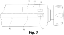
Fig. 3 is a partial bottom view of the injection pen ofFig. 1 illustrating aspects of a system for determining remaining medication; and -
Fig. 4 is a side view of the injection pen ofFig. 1 in a state of disassembly after its held cartridge has been exhausted of deliverable medication. - Corresponding reference characters indicate corresponding parts throughout the several views. Although the drawings represent an embodiment of the present invention, the drawings are not necessarily to scale, and certain features may be exaggerated or omitted in some of the drawings in order to better illustrate and explain the present invention.
- Referring now to
Figs. 1-4 , there is shown a reusable medication delivery device equipped with a sensing system that allows a determination of medication remaining after first recognizing as full a medication cartridge when newly installed in the device. The device is a reusable pen-shaped medication injection device, generally designated 100, which is manually handled by a user to selectively set a dose and then to inject that set dose. Injection devices of this type are well known, and the description ofdevice 100 is merely illustrative as the sensing system can be adapted for use in variously constructed pen-shaped medication injection devices, as well as differently shaped injection devices and other medication delivery devices in general. -
Medication injection device 100 includes a housing that supports the internal components of the device. The housing is shown as having a rear ormain housing 102 and a forward orcartridge housing 104.Main housing 102 holds a mechanical drive mechanism of the device.Cartridge housing 104, also known as the cartridge retainer, holds acartridge 106 filled with medication to be delivered by device operation.Cartridge retainer 104 is detachably mountable tomain housing 102 viaexternal threading 110 on a protrudingcollar portion 112 ofmain housing 102 which mates withinternal threading 114 on aring portion 116 at the proximal end ofcartridge retainer 104. Suitable detachable mounting elements other thanthreadings -
Cartridge retainer 104 includes aninternal hollow 105 suited to removably receivecartridge 106, thereby allowing a cartridge to be inserted therein, and then removed therefrom when depleted and replaced with a fresh cartridge of similar design.Openings 118 incartridge retainer 104 allow visibility of the cartridge contents. Adetent feature 120 provided on the exterior ofcartridge retainer 104 allows for a not shown protective cap to be detachably mounted over thecartridge retainer 104 when aneedle assembly 125 is not attached to thecartridge retainer 104. Althoughcartridge retainer 104 is described herein as being a reusable component, thecartridge retainer 104 could be integrated with, and therefore be disposable with, thecartridge 106. -
Medication cartridge 106 is of conventional design, including abarrel 130 having an interior reservoir filled with medication which is sealed at one end by a slidable plunger orpiston 132 and sealed at the other end by aseptum 134 held by acrimp ring 136. - A
needle assembly 125 detachably mountable to an externally threadedproximal end 122 ofcartridge retainer 104 pierces theseptum 134 when so mounted. The pierced septum through which the needle extends serves as an outlet during dispensing for the medication within the reservoir ofbarrel 130, which medication is delivered through theneedle assembly 125 by operation ofdevice 100. Thecartridge 106 can hold multiple doses of medication, or even a single dose, depending on the purpose ofdevice 100. -
Medication injection device 100 is shown inFig. 1 in its "zero position" at which the device has not been set for delivery of any dose. This zero position setting is indicated by the number "0" visible on thedose display 140 inFig. 1 . InFig. 2 ,device 100 is arranged after being manipulated to set a dose of thirty units for delivery, and the number "30" would be visible on thedisplay 140. -
Medication injection device 100 is typical of many such reusable devices in including a manually-powered dose delivery mechanism, generally designated 150, that controls forward advancement of a drive member, generally designated 160.Drive member 160 advances within thecartridge barrel 130 to directly engage and advanceplunger 132. As shown inFig. 2 ,dose delivery mechanism 150 includes adose knob 152 connected via atube 154 to a mechanical drive assembly abstractly indicated at 156 that is housed withinmain housing 102. Whenknob 152 is turned by a user to set a dose for injection,dose knob 152 andtube 154 screw out together frommain housing 102. When a user applies a plunging force on theproximal end 158 ofdose knob 152, the resulting simply translational motion ofdose knob 152 andtube 154 forward intomain housing 102 is converted bydrive assembly 156 into a smaller motion ofdrive member 160 forward frommain housing 102 into the interior ofcartridge barrel 130. -
Drive member 160 is formed in two pieces including aforward end 163 that directly engages thecartridge plunger 132, and ashaft 165 that axially extends rearward from forwardend 163 intomain housing 102. Theshaft 165 is threaded at 167 and is engaged withdrive assembly 156 to be screwed out frommain housing 102 as it is driven forward.Forward end 163 is provided in the form of an enlarged foot that is mounted onshaft 165 to allow relative rotation, allowingfoot 163 to engageplunger 132 without relative rotation therebetween asshaft 165 screws out. While this foot and shaft two-piece construction ofdrive member 160 is preferred whenshaft 165 screws out from the housing during advancement, such a construction is not required in devices, particularly if the drive member simply translates within the housing, in which case a single piece drive member construction may be more acceptable. -
Device 100 uses anelectronic dose display 140 rather than a helically marked dial display as used in many other reusable injection devices.Display 140 is circuited to and controlled by an electronic controller or computingassembly 170 mounted withinmain housing 102.Controller 170 is programmed and has memory sufficient to achieve the electronic features ofdevice 100. The set dose displayed indisplay 140 is determined by the interaction ofdose delivery mechanism 150 with a sensor mechanism or system, abstractly shown at 175, which is circuited with and controlled bycontroller 170. Such asensor mechanism 175 can be, for example, an electrical, magnetic, optical, audible, ultrasonic or other sensing technology as is known in the art. Providedsensor mechanism 175 is equipped with a feature as is known in the art allowing thecontroller 170 to recognize when a set dose is in fact delivered,such sensor mechanism 175 can serve to determine the amount of medication delivered bydose delivery mechanism 150 when operated to deliver the set dose. Alternatively, other mechanisms to determine the amount of medication delivered by operation ofdose delivery mechanism 150 may be used indevice 100. Such an alternate mechanism includes a system that does not sense the amount of a set dose but merely senses, such as using electrical, magnetic, optical, audible, inductive or other sensing means as is known in the art, a delivered dose, including but not limited to a sensor mechanism that determines positions of, for example, a drive element before and after an injection to allow a dose delivery amount to be calculated by the controller based on the distance the drive element is sensed to have moved. - The foregoing description of
device 100 is intended to be illustrative and not limiting as the sensing system that allows determination of medication remaining in a cartridge as described further below may be used in other differently configured devices.Device 100 is similar in many respects to a device described in International Publication NumberWO 02/092153 - The system for determining remaining medication uses both a sensor for sensing
drive member 160, and a sensor for sensing thecartridge 106 and/orcartridge retainer 104. - The drive
member sensing sensor 190 is mounted withinmain housing 102 and circuited with and controlled bycontroller 170.Sensor 190, which may be composed of a single sensing element or an array of multiple sensing elements, serves to sense the sensible element, generally indicated at 194, ofdrive member 160. -
Sensor 190 is fixed within the length ofmain housing 102 in order to sensesensible element 194 to allow a determination of whetherdrive member 160 is pushed back from a fully advanced or forward position a distance needed to accommodate a new full cartridge. One possible positioning ofsensor 190 withinhousing 102 is at a sensing point, or a point slightly forward of such point, where it is triggered by thesensible element 194 just as theforward end 163 ofdrive member 160 reaches an axial position at which it could be expected to abut or initially engage the proximal face of aplunger 132 in afull cartridge 106 that is within the fully assembleddevice 100. The axial position of thedrive member 160 at such arrangement is known as the cartridge full retracted position, though it will be appreciated that variability due to tolerances of the device and the cartridges means thedrive member 160 might be slightly differently so positioned within the housing from cartridge to cartridge. For example, some cartridges are nominally 300 unit cartridges. Thesensor 190 may be positioned withinmain housing 102 at a position where it is triggered by sensingelement 194 when thedrive member 160 is retracted a distance corresponding to 295-300 units of delivery from the fully advanced forward position, where the 300 units of delivery position may be considered the cartridge full retracted position. - The positioning of
sensor 190 may be forward or rearward of these points, but preferably is not so far rearward within themain housing 102 that is might fail to recognize a drive member that is merely retracted sufficiently far for the smallest full cartridge within tolerances with which the device may be used. For example, in at least some reusable injection devices, the drive member can be manually pushed back into the housing during device resetting a distance that is farther than required to accommodate a full cartridge within tolerances then loaded into the device for use. Having thesensor 190 be triggered only when thedrive member 160 is pushed all the way back to its physical stop in such a device would lead to the device not recognizing some or possibly all cartridges that should be considered full. -
Sensor 190 may be positioned more forward of the sensing point than as described above if the possibility of false positive recognitions are acceptable, particularly if a checking feature as described further below is implemented. For example, and again for a nominally 300 unit cartridge, thesensor 190 may be positioned withinmain housing 102 at a position where it is triggered by sensingelement 194 when thedrive member 160 is retracted a distance corresponding to, for example, any of 250, 260, 270, 280 or 290 units of delivery from the fully advanced forward position, especially if positioning the sensor at, for example, 300 units would require the device to be unacceptably longer. - Alternatively considered, and considering the total possible travel distance a drive member can move relative to the main housing to be equal to the distance between where the drive member is located when fully advanced forward and where the drive member is located when fully manually pushed rearward during reset,
sensor 190 can be positioned up to, for example, one-half, or a third, or a fourth, or a fifth of such total possible travel distance forward of such sensing point. - One suitable type of sensor for
sensor 190 is a magnet sensor that generates a signal that goes form a low amplitude to a high amplitude as thesensible element 194 passes by, or passes through a point at which transverse to the axial direction it is aligned with,sensor 190 when moving in the rearward or retraction direction. Such change in amplitude can be considered a switch triggering. The change from low amplitude to high amplitude is not instantaneous but rather has a transition slope during sensible element travel, with stronger magnets forsensible element 194 producing steeper transition slopes. - As
sensible element 194 ondriver member 160 continues to be further retracted from where the signal transitions, the signal generated bysensor 190 tapers slowly in amplitude but continues to have a relatively high value. Assensible element 194 ondriver member 160 moves forward from where the signal transitions, the signal generated bysensor 190, over the range of distances possible indevice 100, rises slightly in amplitude but continues to have a relatively low value. For these high and low signals, the signal resolution is not sufficiently precise to allow a device controller to determine an exact axial position of thedrive member 160 within the housing suitable to allow dose amounts, or delivery volume remaining, to be calculated. The relatively high amplitude of the output ofsensor 190 whendrive member 160 is retracted beyond a point of transverse alignment withsensor 190 allows the controller to recognize the drive member as being retracted within a range of positions rearward of the aligned position. This allows a sensing of an over retraction ofdrive member 160, such as if a user, whiledevice 100 was disassembled and in preparation of loading areplacement cartridge 106, manually pushes thedrive member 160 rearward into themain housing 102 farther than is needed to prepare for a new full cartridge. The controller can be programmed to consider a signal amplitude found within the signal transition period to be the point at which it considers alignment to have occurred, and the high amplitude and low amplitude outputs otherwise more typically produced by thesensor 190 would be readily recognized as occurring on opposite sides of such alignment point. - With reference to
Fig. 3 ,sensible element 194 is abstractly shown as a discrete feature provided ondrive member shaft 165 near the rearward end of that shaft. A suitablesensible element 194 may be a magnet with its opposite magnetic poles being on opposite axial ends of the sensible element. Alternatively,sensible element 194 could be another form of specialized element coordinated with acomplementary sensor 190. For example,sensible element 194 could be a reflective coating or a character that is readily sensed by anoptical sensor 190. Still further, thesensible element 194 could be the rear end face ofshaft 165 that contacts an electrical switch serving assensor 190, or that otherwise may be sensed as being present or absent, such as by anoptical sensor 190. Other sensing technologies that are known, such as inductive or ultrasonic, alternatively may be used. - Although
sensible element 194 is shown fixed in the rear end ofshaft 165, such a positioning is a not required to practice the present invention but is preferred. In the shown embodiment, in whichcontroller 170 is located within the rearward portion ofhousing 102, such a positioning ofsensible element 194 is useful assensor 190 can be positioned within the rearward portion ofhousing 102 and the length of the electrical connection betweensensor 190 andcontroller 170, be it via spanning wiring or otherwise such as a conductive track on a printed circuit board, is short.Sensible element 194 could be otherwise provided along the length ofshaft 165, such as in the middle or near the forward end of theshaft 165, if a corresponding positional change ofsensor 190 withinhousing 102 were made. - The sensor for sensing the
cartridge 106 is shown at 200 inFig. 2 .Sensor 200 is mounted withinhousing 102 and circuited withcontroller 170.Sensor 200 is constructed to sense the presence or absence of acartridge 106 whenhousing portions sensor 200, with appropriate adaptation ofcartridge 106 if needed, such as an electrical switch or a magnetic or optical sensor. Although shown as directly sensing the cartridge,sensor 200 can indirectly sense the cartridge presence, such as by sensing the position of a device component, such as a drive member-engaging nut, which is moved by contact with a cartridge installed when thehousing portions - Rather than sensing the presence or absence of
cartridge 106,sensor 200 could be positioned to sense the presence of absence ofcartridge retainer 104 operationally assembled tohousing 102. As with sensing of the cartridge described above, such retainer sensing could be done either directly or indirectly. In a retainer sensing scenario, the user would be required to ensure that a cartridge was loaded within thatretainer 104 in order for the remaining dose information that can be provided bydevice 100 as described below to be of any value. In a scenario where the cartridge and retainer were integrated by the manufacturer to be handled as a single cartridge assembly that is disposable as a unit after the cartridge contents are exhausted, thesensor 200 could be adapted to sense the presence of absence of the cartridge assembly mounted tohousing 102, again either directly or indirectly. -
Sensors controller 170 to determine when a new, full cartridge has been loaded intodevice 100, so that remaining medication in that cartridge can be tracked thereafter.Controller 170 continuously monitors the signal fromsensor 200. When the signal fromsensor 200 changes from one associated with no cartridge sensed as present to one associated with acartridge 106 being sensed as present,controller 170 understands or recognizes thatdevice 100 has been assembled with acartridge 106 loaded withincartridge retainer 104. - When a
cartridge 106 is so recognized as present,controller 170 considers the signal fromsensor 190. If the signal thatsensor 190 sends tocontroller 170 is recognized bycontroller 170 asdrive member 160 ofdevice 100 being in a position at which thesensible element 194 is aligned with, or rearward of, thesensor 190, thecontroller 170 associates this combination of signals fromsensors cartridge 106 being a full cartridge. Such a full cartridge status can be shown ondisplay 140, or a display on a device with whichcontroller 170 is linked. -
Controller 170 can then keep track of medication remaining in thecartridge 106 throughout the use ofdevice 100 untilcontroller 170 recognizes, due to a change in signal fromsensor 200, thatcartridge 106 is no longer present. Such tracking is performed bycontroller 170 subtracting, from the original quantity the controller is programmed to expect in a full cartridge, amounts that thedevice 100 is sensed as subsequently dispensing during one or more operations, such as by tracking the information provided bysensor system 175 during injecting operations. The amount calculated bycontroller 170 to be remaining in thecartridge 106 at any given time can be displayed indisplay 140, or a display of a smart device such as a phone if thedevice 100 is linked to it. The user may be notified on such a display of the remaining volume at different times, such as after each dispensing or whenever the pen is turned or when the user manipulates the pen or smart device to query thecontroller 170 as to the medication remaining. - If
sensor 190 is positioned forward of where the sensible element is located when thedrive member 160 is in a cartridge full retraction position, it is possible that a newly installed cartridge that thecontroller 170 believes to be full is not so. Thedevice controller 170 can be programmed to perform checks during later use that identify such fact and then inform the user that remaining medication tracking is not possible for the loaded cartridge. For example, if thesensor 190 were positioned a distance corresponding to 250 units of delivery from the fully advanced forward position of the drive member,controller 170 would expectsensor 190 to identify, via a change in signal from high to low,sensible element 194 being aligned with thesensor 190 after approximately fifty units have delivered during normal use from the cartridge initially determined to be full.Controller 170 can be programmed to recognize that during subsequent device use, when input fromsensor 190 is recognized bycontroller 170 assensible element 194 having reachedsensor 190 sooner than would have been expected had the installed cartridge been full, that a not full cartridge had been installed previously. For the above example, if a cartridge filled with 270 units had been newly installed, which cartridge would have been thought bycontroller 170 to have been full of 300 units, the fact that thesensor 190 will change its output after twenty units have been delivered, as opposed to fifty units as expected by the controller, will cause thecontroller 170 to recognize the prior error in believing the cartridge was full. Thecontroller 170 will understand that the calculated quantity of medication remaining in the installed cartridge after medication delivery is not reliable in such a circumstance, and can send an appropriate message to the user indisplay 140, or other linked display, such as "medication remaining tracking no longer available for this cartridge". - It will be appreciated that
controller 170 can account for different concentrations of medication incartridge 106, such as by working with a sensor of info about the concentration from the cartridge, or by a user inputting such info intodevice 100 either directly by device manipulation or via an electronic downloading of such information, such that the medication amount remaining, as well as dose set and injected, can be tracked as units and not volume. The controller may also track the actual time, or relative time of, cartridge changes, which can then be communicated wirelessly to an external device, such as a smartphone having an application that accepts and uses such data. The controller also may monitor device states that indicate errors or malfunctions that can be alerted on the display or wirelessly sent to a remote device, such as a smartphone. - When the cartridge contents are exhausted by reason of the
drive member 160 having been advanced by medication dispensing operations ofdevice 100, the user can disassembleretainer 104 frommain housing 102 by unscrewing them apart. Such a disassembled state is shown inFig. 4 . When so disassembled, the signal sent bysensor 200 tocontroller 170 is recognized ascartridge 106 being no longer present indevice 100.Display 140 can be controlled to indicate that no cartridge is present in thedevice 100. - A user then can prepare the
device 100 for future operation in the following manner. After removing the spentcartridge 106 fromretainer 104 and inserting areplacement cartridge 106 in theretainer 104, the user can arrange theretainer 104 andmain housing 102 such that the drive memberforward end 163 is insertably aligned with thecartridge barrel 130, and then theretainer 104 andmain housing 102 can be moved together axially and operationally secured, causing thedrive member 160 to be driven rearward by the contact offorward end 163 with the rear face ofcartridge plunger 132 . After such an assembling ofretainer 104 withmain housing 102,controller 170 will again recognize the presence ofcartridge 106, due to the input fromsensor 200. Further, it will be appreciated that if thecartridge 106 inretainer 104 is full, thedrive member 160 will have been shifted rearward to a point thatsensible element 194 reached or passedsensor 190, allowing thecontroller 170 to recognize that a full cartridge is present and that medication remaining can then be tracked as described above. If, however,sensor 190 does not sense thatsensible element 194 has reached or passed it,controller 170 will recognize that a partially full, or previously used,cartridge 106 was installed and provide an appropriate message to the user indisplay 140, or other linked display, such as "partially filled cartridge installed" or "no medication remaining tracking available for this cartridge". - It will be understood that some users, when assembling
device 100 with anew cartridge 106 inretainer 104, may manually pushdrive member 160 back intomain housing 102 with her finger, for example, prior to attachingretainer 104 tomain housing 102. In such a situation, if thedrive member 160 is pushed back beyond the cartridge full retraction position, the preferred ability ofsensor 190 to recognizesensible element 194 and output a high signal allowscontroller 170 to assume a full cartridge has been installed. The controller can still track remaining dose for such a configuration, starting with the programmed number of units in a full cartridge. Since the maximum distance beyond the cartridge full retraction position that drivemember 160 can be pushed back manually in at least some devices is relatively small, any wastage of medication associated withcontroller 170 identifying the cartridge contents as being exhausted after an expected number of units have been expelled, despite the fact that thedrive member 160 may still be able to move forward within thecartridge 106 in such devices, is an acceptable amount. - While this invention has been shown and described as having preferred designs, the present invention may be modified within the spirit and scope of this disclosure. For example, each device could be calibrated when manufactured to determine the output value of
sensor 190, within the transitioning between relatively low and high signals, that best corresponds to the transverse alignment of thesensible element 194 withsensor 190, which output value when stored into the controller to use as a threshold value would provide even greater certainty in a device as to whether a cartridge was full when installed. This application is therefore intended to cover any variations, uses or adaptations of the invention using its general principles. Further, this application is intended to cover such departures from the present disclosure as come within known or customary practice in the art to which this invention pertains. - The following numbered clauses define embodiments of the disclosure and correspond in scope to the claims of the parent application as filed.
- 1. A reusable medication delivery device for delivering medication from a cartridge having a barrel holding the medication between a movable plunger and an outlet, the reusable medication delivery device comprising:
- a main housing;
- a cartridge housing adapted to removably receive the cartridge, said cartridge housing detachably mountable to said main housing;
- a drive member including a forward end for engaging the movable plunger, said drive member having a length extending in an axial direction within the main housing and including a sensible element along a portion of said length;
- a dose delivery mechanism for controlling advancement of said drive member forward within the main housing in the axial direction from a rearward position to a forward position, wherein advancement of said drive member forward in the axial direction, when the cartridge housing receives the cartridge and is mounted to the main housing, moves the movable plunger for delivering medication through the outlet;
- means for determining an amount of medication delivered by operation of said dose delivery mechanism;
- a first sensor for sensing either when said cartridge housing is mounted to said main housing or a presence of the cartridge within said cartridge housing when said cartridge housing is mounted to said main housing;
- at least one second sensor for sensing said sensible element as being located at a position within said main housing which is associated with said drive member being retracted to at least a first retraction position axially rearward of said forward position; and
- a controller in communication with said first sensor and said at least one second sensor and programmed to determine, based on inputs from said first sensor and said at least one second sensor, that a newly installed cartridge is to be considered full or not full of medication, said controller in communication with said determining means and programmed to calculate, based on an input from said determining means after a medication delivery, and if the cartridge was considered full when newly installed, a quantity of medication remaining in the installed cartridge after the medication delivery.
- 2. The reusable medication delivery device of clause 1 wherein said at least one second sensor comprises a magnetic sensor.
- 3. The reusable medication delivery device of
clause 2 wherein said sensible element comprises a magnet disposed at a rearward end of said length of said drive member. - 4. The reusable medication delivery device of clause 1 wherein said first retraction position is associated with an initial engagement of a movable plunger of a full cartridge.
- 5. The reusable medication delivery device of clause 1 wherein said first retraction position is a first amount axially forward of a position associated with an initial engagement of a movable plunger of a full cartridge, said first amount equal to or less than one-half of a total possible travel distance of said drive member relative to said main housing.
- 6. The reusable medication delivery device of clause 5 wherein said first amount is equal to or less than a third of a total possible travel distance of said drive member relative to said main housing.
- 7. The reusable medication delivery device of clause 5 wherein said first amount is equal to or less than a fourth of a total possible travel distance of said drive member relative to said main housing.
- 8. The reusable medication delivery device of clause 5 wherein said first amount is equal to or less than a fifth of a total possible travel distance of said drive member relative to said main housing.
- 9. The reusable medication delivery device of clause 1 wherein said first retraction position is axially forward of a position associated with an initial engagement of a movable plunger of a full cartridge, and wherein if the controller determines the cartridge to be full when newly installed, said controller recognizes during subsequent device use, when input from said at least one second sensor is recognized by said controller as said drive member sensible element having reached said at least one second sensor sooner than would have been expected had the installed cartridge been full, that a not full cartridge had been installed previously and that further calculated quantities of medication remaining in the installed cartridge after medication delivery are not reliable.
- 10. The reusable medication delivery device of clause 1 wherein any input from said at least one second sensor when said drive member is disposed forward of said first retraction position is different from input from said at least one second sensor when said drive member is disposed rearward of said first retraction position, said any input from said at least one second sensor when said drive member is disposed forward of said first retraction position being insufficiently precise so as to preclude said controller from determining an exact axial position of said drive member.
- 11. The reusable medication delivery device of clause 10 wherein said input from said at least one second sensor when said drive member is disposed rearward of said first retraction position is insufficiently precise so as to preclude said controller from determining an exact axial position of said drive member.
- 12. The reusable medication delivery device of clause 10 wherein an amplitude of any input from said at least one second sensor when said drive member is disposed forward of said first retraction position is below a threshold level, and an amplitude of said input from said at least one second sensor when said drive member is disposed rearward of said first retraction position is above the threshold level.
- 13. The reusable medication delivery device of clause 1 wherein said determining means operates without input from said at least one second sensor.
- 14. The reusable medication delivery device of clause 13 wherein said determining means operates without sensing said drive member.
- 15. The reusable medication delivery device of clause 1 further comprising a display upon which is displayed, if the cartridge is considered full when newly installed, the quantity of medication remaining in the installed cartridge after medication delivery.
- 16. The reusable medication delivery device of clause 1 further comprising a display upon which a notification that medication remaining tracking is not available is displayed when said controller, based on inputs from said first sensor and said at least one second sensor, determines that the newly installed cartridge is to be considered not full of medication.
- 17. The reusable medication delivery device of clause 1 wherein said first sensor senses the presence of the cartridge within said cartridge housing when said cartridge housing is mounted to said main housing.
- 18. A reusable medication delivery device for delivering medication from a cartridge assembly having a barrel holding the medication between a movable plunger and an outlet, the cartridge assembly including a first mounting element, the reusable medication delivery device comprising:
- a main housing including a second mounting element cooperatively configured with the first mounting element for a detachable mounting of the cartridge assembly to said main housing;
- a drive member including a forward end for engaging the movable plunger, said drive member having a length extending in an axial direction within the main housing and including a sensible element along a portion of said length;
- a dose delivery mechanism for controlling advancement of said drive member forward within the main housing in the axial direction from a rearward position to a forward position, wherein advancement of said drive member forward in the axial direction, when the cartridge assembly is mounted to the main housing, moves the movable plunger for delivering medication through the outlet;
- means for determining an amount of medication delivered by operation of said dose delivery mechanism;
- a first sensor for sensing when said cartridge assembly is mounted to said main housing;
- at least one second sensor for sensing said sensible element as being located at a position within said main housing which is associated with said drive member being retracted to at least a first retraction position axially rearward of said forward position; and
- a controller in communication with said first sensor and said at least one second sensor and programmed to determine, based on inputs from said first sensor and said at least one second sensor, that a newly installed cartridge assembly is to be considered full or not full of medication, said controller in communication with said determining means and programmed to calculate, based on an input from said determining means after a medication delivery, and if the cartridge assembly was considered full when newly installed, a quantity of medication remaining in the installed cartridge assembly after the medication delivery.
- 19. The reusable medication delivery device of clause 18 wherein said first retraction position is associated with an initial engagement of a movable plunger of a full cartridge assembly.
- 20. The reusable medication delivery device of clause 18 wherein said first retraction position is a first amount axially forward of a position associated with an initial engagement of a movable plunger of a full cartridge assembly, wherein said first amount is equal to or less than a fourth of a total possible travel distance of said drive member relative to said main housing.
- 21. The reusable medication delivery device of clause 18 wherein said first retraction position is axially forward of a position associated with an initial engagement of a movable plunger of a full cartridge assembly, and wherein if the controller determines the cartridge assembly to be full when newly installed, said controller recognizes during subsequent device use, when input from said at least one second sensor is recognized by said controller as said drive member sensible element having reached said at least one second sensor sooner than would have been expected had the installed cartridge assembly been full, that a not full cartridge assembly had been installed previously and that further calculated quantities of medication remaining in the installed cartridge assembly after medication delivery are not reliable.
- 22. The reusable medication delivery device of clause 18 further comprising a display upon which is displayed, if the cartridge assembly is considered full when newly installed, the quantity of medication remaining in the installed cartridge assembly after medication delivery.
- 23. The reusable medication delivery device of clause 18 further comprising a display upon which a notification that medication remaining tracking is not available is displayed when said controller, based on inputs from said first sensor and said at least one second sensor, determines that the newly installed cartridge assembly is to be considered not full of medication.
Claims (17)
- A reusable medication delivery device (100) for delivering medication from a cartridge (106) having a barrel (130) holding the medication between a movable plunger (132) and an outlet, the reusable medication delivery device comprising:a main housing (102);a cartridge housing (104) adapted to receive the cartridge (106), said cartridge housing detachably mountable to said main housing;a drive member (160) including a forward end for engaging the movable plunger (132), said drive member having a length extending in an axial direction within the main housing and including a sensible element (194) along a portion of said length;a dose delivery mechanism (150) for controlling advancement of said drive member forward within the main housing in the axial direction from a rearward position to a forward position, wherein advancement of said drive member forward in the axial direction, when the cartridge housing receives the cartridge and is mounted to the main housing, moves the movable plunger for delivering medication through the outlet;means (175) for determining an amount of medication delivered by operation of said dose delivery mechanism;a first sensor (200) for sensing when said cartridge housing is mounted to said main housing;at least one second sensor (190) for sensing said sensible element as being located at a position within said main housing which is associated with said drive member being retracted to at least a first retraction position axially rearward of said forward position, wherein said first retraction position is no more than a first amount axially forward of a position associated with an initial engagement of the movable plunger of a full said cartridge, said first amount equal to or less than one-half of a total possible travel distance of said drive member relative to said main housing; anda controller (170) in communication with said first sensor and said at least one second sensor and programmed to determine that a newly installed cartridge is to be considered full of medication when an input from said first sensor (200) changes from a signal associated with no cartridge housing mounted to said main housing to a signal associated with a cartridge housing mounted to said main housing and an input from said at least one second sensor (190) is associated with said drive member being in a position at which said sensible element (194) is aligned with or rearward of the second sensor (190), said controller in communication with said determining means (175) and programmed to calculate, based on an input from said determining means after a medication delivery, and if the cartridge was considered full when newly installed, a quantity of medication remaining in the installed cartridge after the medication delivery.
- The reusable medication delivery device of claim 1 wherein said at least one second sensor (190) comprises a magnetic sensor.
- The reusable medication delivery device of claim 2 wherein said sensible element (194) comprises a magnet disposed at a rearward end of said length of said drive member (160).
- The reusable medication delivery device of claim 1 wherein said first amount is equal to or less than a third of said total possible travel distance of said drive member (160) relative to said main housing (102).
- The reusable medication delivery device of claim 1 wherein said first amount is equal to or less than a fifth of said total possible travel distance of said drive member (160) relative to said main housing (102).
- The reusable medication delivery device of claim 1 wherein any input from said at least one second sensor (190) when said drive member (160) is disposed forward of said first retraction position is different from input from said at least one second sensor when said drive member is disposed rearward of said first retraction position, said any input from said at least one second sensor when said drive member is disposed forward of said first retraction position being insufficiently precise so as to preclude said controller (170) from determining an exact axial position of said drive member.
- The reusable medication delivery device of claim 6 wherein said input from said at least one second sensor (190) when said drive member (160) is disposed rearward of said first retraction position is insufficiently precise so as to preclude said controller (170) from determining an exact axial position of said drive member.
- The reusable medication delivery device of claim 6 wherein an amplitude of said input from said at least one second sensor (190) when said drive member (160) is disposed forward of said first retraction position is below a threshold level, and said amplitude of said input from said at least one second sensor when said drive member is disposed rearward of said first retraction position is above the threshold level.
- The reusable medication delivery device of claim 1 wherein said determining means (175) operates without input from said at least one second sensor (190).
- The reusable medication delivery device of claim 9 wherein said determining means (175) operates without sensing said drive member (160).
- The reusable medication delivery device of claim 1 wherein said first retraction position is associated with an initial engagement of the movable plunger (132) of a full said cartridge (106).
- The reusable medication delivery device of claim 1 wherein said first amount is equal to or less than a fourth of said total possible travel distance of said drive member (160) relative to said main housing (102).
- The reusable medication delivery device of claim 1 wherein said first retraction position is axially forward of a position associated with an initial engagement of the movable plunger (132) of a full said cartridge (106), and wherein if the controller (170) determines the cartridge to be full when newly installed, said controller is programmed to recognize during subsequent device use, when input from said at least one second sensor (190) is recognized by said controller as said drive member sensible element (194) having reached said at least one second sensor sooner than would have been expected had the installed cartridge been full, that a not full cartridge had been installed previously and that further calculated quantities of medication remaining in the installed cartridge after medication delivery are not reliable.
- The reusable medication delivery device of claim 1 further comprising a display (140) upon which is displayed, if the cartridge (106) is considered full when newly installed, the quantity of medication remaining in the installed cartridge after medication delivery.
- The reusable medication delivery device of claim 1 further comprising a display (140) upon which a notification that medication remaining tracking is not available is displayed when said controller (170), based on inputs from said first sensor (200) and said at least one second sensor (190), determines that the newly installed cartridge (106) is to be considered not full of medication.
- The reusable medication delivery device of claim 1, wherein the cartridge housing is adapted to removably receive the cartridge.
- The reusable medication delivery device of claim 1, wherein the cartridge housing and the cartridge are integrated into a single cartridge assembly.
Applications Claiming Priority (3)
| Application Number | Priority Date | Filing Date | Title |
|---|---|---|---|
| US201662300199P | 2016-02-26 | 2016-02-26 | |
| PCT/US2017/018632 WO2017147039A1 (en) | 2016-02-26 | 2017-02-21 | Reusable medication delivery device with remaining medication determination capability |
| EP17708639.4A EP3419697B1 (en) | 2016-02-26 | 2017-02-21 | Reusable medication delivery device with remaining medication determination capability |
Related Parent Applications (2)
| Application Number | Title | Priority Date | Filing Date |
|---|---|---|---|
| EP17708639.4A Division-Into EP3419697B1 (en) | 2016-02-26 | 2017-02-21 | Reusable medication delivery device with remaining medication determination capability |
| EP17708639.4A Division EP3419697B1 (en) | 2016-02-26 | 2017-02-21 | Reusable medication delivery device with remaining medication determination capability |
Publications (2)
| Publication Number | Publication Date |
|---|---|
| EP4338772A2 true EP4338772A2 (en) | 2024-03-20 |
| EP4338772A3 EP4338772A3 (en) | 2024-05-15 |
Family
ID=58213357
Family Applications (2)
| Application Number | Title | Priority Date | Filing Date |
|---|---|---|---|
| EP24155471.6A Pending EP4338772A3 (en) | 2016-02-26 | 2017-02-21 | Reusable medication delivery device with remaining medication determination capability |
| EP17708639.4A Active EP3419697B1 (en) | 2016-02-26 | 2017-02-21 | Reusable medication delivery device with remaining medication determination capability |
Family Applications After (1)
| Application Number | Title | Priority Date | Filing Date |
|---|---|---|---|
| EP17708639.4A Active EP3419697B1 (en) | 2016-02-26 | 2017-02-21 | Reusable medication delivery device with remaining medication determination capability |
Country Status (7)
| Country | Link |
|---|---|
| US (1) | US10722658B2 (en) |
| EP (2) | EP4338772A3 (en) |
| JP (2) | JP6751767B2 (en) |
| CN (1) | CN108697856B (en) |
| AU (1) | AU2017222360B2 (en) |
| CA (1) | CA3014657C (en) |
| WO (1) | WO2017147039A1 (en) |
Families Citing this family (3)
| Publication number | Priority date | Publication date | Assignee | Title |
|---|---|---|---|---|
| EP3731901A1 (en) | 2017-11-23 | 2020-11-04 | Sanofi | Medicament injection device with rotary encoder |
| WO2023132104A1 (en) * | 2022-01-07 | 2023-07-13 | テルモ株式会社 | Liquid drug administration device, method for controlling same, and liquid drug administration system |
| CN115531662B (en) * | 2022-10-08 | 2023-05-09 | 深圳市美迪泰克医药有限公司 | Intelligent electronic booster resetting method based on oral anesthesia injection |
Citations (1)
| Publication number | Priority date | Publication date | Assignee | Title |
|---|---|---|---|---|
| WO2002092153A2 (en) | 2001-05-16 | 2002-11-21 | Eli Lilly And Company | Medication injector apparatus with drive assembly that facilitates reset |
Family Cites Families (22)
| Publication number | Priority date | Publication date | Assignee | Title |
|---|---|---|---|---|
| JP3845857B2 (en) * | 2001-03-15 | 2006-11-15 | ニプロ株式会社 | Simple chemical injector |
| GB0201686D0 (en) * | 2002-01-25 | 2002-03-13 | Dca Design Consultants Ltd | Improvements in and relating to a medicament delivery device |
| EP1690559A1 (en) * | 2005-02-14 | 2006-08-16 | Ares Trading S.A. | Medication delivery device |
| EP2060284A1 (en) * | 2007-11-13 | 2009-05-20 | F.Hoffmann-La Roche Ag | Medical injection device having data input means and a pivotable display |
| EP2393533B1 (en) | 2009-02-05 | 2015-03-25 | Sanofi-Aventis Deutschland GmbH | Medicament delivery devices |
| WO2010092156A1 (en) | 2009-02-13 | 2010-08-19 | Novo Nordisk A/S | Medical device and cartridge |
| WO2011003817A1 (en) | 2009-07-07 | 2011-01-13 | Sanofi-Aventis Deutschland Gmbh | Drug delivery device having mechanical display adjustable by mounting a drug cartridge |
| EP2327431A1 (en) | 2009-11-25 | 2011-06-01 | Letcat Aktiebolag | Medical delivery device |
| WO2011089205A2 (en) | 2010-01-22 | 2011-07-28 | Sanofi-Aventis Deutschland Gmbh | Method and system for determining information related to a drug reservoir |
| JP5598903B2 (en) * | 2010-01-29 | 2014-10-01 | 富士電機エフテック株式会社 | Electric syringe for chemicals |
| WO2012004298A1 (en) * | 2010-07-06 | 2012-01-12 | Novo Nordisk A/S | System for indicating lifetime status for medical component |
| EP2597354B1 (en) | 2010-07-20 | 2016-12-28 | Panasonic Intellectual Property Management Co., Ltd. | Lightbulb shaped lamp |
| EP2468340A1 (en) * | 2010-12-21 | 2012-06-27 | Sanofi-Aventis Deutschland GmbH | Auto injector with an interlock switch detecting the position of the needle shroud |
| WO2012140097A2 (en) | 2011-04-11 | 2012-10-18 | Novo Nordisk A/S | Injection device incorporating dose monitoring |
| CN103796696B (en) * | 2011-05-25 | 2016-02-03 | 赛诺菲-安万特德国有限公司 | There is the agent delivery device of dispensing interface and control the method for this device |
| JP6109834B2 (en) * | 2011-10-07 | 2017-04-05 | ノボ・ノルデイスク・エー/エス | System for determining the position of an element based on a three-axis magnetic sensor |
| US8817258B2 (en) | 2012-05-21 | 2014-08-26 | Common Sensing Inc. | Dose measurement system and method |
| JP6266613B2 (en) | 2012-07-11 | 2018-01-24 | サノフィ−アベンティス・ドイチュラント・ゲゼルシャフト・ミット・ベシュレンクテル・ハフツング | Arrangement and method for determining stopper position |
| EP2950850B1 (en) | 2013-01-29 | 2016-10-26 | Sanofi-Aventis Deutschland GmbH | Arrangement for detecting a position of a plunger |
| JP6336490B2 (en) | 2013-02-19 | 2018-06-06 | ノボ・ノルデイスク・エー/エス | Dose capture cartridge module for drug delivery device |
| US10729852B2 (en) | 2014-02-17 | 2020-08-04 | Noble International, Inc. | Wet injection detection and prevention system and method |
| CN115025324A (en) | 2015-07-31 | 2022-09-09 | 赛诺菲-安万特德国有限公司 | Sensor for a drug delivery device |
-
2017
- 2017-02-21 CN CN201780013082.5A patent/CN108697856B/en active Active
- 2017-02-21 AU AU2017222360A patent/AU2017222360B2/en active Active
- 2017-02-21 WO PCT/US2017/018632 patent/WO2017147039A1/en active Application Filing
- 2017-02-21 EP EP24155471.6A patent/EP4338772A3/en active Pending
- 2017-02-21 CA CA3014657A patent/CA3014657C/en active Active
- 2017-02-21 JP JP2018542147A patent/JP6751767B2/en active Active
- 2017-02-21 US US16/075,744 patent/US10722658B2/en active Active
- 2017-02-21 EP EP17708639.4A patent/EP3419697B1/en active Active
-
2020
- 2020-08-17 JP JP2020137495A patent/JP7045424B2/en active Active
Patent Citations (1)
| Publication number | Priority date | Publication date | Assignee | Title |
|---|---|---|---|---|
| WO2002092153A2 (en) | 2001-05-16 | 2002-11-21 | Eli Lilly And Company | Medication injector apparatus with drive assembly that facilitates reset |
Also Published As
| Publication number | Publication date |
|---|---|
| EP3419697B1 (en) | 2024-05-01 |
| CN108697856A (en) | 2018-10-23 |
| CA3014657C (en) | 2021-07-27 |
| EP4338772A3 (en) | 2024-05-15 |
| EP3419697A1 (en) | 2019-01-02 |
| JP7045424B2 (en) | 2022-03-31 |
| US10722658B2 (en) | 2020-07-28 |
| WO2017147039A1 (en) | 2017-08-31 |
| JP6751767B2 (en) | 2020-09-09 |
| CA3014657A1 (en) | 2017-08-31 |
| US20190038843A1 (en) | 2019-02-07 |
| JP2019506228A (en) | 2019-03-07 |
| CN108697856B (en) | 2021-04-06 |
| JP2020192365A (en) | 2020-12-03 |
| AU2017222360B2 (en) | 2019-08-08 |
| AU2017222360A1 (en) | 2018-07-19 |
Similar Documents
| Publication | Publication Date | Title |
|---|---|---|
| US6913591B2 (en) | Personal injector for liquid medicine | |
| EP2401012B1 (en) | Drug delivery system | |
| JP7045424B2 (en) | Reusable drug delivery device with residual drug determination capability | |
| US11819663B2 (en) | Auto-injection drug delivery device | |
| US11771828B2 (en) | Medication delivery device with mechanical locking system | |
| CN112368039A (en) | Rotational dose sensing module for a disposable drug delivery pen and method of assembling the same | |
| JP2005177071A (en) | Electric injector |
Legal Events
| Date | Code | Title | Description |
|---|---|---|---|
| PUAI | Public reference made under article 153(3) epc to a published international application that has entered the european phase |
Free format text: ORIGINAL CODE: 0009012 |
|
| STAA | Information on the status of an ep patent application or granted ep patent |
Free format text: STATUS: THE APPLICATION HAS BEEN PUBLISHED |
|
| AC | Divisional application: reference to earlier application |
Ref document number: 3419697 Country of ref document: EP Kind code of ref document: P |
|
| AK | Designated contracting states |
Kind code of ref document: A2 Designated state(s): AL AT BE BG CH CY CZ DE DK EE ES FI FR GB GR HR HU IE IS IT LI LT LU LV MC MK MT NL NO PL PT RO RS SE SI SK SM TR |
|
| REG | Reference to a national code |
Ref country code: DE Ref legal event code: R079 Free format text: PREVIOUS MAIN CLASS: A61M0005315000 Ipc: A61M0005240000 |
|
| PUAL | Search report despatched |
Free format text: ORIGINAL CODE: 0009013 |
|
| P01 | Opt-out of the competence of the unified patent court (upc) registered |
Effective date: 20240327 |
|
| AK | Designated contracting states |
Kind code of ref document: A3 Designated state(s): AL AT BE BG CH CY CZ DE DK EE ES FI FR GB GR HR HU IE IS IT LI LT LU LV MC MK MT NL NO PL PT RO RS SE SI SK SM TR |
|
| RIC1 | Information provided on ipc code assigned before grant |
Ipc: A61M 5/315 20060101ALI20240410BHEP Ipc: A61M 5/24 20060101AFI20240410BHEP |