EP4327639A1 - Method for operating an agricultural working system - Google Patents
Method for operating an agricultural working system Download PDFInfo
- Publication number
- EP4327639A1 EP4327639A1 EP23179406.6A EP23179406A EP4327639A1 EP 4327639 A1 EP4327639 A1 EP 4327639A1 EP 23179406 A EP23179406 A EP 23179406A EP 4327639 A1 EP4327639 A1 EP 4327639A1
- Authority
- EP
- European Patent Office
- Prior art keywords
- attachment
- work machine
- axle
- determined
- work
- Prior art date
- Legal status (The legal status is an assumption and is not a legal conclusion. Google has not performed a legal analysis and makes no representation as to the accuracy of the status listed.)
- Pending
Links
- 238000000034 method Methods 0.000 title claims abstract description 65
- 230000008878 coupling Effects 0.000 claims description 22
- 238000010168 coupling process Methods 0.000 claims description 22
- 238000005859 coupling reaction Methods 0.000 claims description 22
- 238000009826 distribution Methods 0.000 claims description 19
- 239000002689 soil Substances 0.000 claims description 17
- 239000000463 material Substances 0.000 claims description 11
- 238000005096 rolling process Methods 0.000 claims description 6
- 230000005484 gravity Effects 0.000 description 12
- 238000005259 measurement Methods 0.000 description 7
- 238000003860 storage Methods 0.000 description 6
- 239000000446 fuel Substances 0.000 description 4
- 239000007788 liquid Substances 0.000 description 4
- 230000005540 biological transmission Effects 0.000 description 3
- 125000004122 cyclic group Chemical group 0.000 description 3
- 239000002828 fuel tank Substances 0.000 description 3
- 239000000725 suspension Substances 0.000 description 3
- 238000013461 design Methods 0.000 description 2
- 238000011161 development Methods 0.000 description 2
- 230000018109 developmental process Effects 0.000 description 2
- 238000011156 evaluation Methods 0.000 description 2
- 210000003608 fece Anatomy 0.000 description 2
- 239000003337 fertilizer Substances 0.000 description 2
- 230000002452 interceptive effect Effects 0.000 description 2
- 239000010871 livestock manure Substances 0.000 description 2
- 239000002002 slurry Substances 0.000 description 2
- 238000005303 weighing Methods 0.000 description 2
- 239000000654 additive Substances 0.000 description 1
- 230000000996 additive effect Effects 0.000 description 1
- 238000009530 blood pressure measurement Methods 0.000 description 1
- 238000002485 combustion reaction Methods 0.000 description 1
- 238000005056 compaction Methods 0.000 description 1
- 230000001419 dependent effect Effects 0.000 description 1
- 230000000694 effects Effects 0.000 description 1
- 238000012544 monitoring process Methods 0.000 description 1
- 238000012545 processing Methods 0.000 description 1
- 230000001953 sensory effect Effects 0.000 description 1
- 238000012546 transfer Methods 0.000 description 1
Images


Classifications
-
- A—HUMAN NECESSITIES
- A01—AGRICULTURE; FORESTRY; ANIMAL HUSBANDRY; HUNTING; TRAPPING; FISHING
- A01B—SOIL WORKING IN AGRICULTURE OR FORESTRY; PARTS, DETAILS, OR ACCESSORIES OF AGRICULTURAL MACHINES OR IMPLEMENTS, IN GENERAL
- A01B71/00—Construction or arrangement of setting or adjusting mechanisms, of implement or tool drive or of power take-off; Means for protecting parts against dust, or the like; Adapting machine elements to or for agricultural purposes
-
- A—HUMAN NECESSITIES
- A01—AGRICULTURE; FORESTRY; ANIMAL HUSBANDRY; HUNTING; TRAPPING; FISHING
- A01B—SOIL WORKING IN AGRICULTURE OR FORESTRY; PARTS, DETAILS, OR ACCESSORIES OF AGRICULTURAL MACHINES OR IMPLEMENTS, IN GENERAL
- A01B63/00—Lifting or adjusting devices or arrangements for agricultural machines or implements
- A01B63/02—Lifting or adjusting devices or arrangements for agricultural machines or implements for implements mounted on tractors
- A01B63/10—Lifting or adjusting devices or arrangements for agricultural machines or implements for implements mounted on tractors operated by hydraulic or pneumatic means
- A01B63/111—Lifting or adjusting devices or arrangements for agricultural machines or implements for implements mounted on tractors operated by hydraulic or pneumatic means regulating working depth of implements
- A01B63/114—Lifting or adjusting devices or arrangements for agricultural machines or implements for implements mounted on tractors operated by hydraulic or pneumatic means regulating working depth of implements to achieve a constant working depth
- A01B63/1145—Lifting or adjusting devices or arrangements for agricultural machines or implements for implements mounted on tractors operated by hydraulic or pneumatic means regulating working depth of implements to achieve a constant working depth for controlling weight transfer between implements and tractor wheels
-
- A—HUMAN NECESSITIES
- A01—AGRICULTURE; FORESTRY; ANIMAL HUSBANDRY; HUNTING; TRAPPING; FISHING
- A01B—SOIL WORKING IN AGRICULTURE OR FORESTRY; PARTS, DETAILS, OR ACCESSORIES OF AGRICULTURAL MACHINES OR IMPLEMENTS, IN GENERAL
- A01B63/00—Lifting or adjusting devices or arrangements for agricultural machines or implements
- A01B63/02—Lifting or adjusting devices or arrangements for agricultural machines or implements for implements mounted on tractors
- A01B63/10—Lifting or adjusting devices or arrangements for agricultural machines or implements for implements mounted on tractors operated by hydraulic or pneumatic means
- A01B63/11—Lifting or adjusting devices or arrangements for agricultural machines or implements for implements mounted on tractors operated by hydraulic or pneumatic means for controlling weight transfer between implements and tractor wheels
-
- A—HUMAN NECESSITIES
- A01—AGRICULTURE; FORESTRY; ANIMAL HUSBANDRY; HUNTING; TRAPPING; FISHING
- A01B—SOIL WORKING IN AGRICULTURE OR FORESTRY; PARTS, DETAILS, OR ACCESSORIES OF AGRICULTURAL MACHINES OR IMPLEMENTS, IN GENERAL
- A01B63/00—Lifting or adjusting devices or arrangements for agricultural machines or implements
- A01B63/02—Lifting or adjusting devices or arrangements for agricultural machines or implements for implements mounted on tractors
- A01B63/10—Lifting or adjusting devices or arrangements for agricultural machines or implements for implements mounted on tractors operated by hydraulic or pneumatic means
- A01B63/111—Lifting or adjusting devices or arrangements for agricultural machines or implements for implements mounted on tractors operated by hydraulic or pneumatic means regulating working depth of implements
- A01B63/112—Lifting or adjusting devices or arrangements for agricultural machines or implements for implements mounted on tractors operated by hydraulic or pneumatic means regulating working depth of implements to control draught load, i.e. tractive force
-
- A—HUMAN NECESSITIES
- A01—AGRICULTURE; FORESTRY; ANIMAL HUSBANDRY; HUNTING; TRAPPING; FISHING
- A01B—SOIL WORKING IN AGRICULTURE OR FORESTRY; PARTS, DETAILS, OR ACCESSORIES OF AGRICULTURAL MACHINES OR IMPLEMENTS, IN GENERAL
- A01B79/00—Methods for working soil
- A01B79/005—Precision agriculture
-
- A—HUMAN NECESSITIES
- A01—AGRICULTURE; FORESTRY; ANIMAL HUSBANDRY; HUNTING; TRAPPING; FISHING
- A01B—SOIL WORKING IN AGRICULTURE OR FORESTRY; PARTS, DETAILS, OR ACCESSORIES OF AGRICULTURAL MACHINES OR IMPLEMENTS, IN GENERAL
- A01B63/00—Lifting or adjusting devices or arrangements for agricultural machines or implements
- A01B63/002—Devices for adjusting or regulating the position of tools or wheels
- A01B63/008—Vertical adjustment of tools
-
- A—HUMAN NECESSITIES
- A01—AGRICULTURE; FORESTRY; ANIMAL HUSBANDRY; HUNTING; TRAPPING; FISHING
- A01B—SOIL WORKING IN AGRICULTURE OR FORESTRY; PARTS, DETAILS, OR ACCESSORIES OF AGRICULTURAL MACHINES OR IMPLEMENTS, IN GENERAL
- A01B63/00—Lifting or adjusting devices or arrangements for agricultural machines or implements
- A01B63/14—Lifting or adjusting devices or arrangements for agricultural machines or implements for implements drawn by animals or tractors
- A01B63/145—Lifting or adjusting devices or arrangements for agricultural machines or implements for implements drawn by animals or tractors for controlling weight transfer between implements and tractor wheels
Definitions
- the present invention relates to a method for operating an agricultural work system according to the preamble of claim 1 and an agricultural work system according to the preamble of claim 15.
- axle loads occurring on the axes of the work machine during the work process which are influenced by the forces of the attachment, which are transferred to the work machine via the device interface.
- the axle loads and the axle load distribution have a significant influence on the overall efficiency when carrying out an agricultural work process as well as the wear and operational safety of the working machine.
- the axle loads of the working system are determined in order to set the axle load distribution required for the operation of the working system using suitable ballasting.
- the ballasting carried out is based on the axle load distribution determined before the agricultural work process begins.
- a device and a method for determining the axle load on the axles of a work machine is from the DE 10 2015 114 262 A1 known.
- axle load distribution is subject to various influences that depend on the configuration of the work system and operating parameters, with the operating parameters in particular being subject to continuous changes during the implementation of the agricultural work process, which directly affect the axle load distribution or the axle load ratio.
- An unadapted setting of the axle load ratio leads to one Increased fuel consumption results in lower area performance, higher area-specific costs and increased wear on the working machine and the attachment.
- the invention is based on the object of designing and developing a method for operating an agricultural work system and an agricultural work system, so that a more efficient operation of the work system is made possible, taking into account dynamically changing conditions during the implementation of an agricultural work process .
- a method for operating an agricultural work system comprising an agricultural work machine having at least two axles with at least one device interface and an attachment, the attachment being connected to the work machine by means of the device interface in order to carry out an agricultural work process, wherein an axle load on at least one axle is determined by means of a sensor arrangement.
- axle loads occurring on the axes of the work machine, in particular vertical ones, and an axle load ratio based thereon, taking into account a work machine and attachment configuration as well as operating parameters are determined cyclically, coupled in time to the execution of the work process, by means of a computing unit of a driver assistance system of the work machine.
- the invention is based on the idea that the axle load distribution is subject to significant changes during ongoing operation of the agricultural work system, ie during the implementation of an agricultural work process, due to changing operating parameters. To what extent and in what way the axle load distribution changes is not known to the operator of the work system and is usually not immediately noticeable.
- the cyclical, in certain, preferably Constant, time intervals, determination of the axle loads occurring on the axles of the work machine and the axle load ratio based on this, taking into account the work machine and attachment configuration as well as the current operating parameters, enables the operator to receive information about the dynamically changing axle loads and the axle load distribution during the operation in almost real time To provide implementation of the work process. This makes it possible to optimize parameters influenced by the axle load ratio, such as fuel consumption, area performance, area-specific costs, soil compaction and the wear and tear on the working machine and the associated attachment, through suitable measures.
- axle load on at least one axle of the work machine in particular the front axle
- An alternative involves a force-distance measuring sensor system on the axis to be measured.
- the driver assistance system can preferably include an operating and display unit, by means of which the occurring axle loads and the axle load ratio as well as their changes are visualized during the implementation of the work process. Using graphically displayed curves for the axle loads, particularly vertical ones, and the axle load ratio, the operator can be alerted at an early stage to changes that have a negative impact on the parameters.
- the existing work machine and attachment configuration can be at least partially specified by an operator of the work system and/or at least partially determined automatically by the driver assistance system.
- the determination of the dynamically changing axle loads can therefore be based on an initial ballasting of the work system, which represents the initial values necessary for the subsequent determination during the work process.
- the work machine configuration and the attachment configuration can be at least partially selected by the operator of the work system from a database stored in a storage unit of the driver assistance system.
- the driver assistance system can be in an interactive dialogue with the Operator determine at least part of the work machine configuration and/or the attachment configuration.
- the driver assistance system can be set up to determine the attachment.
- the driver assistance system can be set up, for example, to communicate with an attachment control or to read out a data memory on the attachment.
- the subject of the work machine configuration includes, among other things, the mass of the work machine, the center of gravity of the empty work machine, the mass and position of additional weights arranged on the work machine, and the type of device interface on the work machine for connection to the attachment.
- the mass of the work machine When it comes to the weight forces resulting from the mass of the work machine and the weights attached to it, the influence of the terrain topology, inclines and slopes, must be taken into account.
- the subject of the attachment configuration includes, among other things, the mass of the attachment, the center of gravity of the attachment, the point of application of the ground resistance forces/rolling resistance within the attachment, and the position of at least one weight-supporting device optionally arranged on the attachment.
- the mass of the attachment can also be influenced by storage containers arranged on it with varying fill levels, which can also be the subject of the attachment configuration.
- an estimate of the ground resistance forces on tools for cultivating the soil of an attachment can be made using tractive power and vehicle speed.
- the traction power in turn, can be determined by means of drive engine power, transmission efficiency, drive train efficiency and the efficiency of the ground intervention means.
- the tractive power can be estimated using transmission output power, drive train efficiency and an efficiency of the ground intervention means.
- Other operating parameter combinations for estimating train performance are conceivable.
- the device interface is generally a mechanical coupling between the working machine and the attachment.
- the device interface can be designed as a three-point power lift.
- the device interface can be designed as a front or rear power lift.
- the device interface can be a drawbar.
- Other variants for the device interface are systems with a simple pull pin coupling, with a hitch hook, with a ball head coupling or the like.
- a device interface load transmitted to the work machine via the at least one device interface can be determined specifically for the attachment.
- the device interface load includes weight-related load components, which are gravity-related and/or inertia-related load components, as well as process-related load components, which are due, for example, to the engagement between the attachment and the field soil that takes place during plowing or the like.
- a vertical force supported on at least one weight-supporting device can be determined in a first step from a moment equilibrium about one of the axes, in particular the rear axle, of the working machine, and in a second step, a vertical axle load acting on this axis can be determined become. If an axle load is determined using the sensor arrangement on the rear axle, the vertical force supported on the at least one weight-supporting device can be determined from a moment equilibrium around the front axle.
- tool forces exerted on tools of the attachment can be determined via tractive power and current travel speed of the working machine, a coupling moment acting from the attachment on the working machine and a vertical coupling force by means of attachment geometry and the determination of a moment balance around the at least one weight-supporting Device can be determined and in a second step a vertical axle load acting on one of the axles, in particular the rear axle, can be determined.
- an estimation of the rolling resistance can be carried out in a first step to determine the coupling forces and in a second step one can be applied to one of the axles, in particular the rear axle. acting vertical Axle load can be determined.
- An attachment used to transport crops, auxiliary materials and/or operating materials can be a liquid manure tank, a transport trailer and the like.
- a variable filling volume of a container of the attachment and/or the work machine and/or the spatial arrangement of the container in relation to the work machine can be taken into account when determining the axle load.
- containers with a variable filling volume include an additive tank, a seed and/or fertilizer container, a liquid container for a crop protection sprayer, a liquid manure tank and the like.
- the location or spatial arrangement as well as information on the maximum filling volume of a container can result from the attachment configuration and/or the working machine configuration.
- An actual fill level which can change continuously while an agricultural work process is being carried out, can be detected by sensors and evaluated by the computing unit of the driver assistance system or a separate evaluation unit.
- the axle load ratio can be determined and in a fourth step, an estimate of a drive torque on the axles of the work machine can be carried out.
- the execution of the third and fourth steps is independent of whether the attachment is attached or attached.
- an estimate of a driving force coefficient can be carried out using variables determined in the first and second steps for attached or attached attachments.
- the respective design of the ground engagement means of the machine can have an influence. If crawler tracks are provided on at least one axle instead of wheels as ground engagement means, separate consideration of the mechanical properties and/or the design of the crawler tracks is provided.
- the estimation of the driving force coefficient can be carried out by means of an estimation of a tractive force, which can be determined from the tractive power and the current driving speed of the work machine.
- a dialog-based process can be specified by the driver assistance system to determine an initial ballasting of the work machine.
- the dialog-based, especially interactive, process simplifies the determination of the initial ballasting.
- influences on the procedural determination of the current axle load can be taken into account.
- no specific background knowledge is required on the part of the operator to determine the initial ballasting if he is guided through the necessary sub-steps for determining the initial ballast using a predetermined step-by-step sequence of actions.
- At least a determination of the empty weight and center of gravity of the work machine, a calibration of an axle load measurement on the at least one axle to be measured, in particular the front axle, a determination of a coupling torque, in particular with a torque-transmitting traction booster, for attached attachments and a determination a focus on attached attachments can be carried out.
- the driver assistance system can compare the vertical axle loads and the axle load distribution determined cyclically during the execution of the work process with limit values and, if one of the limit values is passed, a warning can be issued using the operating and display unit.
- the warning can be used, for example, to indicate whether the technical or legal axle loads are exceeded or undershot.
- the driver assistance system can determine an adjustment of at least one operating parameter when one of the limit values is passed, which is suggested to the operator by means of the operating and display unit for manual selection and/or manual implementation and/or is automatically implemented by the driver assistance system can.
- Adaptable operating parameters of the agricultural work system are, for example, changing the ballast attached to the front or rear or an, in particular automated, adjustment of the tire pressure using a tire monitoring system, using a compressor or the like.
- Further adjustable operating parameters can be a control of pneumatic or hydropneumatic spring units of the work machine, chassis rigidity of the work machine and/or a tractive force.
- an adjustment of one or more setting parameters of the attachment can be suggested.
- the cyclic determination of the vertical axle loads and the axle load ratio can also be used to calibrate transmission and braking parameters.
- an agricultural work system comprising an agricultural work machine having at least two axes with at least one device interface and an attachment which is connected to the work machine by means of the device interface for carrying out an agricultural work process, with a sensor arrangement on at least one axis for determination an axle load is arranged, wherein the work machine comprises a driver assistance system with a computing unit, which is set up to time-coupled axle loads occurring on the axles of the work machine and an axle load ratio based thereon, taking into account a work machine and attachment configuration as well as operating parameters, to the execution of the work process determine.
- the agricultural work system is set up in particular to carry out the method according to one of claims 1 to 14. Reference may be made to all explanations of the method according to the invention.
- FIG. 1 A work machine 1 of an agricultural work system is shown schematically in a side view.
- the working machine 1 designed as a tractor, includes ground engagement means 4, 5 arranged on axles 2, 3, which are designed here as running wheels.
- Axle 2 is hereinafter referred to as the front axle and axle 3 as the rear axle.
- the work machine 1 is equipped with a - only schematically indicated - drive unit 6, which here and preferably has an internal combustion engine.
- the drive unit 6 acts in the usual way via a drive train on the ground engagement means 4, 5.
- the work machine 1 is preferably an all-wheel drive work machine 1, so that all four ground engagement means 4, 5 are driven or can be driven.
- the work machine 1 has a driver assistance system 7, to which an operating and display unit 8 is assigned, which provides an information interface to the operator of the work machine 1.
- the driver assistance system 7 has a storage unit 10 for storing data and a computing unit 9 for processing the data stored in the storage unit 10.
- a container 11 designed as a fuel tank is integrated into the body of the work machine 1.
- the container 11 is designed with a fill level sensor 12, which transmits measurement data to the driver assistance system 7 for evaluation via a signal line.
- a sensor arrangement 13 is assigned to at least one of the axes 2, 3 of the work machine 1. Here and preferably the sensor arrangement 13 is assigned to the front axle 2.
- the axle load occurring on the front axle 2 can be determined using the measurement data provided by the sensor arrangement 13 and evaluated by the driver assistance system 7.
- FIG. 1 schematically and by way of example a device interface 14 of the work machine 1.
- the work machine 1 which is designed in particular as a tractor, usually has such a device interface 14 on the front and rear.
- the device interface 14 is generally a mechanical coupling between the work machine 1 and an attachment 15.
- the device interface 14 can be designed in particular as a three-point power lift.
- FIG. 2 The agricultural work system consisting of the work machine 1 and the attachment 15 attached to the device interface 14 is shown schematically.
- the attachment 15 attached to the device interface 14 can be a soil cultivation device such as a plow, a cultivator, a harrow or the like.
- Absolute axle loads and axle load distribution have a high influence on overall efficiency and operational safety when carrying out agricultural work processes.
- an ideal axle load ratio depends on the tires.
- the load transfer from the attachment 15 to the work machine 1 to reduce the tractive force requirement and rolling resistance influences the axle load distribution and the absolute axle loads.
- the axle load distribution during the implementation of a soil cultivation process is influenced by the soil resistance and/or the fill level of a container of the attachment 15. Another aspect is that the front axle load must not fall below a minimum in order to ensure adequate steering behavior.
- the axle load ratio or the absolute axle loads should remain within designed limits to ensure the service life of the drive train.
- a setting of the axle load distribution that deviates significantly from an optimal setting results in increased fuel consumption, reduced area performance, higher area-specific costs and increased wear and tear on the agricultural work system.
- operating parameters of the work system can change continuously, which is due to external influences, such as soil conditions, or internal influences, such as changes the weight of the attachment 15 due to fill level fluctuations. It is therefore essential for an operator of the work system to at least be informed about the currently prevailing, in particular vertical, axle loads and the resulting axle load ratio while carrying out agricultural work processes.
- axle loads occurring on the axes 2, 3 of the work machine 1 and an axle load ratio based thereon are determined cyclically, coupled in time to the execution of the work process, by means of the computing unit 9 of the driver assistance system 7 of the work machine 1.
- the cyclic determination, carried out at specific, preferably constant, time intervals, of the axle loads occurring on the axes 2, 3 of the work machine 1 during the execution of the work process and the axle load ratio based thereon makes it possible to provide the operator with information about the dynamically changing axle loads in approximately real time and to provide axle load distribution during the execution of the work process.
- the occurring axle loads and the axle load ratio as well as their changes can be visualized while carrying out the work process.
- the operator can be alerted at an early stage to changes that have a negative impact on the operation of the work system using graphically displayed curves for the axle loads, particularly vertical ones, and the axle load ratio.
- An existing work machine and attachment configuration can be at least partially specified by the operator of the work system and/or at least partially determined automatically by the driver assistance system 7.
- the subject of the work machine configuration includes, among other things, the mass of the work machine 1, the center of gravity of the empty work machine 1, the mass and position of additional weights arranged on the work machine 1, such as front weight, wheel weight, front loader, container or the like, and the type of device interface 14 on the work machine 1 for connection to the attachment 15.
- the subject of the attachment configuration is, among other things, the mass of the attachment 15, the center of gravity of the attachment 15, the force application point of the ground resistance forces and / or rolling resistance within the attachment 15, the position of at least one weight-supporting device optionally arranged on the attachment 15, such as a support wheel arrangement 17.
- a device interface load L transmitted via the at least one device interface 14 is determined specifically for the attachment.
- attachment-specific means that a distinction is made between the type of attachment 15, for example a soil cultivation device or slurry tanker, and the connection to the device interface 14 by attaching or attaching it and/or using a traction booster.
- the device interface load L includes weight-related load components, which are gravity-related and/or inertia-related load components, as well as process-related load components, which are due, for example, to the engagement between the attachment 15 and field soil, which takes place during plowing or the like.
- the work system shown shows the attached attachment 15, which in the exemplary embodiment is designed as a soil cultivation device Fig. 2
- the forces shown acting on the work machine and the attachment 15 are shown in relation to a coordinate system K of the work system.
- the device interface load L includes weight forces F G,impl,x and F G,impl,z acting in the x-direction and in the z-direction, which act at the center of gravity S imp of the attachment 15.
- the device interface load L includes forces F Tool,x , F Tool,z , F Roller,x , F Roller,z acting in the x-direction or in the z-direction, which are from tools 16 or the at least one as a support wheel arrangement 17 executed weight-supporting device.
- the x-direction denotes the vehicle's longitudinal direction
- the y-direction denotes the vehicle's transverse direction
- the z-direction denotes the vehicle's vertical direction.
- a weight 18 for ballasting is arranged on the front device interface 14.
- weight forces F FW,x and F FW,Z acting in the x direction and in the z direction act.
- Horizontal and vertical axle loads F FA,x and F FA,z acting in the x-direction and z-direction as well as a moment M FA,y acting in the y-direction act on the front axle 2.
- weight forces F G,tractor,x and F G,tractor,z act in the x-direction and in the z-direction.
- the weight forces F G,tractor,x and F G,tractor,z of the work machine 1 must be determined taking into account the terrain topology, an inclination in the vehicle's transverse and longitudinal directions.
- the weight 18 on the front device interface 14 is to be understood as an example. Additional weights 18 with corresponding weight forces, taking into account the terrain topology and own centers of gravity, must be taken into account if, for example, additional wheel weights are provided or the attachment 15 includes an additional container for seeds and/or fertilizer or a liquid. Fill levels of a container of the attachment 15 can also be determined by a sensor arrangement. It is also conceivable to determine the weight force exerted by the container contents in order to record changes in the weight of the attachment 15 in order to take these into account in the cyclical determination of the vertical axle loads F FA,z and F RA,z .
- the vertical force F Roller,z supported on the support wheel arrangement is determined from a moment equilibrium about the rear axle 3 of the work machine 1.
- the vertical axle load F RA,z acting on the rear axle 3 is determined.
- the axle load ratio is determined from the vertical axle loads F FA,z , F RA,z currently acting on the axes 2, 3 and in a fourth step, an estimate of the drive torques M FA,y and M RA,y is made on the Axes 2, 3 of the work machine 1 carried out.
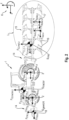
- FIG. 3 is a schematic representation of only the work machine 1 in an operating situation in which an attachment 15 is attached to the device interface 14.
- An ordering combination may be mentioned as an example of an attached attachment 15.
- the device interface load L includes coupling forces F Koppel,x and F Koppel,z acting in the x-direction and z-direction as well as a coupling moment M Koppel,y acting in the y-direction, which act in the coupling point 18 on the device interface 14.
- a trailed attachment 15 which is designed for soil cultivation
- tool forces exerted on tools 16 of the attachment 15 are determined via the tractive power and current driving speed of the work machine 1, a coupling torque M Kop-pel acting from the attachment 15 on the work machine 1, y and a vertical coupling force F coupling,z determined by means of attachment geometry, which is determined from the attachment configuration, and a moment balance formed around a support wheel arrangement 17.
- the vertical axle load F RA,z acting on one of the axles 2, 3, in particular the rear axle 3, is determined.
- an estimation of the rolling resistance is carried out in a first step to determine the coupling forces F Koppel,x and F Koppel,z .
- the vertical axle load F RA,z acting on one of the axles 2, 3, in particular the rear axle 3, is determined.
- the axle load ratio is determined from the vertical axle loads F FA,z , F RA,z currently acting on the axles 2, 3 determined and in the fourth step an estimate of the drive torques M FA,y and M RA,y on the axes 2, 3 of the work machine 1 is carried out.
- an estimate of a driving force coefficient can be made using variables determined in the first and second steps, the weight forces F Fw,x , F G,tractor,x , F G,imp,x , the force in x caused by the support wheel arrangement -Direction F Roller,x , as well as the vertical axle loads F FA,z , F RA,z on the front axle 2 and rear axle 3, for trailed or attached attachments 15.
- the attachment 15 can also be designed with containers, as already explained above.
- the variable filling volume of a container of the attachment 15 and/or the work machine 1 and/or the spatial arrangement of the container 11 in relation to the work machine 1 is taken into account when determining the dynamically changing vertical axle loads F FA,z , F RA,z .
- the position or spatial arrangement of a container on the work machine 1 and the attachment 15 can be determined, among other things, by an operator input using the operating and display unit 8 from the work machine and attachment configuration stored in the storage unit 10.
- the change in fill level can be detected using sensors.
- the initial ballasting includes data on the empty weight of the working machine 1, the initial axle load distribution, and a coupling torque, provided that a trailed attachment 15 with a torque-transmitting traction force amplifier is used.
- knowledge of the center of gravity S imp of the attachment 15 is relevant.
- a dialog-based process can be specified by the driver assistance system 7.
- the operator can be instructed via the operating and display unit 8 via a natural language dialogue in order to carry out the necessary steps and inputs.
- a sequence of steps can be provided that includes weighing on a scale.
- the proportional weight of the work machine 1 can first be recorded, which only has the front axle 2 on the scales.
- a measurement routine can then be carried out, by means of which an initial vertical axle load is determined by the sensor arrangement 13.
- the work machine 1 is then completely moved onto the scales and weighed.
- the fuel level in container 11 is determined.
- an attachment calibration which is carried out after the attachment 15 has been attached or attached.
- the proportional weight of the work machine 1 with the attachment 15 arranged on it will be recorded here, which only stands on the scales with the front axle 2.
- the measurement routine can then be carried out, by means of which the initial vertical axle load is determined by the sensor arrangement 13, taking the attachment 15 into account. If a traction booster is provided in the case of the attached attachment 15, this is switched on and the proportional weighing and the subsequent measuring routine are carried out again. The traction booster is then switched off.
- the work machine 1 with attached or attached attachment 15 is then moved onto the scales, with only the axes 2, 3 of the work machine 1 being on the scales.
- the at least one optional support wheel arrangement 17 of the attachment 15 or wheels of an attachment 15 designed as a transport trolley or slurry tank are not on the scales. After the weight of the working device 1 has been recorded, the entire working system is moved onto the scales in order to determine the total weight. Subsequently, to determine the weight acting on at least one attachment axle, the attachment 15 with its at least one support wheel arrangement 17 or the vehicle axles is moved onto the scales in order to record the weight of the attachment axle.
- the driver assistance system 7 can be used to compare the vertical axle loads F FA,z , F RA,z and the axle load distribution that are cyclically determined during the execution of the work process with limit values. If one of the limit values is passed, at least one warning message can be issued using the operating and display unit 8. The operator can thereby be made aware at an early stage of an operating situation in which optimal operation of the work system is not possible with the existing operating parameters.
- the driver assistance system 7 can determine an adjustment of at least one operating parameter when one of the limit values is passed, which is suggested to the operator for manual selection and/or implementation by means of the operating and display unit 8 and/or is automatically implemented by the driver assistance system 7.
Landscapes
- Life Sciences & Earth Sciences (AREA)
- Engineering & Computer Science (AREA)
- Mechanical Engineering (AREA)
- Soil Sciences (AREA)
- Environmental Sciences (AREA)
- Agricultural Machines (AREA)
- Management, Administration, Business Operations System, And Electronic Commerce (AREA)
Abstract
Die vorliegende Erfindung betrifft ein Verfahren zum Betreiben eines landwirtschaftlichen Arbeitssystems, umfassend eine zumindest zwei Achsen (2, 3) aufweisende landwirtschaftliche Arbeitsmaschine (1) mit zumindest einer Geräteschnittstelle (14) sowie ein Anbaugerät (15), welches mittels der Geräteschnittstelle (14) mit der Arbeitsmaschine (1) zur Durchführung eines landwirtschaftlichen Arbeitsprozesses verbunden wird, wobei eine Achslast (F<sub>FA,x</sub>, F<sub>FA,z</sub>, F<sub>RA,x</sub>, F<sub>RA,z</sub>) an zumindest einer Achse (2, 3) mittels einer Sensoranordnung (13) bestimmt wird, wobei an den Achsen (2, 3) der Arbeitsmaschine (1) auftretende Achslasten (F<sub>FA,x</sub>, F<sub>FA,z</sub>, F<sub>RA,x</sub>, F<sub>RA,z</sub>) und ein darauf basierendes Achslastverhältnis unter Berücksichtigung einer Arbeitsmaschinen- und Anbaugerätekonfiguration sowie von Betriebsparametern mittels einer Recheneinheit (8) eines Fahrerassistenzsystems (7) der Arbeitsmaschine (1) zeitlich an die Durchführung des Arbeitsprozesses gekoppelt zyklisch bestimmt werden.The present invention relates to a method for operating an agricultural working system, comprising an agricultural working machine (1) having at least two axles (2, 3) with at least one device interface (14) and an attachment (15), which is connected to the device by means of the device interface (14). the work machine (1) is connected to carry out an agricultural work process, with an axle load (F<sub>FA,x</sub>, F<sub>FA,z</sub>, F<sub>RA,x</sub> sub>, F<sub>RA,z</sub>) on at least one axle (2, 3) is determined by means of a sensor arrangement (13), with axle loads occurring on the axles (2, 3) of the work machine (1) ( F<sub>FA,x</sub>, F<sub>FA,z</sub>, F<sub>RA,x</sub>, F<sub>RA,z</sub>) and a Axle load ratio based on this, taking into account a work machine and attachment configuration as well as operating parameters, can be determined cyclically, coupled in time to the execution of the work process, by means of a computing unit (8) of a driver assistance system (7) of the work machine (1).
Description
Die vorliegende Erfindung betrifft ein Verfahren zum Betreiben eines landwirtschaftlichen Arbeitssystems gemäß dem Oberbegriff des Anspruches 1 sowie ein landwirtschaftliches Arbeitssystem gemäß dem Oberbegriff des Anspruches 15.The present invention relates to a method for operating an agricultural work system according to the preamble of claim 1 and an agricultural work system according to the preamble of
Für das Betreiben eines landwirtschaftlichen Arbeitssystems welches durch eine landwirtschaftliche Arbeitsmaschine und ein mit einer Geräteschnittstelle der Arbeitsmaschine verbundenes Anbaugerät gebildet wird, und zur Durchführung eines landwirtschaftlichen Arbeitsprozesses eingerichtet ist, ist es zur Optimierung der Ballastierung erforderlich, an Achsen der Arbeitsmaschine im Arbeitsprozess auftretende Achslasten zu bestimmen, die durch Kräfte des Anbaugerätes beeinflusst werden, welche über die Geräteschnittstelle auf die Arbeitsmaschine übertragenen werden. Die Achslasten und die Achslastverteilung haben einen signifikanten Einfluss auf die Gesamteffizienz bei der Durchführung eines landwirtschaftlichen Arbeitsprozesses sowie den Verschleiß und die Betriebssicherheit der Arbeitsmaschine. So werden vor Beginn der Durchführung eines landwirtschaftlichen Arbeitsprozesses die Achslasten des Arbeitssystems bestimmt, um durch eine geeignete Ballastierung eine für den Betrieb des Arbeitssystems erforderliche Achslastverteilung einzustellen. Die vorgenommene Ballastierung basiert auf der vor Beginn der Durchführung des landwirtschaftlichen Arbeitsprozesses bestimmten Achslastverteilung.For the operation of an agricultural work system which is formed by an agricultural work machine and an attachment connected to a device interface of the work machine, and is set up to carry out an agricultural work process, in order to optimize the ballasting, it is necessary to determine axle loads occurring on the axes of the work machine during the work process , which are influenced by the forces of the attachment, which are transferred to the work machine via the device interface. The axle loads and the axle load distribution have a significant influence on the overall efficiency when carrying out an agricultural work process as well as the wear and operational safety of the working machine. Before an agricultural work process begins, the axle loads of the working system are determined in order to set the axle load distribution required for the operation of the working system using suitable ballasting. The ballasting carried out is based on the axle load distribution determined before the agricultural work process begins.
Eine Vorrichtung sowie ein Verfahren zur Bestimmung der Achslast an den Achsen einer Arbeitsmaschine ist aus der
Die Achslastverteilung unterliegt während der Durchführung des landwirtschaftlichen Arbeitsprozesses verschiedenen, von der Konfiguration des Arbeitssystems und Betriebsparametern abhängigen Einflüssen, wobei insbesondere die Betriebsparameter während der Durchführung des landwirtschaftlichen Arbeitsprozesses fortlaufend Änderungen unterliegen, die sich unmittelbar auf die Achslastverteilung respektive das Achslastverhältnis auswirken. Eine unangepasste Einstellung des Achslastverhältnisses führt zu einem erhöhten Kraftstoffverbrauch, resultiert in einer geringeren Flächenleistung, höheren flächenspezifischen Kosten sowie einem erhöhten Verschleiß an der Arbeitsmaschine und dem Anbaugerät.During the implementation of the agricultural work process, the axle load distribution is subject to various influences that depend on the configuration of the work system and operating parameters, with the operating parameters in particular being subject to continuous changes during the implementation of the agricultural work process, which directly affect the axle load distribution or the axle load ratio. An unadapted setting of the axle load ratio leads to one Increased fuel consumption results in lower area performance, higher area-specific costs and increased wear on the working machine and the attachment.
Ausgehend vom vorstehend genannten Stand der Technik liegt der Erfindung die Aufgabe zugrunde, ein Verfahren zum Betreiben eines landwirtschaftlichen Arbeitssystems sowie ein landwirtschaftliches Arbeitssystem auszugestalten und weiterzubilden, sodass ein effizienterer Betrieb des Arbeitssystems unter Berücksichtigung von sich dynamisch ändernden Bedingungen während der Durchführung eines landwirtschaftlichen Arbeitsprozesses ermöglicht wird.Based on the above-mentioned prior art, the invention is based on the object of designing and developing a method for operating an agricultural work system and an agricultural work system, so that a more efficient operation of the work system is made possible, taking into account dynamically changing conditions during the implementation of an agricultural work process .
Diese Aufgabe wird durch ein Verfahren mit den Merkmalen des Anspruches 1 sowie durch ein landwirtschaftliches Arbeitssystem mit den Merkmalen des nebengeordneten Anspruches 15 gelöst. Vorteilhafte Ausführungsformen und Weiterbildungen sind den hiervon abhängigen Ansprüchen zu entnehmen.This task is solved by a method with the features of claim 1 and by an agricultural work system with the features of the
Gemäß Anspruch 1 wird ein Verfahren zum Betreiben eines landwirtschaftlichen Arbeitssystems vorgeschlagen, wobei das landwirtschaftliche Arbeitssystem eine zumindest zwei Achsen aufweisende landwirtschaftliche Arbeitsmaschine mit zumindest einer Geräteschnittstelle sowie ein Anbaugerät umfasst, wobei das Anbaugerät mittels der Geräteschnittstelle mit der Arbeitsmaschine zur Durchführung eines landwirtschaftlichen Arbeitsprozesses verbunden wird, wobei eine Achslast an zumindest einer Achse mittels einer Sensoranordnung bestimmt wird. Erfindungsgemäß ist vorgesehen, dass an den Achsen der Arbeitsmaschine auftretende, insbesondere vertikale, Achslasten und ein darauf basierendes Achslastverhältnis unter Berücksichtigung einer Arbeitsmaschinen- und Anbaugerätekonfiguration sowie von Betriebsparametern mittels einer Recheneinheit eines Fahrerassistenzsystems der Arbeitsmaschine zeitlich an die Durchführung des Arbeitsprozesses gekoppelt zyklisch bestimmt werden.According to claim 1, a method for operating an agricultural work system is proposed, wherein the agricultural work system comprises an agricultural work machine having at least two axles with at least one device interface and an attachment, the attachment being connected to the work machine by means of the device interface in order to carry out an agricultural work process, wherein an axle load on at least one axle is determined by means of a sensor arrangement. According to the invention, it is provided that axle loads occurring on the axes of the work machine, in particular vertical ones, and an axle load ratio based thereon, taking into account a work machine and attachment configuration as well as operating parameters, are determined cyclically, coupled in time to the execution of the work process, by means of a computing unit of a driver assistance system of the work machine.
Der Erfindung liegt die Überlegung zugrunde, dass die Achslastverteilung im laufenden Betrieb des landwirtschaftlichen Arbeitssystems, d.h. während der Durchführung eines landwirtschaftlichen Arbeitsprozesses, aufgrund sich ändernder Betriebsparameter signifikanten Änderungen unterliegt. In welchem Umfang und in welcher Weise sich die Achslastverteilung verändert, ist dem Bediener des Arbeitssystems nicht bekannt und in der Regel auch nicht unmittelbar wahrnehmbar. Die zyklische, in bestimmten, vorzugsweise konstanten, Zeitabständen, durchgeführte Bestimmung der an den Achsen der Arbeitsmaschine auftretenden Achslasten und des darauf basierenden Achslastverhältnisses unter Berücksichtigung der Arbeitsmaschinen- und Anbaugerätekonfiguration sowie der aktuellen Betriebsparameter ermöglicht es, dem Bediener annähernd in Echtzeit Informationen über die sich dynamisch ändernden Achslasten und die Achslastverteilung während der Durchführung des Arbeitsprozesses bereitzustellen. Hierdurch wird es ermöglicht, durch das Achslastverhältnis beeinflusste Kenngrößen, wie den Kraftstoffverbrauch, die Flächenleistung, die flächenspezifischen Kosten, die Bodenverdichtung sowie den an der Arbeitsmaschine und dem verbundenen Anbaugerät entstehenden Verschleiß, durch geeignete Maßnahmen zu optimieren.The invention is based on the idea that the axle load distribution is subject to significant changes during ongoing operation of the agricultural work system, ie during the implementation of an agricultural work process, due to changing operating parameters. To what extent and in what way the axle load distribution changes is not known to the operator of the work system and is usually not immediately noticeable. The cyclical, in certain, preferably Constant, time intervals, determination of the axle loads occurring on the axles of the work machine and the axle load ratio based on this, taking into account the work machine and attachment configuration as well as the current operating parameters, enables the operator to receive information about the dynamically changing axle loads and the axle load distribution during the operation in almost real time To provide implementation of the work process. This makes it possible to optimize parameters influenced by the axle load ratio, such as fuel consumption, area performance, area-specific costs, soil compaction and the wear and tear on the working machine and the associated attachment, through suitable measures.
Zur Bestimmung der, insbesondere vertikalen, Achslast an zumindest einer Achse der Arbeitsmaschine, insbesondere der Vorderachse, kann vorgesehen sein, diese beispielsweise mittels des Drucks im hydropneumatischen oder pneumatischen Federungssystem oder durch Wegmessung in einem mechanischen Federungssystem zu bestimmen. Eine Alternative sieht eine Kraft-Weg-Messsensorik an der zu vermessenden Achse vor.To determine the, in particular vertical, axle load on at least one axle of the work machine, in particular the front axle, provision can be made to determine this, for example, by means of the pressure in the hydropneumatic or pneumatic suspension system or by distance measurement in a mechanical suspension system. An alternative involves a force-distance measuring sensor system on the axis to be measured.
Bevorzugt kann das Fahrerassistenzsystem eine Bedien- und Anzeigeeinheit umfassen, mittels der die auftretenden Achslasten und das Achslastverhältnis sowie deren Änderungen während der Durchführung des Arbeitsprozesses visualisiert werden. Der Bediener kann anhand von grafisch dargestellten Verläufen für die, insbesondere vertikalen, Achslasten und das Achslastverhältnis frühzeitig auf Änderungen aufmerksam gemacht werden, die sich nachteilig auf die Kenngrößen auswirken.The driver assistance system can preferably include an operating and display unit, by means of which the occurring axle loads and the axle load ratio as well as their changes are visualized during the implementation of the work process. Using graphically displayed curves for the axle loads, particularly vertical ones, and the axle load ratio, the operator can be alerted at an early stage to changes that have a negative impact on the parameters.
Insbesondere kann die bestehende Arbeitsmaschinen- und Anbaugerätekonfiguration durch einen Bediener des Arbeitssystems zumindest teilweise vorgegeben und/oder zumindest teilweise automatisch durch das Fahrerassistenzsystem ermittelt werden. Somit kann der Bestimmung der sich dynamisch ändernden Achslasten eine initiale Ballastierung des Arbeitssystems zugrunde gelegt werden, welche die für die nachfolgende Bestimmung während des Arbeitsprozesses notwendigen Ausgangswerte darstellen. Hierbei können die Arbeitsmaschinenkonfiguration und die Anbaugerätekonfiguration zumindest teilweise durch den Bediener des Arbeitssystems aus einer in einer Speichereinheit des Fahrerassistenzsystems hinterlegten Datenbank ausgewählt werden. Alternativ oder zusätzlich kann das Fahrerassistenzsystem in einem interaktiven Dialog mit dem Bediener zumindest einen Teil der Arbeitsmaschinenkonfiguration und/oder der Anbaugerätekonfiguration ermitteln. Alternativ oder zusätzlich kann das Fahrerassistenzsystem zur Bestimmung des Anbaugerätes eingerichtet sein. Hierzu kann das Fahrerassistenzsystem dazu eingerichtet sein, beispielsweise mit einer Anbaugerätesteuerung zu kommunizieren oder einen Datenspeicher an dem Anbaugerät auszulesen.In particular, the existing work machine and attachment configuration can be at least partially specified by an operator of the work system and/or at least partially determined automatically by the driver assistance system. The determination of the dynamically changing axle loads can therefore be based on an initial ballasting of the work system, which represents the initial values necessary for the subsequent determination during the work process. Here, the work machine configuration and the attachment configuration can be at least partially selected by the operator of the work system from a database stored in a storage unit of the driver assistance system. Alternatively or additionally, the driver assistance system can be in an interactive dialogue with the Operator determine at least part of the work machine configuration and/or the attachment configuration. Alternatively or additionally, the driver assistance system can be set up to determine the attachment. For this purpose, the driver assistance system can be set up, for example, to communicate with an attachment control or to read out a data memory on the attachment.
Gegenstand der Arbeitsmaschinenkonfiguration sind unter anderem die Masse der Arbeitsmaschine, die Schwerpunktlage der leeren Arbeitsmaschine, Masse und Lage zusätzlich an der Arbeitsmaschine angeordneter Gewichte, die Art der Geräteschnittstelle an der Arbeitsmaschine zur Verbindung mit dem Anbaugerät. Bei den aus der Masse von Arbeitsmaschine sowie daran angebauten Gewichten resultierenden Gewichtskräften ist der Einfluss der Geländetopologie, Steigungen sowie Gefälle, zu berücksichtigen.The subject of the work machine configuration includes, among other things, the mass of the work machine, the center of gravity of the empty work machine, the mass and position of additional weights arranged on the work machine, and the type of device interface on the work machine for connection to the attachment. When it comes to the weight forces resulting from the mass of the work machine and the weights attached to it, the influence of the terrain topology, inclines and slopes, must be taken into account.
Gegenstand der Anbaugerätekonfiguration sind unter anderem die Masse des Anbaugerätes, die Schwerpunktlage des Anbaugerätes, der Kraftangriffspunkt der Bodenwiderstandskräfte/Rollwiderstände innerhalb des Anbaugerätes, die Lage von zumindest einer optional am Anbaugerät angeordneten gewichtsabstützenden Einrichtung. Die Masse des Anbaugerätes kann zudem durch daran angeordnete Speicherbehälter mit variierendem Füllstand beeinflusst werden, was ebenfalls Gegenstand der Anbaugerätekonfiguration sein kann. Beispielsweise kann eine Abschätzung der Bodenwiderstandskräfte an Werkzeugen zur Bodenbearbeitung eines Anbaugerätes über Zugleistung und Fahrzeuggeschwindigkeit erfolgen. Die Zugleistung wiederum kann mittels Antriebsmotorleistung, Getriebewirkungsgrad, Antriebsstrangwirkungsgrad sowie einem Wirkungsgrad der Bodeneingriffsmittel bestimmt werden. Alternativ kann die Zugleistung mittels Getriebeausgangsleistung, Antriebsstrangwirkungsgrad sowie einem Wirkungsgrad der Bodeneingriffsmittel abgeschätzt werden. Andere Betriebsparameterkombinationen zur Abschätzung der Zugleistung sind denkbar.The subject of the attachment configuration includes, among other things, the mass of the attachment, the center of gravity of the attachment, the point of application of the ground resistance forces/rolling resistance within the attachment, and the position of at least one weight-supporting device optionally arranged on the attachment. The mass of the attachment can also be influenced by storage containers arranged on it with varying fill levels, which can also be the subject of the attachment configuration. For example, an estimate of the ground resistance forces on tools for cultivating the soil of an attachment can be made using tractive power and vehicle speed. The traction power, in turn, can be determined by means of drive engine power, transmission efficiency, drive train efficiency and the efficiency of the ground intervention means. Alternatively, the tractive power can be estimated using transmission output power, drive train efficiency and an efficiency of the ground intervention means. Other operating parameter combinations for estimating train performance are conceivable.
Bei der Geräteschnittstelle handelt es sich hier ganz allgemein um eine mechanische Kupplung zwischen der Arbeitsmaschine und dem Anbaugerät. Dazu kann die Geräteschnittstelle als Dreipunkt-Kraftheber ausgestaltet sein. Die Geräteschnittstelle kann als Front- oder Heckkraftheber ausgestaltet sein. Alternativ kann es sich bei der Geräteschnittstelle um ein Zugpendel handeln. Andere Varianten für die Geräteschnittstelle sind Systeme mit einfacher Zugzapfenkupplung, mit Hitch Haken, mit Kugelkopfkupplung oder dergleichen.The device interface is generally a mechanical coupling between the working machine and the attachment. For this purpose, the device interface can be designed as a three-point power lift. The device interface can be designed as a front or rear power lift. Alternatively, the device interface can be a drawbar. Other variants for the device interface are systems with a simple pull pin coupling, with a hitch hook, with a ball head coupling or the like.
Insbesondere kann in Kenntnis der Anbaugerätekonfiguration anbaugerätespezifisch eine über die zumindest eine Geräteschnittstelle auf die Arbeitsmaschine übertragene Geräteschnittstellenlast bestimmt werden. Die Geräteschnittstellenlast umfasst gewichtsbedingte Lastanteile, bei denen es sich um gravitationsbedingte und/oder trägheitsbedingte Lastanteile handelt sowie prozessbedingte Lastanteile, welche beispielsweise auf den Eingriff zwischen Anbaugerät und Feldboden zurückgehen, der beim Pflügen oder dergleichen stattfindet.In particular, knowing the attachment configuration, a device interface load transmitted to the work machine via the at least one device interface can be determined specifically for the attachment. The device interface load includes weight-related load components, which are gravity-related and/or inertia-related load components, as well as process-related load components, which are due, for example, to the engagement between the attachment and the field soil that takes place during plowing or the like.
Weiterhin kann zwischen einem angehängten und einem angebauten Anbaugerät zur Bodenbearbeitung sowie einem angehängten Anbaugerät, welches dem Transport von Erntegut, Hilfs- und/oder Betriebsstoffen dient, differenziert werden.Furthermore, a distinction can be made between a trailed and an attached attachment for soil cultivation and a trailed attachment that is used to transport crops, auxiliary materials and/or operating materials.
So kann bei einem angebauten Anbaugerät zur Bodenbearbeitung in einem ersten Schritt eine auf zumindest eine gewichtsabstützende Einrichtung abgestützte Vertikalkraft aus einem Momentengleichgewicht um eine der Achsen, insbesondere der Hinterachse, der Arbeitsmaschine bestimmt werden und in einem zweiten Schritt kann eine auf diese Achse einwirkende vertikale Achslast bestimmt werden. Erfolgt die Bestimmung einer Achslast mittels der Sensoranordnung an der Hinterachse, kann die auf die zumindest eine gewichtsabstützende Einrichtung abgestützte Vertikalkraft aus einem Momentengleichgewicht um die Vorderachse bestimmt werden.In the case of a mounted attachment for soil cultivation, a vertical force supported on at least one weight-supporting device can be determined in a first step from a moment equilibrium about one of the axes, in particular the rear axle, of the working machine, and in a second step, a vertical axle load acting on this axis can be determined become. If an axle load is determined using the sensor arrangement on the rear axle, the vertical force supported on the at least one weight-supporting device can be determined from a moment equilibrium around the front axle.
Bei einem angehängten Anbaugerät zur Bodenbearbeitung können in einem ersten Schritt auf Werkzeuge des Anbaugerätes ausgeübte Werkzeugkräfte über Zugleistung und aktuelle Fahrgeschwindigkeit der Arbeitsmaschine, ein von dem Anbaugerät auf die Arbeitsmaschine wirkendes Koppelmoment sowie eine vertikale Koppelkraft mittels Anbaugerätegeometrie und der Bestimmung eines Momentengleichgewicht um die zumindest eine gewichtsabstützende Einrichtung bestimmt werden und in einem zweiten Schritt kann eine auf eine der Achsen, insbesondere die Hinterachse, einwirkende vertikale Achslast bestimmt werden.In the case of a trailed attachment for soil cultivation, in a first step, tool forces exerted on tools of the attachment can be determined via tractive power and current travel speed of the working machine, a coupling moment acting from the attachment on the working machine and a vertical coupling force by means of attachment geometry and the determination of a moment balance around the at least one weight-supporting Device can be determined and in a second step a vertical axle load acting on one of the axles, in particular the rear axle, can be determined.
Bei einem angehängten Anbaugerät, welches dem Transport von Erntegut, Hilfs- und/oder Betriebsstoffen dient, kann in einem ersten Schritt eine Abschätzung des Rollwiderstands zur Bestimmung der Koppelkräfte durchgeführt werden und in einem zweiten Schritt kann eine auf eine der Achsen, insbesondere die Hinterachse, einwirkende vertikale Achslast bestimmt werden. Ein dem Transport von Erntegut, Hilfs- und/oder Betriebsstoffen dienendes Anbaugerät kann ein Güllefass, ein Transportanhänger und dergleichen sein.In the case of a trailed attachment that is used to transport crops, auxiliary materials and/or operating materials, an estimation of the rolling resistance can be carried out in a first step to determine the coupling forces and in a second step one can be applied to one of the axles, in particular the rear axle. acting vertical Axle load can be determined. An attachment used to transport crops, auxiliary materials and/or operating materials can be a liquid manure tank, a transport trailer and the like.
Gemäß einem weiteren Aspekt kann ein variable Füllvolumen eines Behältnisses des Anbaugerätes und/oder der Arbeitsmaschine und/oder die räumliche Anordnung des Behältnisses in Bezug auf die Arbeitsmaschine bei der Bestimmung der Achslast berücksichtigt werden. Behältnisse mit variablem Füllvolumen sind neben einem Kraftstofftank, ein Zusatzstofftank, ein Saatgut- und/oder Düngerbehälter, ein Flüssigkeitsbehälter einer Pflanzenschutzspritze, das Güllefass und dergleichen. Die Lage respektive räumliche Anordnung sowie Angaben zum maximalen Füllvolumen eines Behältnisses kann sich aus der Anbaugerätekonfiguration und/oder der Arbeitsmaschinenkonfiguration ergeben. Ein Ist-Füllstand, der sich während der Durchführung eines landwirtschaftlichen Arbeitsprozesses fortlaufend ändern kann, kann sensorisch erfasst und durch die Recheneinheit des Fahrerassistenzsystems oder eine separate Auswerteeinheit ausgewertet werden.According to a further aspect, a variable filling volume of a container of the attachment and/or the work machine and/or the spatial arrangement of the container in relation to the work machine can be taken into account when determining the axle load. In addition to a fuel tank, containers with a variable filling volume include an additive tank, a seed and/or fertilizer container, a liquid container for a crop protection sprayer, a liquid manure tank and the like. The location or spatial arrangement as well as information on the maximum filling volume of a container can result from the attachment configuration and/or the working machine configuration. An actual fill level, which can change continuously while an agricultural work process is being carried out, can be detected by sensors and evaluated by the computing unit of the driver assistance system or a separate evaluation unit.
Weiterhin kann in einem dritten Schritt das Achslastverhältnis bestimmt werden und in einem vierten Schritt kann eine Abschätzung eines Antriebsmomentes an den Achsen der Arbeitsmaschine durchgeführt werden. Die Ausführung des dritten und vierten Schrittes ist unabhängig davon, ob das Anbaugerät angehängt oder angebaut ist.Furthermore, in a third step, the axle load ratio can be determined and in a fourth step, an estimate of a drive torque on the axles of the work machine can be carried out. The execution of the third and fourth steps is independent of whether the attachment is attached or attached.
Dabei kann zur Abschätzung des Antriebsmomentes eine Abschätzung eines Triebkraftbeiwertes unter Verwendung von in den ersten und zweiten Schritten bestimmten Grö-βen für angehängte oder angebaute Anbaugeräte durchgeführt werden. Bei der Abschätzung des Antriebsmomentes kann die jeweilige Ausführung von Bodeneingriffsmitteln der Arbeitsmaschine Einfluss haben. Sind anstelle von Rädern als Bodeneingriffsmittel Raupenlaufwerke an zumindest einer Achse vorgesehen, ist eine separate Berücksichtigung der mechanischen Eigenschaften und/oder der Bauform der Raupenlaufwerke vorgesehen. Die Abschätzung des Triebkraftbeiwertes kann mittels einer Abschätzung einer Zugkraft, welche aus der Zugleistung und der aktuellen Fahrgeschwindigkeit der Arbeitsmaschine bestimmt werden kann, durchgeführt werden.To estimate the drive torque, an estimate of a driving force coefficient can be carried out using variables determined in the first and second steps for attached or attached attachments. When estimating the drive torque, the respective design of the ground engagement means of the machine can have an influence. If crawler tracks are provided on at least one axle instead of wheels as ground engagement means, separate consideration of the mechanical properties and/or the design of the crawler tracks is provided. The estimation of the driving force coefficient can be carried out by means of an estimation of a tractive force, which can be determined from the tractive power and the current driving speed of the work machine.
Insbesondere kann zur Bestimmung einer initialen Ballastierung der Arbeitsmaschine ein dialogbasierter Ablauf durch das Fahrerassistenzsystem vorgegeben werden. Der dialogbasierte, insbesondere interaktive, Ablauf vereinfacht die Bestimmung der initialen Ballastierung. Durch die Bestimmung der initialen Ballastierung können Einflüsse auf die verfahrensgemäße Bestimmung der aktuellen Achslast berücksichtigt werden. Insbesondere ist auf Seiten des Bedieners kein spezifisches Hintergrundwissen zur Bestimmung der initialen Ballastierung erforderlich, wenn dieser mittels einer vorgegeben schrittweisen Handlungsabfolge durch die erforderlichen Teilschritte zur Bestimmung der initialen Ballastierung geführt wird.In particular, a dialog-based process can be specified by the driver assistance system to determine an initial ballasting of the work machine. The dialog-based, especially interactive, process simplifies the determination of the initial ballasting. By determining the initial ballasting, influences on the procedural determination of the current axle load can be taken into account. In particular, no specific background knowledge is required on the part of the operator to determine the initial ballasting if he is guided through the necessary sub-steps for determining the initial ballast using a predetermined step-by-step sequence of actions.
Hierbei kann für die initiale Ballastierung zumindest eine Bestimmung von Leergewicht und Schwerpunkt der Arbeitsmaschine, eine Kalibrierung einer Achslastmessung an der zumindest einen zu vermessenden Achse, insbesondere der Vorderachse, eine Bestimmung eines Koppelmomentes, insbesondere mit einem Drehmoment übertragenden Zugkraftverstärker, für angehängte Anbaugeräte sowie eine Bestimmung eines Schwerpunktes für angebaute Anbaugeräte durchgeführt werden.For the initial ballasting, at least a determination of the empty weight and center of gravity of the work machine, a calibration of an axle load measurement on the at least one axle to be measured, in particular the front axle, a determination of a coupling torque, in particular with a torque-transmitting traction booster, for attached attachments and a determination a focus on attached attachments can be carried out.
Bevorzugt kann durch das Fahrerassistenzsystem die während der Durchführung des Arbeitsprozesses zyklisch bestimmten vertikalen Achslasten und die Achslastverteilung mit Grenzwerten verglichen werden und bei einem Passieren eines der Grenzwerte ein Warnhinweis mittels der Bedien- und Anzeigeeinheit ausgegeben werden. Mittels der Warnung kann beispielsweise auf das Über- oder Unterschreiten der technischen oder gesetzlichen Achslasten hingewiesen werden.Preferably, the driver assistance system can compare the vertical axle loads and the axle load distribution determined cyclically during the execution of the work process with limit values and, if one of the limit values is passed, a warning can be issued using the operating and display unit. The warning can be used, for example, to indicate whether the technical or legal axle loads are exceeded or undershot.
Gemäß einer Weiterbildung können durch das Fahrerassistenzsystem beim Passieren eines der Grenzwerte eine Anpassung von zumindest einem Betriebsparameter bestimmt werden, der dem Bediener mittels der Bedien- und Anzeigeeinheit zur manuellen Auswahl und/oder zur manuellen Durchführung vorgeschlagen wird und/oder von dem Fahrerassistenzsystem automatisch umgesetzt werden kann. Anpassbare Betriebsparameter des landwirtschaftlichen Arbeitssystems sind beispielsweise die Änderung der front- oder heckseitig angebrachten Ballastierung oder eine, insbesondere automatisierte, Anpassung des Reifendrucks mittels eines Reifenkontrollsystems, mittels eines Kompressors oder dergleichen. Weitere anpassbare Betriebsparameter können eine Regelung von pneumatischen oder hydropneumatischen Federeinheiten der Arbeitsmaschine, eine Fahrwerkssteifigkeit der Arbeitsmaschine und/oder eine Zugkraft sein. Des Weiteren kann eine Verstellung von einem oder mehreren Einstellparametern des Anbaugerätes vorgeschlagen werden. Die zyklische Bestimmung der vertikalen Achslasten und des Achslastverhältnisses kann auch zur Kalibrierung von Getriebe- und Bremsparametern herangezogen werden.According to a further development, the driver assistance system can determine an adjustment of at least one operating parameter when one of the limit values is passed, which is suggested to the operator by means of the operating and display unit for manual selection and/or manual implementation and/or is automatically implemented by the driver assistance system can. Adaptable operating parameters of the agricultural work system are, for example, changing the ballast attached to the front or rear or an, in particular automated, adjustment of the tire pressure using a tire monitoring system, using a compressor or the like. Further adjustable operating parameters can be a control of pneumatic or hydropneumatic spring units of the work machine, chassis rigidity of the work machine and/or a tractive force. Of Furthermore, an adjustment of one or more setting parameters of the attachment can be suggested. The cyclic determination of the vertical axle loads and the axle load ratio can also be used to calibrate transmission and braking parameters.
Weiterhin wird die eingangs gestellte Aufgabe durch ein landwirtschaftliches Arbeitssystem mit den Merkmalen des nebengeordneten Anspruches 15 gelöst.Furthermore, the task posed at the beginning is solved by an agricultural work system with the features of
Gemäß dem nebengeordneten Anspruch wird ein landwirtschaftliches Arbeitssystem vorgeschlagen, umfassend eine zumindest zwei Achsen aufweisende landwirtschaftliche Arbeitsmaschine mit zumindest einer Geräteschnittstelle sowie ein Anbaugerät, welches mittels der Geräteschnittstelle mit der Arbeitsmaschine zur Durchführung eines landwirtschaftlichen Arbeitsprozesses verbunden ist, wobei an zumindest einer Achse eine Sensoranordnung zur Bestimmung einer Achslast angeordnet ist, wobei die Arbeitsmaschine ein Fahrerassistenzsystem mit einer Recheneinheit umfasst, welches dazu eingerichtet ist, an den Achsen der Arbeitsmaschine auftretende Achslasten und ein darauf basierendes Achslastverhältnis unter Berücksichtigung einer Arbeitsmaschinen- und Anbaugerätekonfiguration sowie von Betriebsparametern zeitlich an die Durchführung des Arbeitsprozesses gekoppelt zu bestimmen.According to the independent claim, an agricultural work system is proposed, comprising an agricultural work machine having at least two axes with at least one device interface and an attachment which is connected to the work machine by means of the device interface for carrying out an agricultural work process, with a sensor arrangement on at least one axis for determination an axle load is arranged, wherein the work machine comprises a driver assistance system with a computing unit, which is set up to time-coupled axle loads occurring on the axles of the work machine and an axle load ratio based thereon, taking into account a work machine and attachment configuration as well as operating parameters, to the execution of the work process determine.
Das landwirtschaftliche Arbeitssystem ist insbesondere zur Durchführung des Verfahrens nach einem der Ansprüche 1 bis 14 eingerichtet. Auf alle Ausführung zum erfindungsgemäßen Verfahren darf verwiesen werden.The agricultural work system is set up in particular to carry out the method according to one of claims 1 to 14. Reference may be made to all explanations of the method according to the invention.
Die vorliegende Erfindung wird nachstehend anhand eines in den Zeichnungen dargestellten Ausführungsbeispieles näher erläutert.The present invention is explained in more detail below using an exemplary embodiment shown in the drawings.
Es zeigen:
- Fig. 1
- schematisch eine landwirtschaftliche Arbeitsmaschine eines landwirtschaftlichen Arbeitssystems in Seitenansicht;
- Fig. 2
- schematisch das landwirtschaftliche Arbeitssystem aus Arbeitsmaschine und angebautem Anbaugerät; und
- Fig. 3
- schematisch eine Darstellung nur der Arbeitsmaschine in einer Betriebssituation, in der an der Geräteschnittstelle ein Anbaugerät angehängt ist.
- Fig. 1
- schematically an agricultural working machine of an agricultural work system in side view;
- Fig. 2
- schematically the agricultural work system consisting of a working machine and attached implement; and
- Fig. 3
- schematically a representation of only the working machine in an operating situation in which an attachment is attached to the device interface.
In den Figuren sind gleiche bzw. funktionsgleiche Bauteile oder Komponenten mit denselben Bezugszeichen versehen.In the figures, identical or functionally identical parts or components are provided with the same reference numerals.
In
Die Arbeitsmaschine 1 weist Fahrerassistenzsystem 7 auf, dem eine Bedien- und Anzeigeeinheit 8 zugeordnet, die eine Informationsschnittstelle zu dem Bediener der Arbeitsmaschine 1 bereitstellt. Das Fahrerassistenzsystem 7 weist eine Speichereinheit 10 zum Hinterlegen von Daten und eine Recheneinheit 9 zur Verarbeitung der in der Speichereinheit 10 hinterlegten Daten auf.The work machine 1 has a driver assistance system 7, to which an operating and display unit 8 is assigned, which provides an information interface to the operator of the work machine 1. The driver assistance system 7 has a
In die Karosserie der Arbeitsmaschine 1 ist ein als Kraftstofftank ausgeführter Behälter 11 integriert. Der Behälter 11 ist mit einem Füllstandsensor 12 ausgeführt, welcher durch eine Signalleitung Messdaten an das Fahrerassistenzsystem 7 zur Auswertung überträgt.A container 11 designed as a fuel tank is integrated into the body of the work machine 1. The container 11 is designed with a
Zumindest einer der Achsen 2, 3 der Arbeitsmaschine 1 ist eine Sensoranordnung 13 zugeordnet. Hier und bevorzugt ist die Sensoranordnung 13 der Vorderachse 2 zugeordnet. Mittels der von der Sensoranordnung 13 bereitgestellten und durch das Fahrerassistenzsystem 7 ausgewerteten Messdaten kann die an der Vorderachse 2 auftretende Achslast bestimmt werden.A
Weiter zeigt die Darstellung in
In
Auf Gesamteffizienz und die Betriebssicherheit bei Durchführung von landwirtschaftlichen Arbeitsprozessen haben absolute Achslasten und Achslastverteilung einen hohen Einfluss. So ist ein ideales Achslastverhältnis beispielsweise von der Bereifung abhängig. Die Lastübertragung vom Anbaugerät 15 auf die Arbeitsmaschine 1 zur Reduktion des Zugkraftbedarfs und Rollwiderstands beeinflusst die Achslastverteilung und die absoluten Achslasten. Weiterhin wird die Achslastverteilung während der Durchführung eines Bodenbearbeitungsprozesses vom Bodenwiderstand und/oder dem Füllstand eines Behältnisses des Anbaugerätes 15 beeinflusst. Ein weiterer Aspekt ist, dass eine minimale Vorderachslast nicht unterschritten werden darf, um ein ausreichendes Lenkverhalten sicherstellen zu können. Des Weiteren soll das Achslastverhältnis bzw. sollen die absoluten Achslasten zur Sicherstellung der Lebensdauer des Antriebsstranges innerhalb entworfener Grenzen verbleiben.Absolute axle loads and axle load distribution have a high influence on overall efficiency and operational safety when carrying out agricultural work processes. For example, an ideal axle load ratio depends on the tires. The load transfer from the
So resultiert eine signifikant von einer optimalen Einstellung abweichende Einstellung der Achslastverteilung in einem erhöhten Kraftstoffverbrauch, einer reduzierten Flächenleistung, höheren flächenspezifischen Kosten sowie einem erhöhten Verschleiß des landwirtschaftlichen Arbeitssystems.A setting of the axle load distribution that deviates significantly from an optimal setting results in increased fuel consumption, reduced area performance, higher area-specific costs and increased wear and tear on the agricultural work system.
Während der Durchführung von landwirtschaftlichen Arbeitsprozessen können sich Betriebsparameter des Arbeitssystems fortlaufend ändern, was auf äußere Einflüsse, wie beispielsweise die Bodenbeschaffenheit, oder innere Einflüsse, beispielsweise Änderungen des Gewichts des Anbaugerätes 15 aufgrund von Füllstandschwankungen, zurückzuführen ist. Für einen Bediener des Arbeitssystems ist es daher wesentlich, während der Durchführung von landwirtschaftlichen Arbeitsprozessen über die aktuell vorherrschenden, insbesondere vertikalen, Achslasten und das sich daraus ergebende Achslastverhältnis zumindest informiert zu sein.During the implementation of agricultural work processes, operating parameters of the work system can change continuously, which is due to external influences, such as soil conditions, or internal influences, such as changes the weight of the
Hierzu werden an den Achsen 2, 3 der Arbeitsmaschine 1 auftretende Achslasten und ein darauf basierendes Achslastverhältnis unter Berücksichtigung einer Arbeitsmaschinen- und Anbaugerätekonfiguration sowie von Betriebsparametern des Arbeitssystems mittels der Recheneinheit 9 des Fahrerassistenzsystems 7 der Arbeitsmaschine 1 zeitlich an die Durchführung des Arbeitsprozesses gekoppelt zyklisch bestimmt. Die zyklische, in bestimmten, vorzugsweise konstanten, Zeitabständen, durchgeführte Bestimmung der an den Achsen 2, 3 der Arbeitsmaschine 1 während der Durchführung des Arbeitsprozesses auftretenden Achslasten und des darauf basierenden Achslastverhältnisses ermöglicht es, dem Bediener annähernd in Echtzeit Informationen über die sich dynamisch ändernden Achslasten und die Achslastverteilung während der Durchführung des Arbeitsprozesses bereitzustellen.For this purpose, axle loads occurring on the axes 2, 3 of the work machine 1 and an axle load ratio based thereon, taking into account a work machine and attachment configuration as well as operating parameters of the work system, are determined cyclically, coupled in time to the execution of the work process, by means of the
Mittels der Bedien- und Anzeigeeinheit 8 können die auftretenden Achslasten und das Achslastverhältnis sowie deren Änderungen während der Durchführung des Arbeitsprozesses visualisiert werden. Der Bediener kann anhand von grafisch dargestellten Verläufen für die, insbesondere vertikalen, Achslasten und das Achslastverhältnis frühzeitig auf Änderungen aufmerksam gemacht werden, die sich nachteilig auf den Betrieb des Arbeitssystems auswirken.Using the operating and display unit 8, the occurring axle loads and the axle load ratio as well as their changes can be visualized while carrying out the work process. The operator can be alerted at an early stage to changes that have a negative impact on the operation of the work system using graphically displayed curves for the axle loads, particularly vertical ones, and the axle load ratio.
Eine bestehende Arbeitsmaschinen- und Anbaugerätekonfiguration kann durch den Bediener des Arbeitssystems zumindest teilweise vorgegeben und/oder zumindest teilweise automatisch durch das Fahrerassistenzsystem 7 ermittelt werden.An existing work machine and attachment configuration can be at least partially specified by the operator of the work system and/or at least partially determined automatically by the driver assistance system 7.
Gegenstand der Arbeitsmaschinenkonfiguration sind unter anderem die Masse der Arbeitsmaschine 1, die Schwerpunktlage der leeren Arbeitsmaschine 1, Masse und Lage zusätzlich an der Arbeitsmaschine 1 angeordneter Gewichte, wie beispielsweise Frontgewicht, Radgewicht, Frontlader, Behälter oder dergleichen, die Art der Geräteschnittstelle 14 an der Arbeitsmaschine 1 zur Verbindung mit dem Anbaugerät 15.The subject of the work machine configuration includes, among other things, the mass of the work machine 1, the center of gravity of the empty work machine 1, the mass and position of additional weights arranged on the work machine 1, such as front weight, wheel weight, front loader, container or the like, and the type of
Gegenstand der Anbaugerätekonfiguration sind unter anderem die Masse des Anbaugerätes 15, die Schwerpunktlage des Anbaugerätes 15, der Kraftangriffspunkt der Bodenwiderstandskräfte und/oder Rollwiderstände innerhalb des Anbaugerätes 15, die Lage von zumindest einer optional am Anbaugerät 15 angeordneten gewichtsabstützenden Einrichtung wie eine Stützradanordnung 17.The subject of the attachment configuration is, among other things, the mass of the
Für die Bestimmung der Achslasten und des Achslastverhältnisses ist zwischen an der Geräteschnittstelle 14 angebauten Anbaugeräten 15 und angehängten Anbaugeräten 15 zu unterscheiden. Hierzu wird anbaugerätespezifisch eine über die zumindest eine Geräteschnittstelle 14 übertragene Geräteschnittstellenlast L bestimmt. Anbaugerätespezifisch heißt in diesem Kontext, dass zwischen der Art des Anbaugerätes 15, zum Beispiel Bodenbearbeitungsgerät oder Güllefass, und der Verbindung mit der Geräteschnittstelle 14 durch Anhängen oder Anbauen und/oder die Verwendung eines Zugkraftverstärkers unterschieden wird. Die Geräteschnittstellenlast L umfasst gewichtsbedingte Lastanteile, bei denen es sich um gravitationsbedingte und/oder trägheitsbedingte Lastanteile handelt sowie prozessbedingte Lastanteile, welche beispielsweise auf den Eingriff zwischen dem Anbaugerät 15 und Feldboden zurückgehen, der beim Pflügen oder dergleichen stattfindet.To determine the axle loads and the axle load ratio, a distinction must be made between
Unter der Geräteschnittstellenlast L sind vereinfachend alle relevanten Kräfte und Momente zusammengefasst, die von dem Anbaugerät 3 auf die Arbeitsmaschine 1 wirken.To simplify matters, all relevant forces and moments that act from the attachment 3 on the work machine 1 are summarized under the device interface load L.
Das in
An der Arbeitsmaschine 1 sind in analoger Weise Kräfte und Momente dargestellt. An der frontseitigen Geräteschnittstelle 14 ist exemplarisch ein Gewicht 18 zur Ballastierung angeordnet. Im Schwerpunkt Sgewicht des Gewichts 18 greifen in x-Richtung und in z-Richtung wirkende Gewichtskräfte FFW,x und FFW,Z an. An der Vorderachse 2 greifen in x-Richtung und in z-Richtung wirkende horizontale und vertikale Achslasten FFA,x und FFA,z sowie ein in y-Richtung wirkendes Moment MFA,y an. Im Schwerpunkt Stractor der Arbeitsmaschine 1 greifen in x-Richtung und in z-Richtung wirkende Gewichtskräfte FG,tractor,x und FG,tractor,z an.Forces and moments are shown in an analogous manner on the work machine 1. As an example, a
Die Gewichtskräfte FG,tractor,x und FG,tractor,z der Arbeitsmaschine 1, die Gewichtskräfte FG,impl,x und FG,impl,z des Anbaugerätes 15 sowie die Gewichtskräfte FFW,x und FFw,z des Gewichts 18 zur Ballastierung sind unter Berücksichtigung der Geländetopologie, einer Neigung in Fahrzeugquer- und Fahrzeuglängsrichtung, zu bestimmen.The weight forces F G,tractor,x and F G,tractor,z of the work machine 1, the weight forces F G,impl,x and F G,impl,z of the
An der Hinterachse 3 greifen in x-Richtung und in z-Richtung wirkende horizontale und vertikale Achslasten FRA,x und FRA,z sowie ein in y-Richtung wirkendes Moment MRA,y an.Horizontal and vertical axle loads F RA,x and F RA,z acting in the x-direction and z-direction as well as a moment M RA,y acting in the y-direction act on the rear axle 3.
Das Gewicht 18 an der frontseitigen Geräteschnittstelle 14 ist beispielhaft zu verstehen. Weitere Gewichte 18 mit entsprechenden Gewichtskräften unter Berücksichtigung der Geländetopologie und eigenen Schwerpunkten sind zu berücksichtigen, wenn beispielsweise zusätzliche Radgewichte vorgesehen sind oder das Anbaugeräte 15 einen zusätzlichen Behälter für Saatgut und/oder Dünger oder eine Flüssigkeit umfasst. Füllstände eines Behälters des Anbaugeräte 15 können ebenfalls durch eine Sensoranordnung bestimmt werden. Denkbar ist auch eine Bestimmung der vom Behälterinhalt ausgeübten Gewichtskraft, um Änderungen des Gewichts am Anbaugerät 15 zu erfassen, um diese bei der zyklischen Bestimmung der vertikalen Achslasten FFA,z und FRA,z zu berücksichtigen.The
Bei dem zur Bodenbearbeitung ausgebildeten angebauten Anbaugerät 15 wird in einem ersten Schritt die auf die Stützradanordnung abgestützte Vertikalkraft FRoller,z aus einem Momentengleichgewicht um die Hinterachse 3 der Arbeitsmaschine 1 bestimmt. In einem zweiten Schritt wird die auf die Hinterachse 3 einwirkende vertikale Achslast FRA,z bestimmt.In the case of the attached
In einem dritten Schritt wird das Achslastverhältnis aus den an den Achsen 2, 3 aktuell wirkenden vertikalen Achslasten FFA,z, FRA,z bestimmt und in einem vierten Schritt wird eine Abschätzung der Antriebsmomente MFA,y und MRA,y an den Achsen 2, 3 der Arbeitsmaschine 1 durchgeführt.In a third step, the axle load ratio is determined from the vertical axle loads F FA,z , F RA,z currently acting on the axes 2, 3 and in a fourth step, an estimate of the drive torques M FA,y and M RA,y is made on the Axes 2, 3 of the work machine 1 carried out.
In
Bei einem angehängten Anbaugerät 15, das zur Bodenbearbeitung ausgebildet ist, werden in einem ersten Schritt auf Werkzeuge 16 des Anbaugerätes 15 ausgeübte Werkzeugkräfte über Zugleistung und aktuelle Fahrgeschwindigkeit der Arbeitsmaschine 1, ein von dem Anbaugerät 15 auf die Arbeitsmaschine 1 wirkendes Koppelmoment MKop-pel,y sowie eine vertikale Koppelkraft FKoppel,z mittels Anbaugerätegeometrie, welche aus der Anbaugerätekonfiguration bestimmt, und einem um eine Stützradanordnung 17 gebildeten Momentengleichgewicht bestimmt. In einem zweiten Schritt wird die auf eine der Achsen 2, 3, insbesondere die Hinterachse 3, einwirkende vertikale Achslast FRA,z bestimmt.In the case of a trailed
Bei der Bestimmung des Koppelmomentes MKoppel,y eines angehängten Anbaugerätes 15 ist das Vorhandensein eines Zugkraftverstärkers bei fehlender Oberlenkeranbindung zu berücksichtigen.When determining the coupling torque M Koppel,y of a attached
Hingegen wird bei einem angehängten Anbaugerät 15, welches dem Transport von Erntegut, Hilfs- und/oder Betriebsstoffen dient, in einem ersten Schritt eine Abschätzung des Rollwiderstands zur Bestimmung der Koppelkräfte FKoppel,x und FKoppel,z durchgeführt. Im zweiten Schritt wird die auf eine der Achsen 2, 3, insbesondere die Hinterachse 3, einwirkende vertikale Achslast FRA,z bestimmt wird.On the other hand, in the case of a trailed
Wie bei dem angebauten Anbaugerät 15 auch, wird im dritten Schritt das Achslastverhältnis aus den an den Achsen 2, 3 aktuell wirkenden vertikalen Achslasten FFA,z, FRA,z bestimmt und im vierten Schritt eine Abschätzung der Antriebsmomente MFA,y und MRA,y an den Achsen 2, 3 der Arbeitsmaschine 1 durchgeführt.As with the attached
Zur Abschätzung des Antriebsmomentes kann eine Abschätzung eines Triebkraftbeiwertes unter Verwendung von in den ersten und zweiten Schritten bestimmten Größen, den Gewichtskräften FFw,x, FG,tractor,x, FG,imp,x, der von der Stützradanordnung hervorgerufenen Kraft in x-Richtung FRoller,x, sowie den vertikalen Achslasten FFA,z, FRA,z an Vorderachse 2 und Hinterachse 3, für angehängte oder angebaute Anbaugeräte 15 durchgeführt werden.To estimate the drive torque, an estimate of a driving force coefficient can be made using variables determined in the first and second steps, the weight forces F Fw,x , F G,tractor,x , F G,imp,x , the force in x caused by the support wheel arrangement -Direction F Roller,x , as well as the vertical axle loads F FA,z , F RA,z on the front axle 2 and rear axle 3, for trailed or attached
Neben dem als Kraftstofftank ausgeführten Behälter 11 kann das Anbaugerät 15 ebenfalls mit Behältern ausgeführt sein, wie weiter oben bereits erläutert. Im laufenden Betrieb ändern sich die Füllstände durch Verbrauch das darin enthaltenen Hilfs- und/oder Betriebsstoffe. Daher wird das variable Füllvolumen eines Behältnisses des Anbaugerätes 15 und/oder der Arbeitsmaschine 1 und/oder die räumliche Anordnung des Behältnisses 11 in Bezug auf die Arbeitsmaschine 1 bei der Bestimmung der sich dynamisch ändernden vertikalen Achslasten FFA,z, FRA,z berücksichtigt. Die Lage bzw. räumliche Anordnung eines Behältnisses an der Arbeitsmaschine 1 sowie dem Anbaugerät 15 kann unter anderem durch eine Eingabe des Bedieners mittels der Bedien- und Anzeigeeinheit 8, aus der in der Speichereinheit 10 hinterlegten Arbeitsmaschinen- und Anbaugerätekonfiguration bestimmt werden. Die Änderung des Füllstands lässt sich sensorisch erfassen.In addition to the container 11 designed as a fuel tank, the
Um eine hohe Genauigkeit der zyklischen Bestimmung der vertikalen Achslasten FFA,z, FRA,z und der sich daraus ergebenden Achslastverteilung zu gewährleisten, sind die Messung der vertikalen Achslast FFA,z an der Vorderachse 2 beeinflussende Effekte zu berücksichtigen. Beispielsweise kann die sensorische Ermittlung der vertikalen Achslast FFA,z an der Vorderachse 2 durch eine direkte Druckmessung in einer hydropneumatischen Vorderachs-Federung nicht die Masse des ungefederten Teils der Vorderachse 2 sowie der vorderen Bodeneingriffsmittel, wie von Reifen, berücksichtigen. Bei einer Verwendung von angehängten Anbaugeräten 15 hat das durch einen Zugkraftverstärker aufgeprägte Koppelmoment MKoppel,y zwischen der Arbeitsmaschine 1 und dem Anbaugerät 15 einen Einfluss auf die Achslastverteilung.In order to ensure a high level of accuracy in the cyclic determination of the vertical axle loads F FA,z , F RA,z and the resulting axle load distribution, effects influencing the measurement of the vertical axle load F FA,z on the front axle 2 must be taken into account. For example, the sensory determination of the vertical axle load F FA,z on the front axle 2 by a direct pressure measurement in a hydropneumatic front axle suspension cannot take into account the mass of the unsprung part of the front axle 2 and the front ground engagement means, such as tires. When using attached
Zur erfindungsgemäßen Bestimmung der sich dynamisch verändernden vertikalen Achslasten FFA,z, FRA,z im Arbeitsprozess kann es erforderlich sein, die initiale Ballastierung der Arbeitsmaschine 1 zu kennen. Zur initialen Ballastierung gehören Daten zum Leergewicht der Arbeitsmaschine 1, die initiale Achslastverteilung, ein Koppelmoment, sofern ein angehängtes Anbaugeräte 15 mit einem Drehmoment übertragenden Zugkraftverstärker verwendet wird. Darüber hinaus ist die Kenntnis des Schwerpunktes Simp des Anbaugerätes 15 relevant.In order to determine the dynamically changing vertical axle loads F FA,z , F RA,z in the work process according to the invention, it may be necessary to know the initial ballasting of the work machine 1. The initial ballasting includes data on the empty weight of the working machine 1, the initial axle load distribution, and a coupling torque, provided that a trailed
Zur Bestimmung einer initialen Ballastierung der Arbeitsmaschine 1 und/oder des Anbaugerätes 15 kann ein dialogbasierter Ablauf durch das Fahrerassistenzsystem 7 vorgegeben werden. Der Bediener kann mittels der Bedien- und Anzeigeeinheit 8 über einen natürlichsprachigen Dialog angeleitet werden, um die erforderlichen Schritte und Eingaben durchzuführen.To determine an initial ballasting of the work machine 1 and/or the
Für eine Basis-Kalibrierung nur der Arbeitsmaschine 1 kann eine Abfolge von Schritten vorgesehen, die das Wägen auf einer Waage umfasst. Dabei kann zunächst das anteilige Gewicht der Arbeitsmaschine 1 aufgenommen werden, welche lediglich mit der Vorderachse 2 auf der Waage steht. Anschließend kann eine Messroutine ausgeführt werden, mittels der eine initiale vertikale Achslast durch die Sensoranordnung 13 bestimmt wird. Anschließend wird die Arbeitsmaschine 1 vollständig auf die Waage gefahren und gewogen. Zudem wird der Kraftstofffüllstand im Behälter 11 bestimmt.For a basic calibration of only the work machine 1, a sequence of steps can be provided that includes weighing on a scale. The proportional weight of the work machine 1 can first be recorded, which only has the front axle 2 on the scales. A measurement routine can then be carried out, by means of which an initial vertical axle load is determined by the
Daran kann sich eine Anbaugeräte-Kalibrierung anschließen, welche nach dem Anbau bzw. Anhängen des Anbaugerätes 15 durchgeführt wird. Zunächst wird auch hier das anteilige Gewicht der Arbeitsmaschine 1 mit daran angeordneten Anbaugerät 15 aufgenommen werden, welche lediglich mit der Vorderachse 2 auf der Waage steht. Anschließend kann die Messroutine ausgeführt werden, mittels der die initiale vertikale Achslast unter Berücksichtigung des Anbaugerätes 15 durch die Sensoranordnung 13 bestimmt wird. Ist im Fall des angehängten Anbaugerätes 15 ein Zugkraftverstärker vorgesehen, so wird dieser eingeschaltet und die anteilige Wägung sowie die sich daran anschließende Messroutine werden erneut ausgeführt. Anschließend wird der Zugkraftverstärker abgeschaltet. Danach wird die Arbeitsmaschine 1 mit angehängtem oder angebautem Anbaugerät 15 auf die Waage gefahren, wobei sich nur die Achsen 2, 3 der Arbeitsmaschine 1 auf der Waage befinden. Die zumindest eine optionale Stützradanordnung 17 des Anbaugerätes 15 oder Räder eines als Transportwagens oder Güllefasses ausgeführten Anbaugerätes 15 befinden sich dabei nicht auf der Waage. Nach erfolgter Aufnahme des Gewichts des Arbeitsgerätes 1 wird das komplette Arbeitssystem auf die Waage bewegt, um das Gesamtgewicht zu bestimmen. Anschließend wird zur Bestimmung des auf zumindest eine Anbaugeräteachse wirkenden Gewichts das Anbaugerät 15 mit seiner zumindest einen Stützradanordnung 17 oder den Fahrzeugachsen auf die Waage gefahren, um das Gewicht der Anbaugeräteachse aufzunehmen.This can be followed by an attachment calibration, which is carried out after the
Sowohl bei der Basis-Kalibrierung als auch der Anbaugeräte-Kalibrierung ist vorgesehen, dass der Bediener des Arbeitssystems durch das Fahrerassistenzsystem 7 interaktiv durch alle durchzuführenden Verfahrensschritte geleitet und, soweit erforderlich, zur Eingabe von Daten mittels der Bedien- und Anzeigeeinheit 8 angehalten wird.For both the basic calibration and the attachment calibration, it is provided that the operator of the work system is guided interactively through all the procedural steps to be carried out by the driver assistance system 7 and, if necessary, is stopped to enter data using the operating and display unit 8.
Durch das Fahrerassistenzsystem 7 können die während der Durchführung des Arbeitsprozesses zyklisch bestimmten vertikalen Achslasten FFA,z, FRA,z und die Achslastverteilung mit Grenzwerten verglichen werden. Bei einem Passieren eines der Grenzwerte kann zumindest ein Warnhinweis mittels der Bedien- und Anzeigeeinheit 8 ausgegeben werden. Der Bediener kann dadurch frühzeitig auf eine Betriebssituation aufmerksam gemacht werden, in welcher mit den bestehenden Betriebsparametern ein optimaler Betrieb des Arbeitssystems nicht gegeben ist.The driver assistance system 7 can be used to compare the vertical axle loads F FA,z , F RA,z and the axle load distribution that are cyclically determined during the execution of the work process with limit values. If one of the limit values is passed, at least one warning message can be issued using the operating and display unit 8. The operator can thereby be made aware at an early stage of an operating situation in which optimal operation of the work system is not possible with the existing operating parameters.
Durch das Fahrerassistenzsystem 7 kann beim Passieren eines der Grenzwerte eine Anpassung von zumindest einem Betriebsparameter bestimmt werden, der dem Bediener mittels der Bedien- und Anzeigeeinheit 8 zur manuellen Auswahl und/oder zur Durchführung vorgeschlagen wird und/oder von dem Fahrerassistenzsystem 7 automatisch umgesetzt wird.The driver assistance system 7 can determine an adjustment of at least one operating parameter when one of the limit values is passed, which is suggested to the operator for manual selection and/or implementation by means of the operating and display unit 8 and/or is automatically implemented by the driver assistance system 7.
Claims (15)
Applications Claiming Priority (1)
| Application Number | Priority Date | Filing Date | Title |
|---|---|---|---|
| DE102022121568.7A DE102022121568A1 (en) | 2022-08-25 | 2022-08-25 | Method for operating an agricultural work system |
Publications (1)
| Publication Number | Publication Date |
|---|---|
| EP4327639A1 true EP4327639A1 (en) | 2024-02-28 |
Family
ID=86851249
Family Applications (1)
| Application Number | Title | Priority Date | Filing Date |
|---|---|---|---|
| EP23179406.6A Pending EP4327639A1 (en) | 2022-08-25 | 2023-06-15 | Method for operating an agricultural working system |
Country Status (3)
| Country | Link |
|---|---|
| US (1) | US20240065132A1 (en) |
| EP (1) | EP4327639A1 (en) |
| DE (1) | DE102022121568A1 (en) |
Citations (4)
| Publication number | Priority date | Publication date | Assignee | Title |
|---|---|---|---|---|
| US6119786A (en) * | 1999-09-10 | 2000-09-19 | Caterpillar Inc. | Method and apparatus for controlling a hitch system on a work machine |
| US20160039480A1 (en) * | 2014-08-05 | 2016-02-11 | Agco International Gmbh | Tractor control system |
| DE102015114262A1 (en) | 2015-08-27 | 2017-03-02 | Claas Tractor Sas | Apparatus and method for detecting forces acting on an axle and axle assembly |
| DE102017205827A1 (en) * | 2017-04-05 | 2018-10-11 | Deere & Company | Method for providing a ballast proposal of an agricultural tractor |
-
2022
- 2022-08-25 DE DE102022121568.7A patent/DE102022121568A1/en active Pending
-
2023
- 2023-06-15 EP EP23179406.6A patent/EP4327639A1/en active Pending
- 2023-08-24 US US18/237,731 patent/US20240065132A1/en active Pending
Patent Citations (4)
| Publication number | Priority date | Publication date | Assignee | Title |
|---|---|---|---|---|
| US6119786A (en) * | 1999-09-10 | 2000-09-19 | Caterpillar Inc. | Method and apparatus for controlling a hitch system on a work machine |
| US20160039480A1 (en) * | 2014-08-05 | 2016-02-11 | Agco International Gmbh | Tractor control system |
| DE102015114262A1 (en) | 2015-08-27 | 2017-03-02 | Claas Tractor Sas | Apparatus and method for detecting forces acting on an axle and axle assembly |
| DE102017205827A1 (en) * | 2017-04-05 | 2018-10-11 | Deere & Company | Method for providing a ballast proposal of an agricultural tractor |
Also Published As
| Publication number | Publication date |
|---|---|
| DE102022121568A1 (en) | 2024-03-07 |
| US20240065132A1 (en) | 2024-02-29 |
Similar Documents
| Publication | Publication Date | Title |
|---|---|---|
| EP3384746B1 (en) | Method for providing a ballast proposal for an agricultural tractor | |
| DE102016118205A1 (en) | Tractor-implement combination with driver assistance system | |
| EP3858644B1 (en) | Towing vehicle | |
| DE102017215588A1 (en) | Apparatus, system and method for determining axle loads of an agricultural vehicle with a rear linkage | |
| EP3216628B1 (en) | Device for monitoring tyre pressure | |
| EP3338522B1 (en) | Device and method for controlling the operation of a hydraulically actuated towing device on a vehicle | |
| EP3804486B1 (en) | Agricultural working vehicle and method of controlling same | |
| EP3932158A1 (en) | Tractor and method for operating same | |
| EP1493599B1 (en) | Device for regulating tyre pressure | |
| EP4059743A1 (en) | Method for automatic control of the internal pressure of wheel tyres | |
| EP3639640B1 (en) | Agricultural system | |
| EP3202244B1 (en) | Draft force detection on a vehicle having a linkage | |
| DE102012216306A1 (en) | Method for determining load of working machine e.g. agricultural machine, involves determining loading of work machine based on comparison of detected force and unloaded state of work machine corresponding to reference value | |
| EP4327639A1 (en) | Method for operating an agricultural working system | |
| DE102019115301B4 (en) | Control and/or regulating device and method for operating an attachment on a vehicle | |
| DE102017114917A1 (en) | Agricultural work vehicle | |
| DE102015114262A1 (en) | Apparatus and method for detecting forces acting on an axle and axle assembly | |
| DE102022121569A1 (en) | Method for operating an agricultural work system | |
| EP2653324B1 (en) | Agricultural harvester | |
| EP3398424B1 (en) | Drawn distribution machine | |
| EP3925423A1 (en) | Agricultural work system | |
| DE102016106009A1 (en) | Agricultural vehicle | |
| DE102021120759A1 (en) | Method for measuring an absolute working height of several agricultural implements | |
| DE102021134214A1 (en) | Configuration system and method for operating an agricultural working machine and agricultural working machine | |
| DE102021133763A1 (en) | Method for monitoring the load of a vehicle combination |
Legal Events
| Date | Code | Title | Description |
|---|---|---|---|
| PUAI | Public reference made under article 153(3) epc to a published international application that has entered the european phase |
Free format text: ORIGINAL CODE: 0009012 |
|
| STAA | Information on the status of an ep patent application or granted ep patent |
Free format text: STATUS: THE APPLICATION HAS BEEN PUBLISHED |
|
| AK | Designated contracting states |
Kind code of ref document: A1 Designated state(s): AL AT BE BG CH CY CZ DE DK EE ES FI FR GB GR HR HU IE IS IT LI LT LU LV MC ME MK MT NL NO PL PT RO RS SE SI SK SM TR |
|
| P01 | Opt-out of the competence of the unified patent court (upc) registered |
Effective date: 20240228 |