EP4292936A1 - Aircraft fluid system including an electric control valve equipped with an integrated actuator - Google Patents
Aircraft fluid system including an electric control valve equipped with an integrated actuator Download PDFInfo
- Publication number
- EP4292936A1 EP4292936A1 EP23179108.8A EP23179108A EP4292936A1 EP 4292936 A1 EP4292936 A1 EP 4292936A1 EP 23179108 A EP23179108 A EP 23179108A EP 4292936 A1 EP4292936 A1 EP 4292936A1
- Authority
- EP
- European Patent Office
- Prior art keywords
- valve
- fluid
- smart
- bus
- aircraft
- Prior art date
- Legal status (The legal status is an assumption and is not a legal conclusion. Google has not performed a legal analysis and makes no representation as to the accuracy of the status listed.)
- Pending
Links
- 239000012530 fluid Substances 0.000 title claims abstract description 53
- 230000001105 regulatory effect Effects 0.000 claims abstract description 17
- 238000004891 communication Methods 0.000 claims abstract description 15
- 238000005259 measurement Methods 0.000 claims description 4
- 239000003638 chemical reducing agent Substances 0.000 claims description 3
- 230000001360 synchronised effect Effects 0.000 claims description 3
- 230000002457 bidirectional effect Effects 0.000 claims description 2
- 230000001276 controlling effect Effects 0.000 claims description 2
- 238000004378 air conditioning Methods 0.000 description 4
- 230000005355 Hall effect Effects 0.000 description 3
- 230000004048 modification Effects 0.000 description 3
- 238000012986 modification Methods 0.000 description 3
- 230000009467 reduction Effects 0.000 description 3
- 235000021183 entrée Nutrition 0.000 description 2
- 208000002193 Pain Diseases 0.000 description 1
- 230000004913 activation Effects 0.000 description 1
- 238000001994 activation Methods 0.000 description 1
- 230000008878 coupling Effects 0.000 description 1
- 238000010168 coupling process Methods 0.000 description 1
- 238000005859 coupling reaction Methods 0.000 description 1
- 230000009849 deactivation Effects 0.000 description 1
- 238000005516 engineering process Methods 0.000 description 1
- 238000001914 filtration Methods 0.000 description 1
- 230000006870 function Effects 0.000 description 1
- 230000001939 inductive effect Effects 0.000 description 1
- 230000015654 memory Effects 0.000 description 1
- 238000012544 monitoring process Methods 0.000 description 1
- 238000012545 processing Methods 0.000 description 1
- 239000000523 sample Substances 0.000 description 1
- 238000005070 sampling Methods 0.000 description 1
Images


Classifications
-
- B—PERFORMING OPERATIONS; TRANSPORTING
- B64—AIRCRAFT; AVIATION; COSMONAUTICS
- B64D—EQUIPMENT FOR FITTING IN OR TO AIRCRAFT; FLIGHT SUITS; PARACHUTES; ARRANGEMENT OR MOUNTING OF POWER PLANTS OR PROPULSION TRANSMISSIONS IN AIRCRAFT
- B64D13/00—Arrangements or adaptations of air-treatment apparatus for aircraft crew or passengers, or freight space, or structural parts of the aircraft
- B64D13/06—Arrangements or adaptations of air-treatment apparatus for aircraft crew or passengers, or freight space, or structural parts of the aircraft the air being conditioned
Definitions
- the invention relates to a fluid system of an aircraft, such as an air system, comprising at least one fluid pipe and at least one electric valve for regulating the flow of fluid in this pipe equipped with an integrated actuator .
- An aircraft includes different types of fluid systems, such as air systems or vapor cycle systems.
- An air system generally includes a plurality of air lines and a plurality of air flow control valves in the lines for conveying air from air sources to air consuming equipment.
- such an air system is for example an air conditioning system of an aircraft cabin.
- Such an aircraft cabin air conditioning system (also referred to as an “air conditioning pack”) generally comprises a compressed air sampling device, better known under the name of air bleed, on at least one compressor of an engine of the aircraft (such as for example a propulsion engine or an auxiliary engine of the aircraft), an air cycle turbomachine, heat exchangers, a network of pipes comprising air flow regulation valves, and a central computer configured to be able to control the opening/closing of the regulation valves according to the flight conditions of the aircraft.
- the central computer of the air system known by the English acronym IASC for “Integrated Air System Controller” is also connected to an aircraft controller to communicate with the latter and receive information representative of the flight conditions of the aircraft.
- the electric valves of such an air system generally include a shutter member such as a butterfly mounted on an axis perpendicular to the air flow circulating in the air duct in which it is arranged.
- This butterfly is mechanically connected to a mechanical reducer, driven by a brushed or stepper electric motor.
- the control of this electric motor is remote in the central computer.
- the IASC calculator includes an electronic control card for each electric valve.
- An aircraft air system can include around ten electrical valves, which requires having around ten electronic cards arranged in the IASC computer.
- the various equipment controlled by the IASC can either have their own power supply (typically a 28V DC power supply or a 115V power supply in alternating current), or be powered by the IASC.
- Such a system therefore requires complex wiring made up of several electrical wires which extend between the IASC computer and each electrical item of equipment.
- the inventors have therefore sought to propose a new architecture of a fluid system, such as an air system, which makes it possible to overcome at least some of the aforementioned drawbacks.
- the invention aims to provide a fluid system, such as an air system, comprising at least one fluid pipe and at least one electric valve for regulating the flow of fluid in this pipe.
- the invention also aims to provide, in at least one embodiment, such a system that can be scalable without requiring complex rewiring of the entire system.
- the invention also aims to provide, in at least one embodiment, such a system which authorizes modifications to the system without modification of the central computer of the system.
- the invention also aims to provide, in at least one embodiment, such a system which makes it possible to define local subsystems, which lighten the load on the central computer of the system.
- the invention also aims to provide, in at least one embodiment, such a system which can be devoid of a central computer.
- the invention relates to a fluid system (such as an air system or a steam cycle system) of an aircraft comprising at least one fluid circulation pipe, at least one electrical regulation equipment of the flow of fluid in said fluid pipe by moving a regulating member in said fluid pipe, a central computer configured to be able to deliver control instructions to each electrical regulation equipment as a function of the flight conditions of said aircraft, and an electrical supply circuit for said central controller and each electrical regulation equipment.
- a fluid system such as an air system or a steam cycle system of an aircraft comprising at least one fluid circulation pipe, at least one electrical regulation equipment of the flow of fluid in said fluid pipe by moving a regulating member in said fluid pipe, a central computer configured to be able to deliver control instructions to each electrical regulation equipment as a function of the flight conditions of said aircraft, and an electrical supply circuit for said central controller and each electrical regulation equipment.
- a system according to the invention can form either an air system (in the case where the fluid is air) or a vapor cycle system (in the case where the fluid is a two-phase fluid).
- air system in the case where the fluid is air
- vapor cycle system in the case where the fluid is a two-phase fluid
- the system is described in its “air system” version. This being said, those skilled in the art will easily understand that the teachings apply mutatis mutandis to a steam cycle system or to any fluid system of an aircraft comprising fluid pipes and valves for regulating the flow of fluid in these. conducts.
- Electrical regulation equipment can be of all types. These can be electric valves, electro-pneumatic valves, compressors, fans, etc. Throughout what follows, we mainly mention electric control valves, it being understood that the invention is not limited to electric control valves alone. Those skilled in the art will easily understand that the teachings apply mutatis mutandis to a system comprising other types of electrical regulation equipment such as those mentioned above.
- the system according to the invention has the particularity of having deported the control of the motors of each electric regulation valve directly into each valve, thus forming a smart valve.
- each smart valve can be connected to the central computer and/or to another smart valve by at least one digital bus, preferably two unidirectional digital buses.
- two unidirectional digital buses intended respectively for uplinks (the data are sent by the central computer and/or by another smart valve to this smart valve) and downlinks (the data are sent by this smart valve to the central computer and/or another smart valve) only two wires are necessary between the computer and/or a smart valve and this smart valve. It is also possible to connect the valves to each other and/or the valves and the computer via two bidirectional digital buses.
- a digital bus is preferably a data bus referring to the English designation of Controller Area Network (better known as CAN bus).
- This multiplexed bus makes it possible to connect all the electrical valves to the central computer on the same cable, thus limiting the specific wiring between the central computer and each electrical control equipment.
- a system according to the invention is therefore easily scalable to the extent that it suffices to connect new electrical regulation equipment to the digital communications buses and to a power supply so that it can be put into service, without requiring it to be upgraded in time. parallel the central computer and/or all of the system wiring.
- the electronic card receives control data from which motor control instructions are developed.
- the control data can come from the central computer and are conveyed by the downlink digital bus.
- At least one smart valve is connected to at least one analog sensor for measuring a quantity of fluid conveyed by the associated fluid pipe and said electronic card of this smart valve comprises at least one port. input connected to this analog sensor so that the measurements provided by this analog sensor can form control data.
- a smart valve can receive, as control data, measurements of a quantity of the fluid conveyed by the pipe whose flow it controls.
- this assembly formed of a smart valve and one or more analog sensors can form a local regulation subsystem, such as a pressure, temperature or flow regulation subsystem, depending on the type. of sensor used.
- This variant therefore makes it possible to lighten the load on the central computer of the fluid system by transferring part of the regulation to the local subsystem thus formed. This therefore makes it possible to reduce the overall mass of the fluid system by limiting wiring and reducing the needs of the central computer (part of its functionalities then being transferred to the local subsystems thus formed).
- the system comprises at least two smart valves connected together by a digital bus, said first smart valve, called master valve, being configured to be able to determine and transmit control data to said second smart valve, called slave valve.
- the actuator of the master valve acts as a central computer for the slave valve.
- the central computer is not necessary and the master valve can replace the central computer.
- the smart valves are connected to each other via digital data buses. Such a system can be used in place of systems requiring little control equipment, such as temperature control systems for helicopters.
- slave valves of such a system can also form a local regulation subsystem when they are connected to an analog sensor for measuring a fluid quantity as described previously.
- a fluid system according to the invention can be an air system of an aircraft when the fluid is air.
- Such an air system is for example an air conditioning system of an aircraft.
- a fluid system according to the invention can also be a vapor cycle system when the fluid is a two-phase fluid.
- the invention also relates to a fluid system characterized in combination by all or part of the characteristics mentioned above or below.
- FIG 1 schematically illustrates an air system of an aircraft comprising a central computer 20 of the air system connected to an aircraft controller 10 intended to provide it with information representative of the flight conditions.
- the central computer 20 is for example a computer known by the English acronym IASC for “Integrated Air System Controller”.
- the central computer 20 can communicate with the aircraft controller 10 via links 12, 14.
- the air system according to the embodiment of the figure 1 includes in in addition to three regulating valves, 30, 40, 50 of the air flow in air pipes not shown in the figure for the purposes of clarity.
- These control valves 30, 40, 50 are smart valves each equipped with an integrated actuator.
- FIG 3 schematically illustrates such a smart valve equipped with an integrated actuator.
- FIG 1 focuses on the connections between the different equipment.
- the central computer 20 is connected to the valves 30, 40, 50 by two data communication buses 22, 24.
- the data communication bus 24 is the communication bus, called descending, making it possible to convey control data from the central computer 20 to the control valves.
- the data communication bus 22 is the communication bus, called uplink, making it possible to convey data (for example the position of the valves or other available information) from the valves 30, 40, 50 to the central computer 20.
- the system according to the embodiment of the figure 1 further comprises analog sensors 32, 34 connected to the control valve 30.
- These sensors 32, 34 are for example pressure sensors, temperature sensors, etc. air circulating in the pipe controlled by this regulation valve 30.
- the assembly formed by the regulation valve 30 and the sensors 32, 34 thus form a local regulation subsystem.
- the valve 30 can self-regulate according to the measurements provided by the sensors 32, 34.
- an electrical circuit 60 which is for example a 28 volt aircraft circuit.
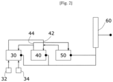
- FIG. 2 illustrates another embodiment of an air system according to the invention in which the central computer 20 is no longer necessary.
- valve 40 is the master valve which acts as a central computer and valves 30 and 50 are slave valves controlled by the master valve 40.
- the different valves are interconnected by digital communication buses 42, 44, which are for example CAN buses.
- the data communication bus 44 is the so-called descending communication bus, making it possible to convey control data from the master valve 40 to the slave control valves 30, 50.
- the data communication bus 42 is the communication bus, called uplink, making it possible to convey data from the slave valves 30, 50 to the master valve 40.
- the regulation valve 30 is connected to analog sensors 32, 34 such that the assembly formed by the regulation valve 30 and the sensors 32, 34 constitutes a local regulation subsystem.
- FIG. 3 schematically illustrates a smart control valve according to one embodiment of the invention making it possible to form the air systems according to the invention.
- FIG 3 illustrates more specifically the control valve 30. This being said, the technical teachings apply mutatis mutandis to the control valves 40 and 50.
- control valve according to a system according to the invention is the presence of an integrated actuator comprising at least an electric motor, an electronic card and on-board software.
- the actuator of the smart valve comprises an electronic card 100 configured to be supplied with electrical energy by the electrical circuit 60.
- the card is further equipped with ports (represented on the left of the electronic card 100) allowing the card to receive data from analog sensors 32, 34, connect the card to CAN communication buses 22 and 24 (depending on the embodiment of the figure 1 ), to configure the card using an input 31 of the “pinprog” type, and to provide discrete information 33 that can be used by the system.
- This card 100 is further configured to control the three phases of a motor 36 which is for example a synchronous motor associated with a means 35 for copying the position of the motor.
- This motor 36 is mechanically connected to a reduction gear 37 which controls the regulating member 38 of the valve 30.
- the electronic card 100 is a card controlled by a microprocessor and comprises for example an input signal filtering module to have signals whose disturbances are limited, a control module formed by the microprocessor, memories, and active components for processing digital and analog signals received at the input of the card, and a power module making it possible to control the electric motor.
- the means 35 for copying the position of the electric motor 36 comprises for example three discrete Hall effect sensors which thus form a position sensor of the electric motor 36.
- Each Hall effect sensor detects variations in the magnetic field which causes its state to vary. 'open to closed, and vice versa, depending on the position of the rotor of the electric motor 36.
- the control module of the electronic card 100 counts the number of activations/deactivations of each Hall effect sensor and deduces a speed.
- This copy of the position of the motor makes it possible to regulate the speed of the electric motor 36 in a closed loop.
- This copy also makes it possible, in connection with the reduction factor of the reducer 37, to determine the position of the regulating member 38 in the pipe within which the regulating valve is arranged.
- the electronic card 100 also embeds software configured to provide the control instructions for the motor 36 (illustrated by the three phases of the motor) based on the control data received as input to the card.
- control data are for example the data conveyed by the downstream CAN bus 24 or the data from the analog sensors 32 and 34.
- This software can be of all types and depends on the control logic targeted by the system according to the invention.
- the software is notably programmed to analyze and decode input data from the digital bus, analog sensors and discrete signals.
- the software is also programmed to analyze position feedback data from the electric motor, to analyze current data from each phase of the motor, and to analyze voltage data from each phase of the electric motor.
- the software is also programmed to monitor different parameters of the electronic board, such as board temperature, board voltage data, and board current data.
- the software embedded on the electronic card can be programmed according to the needs and the desired monitoring indicators within the framework of the targeted application.
Landscapes
- Health & Medical Sciences (AREA)
- General Health & Medical Sciences (AREA)
- Pulmonology (AREA)
- Engineering & Computer Science (AREA)
- Aviation & Aerospace Engineering (AREA)
- Lift Valve (AREA)
- Electrically Driven Valve-Operating Means (AREA)
Abstract
L'invention concerne un système de fluide d'un aéronef comprenant au moins conduite de circulation d'un fluide, au moins une vanne électrique (30, 40, 50) de régulation du flux de fluide dans ladite conduite de fluide par déplacement d'un organe de régulation dans ladite conduite de fluide, un calculateur central (20) configuré pour pouvoir délivrer des instructions de commande à chaque vanne électrique (30, 40, 50) de régulation en fonction des conditions de vol dudit aéronef, et un circuit électrique (60) d'alimentation dudit calculateur et de chaque vanne de régulation électrique, caractérisé en ce qu'au moins vanne de régulation électrique, dite vanne smart, est équipée d'un actionneur intégré relié au calculateur central et/ou à une autre vanne smart du système de fluide par au moins un bus multiplexé de communication de données (22, 24, 42, 44).

Description
L'invention concerne un système de fluide d'un aéronef, tel qu'un système d'air, comprenant au moins une conduite de fluide et au moins une vanne électrique de régulation du flux de fluide dans cette conduite équipée d'un actionneur intégré.The invention relates to a fluid system of an aircraft, such as an air system, comprising at least one fluid pipe and at least one electric valve for regulating the flow of fluid in this pipe equipped with an integrated actuator .
Un aéronef comprend différents types de systèmes de fluide, tel que des systèmes d'air ou des systèmes à cycle vapeur.An aircraft includes different types of fluid systems, such as air systems or vapor cycle systems.
Un système d'air comprend en général une pluralité de conduites d'air et une pluralité de vannes de régulation du flux d'air dans les conduites pour véhiculer l'air depuis des sources d'air vers des équipements consommateurs d'air.An air system generally includes a plurality of air lines and a plurality of air flow control valves in the lines for conveying air from air sources to air consuming equipment.
A titre d'exemple non limitatif, un tel système d'air est par exemple un système de conditionnement d'air d'une cabine de l'aéronef. Un tel système de conditionnement d'air d'une cabine d'aéronef (aussi désigné par la terminologie de « pack de conditionnement d'air ») comprend en général un dispositif de prélèvement d'un air comprimé, plus connu sous la dénomination d'air bleed, sur au moins un compresseur d'un moteur de l'aéronef (tel que par exemple un moteur propulsif ou un moteur auxiliaire de l'aéronef), une turbomachine à cycle à air, des échangeurs de chaleur, un réseau de conduites comprenant des vannes de régulation du flux d'air, et un calculateur central configuré pour pouvoir commander les ouvertures/fermetures des vannes de régulation en fonction des conditions de vol de l'aéronef.By way of non-limiting example, such an air system is for example an air conditioning system of an aircraft cabin. Such an aircraft cabin air conditioning system (also referred to as an “air conditioning pack”) generally comprises a compressed air sampling device, better known under the name of air bleed, on at least one compressor of an engine of the aircraft (such as for example a propulsion engine or an auxiliary engine of the aircraft), an air cycle turbomachine, heat exchangers, a network of pipes comprising air flow regulation valves, and a central computer configured to be able to control the opening/closing of the regulation valves according to the flight conditions of the aircraft.
Le calculateur central du système d'air, connu sous l'acronyme anglais IASC pour « Integrated Air System Controller » est en outre relié à un contrôleur avion pour dialoguer avec ce dernier et recevoir les informations représentatives des conditions de vol de l'aéronef.The central computer of the air system, known by the English acronym IASC for “Integrated Air System Controller”, is also connected to an aircraft controller to communicate with the latter and receive information representative of the flight conditions of the aircraft.
Les vannes électriques d'un tel système d'air comprennent en général un organe d'obturation tel qu'un papillon monté sur un axe perpendiculaire au flux d'air circulant dans la conduite d'air dans laquelle il est agencé. Ce papillon est relié mécaniquement à un réducteur mécanique, entrainé par un moteur électrique à balai ou pas à pas. La commande de ce moteur électrique est déportée dans le calculateur central. Pour ce faire, le calculateur IASC comprend une carte électronique de commande pour chaque vanne électrique.The electric valves of such an air system generally include a shutter member such as a butterfly mounted on an axis perpendicular to the air flow circulating in the air duct in which it is arranged. This butterfly is mechanically connected to a mechanical reducer, driven by a brushed or stepper electric motor. The control of this electric motor is remote in the central computer. To do this, the IASC calculator includes an electronic control card for each electric valve.
Un système d'air d'un aéronef peut comprendre une dizaine de vannes électriques, ce qui implique de disposer d'une dizaine de cartes électroniques agencées dans le calculateur IASC.An aircraft air system can include around ten electrical valves, which requires having around ten electronic cards arranged in the IASC computer.
Il est en outre connu que les différents équipements contrôlés par l'IASC (vannes électriques, vannes électropneumatiques, compresseurs, sondes, ventilateurs, etc.) peuvent soit avoir leur propre alimentation électrique (typiquement une alimentation 28V en courant continue ou une alimentation 115 V en courant alternatif), soit être alimentée par l'IASC.It is also known that the various equipment controlled by the IASC (electric valves, electro-pneumatic valves, compressors, probes, fans, etc.) can either have their own power supply (typically a 28V DC power supply or a 115V power supply in alternating current), or be powered by the IASC.
Un tel système nécessite donc un câblage complexe formé de plusieurs fils électriques qui s'étendent entre le calculateur IASC et chaque équipement électrique.Such a system therefore requires complex wiring made up of several electrical wires which extend between the IASC computer and each electrical item of equipment.
Un tel système n'est donc pas aisément évolutif. En effet, l'ajout d'un équipement ou le déplacement d'un équipement, tel qu'une vanne électrique, impose de modifier le câblage, ce qui peut entrainer une augmentation de la masse du système, une modification des impédances de ligne, un couplage capacitif et inductif entre les différents câbles. L'ajout d'une nouvelle vanne impose en outre d'intégrer une nouvelle carte électronique dans le calculateur IASC.Such a system is therefore not easily scalable. Indeed, adding equipment or moving equipment, such as an electric valve, requires modifying the wiring, which can lead to an increase in the mass of the system, a modification of line impedances, capacitive and inductive coupling between the different cables. Adding a new valve also requires integrating a new electronic card into the IASC computer.
Les inventeurs ont donc cherché à proposer une nouvelle architecture d'un système de fluide, tel qu'un système d'air, qui permet de pallier au moins certains des inconvénients susmentionnés.The inventors have therefore sought to propose a new architecture of a fluid system, such as an air system, which makes it possible to overcome at least some of the aforementioned drawbacks.
L'invention vise à fournir un système de fluide, tel qu'un système d'air, comprenant au moins une conduite de fluide et au moins une vanne électrique de régulation du flux de fluide dans cette conduite.The invention aims to provide a fluid system, such as an air system, comprising at least one fluid pipe and at least one electric valve for regulating the flow of fluid in this pipe.
L'invention vise également à fournir, dans au moins un mode de réalisation, un tel système qui puisse être évolutif sans nécessiter un recâblage complexe de l'ensemble du système.The invention also aims to provide, in at least one embodiment, such a system that can be scalable without requiring complex rewiring of the entire system.
L'invention vise aussi à fournir, dans au moins un mode de réalisation, un tel système qui autorise des modifications du système sans modification du calculateur central du système.The invention also aims to provide, in at least one embodiment, such a system which authorizes modifications to the system without modification of the central computer of the system.
L'invention vise aussi à fournir, dans au moins un mode de réalisation, un tel système qui permet de définir des sous-systèmes locaux, qui allègent la charge du calculateur central du système.The invention also aims to provide, in at least one embodiment, such a system which makes it possible to define local subsystems, which lighten the load on the central computer of the system.
L'invention vise aussi à fournir, dans au moins un mode de réalisation, un tel système qui peut être dénué d'un calculateur central.The invention also aims to provide, in at least one embodiment, such a system which can be devoid of a central computer.
Pour ce faire, l'invention concerne un système de fluide (tel qu'un système d'air ou un système à cycle vapeur) d'un aéronef comprenant au moins conduite de circulation d'un fluide, au moins un équipement électrique de régulation du flux de fluide dans ladite conduite de fluide par déplacement d'un organe de régulation dans ladite conduite de fluide, un calculateur central configuré pour pouvoir délivrer des instructions de commande à chaque équipement électrique de régulation en fonction des conditions de vol dudit aéronef, et un circuit électrique d'alimentation dudit contrôleur central et de chaque équipement électrique de régulation.To do this, the invention relates to a fluid system (such as an air system or a steam cycle system) of an aircraft comprising at least one fluid circulation pipe, at least one electrical regulation equipment of the flow of fluid in said fluid pipe by moving a regulating member in said fluid pipe, a central computer configured to be able to deliver control instructions to each electrical regulation equipment as a function of the flight conditions of said aircraft, and an electrical supply circuit for said central controller and each electrical regulation equipment.
Le système de fluide selon l'invention est caractérisé en ce qu'au moins un équipement électrique de régulation, dit vanne smart, est équipé d'un actionneur intégré relié au calculateur central et/ou à une autre vanne smart du système de fluide par au moins un bus multiplexé de communication de données, dit bus numérique, ledit actionneur intégré comprenant :
- une carte électronique de commande équipée d'au moins un port relié à chaque bus numérique,
- un moteur électrique piloté par ladite carte électronique de commande et configuré pour pouvoir déplacer ledit organe de régulation dans ladite conduite de fluide,
- un logiciel embarqué sur ladite carte électronique de commande et configuré pour pouvoir déterminer des instructions de commande du moteur électrique à partir de données reçues sur au moins un port d'entrée de ladite carte, dites données de pilotage.
- an electronic control card equipped with at least one port connected to each digital bus,
- an electric motor controlled by said electronic control card and configured to be able to move said regulating member in said fluid pipe,
- software embedded on said electronic control card and configured to be able to determine instructions for controlling the electric motor from data received on at least one input port of said card, called control data.
Un système selon l'invention peut former soit un système d'air (dans le cas où le fluide est de l'air), soit un système à cycle vapeur (dans le cas où le fluide est un fluide diphasique). Dans toute la suite, le système est décrit dans sa version « système d'air ». Cela étant, l'homme du métier comprendra aisément que les enseignements s'appliquent mutatis mutandis à un système à cycle vapeur ou à tout système de fluide d'un aéronef comprenant des conduites de fluide et des vannes de régulation du flux de fluide dans ces conduites.A system according to the invention can form either an air system (in the case where the fluid is air) or a vapor cycle system (in the case where the fluid is a two-phase fluid). In the following, the system is described in its “air system” version. This being said, those skilled in the art will easily understand that the teachings apply mutatis mutandis to a steam cycle system or to any fluid system of an aircraft comprising fluid pipes and valves for regulating the flow of fluid in these. conducts.
Les équipements électriques de régulation peuvent être de tous types. Il peut s'agir de vannes électriques, de vannes électropneumatiques, de compresseurs, de ventilateurs, etc. Dans toute la suite, on évoque essentiellement des vannes électriques de régulation, étant entendu que l'invention ne se limite pas aux seules vannes électriques de régulation. L'homme du métier comprendra aisément que les enseignements s'appliquent mutatis mutandis à un système comprenant d'autres types d'équipements électriques de régulation tels que ceux susmentionnés.Electrical regulation equipment can be of all types. These can be electric valves, electro-pneumatic valves, compressors, fans, etc. Throughout what follows, we mainly mention electric control valves, it being understood that the invention is not limited to electric control valves alone. Those skilled in the art will easily understand that the teachings apply mutatis mutandis to a system comprising other types of electrical regulation equipment such as those mentioned above.
Le système selon l'invention présente notamment la particularité d'avoir déporté le contrôle des moteurs de chaque vanne électrique de régulation directement dans chaque vanne, formant ainsi une vanne smart.The system according to the invention has the particularity of having deported the control of the motors of each electric regulation valve directly into each valve, thus forming a smart valve.
En outre, chaque vanne smart peut être reliée au calculateur central et/ou à une autre vanne smart par au moins un bus numérique, de préférence deux bus numérique unidirectionnel. En d'autres termes et dans le cas de deux bus numériques unidirectionnels, destinés respectivement aux liaisons montantes (les données sont envoyées par le calculateur central et/ou par une autre vanne smart à destination de cette vanne smart) et descentes (les données sont envoyées par cette vanne smart à destination du calculateur central et/ou d'une autre vanne smart), seuls deux fils sont nécessaires entre le calculateur et/ou une vanne smart et cette vanne smart. Il est aussi possible de relier les vannes entre elles et/ou les vannes et le calculateur par deux bus numériques bidirectionnels.In addition, each smart valve can be connected to the central computer and/or to another smart valve by at least one digital bus, preferably two unidirectional digital buses. In other words and in the case of two unidirectional digital buses, intended respectively for uplinks (the data are sent by the central computer and/or by another smart valve to this smart valve) and downlinks (the data are sent by this smart valve to the central computer and/or another smart valve), only two wires are necessary between the computer and/or a smart valve and this smart valve. It is also possible to connect the valves to each other and/or the valves and the computer via two bidirectional digital buses.
Un bus numérique est de préférence un bus de données faisant référence à la désignation anglaise de Controller Area Network (plus connu sous la dénomination de bus CAN). Ce bus multiplexé permet de raccorder sur un même câble l'ensemble des vannes électriques au calculateur central, limitant ainsi les câblages spécifiques entre le calculateur central et chaque équipement électrique de régulation.A digital bus is preferably a data bus referring to the English designation of Controller Area Network (better known as CAN bus). This multiplexed bus makes it possible to connect all the electrical valves to the central computer on the same cable, thus limiting the specific wiring between the central computer and each electrical control equipment.
Un système selon l'invention est donc aisément évolutif dans la mesure où il suffit de relier un nouvel équipement électrique de régulation aux bus de communications numériques et à une alimentation électrique pour qu'il puisse être mis en service, sans nécessiter de faire évoluer en parallèle le calculateur central et/ou l'ensemble du câblage du système.A system according to the invention is therefore easily scalable to the extent that it suffices to connect new electrical regulation equipment to the digital communications buses and to a power supply so that it can be put into service, without requiring it to be upgraded in time. parallel the central computer and/or all of the system wiring.
Selon l'invention, la carte électronique reçoit des données de pilotage à partir desquelles des instructions de commande moteur sont élaborées. Les données de pilotage peuvent provenir du calculateur central et sont véhiculées par le bus numérique descendant.According to the invention, the electronic card receives control data from which motor control instructions are developed. The control data can come from the central computer and are conveyed by the downlink digital bus.
Avantageusement et selon l'invention, au moins une vanne smart est reliée à au moins un capteur analogique de mesure d'une grandeur de fluide véhiculé par la conduite de fluide associée et ladite carte électronique de cette vanne smart comprend au moins un port d'entrée relié à ce capteur analogique de telle sorte que les mesures fournies par ce capteur analogique puissent former des données de pilotage.Advantageously and according to the invention, at least one smart valve is connected to at least one analog sensor for measuring a quantity of fluid conveyed by the associated fluid pipe and said electronic card of this smart valve comprises at least one port. input connected to this analog sensor so that the measurements provided by this analog sensor can form control data.
Selon cette variante, une vanne smart peut recevoir, à titre de données pilotage, des mesures d'une grandeur du fluide véhiculé par la conduite dont elle contrôle le flux. Ainsi, cet ensemble formé d'une vanne smart et d'un ou plusieurs capteurs analogiques peut former un sous-système de régulation locale, tel qu'un sous-système de régulation de pression, de température ou de débit, en fonction du type de capteur utilisé.According to this variant, a smart valve can receive, as control data, measurements of a quantity of the fluid conveyed by the pipe whose flow it controls. Thus, this assembly formed of a smart valve and one or more analog sensors can form a local regulation subsystem, such as a pressure, temperature or flow regulation subsystem, depending on the type. of sensor used.
Cette variante permet donc d'alléger la charge du calculateur central du système de fluide en déportant une partie de la régulation au sous-système local ainsi formé. Cela permet donc de réduire la masse globale du système de fluide en limitant les câblages et en réduisant les besoins du calculateur central (une partie de ses fonctionnalités étant alors déportées dans les sous-systèmes locaux ainsi formés).This variant therefore makes it possible to lighten the load on the central computer of the fluid system by transferring part of the regulation to the local subsystem thus formed. This therefore makes it possible to reduce the overall mass of the fluid system by limiting wiring and reducing the needs of the central computer (part of its functionalities then being transferred to the local subsystems thus formed).
Avantageusement et selon l'invention, le système comprend au moins deux vannes smart reliées entre elles par un bus numérique, ladite première vanne smart, dite vanne maître, étant configurée pour pouvoir déterminer et transmettre des données de pilotage à ladite deuxième vanne smart, dite vanne esclave.Advantageously and according to the invention, the system comprises at least two smart valves connected together by a digital bus, said first smart valve, called master valve, being configured to be able to determine and transmit control data to said second smart valve, called slave valve.
Selon cette variante avantageuse, l'actionneur de la vanne maître fait office de calculateur central pour la vanne esclave. En d'autres termes et selon cette variante, le calculateur central n'est pas nécessaire et la vanne maître peut remplacer le calculateur central. Les vannes smarts sont reliées entre elles par les bus de données numériques. Un tel système peut être utilisé en lieu et place des systèmes nécessitant peu d'équipements de régulation, comme les systèmes de régulation de température pour hélicoptère.According to this advantageous variant, the actuator of the master valve acts as a central computer for the slave valve. In other words and according to this variant, the central computer is not necessary and the master valve can replace the central computer. The smart valves are connected to each other via digital data buses. Such a system can be used in place of systems requiring little control equipment, such as temperature control systems for helicopters.
A noter que les vannes esclaves d'un tel système peuvent également former un sous-système de régulation locale lorsqu'elles sont reliées à un capteur analogique de mesure d'une grandeur de fluide comme décrit précédemment.Note that the slave valves of such a system can also form a local regulation subsystem when they are connected to an analog sensor for measuring a fluid quantity as described previously.
Un système de fluide selon l'invention peut être un système d'air d'un aéronef lorsque le fluide est de l'air. Un tel système d'air est par exemple un système de conditionnement d'air d'un aéronef.A fluid system according to the invention can be an air system of an aircraft when the fluid is air. Such an air system is for example an air conditioning system of an aircraft.
Un système de fluide selon l'invention peut également être un système à cycle vapeur lorsque le fluide est un fluide diphasique.A fluid system according to the invention can also be a vapor cycle system when the fluid is a two-phase fluid.
Selon d'autres aspects de l'invention, l'actionneur d'une vanne smart selon l'invention peut comprendre une ou plusieurs des caractéristiques techniques suivantes :
- le moteur électrique est un moteur synchrone comprenant des moyens de recopie de sa position,
- un réducteur relie mécaniquement ledit moteur électrique et ledit organe de régulation,
- la logiciel embarqué sur la carte électronique est configuré pour surveiller la vanne smart et gérer les pannes de l'actionneur,
- le logiciel embarqué est configurable pour conférer à la vanne un rôle de sous-système de régulation locale par des entrées du type « pinprog » prévues sur la carte électronique.
- the electric motor is a synchronous motor comprising means for copying its position,
- a reduction gear mechanically connects said electric motor and said regulating member,
- the software embedded on the electronic card is configured to monitor the smart valve and manage actuator failures,
- the on-board software can be configured to give the valve the role of a local regulation subsystem using “pinprog” type inputs provided on the electronic card.
L'invention concerne également un système de fluide caractérisé en combinaison par tout ou partie des caractéristiques mentionnées ci-dessus ou ci-après.The invention also relates to a fluid system characterized in combination by all or part of the characteristics mentioned above or below.
D'autres buts, caractéristiques et avantages de l'invention apparaîtront à la lecture de la description suivante donnée à titre uniquement non limitatif et qui se réfère aux figures annexées dans lesquelles :
- [
Fig. 1 ] est une vue schématique d'un système d'air selon un premier mode de réalisation de l'invention, - [
Fig. 2 ] est une vue schématique d'un système d'air selon un deuxième mode de réalisation de l'invention, - [
Fig. 3 ] est une vue schématique fonctionnelle d'une vanne smart d'un système d'air selon l'invention.
- [
Fig. 1 ] is a schematic view of an air system according to a first embodiment of the invention, - [
Fig. 2 ] is a schematic view of an air system according to a second embodiment of the invention, - [
Fig. 3 ] is a functional schematic view of a smart valve of an air system according to the invention.
Sur les figures, les échelles et les proportions ne sont pas strictement respectées et ce, à des fins d'illustration et de clarté. En outre, les éléments identiques, similaires ou analogues sont désignés par les mêmes références dans toutes les figures.In the figures, scales and proportions are not strictly respected for purposes of illustration and clarity. In addition, identical, similar or analogous elements are designated by the same references in all the figures.
La
Le système d'air selon le mode de réalisation de la
Le calculateur central 20 est relié aux vannes 30, 40, 50 par deux bus de communication de données 22, 24. Le bus de communication de données 24 est le bus de communication, dit descendant, permettant de véhiculer des données de pilotage du calculateur central 20 vers les vannes de régulation. Le bus de communication de données 22 est le bus de communication, dit montant, permettant de véhiculer des données (par exemple la position des vannes ou autres informations disponibles) des vannes 30, 40, 50 vers le calculateur central 20.The
Le système selon le mode de réalisation de la
Enfin, l'ensemble des équipements électriques du système selon l'invention sont alimentés par un circuit électrique 60, qui est par exemple un circuit avion 28 volts.Finally, all of the electrical equipment of the system according to the invention is powered by an
La
Ainsi, dans ce mode de réalisation, seules les trois vannes smarts 30, 40, 50 sont présentes. En outre, la vanne 40 est la vanne maître qui fait office de calculateur central et les vannes 30 et 50 sont des vannes esclaves pilotées par la vanne maître 40. Les différentes vannes sont reliées entre elles par des bus de communication numériques 42, 44, qui sont par exemple des bus CAN. Le bus de communication de données 44 est le bus de communication, dit descendant, permettant de véhiculer des données de pilotage de la vanne maître 40 vers les vannes de régulation esclaves 30, 50. Le bus de communication de données 42 est le bus de communication, dit montant, permettant de véhiculer des données des vannes esclaves 30, 50 vers la vanne maître 40.Thus, in this embodiment, only the three
En outre, et à l'instar du mode de réalisation de la
La
La particularité d'une vanne de régulation selon un système selon l'invention est la présence d'un actionneur intégré comprenant a minima un moteur électrique, une carte électronique et un logiciel embarqué.The particularity of a control valve according to a system according to the invention is the presence of an integrated actuator comprising at least an electric motor, an electronic card and on-board software.
Sur la
Cette carte 100 est en outre configurée pour piloter les trois phases d'un moteur 36 qui est par exemple un moteur synchrone associé à un moyen de recopie 35 de la position du moteur. Ce moteur 36 est relié mécaniquement à un réducteur 37 qui pilote l'organe de régulation 38 de la vanne 30.This
La carte électronique 100 est une carte pilotée par un microprocesseur et comprend par exemple un module de filtrage des signaux d'entrées pour disposer de signaux dont les perturbations sont limitées, un module de contrôle formé par le microprocesseur, des mémoires, et des composants actifs de traitement des signaux numériques et analogiques reçus en entrée de la carte, et un module de puissance permettant de contrôler le moteur électrique.The
Le moyen de recopie 35 de la position du moteur électrique 36 comprend par exemple trois capteurs à effet Hall discrets qui forment ainsi un capteur de position du moteur électrique 36. Chaque capteur à effet Hall détecte les variations du champ magnétique qui fait varier sont état d'ouvert à fermé, et inversement, en fonction de la position du rotor du moteur électrique 36. Le module de contrôle de la carte électronique 100 compte le nombre d'activation/désactivation de chaque capteur à effet Hall et en déduit une vitesse.The means 35 for copying the position of the
Cette recopie de la position du moteur permet de réguler la vitesse du moteur électrique 36 en boucle fermée. Cette recopie permet également, en lien avec le facteur de réduction du réducteur 37, de déterminer la position de l'organe de régulation 38 dans la conduite au sein de laquelle la vanne de régulation est agencée.This copy of the position of the motor makes it possible to regulate the speed of the
La carte électronique 100 embarque en outre un logiciel configuré pour fournir les instructions de commande du moteur 36 (illustrées par les trois phases du moteur) en fonction des données de pilotage reçues en entrée de la carte. Ces données de pilotage sont par exemple les données véhiculées par le bus CAN descendant 24 ou les données issues des capteurs analogique 32 et 34.The
Ce logiciel peut être de tous types et dépend des logiques de commande visées par le système selon l'invention.This software can be of all types and depends on the control logic targeted by the system according to the invention.
Le logiciel est notamment programmé pour analyser et décoder les données d'entrées issues du bus numérique, des capteurs analogiques et des signaux discrets. Le logiciel est également programmé pour analyser les données de retour de position du moteur électrique, pour analyser les données de courant de chaque phase du moteur et pour analyser les données de tension de chaque phase du moteur électrique.The software is notably programmed to analyze and decode input data from the digital bus, analog sensors and discrete signals. The software is also programmed to analyze position feedback data from the electric motor, to analyze current data from each phase of the motor, and to analyze voltage data from each phase of the electric motor.
Le logiciel est également programmé pour surveiller différents paramètres de la carte électronique, tels que la température de la carte, les données de tension de la carte et les données de courant de la carte.The software is also programmed to monitor different parameters of the electronic board, such as board temperature, board voltage data, and board current data.
D'une manière générale, le logiciel embarqué sur la carte électronique peut être programmé selon les besoins et les indicateurs de suivi souhaité dans le cadre de l'application visée.Generally speaking, the software embedded on the electronic card can be programmed according to the needs and the desired monitoring indicators within the framework of the targeted application.
Claims (8)
caractérisé en ce qu'au moins une vanne de régulation électrique, dite vanne smart, est équipée d'un actionneur intégré relié au calculateur central et/ou à une autre vanne smart du système de fluide par au moins un bus multiplexé de communication de données, dit bus numérique (22, 24, 42, 44), ledit actionneur intégré comprenant:
characterized in that at least one electrical control valve, called a smart valve, is equipped with an integrated actuator connected to the central computer and/or to another smart valve of the fluid system by at least one multiplexed data communication bus , called digital bus (22, 24, 42, 44), said integrated actuator comprising:
Applications Claiming Priority (1)
| Application Number | Priority Date | Filing Date | Title |
|---|---|---|---|
| FR2205953A FR3136824A1 (en) | 2022-06-17 | 2022-06-17 | AIRCRAFT FLUID SYSTEM COMPRISING AN ELECTRIC REGULATION VALVE EQUIPPED WITH AN INTEGRATED ACTUATOR |
Publications (1)
| Publication Number | Publication Date |
|---|---|
| EP4292936A1 true EP4292936A1 (en) | 2023-12-20 |
Family
ID=83438900
Family Applications (1)
| Application Number | Title | Priority Date | Filing Date |
|---|---|---|---|
| EP23179108.8A Pending EP4292936A1 (en) | 2022-06-17 | 2023-06-14 | Aircraft fluid system including an electric control valve equipped with an integrated actuator |
Country Status (2)
| Country | Link |
|---|---|
| EP (1) | EP4292936A1 (en) |
| FR (1) | FR3136824A1 (en) |
Citations (4)
| Publication number | Priority date | Publication date | Assignee | Title |
|---|---|---|---|---|
| WO2003072432A2 (en) * | 2002-02-21 | 2003-09-04 | Honeywell International Inc. | Instrumentation and control circuit having multiple, dissimilar sources for supplying warnings, indications and controls, and an integrated cabin pressure control system valve incorporating the same |
| EP1619121A1 (en) * | 2004-07-22 | 2006-01-25 | Honeywell International Inc. | Cabin pressure control system and method |
| US20150168000A1 (en) * | 2013-12-17 | 2015-06-18 | Ian Robert Dempster | Systems and methods for using a smart valve to control conditioned air |
| EP3395688A1 (en) * | 2017-04-27 | 2018-10-31 | Hamilton Sundstrand Corporation | Configurable high rate closed loop smart valve control |
-
2022
- 2022-06-17 FR FR2205953A patent/FR3136824A1/en active Pending
-
2023
- 2023-06-14 EP EP23179108.8A patent/EP4292936A1/en active Pending
Patent Citations (4)
| Publication number | Priority date | Publication date | Assignee | Title |
|---|---|---|---|---|
| WO2003072432A2 (en) * | 2002-02-21 | 2003-09-04 | Honeywell International Inc. | Instrumentation and control circuit having multiple, dissimilar sources for supplying warnings, indications and controls, and an integrated cabin pressure control system valve incorporating the same |
| EP1619121A1 (en) * | 2004-07-22 | 2006-01-25 | Honeywell International Inc. | Cabin pressure control system and method |
| US20150168000A1 (en) * | 2013-12-17 | 2015-06-18 | Ian Robert Dempster | Systems and methods for using a smart valve to control conditioned air |
| EP3395688A1 (en) * | 2017-04-27 | 2018-10-31 | Hamilton Sundstrand Corporation | Configurable high rate closed loop smart valve control |
Also Published As
| Publication number | Publication date |
|---|---|
| FR3136824A1 (en) | 2023-12-22 |
Similar Documents
| Publication | Publication Date | Title |
|---|---|---|
| EP2195240B1 (en) | Fadec and avionic component distributed architecture | |
| EP1953085B1 (en) | Circuit for supplying electricity to the electrical equipment in an aircraft including an de-icing circuit | |
| EP1685025B1 (en) | Aircraft fluid cooling system and an aircraft provided with said system | |
| EP1852347B1 (en) | System for powering and controlling electrical equipment of an aircraft motor or of its environment | |
| EP1849225B1 (en) | Electric supply for an aircraft gas turbine engine equipment | |
| CA2818066C (en) | Control process and regulation system for supplying compressed air to a compressed air network, specifically in an aircraft | |
| FR2533530A2 (en) | INTEGRATED ASSEMBLY COMPRISING AN AUXILIARY ENGINE GROUP AND A PACKAGING APPARATUS FOR AN AIRCRAFT | |
| WO2018069637A1 (en) | System for powering and controlling electrically controlled actuators installed in an aircraft | |
| EP3377733B1 (en) | System and method for supplying lubrication fluid to at least one member of an aircraft propulsion assembly | |
| FR3010387A1 (en) | AIRCRAFT COMPRISING A DEVICE FOR CONTROLLING A VARIABLE SECTION TUBE SUPPLIED BY TWO INDEPENDENT ELECTRICAL SUPPLIES | |
| FR2742805A1 (en) | ENGINE RESTART ASSISTANCE SYSTEM AFTER TOTAL LOSS OF MOTORIZATION | |
| EP3953206B1 (en) | Hybrid propulsive installation and method for controlling such an installation | |
| EP3505402B1 (en) | Electrical harness | |
| FR3062422A1 (en) | FUEL SUPPLY SYSTEM OF A TURBOMACHINE | |
| EP3483063B1 (en) | Architecture of an aircraft braking system | |
| EP4292936A1 (en) | Aircraft fluid system including an electric control valve equipped with an integrated actuator | |
| EP3342709A1 (en) | Method and device for environmental control of an aircraft supplied with bleed air at intermediate pressure | |
| WO2022200088A1 (en) | System and method for controlling the modification of the pitch of the blades of a turbine engine | |
| EP3390229B1 (en) | Hydraulic control system for a thrust reverser comprising a data concentrator module | |
| FR3110137A1 (en) | Distributed aircraft braking system architecture | |
| EP3947151B1 (en) | Environmental control sytem using two turbomachines | |
| EP3969363B1 (en) | Turbomachine comprising a system for deicing the front cone, and associated method | |
| EP3951149A1 (en) | Method for managing the drawing of power generated by an auxiliary power unit of an aircraft and aircraft provided with said device for managing drawing of power | |
| FR3116397A1 (en) | Actuator power and control system | |
| FR3138927A1 (en) | Positioning of an air intake port of a turbomachine |
Legal Events
| Date | Code | Title | Description |
|---|---|---|---|
| PUAI | Public reference made under article 153(3) epc to a published international application that has entered the european phase |
Free format text: ORIGINAL CODE: 0009012 |
|
| STAA | Information on the status of an ep patent application or granted ep patent |
Free format text: STATUS: THE APPLICATION HAS BEEN PUBLISHED |
|
| AK | Designated contracting states |
Kind code of ref document: A1 Designated state(s): AL AT BE BG CH CY CZ DE DK EE ES FI FR GB GR HR HU IE IS IT LI LT LU LV MC ME MK MT NL NO PL PT RO RS SE SI SK SM TR |