EP4277119A1 - Bracket system for photovoltaic module - Google Patents
Bracket system for photovoltaic module Download PDFInfo
- Publication number
- EP4277119A1 EP4277119A1 EP23722805.1A EP23722805A EP4277119A1 EP 4277119 A1 EP4277119 A1 EP 4277119A1 EP 23722805 A EP23722805 A EP 23722805A EP 4277119 A1 EP4277119 A1 EP 4277119A1
- Authority
- EP
- European Patent Office
- Prior art keywords
- photovoltaic assembly
- connecting portion
- lower connecting
- limiting groove
- support system
- Prior art date
- Legal status (The legal status is an assumption and is not a legal conclusion. Google has not performed a legal analysis and makes no representation as to the accuracy of the status listed.)
- Pending
Links
- 239000002390 adhesive tape Substances 0.000 claims description 5
- 238000010586 diagram Methods 0.000 description 8
- 238000009434 installation Methods 0.000 description 5
- 239000000463 material Substances 0.000 description 5
- 239000004568 cement Substances 0.000 description 4
- 238000004519 manufacturing process Methods 0.000 description 4
- VYPSYNLAJGMNEJ-UHFFFAOYSA-N Silicium dioxide Chemical compound O=[Si]=O VYPSYNLAJGMNEJ-UHFFFAOYSA-N 0.000 description 2
- 230000000712 assembly Effects 0.000 description 2
- 238000000429 assembly Methods 0.000 description 2
- 238000006073 displacement reaction Methods 0.000 description 2
- 230000000694 effects Effects 0.000 description 2
- 239000000741 silica gel Substances 0.000 description 2
- 229910002027 silica gel Inorganic materials 0.000 description 2
- 229910000838 Al alloy Inorganic materials 0.000 description 1
- 229910000881 Cu alloy Inorganic materials 0.000 description 1
- 239000000956 alloy Substances 0.000 description 1
- 230000005611 electricity Effects 0.000 description 1
- 229920006351 engineering plastic Polymers 0.000 description 1
- 238000005516 engineering process Methods 0.000 description 1
- 230000014509 gene expression Effects 0.000 description 1
- 238000011900 installation process Methods 0.000 description 1
- 230000003993 interaction Effects 0.000 description 1
- 230000000670 limiting effect Effects 0.000 description 1
- 238000010248 power generation Methods 0.000 description 1
- 229910001220 stainless steel Inorganic materials 0.000 description 1
- 230000003068 static effect Effects 0.000 description 1
Images


Classifications
-
- H—ELECTRICITY
- H02—GENERATION; CONVERSION OR DISTRIBUTION OF ELECTRIC POWER
- H02S—GENERATION OF ELECTRIC POWER BY CONVERSION OF INFRARED RADIATION, VISIBLE LIGHT OR ULTRAVIOLET LIGHT, e.g. USING PHOTOVOLTAIC [PV] MODULES
- H02S20/00—Supporting structures for PV modules
- H02S20/20—Supporting structures directly fixed to an immovable object
- H02S20/22—Supporting structures directly fixed to an immovable object specially adapted for buildings
- H02S20/23—Supporting structures directly fixed to an immovable object specially adapted for buildings specially adapted for roof structures
- H02S20/24—Supporting structures directly fixed to an immovable object specially adapted for buildings specially adapted for roof structures specially adapted for flat roofs
-
- H—ELECTRICITY
- H02—GENERATION; CONVERSION OR DISTRIBUTION OF ELECTRIC POWER
- H02S—GENERATION OF ELECTRIC POWER BY CONVERSION OF INFRARED RADIATION, VISIBLE LIGHT OR ULTRAVIOLET LIGHT, e.g. USING PHOTOVOLTAIC [PV] MODULES
- H02S20/00—Supporting structures for PV modules
- H02S20/30—Supporting structures being movable or adjustable, e.g. for angle adjustment
-
- F—MECHANICAL ENGINEERING; LIGHTING; HEATING; WEAPONS; BLASTING
- F24—HEATING; RANGES; VENTILATING
- F24S—SOLAR HEAT COLLECTORS; SOLAR HEAT SYSTEMS
- F24S25/00—Arrangement of stationary mountings or supports for solar heat collector modules
- F24S25/10—Arrangement of stationary mountings or supports for solar heat collector modules extending in directions away from a supporting surface
- F24S25/16—Arrangement of interconnected standing structures; Standing structures having separate supporting portions for adjacent modules
-
- H—ELECTRICITY
- H02—GENERATION; CONVERSION OR DISTRIBUTION OF ELECTRIC POWER
- H02S—GENERATION OF ELECTRIC POWER BY CONVERSION OF INFRARED RADIATION, VISIBLE LIGHT OR ULTRAVIOLET LIGHT, e.g. USING PHOTOVOLTAIC [PV] MODULES
- H02S20/00—Supporting structures for PV modules
- H02S20/10—Supporting structures directly fixed to the ground
-
- H—ELECTRICITY
- H02—GENERATION; CONVERSION OR DISTRIBUTION OF ELECTRIC POWER
- H02S—GENERATION OF ELECTRIC POWER BY CONVERSION OF INFRARED RADIATION, VISIBLE LIGHT OR ULTRAVIOLET LIGHT, e.g. USING PHOTOVOLTAIC [PV] MODULES
- H02S20/00—Supporting structures for PV modules
- H02S20/20—Supporting structures directly fixed to an immovable object
- H02S20/22—Supporting structures directly fixed to an immovable object specially adapted for buildings
- H02S20/23—Supporting structures directly fixed to an immovable object specially adapted for buildings specially adapted for roof structures
-
- F—MECHANICAL ENGINEERING; LIGHTING; HEATING; WEAPONS; BLASTING
- F24—HEATING; RANGES; VENTILATING
- F24S—SOLAR HEAT COLLECTORS; SOLAR HEAT SYSTEMS
- F24S25/00—Arrangement of stationary mountings or supports for solar heat collector modules
- F24S2025/01—Special support components; Methods of use
- F24S2025/013—Stackable support elements
-
- Y—GENERAL TAGGING OF NEW TECHNOLOGICAL DEVELOPMENTS; GENERAL TAGGING OF CROSS-SECTIONAL TECHNOLOGIES SPANNING OVER SEVERAL SECTIONS OF THE IPC; TECHNICAL SUBJECTS COVERED BY FORMER USPC CROSS-REFERENCE ART COLLECTIONS [XRACs] AND DIGESTS
- Y02—TECHNOLOGIES OR APPLICATIONS FOR MITIGATION OR ADAPTATION AGAINST CLIMATE CHANGE
- Y02E—REDUCTION OF GREENHOUSE GAS [GHG] EMISSIONS, RELATED TO ENERGY GENERATION, TRANSMISSION OR DISTRIBUTION
- Y02E10/00—Energy generation through renewable energy sources
- Y02E10/40—Solar thermal energy, e.g. solar towers
- Y02E10/47—Mountings or tracking
-
- Y—GENERAL TAGGING OF NEW TECHNOLOGICAL DEVELOPMENTS; GENERAL TAGGING OF CROSS-SECTIONAL TECHNOLOGIES SPANNING OVER SEVERAL SECTIONS OF THE IPC; TECHNICAL SUBJECTS COVERED BY FORMER USPC CROSS-REFERENCE ART COLLECTIONS [XRACs] AND DIGESTS
- Y02—TECHNOLOGIES OR APPLICATIONS FOR MITIGATION OR ADAPTATION AGAINST CLIMATE CHANGE
- Y02E—REDUCTION OF GREENHOUSE GAS [GHG] EMISSIONS, RELATED TO ENERGY GENERATION, TRANSMISSION OR DISTRIBUTION
- Y02E10/00—Energy generation through renewable energy sources
- Y02E10/50—Photovoltaic [PV] energy
Definitions
- the present application relates to the technical field of photovoltaic assemblies, for example, to a photovoltaic assembly support system.
- the photovoltaic assembly is typically mounted on a support system to allow the support system to support the photovoltaic assembly, so as to enable the photovoltaic assembly to be at a certain angle with respect to the ground or a roof plane, and to increase the area of the photovoltaic assembly directly irradiated by the sunlight and improve the efficiency of power generation.
- the support system in the related art supports the photovoltaic assembly
- it is required to additionally use an upright post to support the photovoltaic assembly, which further increases the processing and manufacturing cost of the photovoltaic assembly support system, and reduces the assembly efficiency.
- the distance between two adjacent track supports in the support system cannot be adjusted, that is, the distance between two track supports is equal to the length of the photovoltaic assembly, so that the photovoltaic assembly is apt to be obviously bent and deformed when being subjected to a large mechanical load, and may be damaged when in a severe case.
- a photovoltaic assembly support system is provided according to the present application, the photovoltaic assembly support system has a simple structure, is easy to assemble and disassemble, and does not require an additional supporting component such as an upright post, thereby reducing the installation difficulty, saving the manufacturing cost, and improving the working efficiency of installing a photovoltaic assembly body.
- a photovoltaic assembly support system is provided according to the present application.
- the photovoltaic assembly support system is configured to support a photovoltaic assembly body.
- the photovoltaic assembly support system includes a support body, multiple lower connecting members, and an upper connecting member.
- the multiple lower connecting members are arranged on the support body.
- the upper connecting member includes a first position-limiting groove and a second position-limiting groove, the first position-limiting groove and the multiple lower connecting members are arranged to enable the photovoltaic assembly body to be clamped between the first position-limiting groove and the multiple lower connecting members, and/or the second position-limiting groove and the multiple lower connecting members are arranged to enable the photovoltaic assembly body to be clamped between the second position-limiting groove and the multiple lower connecting members.
- connection to each other is to be construed in a broad sense, for example, as securely connected, detachably connected, or integrated; mechanically connected or electrically connected; directly connected to each other, indirectly connected to each other via an intermediary, internal connection between two components, or interaction between two components.
- connection is to be construed in a broad sense, for example, as securely connected, detachably connected, or integrated; mechanically connected or electrically connected; directly connected to each other, indirectly connected to each other via an intermediary, internal connection between two components, or interaction between two components.
- a first feature being “on” or “under” a second feature may include the first feature and the second feature being in direct contact, or may include the first feature and the second feature not being in direct contact but being in contact with each other through an additional feature therebetween.
- the first feature being "on”, “above” or “over” the second feature includes the first feature being directly on, above or over and obliquely on, above or over the second feature, or simply indicates that the first feature is at a higher level than the second feature.
- the first feature being "under”, “below” or “underneath” the second feature includes the first feature being directly under, below or underneath and obliquely under, below or underneath the second feature, or simply represents that the first feature is at a lower level than the second feature.
- orientational or positional relationships indicated by terms “above”, “below”, “left”, “right”, and the like are based on the orientational or positional relationships shown in the drawings, and are merely for ease of description and simplifying an operation, rather than indicating or implying that the referred device or element must have a specific orientation and be constructed and operated in a specific orientation.
- first and second are used only to distinguish between descriptions and have no special meaning.
- a photovoltaic assembly support system for supporting a photovoltaic assembly body 100.
- the photovoltaic assembly support system mainly includes a support body 200, a lower connecting member 400 and an upper connecting member 300. Multiple lower connecting members 400 are provided, and the multiple lower connecting members 400 are arranged on the support body 200.
- the upper connecting member 300 includes a first position-limiting groove 310 and a second position-limiting groove 320, and the first position-limiting groove 310 and the lower connecting members 400 are arranged to enable the photovoltaic assembly body 100 to be clamped between the first position-limiting groove 310 and the lower connecting members 400, and/or the second position-limiting groove 320 and the lower connecting members 400 are arranged to enable the photovoltaic assembly body 100 to be clamped between the second position-limiting groove 320 and the lower connecting members 400.
- the operator may clamp the photovoltaic assembly bodies 100 between the first position-limiting grooves 310 and the lower connecting members 400, or clamp the photovoltaic assembly bodies 100 between the second position-limiting grooves 320 and the lower connecting members 400, so that each row of photovoltaic assembly bodies 100 forms a character " - "-shaped structure.
- the operator may clamp columns of the even number of photovoltaic assembly bodies 100 between the first position-limiting grooves 310 and the lower connecting members 400 and between the second position-limiting grooves 320 and the lower connecting members 400, respectively, so that each two rows of photovoltaic assembly bodies 100 form a character "A" -shaped structure, thereby improving the flexibility and applicability of the photovoltaic assembly support system.
- multiple support bodies 200, multiple lower connecting members 400, and multiple upper connecting members 300 in this embodiment may be provided, and the operator may adjust distances between the multiple support bodies 200 according to practical requirements, thereby improving the stability and reliability of the photovoltaic assembly bodies 100, so that the photovoltaic assembly bodies 100 are not apt to be severely deformed when subjected to a large mechanical load.
- a distance between the support body 200 and a short side of the photovoltaic assembly body 100 ranges from one fourth to one fifth of a long side of the photovoltaic assembly body 100.
- two support bodies 200 are flush with the short sides of the photovoltaic assembly bodies 100, in this way, the photovoltaic assembly bodies 100 are prevented from injuring the operator due to protruding from the support body 200, and moreover, the aesthetics of the whole photovoltaic assembly system can be improved.
- the photovoltaic assembly body 100 in this embodiment includes a photovoltaic assembly panel, an upper frame 110 and a lower frame 120.
- the photovoltaic assembly panel is embedded between the upper frame 110 and the lower frame 120, and the upper frame 110 is arranged to be engaged by the upper connecting member 300, and the lower frame 120 is arranged to be engaged by the lower connecting members 400, thereby achieving the stable connection between the photovoltaic assembly body 100 and the photovoltaic assembly support system.
- the support body 200, the lower connecting members 400 and the upper connecting member 300 in this embodiment are made of an aluminum alloy material that is light in weight and has a certain rigidity.
- the operator may also select other materials for processing, such as engineering plastics, copper alloys, and stainless steels.
- the photovoltaic assembly support system provided in this embodiment has a simple structure, and does not need to use an additional supporting component such as an upright post, and the supporting to the photovoltaic assembly body 100 may be achieved simply through the cooperation of the upper connecting member 300, the lower connecting members 400 and the support body 200, thereby saving the manufacturing cost and improving the working efficiency of manufacturing and installing the photovoltaic assembly support system.
- the support body 200 is not affected by the supporting component such as an upright post, and the distance between the support bodies 200 may be adjusted according to the practical carrying capacity of the photovoltaic assembly body 100, thereby improving the mechanical loading capacity of the photovoltaic assembly body 100 and prolonging the service life.
- the support body 200 includes a first connecting portion 210, a second connecting portion 220 and a third connecting portion 230.
- the second connecting portion 220 is formed by extending from a first end of the first connecting portion 210
- the third connecting portion 230 is formed by extending from a second end of the first connecting portion 210, that is, the first connecting portion 210, the second connecting portion 220 and the third connecting portion 230 are integrally formed.
- the second connecting portion 220 and the third connecting portion 230 are arranged in a shape of character "A", in this way, the stability of the support body 200 can be improved, and the photovoltaic assembly body 100 is prevented from being wobbled.
- an end of the second connecting portion 220 facing away from the first connecting portion 210 is provided with a first barb structure 2210
- an end of the third connecting portion 230 facing away from the first connecting portion 210 is provided with a second barb structure 2310
- the first barb structure 2210 may be engaged and fitted with the second barb structure 2310.
- two support bodies 200 may be engaged by the first barb structure 2210 and the second barb structure 2310, and further the support bodies 200 may be widened, so that the photovoltaic assembly support system can carry the photovoltaic assembly bodies 100 of different sizes, that is, the operator can more flexibly match the support bodies 200 in the application environment, thereby avoiding insufficient or excessive loading capacity of the support bodies 200.
- the first barb structure 2210 and the second barb structure 2310 are designed in a form of "single straight buckle", and further, the first barb structure 2210 and the second barb structure 2310 are engaged so as to achieve the stable connection of two adjacent support bodies 200.
- the operator can design, according to practical requirements, the first barb structure 2210 and the second barb structure 2310 as other forms such as “single oblique buckle", “multiple straight buckles” and “spin buckle”.
- a buffer adhesive tape 250 is provided, the buffer adhesive tape 250 can reduce the rigidity of contact of the support body 200 with an application environment such as a floor or a roof plane, thereby prolonging the service life of the support body 200.
- the buffer adhesive tape 250 is made of a silica gel material.
- the support bodies 200 may be connected in a vertical stacking combination manner.
- a situation often occurs that the length of one support body 200 is not sufficient and thus it is required to splice the support bodies 200.
- the structure of the support body 200 in this embodiment is large at the bottom and small at the top, i.e., a positive trapezoidal structure, in this way, the support bodies 200 can be spliced and simply need to be fixed.
- This stacking manner of the support bodies 200 may also be applied to a practical situation that there are fluctuating planes at different levels on the plane of the installation environment, thereby improving the flexible applicability and versatility of the support body 200 and the universality of the photovoltaic assembly support system.
- each of the lower connecting members 400 includes a third position-limiting groove 410, and the third position-limiting groove 410 is configured to engage the photovoltaic assembly body 100.
- the upper connecting member 300 and the lower connecting members 400 are each provided with an engaging hook 420, and the engaging hook 420 is configured to engage the photovoltaic assembly body 100.
- an end of the first position-limiting groove 310, an end of the second position-limiting groove 320, and an end of the third position-limiting groove 410 are each extended outward to form the engaging hook 420, and the engaging hooks 420 may engage the upper frame 110 and the lower frame 120 of the photovoltaic assembly bodies 100, this engagement is an interference fit, thereby improving the stability and reliability of the connection between the photovoltaic assembly body 100 and the photovoltaic assembly support system.
- the lower connecting member 400 includes a lower position-limiting portion 430
- the upper connecting member 300 includes an upper position-limiting portion 330
- the upper position-limiting portion 330 and the lower position-limiting portion 430 each abut against a side wall of the photovoltaic assembly body 100, so that the upper position-limiting portion 330 and the lower position-limiting portion 430 can have a certain limiting effect on the photovoltaic assembly body 100, that is, can limit the displacement of the photovoltaic assembly body 100, prevent the photovoltaic assembly body 100 from being separated from the photovoltaic assembly support system, thereby improving the stability and reliability of the photovoltaic assembly body 100.
- the photovoltaic assembly support system includes a side baffle plate 500 and first fixing members, the upper connecting member 300 and each of the lower connecting members 400 are each provided with a first through hole 440, the side baffle plate 500 is provided with second through holes, and each of the first fixing members is arranged to partially pass through one of the second through holes to be connected to a respect one of the first through holes 440 of the upper connecting member 300 and the lower connecting members 400.
- the first fixing member may be selected from parts such as a bolt, a screw, a threaded rod and a rivet.
- the stable connection of the side baffle plate 500 to the upper connecting member 300 and the lower connecting member 400 is achieved by the first fixing members, so that the side baffle plate 500, the photovoltaic assembly body 100, the floor or the roof plane may be arranged to define a relatively closed space, whereby litters or foreign matters can be prevented from entering the underside of the photovoltaic assembly body 100, and furthermore, the photovoltaic assembly body 100 can be prevented from being subjected to the wind pressure from bottom to top along the lower surface to the upper surface of the photovoltaic assembly body 100, thereby preventing the photovoltaic assembly body 100 from being wobbled during use, and further, improving the stability of the photovoltaic assembly body 100 and the photovoltaic assembly support system.
- the side baffle plate 500 is arranged only at the photovoltaic assembly panel at an edge position of the whole photovoltaic system.
- the photovoltaic assembly panels at a middle position does not need to be connected by the side baffle plate 500, so that the upper connecting members 300 and the lower connecting members 400 at the middle position may have their positions flexibly and freely adjusted according to the stress conditions of the photovoltaic assembly panels, thereby improving the working efficiency of assembling the upper connecting members 300 and the lower connecting members 400.
- the photovoltaic assembly support system further includes a counterweight block 800 and a counterweight groove 810.
- the counterweight block 800 is placed in the counterweight groove 810, and the counterweight groove 810 is arranged in the support body 200, which enables the counterweight block 800 to improve the weight and stability of the photovoltaic assembly support system, thereby avoiding the risk of displacement or release of the photovoltaic assembly support system in a severe weather such as a strong wind.
- the number of counterweight blocks 800 and positions of the counterweight blocks 800 may be flexibly set by the operator according to practical conditions, for example, the number of counterweight blocks 800 may be one, three, five, and the like, and the counterweight blocks 800 may be arranged in the counterweight groove 810 at equal intervals, or may be arranged in the counterweight groove 810 at unequal intervals.
- the support body 200 may be removed by the operator and replaced with multiple discrete cement pier structures by the operator, and then the photovoltaic assembly body 100 is fixed on the cement pier structures.
- Such structure maximizes the effect of the cement pier structures, that is, the cement pier structures not only have the function of the counterweight block 800, i.e., increasing the weight and stability of the photovoltaic assembly support system, but also may function to support the photovoltaic assembly body 100, thereby saving the cost, reducing the installation process, and improving the installation efficiency.
- the photovoltaic assembly support system includes a second fixing member 700, and the second fixing member 700 is arranged to connect one of the lower connecting members 400 to the support body 200.
- the second fixing member 700 may be selected from parts such as a bolt, a screw, a threaded rod and a rivet, and the second fixing member 700 may be configured in a structure such as a round table, and a square table.
- the support body 200 is provided with a broken line-shaped hole 260
- the lower connecting member 400 is provided with an opening 450
- the second fixing member 700 is arranged to partially pass through the opening 450 and the broken line-shaped hole 260 to connect the lower connecting member 400 to the support body 200.
- the lower connecting member 400 When to mount the lower connecting member 400, the lower connecting member 400 is firstly placed on the support body 200, and the second fixing member 700 to be mounted is partially passed through the broken line-shaped hole 260 and is located at the end of the broken line-shaped hole 260, and in this case, the second fixing member 700 is facing away from the photovoltaic assembly panel. That is, in this case, the lower connecting member 400 is movable freely on the support body 200, and then assembling steps such as position adjustment and cable laying out are conveniently performed.
- the second fixing member 700 is slid into the opening 450 of the lower connecting member 400 along the broken line-shaped hole 260, and then the lower connecting member 400 and the support body 200 can be stably connected to each other by tightening the second fixing member 700.
- an electrically conductive cable is arranged to pass through the broken line-shaped hole 260, so that the static electricity in the photovoltaic assembly panel may be led out to the earth in time, and furthermore, the danger of electric shock of the operator can be avoided, and the lightning protection effect can also be achieved in a thunderstorm weather.
- a gasket 710 is disposed on the second fixing member 700, and the gasket 710 is sleeved on the second fixing member 700.
- the gasket 710 is made of a flexible material such as silica gel, and the gasket 710 can reduce the rigidity of contact between the support body 200 and the lower connecting member 400, and further, better protect the photovoltaic assembly support system, and prolong the service life.
Landscapes
- Engineering & Computer Science (AREA)
- Architecture (AREA)
- Civil Engineering (AREA)
- Structural Engineering (AREA)
- Physics & Mathematics (AREA)
- Life Sciences & Earth Sciences (AREA)
- Sustainable Development (AREA)
- Sustainable Energy (AREA)
- Thermal Sciences (AREA)
- Chemical & Material Sciences (AREA)
- Combustion & Propulsion (AREA)
- Mechanical Engineering (AREA)
- General Engineering & Computer Science (AREA)
- Photovoltaic Devices (AREA)
Abstract
Provided is a photovoltaic assembly support system. The photovoltaic assembly support system mainly includes a support body, a lower connecting member and an upper connecting member. Multiple lower connecting members are provided, and are arranged on the support body. The upper connecting member includes a first position-limiting groove and a second position-limiting groove, and a photovoltaic assembly body may be clamped between the first position-limiting groove and the lower connecting members; and/or the photovoltaic assembly body may be clamped between the second position-limiting groove and the lower connecting members.
Description
- The present disclosure claims priority to
Chinese Patent Application No. 202210312948.5, filed with the China National Intellectual Property Administration (CNIPA) on Mar. 28, 2022 - The present application relates to the technical field of photovoltaic assemblies, for example, to a photovoltaic assembly support system.
- With the development of economy and the progress of science and technology, the solar energy, as one of clean energy sources, is widely used, and photovoltaic assemblies are continuously favored currently as one of core products for utilizing the solar energy. The photovoltaic assembly is typically mounted on a support system to allow the support system to support the photovoltaic assembly, so as to enable the photovoltaic assembly to be at a certain angle with respect to the ground or a roof plane, and to increase the area of the photovoltaic assembly directly irradiated by the sunlight and improve the efficiency of power generation.
- When the support system in the related art supports the photovoltaic assembly, it is required to additionally use an upright post to support the photovoltaic assembly, which further increases the processing and manufacturing cost of the photovoltaic assembly support system, and reduces the assembly efficiency. Moreover, the distance between two adjacent track supports in the support system cannot be adjusted, that is, the distance between two track supports is equal to the length of the photovoltaic assembly, so that the photovoltaic assembly is apt to be obviously bent and deformed when being subjected to a large mechanical load, and may be damaged when in a severe case.
- A photovoltaic assembly support system is provided according to the present application, the photovoltaic assembly support system has a simple structure, is easy to assemble and disassemble, and does not require an additional supporting component such as an upright post, thereby reducing the installation difficulty, saving the manufacturing cost, and improving the working efficiency of installing a photovoltaic assembly body.
- A photovoltaic assembly support system is provided according to the present application. The photovoltaic assembly support system is configured to support a photovoltaic assembly body. The photovoltaic assembly support system includes a support body, multiple lower connecting members, and an upper connecting member. The multiple lower connecting members are arranged on the support body. The upper connecting member includes a first position-limiting groove and a second position-limiting groove, the first position-limiting groove and the multiple lower connecting members are arranged to enable the photovoltaic assembly body to be clamped between the first position-limiting groove and the multiple lower connecting members, and/or the second position-limiting groove and the multiple lower connecting members are arranged to enable the photovoltaic assembly body to be clamped between the second position-limiting groove and the multiple lower connecting members.
- The drawings that are required to be used in the description of embodiments of the present application are described hereinafter, and the drawings in the following description merely depict some embodiments of the present application, and other drawings may also be obtained on the basis of the contents of the embodiments of the present application and these drawings by the person of ordinary skill in the art without making creative efforts.
-
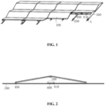
FIG. 1 is a schematic structural diagram of a photovoltaic assembly support system according to an embodiment of the present application; -
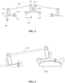
FIG. 2 is a schematic structural diagram of a photovoltaic assembly support system according to an embodiment of the present application in another view angle; -
FIG. 3 is a schematic structural diagram of a character ""-shaped photovoltaic assembly bodies according to an embodiment of the present application;
-
FIG. 4 is a schematic structural diagram of a character "-"-shaped photovoltaic assembly body according to an embodiment of the present application; -
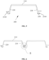
FIG. 5 is a schematic structural diagram of a support body according to an embodiment of the present application; -
FIG. 6 is a schematic structural diagram of two support bodies in connection with each other according to an embodiment of the present application; -
FIG. 7 is a partially enlarged view of B ofFIG. 6 ; -
FIG. 8 is another schematic structural diagram of a support body according to an embodiment of the present application; -
FIG. 9 is a partially enlarged view of A ofFIG. 1 ; and -
FIG. 10 is a schematic structural diagram of an upper connecting member according to an embodiment of the present application. -
- 100
- photovoltaic assembly body
- 110
- upper frame
- 120
- lower frame
- 200
- support body
- 210
- first connecting portion
- 220
- second connecting portion
- 2210
- first barb structure
- 230
- third connecting portion
- 2310
- second barb structure
- 250
- buffer adhesive tape
- 260
- broken line-shaped hole
- 300
- upper connecting member
- 310
- first position-limiting groove
- 320
- second position-limiting groove
- 330
- upper position-limiting portion
- 400
- lower connecting member
- 410
- third position-limiting groove
- 420
- engaging hook
- 430
- lower position-limiting portion
- 440
- first through hole
- 450
- opening
- 500
- side baffle plate
- 600
- supporting member
- 700
- second fixing member
- 710
- gasket
- 800
- counterweight block
- 810
- counterweight groove
- In the description of the present application, unless otherwise expressly specified and limited, the term "connected to each other", "connected", or "fixed" is to be construed in a broad sense, for example, as securely connected, detachably connected, or integrated; mechanically connected or electrically connected; directly connected to each other, indirectly connected to each other via an intermediary, internal connection between two components, or interaction between two components. For those of ordinary skill in the art, specific meanings of the preceding terms in the present application may be understood based on specific situations.
- In the present application, unless otherwise expressly specified and limited, a first feature being "on" or "under" a second feature may include the first feature and the second feature being in direct contact, or may include the first feature and the second feature not being in direct contact but being in contact with each other through an additional feature therebetween. Moreover, the first feature being "on", "above" or "over" the second feature includes the first feature being directly on, above or over and obliquely on, above or over the second feature, or simply indicates that the first feature is at a higher level than the second feature. The first feature being "under", "below" or "underneath" the second feature includes the first feature being directly under, below or underneath and obliquely under, below or underneath the second feature, or simply represents that the first feature is at a lower level than the second feature.
- In the description of this embodiment, the orientational or positional relationships indicated by terms "above", "below", "left", "right", and the like are based on the orientational or positional relationships shown in the drawings, and are merely for ease of description and simplifying an operation, rather than indicating or implying that the referred device or element must have a specific orientation and be constructed and operated in a specific orientation. Moreover, the terms "first" and "second" are used only to distinguish between descriptions and have no special meaning.
- As shown in
FIG. 1 to FIG. 4 , a photovoltaic assembly support system is provided according to this embodiment, for supporting aphotovoltaic assembly body 100. The photovoltaic assembly support system mainly includes asupport body 200, a lower connectingmember 400 and an upper connectingmember 300. Multiple lower connectingmembers 400 are provided, and the multiple lower connectingmembers 400 are arranged on thesupport body 200. The upper connectingmember 300 includes a first position-limitinggroove 310 and a second position-limitinggroove 320, and the first position-limitinggroove 310 and the lower connectingmembers 400 are arranged to enable thephotovoltaic assembly body 100 to be clamped between the first position-limitinggroove 310 and the lower connectingmembers 400, and/or the second position-limitinggroove 320 and the lower connectingmembers 400 are arranged to enable thephotovoltaic assembly body 100 to be clamped between the second position-limitinggroove 320 and the lower connectingmembers 400. For example, in a case wherephotovoltaic assembly bodies 100 are required to be arranged in rows of odd number, the operator may clamp thephotovoltaic assembly bodies 100 between the first position-limitinggrooves 310 and the lower connectingmembers 400, or clamp thephotovoltaic assembly bodies 100 between the second position-limitinggrooves 320 and the lower connectingmembers 400, so that each row ofphotovoltaic assembly bodies 100 forms a character "-"-shaped structure. In a case wherephotovoltaic assembly bodies 100 need to be arranged in rows of even number, the operator may clamp columns of the even number ofphotovoltaic assembly bodies 100 between the first position-limitinggrooves 310 and the lower connectingmembers 400 and between the second position-limitinggrooves 320 and the lower connectingmembers 400, respectively, so that each two rows ofphotovoltaic assembly bodies 100 form a character "A" -shaped structure, thereby improving the flexibility and applicability of the photovoltaic assembly support system. - Exemplarily,
multiple support bodies 200, multiple lower connectingmembers 400, and multiple upper connectingmembers 300 in this embodiment may be provided, and the operator may adjust distances between themultiple support bodies 200 according to practical requirements, thereby improving the stability and reliability of thephotovoltaic assembly bodies 100, so that thephotovoltaic assembly bodies 100 are not apt to be severely deformed when subjected to a large mechanical load. In an embodiment, a distance between thesupport body 200 and a short side of thephotovoltaic assembly body 100 ranges from one fourth to one fifth of a long side of thephotovoltaic assembly body 100. It is worth noting that at two ends of a column ofphotovoltaic assembly bodies 100, twosupport bodies 200 are flush with the short sides of thephotovoltaic assembly bodies 100, in this way, thephotovoltaic assembly bodies 100 are prevented from injuring the operator due to protruding from thesupport body 200, and moreover, the aesthetics of the whole photovoltaic assembly system can be improved. - As shown in
FIG. 4 , in the case where the operator needs to arrange thephotovoltaic assembly bodies 100 into the character "-"-shaped structure, since a level at which each upper connectingmember 300 is located is higher than a lever at which the lower connectingmembers 400 are located, it is simply required to add one supportingmember 600 for supporting the upper connectingmember 300 below each upper connectingmember 300, thereby achieving the installation of the character "-"-shaped structure of thephotovoltaic assembly bodies 100, and further improving the stability and reliability of the photovoltaic assembly support system. - It should be noted that, as shown in
FIG. 3 and FIG. 4 , thephotovoltaic assembly body 100 in this embodiment includes a photovoltaic assembly panel, anupper frame 110 and alower frame 120. The photovoltaic assembly panel is embedded between theupper frame 110 and thelower frame 120, and theupper frame 110 is arranged to be engaged by the upper connectingmember 300, and thelower frame 120 is arranged to be engaged by the lower connectingmembers 400, thereby achieving the stable connection between thephotovoltaic assembly body 100 and the photovoltaic assembly support system. - Optionally, the
support body 200, the lower connectingmembers 400 and the upper connectingmember 300 in this embodiment are made of an aluminum alloy material that is light in weight and has a certain rigidity. Apparently, in other embodiments of the present application, the operator may also select other materials for processing, such as engineering plastics, copper alloys, and stainless steels. - Compared with the related art, the photovoltaic assembly support system provided in this embodiment has a simple structure, and does not need to use an additional supporting component such as an upright post, and the supporting to the
photovoltaic assembly body 100 may be achieved simply through the cooperation of the upper connectingmember 300, the lower connectingmembers 400 and thesupport body 200, thereby saving the manufacturing cost and improving the working efficiency of manufacturing and installing the photovoltaic assembly support system. Moreover, thesupport body 200 is not affected by the supporting component such as an upright post, and the distance between thesupport bodies 200 may be adjusted according to the practical carrying capacity of thephotovoltaic assembly body 100, thereby improving the mechanical loading capacity of thephotovoltaic assembly body 100 and prolonging the service life. - As shown in
FIG. 5 , in this embodiment, thesupport body 200 includes a first connectingportion 210, a second connectingportion 220 and a third connectingportion 230. The second connectingportion 220 is formed by extending from a first end of the first connectingportion 210, and the third connectingportion 230 is formed by extending from a second end of the first connectingportion 210, that is, the first connectingportion 210, the second connectingportion 220 and the third connectingportion 230 are integrally formed. - The second connecting
portion 220 and the third connectingportion 230 are arranged in a shape of character "A", in this way, the stability of thesupport body 200 can be improved, and thephotovoltaic assembly body 100 is prevented from being wobbled. - In an embodiment, as shown in
FIG. 6 andFIG. 7 , an end of the second connectingportion 220 facing away from the first connectingportion 210 is provided with afirst barb structure 2210, and an end of the third connectingportion 230 facing away from the first connectingportion 210 is provided with asecond barb structure 2310, and thefirst barb structure 2210 may be engaged and fitted with thesecond barb structure 2310. In this way, twosupport bodies 200 may be engaged by thefirst barb structure 2210 and thesecond barb structure 2310, and further thesupport bodies 200 may be widened, so that the photovoltaic assembly support system can carry thephotovoltaic assembly bodies 100 of different sizes, that is, the operator can more flexibly match thesupport bodies 200 in the application environment, thereby avoiding insufficient or excessive loading capacity of thesupport bodies 200. - As shown in
FIG. 6 andFIG. 7 , in this embodiment, thefirst barb structure 2210 and thesecond barb structure 2310 are designed in a form of "single straight buckle", and further, thefirst barb structure 2210 and thesecond barb structure 2310 are engaged so as to achieve the stable connection of twoadjacent support bodies 200. In other embodiments of the present application, the operator can design, according to practical requirements, thefirst barb structure 2210 and thesecond barb structure 2310 as other forms such as "single oblique buckle", "multiple straight buckles" and "spin buckle". - In an embodiment, as shown in
FIG. 5 , at each of the end of the second connectingportion 220 facing away from the first connectingportion 210 and the end of the third connectingportion 230 facing away from the first connectingportion 210, a bufferadhesive tape 250 is provided, the bufferadhesive tape 250 can reduce the rigidity of contact of thesupport body 200 with an application environment such as a floor or a roof plane, thereby prolonging the service life of thesupport body 200. Optionally, the bufferadhesive tape 250 is made of a silica gel material. - As shown in
FIG. 8 , thesupport bodies 200 may be connected in a vertical stacking combination manner. In a practical application, since the length of asingle support body 200 is limited, a situation often occurs that the length of onesupport body 200 is not sufficient and thus it is required to splice thesupport bodies 200. In the related art, it is generally necessary to splice and fix twosupport bodies 200 along a length direction of thesupport bodies 200 by snap-fit members or a fastener. The structure of thesupport body 200 in this embodiment is large at the bottom and small at the top, i.e., a positive trapezoidal structure, in this way, thesupport bodies 200 can be spliced and simply need to be fixed. This stacking manner of thesupport bodies 200 may also be applied to a practical situation that there are fluctuating planes at different levels on the plane of the installation environment, thereby improving the flexible applicability and versatility of thesupport body 200 and the universality of the photovoltaic assembly support system. - As shown in
FIG. 3, FIG. 4 andFIG. 10 , in this embodiment, each of the lower connectingmembers 400 includes a third position-limitinggroove 410, and the third position-limitinggroove 410 is configured to engage thephotovoltaic assembly body 100. In an embodiment, the upper connectingmember 300 and the lower connectingmembers 400 are each provided with anengaging hook 420, and theengaging hook 420 is configured to engage thephotovoltaic assembly body 100. That is, in this embodiment, an end of the first position-limitinggroove 310, an end of the second position-limitinggroove 320, and an end of the third position-limitinggroove 410 are each extended outward to form theengaging hook 420, and the engaginghooks 420 may engage theupper frame 110 and thelower frame 120 of thephotovoltaic assembly bodies 100, this engagement is an interference fit, thereby improving the stability and reliability of the connection between thephotovoltaic assembly body 100 and the photovoltaic assembly support system. - In an embodiment, with continued reference to
FIG. 3, FIG. 4 andFIG. 10 , the lower connectingmember 400 includes a lower position-limitingportion 430, and the upper connectingmember 300 includes an upper position-limitingportion 330, the upper position-limitingportion 330 and the lower position-limitingportion 430 each abut against a side wall of thephotovoltaic assembly body 100, so that the upper position-limitingportion 330 and the lower position-limitingportion 430 can have a certain limiting effect on thephotovoltaic assembly body 100, that is, can limit the displacement of thephotovoltaic assembly body 100, prevent thephotovoltaic assembly body 100 from being separated from the photovoltaic assembly support system, thereby improving the stability and reliability of thephotovoltaic assembly body 100. - As shown in
FIG. 1 , in this embodiment, the photovoltaic assembly support system includes aside baffle plate 500 and first fixing members, the upper connectingmember 300 and each of the lower connectingmembers 400 are each provided with a first throughhole 440, theside baffle plate 500 is provided with second through holes, and each of the first fixing members is arranged to partially pass through one of the second through holes to be connected to a respect one of the first throughholes 440 of the upper connectingmember 300 and the lower connectingmembers 400. - Exemplarily, the first fixing member may be selected from parts such as a bolt, a screw, a threaded rod and a rivet. The stable connection of the
side baffle plate 500 to the upper connectingmember 300 and the lower connectingmember 400 is achieved by the first fixing members, so that theside baffle plate 500, thephotovoltaic assembly body 100, the floor or the roof plane may be arranged to define a relatively closed space, whereby litters or foreign matters can be prevented from entering the underside of thephotovoltaic assembly body 100, and furthermore, thephotovoltaic assembly body 100 can be prevented from being subjected to the wind pressure from bottom to top along the lower surface to the upper surface of thephotovoltaic assembly body 100, thereby preventing thephotovoltaic assembly body 100 from being wobbled during use, and further, improving the stability of thephotovoltaic assembly body 100 and the photovoltaic assembly support system. - In order to save the cost and reduce the weight of the photovoltaic assembly system, in this embodiment, the
side baffle plate 500 is arranged only at the photovoltaic assembly panel at an edge position of the whole photovoltaic system. The photovoltaic assembly panels at a middle position does not need to be connected by theside baffle plate 500, so that the upper connectingmembers 300 and the lower connectingmembers 400 at the middle position may have their positions flexibly and freely adjusted according to the stress conditions of the photovoltaic assembly panels, thereby improving the working efficiency of assembling the upper connectingmembers 300 and the lower connectingmembers 400. - As shown in
FIG. 1 , in this embodiment, the photovoltaic assembly support system further includes acounterweight block 800 and acounterweight groove 810. Thecounterweight block 800 is placed in thecounterweight groove 810, and thecounterweight groove 810 is arranged in thesupport body 200, which enables the counterweight block 800 to improve the weight and stability of the photovoltaic assembly support system, thereby avoiding the risk of displacement or release of the photovoltaic assembly support system in a severe weather such as a strong wind. The number of counterweight blocks 800 and positions of the counterweight blocks 800 may be flexibly set by the operator according to practical conditions, for example, the number of counterweight blocks 800 may be one, three, five, and the like, and the counterweight blocks 800 may be arranged in thecounterweight groove 810 at equal intervals, or may be arranged in thecounterweight groove 810 at unequal intervals. - Apparently, according to the practical installation environment of the
photovoltaic assembly body 100, thesupport body 200 may be removed by the operator and replaced with multiple discrete cement pier structures by the operator, and then thephotovoltaic assembly body 100 is fixed on the cement pier structures. Such structure maximizes the effect of the cement pier structures, that is, the cement pier structures not only have the function of thecounterweight block 800, i.e., increasing the weight and stability of the photovoltaic assembly support system, but also may function to support thephotovoltaic assembly body 100, thereby saving the cost, reducing the installation process, and improving the installation efficiency. - As shown in
FIG. 1 andFIG. 9 , in this embodiment, the photovoltaic assembly support system includes asecond fixing member 700, and the second fixingmember 700 is arranged to connect one of the lower connectingmembers 400 to thesupport body 200. Thesecond fixing member 700 may be selected from parts such as a bolt, a screw, a threaded rod and a rivet, and the second fixingmember 700 may be configured in a structure such as a round table, and a square table. Thesupport body 200 is provided with a broken line-shapedhole 260, the lower connectingmember 400 is provided with anopening 450, and the second fixingmember 700 is arranged to partially pass through theopening 450 and the broken line-shapedhole 260 to connect the lower connectingmember 400 to thesupport body 200. When to mount the lower connectingmember 400, the lower connectingmember 400 is firstly placed on thesupport body 200, and the second fixingmember 700 to be mounted is partially passed through the broken line-shapedhole 260 and is located at the end of the broken line-shapedhole 260, and in this case, the second fixingmember 700 is facing away from the photovoltaic assembly panel. That is, in this case, the lower connectingmember 400 is movable freely on thesupport body 200, and then assembling steps such as position adjustment and cable laying out are conveniently performed. After the cable laying out is completed, the second fixingmember 700 is slid into theopening 450 of the lower connectingmember 400 along the broken line-shapedhole 260, and then the lower connectingmember 400 and thesupport body 200 can be stably connected to each other by tightening the second fixingmember 700. Moreover, an electrically conductive cable is arranged to pass through the broken line-shapedhole 260, so that the static electricity in the photovoltaic assembly panel may be led out to the earth in time, and furthermore, the danger of electric shock of the operator can be avoided, and the lightning protection effect can also be achieved in a thunderstorm weather. - In an embodiment, a
gasket 710 is disposed on the second fixingmember 700, and thegasket 710 is sleeved on the second fixingmember 700. Thegasket 710 is made of a flexible material such as silica gel, and thegasket 710 can reduce the rigidity of contact between thesupport body 200 and the lower connectingmember 400, and further, better protect the photovoltaic assembly support system, and prolong the service life. - It should be noted that in the description of this specification, the terms "some embodiments" and "other embodiments" herein mean that specific features, specific structures, specific materials, or specific characteristics described in connection with an embodiment or example are included in at least one embodiment or example of the present application. In this description, illustrative expressions of these terms do not necessarily refer to the same embodiment or example. Moreover, the specific features, the specific structures, the specific materials, or the specific characteristics described may be combined in any one or more embodiments or examples in any suitable manner.
Claims (10)
- A photovoltaic assembly support system, configured to support a photovoltaic assembly body (100) and comprising:a support body (200);a plurality of lower connecting members (400), wherein the plurality of lower connecting members (400) are arranged on the support body (200); andan upper connecting member (300), wherein the upper connecting member (300) comprises a first position-limiting groove (310) and a second position-limiting groove (320), the first position-limiting groove (310) and the plurality of lower connecting members (400) are arranged to enable the photovoltaic assembly body (100) to be clamped between the first position-limiting groove (310) and the plurality of lower connecting members (400); and/or the second position-limiting groove (320) and the plurality of lower connecting members (400) are arranged to enable the photovoltaic assembly body (100) to be clamped between the second position-limiting groove (320) and the plurality of lower connecting members (400).
- The photovoltaic assembly support system of claim 1, wherein the support body (200) comprises a first connecting portion (210), a second connecting portion (220) and a third connecting portion (230), the second connecting portion (220) is formed by extending from a first end of the first connecting portion (210), the third connecting portion (230) is formed by extending from a second end of the first connecting portion (210), and the second connecting portion (220) and the third connecting portion (230) are arranged in a shape of character "A".
- The photovoltaic assembly support system of claim 2, wherein an end of the second connecting portion (220) facing away from the first connecting portion (210) is provided with a first barb structure (2210), an end of the third connecting portion (230) facing away from the first connecting portion (210) is provided with a second barb structure (2310), and the first barb structure (2210) is fitted with the second barb structure (2310).
- The photovoltaic assembly support system of claim 3, wherein a buffer adhesive tape (250) is provided at each of the end of the second connecting portion (220) facing away from the first connecting portion (210) and the end of the third connecting portion (230) facing away from the first connecting portion (210).
- The photovoltaic assembly support system of claim 1, wherein each of the plurality of lower connecting members (400) comprises a third position-limiting groove (410), and the third position-limiting groove (410) is configured to engage the photovoltaic assembly body (100).
- The photovoltaic assembly support system of claim 5, wherein an end of the first position-limiting groove (310), an end of the second position-limiting groove (320) and an end of the third position-limiting groove (410) are each extended to form an engaging hook (420), and the engaging hook (420) is configured to engage the photovoltaic assembly body (100).
- The photovoltaic assembly support system of claim 6, wherein each of the plurality of lower connecting members (400) comprises a lower position-limiting portion (430), the upper connecting member (300) comprises an upper position-limiting portion (330), and the upper position-limiting portion (330) and the lower position-limiting portion (430) each abut against a side wall of the photovoltaic assembly body (100).
- The photovoltaic assembly support system of claim 1, comprising a side baffle plate (500) and first fixing members, wherein the upper connecting member (300) and each of the plurality of lower connecting members (400) are each provided with a first through hole (440), the side baffle plate (500) is provided with second through holes, and each of the first fixing members is arranged to partially pass through one of the second through holes to be connected to a respective one of first through holes (440) of the upper connecting member (300) and the plurality of lower connecting members (400).
- The photovoltaic assembly support system of claim 1, comprising a second fixing member (700), wherein the second fixing member (700) is configured to connect a lower connecting member (400) of the plurality of lower connecting members (400) to the support body (200).
- The photovoltaic assembly support system of claim 9, wherein the support body (200) is provided with a broken line-shaped hole (260), each of the plurality of lower connecting members (400) is provided with an opening (450), and the second fixing member (700) is arranged to partially pass through the opening (450) and the broken line-shaped hole (260) to connect the lower connecting member (400) to the support body (200).
Applications Claiming Priority (2)
| Application Number | Priority Date | Filing Date | Title |
|---|---|---|---|
| CN202210312948.5A CN114584055A (en) | 2022-03-28 | 2022-03-28 | Photovoltaic module's mounting system |
| PCT/CN2023/084135 WO2023185751A1 (en) | 2022-03-28 | 2023-03-27 | Bracket system for photovoltaic module |
Publications (1)
| Publication Number | Publication Date |
|---|---|
| EP4277119A1 true EP4277119A1 (en) | 2023-11-15 |
Family
ID=81777014
Family Applications (1)
| Application Number | Title | Priority Date | Filing Date |
|---|---|---|---|
| EP23722805.1A Pending EP4277119A1 (en) | 2022-03-28 | 2023-03-27 | Bracket system for photovoltaic module |
Country Status (3)
| Country | Link |
|---|---|
| EP (1) | EP4277119A1 (en) |
| CN (1) | CN114584055A (en) |
| WO (1) | WO2023185751A1 (en) |
Families Citing this family (1)
| Publication number | Priority date | Publication date | Assignee | Title |
|---|---|---|---|---|
| CN114584055A (en) * | 2022-03-28 | 2022-06-03 | 横店集团东磁股份有限公司 | Photovoltaic module's mounting system |
Family Cites Families (10)
| Publication number | Priority date | Publication date | Assignee | Title |
|---|---|---|---|---|
| JP2002180609A (en) * | 2000-12-13 | 2002-06-26 | Kawasaki Steel Corp | Solar battery panel array mounted on folded plate roof and its mounting structure |
| DE202008000528U1 (en) * | 2008-01-11 | 2008-03-20 | Metzger, Herbert H. W. | Solar array |
| DE202011001411U1 (en) * | 2011-01-12 | 2011-03-17 | Fischer Lichtsysteme Gmbh | Mounting system for a solar system and solar system with the mounting system |
| US10302333B2 (en) * | 2011-09-30 | 2019-05-28 | Sunrun South Llc | Wind tunnel optimized solar panel system |
| EP3097369A1 (en) * | 2014-01-24 | 2016-11-30 | Renusol GmbH | Stand unit for stabilizing solar panels on a flat roof |
| JP2016187263A (en) * | 2015-03-27 | 2016-10-27 | パナソニックIpマネジメント株式会社 | Solar battery module and photovoltaic power generation device |
| CN214658297U (en) * | 2021-01-20 | 2021-11-09 | 宣城睿晖宣晟企业管理中心合伙企业(有限合伙) | Mounting structure, photovoltaic system |
| CN114050782A (en) * | 2021-11-16 | 2022-02-15 | 横店集团东磁股份有限公司 | Integral type photovoltaic module |
| CN217216422U (en) * | 2022-03-28 | 2022-08-16 | 江苏东磁新能源科技有限公司 | Photovoltaic support system |
| CN114584055A (en) * | 2022-03-28 | 2022-06-03 | 横店集团东磁股份有限公司 | Photovoltaic module's mounting system |
-
2022
- 2022-03-28 CN CN202210312948.5A patent/CN114584055A/en active Pending
-
2023
- 2023-03-27 EP EP23722805.1A patent/EP4277119A1/en active Pending
- 2023-03-27 WO PCT/CN2023/084135 patent/WO2023185751A1/en unknown
Also Published As
| Publication number | Publication date |
|---|---|
| CN114584055A (en) | 2022-06-03 |
| WO2023185751A1 (en) | 2023-10-05 |
Similar Documents
| Publication | Publication Date | Title |
|---|---|---|
| US10365017B2 (en) | Self-adjusting end clamp | |
| US8418983B2 (en) | Slider clip and photovoltaic structure mounting system | |
| CN101426988B (en) | Mounting system for a solar panel | |
| EP3114416B1 (en) | Deflector element and system with for mounting one or more solar panel modules | |
| JP4637231B2 (en) | Solar cell module installation stand | |
| US9188365B2 (en) | Frame for supporting solar module | |
| EP4277119A1 (en) | Bracket system for photovoltaic module | |
| US10355636B2 (en) | Structure and support device for photovoltaic arrays | |
| JP2010027979A (en) | Solar photovoltaic system, and method of manufacturing the same | |
| US20160109054A1 (en) | Panel support structure | |
| JP5891109B2 (en) | Solar cell module fixing structure and solar cell module fixing method | |
| JP2015227558A (en) | Photovoltaic power generator | |
| KR102258755B1 (en) | Support Structure for Solar Cell Module | |
| US20120216465A1 (en) | Fastener free assembly system for solar panel arrays | |
| JP2004063932A (en) | Fixing apparatus and sunlight utilizing apparatus using it | |
| CN203537301U (en) | Solar equipment installing system on flat roof | |
| CN219509016U (en) | Photovoltaic module installation device and building photovoltaic integrated system | |
| CN103607167A (en) | Solar energy equipment installation system on flat roof | |
| CN211557194U (en) | Photovoltaic support and photovoltaic module structure of arranging | |
| CN220107915U (en) | Photovoltaic frame and photovoltaic module | |
| CN217849286U (en) | Photovoltaic module fixed knot constructs and photovoltaic system | |
| KR19990023401U (en) | Solar Module Fixture | |
| KR101654086B1 (en) | A solar panel supporting structure for roof panels | |
| CN116404956A (en) | Photovoltaic panel support of flexible photovoltaic support system and mounting structure thereof | |
| JP5831429B2 (en) | Solar cell module fixture and solar power generation system using the fixture |
Legal Events
| Date | Code | Title | Description |
|---|---|---|---|
| STAA | Information on the status of an ep patent application or granted ep patent |
Free format text: STATUS: UNKNOWN |
|
| STAA | Information on the status of an ep patent application or granted ep patent |
Free format text: STATUS: THE INTERNATIONAL PUBLICATION HAS BEEN MADE |
|
| PUAI | Public reference made under article 153(3) epc to a published international application that has entered the european phase |
Free format text: ORIGINAL CODE: 0009012 |
|
| STAA | Information on the status of an ep patent application or granted ep patent |
Free format text: STATUS: REQUEST FOR EXAMINATION WAS MADE |
|
| 17P | Request for examination filed |
Effective date: 20230518 |
|
| AK | Designated contracting states |
Kind code of ref document: A1 Designated state(s): AL AT BE BG CH CY CZ DE DK EE ES FI FR GB GR HR HU IE IS IT LI LT LU LV MC ME MK MT NL NO PL PT RO RS SE SI SK SM TR |