EP4273355A1 - Clutch actuator for a door lock - Google Patents
Clutch actuator for a door lock Download PDFInfo
- Publication number
- EP4273355A1 EP4273355A1 EP22171351.4A EP22171351A EP4273355A1 EP 4273355 A1 EP4273355 A1 EP 4273355A1 EP 22171351 A EP22171351 A EP 22171351A EP 4273355 A1 EP4273355 A1 EP 4273355A1
- Authority
- EP
- European Patent Office
- Prior art keywords
- shaft
- coupling member
- interlocking protrusion
- clutch actuator
- spring
- Prior art date
- Legal status (The legal status is an assumption and is not a legal conclusion. Google has not performed a legal analysis and makes no representation as to the accuracy of the status listed.)
- Pending
Links
- 230000008878 coupling Effects 0.000 claims abstract description 142
- 238000010168 coupling process Methods 0.000 claims abstract description 142
- 238000005859 coupling reaction Methods 0.000 claims abstract description 142
- 239000011800 void material Substances 0.000 claims abstract description 8
- 238000004804 winding Methods 0.000 claims abstract description 4
- 238000000034 method Methods 0.000 claims description 8
- 230000005540 biological transmission Effects 0.000 claims description 7
- 230000000903 blocking effect Effects 0.000 description 5
- 230000007246 mechanism Effects 0.000 description 4
- 230000003993 interaction Effects 0.000 description 3
- 230000010355 oscillation Effects 0.000 description 2
- 230000000295 complement effect Effects 0.000 description 1
- 230000001419 dependent effect Effects 0.000 description 1
- 230000001939 inductive effect Effects 0.000 description 1
- 238000004519 manufacturing process Methods 0.000 description 1
- 230000002093 peripheral effect Effects 0.000 description 1
- 230000036316 preload Effects 0.000 description 1
- 230000002123 temporal effect Effects 0.000 description 1
Images


Classifications
-
- E—FIXED CONSTRUCTIONS
- E05—LOCKS; KEYS; WINDOW OR DOOR FITTINGS; SAFES
- E05B—LOCKS; ACCESSORIES THEREFOR; HANDCUFFS
- E05B47/00—Operating or controlling locks or other fastening devices by electric or magnetic means
- E05B47/06—Controlling mechanically-operated bolts by electro-magnetically-operated detents
- E05B47/0676—Controlling mechanically-operated bolts by electro-magnetically-operated detents by disconnecting the handle
- E05B47/068—Controlling mechanically-operated bolts by electro-magnetically-operated detents by disconnecting the handle axially, i.e. with an axially disengaging coupling element
-
- E—FIXED CONSTRUCTIONS
- E05—LOCKS; KEYS; WINDOW OR DOOR FITTINGS; SAFES
- E05B—LOCKS; ACCESSORIES THEREFOR; HANDCUFFS
- E05B17/00—Accessories in connection with locks
- E05B17/20—Means independent of the locking mechanism for preventing unauthorised opening, e.g. for securing the bolt in the fastening position
- E05B17/2084—Means to prevent forced opening by attack, tampering or jimmying
-
- E—FIXED CONSTRUCTIONS
- E05—LOCKS; KEYS; WINDOW OR DOOR FITTINGS; SAFES
- E05B—LOCKS; ACCESSORIES THEREFOR; HANDCUFFS
- E05B15/00—Other details of locks; Parts for engagement by bolts of fastening devices
- E05B15/04—Spring arrangements in locks
- E05B2015/0403—Wound springs
- E05B2015/0406—Wound springs wound in a cylindrical shape
- E05B2015/0413—Wound springs wound in a cylindrical shape loaded by compression
-
- E—FIXED CONSTRUCTIONS
- E05—LOCKS; KEYS; WINDOW OR DOOR FITTINGS; SAFES
- E05B—LOCKS; ACCESSORIES THEREFOR; HANDCUFFS
- E05B47/00—Operating or controlling locks or other fastening devices by electric or magnetic means
- E05B47/0001—Operating or controlling locks or other fastening devices by electric or magnetic means with electric actuators; Constructional features thereof
- E05B2047/0014—Constructional features of actuators or power transmissions therefor
- E05B2047/0018—Details of actuator transmissions
- E05B2047/0026—Clutches, couplings or braking arrangements
- E05B2047/0031—Clutches, couplings or braking arrangements of the elastic type
-
- E—FIXED CONSTRUCTIONS
- E05—LOCKS; KEYS; WINDOW OR DOOR FITTINGS; SAFES
- E05B—LOCKS; ACCESSORIES THEREFOR; HANDCUFFS
- E05B47/00—Operating or controlling locks or other fastening devices by electric or magnetic means
- E05B47/0001—Operating or controlling locks or other fastening devices by electric or magnetic means with electric actuators; Constructional features thereof
- E05B47/0012—Operating or controlling locks or other fastening devices by electric or magnetic means with electric actuators; Constructional features thereof with rotary electromotors
Definitions
- the invention relates to a clutch actuator for a door lock.
- the clutch actuator may comprise a shaft with a longitudinal axis and an azimuthal bearing surface, wherein the azimuthal bearing surface may provide a block against a rotation in an azimuthal direction and may extend in at least one other direction.
- the clutch actuator may further comprise a coupling member, being movably supported relative to the shaft by the azimuthal bearing surface between an open position and a closed position.
- the coupling member may have at least a first spring block and a second spring block, The first spring block and the second spring blocks may face in mutually opposite directions, wherein said mutual opposite directions may be parallel or anti-parallel to a third direction.
- a helical spring may be movably supported to enable a movement parallel to the third direction, wherein the movement of the helical spring parallel to the third direction may be limited in the third direction by the first spring block and in the opposite direction by the second spring block.
- the helical spring may have multiple turns.
- a spindle may be torque proof connected to a motor shaft and rotatably supported, wherein a protrusion of the spindle may engage in a void between two adjacent turns of the helical spring.
- Corresponding locking systems comprise at least one user device with an electronic identification for authentication of a user.
- the electronic identification is transmitted from the user device to the lock and if the key is considered valid by the lock, the lock changes its state from unlocked to locked or from locked to unlocked.
- the electronic identification takes the function of a mechanical key in a purely mechanical locking system.
- RFID-transponders as user devices.
- EP 1 710 753 A2 WO 03/071060 A1 , EP 2 195 767 A1 , EP 1 787 241 B1 to name only a few).
- keypads, fingerprint scanners, iris scanners or any other human machine interface may be used to enter a code that functions as a key to the electronic lock.
- a lock When a lock changes its state from “locked” to "unlocked” a user gains access to a building, a room, a cabinet or a drawer or something else.
- One possibility to provide the access is to enable a user to operate a latch and/or a dead bolt (jointly "latch” hereinafter, unless explicitly stated). This can either be done by unblocking the latch, i.e. by releasing a coupling between the latch and a door leaf and/or a door frame.
- the latch may be coupled to a handle. In both cases a selective coupling needs to be opened and closed.
- Such selective couplings are as well referred to as clutches and are known from a number of publications, e.g.
- All these clutches have a clutch actuator mechanism.
- These clutch actuator mechanisms are reliable in that the motor for moving the coupling member from the closed position to the open position can be actuated without checking if the coupling member is blocked or jammed and in that the coupling member is moved in the corresponding position once the blockage or jamming is resolved due to an elastic connection between the motor's drive shaft and the coupling member being provided by the spring.
- the spring temporally decouples a movement of the coupling member from an actuation of the motor.
- the object underlying the invention is to improve safety of a door lock with a clutch for coupling a handle shaft with a locking member shaft.
- the clutch actuator according to the invention may be used to open and close a clutch for selectively coupling two preferably aligned shafts of a door lock mechanism.
- the clutch actuator may be integrated into at least one of the two shafts may be hence comprise a (first) shaft of these two shafts.
- the first shaft (hereinafter “the shaft”) has a longitudinal axis.
- the longitudinal axis may be the rotational axis of the shaft.
- the longitudinal axis implicitly defines an azimuthal direction (herein as well “the first direction”).
- the shaft may further comprise a first azimuthal bearing surface, wherein the first azimuthal bearing surface provides a first block against a rotation in the azimuthal direction and extends in at least one other direction. This other direction will be referred to as well as second direction. Only to avoid misunderstandings, the first and the second direction are linearly independent.
- the first block can thus be considered as an abutment blocking a rotation in the azimuthal direction, while allowing for a movement along the surface of the block in the second direction.
- the azimuthal abutment i.e. the azimuthal bearing surface, may thus limit a rotation of a coupling member in the azimuthal direction, while allowing for a translation and/or a rotation and/or pivotal movement in at least the second direction (and of course opposite to the second direction).
- a torque can be transferred by the coupling member in the azimuthal direction into the shaft and the coupling member can be moved, e.g. shifted, relative to the shaft from an open position and/or orientation (jointly "open position” ) into a closed position and/or orientation (jointly "closed position”).
- the coupling member is preferably movably supported at least inter alia by the bearing surface between the open position and the closed position.
- the coupling member preferably has a second azimuthal bearing surface, wherein the second azimuthal bearing surface provides a second block against a rotation in a direction opposite to the first direction.
- the azimuthal direction is clockwise
- the opposite direction is counter clockwise and vice versa.
- the second block may face towards the first block and may extend as well at least in the second direction.
- the movable support of the coupling member relative to the shaft hence allows to extend at least a portion of the coupling member into a recess of a second shaft of the clutch, thereby providing a positive locking of the first shaft and the second shaft in an azimuthal direction via the coupling member.
- the coupling member may alternatively or in addition be extended in its closed position over at least a portion of the second shaft to provide a positive locking.
- a recess of the coupling member may be shifted over at least a portion of the second shaft.
- a positive locking can be obtained, typically if the recess and the corresponding portion of the second shaft or the coupling member, respectively are not continuously rotationally invariant, i.e. if they have broken rotational symmetries with respect to the longitudinal axis.
- the coupling may as well be provided by a releasable friction connection often as well referred to as force fit.
- force fit is an alternative, at least one of the coupling member and the corresponding portion of the second shaft can be continuously rotationally invariant.
- the movable support allows as well to retract the coupling member into its open position. In the open position, the positive locking and/or the force fit of the coupling member with the second shaft is released. In the open position, the torque proof connection provided by the azimuthal block of the first shaft may be released.
- the coupling member may have at least a first spring block and a second spring block.
- the first spring block and the second spring block may preferably face in mutually opposite directions. These mutual opposite directions are preferably parallel to a third direction.
- the third direction and the second direction may preferably be parallel or anti-parallel to each other. This (anti) parallelism is a preferred example as it simplifies the clutch actuator, but it is not required.
- a helical spring may be movably supported to enable a movement parallel to the third direction, wherein the movement parallel to the third direction is limited in the third direction by the first spring block and in the opposite direction by the second spring block.
- the helical spring may have multiple turns.
- a spindle may be torque proof connected to a motor shaft and rotatably supported, wherein a protrusion of the spindle may engage in a void between two adjacent turns of the helical spring.
- the protrusion of the spindle may form a recess into which the filament forming the helical spring engages.
- a movement in the open or in the closed direction of the coupling member may load a secondary spring.
- the secondary spring may push the coupling member back into the closed or open position, respectively (i.e. after the secondary spring has been loaded), respectively, if the force being applied by the helical spring is reduced by rotating the spindle in the corresponding direction.
- the surface of the coupling member against which the secondary spring pushes may be considered as the first or the second spring block and the secondary spring may be considered as a portion of the helical spring, regardless of the type of the secondary spring.
- the position of the coupling member is controlled by rotating the spindle.
- a rotation of the spindle shifts the position of the coupling member in which an equilibrium of the restoring forces of the at least one loaded spring is established (equilibrium position). If the coupling member is not blocked, it hence moves into this equilibrium position. If it is blocked it cannot move, but once the blocking is released, the coupling member will move in the direction into which it is preloaded.
- the spring(s) hence enable to decouple the point in time of controlling the drive which rotates the spindle and the point in time the coupling member moves as a result of the rotation of the spindle as the spring(s) store the work provided by the drive and provide it once blocking of the coupling member is released.
- the coupling member has a first interlocking protrusion.
- the optional first interlocking protrusion may extend towards the spindle.
- the spindle may have a second interlocking protrusion extending towards the coupling member.
- the movement of the first interlocking protrusion from the open position to the closed position hence defines a cylinder surface (for a definition of a cylinder surface, see Bronshtein, Semendayev, Musiol, Muehlig, Handbook of Mathematics, Springer, 5th ed., Sect. 3.3.4, ISBN 978-3-540-72121-5 ).
- the second interlocking protrusion intersects the path.
- the coupling member cannot be moved along the path unless at least one of the two interlocking protrusions is moved out of said path.
- the first interlocking protrusion and the second interlocking protrusion preferably have a radial overlap, wherein "radial" references to the spindle axis.
- Radial overlap means that the intersecting set of the extension of the first interlocking protrusion in the radial direction and set of the extension of the second interlocking protrusion is not empty.
- the spindle is rotated to drive the coupling member into the closed position.
- the second interlocking protrusion rotates relative to the coupling member and thus enables the first protrusion to pass the path.
- the first interlocking protrusion and the second interlocking protrusion preferably each have passage (first passage and second passage, respectively), wherein the first interlocking protrusion fits into or through the second passage and the second interlocking protrusion fits into or through the first passage, while the spindle is rotated relative to the coupling member to load the helical spring towards or against the second direction and to thereby move the coupling member from its open position into its closed position or from the closed position into the open position, respectively.
- the passages may be considered as recesses having an azimuthal extension allowing the corresponding other interlocking protrusion to pass the respective passage while the spindle is rotated and the coupling member moves towards its closed position.
- the first passages is thus between at least two surfaces that connect the two axially facing sides of the first interlocking protrusion and the second passage is in between of at least two surfaces that connect the two axially facing sides of the second interlocking protrusion, wherein axially references to the spindle axis.
- the spindle axis may be at least essentially aligned with the longitudinal shaft axis, such alignment is preferred but not required.
- the invention is, inter alia, based on the observation, that the elastic connection between the coupling member and the motor for driving the coupling member as well provides the risk, that the coupling member is shifted into its closed position by inducing an oscillation of the coupling member, e.g. by hammering against the door leaf, hitting the door lock or the like. This may in some cases allow a non-authorized person to bring the coupling member at least for short period of time into a position in which the coupling member engages with its counterpart (closed position). If in this moment the clutch is loaded by operating the handle, the coupling member is jammed by the load and the latch and/or the dead bolt can be retracted.
- the interaction of the first and the second interlocking protrusions protects against such un-authorized movement of the coupling member into the closed position. Unauthorized access to a door having a door lock with the claimed clutch actuator can be avoided. The safety of door locks can be enhanced by the clutch actuator.
- At least one of the first interlocking protrusion and the second interlocking protrusion is a helical structure aligned with the spindle axis or in other words at least one of the first interlocking protrusion and the second interlocking protrusion is and/or forms a screw thread being aligned with the spindle axis, while the respective other interlocking member is configured to temporarily engage and travel through the voids between turns of the helical structure while the spindle is rotated.
- the first interlocking member is a pin and the second interlocking protrusion is a helical structure.
- the first interlocking protrusion is a helical structure and the second interlocking protrusion is a pin.
- the first interlocking protrusion and the second interlocking protrusion are both helical structures.
- the void between the turns of at least one helical structure provides a helical passage for the respective other interlocking protrusion.
- the passage provided by said radially or an anti-radially extending pin is formed by the azimuthal void connecting the two azimuthally facing sides of the pin.
- the pin is elastically supported.
- the pin may be a leg of a torsion spring. Such elastic bearing of the pin increases reliability and reduces wear of the clutch actuator.
- the length of the helical structure measured parallel to the spindle axis is shorter than the distance between the open position and the closed position. This measure increases reliability of the clutch actuator.
- the second interlocking protrusion is in the first half, first third, first fourth and/or first sixth of the path the first interlocking protrusion is moved if the coupling member is moved from the open position to the closed position.
- the sum of the widths of the first interlocking protrusion and the second interlocking protrusions measured parallel to the third direction is smaller than the distance the coupling member is moved in the third direction by n or less than n revolutions of the spindle, wherein n ⁇ 5 4 3 2,1 3 4 1 2 1 4 .
- n 1 or 1 ⁇ n ⁇ 1 4 the passages do not need to be helical (but may be).
- the second direction and/or the third direction may be at least essentially parallel to the longitudinal axis of the first shaft.
- the coupling member moves forth and back parallel to the first shaft's axis.
- the first shaft and the coupling member are two parts of a telescopic shaft.
- the second direction (and hence as well the third direction) may be the radial (including anti-radial) direction, relative to the first shaft's axis.
- the coupling member is moved radially inwardly and outwardly to open or close the clutch.
- Superpositions of these preferred directions are as well possible.
- the first and the second directions are assumed to match herein, but this is not required. They can be linearly independent, e.g. if one transforms a movement along the azimuthal bearing surface e.g. by a lever in another direction.
- the coupling member has a grove that extends longitudinally.
- the optional groove has a longitudinal groove direction, wherein the longitudinal groove direction is preferably parallel to the third direction and/or to the second direction. At least one of the ends of the helical spring may engage into said groove, thereby blocking a rotation of the helical spring, while allowing for an axial movement of the corresponding end of the helical spring.
- the clutch actuator may be integrated in a door lock clutch.
- the corresponding door lock thus comprises the clutch actuator and a second shaft with a second azimuthal abutment. If the coupling member in its open position, there is no azimuthal overlap of the coupling member and the second block. No overlap means in this case, that a rotation of the coupling member around the first shaft axis is not blocked by the second block. In less vivid but as well less functional wording one may say that the contour of a body being formed by rotating the coupling member around the first shaft's axis does not intersect the contour of the second shaft. In the closed position of the coupling member, there is preferably such azimuthal overlap to thereby provide a positive locking between the coupling member and the second shaft in the azimuthal direction. In the less preferred case of an only frictional connection based coupling, there is of course no such overlap. In this case the coupling member is simply pressed against the second shaft.
- a door handle may comprise at least a clutch having an input shaft and an output shaft.
- the door handle can be, e.g., a lever type door handle or a door knob to provide only two examples.
- Such door handles typically have an output shaft that can be coupled to a transmission of a door lock. Wherein the transmission may convert a rotation of the handle portion of the door handle into a movement of the latch and/or the dead bolt to thereby convert actuation of the handle portion into a retraction and/or extension of at least one of a latch and a dead bolt. Actuating the door handle may hence cause a retraction of the latch and/or the dead bolt.
- the handle lever is considered as a handle portion of a door handle being configured to be pivoted and/or rotated or translated manually by a person opening or closing a door.
- the handle lever is preferably being torque proof connected to the input shaft of the clutch, wherein the first shaft of the clutch actuator may be the input shaft of the door lever and the second shaft of the door lock clutch may be the output shaft of the door handle or at least torque proof connected to the output shaft.
- two torque proof connected shafts shall be considered as a single shaft.
- the torque proof connection may be provided by any kind of torque coupling.
- the second shaft of the clutch actuator may be the input shaft of the door lever and the first shaft of the door lock clutch may be the output shaft of the door handle or at least torque proof connected to the output shaft.
- two torque proof connected shafts shall be considered as a single shaft.
- a door lock comprising a latch bolt and/or a dead lock may in addition comprise the door lock clutch as described above.
- the first shaft or the second shaft of the door lock clutch may be coupled via a transmission to a latch bolt and/or a dead lock.
- the respective other shaft may be configured to be driven by an operator, e.g., by a handle portion of a key or by a door handle.
- operating the handle portion may retract and/or extend a latch or a dead bolt or the door lock.
- the method according to the invention may comprise operating the above described clutch actuator.
- the method may comprise at least one of the following steps:
- An optional method step is moving a coupling member being movably but torque proof connected to a first shaft with respect to a first direction, which first direction is an azimuthal direction relative to the first shaft's axis, from an open position in a second and/or a third direction towards a second shaft of a door lock clutch.
- this may be obtained by powering the motor to thereby drive the spindle.
- the method may comprise rotating a first interlocking protrusion of the coupling member through a passage in a second interlocking protrusion and the second interlocking protrusion through a passage of the first interlocking member.
- this is accomplished by driving the spindle as well.
- the rotating step can as well be controlled by operating a different actuator.
- the step of moving the coupling member may comprise loading a first spring, wherein the first spring is force transmittingly connected to the coupling member towards the second and/or the third direction, i.e. towards the closed position of the coupling member, to thereby apply a force in the second direction to the coupling member.
- Opening the coupling member may be accomplished by reversing the method: namely by moving the coupling member from its open position towards its closed position and while said moving or after said moving rotating the first interlocking protrusion of the coupling member through the passage in the second interlocking protrusion and the second interlocking protrusion through the passage of the first interlocking protrusion at least until the two interlocking protrusions provide mutually interlocking blocks preventing a movement of the coupling member into the closed position without again rotating the interlocking protrusions relative to each other as already explained above.
- radial and anti-radial shall be considered to include deviations from the perfect (anti) radial direction if the angle of deviation ⁇ ⁇ dr from the perfect (anti-) radial direction is smaller or equal to ⁇ r , i.e.
- friction connection describes that two parts are force and/or torque transmittingly connected, wherein the force and/or torque transmission between the parts is due to frictional forces between the two parts.
- a positive locking in contrast provides for a force and/or torque transmission by complementary abutments.
- door shall thus include the notion of "window” as well.
- the door lock clutch actuator may thus as well be used to selectively couple a window handle with a window twistlock or any other locking mechanism of a window.
- the door handle may as well be a window handle and the door lock may be a window lock.
- the clutch actuator 1 may comprise a first shaft 10, 20 that may comprise one or more shaft sections.
- the shaft 10, 20 may comprise, as shown, at least one azimuthal bearing surface 22.
- the shaft has four of these azimuthal bearing surfaces 22, but only a single one is visible in Fig. 1 .
- Other numbers are as well possible.
- At least two azimuthal bearing surfaces 22 facing in opposite azimuthal directions are preferred.
- Reference numeral 101 indicates one of these two azimuthal directions, which is referred to as "first direction", as well.
- the azimuthal bearing surface(s) 22 extend, i.a., parallel to the longitudinal axis in a second direction, being indicated as 102.
- the clutch actuator 1 may further comprise a coupling member 30.
- the coupling member 30 may as well comprise azimuthal bearing surfaces 32 that may extend in the second direction.
- the azimuthal bearing surfaces 32 provide for a torque proof bearing of the coupling member 30 with the first shaft 10, 20 while allowing to move the coupling member 30 parallel and antiparallel to the second direction 102 relative to the first shaft 10, 20.
- the coupling member 30 may further comprises a first section (see ref. numeral 30), a second section 60 and a torsion spring 46.
- a leg 47 of the torsion spring 46 may provide a first interlocking protrusion 47 extending as pin 47 towards a spindle 40 (see Fig. 2A to 4B )
- the clutch actuator 1 may further comprise at least one of a helical spring 34 and the spindle 40, preferably both.
- the spindle 40 may have a protrusion 43 (preferably a radial protrusion) which may extend in a void between two adjacent turns of the helical spring 34.
- the protrusion 43 compresses the helical spring 34 towards the open direction (antiparallel to the second direction 102).
- FIGs. 3A and 4A the protrusion has been rotated to compress the helical spring towards the second direction 102.
- the spindle may be driven by a motor 3 which may be coupled by a transmission 8 to the spindle 40.
- FIG. 2A and 2B show the assembled clutch actuator 1 in the open position, i.e. the coupling member 30 is in its open position.
- the housing 10, 20 may provide a radial and an axial bearing for the spindle 40, and accordingly the spindle 40 is preferably rotatably supported relative to the shaft 10, 20.
- the longitudinal axis 2 of the shaft 10, 20, the spindle axis and the helical spring axis and the coupling member 30 are essentially aligned.
- the free ends of the helical spring 34 extend through a longitudinally extending groove 39 of the coupling member 30 and as well into a longitudinally extending groove 19 of the shaft 10, 20.
- the helical spring 34 is thus axially movable in the shaft 10, 20 and as well in the coupling member 30, but a rotation of the helical spring 34 is blocked by the boundary walls of the longitudinal grooves 19, 39.
- the movement of the helical spring 34 parallel and antiparallel to the second direction is preferably limited by a first spring block 37 and a second spring block 38.
- the first interlocking protrusion 47 may be located at the "open" side of the second interlocking protrusion 45.
- Open side means here the side of the second interlocking protrusion 45 which faces against the second direction 102 or in other words the side which faces in the direction the coupling member 30 is moved when being moved towards its open position.
- an externally applied force on the coupling member 30 cannot shift the coupling member in the second direction 102 towards its closed position.
- a movement of the coupling member 30 towards the closed position (without driving the spindle 40) is blocked by the interaction of the first interlocking protrusion 47 with the second interlocking protrusion 45.
- FIG. 3A and 3B show the assembled clutch actuator 1 in an intermediate position between the open and the closed state.
- the spindle has been rotated.
- the first protrusion 43 has been moved through a void being formed by a turn of the second interlocking protrusion 45, which may like in this example be a helical structure.
- the spindle's protrusion 43 rotated through the winding of the helical spring 34, thereby shifting the helical spring 34 in the second direction 102.
- the helical spring 34 thus preloads the coupling member 30 towards its closed position.
- FIGs. 3A and 3B it is assumed that the coupling member 30 is blocked in the intermediate position, but only for illustrative purposes.
- the coupling member 30 is shifted by the energy being stored in the compressed spring 34 in the closed position being shown in FIG. 4A and 4B .
- a non-rotationally invariant portion 31 of the coupling member 30 now extends radially from the corresponding portion of the first shaft 10, 20 and may engage in corresponding recess of a second shaft.
- the clutch is now closed. Opening the clutch can be accomplished by simply rotating the spindle 40 in the other direction.
- the spindle 40 now loads the helical spring 34 in the open direction (opposite to the second direction 102) until the first interlocking protrusion 47 abuts the second interlocking protrusion 45.
- Continuing to drive the spindle 40 will cause the first interlocking protrusion 47 to pass the passage of the second interlocking protrusion 45 until the coupling member reaches again the open position as depicted in FIG. 2A and 2B .
- FIG. 5A and 5B show another example of the second portion 60 of the coupling member 30 as shown in Fig. 1
- the second portion 60 of the coupling member 30 as shown in FIG. 5A and 5B may replace the second portion 60 of the coupling member 30 of the example being shown in FIG. 1 to 4B .
- the second portion 60 of the coupling member 30 supports a pin 47 and can hence as well be referred to as pin support 60.
- the pin support has a first ring segment 61and a segment ring segment 61 being centered relative to the longitudinal axis 2.
- a slot with a width w 60 In between of the two ring segments 61, 62 is a slot with a width w 60 .
- An elastic pin 47 having a width w 47 extends through the slot and is configured, i.e. located, to abut axially against the second interlocking protrusion 45 if pushed in the corresponding direction.
- the two ring segments 61 and 61 are supported by a flange portion 66.
- the first interlocking protrusion 47 may be a free leg of an elastic wire.
- the free leg 47 may be attached to fixed leg 48, which may as well be referred to as attachment leg 48.
- the attachment leg 48 may be located in a groove in the outer surface of the second ring segment 62, and if the pin support 60 is mounted, the attachment leg is located in between of the peripheral surface of the second ring surface 62 and the inner surface of the first portion of the coupling member 30.
- a pivotal movement of the pin 47 parallel to the longitudinal axis 3 is limited by the flange portion 66 of the pin support 60 and by the frontal side of the first portion of the coupling member 30.
- a pivotal movement of the pin 47 is limited by the width w 60 to a few degrees or more precisely to an angle of ⁇ ⁇ , wherein ⁇ ⁇ ⁇ 20°, 15°, 10°, 5°, 2.5°, 1°, 0° ⁇ .
Landscapes
- Lock And Its Accessories (AREA)
Abstract
Description
- The invention relates to a clutch actuator for a door lock. The clutch actuator may comprise a shaft with a longitudinal axis and an azimuthal bearing surface, wherein the azimuthal bearing surface may provide a block against a rotation in an azimuthal direction and may extend in at least one other direction. The clutch actuator may further comprise a coupling member, being movably supported relative to the shaft by the azimuthal bearing surface between an open position and a closed position. The coupling member may have at least a first spring block and a second spring block, The first spring block and the second spring blocks may face in mutually opposite directions, wherein said mutual opposite directions may be parallel or anti-parallel to a third direction. A helical spring may be movably supported to enable a movement parallel to the third direction, wherein the movement of the helical spring parallel to the third direction may be limited in the third direction by the first spring block and in the opposite direction by the second spring block. The helical spring may have multiple turns. A spindle may be torque proof connected to a motor shaft and rotatably supported, wherein a protrusion of the spindle may engage in a void between two adjacent turns of the helical spring.
- Electronic locks ("locks" for short) become more and more popular as they allow for lean access management of infrastructure like offices, flats, hotel rooms, safes, cars, manufacturing sites, etc.. Corresponding locking systems comprise at least one user device with an electronic identification for authentication of a user. The electronic identification is transmitted from the user device to the lock and if the key is considered valid by the lock, the lock changes its state from unlocked to locked or from locked to unlocked. The electronic identification takes the function of a mechanical key in a purely mechanical locking system. Presently, most electronic locking system use so called RFID-transponders as user devices. There are numerous applications explaining different aspects of this technique (see
e.g. EP 1 710 753 A2 ,WO 03/071060 A1 EP 2 195 767 A1 ,EP 1 787 241 B1 - When a lock changes its state from "locked" to "unlocked" a user gains access to a building, a room, a cabinet or a drawer or something else. One possibility to provide the access is to enable a user to operate a latch and/or a dead bolt (jointly "latch" hereinafter, unless explicitly stated). This can either be done by unblocking the latch, i.e. by releasing a coupling between the latch and a door leaf and/or a door frame. Alternatively, the latch may be coupled to a handle. In both cases a selective coupling needs to be opened and closed. Such selective couplings are as well referred to as clutches and are known from a number of publications, e.g.
EP 2 473 690 A1 ,DE 102 35 201 A1 ,DE 198 54 454 A1 ,GB 2 262 770 AUS 10,927,569 B2 - All these clutches have a clutch actuator mechanism. These clutch actuator mechanisms are reliable in that the motor for moving the coupling member from the closed position to the open position can be actuated without checking if the coupling member is blocked or jammed and in that the coupling member is moved in the corresponding position once the blockage or jamming is resolved due to an elastic connection between the motor's drive shaft and the coupling member being provided by the spring. The spring temporally decouples a movement of the coupling member from an actuation of the motor.
- The object underlying the invention is to improve safety of a door lock with a clutch for coupling a handle shaft with a locking member shaft.
- Solutions of the problem are defined by the independent claims. Advantageous embodiments are subjects of the dependent claims.
- The clutch actuator according to the invention may be used to open and close a clutch for selectively coupling two preferably aligned shafts of a door lock mechanism. The clutch actuator may be integrated into at least one of the two shafts may be hence comprise a (first) shaft of these two shafts.
- The first shaft (hereinafter "the shaft") has a longitudinal axis. In operation, the longitudinal axis may be the rotational axis of the shaft. The longitudinal axis implicitly defines an azimuthal direction (herein as well "the first direction"). The shaft may further comprise a first azimuthal bearing surface, wherein the first azimuthal bearing surface provides a first block against a rotation in the azimuthal direction and extends in at least one other direction. This other direction will be referred to as well as second direction. Only to avoid misunderstandings, the first and the second direction are linearly independent. The first block can thus be considered as an abutment blocking a rotation in the azimuthal direction, while allowing for a movement along the surface of the block in the second direction. The azimuthal abutment, i.e. the azimuthal bearing surface, may thus limit a rotation of a coupling member in the azimuthal direction, while allowing for a translation and/or a rotation and/or pivotal movement in at least the second direction (and of course opposite to the second direction). Thus, via the block a torque can be transferred by the coupling member in the azimuthal direction into the shaft and the coupling member can be moved, e.g. shifted, relative to the shaft from an open position and/or orientation (jointly "open position") into a closed position and/or orientation (jointly "closed position"). In other words, the coupling member is preferably movably supported at least inter alia by the bearing surface between the open position and the closed position.
- As already apparent, the coupling member preferably has a second azimuthal bearing surface, wherein the second azimuthal bearing surface provides a second block against a rotation in a direction opposite to the first direction. In case the azimuthal direction is clockwise, the opposite direction is counter clockwise and vice versa. In both cases, the second block may face towards the first block and may extend as well at least in the second direction.
- Assuming the coupling member to be in its open position, the movable support of the coupling member relative to the shaft hence allows to extend at least a portion of the coupling member into a recess of a second shaft of the clutch, thereby providing a positive locking of the first shaft and the second shaft in an azimuthal direction via the coupling member. Of course, the coupling member may alternatively or in addition be extended in its closed position over at least a portion of the second shaft to provide a positive locking. In other words, a recess of the coupling member may be shifted over at least a portion of the second shaft. In both cases, a positive locking can be obtained, typically if the recess and the corresponding portion of the second shaft or the coupling member, respectively are not continuously rotationally invariant, i.e. if they have broken rotational symmetries with respect to the longitudinal axis. In addition or as an alternative to the positive locking, the coupling may as well be provided by a releasable friction connection often as well referred to as force fit. In case the force fit is an alternative, at least one of the coupling member and the corresponding portion of the second shaft can be continuously rotationally invariant.
- The movable support allows as well to retract the coupling member into its open position. In the open position, the positive locking and/or the force fit of the coupling member with the second shaft is released. In the open position, the torque proof connection provided by the azimuthal block of the first shaft may be released.
- The coupling member may have at least a first spring block and a second spring block. The first spring block and the second spring block may preferably face in mutually opposite directions. These mutual opposite directions are preferably parallel to a third direction. The third direction and the second direction may preferably be parallel or anti-parallel to each other. This (anti) parallelism is a preferred example as it simplifies the clutch actuator, but it is not required.
- A helical spring may be movably supported to enable a movement parallel to the third direction, wherein the movement parallel to the third direction is limited in the third direction by the first spring block and in the opposite direction by the second spring block. The helical spring may have multiple turns.
- A spindle may be torque proof connected to a motor shaft and rotatably supported, wherein a protrusion of the spindle may engage in a void between two adjacent turns of the helical spring. Alternatively, the protrusion of the spindle may form a recess into which the filament forming the helical spring engages. Thus, operating the motor shifts the helical spring towards the corresponding spring block. Continued operation of the motor loads the helical spring against the corresponding spring block and - if the coupling member is not blocked or jammed- shifts the coupling member in or against the third direction. In other words, operating the motor allows to move the coupling member from its open position into its closed position and back into its open position, the latter by simply inverting the direction of rotation of the spindle.
- In some embodiments, a movement in the open or in the closed direction of the coupling member may load a secondary spring. In this case, the secondary spring may push the coupling member back into the closed or open position, respectively (i.e. after the secondary spring has been loaded), respectively, if the force being applied by the helical spring is reduced by rotating the spindle in the corresponding direction. In this case, the surface of the coupling member against which the secondary spring pushes, may be considered as the first or the second spring block and the secondary spring may be considered as a portion of the helical spring, regardless of the type of the secondary spring.
- In any case, the position of the coupling member is controlled by rotating the spindle. A rotation of the spindle shifts the position of the coupling member in which an equilibrium of the restoring forces of the at least one loaded spring is established (equilibrium position). If the coupling member is not blocked, it hence moves into this equilibrium position. If it is blocked it cannot move, but once the blocking is released, the coupling member will move in the direction into which it is preloaded. The spring(s) hence enable to decouple the point in time of controlling the drive which rotates the spindle and the point in time the coupling member moves as a result of the rotation of the spindle as the spring(s) store the work provided by the drive and provide it once blocking of the coupling member is released.
- Preferably, the coupling member has a first interlocking protrusion. The optional first interlocking protrusion may extend towards the spindle. The spindle may have a second interlocking protrusion extending towards the coupling member. When moving the coupling member from the open position to the closed position, the first interlocking protrusion is moved along a line and the movement of the contour of the first interlocking protrusion along this line defines a surface, being given by the set of trajectories of the points defining the contour. Herein, this surface will be referred to as "the path". Assuming the contour to be closed (not being required - only selected as vivid example) and the trajectories to be straight lines, the movement of the first interlocking protrusion from the open position to the closed position hence defines a cylinder surface (for a definition of a cylinder surface, see Bronshtein, Semendayev, Musiol, Muehlig, Handbook of Mathematics, Springer, 5th ed., Sect. 3.3.4, ISBN 978-3-540-72121-5). Of course, other trajectories are possible as well. The second interlocking protrusion intersects the path. Thus, the coupling member cannot be moved along the path unless at least one of the two interlocking protrusions is moved out of said path. An unauthorized temporal shift of the coupling member, e.g. being induced by an oscillation of the door leaf cannot cause the coupling member to move into its closed position. Even if oscillating the clutch actuator would provide the coupling member a momentum and sufficient kinetic energy to compress the helical spring to temporarily be moved into its closed position, such movement is reliably inhibited by the interaction of the first interlocking member and the second interlocking member, which simply abut each other and hence prevent the coupling member to be moved into its closed position.
- Generally, the first interlocking protrusion and the second interlocking protrusion preferably have a radial overlap, wherein "radial" references to the spindle axis. Radial overlap, as usual, means that the intersecting set of the extension of the first interlocking protrusion in the radial direction and set of the extension of the second interlocking protrusion is not empty. Thus, an appropriate azimuthal alignment of the first interlocking protrusion and the second interlocking protrusion assumed, the interlocking protrusions block a movement of the coupling member from the open position towards its closed position.
- On the other hand, the spindle is rotated to drive the coupling member into the closed position. With the spindle, the second interlocking protrusion rotates relative to the coupling member and thus enables the first protrusion to pass the path.
- The first interlocking protrusion and the second interlocking protrusion preferably each have passage (first passage and second passage, respectively), wherein the first interlocking protrusion fits into or through the second passage and the second interlocking protrusion fits into or through the first passage, while the spindle is rotated relative to the coupling member to load the helical spring towards or against the second direction and to thereby move the coupling member from its open position into its closed position or from the closed position into the open position, respectively. The passages may be considered as recesses having an azimuthal extension allowing the corresponding other interlocking protrusion to pass the respective passage while the spindle is rotated and the coupling member moves towards its closed position. The first passages is thus between at least two surfaces that connect the two axially facing sides of the first interlocking protrusion and the second passage is in between of at least two surfaces that connect the two axially facing sides of the second interlocking protrusion, wherein axially references to the spindle axis. Only to avoid ambiguities, the spindle axis may be at least essentially aligned with the longitudinal shaft axis, such alignment is preferred but not required.
- Summarizing, the invention is, inter alia, based on the observation, that the elastic connection between the coupling member and the motor for driving the coupling member as well provides the risk, that the coupling member is shifted into its closed position by inducing an oscillation of the coupling member, e.g. by hammering against the door leaf, hitting the door lock or the like. This may in some cases allow a non-authorized person to bring the coupling member at least for short period of time into a position in which the coupling member engages with its counterpart (closed position). If in this moment the clutch is loaded by operating the handle, the coupling member is jammed by the load and the latch and/or the dead bolt can be retracted. The interaction of the first and the second interlocking protrusions, however, protects against such un-authorized movement of the coupling member into the closed position. Unauthorized access to a door having a door lock with the claimed clutch actuator can be avoided. The safety of door locks can be enhanced by the clutch actuator.
- In a preferred example, at least one of the first interlocking protrusion and the second interlocking protrusion is a helical structure aligned with the spindle axis or in other words at least one of the first interlocking protrusion and the second interlocking protrusion is and/or forms a screw thread being aligned with the spindle axis, while the respective other interlocking member is configured to temporarily engage and travel through the voids between turns of the helical structure while the spindle is rotated. In a first example, the first interlocking member is a pin and the second interlocking protrusion is a helical structure. In a second example, the first interlocking protrusion is a helical structure and the second interlocking protrusion is a pin. In a third example, the first interlocking protrusion and the second interlocking protrusion are both helical structures. In all these three examples, the void between the turns of at least one helical structure provides a helical passage for the respective other interlocking protrusion. In the example, in which an interlocking protrusion is a radially or an anti-radially extending pin, the passage provided by said radially or an anti-radially extending pin is formed by the azimuthal void connecting the two azimuthally facing sides of the pin.
- In case an interlocking protrusion is a pin, it is preferred if the pin is elastically supported. For example, the pin may be a leg of a torsion spring. Such elastic bearing of the pin increases reliability and reduces wear of the clutch actuator.
- Preferably, the length of the helical structure measured parallel to the spindle axis is shorter than the distance between the open position and the closed position. This measure increases reliability of the clutch actuator.
- Preferably, the second interlocking protrusion is in the first half, first third, first fourth and/or first sixth of the path the first interlocking protrusion is moved if the coupling member is moved from the open position to the closed position.
- Thereby, a potential engagement of the first interlocking protrusion and the second interlocking protrusion is released, well before the coupling member reaches its closed position and blocking of the spindle by a jammed or blocked coupling member is reliably avoided, because the spindle and the coupling member are connected only via the helical spring.
- Preferably, the sum of the widths of the first interlocking protrusion and the second interlocking protrusions measured parallel to the third direction is smaller than the distance the coupling member is moved in the third direction by n or less than n revolutions of the spindle, wherein


- The second direction and/or the third direction may be at least essentially parallel to the longitudinal axis of the first shaft. In this case, the coupling member moves forth and back parallel to the first shaft's axis. In a preferred example of this embodiment, the first shaft and the coupling member are two parts of a telescopic shaft. Alternatively, the second direction (and hence as well the third direction) may be the radial (including anti-radial) direction, relative to the first shaft's axis. In this alternative the coupling member is moved radially inwardly and outwardly to open or close the clutch. Superpositions of these preferred directions are as well possible. The first and the second directions are assumed to match herein, but this is not required. They can be linearly independent, e.g. if one transforms a movement along the azimuthal bearing surface e.g. by a lever in another direction.
- Preferably, the coupling member has a grove that extends longitudinally. Or in other words, the optional groove has a longitudinal groove direction, wherein the longitudinal groove direction is preferably parallel to the third direction and/or to the second direction. At least one of the ends of the helical spring may engage into said groove, thereby blocking a rotation of the helical spring, while allowing for an axial movement of the corresponding end of the helical spring.
- The clutch actuator may be integrated in a door lock clutch. The corresponding door lock thus comprises the clutch actuator and a second shaft with a second azimuthal abutment. If the coupling member in its open position, there is no azimuthal overlap of the coupling member and the second block. No overlap means in this case, that a rotation of the coupling member around the first shaft axis is not blocked by the second block. In less vivid but as well less functional wording one may say that the contour of a body being formed by rotating the coupling member around the first shaft's axis does not intersect the contour of the second shaft. In the closed position of the coupling member, there is preferably such azimuthal overlap to thereby provide a positive locking between the coupling member and the second shaft in the azimuthal direction. In the less preferred case of an only frictional connection based coupling, there is of course no such overlap. In this case the coupling member is simply pressed against the second shaft.
- A door handle may comprise at least a clutch having an input shaft and an output shaft. The door handle can be, e.g., a lever type door handle or a door knob to provide only two examples. Such door handles typically have an output shaft that can be coupled to a transmission of a door lock. Wherein the transmission may convert a rotation of the handle portion of the door handle into a movement of the latch and/or the dead bolt to thereby convert actuation of the handle portion into a retraction and/or extension of at least one of a latch and a dead bolt. Actuating the door handle may hence cause a retraction of the latch and/or the dead bolt. Only for simplicity we will not distinguish herein between a door lever and a door knob or any other type of door handle. The handle lever is considered as a handle portion of a door handle being configured to be pivoted and/or rotated or translated manually by a person opening or closing a door.
- The handle lever is preferably being torque proof connected to the input shaft of the clutch, wherein the first shaft of the clutch actuator may be the input shaft of the door lever and the second shaft of the door lock clutch may be the output shaft of the door handle or at least torque proof connected to the output shaft. In other words, two torque proof connected shafts shall be considered as a single shaft. The torque proof connection may be provided by any kind of torque coupling. In another example, the second shaft of the clutch actuator may be the input shaft of the door lever and the first shaft of the door lock clutch may be the output shaft of the door handle or at least torque proof connected to the output shaft. Again, in this context, two torque proof connected shafts shall be considered as a single shaft.
- A door lock comprising a latch bolt and/or a dead lock may in addition comprise the door lock clutch as described above. For example, the first shaft or the second shaft of the door lock clutch may be coupled via a transmission to a latch bolt and/or a dead lock. The respective other shaft may be configured to be driven by an operator, e.g., by a handle portion of a key or by a door handle. Thus, if the door lock clutch is closed, operating the handle portion may retract and/or extend a latch or a dead bolt or the door lock.
- The method according to the invention may comprise operating the above described clutch actuator. The method may comprise at least one of the following steps: An optional method step is moving a coupling member being movably but torque proof connected to a first shaft with respect to a first direction, which first direction is an azimuthal direction relative to the first shaft's axis, from an open position in a second and/or a third direction towards a second shaft of a door lock clutch. In the example of the above described clutch actuator, this may be obtained by powering the motor to thereby drive the spindle.
- Prior to or while said moving, the method may comprise rotating a first interlocking protrusion of the coupling member through a passage in a second interlocking protrusion and the second interlocking protrusion through a passage of the first interlocking member. In the above described example, this is accomplished by driving the spindle as well. But the rotating step can as well be controlled by operating a different actuator.
- As already apparent, the step of moving the coupling member may comprise loading a first spring, wherein the first spring is force transmittingly connected to the coupling member towards the second and/or the third direction, i.e. towards the closed position of the coupling member, to thereby apply a force in the second direction to the coupling member. Opening the coupling member may be accomplished by reversing the method: namely by moving the coupling member from its open position towards its closed position and while said moving or after said moving rotating the first interlocking protrusion of the coupling member through the passage in the second interlocking protrusion and the second interlocking protrusion through the passage of the first interlocking protrusion at least until the two interlocking protrusions provide mutually interlocking blocks preventing a movement of the coupling member into the closed position without again rotating the interlocking protrusions relative to each other as already explained above.
- As usual in the technical field, "parallel" and is not to be understood in an exact mathematical sense, but in that two lines are considered parallel even if there exists a deviation from perfect parallelism if the angle ±αdp of deviation from perfect parallelism is smaller or equal to αp , i.e. |αdp | ≤ αp and αp ∈ {30°, 20°, 10°, 5°, 2.5°, 1°, 0°}. Smaller angles αp are preferred. Similarly, "radial" and "anti-radial" shall be considered to include deviations from the perfect (anti) radial direction if the angle of deviation ±αdr from the perfect (anti-) radial direction is smaller or equal to αr , i.e. |αdr | ≤ αr and αr ∈ {30°, 20°, 10°, 5°, 2.5°, 1°, 0°}.
- As usual, the term friction connection describes that two parts are force and/or torque transmittingly connected, wherein the force and/or torque transmission between the parts is due to frictional forces between the two parts. A positive locking in contrast provides for a force and/or torque transmission by complementary abutments. Of course, these two types of connection can be combined.
- There is no substantial difference between a door and a pivotable or slideable window. The term "door" shall thus include the notion of "window" as well. The door lock clutch actuator may thus as well be used to selectively couple a window handle with a window twistlock or any other locking mechanism of a window. Similarly, the door handle may as well be a window handle and the door lock may be a window lock.
- In the following the invention will be described by way of example, without limitation of the general inventive concept, on examples of embodiment with reference to the drawings.
-
Figure 1 shows an exploded view of a clutch actuator. -
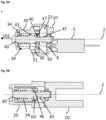
Figures 2A and 2B show sectional views of the clutch actuator in the open position. -
Figure 3A and 3B show sectional views of the clutch actuator in an intermediate position. -
Figure 4A and 4B show sectional views of the clutch actuator in the closed position. -
Figure 5A and 5B show a front view and a perspective view, respectively, of an alternative second section of a coupling member. - In
FIG. 1 , a first embodiment of aclutch actuator 1 is shown. Theclutch actuator 1 may comprise afirst shaft Fig. 1 two shaft sections, namely afirst shaft section 10 and asecond shaft section 20 are depicted, but any other integer number is possible. Theshaft azimuthal bearing surface 22. In this example the shaft has four of these azimuthal bearing surfaces 22, but only a single one is visible inFig. 1 . Other numbers are as well possible. At least two azimuthal bearing surfaces 22 facing in opposite azimuthal directions are preferred.Reference numeral 101 indicates one of these two azimuthal directions, which is referred to as "first direction", as well. - As shown, the azimuthal bearing surface(s) 22 extend, i.a., parallel to the longitudinal axis in a second direction, being indicated as 102.
- The
clutch actuator 1 may further comprise acoupling member 30. Thecoupling member 30 may as well comprise azimuthal bearing surfaces 32 that may extend in the second direction. The azimuthal bearing surfaces 32 provide for a torque proof bearing of thecoupling member 30 with thefirst shaft coupling member 30 parallel and antiparallel to thesecond direction 102 relative to thefirst shaft coupling member 30 may further comprises a first section (see ref. numeral 30), asecond section 60 and atorsion spring 46. Aleg 47 of thetorsion spring 46 may provide afirst interlocking protrusion 47 extending aspin 47 towards a spindle 40 (seeFig. 2A to 4B ) - The
clutch actuator 1 may further comprise at least one of ahelical spring 34 and thespindle 40, preferably both. Thespindle 40 may have a protrusion 43 (preferably a radial protrusion) which may extend in a void between two adjacent turns of thehelical spring 34. InFIG. 2A theprotrusion 43 compresses thehelical spring 34 towards the open direction (antiparallel to the second direction 102). InFIGs. 3A and4A the protrusion has been rotated to compress the helical spring towards thesecond direction 102. - The spindle may be driven by a
motor 3 which may be coupled by atransmission 8 to thespindle 40. -
FIG. 2A and 2B show the assembledclutch actuator 1 in the open position, i.e. thecoupling member 30 is in its open position. Thehousing spindle 40, and accordingly thespindle 40 is preferably rotatably supported relative to theshaft longitudinal axis 2 of theshaft coupling member 30 are essentially aligned. As can be seen inFIG. 2A the free ends of thehelical spring 34 extend through alongitudinally extending groove 39 of thecoupling member 30 and as well into a longitudinally extending groove 19 of theshaft helical spring 34 is thus axially movable in theshaft coupling member 30, but a rotation of thehelical spring 34 is blocked by the boundary walls of thelongitudinal grooves 19, 39. The movement of thehelical spring 34 parallel and antiparallel to the second direction is preferably limited by afirst spring block 37 and asecond spring block 38. As can be seen best inFIG. 2B , in the open position, the first interlockingprotrusion 47 may be located at the "open" side of thesecond interlocking protrusion 45. Open side means here the side of thesecond interlocking protrusion 45 which faces against thesecond direction 102 or in other words the side which faces in the direction thecoupling member 30 is moved when being moved towards its open position. Thus, an externally applied force on thecoupling member 30 cannot shift the coupling member in thesecond direction 102 towards its closed position. A movement of thecoupling member 30 towards the closed position (without driving the spindle 40) is blocked by the interaction of the first interlockingprotrusion 47 with thesecond interlocking protrusion 45. -
FIG. 3A and 3B show the assembledclutch actuator 1 in an intermediate position between the open and the closed state. Assuming the open state as the starting point, the spindle has been rotated. Hence thefirst protrusion 43 has been moved through a void being formed by a turn of thesecond interlocking protrusion 45, which may like in this example be a helical structure. As well due to the rotation, the spindle'sprotrusion 43 rotated through the winding of thehelical spring 34, thereby shifting thehelical spring 34 in thesecond direction 102. Thehelical spring 34 thus preloads thecoupling member 30 towards its closed position. InFIGs. 3A and 3B it is assumed that thecoupling member 30 is blocked in the intermediate position, but only for illustrative purposes. - Once the assumed blockage is removed, the
coupling member 30 is shifted by the energy being stored in thecompressed spring 34 in the closed position being shown inFIG. 4A and 4B . A non-rotationallyinvariant portion 31 of thecoupling member 30 now extends radially from the corresponding portion of thefirst shaft spindle 40 in the other direction. Thespindle 40 now loads thehelical spring 34 in the open direction (opposite to the second direction 102) until the first interlockingprotrusion 47 abuts thesecond interlocking protrusion 45. Continuing to drive thespindle 40 will cause the first interlockingprotrusion 47 to pass the passage of thesecond interlocking protrusion 45 until the coupling member reaches again the open position as depicted inFIG. 2A and 2B . -
FIG. 5A and 5B show another example of thesecond portion 60 of thecoupling member 30 as shown inFig. 1 Thesecond portion 60 of thecoupling member 30 as shown inFIG. 5A and 5B may replace thesecond portion 60 of thecoupling member 30 of the example being shown inFIG. 1 to 4B . - The
second portion 60 of thecoupling member 30 supports apin 47 and can hence as well be referred to aspin support 60. In this example, the pin support has a first ring segment 61and asegment ring segment 61 being centered relative to thelongitudinal axis 2. In between of the tworing segments elastic pin 47 having a width w 47 extends through the slot and is configured, i.e. located, to abut axially against thesecond interlocking protrusion 45 if pushed in the corresponding direction. The tworing segments flange portion 66. - As shown in
FIG. 5A and 5B , the first interlocking protrusion 47 ("thepin 47") may be a free leg of an elastic wire. Thefree leg 47 may be attached to fixedleg 48, which may as well be referred to asattachment leg 48. Theattachment leg 48 may be located in a groove in the outer surface of thesecond ring segment 62, and if thepin support 60 is mounted, the attachment leg is located in between of the peripheral surface of thesecond ring surface 62 and the inner surface of the first portion of thecoupling member 30. A pivotal movement of thepin 47 parallel to thelongitudinal axis 3 is limited by theflange portion 66 of thepin support 60 and by the frontal side of the first portion of thecoupling member 30. In the radial direction, a pivotal movement of thepin 47 is limited by the width w 60 to a few degrees or more precisely to an angle of ±α, wherein α ∈ {20°, 15°, 10°, 5°, 2.5°, 1°, 0° }. -
- 1
- clutch actuator
- 2
- longitudinal axis
- 3
- motor
- 10
- first shaft portion / first housing portion
- 19
- longitudinal groove
- 20
- second shaft portion / second housing portion
- 30
- coupling member
- 31
- non-rotationally invariant portion of the
coupling member 30 - 32
- azimuthal bearing surface
- 39
- longitudinal groove
- 34
- helical coil spring
- 37
- first spring block
- 38
- second spring block
- 39
- longitudinal groove
- 40
- spindle
- 43
- protrusion
- 45
- second interlocking protrusion, e.g. helical structure
- 46
- helical torsion spring (part of coupling member)
- 47
- first interlocking protrusion / pin / free leg of helical torsion spring
- 48
- attachment leg / attachment portion of first interlocking protrusion
- 60
- pin support (part of coupling member)
- 61
- first ring segment
- 62
- second ring segment
- 66
- flange portion
- 101
- first direction
- 102
- second direction
Claims (17)
- A clutch actuator (1) for a door lock, the clutch actuator (1) comprising:- a first shaft (10, 20) with a longitudinal shaft axis (2) and an azimuthal bearing surface (22), wherein∘ the azimuthal bearing surface (22) provides a first block against a rotation in a first direction (101),∘ the first direction (101) is an azimuthal direction and∘ the first block extends in at least one second direction (102)∘ the first and the second direction are linearly independent;- a coupling member (30), being movably supported relative to the first shaft (10,20) by the bearing surface (22) between an open position and a closed position, wherein the coupling member (30) has at least a first spring block (37) and a second spring block (38) and wherein the first spring block (37) and the second spring block (38) face in mutually opposite directions, said mutual opposite directions being parallel to a third direction;- at least one helical spring (34) is movably supported relative to the first shaft (10, 20) to enable a movement parallel to the third direction, wherein the movement parallel to the third direction is limited in the third direction by the first spring block (37) and in the opposite direction by the second spring block (38) and wherein the helical spring (34) has multiple windings;- a spindle (40), wherein the spindle (40) is torque proof connected to a motor shaft and rotatably supported relative to the first shaft (10,20), wherein a protrusion (43) of the spindle (40) is configured to engage in a void between two adjacent turns of the helical spring (34);characterized in that(i) the coupling member (30) has a first interlocking protrusion (47) extending towards the spindle (40),(ii) the spindle (40) has a second interlocking protrusion (45) extending towards the coupling member (30),(iii) in the open position of the coupling member (30) the second interlocking protrusion intersects (45) the path of the first interlocking protrusion (47) when the coupling member (30) is moved from the open position to the closed position.
- The clutch actuator of claim 1,
characterized in that
at least one of the first interlocking protrusion (47) and the second interlocking protrusion (45) is a helical structure aligned with a spindle axis. - The clutch actuator of claim 1 or 2,
characterized in that
one of the first interlocking protrusion (47) and the second interlocking protrusion (45) is a pin. - The clutch actuator of claim 3,
characterized in that
the pin (47) is or comprises a leg (47) of a torsion spring (46). - The clutch actuator of one of claims 1 to 4,
characterized in that
the sum of the widths of the first interlocking protrusion (47) and the second interlocking protrusions (45) measured parallel to the second direction (102) is smaller than the distance the coupling member is moved in the third direction by four revolutions of the spindle (40). - The clutch actuator of one of claims 1 or 2,
characterized in that
the first interlocking protrusion (47) has a first passage and the second interlocking protrusion (45) has a second passage, wherein the first interlocking protrusion (47) fits into the second passage and the second interlocking protrusion (45) fits into the first passage. - The clutch actuator (1) of one of the previous claims characterized in that the first spring block (37) faces against the second direction and the second spring block (38) faces in the third direction
- The clutch actuator (1) of one of the previous claims, characterized in that the second direction is parallel to the longitudinal axis (2) or parallel to the radial direction.
- The clutch actuator (1) of one of the previous claims, characterized in that the third direction is parallel to the second direction (102).
- The clutch actuator of one of the previous claims, characterized in that that the first shaft (10, 20) and the coupling member (30) are two parts of a telescopic shaft.
- The clutch actuator (1) of one of the previous claims, characterized in that the coupling member (30) has a grove (39) having a longitudinal groove direction, wherein the longitudinal groove direction is parallel to the third direction.
- The clutch actuator of one of claims 11, characterized that the at least one of the ends of the helical spring (34) engages into the longitudinal groove (39)
- A door lock clutch, characterized in that it comprises the clutch actuator (1) of one of the previous claims and a second shaft with a second azimuthal abutment and in that the coupling member when in its open position does azimuthally overlap with the second abutment and when in its closed position the coupling member azimuthally overlaps with a portion of the coupling member.
- A door handle comprising at least:- a clutch having an input shaft and an output shaft,- a handle lever being torque proof connected to the input shaft characterized in that the clutch is the clutch of claim 13 and in that(i) the first shaft (10, 20) is the input shaft and the second shaft is the output shaft, or(ii) in that first shaft (10, 20) is the output shaft and in that the second shaft is the input put shaft.
- A door lock comprising a latch bolt and/or a dead lock, characterized in that the first shaft or the second shaft of the clutch of claim 13 is coupled via a transmission to a latch bolt and/or a dead lock and the respective other shaft is configured to be driven by an operator.
- A method for closing a door lock clutch, comprising:(i) moving a coupling member (30) being movably but torque proof connected to a first shaft (10, 20) with respect to a first direction (101), which first direction (101) is an azimuthal direction of a longitudinal axis (2) of the first shaft, from an open position in a second direction (102) towards a second shaft of the door lock clutch,(ii) prior to or while said moving: rotating a first interlocking protrusion (47) of the coupling member (30) through a passage in a second interlocking protrusion (45) and the second interlocking protrusion (45) through a passage of the first interlocking member (47).
- The method of the previous claim, characterized in that moving the coupling member (30) comprises loading a first spring (34) being force transmittingly connected to the coupling member (30) towards the third direction to thereby apply a force in the third direction to the coupling member (30).
Priority Applications (1)
| Application Number | Priority Date | Filing Date | Title |
|---|---|---|---|
| EP22171351.4A EP4273355A1 (en) | 2022-05-03 | 2022-05-03 | Clutch actuator for a door lock |
Applications Claiming Priority (1)
| Application Number | Priority Date | Filing Date | Title |
|---|---|---|---|
| EP22171351.4A EP4273355A1 (en) | 2022-05-03 | 2022-05-03 | Clutch actuator for a door lock |
Publications (1)
| Publication Number | Publication Date |
|---|---|
| EP4273355A1 true EP4273355A1 (en) | 2023-11-08 |
Family
ID=81580092
Family Applications (1)
| Application Number | Title | Priority Date | Filing Date |
|---|---|---|---|
| EP22171351.4A Pending EP4273355A1 (en) | 2022-05-03 | 2022-05-03 | Clutch actuator for a door lock |
Country Status (1)
| Country | Link |
|---|---|
| EP (1) | EP4273355A1 (en) |
Citations (12)
| Publication number | Priority date | Publication date | Assignee | Title |
|---|---|---|---|---|
| GB2262770A (en) | 1991-12-27 | 1993-06-30 | Talleres Escoriaza Sa | A clutch device for electric locks |
| WO1998015703A1 (en) * | 1996-10-08 | 1998-04-16 | Lucky Lock Ltd. | Electro-mechanical lock |
| DE19854454A1 (en) | 1998-11-13 | 2000-06-08 | Ulf Klenk | Lock cylinder has electrically operated coupling element that penetrates holes to form shape-locking connection between inner surface of first shaft and outer surface of second shaft |
| WO2003071060A1 (en) | 2002-02-25 | 2003-08-28 | Dom-Sicherheitstechnik Gmbh & Co. Kg | Access control system, installation and method |
| DE10235201A1 (en) | 2002-08-01 | 2004-02-19 | Günter Uhlmann | Door closure system for building complex has operating module coupled to cylinder module inserted in door lock opening in dependence on authorization code provided by key |
| EP1710753A2 (en) | 2005-04-08 | 2006-10-11 | Computerized Security Systems | Door lock with RFID key |
| EP1787241B1 (en) | 2004-08-26 | 2010-05-26 | Nxp B.V. | Rfid tag having a folded dipole |
| EP2195767A1 (en) | 2007-09-05 | 2010-06-16 | Confidex OY | Rfid transponder and method |
| EP2473690A1 (en) | 2009-08-31 | 2012-07-11 | Kaba AG | Locking device |
| EP2860331A1 (en) * | 2013-10-08 | 2015-04-15 | Assa Ab | Handle device |
| US9181730B1 (en) * | 2014-12-18 | 2015-11-10 | Fu-Chang Peng | Driving structure of electronic lock |
| US10927569B2 (en) | 2015-08-05 | 2021-02-23 | Uhlmann & Zacher Gmbh | Door handle and drive support for an electromagnetic door lock |
-
2022
- 2022-05-03 EP EP22171351.4A patent/EP4273355A1/en active Pending
Patent Citations (12)
| Publication number | Priority date | Publication date | Assignee | Title |
|---|---|---|---|---|
| GB2262770A (en) | 1991-12-27 | 1993-06-30 | Talleres Escoriaza Sa | A clutch device for electric locks |
| WO1998015703A1 (en) * | 1996-10-08 | 1998-04-16 | Lucky Lock Ltd. | Electro-mechanical lock |
| DE19854454A1 (en) | 1998-11-13 | 2000-06-08 | Ulf Klenk | Lock cylinder has electrically operated coupling element that penetrates holes to form shape-locking connection between inner surface of first shaft and outer surface of second shaft |
| WO2003071060A1 (en) | 2002-02-25 | 2003-08-28 | Dom-Sicherheitstechnik Gmbh & Co. Kg | Access control system, installation and method |
| DE10235201A1 (en) | 2002-08-01 | 2004-02-19 | Günter Uhlmann | Door closure system for building complex has operating module coupled to cylinder module inserted in door lock opening in dependence on authorization code provided by key |
| EP1787241B1 (en) | 2004-08-26 | 2010-05-26 | Nxp B.V. | Rfid tag having a folded dipole |
| EP1710753A2 (en) | 2005-04-08 | 2006-10-11 | Computerized Security Systems | Door lock with RFID key |
| EP2195767A1 (en) | 2007-09-05 | 2010-06-16 | Confidex OY | Rfid transponder and method |
| EP2473690A1 (en) | 2009-08-31 | 2012-07-11 | Kaba AG | Locking device |
| EP2860331A1 (en) * | 2013-10-08 | 2015-04-15 | Assa Ab | Handle device |
| US9181730B1 (en) * | 2014-12-18 | 2015-11-10 | Fu-Chang Peng | Driving structure of electronic lock |
| US10927569B2 (en) | 2015-08-05 | 2021-02-23 | Uhlmann & Zacher Gmbh | Door handle and drive support for an electromagnetic door lock |
Non-Patent Citations (1)
| Title |
|---|
| BRONSHTEIN, SEMENDAYEVMUSIOL, MUEHLIG: "Handbook of Mathematics", SPRINGER |
Similar Documents
| Publication | Publication Date | Title |
|---|---|---|
| JP3350525B2 (en) | Cylinder lock | |
| US9850686B2 (en) | Handle device | |
| EP2994586B1 (en) | Electromechanical cylinder lock with key override | |
| US8336346B2 (en) | High security moving mass lock system | |
| AU2007219023A1 (en) | Safety mechanism for locks | |
| AU2017331936B2 (en) | Handle device | |
| GB2492829A (en) | Double lock cylinder with key cylinder, thumbturn, and mis-alignment clutch | |
| KR20180005888A (en) | Door locking device | |
| EP4273355A1 (en) | Clutch actuator for a door lock | |
| EP4097314A1 (en) | Thumbturn lock actuator | |
| US20060196238A1 (en) | Door locking system | |
| TW202104739A (en) | Symmetrical and reversible-clutch mortise lock | |
| KR102267632B1 (en) | Digital door lock | |
| EP4019719B1 (en) | Locking device | |
| EP4365390A1 (en) | Cabinet lock | |
| EP4112852A1 (en) | Eccentric locking mechanism for an electronic cylinder lock and electronic cylinder lock provided with said locking mechanism | |
| KR101249937B1 (en) | Door lock having panic function | |
| WO2023222129A1 (en) | Lockset and locking device | |
| WO2021251896A2 (en) | Adapter for a locking device | |
| RU2680893C1 (en) | Anti-theft device for a vehicle | |
| JP2591708B2 (en) | Lock device | |
| CN110886543A (en) | Coupling device for a door fitting, door fitting system and method for coupling or uncoupling a coupling device | |
| HU205190B (en) | Structural arrangement for operating locks firtst the safety locks of entrance doors |
Legal Events
| Date | Code | Title | Description |
|---|---|---|---|
| PUAI | Public reference made under article 153(3) epc to a published international application that has entered the european phase |
Free format text: ORIGINAL CODE: 0009012 |
|
| STAA | Information on the status of an ep patent application or granted ep patent |
Free format text: STATUS: THE APPLICATION HAS BEEN PUBLISHED |
|
| AK | Designated contracting states |
Kind code of ref document: A1 Designated state(s): AL AT BE BG CH CY CZ DE DK EE ES FI FR GB GR HR HU IE IS IT LI LT LU LV MC MK MT NL NO PL PT RO RS SE SI SK SM TR |
|
| STAA | Information on the status of an ep patent application or granted ep patent |
Free format text: STATUS: REQUEST FOR EXAMINATION WAS MADE |
|
| 17P | Request for examination filed |
Effective date: 20231120 |
|
| RBV | Designated contracting states (corrected) |
Designated state(s): AL AT BE BG CH CY CZ DE DK EE ES FI FR GB GR HR HU IE IS IT LI LT LU LV MC MK MT NL NO PL PT RO RS SE SI SK SM TR |
|
| GRAP | Despatch of communication of intention to grant a patent |
Free format text: ORIGINAL CODE: EPIDOSNIGR1 |
|
| STAA | Information on the status of an ep patent application or granted ep patent |
Free format text: STATUS: GRANT OF PATENT IS INTENDED |
|
| RIC1 | Information provided on ipc code assigned before grant |
Ipc: E05B 15/04 20060101ALN20240131BHEP Ipc: E05B 47/00 20060101ALN20240131BHEP Ipc: E05B 47/06 20060101ALI20240131BHEP Ipc: E05B 17/20 20060101AFI20240131BHEP |
|
| RIC1 | Information provided on ipc code assigned before grant |
Ipc: E05B 15/04 20060101ALN20240207BHEP Ipc: E05B 47/00 20060101ALN20240207BHEP Ipc: E05B 47/06 20060101ALI20240207BHEP Ipc: E05B 17/20 20060101AFI20240207BHEP |
|
| INTG | Intention to grant announced |
Effective date: 20240306 |
|
| GRAJ | Information related to disapproval of communication of intention to grant by the applicant or resumption of examination proceedings by the epo deleted |
Free format text: ORIGINAL CODE: EPIDOSDIGR1 |
|
| STAA | Information on the status of an ep patent application or granted ep patent |
Free format text: STATUS: REQUEST FOR EXAMINATION WAS MADE |
|
| STAA | Information on the status of an ep patent application or granted ep patent |
Free format text: STATUS: EXAMINATION IS IN PROGRESS |
|
| INTC | Intention to grant announced (deleted) |