EP4249751A1 - Control device for a peristaltic pump, peristaltic pump, injection device and method for controlling a peristaltic pump - Google Patents
Control device for a peristaltic pump, peristaltic pump, injection device and method for controlling a peristaltic pump Download PDFInfo
- Publication number
- EP4249751A1 EP4249751A1 EP23160540.3A EP23160540A EP4249751A1 EP 4249751 A1 EP4249751 A1 EP 4249751A1 EP 23160540 A EP23160540 A EP 23160540A EP 4249751 A1 EP4249751 A1 EP 4249751A1
- Authority
- EP
- European Patent Office
- Prior art keywords
- pressure
- cycle
- phase
- printing
- volume flow
- Prior art date
- Legal status (The legal status is an assumption and is not a legal conclusion. Google has not performed a legal analysis and makes no representation as to the accuracy of the status listed.)
- Pending
Links
- 230000002572 peristaltic effect Effects 0.000 title claims abstract description 48
- 238000002347 injection Methods 0.000 title claims description 50
- 239000007924 injection Substances 0.000 title claims description 50
- 238000000034 method Methods 0.000 title claims description 30
- 230000001105 regulatory effect Effects 0.000 claims abstract description 13
- 238000001514 detection method Methods 0.000 claims description 21
- 239000003795 chemical substances by application Substances 0.000 claims description 13
- 230000008569 process Effects 0.000 claims description 13
- 230000008859 change Effects 0.000 claims description 9
- 238000013213 extrapolation Methods 0.000 claims description 5
- 241001465754 Metazoa Species 0.000 claims description 3
- 238000011038 discontinuous diafiltration by volume reduction Methods 0.000 claims description 2
- 238000009499 grossing Methods 0.000 claims description 2
- 238000012937 correction Methods 0.000 description 9
- 238000010586 diagram Methods 0.000 description 6
- 239000002872 contrast media Substances 0.000 description 4
- 230000008901 benefit Effects 0.000 description 3
- 230000033228 biological regulation Effects 0.000 description 3
- 230000001276 controlling effect Effects 0.000 description 3
- 230000007423 decrease Effects 0.000 description 3
- 238000005259 measurement Methods 0.000 description 3
- 230000010349 pulsation Effects 0.000 description 3
- 238000005086 pumping Methods 0.000 description 3
- 230000002123 temporal effect Effects 0.000 description 3
- 238000004364 calculation method Methods 0.000 description 2
- 230000001419 dependent effect Effects 0.000 description 2
- 230000010354 integration Effects 0.000 description 2
- 239000007788 liquid Substances 0.000 description 2
- 230000035484 reaction time Effects 0.000 description 2
- 230000004044 response Effects 0.000 description 2
- 230000007704 transition Effects 0.000 description 2
- FAPWRFPIFSIZLT-UHFFFAOYSA-M Sodium chloride Chemical compound [Na+].[Cl-] FAPWRFPIFSIZLT-UHFFFAOYSA-M 0.000 description 1
- 230000003321 amplification Effects 0.000 description 1
- 238000013459 approach Methods 0.000 description 1
- 239000000872 buffer Substances 0.000 description 1
- 238000005352 clarification Methods 0.000 description 1
- 230000006835 compression Effects 0.000 description 1
- 238000007906 compression Methods 0.000 description 1
- 238000002591 computed tomography Methods 0.000 description 1
- 125000004122 cyclic group Chemical group 0.000 description 1
- 230000003247 decreasing effect Effects 0.000 description 1
- 238000011161 development Methods 0.000 description 1
- 230000000694 effects Effects 0.000 description 1
- 230000006870 function Effects 0.000 description 1
- 238000003384 imaging method Methods 0.000 description 1
- 230000006872 improvement Effects 0.000 description 1
- 238000001990 intravenous administration Methods 0.000 description 1
- 238000010253 intravenous injection Methods 0.000 description 1
- 238000004519 manufacturing process Methods 0.000 description 1
- 239000000463 material Substances 0.000 description 1
- 239000012528 membrane Substances 0.000 description 1
- 238000003199 nucleic acid amplification method Methods 0.000 description 1
- 230000010355 oscillation Effects 0.000 description 1
- 230000002028 premature Effects 0.000 description 1
- 230000009467 reduction Effects 0.000 description 1
- 238000004904 shortening Methods 0.000 description 1
- 230000003068 static effect Effects 0.000 description 1
- 238000003325 tomography Methods 0.000 description 1
Images


Classifications
-
- A—HUMAN NECESSITIES
- A61—MEDICAL OR VETERINARY SCIENCE; HYGIENE
- A61M—DEVICES FOR INTRODUCING MEDIA INTO, OR ONTO, THE BODY; DEVICES FOR TRANSDUCING BODY MEDIA OR FOR TAKING MEDIA FROM THE BODY; DEVICES FOR PRODUCING OR ENDING SLEEP OR STUPOR
- A61M5/00—Devices for bringing media into the body in a subcutaneous, intra-vascular or intramuscular way; Accessories therefor, e.g. filling or cleaning devices, arm-rests
- A61M5/14—Infusion devices, e.g. infusing by gravity; Blood infusion; Accessories therefor
- A61M5/142—Pressure infusion, e.g. using pumps
- A61M5/14212—Pumping with an aspiration and an expulsion action
- A61M5/14232—Roller pumps
-
- F—MECHANICAL ENGINEERING; LIGHTING; HEATING; WEAPONS; BLASTING
- F04—POSITIVE - DISPLACEMENT MACHINES FOR LIQUIDS; PUMPS FOR LIQUIDS OR ELASTIC FLUIDS
- F04B—POSITIVE-DISPLACEMENT MACHINES FOR LIQUIDS; PUMPS
- F04B43/00—Machines, pumps, or pumping installations having flexible working members
- F04B43/12—Machines, pumps, or pumping installations having flexible working members having peristaltic action
- F04B43/1253—Machines, pumps, or pumping installations having flexible working members having peristaltic action by using two or more rollers as squeezing elements, the rollers moving on an arc of a circle during squeezing
-
- F—MECHANICAL ENGINEERING; LIGHTING; HEATING; WEAPONS; BLASTING
- F04—POSITIVE - DISPLACEMENT MACHINES FOR LIQUIDS; PUMPS FOR LIQUIDS OR ELASTIC FLUIDS
- F04B—POSITIVE-DISPLACEMENT MACHINES FOR LIQUIDS; PUMPS
- F04B49/00—Control, e.g. of pump delivery, or pump pressure of, or safety measures for, machines, pumps, or pumping installations, not otherwise provided for, or of interest apart from, groups F04B1/00 - F04B47/00
- F04B49/08—Regulating by delivery pressure
-
- F—MECHANICAL ENGINEERING; LIGHTING; HEATING; WEAPONS; BLASTING
- F04—POSITIVE - DISPLACEMENT MACHINES FOR LIQUIDS; PUMPS FOR LIQUIDS OR ELASTIC FLUIDS
- F04B—POSITIVE-DISPLACEMENT MACHINES FOR LIQUIDS; PUMPS
- F04B49/00—Control, e.g. of pump delivery, or pump pressure of, or safety measures for, machines, pumps, or pumping installations, not otherwise provided for, or of interest apart from, groups F04B1/00 - F04B47/00
- F04B49/20—Control, e.g. of pump delivery, or pump pressure of, or safety measures for, machines, pumps, or pumping installations, not otherwise provided for, or of interest apart from, groups F04B1/00 - F04B47/00 by changing the driving speed
-
- A—HUMAN NECESSITIES
- A61—MEDICAL OR VETERINARY SCIENCE; HYGIENE
- A61M—DEVICES FOR INTRODUCING MEDIA INTO, OR ONTO, THE BODY; DEVICES FOR TRANSDUCING BODY MEDIA OR FOR TAKING MEDIA FROM THE BODY; DEVICES FOR PRODUCING OR ENDING SLEEP OR STUPOR
- A61M5/00—Devices for bringing media into the body in a subcutaneous, intra-vascular or intramuscular way; Accessories therefor, e.g. filling or cleaning devices, arm-rests
- A61M5/007—Devices for bringing media into the body in a subcutaneous, intra-vascular or intramuscular way; Accessories therefor, e.g. filling or cleaning devices, arm-rests for contrast media
Definitions
- the invention relates to a control device for a peristaltic pump according to the preamble of claim 1, a peristaltic pump with such a control device, an injection device with such a peristaltic pump and a method for controlling a peristaltic pump.
- Injection devices are medical devices with which liquid injection agents (medium) can be introduced into a human or animal body in a controlled manner using a pump device.
- the injection agent can be, for example, a contrast agent for increasing the contrast in an imaging method, such as computer tomography or magnetic resonance tomography.
- a contrast agent for increasing the contrast in an imaging method, such as computer tomography or magnetic resonance tomography.
- known injection devices provide controls or regulations that switch off the injection device or its pumping device when a permissible pressure limit (maximum target pressure), which is below a defined dangerous pressure, is exceeded.
- pressure maxima can occur that are only briefly and slightly above the pressure limit and therefore lead to the pump device being switched off unnecessarily or the injection process being aborted. This prolongs the injection process and unnecessarily increases the total injected volume of injectable.
- US 6,673,033 B1 proposed to define an intermediate pressure threshold, if it is exceeded, the performance of a pumping device is initially throttled, and to only switch off the pumping device when the pressure in a hose line of an injector rises above a pressure limit despite the throttled performance.
- a temporal criterion is used as the criterion for terminating an injection process Integral of the pressure curve from the time a pressure limit is exceeded should be used as a benchmark for terminating the injection process, so that short-term pressure peaks can be tolerated and a short-term exceeding of the pressure limit does not lead to an immediate termination of the injection process.
- a peristaltic pump with an oscillating pressure curve pressure pulsation
- a peristaltic pump with such a control device an injection device with such a peristaltic pump and a control method in which safety intervals are reduced and a predetermined pressure limit is closer can be brought to a dangerous pressure without increasing the risk of harm to the patient and/or the material of the injection device.
- pressure pulsations should be reduced.
- control device of claim 1 the peristaltic pump according to claim 12, an injection device according to claim 14 and a control method according to claim 15.
- the control device is used to control a peristaltic pump with a squeeze hose and cyclically moving conveying elements for conveying a medium guided in the squeeze hose during a conveying process with a controlled volume flow into an output line connected to the squeeze hose.
- the conveying elements compress the squeeze tube cyclically, so that a pressure is established in the output line with a pressure curve that has cyclically repeating pressure cycles.
- Each printing cycle can be defined in such a way that it extends, for example, from a pressure minimum through a pressure increase to a pressure maximum and then drops again to a pressure minimum of a subsequent printing cycle.
- the control device regulates a speed of the peristaltic pump - in the case of a roller pump, this can be an angular speed of a conveying element act - in such a way that a maximum volume flow is achieved without a pressure limit in the output line being exceeded.
- the pressure limit can be a desired, still permissible target pressure.
- the control device has at least a first control circuit for regulating the maximum volume flow. This receives a target volume flow and the pressure limit as externally specified reference variables.
- the control device is set up to carry out a control method in which a prediction pressure for an expected maximum pressure within the pressure cycle is calculated for each pressure cycle based on at least the pressure in the output line and the maximum volume flow is limited, taking the prediction pressure into account, so that the pressure in the output line does not exceed the pressure limit in the printing cycle.
- the first control loop expediently records the current pressure in the output line as a feedback variable, based on which a control part of the control loop controls the maximum volume flow in a predictive manner.
- the speed of the peristaltic pump can be adjusted early and proactively and, in particular, reduced if the pressure limit is threatened to be exceeded. Since reaction times are extended by the pressure forecast, safety reserves increase. Pressure limits that are still permissible can then be brought closer to critical pressure values, such as a danger pressure, which in turn means higher volume flows and thus, for example, a shortening of the injection duration for a specific injection volume. Since the importance of fast-reacting mechanics becomes less important with predictive control, more inert components can also be used for the peristaltic pump, which makes the production of the peristaltic pump cheaper. Calibration of the control process is not necessary if the control device is designed appropriately.
- the first control circuit includes a printing phase detection, through which the end of a previous printing cycle and the beginning of a subsequent printing cycle are recognized.
- the detection can take place based on a characteristic size of the pressure curve in the output line, in particular a defined pressure drop compared to a pressure maximum of the previous printing cycle.
- the start of a printing cycle can, for example, be defined at the point in time a pressure drop compared to the (absolute) pressure maximum of the previous pressure cycle by more than a certain relative amount, for example by at least 1/6, 1 ⁇ 4 or 1/3 or - regardless of the previous pressure maximum - by an absolute amount, for example at least 2 bar, occurs.
- the pressure drop is advantageously chosen to be so large that this pressure drop only occurs once towards the end of a printing cycle. The occurrence of this pressure drop is then sufficiently robust to indicate the start of a subsequent pressure cycle. Should a typical printing cycle have larger pressure fluctuations, larger pressure drops and/or incremental counters can be used as an alternative, which count the number of pressure drops by a certain minimum amount in order to detect the start of a subsequent printing cycle.
- each pressure cycle is divided into successive pressure phases based on predefined characteristics and the pressure phase detection detects the beginning of the individual pressure phases, the prediction pressure being used to control the maximum volume flow in the first control loop only in certain pressure phases and ignored or not used in other printing phases.
- the regulation is therefore discontinuous.
- An advantage of such a pressure phase-dependent control is that the pressure prediction can be used precisely in the pressure phases in which the development of the pressure in the output line is dynamic and the pressure limit can be exceeded comparatively suddenly, so that the maximum volume flow is conservative in these pressure phases is regulated, while it can be regulated more aggressively in other pressure phases, since a sudden exceeding of the pressure limit is not to be expected in these other pressure phases.
- a further advantage is that different controls can be implemented for different pressure phases, for example by switching on or switching off additional control loops that are superimposed on the first control loop and/or by changing the control parameters of the first control loop, such as the gain factors used therein or the like.
- the aforementioned predefined characteristics may be absolute or relative pressure changes and/or an absolute or relative pressure change rate of the pressure in the output line.
- the predefined characteristics do not necessarily have to be point values. For example, it is possible to choose moving averages over specific time periods, such as 0.1, 0.2 or 0.5 seconds.
- the recognition of the individual pressure phases by the pressure phase detection can be done based on the predefined characteristics. Alternatively, however, individual pressure phases can also be recognized based on a position of the conveying elements of the peristaltic pump through the pressure phase detection, since the positions of the conveying elements - as explained in more detail below - correlate with the individual pressure phases. It is also possible to combine the detection based on predefined characteristics and a position determination of the conveying elements for the printing phase detection, be it at the same time in order to make the printing phase detection of individual printing phases redundant or be it in order to detect individual printing phases based on the defined characteristics and other printing phases based on the position of the Determine conveying elements.
- the pressure phase detection is preferably designed redundantly to increase reliability. This makes it possible to reduce susceptibility to errors and, in particular, requirements for the reliability of individual components, and thus component costs.
- the printing cycle is characterized by five successive printing phases, with a first printing phase characterized by a rapid pressure loss, a second printing phase characterized by a rapid pressure increase, a third printing phase characterized by a flat pressure increase, a fourth printing phase characterized by a moderate pressure increase and a fifth printing phase is characterized by a pressure plateau with essentially constant pressure, and each pressure phase is recognized by the pressure phase detection.
- a division of a pressure cycle is a good approximation for pressure cycles in injection devices for intravenous injection of, for example, contrast agents.
- the static and dynamic pressure resistances in the output line (and the adjoining lines) are responsible for the individual pressure phases, which arise in particular from opening and closing check valves, throttles, the mass inertia of the medium to be pumped and other influences.
- the printing phases can also be defined differently than in the example above.
- the prediction pressure for controlling the maximum volume flow is only used in the fourth pressure phase, i.e. the pressure phase before the pressure plateau with the (absolute) pressure maximum within the pressure cycle.
- the fourth printing phase is advantageously defined in a range that ranges from approximately 50% to approximately 80% of a phase progression of the printing cycle.
- Phase progression is understood to mean the printing cycle in time resolution, i.e. the printing cycle begins at 0% phase progression - this corresponds, for example, to a pressure minimum - and ends at 100% - this then corresponds to the pressure minimum of the subsequent printing cycle.
- the forecast pressure is 'connected' to the first control loop in the fourth pressure phase to calculate the maximum volume flow, and is otherwise 'switched off', it is a discontinuous controller.
- the prediction pressure By limiting the use of the prediction pressure in this way, a complex calculation of the prediction pressure in the other printing phases can be dispensed with.
- the prediction pressure can be achieved via a linear extrapolation of the current pressure increase in the output line to a specific (calculated) phase progress, which is preferably in the range of 80% to 95% of the total phase progress and, for example, at 80%, 90% or 95% of the total phase progress and in particular 87% of the total phase progress can be determined.
- a specific (calculated) phase progress which is preferably in the range of 80% to 95% of the total phase progress and, for example, at 80%, 90% or 95% of the total phase progress and in particular 87% of the total phase progress can be determined.
- the specific (calculated) phase progress that is used to determine the forecast pressure is expediently chosen to be fixed and is, for example, a constant 87% of the total phase progress.
- This particular phase progression can - but does not have to - correspond to the real phase progression at which real pressure maxima occur in the pressure cycles. Actual pressure maxima can therefore occur at actual phase progressions that lie before or behind the specific (calculated) phase progression of, in the example, 87% of the total phase progression.
- the specific phase progress is preferably selected and set mathematically so that prediction pressures are achieved that correspond as accurately as possible to the actual pressure maxima successive print cycles.
- the specific (computational) phase progression to which the forecast pressure is extrapolated can be shifted to the real phase progression at which a real pressure maximum occurs, if this results in better forecast pressures.
- the control device controls a roller pump.
- Roller pumps have the advantage that there are no changes in direction, which is why roller pumps are particularly suitable for precise dosing of injection boluses in injection devices. Since the medium conveyed in roller pumps is conveyed in a squeeze hose, there is no direct contact between the medium conveyed and the pump in roller pumps, which is advantageous for hygienic reasons. Furthermore, the squeeze hose can be easily replaced.
- the invention therefore also relates to a roller pump with a rotatable rotor, a plurality of conveying elements for squeezing a squeeze hose, which are designed as rollers (squeeze rollers) arranged on the rotor, the squeeze hose being mounted along a hose bed with an inlet area and an outlet area and
- the conveying elements successively squeeze a section of the squeeze hose in a fluid-tight manner when the conveying elements enter the hose bed at the level of the inlet area and until the conveying elements exit the hose bed at the level of the outlet area and thereby a medium located in the squeeze hose in the direction of rotation in the opposite direction Promote dynamic pressure in an output line connected to the squeeze hose into the output line, the roller pump containing a control device according to the invention.
- a volume of the squeeze tube located in front of the outlet area is compressed from a maximum volume to a minimum volume until a conveying element emerges from the hose bed at the level of the outlet area, releasing the section of the squeeze tube squeezed by this conveying element and thus that located in front of the outlet area Volume of the squeeze tube increased from the minimum volume to the maximum volume.
- the volume reduction and volume increase of the volume in front of the outlet area together represent a complete printing cycle.
- the roller pump also has n preferably radially uniformly distributed conveying elements, so that the roller pump carries out n pump strokes with n pressure cycles when the rotor rotates completely through 360°.
- the number of role elements is, for example, three.
- each conveying element is only involved in a printing cycle in a certain angular section, namely in the angular section in which the conveying element represents the "leading" role in relation to the outlet area or the output line, the angular position of the conveying element correlates with the phase progress in this angular section of the printing cycle.
- individual angular ranges of the angular position of the conveying elements within the angular section also correlate with individual printing phases of a printing cycle.
- the pressure phase to be determined based on the angular position of one of the conveying elements, in particular a 'leading' conveying element.
- the printing phase detection of the control device determines the start of at least one printing phase of a printing cycle via an angular position of a conveying element.
- the angular position is expediently determined indirectly, for example via the temporal integration of the angular velocity of the conveying elements or the rotor of the roller pump.
- the angular velocity of the rotor is usually available directly via a roller pump control unit.
- an absolute angular position of the leading conveying element can be approximated via a pressure drop by a minimum amount.
- the first control circuit comprises a mean value filter which adapts the maximum volume flow depending on a maximum pressure temporarily stored in the control device of a pressure cycle immediately preceding the current pressure cycle. This allows errors in the measurement of the pressure in the output line to be compensated for.
- the mean value filter can dampen the oscillation behavior of the control loop and, in particular, prevent or at least reduce overshoot of the controlled variable.
- the previous measured maximum pressure is used as a ratio of the measured maximum pressure to the pressure limit (target pressure) is returned to the first control loop and a new target volume flow is set based on this. A deviation between the actual maximum pressure and the pressure limit (target pressure) can be reduced with each cycle.
- the first control circuit is advantageously a PID controller with a proportional element, an integral element and a differential element.
- a PID controller enables the controlled variable to approach the reference variables quickly and accurately.
- the prediction pressure for regulating the maximum volume flow is preferably processed in the differential element.
- further feedback variables for example a rate of change in a rotational speed of a rotor of a peristaltic pump and/or a rate of change in the volume flow, can also be taken into account in the differential element.
- the differential element is advantageously set to 0 in certain pressure phases. In this way, advance control intervention can be switched off if necessary.
- control device can include a control for smoothing pressure peaks in pressure cycles.
- the control is advantageously a speed adapter.
- the speed adapter is preferably set up in such a way that at a certain progress in the pressure cycle, a target speed of a conveying element of the peristaltic pump is reduced by a certain amount to a reduced target speed compared to an average target speed before the completion of a printing cycle and/or after completion of a Printing cycle is increased by a certain amount to an increased target speed and is held for a certain holding period.
- the speed of the conveying elements increases suddenly to the increased target speed and is then reduced linearly to the reduced target speed of the conveying element after the holding period. This allows load peaks to be reduced.
- All holding periods can be the same or different lengths.
- the increase and decrease in the target speed is expediently of the same magnitude.
- the speed of the peristaltic pump can, for example, be increased or decreased as a percentage by a predetermined proportion of the average target speed, the change in speed preferably being between 20% and 40% of the average target speed and in particular at 20%, 30% or 40% can be above or below the average target speed.
- the control is superimposed on the first control loop via a speed adapter.
- the change caused by the control can be taken into account as a modified reference variable of the target rotational speed in the first control loop.
- the rotational speed and the target volume flow are viewed as being directly proportional to one another and therefore interchangeable.
- the influences of the first control loop with the pressure prediction and the influences of the control reinforce each other, so that the control quality of the control device can be increased disproportionately.
- the delivery process of a peristaltic pump regularly includes more than one, in particular more than five and particularly preferably more than ten pressure cycles.
- an injection device for injecting an injection agent into an animal or human body using a peristaltic pump designed as a roller pump which has a control device according to the invention to regulate the roller pump.
- a control device to regulate the roller pump.
- a control method for a peristaltic pump which has a squeeze hose and cyclically moving conveying elements for conveying a medium guided in the squeeze hose during a conveying process with a controlled volume flow into an output line connected to the squeeze hose, the conveying elements cyclically compress the squeeze hose so that a pressure curve of a pressure is established in the output line which has cyclically repeating pressure cycles, each pressure cycle having a pressure minimum, a pressure increase, a pressure maximum and a pressure drop, the control method regulating a speed of the peristaltic pump in such a way, that a maximum volume flow is achieved without exceeding a pressure limit in the output line, the control method comprising a first control loop for regulating the maximum volume flow, which receives a target volume flow and the pressure limit as reference variables, and a prediction pressure for each pressure cycle The expected maximum pressure within the printing cycle is calculated based on the pressure in the output line. The maximum volume flow is then limited, taking the forecast pressure into account, so that
- Fig. 1 shows an injection device 1 for intravenous administration of an injection agent.
- the injection device 1 has a base body mounted on rollers, at the upper end of which several injection agent containers 2a, 2b, 2c are arranged. Contrast medium and a saline solution are stored in the injection medium containers 2a, 2b, 2c.
- the injection agent containers 2a, 2b, 2c are connected to a squeeze hose 4 via an inlet line 3.
- the squeeze tube 4 is inserted into the tube bed 6 of a roller pump 5 and connected on the output side to an output line 9, which in turn can be connected to the bloodstream of a patient via an adjoining patient tube (not shown) via a catheter.
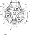
- the roller pump 5 has three rollers 5-1, 5-2, 5-3 rotatably mounted on an electric motor-driven rotor 7, which run along the in Fig. 2 marked hose bed 6 of the peristaltic pump 5 are guided, and the squeeze hose 4 is partially counteracted squeeze a counter bearing of the hose bed 6, so that when the rotor 7 rotates about its axis of rotation, an injection agent located in the squeeze hose 4 is conveyed into the output line 9 in portions against a dynamic pressure in the output line 9.
- the injection device 1 has a control device 8 for controlling the roller pump 5 (and other components of the injection device 1).
- a perspective detailed view of the roller pump 5 is shown.
- the squeeze hose 4 runs over an angular range of approximately 260 ° - based on the axis of rotation 1, 5-2, 5-3 are arranged evenly at an angular distance of 120 ° on the rotor 7, there are always at least two rollers between the inlet area 6-1 and the outlet area 6-2 of the hose bed 6, which hold the squeeze hose 4 against the counter bearing of the hose bed 6.
- the squeeze hose 4 is therefore always squeezed in at least two places during operation of the roller pump.
- the rotor 7 of the peristaltic pump rotates in a direction of rotation - in the illustration Fig. 2 clockwise - so that the squeezed areas of the squeeze hose 4 move in the direction of rotation with the rollers 5-1, 5-2, 5-3.
- a liquid-tight tube section with a certain volume is formed between two squeezed areas, so that the injection agent contained therein is encapsulated between two rollers 5-1, 5-2, 5-3 and is moved in the direction of rotation up to the outlet area 6-2. If a roller 5-1 begins to lift off the hose bed 6 in the outlet area 6-2, the injection agent can be conveyed in the hose section against the dynamic pressure prevailing in the remaining part of the output line 9.
- Pressure sensor 9-1 shown is arranged, which continuously measures the pressure p ist prevailing therein and forwards it to the control device 8.
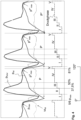
- a characteristic pressure curve p is with several pressure cycles P, P ', P "is exemplary in Fig. 3 shown above in its chronological progression.
- P the pressure fluctuates between a pressure minimum p min at the beginning of the pressure cycle P, initially increases quickly, then goes into a region with a moderate pressure increase and reaches a short-term pressure plateau or pressure maximum p max before the pressure drops rapidly and the next print cycle P ⁇ begins.
- the start of a printing cycle P correlates with an exit of the first roller 5-1 from the hose bed 6 in the outlet area 6-2, at which point a second roller 5-2 is in the in Fig. 2 with the reference symbol ⁇ 0 is located.
- This second roller 5-2 represents the leading role at this moment (and until it exits via the exit area 6-2) and, with further rotation, further reduces the hose volume of the squeeze hose 4 in front of it against a dynamic pressure in the output line 9, which leads to the characteristic increase in pressure.
- this second role the hose bed 6 in the outlet area 6-2, ie approximately at an angular position that is in the Fig. 2 is provided with the reference symbol ⁇ 120 ° , the crushing of the pinch hose 4 is canceled in this area, so that the volume increases almost suddenly up to the subsequent third roller 5-3. This leads to the characteristic pressure drop at the end of a pressure cycle P.
- each of the three rollers 5-1, 5-2, 5-3 will therefore pass through the angular range between ⁇ 0° and ⁇ 120° , designated ⁇ P , and cause a printing cycle P.
- a time course of the pressure phase angle ⁇ i° in is shown Fig. 3 shown below.
- the roller pump 5 is to be regulated to a maximum volume flow Q max without the still permissible pressure limit p limit being exceeded.
- the pressure limit p limit can therefore also be understood as the (maximum) target pressure for the pressure p is .
- Above the limit p limit is in Fig. 3 Additionally, a hazard pressure p hazard pressure is shown, at which irreparable damage to the device or patient occurs. It must therefore be ensured that the hazard pressure p hazard pressure is not exceeded under any circumstances.
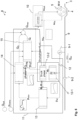
- control device 8 of this exemplary embodiment sees a control according to in Fig. 5 the control scheme shown.
- the control device 8 includes a second control circuit 10 for regulating the Rotational (angular) speed ⁇ of the rotor 7 of the roller pump 5, the pump speed controller (Pump Speed PID controller), which receives the maximum volume flow Q max as a reference variable and converts this into a target rotational (angular) speed ⁇ target or a corresponding rotating field converted to control the roller pump.
- the actual actual rotational (angular) speed ⁇ is fed back as a measured variable and a control deviation between the target and actual rotational (angular) speed is minimized via feedback.
- the second control circuit 10 is preceded by a first control circuit 11, to which a target volume flow Q target and a permissible pressure limit p limit are externally specified as reference variables.
- the feedback variables - unchanged - are the target volume flow Q Soll , the pressure p measured in the output line 9 and the angular speed ⁇ ist of the rotor 7 of the roller pump 5 measured on the roller pump 5 in the first control circuit 11.
- the measurement and feedback of an actual volume flow Q in the output line 9 can be dispensed with.
- the first control circuit 11 is constructed as a discontinuous PID controller, which regulates the controlled variable of the maximum volume flow Q max differently, depending on which pressure phase a pressure cycle is in.
- the first control circuit 11 includes a pressure phase detection 12 with a pressure phase commutation detector 12-1 and a pressure phase switch 12-2, a pressure prediction 13 and a first control component 14 and a second control component 15.
- the printing phase commutation detector 12-1 is used to detect the start of a printing phase. For this purpose, it continuously compares the current pressure p ist with a reference value, namely a temporarily stored pressure maximum p max of a previous printing cycle P, and sets the start of a printing cycle P at the point in time at which a pressure drop in the pressure p is in the output line 9 of more than 1/6 compared to the buffered pressure maximum p max occurs. At this point, one of the rollers 5-1, 5-2, 5-3 of the roller pump 5 is approximately in the in Fig. 2 Angle position marked with ⁇ 0° .
- Phase I is set as the current printing phase.
- the pressure phase switch 12-2 switches or counts up the individual pressure phases II to V.
- the individual pressure phases or the start of the individual pressure phases are determined via the angle ⁇ i° .
- the pressure phase angle ⁇ i ° is in turn detected or approximated - starting from the reference value ⁇ 0 ° - via a temporal integration of the actual angular speed of the roller pump.
- the different printing phases I to V are defined as follows:
- the start of the first printing phase I is defined by a pressure drop of more than 1/6 compared to the pressure maximum of the previous printing cycle.
- the start of the second pressure phase II is set at the point in time at or after a pressure increase occurs safely. This safe pressure increase can be determined by a suitable characteristic number of the pressure curve and can be recognized from this.
- the third pressure phase III corresponds to a first compression phase, the beginning of which is defined at a pressure phase angle of 45° (this corresponds to a phase progression of 37.5% of the complete angular range ⁇ P ).
- a fourth printing phase IV is defined at a printing phase angle of 60° (phase progression of 50%).
- the start of the fifth printing phase V is set at a printing phase angle of 97.2° (phase progress of 81%).
- the individual printing phases I to V of several consecutive printing cycles P, P', P" are the Fig. 4 removable.
- the first control component 14 is activated via the printing phase detection 12 when the current printing cycle P is in the fourth printing phase IV. In all other printing phases (I to III and V), the first control component 14 is deactivated, i.e. set to zero.
- the first control component 14 is the differential element of the PID controller.
- the predicted pressure p future is continuously made available by the pressure forecast 13.
- the forecast pressure represents a forecast for the expected pressure maximum in the current pressure cycle at the defined pressure phase angle.
- the predicted pressure p future is in its time course in Fig. 4 drawn.
- the second control component 15 is the proportional and integral element of the PID controller.
- a correction factor Q I is calculated in it, which is deducted from the target volume flow Q Soll and is calculated using three components ⁇ , ⁇ , ⁇ :
- the maximum pressure p max of each pressure cycle is temporarily stored in a memory in the control device 8. Measuring errors of the pressure p ist can be smoothed out using the mean value filter.
- the power of the roller pump 5 or its rotational speed ⁇ can be regulated and adjusted in advance via the control device 8 designed in this way. Since the maximum volume flow Q max is calculated differently in pressure phases I to III and V than in pressure phase IV, it is a non-continuous control.
- a control response for the case of a disconnected, fluid-impermeable output line 9 is shown in the diagram Fig. 6 with six consecutive printing cycles A to F of measured pressure p is , the prediction pressure p future calculated by the pressure prediction 13 and the associated pressure phases I to V of the individual pressure cycles A to F.
- the absolute pressure maximum p max increases steadily in each pressure cycle: p A max ⁇ p B max ⁇ p C max ⁇ p D max etc.
- the prediction pressure p future exceeds the pressure limit p limit in a fourth pressure phase IV for the first time in pressure cycle F.
- the other excesses of the prediction pressure p future beyond the pressure limit p limit in other phases, for example in pressure cycle D in pressure phase II, are irrelevant, since the control device 8 takes the prediction pressure p future into account only in the pressure phase IV via the control component 14.
- every fourth printing phase IV begins at a printing phase angle of 60° (or a phase progression of 50%)
- the maximum target volume flow Q max in the printing cycle F and thus also the rotational speed ⁇ is with the onset of the printing phase IV in the printing cycle F reduced by the control device 8.
- the throttling of the rotational speed ⁇ is at the beginning of phase IV Fig. 6 easy to see.
- the pressure limit p limit will not be exceeded due to the sufficient lead time between detection of an imminent overshoot of the pressure limit p limit and the occurrence of the pressure maximum p F max ⁇ p limit .
- the control device 8 of the exemplary embodiment can be used Fig. 5 also about an in Fig. 5 Control, not shown, can be added, which increases or decreases the maximum target volume flow Q target depending on the phase progress.
- This control manipulates the reference variable of the target volume flow Q target in such a way that the target volume flow Q target is increased by 30% to an increased target volume flow Q+ at the beginning of a printing cycle and by 30% to a reduced target volume flow towards the end of a printing cycle Q_ is reduced.
- the changed target volume flow Q target is held for a holding period of x-hold.
- the holding period x-hold can correspond to a certain phase progress, such as 25% or the duration of phase I. Due to the opposite adjustment to the increased or reduced target volume flow Q + or Q_, the average target volume flow remains unchanged over a pressure cycle P.
- the corresponding specification of the target volume flow is in Fig. 7A for a printing cycle P with the printing phases I to V. Again Fig. 7A can be seen, the target volume flow Q is suddenly raised to the volume flow Q+ at the beginning of the pressure cycle P and then decreases linearly to the reduced target volume flow Q_.
- the thus changed reference variable of the target volume flow Q Soll which is now variable over time over a pressure cycle P, is fed into the first control circuit 11.
- FIG. 7B a pressure curve is shown for several pressure cycles A to F, whereby the target volume flow Q target in the pressure cycles A to C and the start of the pressure cycle D corresponding to the variable target volume flow Q target Fig. 7A was adjusted and a constant target volume flow was specified in the subsequent pressure cycles.
- the pressure peaks p max of the pressure cycles A, B and C can be reduced compared to the pressure peaks p max of the pressure cycles D, E and F.
- Another effect of this control is that motor power of the peristaltic pump 5 does not have to be suddenly reduced or even braked after the sudden pressure drop at the end of a pressure cycle P in order to keep the volume flow constant. This can save energy and reduce engine noise.
- the angular rotation speed ⁇ is of the peristaltic pump 5 (minus measurement inaccuracies and the influence of the controlled system) has a comparable course to the target volume flow Q Soll . It is therefore possible, instead of the target volume flow, to also increase the angular speed ⁇ target of the peristaltic pump , depending on the pressure phase, to an increased target speed ⁇ + at the beginning of a pressure cycle and / or to reduce it to a reduced target speed ⁇ - towards the end of the printing cycle.
- the invention shown as an example in the exemplary embodiments described enables safer operation of a peristaltic pump with higher media throughput and lower pressure fluctuations.
- control device can also be used for other pumps with cyclically repeating pressure curves, such as diaphragm pumps with an oscillating membrane, piston pumps with pistons moving back and forth, sine pumps or gear pumps.
- the control device is particularly suitable for applications in which pressure relief valves are unsuitable for system reasons because medium is drained through them.
Landscapes
- Engineering & Computer Science (AREA)
- Mechanical Engineering (AREA)
- General Engineering & Computer Science (AREA)
- Health & Medical Sciences (AREA)
- Vascular Medicine (AREA)
- Anesthesiology (AREA)
- Biomedical Technology (AREA)
- Heart & Thoracic Surgery (AREA)
- Hematology (AREA)
- Life Sciences & Earth Sciences (AREA)
- Animal Behavior & Ethology (AREA)
- General Health & Medical Sciences (AREA)
- Public Health (AREA)
- Veterinary Medicine (AREA)
- Infusion, Injection, And Reservoir Apparatuses (AREA)
- Reciprocating Pumps (AREA)
Abstract
Die Erfindung betrifft u.a. eine Regeleinrichtung (8) für eine Peristaltikpumpe (5), die ein Medium in pulsierenden Druckzyklen fördert, wobei die Regeleinrichtung (8) eine Geschwindigkeit der Peristaltikpumpe (5) so regelt, dass ein maximaler Volumenstrom (Q<sub>max</sub>) erreicht wird, ohne dabei eine Druckgrenze (p<sub>Grenz</sub>) in der Ausgabeleitung (9) zu überschreiten. Eine Aufgabe ist es, den tatsächlichen Druck in der Ausgabeleitung (9) möglichst nahe an der Druckgrenze (p<sub>Grenz</sub>) zu führen bzw. den Abstand hierzu zu minimieren. Zur Lösung wird vorgeschlagen, für jeden Druckzyklus (P) ein Vorhersagedruck (p<sub>futur</sub>) für einen zu erwartenden Maximaldruck innerhalb des Druckzyklus (P) auf Basis mindestens des Drucks (p<sub>ist</sub>) in der Ausgabeleitung (9) zu berechnen und mithilfe des Vorhersagedrucks den maximalen Volumenstrom (Q<sub>max</sub>) so zu begrenzen, dass der Druck (p<sub>ist</sub>) in der Ausgabeleitung (9) die Druckgrenze (p<sub>Grenz</sub>) in dem Druckzyklus (P) nicht überschreitet. Die Erfindung betrifft auch artverwandte Aspekte.The invention relates, among other things, to a control device (8) for a peristaltic pump (5), which conveys a medium in pulsating pressure cycles, the control device (8) regulating a speed of the peristaltic pump (5) in such a way that a maximum volume flow (Q<sub>max </sub>) is achieved without exceeding a pressure limit (p<sub>limit</sub>) in the output line (9). One task is to bring the actual pressure in the output line (9) as close as possible to the pressure limit (p<sub>limit</sub>) or to minimize the distance thereto. As a solution, it is proposed to create a prediction pressure (p<sub>futur</sub>) for each pressure cycle (P) for an expected maximum pressure within the pressure cycle (P) based on at least the pressure (p<sub>act</sub>). ) in the output line (9) and using the forecast pressure to limit the maximum volume flow (Q<sub>max</sub>) so that the pressure (p<sub>act</sub>) in the output line (9 ) does not exceed the pressure limit (p<sub>Limit</sub>) in the printing cycle (P). The invention also relates to related aspects.
Description
Die Erfindung betrifft eine Regeleinrichtung für eine Peristaltikpumpe nach dem Oberbegriff des Anspruchs 1, eine Peristaltikpumpe mit einer solchen Regeleinrichtung, ein Injektionsgerät mit einer solchen Peristaltikpumpe und ein Verfahren zur Steuerung einer Peristaltikpumpe.The invention relates to a control device for a peristaltic pump according to the preamble of
Injektionsgeräte sind medizinische Geräte, mittels derer flüssige Injektionsmittel (Medium) über eine Pumpvorrichtung kontrolliert in einen menschlichen oder tierischen Körper eingebracht werden kann. Bei dem Injektionsmittel kann es sich bspw. um ein Kontrastmittel zur Erhöhung des Kontrasts in einem bildgebenden Verfahren, wie der Computertomographie oder der Magnetresonanztomographie, handeln. Neben einer Kontrolle des Injektionsvolumens sowie einer Durchflussrate (Volumenstrom) des Injektionsmittels ist es notwendig, den Druck in einer Ausgangsleitung zu überwachen, da zu hohe Drücke einerseits schädlich für den Körper sein und/oder das Injektionsgerät schädigen können. Aus diesem Grund sehen bekannte Injektionsgeräte Steuerungen oder Regelungen vor, die das Injektionsgerät bzw. dessen Pumpvorrichtung bei Überschreitung einer noch zulässigen Druckgrenze (maximaler Soll-Druck), der unterhalb eines definierten Gefährdungsdrucks liegt, abschalten. Gerade bei zyklisch oszillierenden Druckverläufen, die z.B. bei Axialkolben- oder Rollenpumpen vorliegen, können Druckmaxima auftreten, die nur kurzzeitig und geringfügig über dem Druckgrenzwert liegen und deshalb zu einem unnötigen Abschalten der Pumpvorrichtung bzw. einem Abbruch des Injektionsvorgangs führen. Dies verlängert den Injektionsvorgang und erhöht unnötig das insgesamt injizierte Volumen an Injektionsmittels.Injection devices are medical devices with which liquid injection agents (medium) can be introduced into a human or animal body in a controlled manner using a pump device. The injection agent can be, for example, a contrast agent for increasing the contrast in an imaging method, such as computer tomography or magnetic resonance tomography. In addition to checking the injection volume and the flow rate (volume flow) of the injection agent, it is necessary to monitor the pressure in an output line, as pressures that are too high can be harmful to the body and/or damage the injection device. For this reason, known injection devices provide controls or regulations that switch off the injection device or its pumping device when a permissible pressure limit (maximum target pressure), which is below a defined dangerous pressure, is exceeded. Especially with cyclically oscillating pressure curves, which are present in axial piston or roller pumps, for example, pressure maxima can occur that are only briefly and slightly above the pressure limit and therefore lead to the pump device being switched off unnecessarily or the injection process being aborted. This prolongs the injection process and unnecessarily increases the total injected volume of injectable.
Zur Vermeidung von vorschnellen Abbrüchen eines Injektionsvorgangs wird in der
Ebenso ist es aus der
Nachteilig bei den aus dem Stand der Technik bekannten Regelungsverfahren für Injektionsgeräte ist, dass große Sicherheitsintervalle eingehalten werden müssen - d.h. die Druckgrenze muss deutlich unterhalb des Gefährdungsdrucks liegen - so dass eine ausreichende Reaktionszeit besteht, um die Pumpvorrichtung bei Überschreiten der Druckgrenze herunterregeln bzw. abschalten zu können.The disadvantage of the control methods for injection devices known from the prior art is that large safety intervals must be maintained - i.e. the pressure limit must be well below the dangerous pressure - so that there is sufficient reaction time to regulate or switch off the pump device when the pressure limit is exceeded can.
Vor diesem Hintergrund ist es Aufgabe der Erfindung, eine verbesserte Regeleinrichtung für eine Peristaltikpumpe mit einem oszillierenden Druckverlauf (Druckpulsation), eine Peristaltikpumpe mit einer solchen Regeleinrichtung, ein Injektionsgerät mit einer solchen Peristaltikpumpe sowie ein Regelungsverfahren anzugeben, bei denen Sicherheitsintervalle reduziert und eine vorgegebene Druckgrenze näher an einen Gefährdungsdruck herangeführt werden können, ohne ein Schädigungsrisiko für den Patienten und/oder das Material des Injektionsgeräts zu erhöhen. Gleichzeitig sollen Druckpulsationen verringert werden.Against this background, it is the object of the invention to provide an improved control device for a peristaltic pump with an oscillating pressure curve (pressure pulsation), a peristaltic pump with such a control device, an injection device with such a peristaltic pump and a control method in which safety intervals are reduced and a predetermined pressure limit is closer can be brought to a dangerous pressure without increasing the risk of harm to the patient and/or the material of the injection device. At the same time, pressure pulsations should be reduced.
Diese Aufgabe wird u.a. gelöst durch die Regeleinrichtung des Anspruchs 1, die Peristaltikpumpe gemäß Anspruch 12, einem Injektionsgerät nach Anspruch 14 sowie einem Regelungsverfahren nach Anspruch 15.This object is achieved, among other things, by the control device of
Die erfindungsgemäße Regeleinrichtung dient zur Regelung einer Peristaltikpumpe mit einem Quetschschlauch und sich zyklisch bewegenden Förderelementen zur Förderung eines in dem Quetschschlauch geführten Mediums während eines Fördervorgangs mit einem kontrollierten Volumenstrom in eine mit dem Quetschschlauch verbundene Ausgabeleitung. Dabei komprimieren die Förderelemente den Quetschschlauch zyklisch, so dass sich in der Ausgabeleitung ein Druck mit einem Druckverlauf einstellt, der zyklisch sich wiederholende Druckzyklen aufweist. Jeder Druckzyklus kann so definiert werden, dass er sich bspw. von einem Druckminimum über einen Druckanstieg zu einem Druckmaximum erstreckt und anschließend wieder auf ein Druckminimum eines darauffolgenden Druckzyklus abfällt. Die erfindungsgemäße Regeleinrichtung regelt dabei eine Geschwindigkeit der Peristaltikpumpe - im Falle einer Rollenpumpe kann es sich um eine Winkelgeschwindigkeit eines Förderelements handeln - so, dass ein maximaler Volumenstrom erreicht wird, ohne dass dabei eine Druckgrenze in der Ausgabeleitung überschritten wird. Bei der Druckgrenze kann es sich um einen gewünschten, noch zulässigen Soll-Druck handeln. Die Regeleinrichtung weist hierzu zumindest einen ersten Regelkreis zur Regelung des maximalen Volumenstroms auf. Dieser erhält als extern vorgegebene Führungsgrößen einen Soll-Volumenstrom und die Druckgrenze. Die Regeleinrichtung ist dabei eingerichtet, ein Regelverfahren auszuführen, bei dem für jeden Druckzyklus ein Vorhersagedruck für einen zu erwartenden Maximaldruck innerhalb des Druckzyklus auf Basis mindestens des Drucks in der Ausgabeleitung berechnet wird und der maximale Volumenstrom unter Berücksichtigung des Vorhersagedrucks so begrenzt wird, dass der Druck in der Ausgabeleitung die Druckgrenze in dem Druckzyklus nicht überschreitet.The control device according to the invention is used to control a peristaltic pump with a squeeze hose and cyclically moving conveying elements for conveying a medium guided in the squeeze hose during a conveying process with a controlled volume flow into an output line connected to the squeeze hose. The conveying elements compress the squeeze tube cyclically, so that a pressure is established in the output line with a pressure curve that has cyclically repeating pressure cycles. Each printing cycle can be defined in such a way that it extends, for example, from a pressure minimum through a pressure increase to a pressure maximum and then drops again to a pressure minimum of a subsequent printing cycle. The control device according to the invention regulates a speed of the peristaltic pump - in the case of a roller pump, this can be an angular speed of a conveying element act - in such a way that a maximum volume flow is achieved without a pressure limit in the output line being exceeded. The pressure limit can be a desired, still permissible target pressure. For this purpose, the control device has at least a first control circuit for regulating the maximum volume flow. This receives a target volume flow and the pressure limit as externally specified reference variables. The control device is set up to carry out a control method in which a prediction pressure for an expected maximum pressure within the pressure cycle is calculated for each pressure cycle based on at least the pressure in the output line and the maximum volume flow is limited, taking the prediction pressure into account, so that the pressure in the output line does not exceed the pressure limit in the printing cycle.
Zweckmäßig erfasst der erste Regelkreis den aktuellen Druck in der Ausgabeleitung als eine Rückführungsgröße, anhand derer ein Regelteil des Regelkreises den maximalen Volumenstrom vorausschauend regelt.The first control loop expediently records the current pressure in the output line as a feedback variable, based on which a control part of the control loop controls the maximum volume flow in a predictive manner.
Durch eine vorausschauende Regelung kann die Geschwindigkeit der Peristaltikpumpe, insb. der Förderelemente der Peristaltikpumpe, bei drohender Überschreitung der Druckgrenze frühzeitig und proaktiv angepasst und insb. reduziert werden. Da durch die Druckvorhersage Reaktionszeiträume verlängert werden, steigen Sicherheitsreserven. Noch zulässige Druckgrenzen können dann näher an kritische Druckwerte, wie z.B. einen Gefährdungsdruck, herangeführt werden, was wiederum höhere Volumenströme und damit z.B. eine Verkürzung einer Injektionsdauer für ein bestimmtes Injektionsvolumen bedeutet. Da bei einer vorausschauenden Regelung die Bedeutung einer reaktionsschnellen Mechanik an Bedeutung verliert, können außerdem verstärkt reaktionsträge Komponenten für die Peristaltikpumpe genutzt werden, wodurch die Herstellung der Peristaltikpumpe billiger wird. Eine Kalibrierung des Regelverfahrens ist bei geeigneter Auslegung der Regeleinrichtung nicht notwendig.Through predictive control, the speed of the peristaltic pump, especially the conveying elements of the peristaltic pump, can be adjusted early and proactively and, in particular, reduced if the pressure limit is threatened to be exceeded. Since reaction times are extended by the pressure forecast, safety reserves increase. Pressure limits that are still permissible can then be brought closer to critical pressure values, such as a danger pressure, which in turn means higher volume flows and thus, for example, a shortening of the injection duration for a specific injection volume. Since the importance of fast-reacting mechanics becomes less important with predictive control, more inert components can also be used for the peristaltic pump, which makes the production of the peristaltic pump cheaper. Calibration of the control process is not necessary if the control device is designed appropriately.
In einer bevorzugten Ausführung der Erfindung umfasst der erste Regelkreis eine Druckphasenerkennung, durch die das Ende eines vorangehenden Druckzyklus und der Beginn eines darauffolgenden Druckzyklus erkannt wird. Die Erkennung kann anhand einer charakteristischen Größe des Druckverlaufs in der Ausgabeleitung, insbesondere einem definierten Druckabfall gegenüber einem Druckmaximum des vorhergehenden Druckzyklus, erfolgen. Der Beginn eines Druckzyklus kann bspw. zu dem Zeitpunkt definiert sein, bei dem ein Druckabfall gegenüber dem (absoluten) Druckmaximum des vorhergehenden Druckzyklus um mehr als einen bestimmten relativen Betrag, bspw. etwa um mindestens 1/6, ¼ oder 1/3 oder - unabhängig von dem vorhergehenden Druckmaximum -um einen absoluten Betrag, z.B. mindestens 2bar, auftritt. Der Druckabfall wird dabei vorteilhaft so groß gewählt, dass dieser Druckabfall nur einmal gegen Ende eines Druckzyklus auftritt. Das Auftreten dieses Druckabfalls ist dann hinreichend robust, um den Beginn eines darauffolgenden Druckzyklus anzuzeigen. Sollte ein typischer Druckzyklus größere Druckschwankungen aufweisen, können ersatzweise größere Druckabfälle und/oder inkrementelle Zähler verwendet werden, die die Anzahl von Druckabfällen um einen bestimmten Mindestbetrag zählen, um so den Beginn eines nachfolgenden Druckzyklus zu erkennen.In a preferred embodiment of the invention, the first control circuit includes a printing phase detection, through which the end of a previous printing cycle and the beginning of a subsequent printing cycle are recognized. The detection can take place based on a characteristic size of the pressure curve in the output line, in particular a defined pressure drop compared to a pressure maximum of the previous printing cycle. The start of a printing cycle can, for example, be defined at the point in time a pressure drop compared to the (absolute) pressure maximum of the previous pressure cycle by more than a certain relative amount, for example by at least 1/6, ¼ or 1/3 or - regardless of the previous pressure maximum - by an absolute amount, for example at least 2 bar, occurs. The pressure drop is advantageously chosen to be so large that this pressure drop only occurs once towards the end of a printing cycle. The occurrence of this pressure drop is then sufficiently robust to indicate the start of a subsequent pressure cycle. Should a typical printing cycle have larger pressure fluctuations, larger pressure drops and/or incremental counters can be used as an alternative, which count the number of pressure drops by a certain minimum amount in order to detect the start of a subsequent printing cycle.
Zu Beginn jedes Druckzyklus wird die Regelung des maximalen Volumenstroms neu eingeleitet, und insb. zwischengespeicherte Werte, wie ein zwischengespeichertes Druckmaximum des vorhergehenden Druckzyklus, aktualisiert.At the beginning of each printing cycle, the regulation of the maximum volume flow is initiated again, and in particular buffered values, such as a buffered pressure maximum of the previous printing cycle, are updated.
Für eine weitergehende Verbesserung der Regeleinrichtung ist vorteilhaft vorgesehen, dass jeder Druckzyklus anhand vordefinierter Charakteristika in sukzessive aufeinanderfolgende Druckphasen eingeteilt ist und die Druckphasenerkennung den Beginn der einzelnen Druckphasen erkennt, wobei der Vorhersagedruck zur Regelung des maximalen Volumenstroms in dem ersten Regelkreis nur in bestimmten Druckphasen verwendet und in anderen Druckphasen ignoriert bzw. nicht verwendet wird. Die Regelung ist damit unstetig.For a further improvement of the control device, it is advantageously provided that each pressure cycle is divided into successive pressure phases based on predefined characteristics and the pressure phase detection detects the beginning of the individual pressure phases, the prediction pressure being used to control the maximum volume flow in the first control loop only in certain pressure phases and ignored or not used in other printing phases. The regulation is therefore discontinuous.
Ein Vorteil einer solchen druckphasenabhängigen Regelung liegt darin, dass die Druckvorhersage genau in den Druckphasen eingesetzt werden kann, bei denen die Entwicklung des Drucks in der Ausgabeleitung dynamisch ist und eine Überschreitung der Druckgrenze vergleichsweise plötzlich eintreten kann, so dass in diesen Druckphasen der maximale Volumenstrom konservativ geregelt wird, während er in anderen Druckphasen aggressiver geregelt werden kann, da ein plötzliches Überschreiten der Druckgrenze in diesen anderen Druckphasen nicht zu erwarten ist. Ein weiterer Vorteil ist, dass für unterschiedliche Druckphasen unterschiedliche Regelungen mit z.B. Zuschaltung oder Abschaltung zusätzlicher Regelkreise, die dem ersten Regelkreis überlagert werden und/oder der Veränderung der Regelparameter des ersten Regelkreises, etwa darin verwendeter Verstärkungsfaktoren o.ä., realisiert werden können.An advantage of such a pressure phase-dependent control is that the pressure prediction can be used precisely in the pressure phases in which the development of the pressure in the output line is dynamic and the pressure limit can be exceeded comparatively suddenly, so that the maximum volume flow is conservative in these pressure phases is regulated, while it can be regulated more aggressively in other pressure phases, since a sudden exceeding of the pressure limit is not to be expected in these other pressure phases. A further advantage is that different controls can be implemented for different pressure phases, for example by switching on or switching off additional control loops that are superimposed on the first control loop and/or by changing the control parameters of the first control loop, such as the gain factors used therein or the like.
Bei den vorgenannten, vordefinierten Charakteristika kann es sich um absolute oder relative Druckänderungen und/oder um eine absolute oder relative Druckänderungsrate des Drucks in der Ausgabeleitung handeln. Bei den vordefinierten Charakteristika muss es sich nicht zwingend um punktuelle Werte handeln. Es ist bspw. möglich, gleitende Durchschnitte über bestimmte Zeitspannen, wie etwa 0,1, 0,2 oder 0,5 Sekunden, zu wählen.The aforementioned predefined characteristics may be absolute or relative pressure changes and/or an absolute or relative pressure change rate of the pressure in the output line. The predefined characteristics do not necessarily have to be point values. For example, it is possible to choose moving averages over specific time periods, such as 0.1, 0.2 or 0.5 seconds.
Die Erkennung der einzelnen Druckphasen durch die Druckphasenerkennung kann anhand der vordefinierten Charakteristika erfolgen. Alternativ können einzelne Druckphasen jedoch auch anhand einer Position der Förderelemente der Peristaltikpumpe durch die Druckphasenerkennung erkannt werden, da die Positionen der Förderelemente - wie weiter unten noch näher erläutert -mit den einzelnen Druckphasen korrelieren. Es ist ebenso möglich, die Erkennung anhand vordefinierter Charakteristika sowie einer Positionsbestimmung der Förderelemente für die Druckphasenerkennung zu kombinieren, sei es zeitgleich, um die Druckphasenerkennung einzelner Druckphasen redundant auszugestalten oder sei es, um einzelne Druckphasen anhand der definierten Charakteristika und andere Druckphasen anhand der Position der Förderelemente zu bestimmen. Bevorzugt ist die Druckphasenerkennung zur Erhöhung der Zuverlässigkeit redundant ausgeführt. Hierdurch können eine Fehleranfälligkeit und insb. Anforderungen an die Ausfallsicherheit einzelner Komponenten, und dadurch Bauteilkosten, reduziert werden.The recognition of the individual pressure phases by the pressure phase detection can be done based on the predefined characteristics. Alternatively, however, individual pressure phases can also be recognized based on a position of the conveying elements of the peristaltic pump through the pressure phase detection, since the positions of the conveying elements - as explained in more detail below - correlate with the individual pressure phases. It is also possible to combine the detection based on predefined characteristics and a position determination of the conveying elements for the printing phase detection, be it at the same time in order to make the printing phase detection of individual printing phases redundant or be it in order to detect individual printing phases based on the defined characteristics and other printing phases based on the position of the Determine conveying elements. The pressure phase detection is preferably designed redundantly to increase reliability. This makes it possible to reduce susceptibility to errors and, in particular, requirements for the reliability of individual components, and thus component costs.
In einer Ausführungsvariante der Erfindung ist der Druckzyklus durch fünf aufeinanderfolgende Druckphasen gekennzeichnet, wobei eine erste Druckphase durch einen schnellen Druckverlust, eine zweite Druckphase durch einen schnellen Druckanstieg, eine dritte Druckphase durch einen flachen Druckanstieg, eine vierte Druckphase durch einen moderaten Druckanstieg und eine fünfte Druckphase durch ein Druckplateau mit im Wesentlichen konstantem Druck gekennzeichnet ist, und jede Druckphase durch die Druckphasenerkennung erkannt wird. Eine derartige Einteilung eines Druckzyklus ist eine gute Annäherung für Druckzyklen in Injektionsgeräten zur intravenösen Injektion von z.B. Kontrastmitteln. Für die einzelnen Druckphasen sind dabei die statischen und dynamischen Druckwiderstände in der Ausgabeleitung (und den sich anschließenden Leitungen) verantwortlich, die sich insb. durch sich öffnende und schließende Rückschlagventile, Drosseln, den Massenträgheiten des zu fördernden Mediums und anderen Einflüssen ergeben. Für andere Anwendungen können die Druckphasen auch anders als in obigem Beispiel definiert werden.In an embodiment variant of the invention, the printing cycle is characterized by five successive printing phases, with a first printing phase characterized by a rapid pressure loss, a second printing phase characterized by a rapid pressure increase, a third printing phase characterized by a flat pressure increase, a fourth printing phase characterized by a moderate pressure increase and a fifth printing phase is characterized by a pressure plateau with essentially constant pressure, and each pressure phase is recognized by the pressure phase detection. Such a division of a pressure cycle is a good approximation for pressure cycles in injection devices for intravenous injection of, for example, contrast agents. The static and dynamic pressure resistances in the output line (and the adjoining lines) are responsible for the individual pressure phases, which arise in particular from opening and closing check valves, throttles, the mass inertia of the medium to be pumped and other influences. For other applications, the printing phases can also be defined differently than in the example above.
Bevorzugt ist, wenn im ersten Regelkreis der Vorhersagedruck zur Regelung des maximalen Volumenstroms nur in der vierten Druckphase, d.h. der Druckphase vor dem Druckplateau mit dem (absoluten) Druckmaximum innerhalb des Druckzyklus, verwendet wird. Die vierte Druckphase ist vorteilhaft in einem Bereich definiert, der sich von etwa 50% bis etwa 80% eines Phasenfortschritts des Druckzyklus bewegt. Unter Phasenfortschritt ist der Druckzyklus in zeitlicher Auflösung zu verstehen, d.h. der Druckzyklus beginnt bei 0% Phasenfortschritt - dies entspricht z.B. einem Druckminimum - und endet bei 100% - dies entspricht dann dem Druckminimum des darauffolgenden Druckzyklus. Da der Vorhersagedruck in der vierten Druckphase zur Berechnung des maximalen Volumenstroms auf den ersten Regelkreis 'aufgeschaltet' wird, und ansonsten ,abgeschaltet` ist, handelt es sich um einen unstetigen Regler. Durch eine derartige Beschränkung der Verwendung des Vorhersagedrucks kann auf eine aufwendige Berechnung des Vorhersagedrucks in den anderen Druckphasen verzichtet werden.It is preferred if in the first control loop the prediction pressure for controlling the maximum volume flow is only used in the fourth pressure phase, i.e. the pressure phase before the pressure plateau with the (absolute) pressure maximum within the pressure cycle. The fourth printing phase is advantageously defined in a range that ranges from approximately 50% to approximately 80% of a phase progression of the printing cycle. Phase progression is understood to mean the printing cycle in time resolution, i.e. the printing cycle begins at 0% phase progression - this corresponds, for example, to a pressure minimum - and ends at 100% - this then corresponds to the pressure minimum of the subsequent printing cycle. Since the forecast pressure is 'connected' to the first control loop in the fourth pressure phase to calculate the maximum volume flow, and is otherwise 'switched off', it is a discontinuous controller. By limiting the use of the prediction pressure in this way, a complex calculation of the prediction pressure in the other printing phases can be dispensed with.
Der Vorhersagedruck kann in einer einfachen und daher vorzugswürdigen Variante über eine lineare Extrapolation des aktuellen Druckanstiegs in der Ausgabeleitung zu einem bestimmten (rechnerischen) Phasenfortschritt, der bevorzugt im Bereich von 80% bis 95% des gesamten Phasenfortschritts liegt und z.B. bei 80%, 90% oder 95% des gesamten Phasenfortschritts und insb. bei 87% des gesamten Phasenfortschritts liegen kann, bestimmt werden. Bei Verwendung des Vorhersagedrucks nur in der vierten Druckphase ist die Vorhersagegenauigkeit einer linearen Extrapolation selbst bei einem stark oszillierenden Druckverlauf eines Druckzyklus hinreichend genau. Auch andere Berechnungsverfahren zur Bestimmung des Vorhersagedrucks, insb. eine Extrapolation auf Basis einer Zeitreihe, sind möglich.In a simple and therefore preferable variant, the prediction pressure can be achieved via a linear extrapolation of the current pressure increase in the output line to a specific (calculated) phase progress, which is preferably in the range of 80% to 95% of the total phase progress and, for example, at 80%, 90% or 95% of the total phase progress and in particular 87% of the total phase progress can be determined. When using the prediction pressure only in the fourth printing phase, the prediction accuracy of a linear extrapolation is sufficiently accurate even with a strongly oscillating pressure curve of a pressure cycle. Other calculation methods for determining the forecast pressure, especially extrapolation based on a time series, are also possible.
Der bestimmte (rechnerische) Phasenfortschritt, der zur Bestimmung des Vorhersagedrucks verwendet wird, ist dabei zweckmäßig fest gewählt und liegt z.B. bei konstant 87% des gesamten Phasenfortschritts. Dieser bestimmte Phasenfortschritt kann - muss jedoch nicht - mit dem realen Phasenfortschritt übereinstimmen, bei dem reale Druckmaxima in den Druckzyklen auftreten. Tatsächliche Druckmaxima können also bei tatsächlichen Phasenfortschritten auftreten, die vor oder auch hinter dem bestimmten (rechnerischen) Phasenfortschritt von im Beispiel 87% des gesamten Phasenfortschritts liegen.The specific (calculated) phase progress that is used to determine the forecast pressure is expediently chosen to be fixed and is, for example, a constant 87% of the total phase progress. This particular phase progression can - but does not have to - correspond to the real phase progression at which real pressure maxima occur in the pressure cycles. Actual pressure maxima can therefore occur at actual phase progressions that lie before or behind the specific (calculated) phase progression of, in the example, 87% of the total phase progression.
Der bestimmte Phasenfortschritt ist bevorzugt rechnerisch so gewählt und eingestellt, dass Vorhersagedrücke erzielt werden, die möglichst genau die tatsächlichen Druckmaxima von aufeinanderfolgenden Druckzyklen wiedergeben. Der bestimmte (rechnerische) Phasenfortschritt, zu dem der Vorhersagedruck extrapoliert wird, kann dabei verschoben zu dem realen Phasenfortschritt sein, bei dem ein reales Druckmaximum auftritt, wenn sich hierdurch bessere Vorhersagedrücke ergeben.The specific phase progress is preferably selected and set mathematically so that prediction pressures are achieved that correspond as accurately as possible to the actual pressure maxima successive print cycles. The specific (computational) phase progression to which the forecast pressure is extrapolated can be shifted to the real phase progression at which a real pressure maximum occurs, if this results in better forecast pressures.
In einer konkretisierten Anwendung der Erfindung regelt die Regeleinrichtung eine Rollenpumpe. Rollenpumpen haben den Vorteil nicht auftretender Richtungswechsel, weshalb sich Rollenpumpen besonders gut für eine genaue Dosierung von Injektionsboli in Injektionsgeräten eignen. Da das geförderte Medium bei Rollenpumpen in einem Quetschschlauch gefördert wird, findet in Rollenpumpen außerdem kein unmittelbarer Kontakt zwischen dem geförderten Medium und der Pumpe statt, was aus hygienischen Gründen vorteilhaft ist. Weiterhin kann der Quetschschlauch einfach ausgetauscht werden.In a specific application of the invention, the control device controls a roller pump. Roller pumps have the advantage that there are no changes in direction, which is why roller pumps are particularly suitable for precise dosing of injection boluses in injection devices. Since the medium conveyed in roller pumps is conveyed in a squeeze hose, there is no direct contact between the medium conveyed and the pump in roller pumps, which is advantageous for hygienic reasons. Furthermore, the squeeze hose can be easily replaced.
Gegenstand der Erfindung ist daher auch eine Rollenpumpe mit einem drehbaren Rotor, einer Mehrzahl von Förderelementen zum Quetschen eines Quetschschlauchs, die als an dem Rotor angeordnete Rollen (Quetschrollen) ausgebildet sind, wobei der Quetschschlauch entlang eines Schlauchbetts mit einem Einlaufbereich und einem Auslaufbereich gelagert ist und die Förderelemente bei Drehung des Rotors nacheinander jeweils einen Abschnitt des Quetschschlauchs beim Eintreten der Förderelemente in das Schlauchbett auf Höhe des Einlaufbereichs und bis zum Austreten der Förderelemente aus dem Schlauchbett auf Höhe des Auslaufbereichs fluiddicht quetschen und dadurch ein in dem Quetschschlauch befindliches Medium in Drehrichtung entgegen einem Staudruck in einer mit dem Quetschschlauch verbundenen Ausgabeleitung in die Ausgabeleitung fördern, wobei die Rollenpumpe eine erfindungsgemäße Regeleinrichtung enthält.The invention therefore also relates to a roller pump with a rotatable rotor, a plurality of conveying elements for squeezing a squeeze hose, which are designed as rollers (squeeze rollers) arranged on the rotor, the squeeze hose being mounted along a hose bed with an inlet area and an outlet area and When the rotor rotates, the conveying elements successively squeeze a section of the squeeze hose in a fluid-tight manner when the conveying elements enter the hose bed at the level of the inlet area and until the conveying elements exit the hose bed at the level of the outlet area and thereby a medium located in the squeeze hose in the direction of rotation in the opposite direction Promote dynamic pressure in an output line connected to the squeeze hose into the output line, the roller pump containing a control device according to the invention.
Dabei wird jeweils ein vor dem Auslaufbereich befindliches Volumen des Quetschschlauchs von einem maximalen Volumen auf ein minimales Volumen komprimiert, solange bis ein Förderelement auf Höhe des Auslaufbereichs aus dem Schlauchbett austritt, den durch dieses Förderelement gequetschten Abschnitt des Quetschlauchs freigibt und damit das vor dem Auslaufbereich befindliche Volumen des Quetschschlauchs von dem minimalen Volumen auf das maximale Volumen vergrößert. Die Volumenreduktion und Volumenvergrößerung des vor dem Auslaufbereich befindlichen Volumens stellen gemeinsam einen vollständigen Druckzyklus dar.In each case, a volume of the squeeze tube located in front of the outlet area is compressed from a maximum volume to a minimum volume until a conveying element emerges from the hose bed at the level of the outlet area, releasing the section of the squeeze tube squeezed by this conveying element and thus that located in front of the outlet area Volume of the squeeze tube increased from the minimum volume to the maximum volume. The volume reduction and volume increase of the volume in front of the outlet area together represent a complete printing cycle.
Die Rollenpumpe weist ferner n vorzugsweise radial gleichverteilte Förderelemente auf, so dass die Rollenpumpe bei einer vollständigen Drehung des Rotors um 360° n Pumpenhübe mit n Druckzyklen ausführt. Die Anzahl der Rollenelemente beträgt z.B. drei.The roller pump also has n preferably radially uniformly distributed conveying elements, so that the roller pump carries out n pump strokes with n pressure cycles when the rotor rotates completely through 360°. The number of role elements is, for example, three.
Da jedes Förderelement nur in einem bestimmten Winkelabschnitt, nämlich in dem Winkelabschnitt in dem das Förderelement die "führende" Rolle in Bezug auf den Auslaufbereich bzw. die Ausgabeleitung darstellt, an einem Druckzyklus beteiligt ist, korreliert in diesem Winkelabschnitt die Winkelposition des Förderelements mit dem Phasenfortschritt des Druckzyklus. Dadurch korrelieren auch einzelne Winkelbereiche der Winkelposition der Förderelemente innerhalb des Winkelabschnitts mit einzelnen Druckphasen eines Druckzyklus.Since each conveying element is only involved in a printing cycle in a certain angular section, namely in the angular section in which the conveying element represents the "leading" role in relation to the outlet area or the output line, the angular position of the conveying element correlates with the phase progress in this angular section of the printing cycle. As a result, individual angular ranges of the angular position of the conveying elements within the angular section also correlate with individual printing phases of a printing cycle.
Dies ermöglicht vorteilhaft eine Bestimmung der Druckphase anhand der Winkelposition eines der Förderelemente, insb. eines 'fiihrenden' Förderelements. Anstelle einer fehleranfälligen Druckphasenerkennung über vordefinierte Charakteristika, die unzuverlässig sein können, ist es zweckmäßig, wenn die Druckphasenerkennung der Regeleinrichtung den Beginn mindestens einer Druckphase eines Druckzyklus über eine Winkelposition eines Förderelements bestimmt.This advantageously enables the pressure phase to be determined based on the angular position of one of the conveying elements, in particular a 'leading' conveying element. Instead of error-prone printing phase detection using predefined characteristics that can be unreliable, it is expedient if the printing phase detection of the control device determines the start of at least one printing phase of a printing cycle via an angular position of a conveying element.
Um auf Positionssensoren zur Ermittlung der Winkelposition der Förderelemente verzichten zu können, wird die Winkelposition zweckmäßig indirekt z.B. über die zeitliche Integration der Winkelgeschwindigkeit der Förderelemente bzw. des Rotors der Rollenpumpe ermittelt. Die Winkelgeschwindigkeit des Rotors steht üblicherweise unmittelbar über ein Steuergerät der Rollenpumpe zur Verfügung. Wie weiter oben dargestellt, kann über einen Druckabfall um einen Mindestbetrag eine absolute Winkelposition des führenden Förderelements angenähert werden.In order to be able to dispense with position sensors for determining the angular position of the conveying elements, the angular position is expediently determined indirectly, for example via the temporal integration of the angular velocity of the conveying elements or the rotor of the roller pump. The angular velocity of the rotor is usually available directly via a roller pump control unit. As shown above, an absolute angular position of the leading conveying element can be approximated via a pressure drop by a minimum amount.
In einer weiterführenden Ausgestaltung der Erfindung umfasst der erste Regelkreis einen Mittelwert-Filter, das den maximalen Volumenstrom in Abhängigkeit eines in der Regeleinrichtung zwischengespeicherten Maximaldrucks eines dem aktuellen Druckzyklus unmittelbar vorhergehenden Druckzyklus anpasst. Hierdurch können Fehler in der Messung des Drucks in der Ausgabeleitung ausgeglichen werden. Außerdem kann durch den Mittelwert-Filter das Schwingungsverhalten des Regelkreises gedämpft und insb. ein Überschwingen der Regelgröße verhindert oder zumindest reduziert werden. Zweckmäßig wird hierzu der vorhergehende, gemessene Maximaldruck als Verhältnis von dem gemessenen Maximaldruck zu der Druckgrenze (Soll-Druck) in den ersten Regelkreis zurückgeführt und hierauf basierend ein neuer Soll-Volumenstrom eingestellt. Eine Abweichung zwischen dem tatsächlich auftretenden Maximaldruck und der Druckgrenze (Soll-Druck) kann hierdurch mit jedem Zyklus verringert werden.In a further embodiment of the invention, the first control circuit comprises a mean value filter which adapts the maximum volume flow depending on a maximum pressure temporarily stored in the control device of a pressure cycle immediately preceding the current pressure cycle. This allows errors in the measurement of the pressure in the output line to be compensated for. In addition, the mean value filter can dampen the oscillation behavior of the control loop and, in particular, prevent or at least reduce overshoot of the controlled variable. For this purpose, the previous measured maximum pressure is used as a ratio of the measured maximum pressure to the pressure limit (target pressure) is returned to the first control loop and a new target volume flow is set based on this. A deviation between the actual maximum pressure and the pressure limit (target pressure) can be reduced with each cycle.
Vorteilhaft ist der erste Regelkreis ein PID-Regler mit einem Proportional-Glied, einem Integral-Glied und einem Differential-Glied. Durch einen PID-Regler ist eine schnelle und genaue Annäherung der Regelgröße an die Führungsgrößen möglich.The first control circuit is advantageously a PID controller with a proportional element, an integral element and a differential element. A PID controller enables the controlled variable to approach the reference variables quickly and accurately.
In dem Differential-Glied wird vorzugsweise der Vorhersagedruck zur Regelung des maximalen Volumenstroms verarbeitet. In dem Differential-Glied können jedoch auch weitere Rückführungsgrößen, z.B. eine Änderungsrate einer Drehgeschwindigkeit eines Rotors einer Peristaltikpumpe und/oder eine Änderungsrate des Volumenstroms berücksichtigt werden.The prediction pressure for regulating the maximum volume flow is preferably processed in the differential element. However, further feedback variables, for example a rate of change in a rotational speed of a rotor of a peristaltic pump and/or a rate of change in the volume flow, can also be taken into account in the differential element.
Das Differential-Glied wird vorteilhaft in bestimmten Druckphasen zu 0 gesetzt. Hierdurch kann ein vorauseilender Regeleingriff bedarfsweise ausgeschaltet werden.The differential element is advantageously set to 0 in certain pressure phases. In this way, advance control intervention can be switched off if necessary.
Zusätzlich kann die Regeleinrichtung eine Steuerung zur Glättung von Druckspitzen des Drucks in Druckzyklen umfassen. Die Steuerung ist vorteilhaft ein Geschwindigkeitsadapter.In addition, the control device can include a control for smoothing pressure peaks in pressure cycles. The control is advantageously a speed adapter.
Der Geschwindigkeitsadapter ist bevorzugt so eingerichtet, dass jeweils zu einem bestimmten Fortschritt des Druckzyklus eine Soll-Geschwindigkeit eines Förderelements der Peristaltikpumpe gegenüber einer durchschnittlichen Soll-Geschwindigkeit vor Abschluss eines Druckzyklus um einen bestimmten Betrag auf eine erniedrigte Soll-Geschwindigkeit abgesenkt und/oder nach Abschluss eines Druckzyklus um einen bestimmten Betrag auf eine erhöhte Soll-Geschwindigkeit erhöht und für jeweils eine bestimmte Haltedauer gehalten wird.The speed adapter is preferably set up in such a way that at a certain progress in the pressure cycle, a target speed of a conveying element of the peristaltic pump is reduced by a certain amount to a reduced target speed compared to an average target speed before the completion of a printing cycle and/or after completion of a Printing cycle is increased by a certain amount to an increased target speed and is held for a certain holding period.
Da bei einem Übergang von einem Druckzyklus zum nächsten Druckzyklus der Druck - und damit der Förderaufwand - rasch abfällt, ändert sich auch der Leistungsbedarf der Peristaltikpumpe schlagartig. Um einen konstanten Soll-Volumenstrom zu halten, müsste die Leistung der Peristaltikpumpe beim Übergang zwischen einem vorhergehenden und dem nachfolgenden Druckzyklus daher reduziert oder sogar umgekehrt (gebremst) werden. Dies ist nicht nur energetisch nachteilig. Mit der vorgeschlagenen Steuerung ist eine kurzzeitige Erhöhung der Drehgeschwindigkeit der Peristaltikpumpe bzw. der Förderelemente respektive ein kurzzeitig erhöhter maximaler Volumenstrom beim Wechsel des Druckzyklus zulässig. Durch die Erhöhung des Soll-Volumenstroms bzw. der Drehgeschwindigkeit zum Beginn eines Druckzyklus kann der Druckabfall reduziert und im Anschluss ein für die Injektion notwendiges Druckniveau schneller erreicht werden. Durch die Reduzierung des Soll-Volumenstroms bzw. der Drehgeschwindigkeit zum Ende eines Druckzyklus kann der Druckanstieg zeitlich gedehnt werden. Dies schafft zusätzliche Sicherheitsreserven.Since the pressure - and thus the delivery effort - drops quickly during a transition from one pressure cycle to the next pressure cycle, the power requirement of the peristaltic pump also changes suddenly. In order to maintain a constant target volume flow, the performance of the peristaltic pump would therefore have to be reduced or even reversed (braked) during the transition between a previous and the following pressure cycle. This is not just energetically disadvantageous. With the proposed control, a short-term increase in the rotational speed of the peristaltic pump or the conveying elements or a briefly increased maximum volume flow when changing the pressure cycle is permitted. By increasing the target volume flow or rotation speed at the start of a pressure cycle, the pressure drop can be reduced and the pressure level required for injection can then be reached more quickly. By reducing the target volume flow or the rotational speed at the end of a printing cycle, the pressure increase can be extended over time. This creates additional safety reserves.
Die Geschwindigkeit der Förderelemente erhöht sich nach Abschluss eines Druckzyklus sprungartig auf die erhöhte Soll-Geschwindigkeit und wird nach der Haltedauer anschließend linear bis auf die erniedrigte Soll-Geschwindigkeit des Förderelements abgesenkt. Hierdurch können Lastspitzen reduziert werden.After completion of a printing cycle, the speed of the conveying elements increases suddenly to the increased target speed and is then reduced linearly to the reduced target speed of the conveying element after the holding period. This allows load peaks to be reduced.
Alle Haltedauern können gleich oder unterschiedlich lang sein. Die Erhöhung und Erniedrigung der Soll-Geschwindigkeit ist zweckmäßigerweise betragsmäßig gleich groß. Die Geschwindigkeit der Peristaltikpumpe kann beispielsweise prozentual um einen vorgegebenen Anteil der mittleren Soll-Geschwindigkeit erhöht oder erniedrigt werden, wobei die Änderung der Geschwindigkeit bevorzugt zwischen 20% und 40% der mittleren Soll-Geschwindigkeit liegt und insbesondere bei 20%, 30% oder 40% über bzw. unter der mittleren Soll-Geschwindigkeit liegen kann.All holding periods can be the same or different lengths. The increase and decrease in the target speed is expediently of the same magnitude. The speed of the peristaltic pump can, for example, be increased or decreased as a percentage by a predetermined proportion of the average target speed, the change in speed preferably being between 20% and 40% of the average target speed and in particular at 20%, 30% or 40% can be above or below the average target speed.
Besonders bevorzugt ist es, wenn die Steuerung über einen Geschwindigkeitsadapter dem ersten Regelkreis überlagert wird. Hierdurch kann die von der Steuerung bewirkte Änderung als modifizierte Führungsgröße der Soll-Drehgeschwindigkeit in dem ersten Regelkreis berücksichtigt werden. Die Drehgeschwindigkeit und der Soll-Volumenstrom werden im Rahmen dieser Betrachtung dabei als zueinander direkt proportional und daher austauschbar angesehen. Wie sich herausgestellt hat, verstärken sich die Einflüsse des ersten Regelkreises mit der Druckvorhersage sowie die Einflüsse der Steuerung dabei gegenseitig, so dass die Regelgüte der Regeleinrichtung überproportional vergrößert werden kann.It is particularly preferred if the control is superimposed on the first control loop via a speed adapter. As a result, the change caused by the control can be taken into account as a modified reference variable of the target rotational speed in the first control loop. In the context of this consideration, the rotational speed and the target volume flow are viewed as being directly proportional to one another and therefore interchangeable. As it turns out, the influences of the first control loop with the pressure prediction and the influences of the control reinforce each other, so that the control quality of the control device can be increased disproportionately.
Der Fördervorgang einer Peristaltikpumpe umfasst regelmäßig mehr als einen, insbesondere mehr als fünf und besonders bevorzugt mehr als zehn Druckzyklen.The delivery process of a peristaltic pump regularly includes more than one, in particular more than five and particularly preferably more than ten pressure cycles.
Unter einem anderen Aspekt der Erfindung wird ein Injektionsgerät zur Injektion eines Injektionsmittels mithilfe einer als Rollenpumpe ausgebildeten Peristaltikpumpe in einen tierischen oder menschlichen Körper vorgeschlagen, das zur Regelung der Rollenpumpe eine erfindungsgemäße Regeleinrichtung aufweist. Über Injektionsgeräte mit einer derartigen Regeleinrichtung können für Rollenpumpen gleichmäßige Druckzyklen mit geringen Druckamplituden erzielt werden.Under another aspect of the invention, an injection device for injecting an injection agent into an animal or human body using a peristaltic pump designed as a roller pump is proposed, which has a control device according to the invention to regulate the roller pump. Using injection devices with such a control device, uniform pressure cycles with low pressure amplitudes can be achieved for roller pumps.
Unter einem wiederum anderen Aspekt der Erfindung wird ein Regelungsverfahren für eine Peristaltikpumpe vorgeschlagen, die einen Quetschschlauch und sich zyklisch bewegende Förderelemente zur Förderung eines in dem Quetschschlauch geführten Mediums während eines Fördervorgangs mit einem kontrollierten Volumenstrom in eine mit dem Quetschschlauch verbundene Ausgabeleitung aufweist, wobei die Förderelemente den Quetschschlauch zyklisch komprimieren, so dass sich in der Ausgabeleitung ein Druckverlauf eines Drucks einstellt, der zyklisch sich wiederholende Druckzyklen aufweist, wobei jeder Druckzyklus ein Druckminimum, einen Druckanstieg, ein Druckmaximum und einen Druckabfall aufweist, wobei das Regelungsverfahren eine Geschwindigkeit der Peristaltikpumpe so regelt, dass ein maximaler Volumenstrom erreicht wird, ohne dabei eine Druckgrenze in der Ausgabeleitung zu überschreiten, wobei das Regelungsverfahren einen ersten Regelkreis zur Regelung des maximalen Volumenstroms umfasst, der als Führungsgrößen einen Soll-Volumenstrom und die Druckgrenze erhält, und für jeden Druckzyklus ein Vorhersagedruck für einen zu erwartenden Maximaldruck innerhalb des Druckzyklus auf Basis des Drucks in der Ausgabeleitung berechnet wird. Der maximale Volumenstrom wird sodann unter Berücksichtigung des Vorhersagedrucks so begrenzt, dass der Druck in der Ausgabeleitung die Druckgrenze in dem Druckzyklus nicht überschreitet.Under yet another aspect of the invention, a control method for a peristaltic pump is proposed, which has a squeeze hose and cyclically moving conveying elements for conveying a medium guided in the squeeze hose during a conveying process with a controlled volume flow into an output line connected to the squeeze hose, the conveying elements cyclically compress the squeeze hose so that a pressure curve of a pressure is established in the output line which has cyclically repeating pressure cycles, each pressure cycle having a pressure minimum, a pressure increase, a pressure maximum and a pressure drop, the control method regulating a speed of the peristaltic pump in such a way, that a maximum volume flow is achieved without exceeding a pressure limit in the output line, the control method comprising a first control loop for regulating the maximum volume flow, which receives a target volume flow and the pressure limit as reference variables, and a prediction pressure for each pressure cycle The expected maximum pressure within the printing cycle is calculated based on the pressure in the output line. The maximum volume flow is then limited, taking the forecast pressure into account, so that the pressure in the output line does not exceed the pressure limit in the printing cycle.
Weitere Merkmale und vorteilhafte Ausführungen der Erfindung ergeben sich aus den Unteransprüchen und der nachfolgenden Beschreibung, in der die Erfindung anhand von Ausführungsbeispielen unter Verweis auf die beigefügten Figuren beispielhaft beschrieben wird, wobei jeweils gleichermaßen auf die erfindungsgemäße Regeleinrichtung, das erfindungsgemäße Verfahren sowie die erfindungsgemäße Rollenpumpe und das erfindungsgemäße Injektionsgerät Bezug genommen wird.Further features and advantageous embodiments of the invention result from the subclaims and the following description, in which the invention is described by way of example using exemplary embodiments with reference to the attached figures, with equal reference to the control device according to the invention, the method according to the invention and the roller pump according to the invention the injection device according to the invention is referred to.
Dabei zeigen
- Fig. 1:
- eine schematische Wiedergabe eines Kontrastmittel-Injektionsgeräts mit einer Rollenpumpe,
- Fig. 2:
- eine Detaildarstellung einer Rollenpumpe mit Förderelementen,
- Fig. 3:
- ein Diagramm eines typischen, zeitlichen Druckverlaufs einer Rollenpumpe sowie dazugehörige Druckphasen und eines zeitlichen Drehwinkelverlaufs der Förderelemente,
- Fig. 4:
- Ein Diagramm eines typischen Druckverlaufs einer erfindungsgemäß geregelten Rollenpumpe mit einer Phasenerkennung sowie einer Druckvorhersage,
- Fig. 5:
- ein Schaltbild einer erfindungsgemäßen Regeleinrichtung,
- Fig. 6:
- ein Druckverlauf bei okkludierter Ausgangsleitung mit Regelantwort der Regeleinrichtung aus
Fig. 5 , - Fig. 7A:
- ein Diagramm für eine druckphasenabhängige Steuerung eines maximalen Volumenstroms in einer erfindungsgemäßen Regeleinrichtung, sowie
- Fig. 7B:
- ein Diagramm von Druckerlauf, Volumenstrom und Winkelgeschwindigkeit für eine Rollenpumpe mit einer Volumenstromsteuerung gemäß
Fig. 7A (links) und ohne Volumenstromsteuerung (rechts).
- Fig. 1:
- a schematic representation of a contrast medium injection device with a roller pump,
- Fig. 2:
- a detailed representation of a roller pump with conveying elements,
- Fig. 3:
- a diagram of a typical pressure curve over time of a roller pump as well as associated pressure phases and a rotation angle curve over time of the conveying elements,
- Fig. 4:
- A diagram of a typical pressure curve of a roller pump controlled according to the invention with phase detection and a pressure prediction,
- Fig. 5:
- a circuit diagram of a control device according to the invention,
- Fig. 6:
- a pressure curve with an occluded output line with a control response from the control device
Fig. 5 , - Fig. 7A:
- a diagram for a pressure phase-dependent control of a maximum volume flow in a control device according to the invention, and
- Fig. 7B:
- a diagram of printer run, volume flow and angular velocity for a roller pump with a volume flow control according to
Fig. 7A (left) and without volume flow control (right).
In den Figuren sind gleiche oder vergleichbare Bauteile, Funktionen oder Elemente mit gleichen oder vergleichbaren Bezugszeichen versehen. Bei sich wiederholenden Verwendung von Bezugszeichen wird auf die jeweils vorhergehende Beschreibung verwiesen.In the figures, identical or comparable components, functions or elements are provided with identical or comparable reference numerals. If reference numbers are used repeatedly, reference is made to the previous description.
Die Rollenpumpe 5 weist drei an einem elektromotorisch angetriebenen Rotor 7 drehbar gelagerte Rollen 5-1, 5-2, 5-3 auf, die entlang des in
In
Der Rotor 7 der Peristaltikpumpe dreht sich in einer Rotationsrichtung- in der Darstellung von
In der Ausgangsleitung 9 ist ein in
Durch den zyklischen Austritt einer Rolle 5-1 im Auslaufbereich 6-2 ergibt sich in der Ausgangsleitung 9 ein charakteristischer Druckverlauf des Drucks pist mit zyklisch sich wiederholenden Druckzyklen P. Ein charakteristischer Druckverlauf pist mit mehreren Druckzyklen P, P', P" ist exemplarisch in
Der Beginn eines Druckzyklus P korreliert dabei mit einem Austritt der ersten Rolle 5-1 aus dem Schlauchbett 6 im Auslaufbereich 6-2, zu welchem Zeitpunkt eine zweite Rolle 5-2 sich in der in
Wie in
Bei einer kompletten Umdrehung des Rotors 7 wird daher jede der drei Rollen 5-1, 5-2, 5-3 einmal den mit ϕP bezeichneten Winkelbereich zwischen ϕ0° und ϕ120° durchlaufen und einen Druckzyklus P hervorrufen. Der Winkelbereich ϕP umfasst also hier als Druckphasenwinkel bezeichnete Winkel ϕi° zwischen 0° und 120°, wobei das Subskript i für den Winkel steht. Es ist evident, dass der Druckphasenwinkel ϕi° dabei unmittelbar mit der Winkelposition ϕ des Rotors 7 bzw. der einzelnen Rollen über die modulo-Beziehung ϕi° = ϕ mod 120° zusammenhängt.With one complete revolution of the
Zur Verdeutlichung ist ein zeitlicher Verlauf des Druckphasenwinkels ϕi° in
Um einen tatsächlichen Volumenstrom Qist in der Ausgangsleitung 9 möglichst nahe an einem vorgegebenen Soll-Volumenstrom zu führen, ist es notwendig, den tatsächlichen Druckverlauf des Drucks pist möglichst nahe an der noch zulässigen Druckgrenze pGrenz zu führen. In dem vorliegenden Ausführungsbeispiel der Erfindung soll die Rollenpumpe 5 dabei auf einen maximalen Volumenstrom Qmax geregelt werden, ohne dass die noch zulässige Druckgrenze pGrenz überschritten wird. Die Druckgrenze pGrenz kann daher auch als (maximaler) Solldruck für den Druck pist aufgefasst werden. Oberhalb des Grenzwerts pGrenz ist in
Anders als bei Spritzenpumpen, bei denen ein Kolben mit kontrollierter Geschwindigkeit in einen Zylinder geschoben wird, ist das Einhalten der Druckgrenze pGrenz bei Rollenpumpen aufgrund der Druckpulsationen wesentlich erschwert. Aus diesem Grund müssen bei bekannten Rollenpumpen regelmäßig hohe Sicherheitspuffer vorgehalten werden (Abstand zwischen pGrenz und pGefährdungsdruck), um zu vermeiden, dass bei Überschreiten der Druckgrenze pGrenz bereits zu Beginn eines Druckzyklus der Gefährdungsdruck pGefährdungsdruck nicht noch im weiteren Verlauf eines bzw. des Druckzyklus erreicht oder sogar überschritten wird.Unlike syringe pumps, in which a piston is pushed into a cylinder at a controlled speed, maintaining the pressure limit p limit is significantly more difficult with roller pumps due to the pressure pulsations. For this reason, high safety buffers must regularly be maintained in known roller pumps (distance between p limit and p danger pressure ) in order to avoid that if the pressure limit p limit is exceeded at the beginning of a pressure cycle, the danger pressure p danger pressure does not continue to rise in the further course of one or of the printing cycle is reached or even exceeded.
Um diesen systembedingten Nachteil auszugleichen, sieht die Regeleinrichtung 8 dieses Ausführungsbeispiels eine Regelung gemäß dem in
Zur Bestimmung des maximalen Volumenstrom Qmax ist dem zweiten Regelkreis 10 ein erster Regelkreis 11 vorgeschaltet, dem als Führungsgrößen ein Soll-Volumenstrom QSoll sowie eine zulässige Druckgrenze pGrenz extern vorgegebenen werden. Als Rückführungsgrößen gehen - unverändert - der Soll-Volumenstrom QSoll, der in der Ausgangsleitung 9 gemessene Druck pist und die an der Rollenpumpe 5 gemessene Drehwinkelgeschwindigkeit ωist des Rotors 7 der Rollenpumpe 5 in den ersten Regelkreis 11 ein. Auf die Messung und Rückführung eines Ist-Volumenstroms Qist in der Ausgangsleitung 9 kann verzichtet werden.To determine the maximum volume flow Q max, the
Der erste Regelkreis 11 ist als unstetiger PID-Regler aufgebaut, der die Regelgröße des maximalen Volumenstroms Qmax unterschiedlich regelt, je nach dem in welcher Druckphase ein Druckzyklus sich befindet.The
Der erste Regelkreis 11 umfasst eine Druckphasenerkennung 12 mit einem Druckphasenkommutierungsdetektor 12-1 und einem Druckphasenschalter 12-2, eine Druckvorhersage 13 sowie einen ersten Regelanteil 14 und einen zweiten Regelanteil 15.The
Der Druckphasenkommutierungsdetektor 12-1 dient der Erkennung des Beginns einer Druckphase. Er vergleicht hierzu laufend den aktuellen Druck pist mit einem Referenzwert, nämlich einem zwischengespeicherten Druckmaximum pmax eines vorhergehenden Druckzyklus P, und setzt den Beginn eines Druckzyklus P auf den Zeitpunkt, an dem ein Druckabfall des Drucks pist in der Ausgabeleitung 9 von mehr als 1/6 gegenüber dem zwischengespeicherten Druckmaximum pmax auftritt. Zu diesem Zeitpunkt befindet sich eine der Rollen 5-1, 5-2, 5-3 der Rollenpumpe 5 näherungsweise in der in
Der Druckphasenschalter 12-2 schaltet bzw. zählt die einzelnen Druckphasen II bis V hoch. Die einzelnen Druckphasen bzw. der Beginn der einzelnen Druckphasen werden über den Winkel ϕi° bestimmt. Der Druckphasenwinkel ϕi° wiederum wird - ausgehend von dem Referenzwert ϕ0° über eine zeitliche Integration der Ist-Drehwinkelgeschwindigkeit der Rollenpumpe erfasst bzw. angenähert.The pressure phase switch 12-2 switches or counts up the individual pressure phases II to V. The individual pressure phases or the start of the individual pressure phases are determined via the angle ϕ i° . The pressure phase angle ϕ i ° is in turn detected or approximated - starting from the reference value ϕ 0 ° - via a temporal integration of the actual angular speed of the roller pump.
Die unterschiedlichen Druckphasen I bis V sind wie folgt definiert:
Der Beginn der ersten Druckphase I ist über einen Druckabfall von mehr als 1/6 gegenüber dem Druckmaximum des vorhergehenden Druckzyklus definiert. Der Beginn der zweiten Druckphase II wird auf den Zeitpunkt gelegt, an bzw. nachdem ein Druckanstieg sicher erfolgt. Dieser sichere Druckanstieg kann durch eine geeignete Kennzahl des Druckverlaufs festgelegt und daran erkannt werden Die dritte Druckphase III entspricht einer ersten Kompressionsphase, deren Beginn bei einem Druckphasenwinkel von 45° (dies entspricht einem Phasenfortschritt von 37,5% des kompletten Winkelbereichs ϕP) definiert wird. Eine vierte Druckphase IV wird bei einem Druckphasenwinkel von 60° (Phasenfortschritt von 50%) definiert. Der Beginn der fünften Druckphase V wird bei einem Druckphasenwinkel von 97,2° (Phasenfortschritt von 81%) gesetzt.The different printing phases I to V are defined as follows:
The start of the first printing phase I is defined by a pressure drop of more than 1/6 compared to the pressure maximum of the previous printing cycle. The start of the second pressure phase II is set at the point in time at or after a pressure increase occurs safely. This safe pressure increase can be determined by a suitable characteristic number of the pressure curve and can be recognized from this. The third pressure phase III corresponds to a first compression phase, the beginning of which is defined at a pressure phase angle of 45° (this corresponds to a phase progression of 37.5% of the complete angular range ϕ P ). . A fourth printing phase IV is defined at a printing phase angle of 60° (phase progression of 50%). The start of the fifth printing phase V is set at a printing phase angle of 97.2° (phase progress of 81%).
Die einzelnen Druckphasen I bis V von mehreren aufeinanderfolgenden Druckzyklen P, P', P" sind der
Über die Druckphasenerkennung 12 wird der erste Regelanteil 14 aktiviert, wenn der aktuelle Druckzyklus P sich in der vierten Druckphase IV befindet. In allen anderen Druckphasen (I bis III und V) ist der erste Regelanteil 14 deaktiviert, d.h. zu Null gesetzt.The
Bei dem ersten Regelanteil 14 handelt es sich um das Differentialglied des PID-Reglers. In ihm wird ein Korrekturfaktor QD berechnet, der von dem Soll-Volumenstrom QSoll in Abzug gebracht wird. Er berechnet sich als Verhältnis eines vorhergesagten Drucks pfutur (bzw. pforecast) und der Druckgrenze pGrenz multipliziert mit dem aktuell berechneten maximalen Volumenstrom Qmax nach der Formel ![]()
![]()
Dabei wird der vorhergesagte Druck pfutur von der Druckvorhersage 13 laufend zur Verfügung gestellt. Der vorhergesagte Druck pfutur wird als lineare Extrapolation des aktuellen Drucks pist zu einem definierten Druckphasenwinkel von 105° (oder einem Phasenfortschritt von 87,5 %) nach der Formel ![]()
![]()
![]()
![]()
![]()
![]()
Die Begriffe "Vorhersagedruck" und "vorhergesagter Druck" sind synonym zu verstehen.The terms “forecast pressure” and “predicted pressure” are to be understood synonymously.
Bei dem zweiten Regelanteil 15 handelt es sich um das Proportional- und Integralglied des PID-Reglers. In ihm wird ein Korrekturfaktor QI berechnet, der von dem Soll-Volumenstrom QSoll in Abzug gebracht wird und über drei Komponenten α, β, γ berechnet wird:
Die erste Komponente α des zweiten Regelanteils 15 ist ein Mittelwertfilter, das den maximalen Volumenstrom Qmax über das Verhältnis des Maximaldrucks pmax des unmittelbar vorhergehenden Druckzyklus P gegenüber der Druckgrenze pGrenz, multipliziert mit einem Verstärkungsfaktor KI, gemäß der Formel ![]()
The first component α of the ![]()
Die zweite Komponente β des zweiten Regelanteils 15 ist ein Proportionalglied, das den im vorangegangenen Druckzyklus P von dem ersten Regelanteil 14 berechneten Korrekturfaktor QD um einen Verstärkungsfaktor K D→I gemäß der Formel ![]()
![]()
Die dritte Komponente γ des zweiten Regelanteils 15 ist ein Integralglied, das aus der Summe der vorhergehenden Volumenstromkorrekturen QI n-1 der einzelnen Druckphasen des aktuellen Druckzyklus, nach der Formel ![]()
![]()
Die drei Komponenten α, β, γ des zweiten Regelanteils werden zu einer Korrekturgröße QI aufaddiert (QI = α + β + γ) und die Korrekturgröße QI von dem Soll-Volumenstrom QSoll abgezogen.The three components α, β, γ of the second control component are added up to form a correction variable Q I (Q I = α + β + γ) and the correction variable Q I is subtracted from the target volume flow Q Soll .
Damit ergibt sich der maximale Soll-Volumenstrom Qmax aus dem Soll-Volumenstrom Qsoll abzüglich der Korrekturgrößen QD und QI des ersten und des zweiten Regelanteils 14 bzw. 15 ![]()
![]()
Über die so ausgebildete Regeleinrichtung 8 kann die Leistung der Rollenpumpe 5 bzw. deren Drehgeschwindigkeit ω vorausschauend reguliert und angepasst werden. Da der maximale Volumenstrom Qmax in den Druckphasen I bis III und V anders berechnet wird als in der Druckphase IV, handelt es sich um eine nicht-stetige Regelung.The power of the
Eine Regelantwort für den Fall einer abgeklemmten, fluidundurchlässigen Ausgangsleitung 9 zeigt das Diagramm der
Der Vorhersagedruck pfutur überschreitet dabei die Druckgrenze pGrenz in einer vierten Druckphase IV erstmalig in Druckzyklus F. Die übrigen Überschreitungen des Vorhersagedrucks pfutur über die Druckgrenze pGrenz hinaus in anderen Phasen, z.B. in dem Druckzyklus D in der Druckphase II, sind unbeachtlich, da die Regeleinrichtung 8 den Vorhersagedruck pfutur nur in der Druckphase IV über den Regelanteil 14 berücksichtigt.The prediction pressure p future exceeds the pressure limit p limit in a fourth pressure phase IV for the first time in pressure cycle F. The other excesses of the prediction pressure p future beyond the pressure limit p limit in other phases, for example in pressure cycle D in pressure phase II, are irrelevant, since the control device 8 takes the prediction pressure p future into account only in the pressure phase IV via the
Da jede vierte Druckphase IV bereits bei einem Druckphasenwinkel von 60° (oder einem Phasenfortschritt von 50%) beginnt, wird der maximale Soll-Volumenstrom Qmax in dem Druckzyklus F und damit auch die Drehgeschwindigkeit ωist mit Einsetzen der Druckphase IV in dem Druckzyklus F von der Regeleinrichtung 8 reduziert. Die Drosselung der Drehgeschwindigkeit ωist zu Beginn der Phase IV ist in der
Um eine Nivellierung des Druckverlaufs des Drucks pist zu erreichen, d.h. eine Reduzierung der Amplitude, kann die Regeleinrichtung 8 des Ausführungsbeispiels nach
Eine derartige Steuerung hat einen gleichmäßigeren Druckverlauf mit geringeren Druckschwankungen und insbesondere abgeflachten Druckspitzen zur Folge. Dies ist in
Ein weiterer Effekt dieser Steuerung ist auch, dass eine Motorleistung der Peristaltikpumpe 5 nach dem plötzlichen Druckabfall am Ende eines Druckzyklus P nicht schlagartig reduziert werden oder sogar abgebremst werden muss, um den Volumenstrom konstant zu halten. Dadurch kann Energie eingespart und es können Motorgeräusche reduziert werden.Another effect of this control is that motor power of the
Da der Soll-Volumenstrom QSoll näherungsweise direkt proportional zu der Drehwinkelgeschwindigkeit ωist der Peristaltikpumpe 5 ist, weist die Drehwinkelgeschwindigkeit ωist der Peristaltikpumpe 5 (abzüglich Messungenauigkeiten und dem Einfluss der Regelstrecke) einen vergleichbaren Verlauf wie der Soll-Volumenstrom QSoll auf. Es ist daher möglich, anstelle des Soll-Volumenstroms auch die Drehwinkelgeschwindigkeit ωSoll der Peristaltikpumpe druckphasenabhängig auf eine erhöhte Soll-Geschwindigkeit ω+ zu Beginn eines Druckzyklus zu erhöhen und/oder auf eine erniedrigte Soll-Geschwindigkeit ω- gegen Ende des Druckzyklus zu erniedrigen.Since the target volume flow Q Soll is approximately directly proportional to the angular rotation speed ω is of the
Die in den beschriebenen Ausführungsbeispielen exemplarisch dargestellte Erfindung ermöglicht einen sichereren Betrieb einer Peristaltikpumpe bei höherem Mediendurchsatz und geringeren Druckschwankungen.The invention shown as an example in the exemplary embodiments described enables safer operation of a peristaltic pump with higher media throughput and lower pressure fluctuations.
Die Regeleinrichtung kann neben Peristaltikpumpen auch für andere Pumpen mit zyklisch sich wiederholenden Druckverläufen, wie z.B. Membranpumpen mit einer oszillierenden Membran, Kolbenpumpen mit hin und her bewegten Kolben, Sinuspumpen oder Zahnradpumpen, eingesetzt werden. Die Regeleinrichtung eignet sich insbesondere für Anwendungszwecke, bei denen Überdruckventile, da über diese Medium abgelassen wird, systembedingt ungeeignet sind.In addition to peristaltic pumps, the control device can also be used for other pumps with cyclically repeating pressure curves, such as diaphragm pumps with an oscillating membrane, piston pumps with pistons moving back and forth, sine pumps or gear pumps. The control device is particularly suitable for applications in which pressure relief valves are unsuitable for system reasons because medium is drained through them.
- I bis VI to V
- Druckphasen eines DruckzyklusPrinting phases of a printing cycle
- pGrenzpLimit
- Druckgrenze (Soll-Druck)Pressure limit (target pressure)
- pfuturpfutur
- VorhersagedruckPrediction pressure
- pGefährdungsdruckpDanger pressure
- GefährdungsdruckThreat pressure
- PP
- Druckzyklus (Periode)Print cycle (period)
- QmaxQmax
- maximaler Volumenstrommaximum volume flow
- QsollQsoll
- Soll-VolumenstromTarget volume flow
- XX
- Drehachse (Rollenpumpe)Rotary axis (roller pump)
- ϕi°ϕi°
- Druckphasenwinkel (bei einem Winkel i)Pressure phase angle (at an angle i)
- ωistωis
- Drehwinkelgeschwindigkeit der Rollenpumpe/ der Rollen 5-1,5-2, 5-3 (Ist-Wert)Rotational angular speed of the roller pump/rollers 5-1.5-2, 5-3 (actual value)
- ωsollωshould
- Drehwinkelgeschwindigkeit (Sollwert)Angular velocity (setpoint)
- 11
- Injektionsgerätinjection device
- 2a-c2a-c
- InjektionsmittelbehälterInjectable container
- 3, 3', 3"3, 3', 3"
- ZulaufleitungInlet pipe
- 44
- QuetschschlauchSqueeze hose
- 55
- Peristaltikpumpe (Rollenpumpe)Peristaltic pump (roller pump)
- 5-15-1
- Rolle (Quetschrolle)roll (squeeze roll)
- 5-25-2
- Rolle (Quetschrolle)roll (squeeze roll)
- 5-35-3
- Rolle (Quetschrolle)roll (squeeze roll)
- 5'5'
- Führungsrolleleadership role
- 66
- SchlauchbettHose bed
- 6-16-1
- EinlaufbereichInlet area
- 6-26-2
- AuslaufbereichRun-out area
- 77
- Rotorrotor
- 88th
- RegeleinrichtungControl device
- 99
- AusgangsleitungOutput line
- 9-19-1
- Drucksensor (Injektionsleitung)Pressure sensor (injection line)
- 9-29-2
- Rückschlagventil (Injektionsleitung)Check valve (injection line)
- 1010
- zweiter Regelkreis (Pumpengeschwindigkeitskontroller)second control circuit (pump speed controller)
- 1111
- erster Regelkreisfirst control circuit
- 1212
- DruckphasenerkennungPressure phase detection
- 12-112-1
- DruckphasenkommutiererPressure phase commutator
- 12-212-2
- DruckphasenschalterPressure phase switch
- 1313
- DruckvorhersagePressure prediction
- 1414
- erster Regenanteilfirst share of rain
- 1515
- zweiter Regenanteilsecond share of rain
Claims (15)
für jeden Druckzyklus (P) ein Vorhersagedruck (pfutur) für einen zu erwartenden Maximaldruck innerhalb des Druckzyklus (P) auf Basis mindestens des Drucks (pist) in der Ausgabeleitung (9) berechnet wird, und der maximale Volumenstrom (Qmax) unter Berücksichtigung des Vorhersagedrucks (pfutur) so begrenzt wird, dass der Druck (pist) in der Ausgabeleitung (9) die Druckgrenze (pGrenz) in dem Druckzyklus (P) nicht überschreitet.Control device (8) for a peristaltic pump (5) with a squeeze hose (4) and cyclically moving conveying elements (5-1, 5-2, 5-3) for conveying a medium guided in the squeeze hose (4) during a conveying process with a controlled volume flow into an output line (9) connected to the squeeze hose (4), the conveying elements (5-1, 5-2, 5-3) cyclically compressing the squeeze hose (4) so that it is in the output line (9). Pressure curve of a pressure (p ist ), which has cyclically repeating pressure cycles (P), each pressure cycle (P) having a pressure minimum, a pressure increase, a pressure maximum and a pressure drop, the control device (8) setting a speed of the peristaltic pump (5 ) regulates so that a maximum volume flow (Q max ) is achieved without exceeding a pressure limit (p limit ) in the output line (9), the control device (8) having a first control circuit (11) for regulating the maximum volume flow ( Q max ), which receives a target volume flow (Q target ) and the pressure limit (p limit ) as reference variables, and is set up to carry out a control method, which is characterized in that
for each pressure cycle (P) a prediction pressure (p futur ) for an expected maximum pressure within the pressure cycle (P) is calculated based on at least the pressure (p ist ) in the output line (9), and the maximum volume flow (Q max ). Taking into account the prediction pressure (p future ) is limited so that the pressure (p is ) in the output line (9) does not exceed the pressure limit (p limit ) in the printing cycle (P).
für jeden Druckzyklus (P) ein Vorhersagedruck (pfutur) für einen zu erwartenden Maximaldruck (pmax) innerhalb des Druckzyklus (P) auf Basis des Drucks (pist) in der Ausgabeleitung (9) berechnet wird und der maximale Volumenstrom (Qmax) unter Berücksichtigung des Vorhersagedrucks (pfutur) so begrenzt wird, dass der Druck (pist) in der Ausgabeleitung die Druckgrenze (pGrenz) in dem Druckzyklus (P) nicht überschreitet.Control method for a peristaltic pump (5) with a squeeze hose (4) and cyclically moving conveying elements (5-1, 5-2, 5-3) for conveying a medium guided in the squeeze hose (4) during a conveying process with a controlled volume flow an output line (9) connected to the squeeze hose (4), the conveying elements (5-1, 5-2, 5-3) cyclically compressing the squeeze hose (4), so that there is a pressure curve of a pressure in the output line (9). (p is ) which has cyclically repeating pressure cycles (P), each pressure cycle having a pressure minimum, a pressure increase, a pressure maximum and a pressure drop, the control method regulating a speed of the peristaltic pump (5) so that a maximum Volume flow (Q max ) is achieved without exceeding a pressure limit (p limit ) in the output line (9), the control method comprising a first control circuit (11) for regulating the maximum volume flow (Q max ), which has a target as reference variables -Volume flow (Q target ) and the pressure limit (p limit ), the method being characterized in that
For each pressure cycle (P) a prediction pressure (p futur ) for an expected maximum pressure (p max ) within the pressure cycle (P) is calculated based on the pressure (p ist ) in the output line (9) and the maximum volume flow (Q max ) is limited taking into account the forecast pressure (p futur ) so that the pressure (p ist ) in the output line does not exceed the pressure limit (p limit ) in the printing cycle (P).
Applications Claiming Priority (1)
| Application Number | Priority Date | Filing Date | Title |
|---|---|---|---|
| DE102022107119.7A DE102022107119A1 (en) | 2022-03-25 | 2022-03-25 | Control device for a peristaltic pump, peristaltic pump, injection device and method for controlling a peristaltic pump |
Publications (1)
| Publication Number | Publication Date |
|---|---|
| EP4249751A1 true EP4249751A1 (en) | 2023-09-27 |
Family
ID=85510847
Family Applications (1)
| Application Number | Title | Priority Date | Filing Date |
|---|---|---|---|
| EP23160540.3A Pending EP4249751A1 (en) | 2022-03-25 | 2023-03-07 | Control device for a peristaltic pump, peristaltic pump, injection device and method for controlling a peristaltic pump |
Country Status (5)
| Country | Link |
|---|---|
| US (1) | US20230302218A1 (en) |
| EP (1) | EP4249751A1 (en) |
| CN (1) | CN116803442A (en) |
| BR (1) | BR102023005411A2 (en) |
| DE (1) | DE102022107119A1 (en) |
Citations (5)
| Publication number | Priority date | Publication date | Assignee | Title |
|---|---|---|---|---|
| US6673033B1 (en) | 1999-11-24 | 2004-01-06 | Medrad, Inc. | Injectors, injector systems and injector control |
| DE102013113387A1 (en) | 2013-12-03 | 2015-06-03 | Ulrich Gmbh & Co. Kg | Injector for injecting a fluid and method for controlling an injector |
| CN104739520A (en) * | 2015-04-20 | 2015-07-01 | 匡仁锐 | Control method of medical filling pump and system using method |
| SE537628C2 (en) * | 2013-11-08 | 2015-08-18 | Bonvisi Ab | Device for irrigation and insufflation with blood pressure dependent pressure control |
| US9567992B2 (en) * | 2012-04-16 | 2017-02-14 | Fresenius Medical Care Deutschland Gmbh | Methods and devices for modulation of the operating point of liquid pumps in medical treatment devices |
Family Cites Families (3)
| Publication number | Priority date | Publication date | Assignee | Title |
|---|---|---|---|---|
| EP3484536B1 (en) | 2016-07-18 | 2022-04-27 | NxStage Medical Inc. | Flow balancing devices, methods, and systems |
| WO2020157723A2 (en) | 2019-01-31 | 2020-08-06 | Jaime Zacharias | Aspiration pump with controllable suction lift |
| SE2051209A1 (en) | 2020-10-19 | 2022-04-20 | Thoragen Ab | Improved body drainage apparatus |
-
2022
- 2022-03-25 DE DE102022107119.7A patent/DE102022107119A1/en active Pending
-
2023
- 2023-03-07 EP EP23160540.3A patent/EP4249751A1/en active Pending
- 2023-03-23 BR BR102023005411-0A patent/BR102023005411A2/en unknown
- 2023-03-27 US US18/126,643 patent/US20230302218A1/en active Pending
- 2023-03-27 CN CN202310305899.7A patent/CN116803442A/en active Pending
Patent Citations (5)
| Publication number | Priority date | Publication date | Assignee | Title |
|---|---|---|---|---|
| US6673033B1 (en) | 1999-11-24 | 2004-01-06 | Medrad, Inc. | Injectors, injector systems and injector control |
| US9567992B2 (en) * | 2012-04-16 | 2017-02-14 | Fresenius Medical Care Deutschland Gmbh | Methods and devices for modulation of the operating point of liquid pumps in medical treatment devices |
| SE537628C2 (en) * | 2013-11-08 | 2015-08-18 | Bonvisi Ab | Device for irrigation and insufflation with blood pressure dependent pressure control |
| DE102013113387A1 (en) | 2013-12-03 | 2015-06-03 | Ulrich Gmbh & Co. Kg | Injector for injecting a fluid and method for controlling an injector |
| CN104739520A (en) * | 2015-04-20 | 2015-07-01 | 匡仁锐 | Control method of medical filling pump and system using method |
Also Published As
| Publication number | Publication date |
|---|---|
| BR102023005411A2 (en) | 2023-10-03 |
| CN116803442A (en) | 2023-09-26 |
| DE102022107119A1 (en) | 2023-09-28 |
| US20230302218A1 (en) | 2023-09-28 |
Similar Documents
| Publication | Publication Date | Title |
|---|---|---|
| EP2881129B1 (en) | Injector for injecting a fluid and method for controlling an injector | |
| EP3061473B1 (en) | Peristaltic pump with variable angle pressure rollers | |
| DE60023937T2 (en) | DEVICE FOR COMPENSATING PRESSURE DIFFERENCES BETWEEN VALVES IN TYPE IV PUMP CARTRIDGES | |
| EP2600917B1 (en) | Device with a peristaltic hose pump | |
| EP2550454B1 (en) | Method for controlling a dosing pump | |
| EP3568596B1 (en) | Controlling the gap geometry in an eccentric screw pump | |
| DE102010053903A1 (en) | pump rotor | |
| EP3250829B1 (en) | Eccentric screw pump having an automatic adjustment system and adjustment method | |
| EP2860399A1 (en) | Method for operating a supply device that supplies a channel with a liquid, and supply device | |
| EP0985419A1 (en) | Pressure monitoring of fluid delivered in doses during infusion or injection | |
| WO2013156138A2 (en) | Method and devices for modulating the operating point of fluid pumps in medical treatment devices | |
| DE3923457C2 (en) | ||
| WO2011101118A1 (en) | Dosing pump unit | |
| EP2651467B1 (en) | Extracorporeal blood treatment appliance | |
| EP2469094A2 (en) | Method for operating a double pump or multi pump assembly | |
| EP2040964A1 (en) | Motor vehicle brake system having a low pressure accumulator | |
| CH654074A5 (en) | MULTIPLE PISTON PUMP WITH CONSTANT DELIVERY PERFORMANCE. | |
| EP3648812A1 (en) | Pumping system, dialysis machine, and method for operating a pumping system | |
| EP2613058A2 (en) | Système hydraulique | |
| DE202011052114U1 (en) | Internal gear pump | |
| EP1308415B1 (en) | Hydraulic lifting device in particular for battery-powered industrial trucks and control method therefor | |
| EP4249751A1 (en) | Control device for a peristaltic pump, peristaltic pump, injection device and method for controlling a peristaltic pump | |
| DE202022101585U1 (en) | Control device and control system for a peristaltic pump, peristaltic pump with such a control device and injection device with such a peristaltic pump | |
| EP1427931A1 (en) | Method, computer programme, control and/or regulation device for operation of an internal combustion engine and fuel system for an internal combustion engine | |
| AT504416A2 (en) | METHOD AND DEVICE FOR INJECTING AN INJECTION MOLDING MACHINE |
Legal Events
| Date | Code | Title | Description |
|---|---|---|---|
| PUAI | Public reference made under article 153(3) epc to a published international application that has entered the european phase |
Free format text: ORIGINAL CODE: 0009012 |
|
| STAA | Information on the status of an ep patent application or granted ep patent |
Free format text: STATUS: THE APPLICATION HAS BEEN PUBLISHED |
|
| AK | Designated contracting states |
Kind code of ref document: A1 Designated state(s): AL AT BE BG CH CY CZ DE DK EE ES FI FR GB GR HR HU IE IS IT LI LT LU LV MC ME MK MT NL NO PL PT RO RS SE SI SK SM TR |
|
| STAA | Information on the status of an ep patent application or granted ep patent |
Free format text: STATUS: REQUEST FOR EXAMINATION WAS MADE |
|
| 17P | Request for examination filed |
Effective date: 20240327 |
|
| RBV | Designated contracting states (corrected) |
Designated state(s): AL AT BE BG CH CY CZ DE DK EE ES FI FR GB GR HR HU IE IS IT LI LT LU LV MC ME MK MT NL NO PL PT RO RS SE SI SK SM TR |