EP4249181A1 - Hybrid control systems and processes position force of an industrial robot - Google Patents
Hybrid control systems and processes position force of an industrial robot Download PDFInfo
- Publication number
- EP4249181A1 EP4249181A1 EP23163917.0A EP23163917A EP4249181A1 EP 4249181 A1 EP4249181 A1 EP 4249181A1 EP 23163917 A EP23163917 A EP 23163917A EP 4249181 A1 EP4249181 A1 EP 4249181A1
- Authority
- EP
- European Patent Office
- Prior art keywords
- joint
- robot
- robot arm
- axis
- central unit
- Prior art date
- Legal status (The legal status is an assumption and is not a legal conclusion. Google has not performed a legal analysis and makes no representation as to the accuracy of the status listed.)
- Pending
Links
- 238000000034 method Methods 0.000 title claims abstract description 25
- 239000011159 matrix material Substances 0.000 claims abstract description 75
- 239000002131 composite material Substances 0.000 claims abstract description 51
- 238000004891 communication Methods 0.000 claims description 39
- 238000004364 calculation method Methods 0.000 claims description 35
- 239000012636 effector Substances 0.000 claims description 33
- 238000006243 chemical reaction Methods 0.000 claims description 18
- 238000005259 measurement Methods 0.000 claims description 14
- 230000005484 gravity Effects 0.000 claims description 12
- 230000010354 integration Effects 0.000 claims description 7
- 230000006870 function Effects 0.000 description 32
- 239000013598 vector Substances 0.000 description 6
- 238000012937 correction Methods 0.000 description 5
- 238000010586 diagram Methods 0.000 description 5
- 238000013519 translation Methods 0.000 description 5
- 230000000903 blocking effect Effects 0.000 description 3
- 238000004519 manufacturing process Methods 0.000 description 3
- 238000012545 processing Methods 0.000 description 3
- 230000001360 synchronised effect Effects 0.000 description 3
- 230000009471 action Effects 0.000 description 2
- 238000013016 damping Methods 0.000 description 2
- 230000004044 response Effects 0.000 description 2
- 230000009466 transformation Effects 0.000 description 2
- 240000008042 Zea mays Species 0.000 description 1
- 238000004458 analytical method Methods 0.000 description 1
- 230000008859 change Effects 0.000 description 1
- 239000004020 conductor Substances 0.000 description 1
- 238000011217 control strategy Methods 0.000 description 1
- 230000008878 coupling Effects 0.000 description 1
- 238000010168 coupling process Methods 0.000 description 1
- 238000005859 coupling reaction Methods 0.000 description 1
- 125000004122 cyclic group Chemical group 0.000 description 1
- 230000001934 delay Effects 0.000 description 1
- 230000001419 dependent effect Effects 0.000 description 1
- 238000009795 derivation Methods 0.000 description 1
- 238000005516 engineering process Methods 0.000 description 1
- 238000011017 operating method Methods 0.000 description 1
- 210000000056 organ Anatomy 0.000 description 1
- 230000009467 reduction Effects 0.000 description 1
- 238000007493 shaping process Methods 0.000 description 1
- 238000012360 testing method Methods 0.000 description 1
- 230000036962 time dependent Effects 0.000 description 1
- 238000000844 transformation Methods 0.000 description 1
- 230000001052 transient effect Effects 0.000 description 1
Images


Classifications
-
- B—PERFORMING OPERATIONS; TRANSPORTING
- B25—HAND TOOLS; PORTABLE POWER-DRIVEN TOOLS; MANIPULATORS
- B25J—MANIPULATORS; CHAMBERS PROVIDED WITH MANIPULATION DEVICES
- B25J9/00—Programme-controlled manipulators
- B25J9/16—Programme controls
- B25J9/1628—Programme controls characterised by the control loop
- B25J9/1633—Programme controls characterised by the control loop compliant, force, torque control, e.g. combined with position control
-
- B—PERFORMING OPERATIONS; TRANSPORTING
- B25—HAND TOOLS; PORTABLE POWER-DRIVEN TOOLS; MANIPULATORS
- B25J—MANIPULATORS; CHAMBERS PROVIDED WITH MANIPULATION DEVICES
- B25J9/00—Programme-controlled manipulators
- B25J9/16—Programme controls
- B25J9/1602—Programme controls characterised by the control system, structure, architecture
- B25J9/161—Hardware, e.g. neural networks, fuzzy logic, interfaces, processor
-
- B—PERFORMING OPERATIONS; TRANSPORTING
- B25—HAND TOOLS; PORTABLE POWER-DRIVEN TOOLS; MANIPULATORS
- B25J—MANIPULATORS; CHAMBERS PROVIDED WITH MANIPULATION DEVICES
- B25J9/00—Programme-controlled manipulators
- B25J9/16—Programme controls
-
- B—PERFORMING OPERATIONS; TRANSPORTING
- B25—HAND TOOLS; PORTABLE POWER-DRIVEN TOOLS; MANIPULATORS
- B25J—MANIPULATORS; CHAMBERS PROVIDED WITH MANIPULATION DEVICES
- B25J9/00—Programme-controlled manipulators
- B25J9/16—Programme controls
- B25J9/1656—Programme controls characterised by programming, planning systems for manipulators
- B25J9/1664—Programme controls characterised by programming, planning systems for manipulators characterised by motion, path, trajectory planning
-
- B—PERFORMING OPERATIONS; TRANSPORTING
- B25—HAND TOOLS; PORTABLE POWER-DRIVEN TOOLS; MANIPULATORS
- B25J—MANIPULATORS; CHAMBERS PROVIDED WITH MANIPULATION DEVICES
- B25J13/00—Controls for manipulators
- B25J13/006—Controls for manipulators by means of a wireless system for controlling one or several manipulators
-
- B—PERFORMING OPERATIONS; TRANSPORTING
- B25—HAND TOOLS; PORTABLE POWER-DRIVEN TOOLS; MANIPULATORS
- B25J—MANIPULATORS; CHAMBERS PROVIDED WITH MANIPULATION DEVICES
- B25J13/00—Controls for manipulators
- B25J13/08—Controls for manipulators by means of sensing devices, e.g. viewing or touching devices
- B25J13/087—Controls for manipulators by means of sensing devices, e.g. viewing or touching devices for sensing other physical parameters, e.g. electrical or chemical properties
-
- B—PERFORMING OPERATIONS; TRANSPORTING
- B25—HAND TOOLS; PORTABLE POWER-DRIVEN TOOLS; MANIPULATORS
- B25J—MANIPULATORS; CHAMBERS PROVIDED WITH MANIPULATION DEVICES
- B25J13/00—Controls for manipulators
- B25J13/08—Controls for manipulators by means of sensing devices, e.g. viewing or touching devices
- B25J13/088—Controls for manipulators by means of sensing devices, e.g. viewing or touching devices with position, velocity or acceleration sensors
-
- B—PERFORMING OPERATIONS; TRANSPORTING
- B25—HAND TOOLS; PORTABLE POWER-DRIVEN TOOLS; MANIPULATORS
- B25J—MANIPULATORS; CHAMBERS PROVIDED WITH MANIPULATION DEVICES
- B25J18/00—Arms
- B25J18/02—Arms extensible
- B25J18/04—Arms extensible rotatable
-
- B—PERFORMING OPERATIONS; TRANSPORTING
- B25—HAND TOOLS; PORTABLE POWER-DRIVEN TOOLS; MANIPULATORS
- B25J—MANIPULATORS; CHAMBERS PROVIDED WITH MANIPULATION DEVICES
- B25J19/00—Accessories fitted to manipulators, e.g. for monitoring, for viewing; Safety devices combined with or specially adapted for use in connection with manipulators
- B25J19/02—Sensing devices
-
- B—PERFORMING OPERATIONS; TRANSPORTING
- B25—HAND TOOLS; PORTABLE POWER-DRIVEN TOOLS; MANIPULATORS
- B25J—MANIPULATORS; CHAMBERS PROVIDED WITH MANIPULATION DEVICES
- B25J9/00—Programme-controlled manipulators
- B25J9/10—Programme-controlled manipulators characterised by positioning means for manipulator elements
- B25J9/12—Programme-controlled manipulators characterised by positioning means for manipulator elements electric
- B25J9/126—Rotary actuators
-
- B—PERFORMING OPERATIONS; TRANSPORTING
- B25—HAND TOOLS; PORTABLE POWER-DRIVEN TOOLS; MANIPULATORS
- B25J—MANIPULATORS; CHAMBERS PROVIDED WITH MANIPULATION DEVICES
- B25J9/00—Programme-controlled manipulators
- B25J9/16—Programme controls
- B25J9/1628—Programme controls characterised by the control loop
- B25J9/163—Programme controls characterised by the control loop learning, adaptive, model based, rule based expert control
-
- B—PERFORMING OPERATIONS; TRANSPORTING
- B25—HAND TOOLS; PORTABLE POWER-DRIVEN TOOLS; MANIPULATORS
- B25J—MANIPULATORS; CHAMBERS PROVIDED WITH MANIPULATION DEVICES
- B25J18/00—Arms
- B25J18/007—Arms the end effector rotating around a fixed point
-
- G—PHYSICS
- G05—CONTROLLING; REGULATING
- G05B—CONTROL OR REGULATING SYSTEMS IN GENERAL; FUNCTIONAL ELEMENTS OF SUCH SYSTEMS; MONITORING OR TESTING ARRANGEMENTS FOR SUCH SYSTEMS OR ELEMENTS
- G05B19/00—Programme-control systems
- G05B19/02—Programme-control systems electric
- G05B19/42—Recording and playback systems, i.e. in which the programme is recorded from a cycle of operations, e.g. the cycle of operations being manually controlled, after which this record is played back on the same machine
- G05B19/423—Teaching successive positions by walk-through, i.e. the tool head or end effector being grasped and guided directly, with or without servo-assistance, to follow a path
-
- G—PHYSICS
- G05—CONTROLLING; REGULATING
- G05B—CONTROL OR REGULATING SYSTEMS IN GENERAL; FUNCTIONAL ELEMENTS OF SUCH SYSTEMS; MONITORING OR TESTING ARRANGEMENTS FOR SUCH SYSTEMS OR ELEMENTS
- G05B2219/00—Program-control systems
- G05B2219/30—Nc systems
- G05B2219/39—Robotics, robotics to robotics hand
- G05B2219/39194—Compensation gravity
-
- G—PHYSICS
- G05—CONTROLLING; REGULATING
- G05B—CONTROL OR REGULATING SYSTEMS IN GENERAL; FUNCTIONAL ELEMENTS OF SUCH SYSTEMS; MONITORING OR TESTING ARRANGEMENTS FOR SUCH SYSTEMS OR ELEMENTS
- G05B2219/00—Program-control systems
- G05B2219/30—Nc systems
- G05B2219/39—Robotics, robotics to robotics hand
- G05B2219/39322—Force and position control
-
- G—PHYSICS
- G05—CONTROLLING; REGULATING
- G05B—CONTROL OR REGULATING SYSTEMS IN GENERAL; FUNCTIONAL ELEMENTS OF SUCH SYSTEMS; MONITORING OR TESTING ARRANGEMENTS FOR SUCH SYSTEMS OR ELEMENTS
- G05B2219/00—Program-control systems
- G05B2219/30—Nc systems
- G05B2219/39—Robotics, robotics to robotics hand
- G05B2219/39338—Impedance control, also mechanical
-
- G—PHYSICS
- G05—CONTROLLING; REGULATING
- G05B—CONTROL OR REGULATING SYSTEMS IN GENERAL; FUNCTIONAL ELEMENTS OF SUCH SYSTEMS; MONITORING OR TESTING ARRANGEMENTS FOR SUCH SYSTEMS OR ELEMENTS
- G05B2219/00—Program-control systems
- G05B2219/30—Nc systems
- G05B2219/42—Servomotor, servo controller kind till VSS
- G05B2219/42123—Position loop then force, current loop
Definitions
- the present invention relates to industrial robots, and more particularly relates to systems and methods for controlling a manually steerable industrial robot.
- Industrial robots such as robot arms
- robot arms are increasingly used in direct operator collaboration applications, in which operators can act directly on the robot. This is for example the case for surgical applications, or certain industrial manufacturing processes, among others.
- the operator can act directly on the robot by manipulating and moving part of the robot arm. This movement is detected by the robot's sensors. Depending on this feedback, the robot control system accordingly modifies the instructions sent to the robot motors, for example to bring or maintain the robot arm in the position chosen by the operator, or to accompany a manual movement of the robot. by the operator.
- the performance of "manual" guidance of a robot can be measured by different criteria, such as the ease with which the robot can be moved (transparency), the absence of elasticity under the action of the operator (rigidity) and stability, which is evaluated when the robot reaches a limit position imposed by programming or by the user.
- the power units comprise phase current measurement sensors of said electrical actuators, and in which the calculation of the control instructions is implemented by the current regulation loops, and is also a function of the measurements of the phase currents of said electrical actuators.
- the calculation of the joint force setpoint comprises the calculation of the time derivative of a homogeneous internal state at a joint position, this calculation being carried out as a function of said previously calculated composite setpoint, of said matrix of behavior, measured joint positions, joint velocities derived from measured joint positions, and internal state.
- the joint force setpoint for controlling the axis regulation module is calculated from a regulation function which regulates the difference between the joint position and the internal state, the internal state being determined by integration of said time derivative of the internal state.
- the central unit recalculates the composite setpoint and the behavior matrix with a first frequency and the auxiliary unit recalculates the joint force setpoints for controlling the axis regulation module with a second frequency greater than the first frequency.
- the second frequency is between two and twenty times higher than the first frequency, preferably between five and ten times higher than the first frequency, more preferably eight times higher than the first frequency.
- the auxiliary unit calculates the joint force instructions for controlling the axis regulation module with a frequency chosen between 500Hz and 20kHz, preferably between 5KHz and 12KHz, preferably equal to 8KHz.
- the axis regulation module takes into account forces measured by a force sensor when calculating the control instructions for the power units as a function of the joint force instruction.
- the CPU implements a gravity compensator that calculates the weight of the effector and a joint Cartesian converter that calculates the conversion matrix from the joint positions and transmits the weight of the effector and the matrix conversion to the axis regulation module to take into account the forces measured by a force sensor mounted at the end of the robot arm.
- the CPU implements a gravity compensator that calculates the weight of the effector and a joint Cartesian converter that calculates the conversion matrix from the joint positions and transmits at the first frequency the weight of the effector and the conversion matrix to the axis regulation module for taking into account the forces measured by a force sensor mounted in end of the robot arm.
- the communication link is configured so that the central processing unit cyclically sends communication frames on the data bus, the axis regulation modules and the force sensor being configured to read or add data in the data frame as it passes, the data frame being sent back to the central unit at the end of each communication cycle
- the invention relates to an industrial robot comprising such a control system capable of implementing a control method as described.
- FIG. 1 represents an example of an industrial robot 2.
- the robot 2 comprises a multi-axis robot arm 4.
- the robot arm 4 comprises several segments articulated in pairs around axes of rotation.
- the robot arm 4 may include an effector 6, such as a controllable tool, which is placed at the end of the robot arm 4.
- the robot arm 4 comprises a plurality of electric actuators, denoted M1, M2, M3, M4, M5 and M6 in the example of the figure 1 (and denoted M1 to M6 in what follows).
- Each of the electric actuators is capable of moving by rotation or by translation a part of the robot arm 4 relative to another part of the robot arm 4 around an axis of movement, such as one of the axes of rotation.
- Each electric actuator M1 to M6 comprises an electric motor, such as brushless synchronous electric motors, or any other suitable electric motor.
- the robot 2 also includes a plurality of sensors, denoted C1, C2, C3, C4, C5 and C6 in the example of the figure 1 (and noted C1 to C6 in what follows).
- Each electric actuator M1 to M6 is associated with a sensor C1 to C6.
- Each sensor C1 to C6 is configured to measure a joint position of this electric actuator.
- sensors C1 to C6 are angle sensors, such as rotary encoders.
- the joint position corresponds for example to an angular position of the joint.
- robot 2 is a 6-axis robot.
- the robot arm 4 therefore has six degrees of freedom and includes six electric actuators M1 to M6 and six sensors C1 to C6.
- the robot 2 also includes a control system 8.
- articular is used to designate either the (angular) position of each joint of the robot arm 4, or the current (angular) position of each actuator M1 to M6 of the robot.
- joint forces designates the forces controlled on each joint of the robot arm, or on each actuator M1 to M6.
- a spatial position is defined either in a Cartesian space or in the joint space, in which the joint positions of each joint of the robot arm are expressed.
- effort means a mechanical force or torque
- the central unit 5 is in communication with the auxiliary unit 7 via a data link such as a data bus 18, in particular a field bus.
- auxiliary unit 7 is electrically connected to power units 15 which deliver an appropriate electric current to the actuators M1 to M6 via electrical conductors 16.
- the power unit 15 is a device comprising controllable switches coupled to a power supply and capable of generating currents in the phases of a motor based on switch control signals called power unit control instructions. It includes sensors for measuring motor phase currents. These current measurements are transmitted to the current regulation loop 62 so as to adapt the control of the controllable switches of the power unit by feedback.
- the control system 8 also includes a data acquisition interface 14, such as an electronic card.
- the data acquisition interface 14 is connected to sensors C1 to C6 and is configured to receive data measured by sensors C1 to C6.
- the sensors C1 to C6 are connected to the acquisition interface 14 by communication links compatible with an industrial communication protocol, such as the EnDat protocol, or equivalent.
- an industrial communication protocol such as the EnDat protocol, or equivalent.
- the data acquisition interface 14 is connected to the central unit 5 and to the auxiliary unit 7 by a data link such as a data bus 18, in particular a field bus.
- the data bus 18 is compatible with the EtherCAT (Ethernet for Control Automation Technology) communication protocol.
- EtherCAT Ethernet for Control Automation Technology
- the components of the control system 8 can advantageously be grouped together in a control cabinet.
- the data acquisition interface 14 can be placed in the robot arm like the actuators M1 to M6 and the sensors C1 to C6.
- the central unit 5, the auxiliary unit 7 and the power units 15 can be placed in a control cabinet 35 visible in dotted lines on the figure 1 .
- a multi-axis force sensor 20 placed on the robot arm 4 can be connected to the central unit 5 and to the auxiliary unit 7, for example via the data bus 18.
- the multi-axis force sensor 20 is placed between the end of the robot arm 4 and the effector 6.
- the multi-axis force sensor 20 is made up of at least 6 measuring devices, for example piezoresistive strain gauges attached to a test body.
- the geometric arrangement of the devices not necessarily aligned with a canonical Cartesian reference frame, makes it possible to reconstruct the complete force torso by linear combination of the measurements it produces.
- the multi-axis force sensor 20 is configured to provide the multidimensional external forces F s .
- the external forces exerted on the robot arm could be determined by measuring the currents of the actuators.
- the function of the multi-axis force sensor 20 could then be replaced by an analysis module implemented electronically by the control system 8.
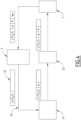
- the data bus 18 allows different equipment such as the central unit 5, the auxiliary unit 7, the data acquisition interface 14, or even the multi-axis force sensor 20, to communicate by circulating frames of data sent synchronously or cyclically.
- communication is carried out unidirectionally but allowing cross-communication in English.
- the central processing unit acts as “master” on the data bus and other connected equipment acts as “slaves”.
- These “slave” devices can read the data contained in each data frame, and add data to the data frame as it passes, the data frame being sent back to the central unit at the end of each processing cycle. communication.
- the central unit 5 transmits a data frame 30 which first arrives at the data acquisition interface 14.
- the data acquisition interface 14 completes the data frame 30 with data such as for example the positions joints q r of actuators M1 to M6.
- the data frame then reaches the multi-axis force sensor 20.
- the multi-axis force sensor 20 completes the data frame with the measured multidimensional external forces F s .
- the data frame 30 then reaches the auxiliary unit 7 which can read the joint positions q r of the electrical actuators M1 to M6 and the measured multidimensional external forces F s which have just been written in the data frame 30.
- the frame data 30 then reaches the central unit 5 which can read the joint positions q r of the electrical actuators M1 to M6 and the multidimensional external forces F s measured.
- the central unit 5 can implement cyclic communications at different frequencies. Certain data frames 30 transmitted at high frequency can be dedicated to the communication of the joint positions q r of the electrical actuators M1 to M6 while certain data frames 30 transmitted at a lower frequency can be dedicated to the communication of the multidimensional external forces F s measured. Thus, a communication loop having as starting and ending point the “master” node, which here is the central unit 5, is formed.
- the EtherCAT protocol (EtherCAT Automation Protocol) makes it possible to implement unidirectional communication in which data frames circulate following a communication loop successively connecting the central unit 5, the data acquisition interface 14, the multi-axis efforts 20 and the auxiliary unit 7.
- the EtherCAT protocol allows cross communication, that is to say the possibility for a slave to send data which will be read in the same communication cycle by another slave placed after it in the communication loop.
- the central unit 5, the auxiliary unit 7, the data acquisition interface 14 and the multi-axis force sensor 20 can communicate in pairs via different data buses.
- the multi-axis force sensor 20 can communicate directly with the axis regulation module 12, described in more detail below.
- the communication link connecting the central unit 5, the auxiliary unit 7 and the data acquisition interface 14 may include several data buses of different nature.
- the control system 8 implements an application program execution module (module 42), a trajectory generator (module 44) and an impedance manager (module 46).
- the application program execution module 42 addresses instructions to the trajectory generator 44, for example in the form of asynchronous commands.
- the application program execution module 42 also makes it possible to select the appropriate operating mode for the impedance manager 46. For example, one can choose a position control operating mode, or an effort control operating mode. , or in a hybrid operating mode mixing effort control and position control, or an impedance control mode.
- the application program execution module 42 can also return status information to a user.
- the trajectory generator 44 receives high-level instructions (for example, an instruction to move in a straight line to a given destination in space) and transforms these instructions into a succession of joint positions or Cartesian positions, for example in applying a kinematic model associated with the robot arm 4 and, where appropriate, taking into account mechanical constraints such as reductions and possible mechanical couplings.
- high-level instructions for example, an instruction to move in a straight line to a given destination in space
- transforms these instructions into a succession of joint positions or Cartesian positions for example in applying a kinematic model associated with the robot arm 4 and, where appropriate, taking into account mechanical constraints such as reductions and possible mechanical couplings.
- the trajectory generator 44 can also, in a similar manner, generate force trajectories (such as an effort in a given direction gradually passing from one value to another). Preferably, the position and effort trajectories are synchronized.
- the impedance manager 46 generates the joint commands so as to give the robot a defined behavior, for example to follow a trajectory in Cartesian space.
- commands are preferably generated using operating mode information provided by the application program execution module 42, but also and above all based on movement instructions (such as positions and speeds) and/or instructions synchronous efforts, and as a function of a quantity, denoted q mv , which will be described in more detail in the following.
- the joint commands generated by the impedance manager 46 include a composite effort and/or speed instruction, denoted "u", and a behavior matrix, denoted Y.
- Y is a square matrix of dimension n
- u is a vector of dimension n, n being the number of motors of the robot.
- the behavior matrix Y describes a desired behavior of the robot arm, by defining directions in which the composite instruction u must apply.
- the coefficients of the behavior matrix can be time-dependent functions.
- the composite instructions u can depend on time.
- the composite instructions u could be separated into two distinct variables: a speed instruction on the one hand and an effort instruction on the other hand. However, grouping them into a single variable makes it possible to limit data exchanges between components in the physical implementation.
- the term “impedance” is used to designate the mechanical impedance of the robot arm 4.
- one of the goals of the control method is to control the behavior and response of the robot arm 4 when it is subjected to external forces, for example when it encounters an obstacle or when a user exerts manual effort on the robot arm (for example to manually guide the robot).
- the mechanical impedance of the robot characterizes the response of the robot arm 4 to an external mechanical force.
- Zero (or almost zero) impedance means that the robot moves freely as soon as we try to apply force to it.
- An infinite (or very large) impedance means that the robot arm remains stationary regardless of the external force applied.
- the robot impedance can be chosen differently for different directions of space, for example by selecting very large impedance in some directions and low in other directions.
- control system 8 of the robot is configured to calculate the composite instructions u depending on time and defining joint forces and speeds, as a function of a target trajectory and a chosen operating mode, and to calculate the behavior matrix Y which describes a desired behavior of the arm robot, by defining directions in which the calculated composite instruction u must apply. This calculation can be repeated cyclically.
- the control system also includes a joint impedance regulator (module 48) which receives the composite setpoint u and the behavior matrix Y generated by the impedance manager 46, as well as the joint position and speed of the robot (respectively denoted q r and q ⁇ r ) obtained from sensors C1 to C6.
- a joint impedance regulator module 48 which receives the composite setpoint u and the behavior matrix Y generated by the impedance manager 46, as well as the joint position and speed of the robot (respectively denoted q r and q ⁇ r ) obtained from sensors C1 to C6.
- the joint impedance regulator 48 is configured to generate the joint force instructions (denoted “ ⁇ ”) so that the robot follows the behavior defined by the composite instruction u and the behavior matrix Y generated by the impedance manager 46.
- the joint impedance regulator 48 generates and/or updates the quantity q mv , which corresponds to an internal state comparable to an internal and virtual joint position setpoint, which will be used to for calculation purposes.
- the control system 8 finally includes an axis regulation module 12.
- This axis regulation module 12 implements one or more regulation loops which control the actuators so that the applied forces follow the joint force instruction ⁇ received from the joint impedance regulator 48.
- the axis regulation module axis 12 includes effort and speed loops 61 which ensure the regulation of effort and speed and generate the control instructions for the current loops ⁇ cmd which can take into account gravity compensations of the robot 4 and the effector 6.
- the joint speed q ⁇ r is for example obtained by numerical derivation of the position q r of the robot. In practice, the position and joint speed of the robot ( q r and q ⁇ r ) as well as all the joint forces can be presented in the form of vectors whose coefficients correspond to the different joints or actuators.
- the robot control system is thus configured to calculate a joint force setpoint ⁇ for controlling the axis regulation modules and the time derivative q ⁇ mv of an internal state q mv homogeneous at a joint position, this calculation being carried out as a function of said composite setpoint u previously calculated, of said behavior matrix Y, of the measured joint positions q r , of the joint velocities q ⁇ r derived from the measured joint positions q r , and of the internal state q mv .
- the robot 2 advantageously comprises a human machine interface 52 (HMI) which makes it possible to acquire commands and instructions coming from a user and to display or send information to the user, such as information on the internal state of robot 2 and/or on operating parameters.
- HMI human machine interface 52
- the control system 8 of the robot implements a calculation module 10 which incorporates the functions of the modules 42, 44, 46 and 48.
- the calculation module 10 is capable of generate the joint force instructions ⁇ for controlling an axis regulation module 12.
- This axis regulation module 12 is capable of generating the instructions for controlling the power units 15 delivering an appropriate electric current to the motors M1 at M6.
- the central unit 5 and the auxiliary unit 7 each comprise at least one processor, such as a programmable microcontroller or a microprocessor, which is coupled to a computer memory which includes executable instructions and/or software code intended to implement implements a method of controlling the robot when these instructions are executed by the processor.
- processor such as a programmable microcontroller or a microprocessor
- the central unit 5 is able to operate the functions of the modules 42, 44 and 46.
- the central unit 5 communicates to the auxiliary unit 7 the composite setpoint u and the behavior matrix Y via the data bus 18.
- the auxiliary unit 7 is able to operate the functions of the module 48, that is to say the joint impedance regulator which calculates the joint force instructions ⁇ and transmits them to the axis regulation module 12 which implements force and speed regulation loops 61 and current regulation loops 62.
- the auxiliary unit 7 is also capable of operating the functions of the axis regulation module 12, in other words the auxiliary unit 7 implements the axis regulation module 12, and therefore implements the effort and speed regulation loops 61 and the current regulation loops 62.
- the auxiliary unit 7 is connected to the 6 power units 15 and thus transmits to them power unit control instructions. For the clarity of the figure 2 , only two of the six power units are shown.
- the joint force control can be implemented by the axis regulation module 12 following well-known current regulation strategies, which are not described in more detail, the essential being that the forces exerted on each of the joints of the robot respect the calculated joint force instruction ⁇ .
- the effort control produced by the effort and speed loop 61 can also include a correction aimed at compensating the gravity of the robot arm and the friction, the friction correction being calculated for each joint from of the rotation speed determined for this joint, gravity being calculated for each joint from the angular position and the dynamic model of the robot arm 4.
- a correction can be made to the control strategy as a function of the forces and/or torques measured by the multi-axis force sensor 20.
- Different correction strategies can be implemented depending on whether a multi-axis force sensor is mounted at the end of the robot arm, or depending on whether several force sensors are associated with the respective joints of the robot arm 4.
- the calculation module 10 When a multi-axis force sensor 20 is placed between the end of the robot arm and the effector 6, the calculation module 10 then includes a gravity compensator 43 which calculates the weight of the effector F g .
- the weight of the effector F g is a vector representing the force torque of the weight of the effector 6, expressed in the reference of the multi-axis force sensor 20. It is calculated from the parameters of the tool carried by the robot (mass, position of the center of gravity), the geometric model of the robot arm and the measured joint positions q r .
- the weight of the effector F g is subtracted from the measurement of the multi-axis force sensor 20 at the level of the force and speed loops 61 so as not to take into account the weight of the effector in the control, but only the forces exerted on the effector 6.
- the calculation module 10 also includes a joint Cartesian converter 47 which calculates the conversion matrix T f .
- the joint conversion matrix T f is the matrix which makes it possible to convert the multidimensional external forces F s which are expressed in the Cartesian space into data expressed in the joint space.
- T f J f T T vs , where J f is the Jacobian matrix of the robot connecting the Cartesian speed of the center of the multi-axis force sensor 20 to the joint speeds of the robot 2 and T c is a matrix which makes it possible to transform the measurements of the multi-axis force sensor 20, initially expressed in the coordinates of the force sensor, to express them in the coordinate system of the robot base. J f and T c are calculated from the joint positions q r .
- the joint conversion matrix T f and the weight of the effector F g are transmitted to the effort and speed loops 61.
- the joint conversion matrix T f and the weight of the effector F g are transmitted to the effort and speed loops 61 via a data frame 30 which comes from the central unit 5 which implements the gravity compensator 43 and the joint Cartesian converter 47.
- the force and speed loops 61 are implemented by the auxiliary unit 7.
- the effort and speed loops 61 can first apply the joint conversion matrix T f to the weight of the effector F g and to the multidimensional external forces F s then perform the subtraction.
- the correction of the joint force instructions ⁇ in the presence of a force sensor 20, can be carried out by associating gravity compensation with two force and speed correctors, respectively denoted G f and G v which correct the joint force instructions supplied to the robot arm 4.
- the force corrector G f is an integral type regulator
- the speed corrector G v is of the proportional type.
- the gravity compensator 43 and the joint Cartesian converter 47 are implemented in the central unit 5.
- the joint conversion matrix T f and the weight of the effector F g are transmitted by the connection bus 18 to the effort and speed loops 61 which are implemented in the auxiliary unit 7.
- This implementation is advantageous because it allows all the calculations implemented in the auxiliary unit 7 to be carried out in joint coordinates. These calculations are relatively simple (unlike the calculations made in modules 43, 47, and 46). This allows the impedance regulator 48 and the effort and speed loops 61 to be calculated at a higher frequency. Furthermore, many known solutions require the effort measured by the force sensor 20 to be transmitted to the central unit so that the latter calculates position, speed or effort instructions, which are intended for controlling the actuators, thus causing more delay in the force regulation loop, which results in lower precision and lower performance when the robot must be guided manually at least in part.
- the joint impedance regulator 48 comprises a resolution module 70 and an integration module 64.
- the resolution module 70 is configured to calculate the joint force setpoints ⁇ and to transmit the joint force setpoints ⁇ calculated to the axis regulation module 12. This calculation is carried out as a function of the composite setpoint u previously calculated, of the behavior matrix Y previously calculated , measured joint positions q r , joint velocities q ⁇ r derived from the measured joint positions q r and the previously calculated internal state q mv .
- the joint force setpoint ⁇ used to control the axis regulation module 12 is calculated from a regulation function which regulates the difference between the joint position q r and the internal state q mv ( previously defined with reference to the joint impedance regulator 48).
- the resolution module 70 calculates the derivative q ⁇ mv of the internal state as a function of the composite setpoint u previously calculated, of the behavior matrix Y previously calculated, of the joint position q r , of the joint speed q ⁇ r and of the internal state q mv previously calculated.
- the integration module 64 determines the internal state q mv by integration of the time derivative q ⁇ mv of the internal state.
- the resolution module 70 uses the value of the time derivative q ⁇ mv already known from a previous calculation cycle, and stored in memory.
- the regulation function is a proportional, derivative and integral regulator (PID regulator).
- PID regulator proportional, derivative and integral regulator
- q mv is the function corresponding to said internal state
- q ⁇ mv is the time derivative of the internal state q mv
- ⁇ is the joint force set point, here presented in vector form
- Y is the behavior matrix
- u is said effort or position instruction.
- Kp, Ki, and Kd are payoff matrices.
- the gains Kp, Ki, and Kd are the gains used to configure the PID regulator.
- Kp, Ki, and Kd correspond to proportional, integral, and derivative gains, respectively.
- Kp and Ki can possibly be zero matrices.
- the second equation carries out a proportional integral derivative (PID) type control of the joint position of the robot q r on the position qmv .
- PID proportional integral derivative
- the first equation defines the evolution of the virtual position represented by the internal state q mv .
- the first implementation of the impedance regulator is particularly advantageous because the behavior matrix Y is symmetrical, so that only part of the coefficients need to be transmitted on the data bus 18, which further reduces the communication time .
- ⁇ is the intermediate variable previously described
- the robot 2 In a first operating mode, the robot 2 operates in position control.
- the robot arm 4 is controlled in position and must follow the joint trajectory generated (for example generated by the module 44) independently of the external forces exerted on the robot arm 4.
- the trajectory is defined by a joint position q d dependent on time and its derivative q ⁇ d .
- the impedance manager 48 defines a zero behavior matrix Y, that is to say that the coefficients of the behavior matrix Y are all harmed. Alternatively, this corresponds to setting P equal to the identity matrix in the second implementation of the impedance regulator described above.
- the angular position q r is controlled by the virtual position q mv and will follow the trajectory defined by the joint position q d after a transient regime whose duration is determined by the time constant T, and with a precision which will depend on the values chosen for the gains K p , K i and K d .
- the internal state q mv follows the speed instructions defined in the composite instruction u in all joint directions.
- Such an operating mode is for example useful when one wishes to leave the robot arm free to allow a user to control the robot arm entirely by a simple manual movement.
- the first equation implies that the difference between the virtual angular position q mv and the angular position q r converges to zero when the predetermined joint setpoint ⁇ d is constant.
- the gains of the PID regulator have sufficiently high values to allow us to approximate that the internal state q mv is equal to the real angular position q r even when the predetermined joint setpoint ⁇ d is not constant.
- the internal state q mv follows the measured joint positions q r of the robot arm 4 in all joint directions.
- the second equation shows that the joint force setpoint transmitted to the robot arm 4 corresponds to the predetermined joint setpoint ⁇ d , independently of the position of the robot arm 4.
- the robot 2 operates in a hybrid mode combining both effort control and position control.
- the robot arm 4 must follow a predefined trajectory, while applying controlled forces in certain directions.
- all or part of the actuators M1 to M6 exert a force which opposes the manual force exerted by the user.
- Such an operating mode can also be useful when the robot is used in an industrial process for shaping a mechanical part using an effector 6 carried by the robot arm 4, during which the effector 6 enters in direct contact with the mechanical part, for example during sanding operations, or deburring, or assembly, or following the contour of the part, and many other examples.
- Such an operating mode can finally be useful when controlling the robot arm remotely with force feedback, or when several industrial robots must collaborate to manipulate the same object, for example during a manufacturing process. of a mechanical part.
- a first example of the hybrid operating mode may concern operation with a “ball joint” type constraint, in which it is desired that the end of the robot remains at a given point ( x d , y d , z d ), the orientation being free. Furthermore, we want to be able to freely move the orientation of the end of the robot, and therefore the moments ( m x , m y , m z ) around the point of rotation must remain zero.
- J mv designates the Jacobian matrix
- the internal state q mv follows the joint positions q r measured in all force-controlled directions defined by the behavior matrix Y, that is to say in the directions corresponding to the change in orientation of the end of the robot .
- the internal state q mv follows the speed instructions defined in the composite reference u in the speed-controlled directions defined by the behavior matrix Y, that is to say in the directions corresponding to the translation from the end of the robot.
- the robot follows a trajectory in an (x,y) plane, with a fixed orientation. In the z direction orthogonal to the (x,y) plane, the robot applies a variable effort as a function of time.
- This hybrid operating mode can be useful, for example, for sanding a surface, for example in fully automatic operation.
- the trajectory generator 44 In this second hybrid operating mode, the trajectory generator 44 generates the instructions x d ( t ) and y d ( t ), which define the desired trajectory in the plane (x,y), as well as the value f z,d ( t ) of the desired effort in the z direction, and transmits them to the impedance manager 46.
- the internal state q mv follows the joint positions q r measured in all the force-controlled directions defined by the behavior matrix Y, that is to say in the joint direction corresponding to the z direction.
- the internal state q mv follows the speed instructions defined in the composite instruction u in the speed-controlled directions defined by the behavior matrix Y, that is to say in all the other joint directions.
- the internal state q mv follows the joint positions q r measured in the force-controlled directions defined by the behavior matrix Y and follows the speed instructions defined in the composite instruction u in the controlled directions in speed defined by the behavior matrix Y.
- the robot In a fourth operating mode of the "impedance control" type, the robot must behave as if it were connected to a point following a trajectory p d by means of a spring K cart and damping B cart .
- the vector p d contains the Cartesian coordinates (position and orientation) of the trajectory.
- the associated speed is noted v d .
- p mv is a vector of Cartesian coordinates (position and orientation) calculated from the internal state q mv and the geometric model of the robot.
- the characteristics of the spring K cart and the damping B cart are given here in the form of matrices.
- the impedance manager 46 For all the operating modes described, the impedance manager 46 generates the behavior matrix Y and the composite setpoint u following the commands received from the application program execution module 42 and the trajectory generator 44.
- the application program execution module 42, the trajectory generator 44 and the impedance manager 46 are advantageously implemented by the central unit 5.
- the joint impedance regulator 48 and the axis regulation module 12 are implemented by the auxiliary unit 7.
- the central unit 5 is configured to periodically recalculate the composite setpoint u and the behavior matrix Y with a first calculation frequency, denoted F1.
- the joint force instructions ⁇ are recalculated periodically in the auxiliary unit with a second calculation frequency, denoted F2, which is greater than the first frequency F1.
- the second frequency F2 is between two and twenty times higher than the first frequency F1.
- the second frequency F2 is between five and ten times higher than the first frequency F1.
- the second frequency F2 is eight times higher than the first frequency F1.
- the joint impedance regulator only needs to implement a relatively limited number of simple arithmetic operations. It can therefore operate at high frequency. This makes it possible to have high Kp, Ki and Kd gains, which makes it possible to obtain good stiffness and good precision in the position-controlled directions. More complex geometric calculations are implemented in central unit 5.
- implementing impedance regulation in the auxiliary unit 7 separately from the central unit 5 provides a performance gain because a single processor then controls the different actuators M1 to M6. By being as close as possible to the sensors and actuators, this makes it possible to have reduced delays in the controls, and therefore to ultimately obtain superior performance.
- Implementing impedance regulation and axis regulation module 12 in a single processor of auxiliary unit 7 increases performance because there is no communication delay.
- the composite instructions u and the behavior matrices Y are calculated by the central unit 5 and transferred to the auxiliary unit 7 every 1 millisecond, i.e. with a frequency of 1000 Hz.
- Each of the components of these commands are then linearly interpolated to obtain values for each of the calculation cycles carried out with the second frequency F2, for example with a frequency of 8kHz.
- Another advantageous aspect of the implementation of the invention lies in the fact that all the calculations carried out by the impedance regulator 48 including the integration of the internal state q mv are carried out in the joint coordinates . This avoids having to implement geometric transformations that are costly in computational resources. Reducing the time necessary to carry out the calculations linked to impedance regulation during each calculation cycle also makes it possible to have higher Kp, Ki, Kd gains, and therefore to obtain better precision, particularly in the directions controlled in position.
- the impedance regulation method makes it possible to operate efficiently regardless of the operating mode chosen, whether the robot operates in effort control mode, or in position control mode, or in hybrid mode or in control mode. impedance.
- the values of the gain coefficients Kp, Ki and Kd can be set once and for all, independently of the operating mode.
- the central unit 5 is configured to periodically recalculate the joint conversion matrix T f and the weight of the effector F g with a third calculation frequency, denoted F3 and lower than the second frequency F2.
- the second frequency F2 is between two and twenty times higher than the third frequency F3.
- the second frequency F2 is between five and ten times higher than the third frequency F3.
- the second frequency F2 is eight times higher than the third frequency F3.
- the guidance of the robot is improved when the robot must be guided manually at least partially.
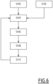
- the method begins at step S100 for example with the launch of a robot control program, in particular in a manual or hybrid guidance mode. During this step, depending on the operating mode chosen, a trajectory can be acquired or defined by the control system 8.
- a user can, during a step S102, manipulate the robot arm 4 to manually impose an effort or movement.
- control system 8 calculates in the impedance manager 46 implemented by the central unit 5 the composite setpoint u defining joint forces and speeds, depending on the target trajectory and the operating mode .
- control system 8 calculates in the impedance manager 46 implemented by the central unit 5 the behavior matrix Y as a function of the operating mode.
- the control system 8 calculates in the impedance regulator 48 implemented by the auxiliary unit 7 the joint force setpoint ⁇ and the time derivative q ⁇ mv of said internal state q mv , this calculation being carried out as a function of said composite setpoint u previously calculated, of the behavior matrix Y, of the measured joint positions q r , of joint velocities q ⁇ r derived from the measured joint positions and the internal state.
- the joint force setpoint for controlling the axis regulation modules 12 is calculated from a regulation function which regulates the difference between the joint position q r and the internal state q mv , l the internal state being determined by integration of said time derivative q ⁇ mv of the internal state q mv .
- step S110 the control system 8 calculates the control instructions for the power units 15 as a function of the joint force instruction ⁇ .
- the calculation of the control instructions for the power units 15 is also a function of the measurements of the phase currents of the actuators and the joint positions q r measured because it includes a current regulation loop, that is to say that it takes into account the difference between current measurements and current instructions.
- account is taken of an external force applied to the robot, for example by a user manually exerting a force on the robot arm 4.
- the invention has been described with a robot arm articulated following rotations. It is applicable to a robot comprising members in translation relative to each other.
Landscapes
- Engineering & Computer Science (AREA)
- Robotics (AREA)
- Mechanical Engineering (AREA)
- Human Computer Interaction (AREA)
- Automation & Control Theory (AREA)
- Artificial Intelligence (AREA)
- Physics & Mathematics (AREA)
- Evolutionary Computation (AREA)
- Fuzzy Systems (AREA)
- Mathematical Physics (AREA)
- Software Systems (AREA)
- Computer Networks & Wireless Communication (AREA)
- Manipulator (AREA)
Abstract
Ce procédé de commande d'un robot industriel comporte des étapes consistant à :▪ calculer (S104) dans des modules implémentés par l'unité centrale une consigne composite dépendant du temps et définissant des efforts et des vitesses articulaires, en fonction d'une trajectoire cible et d'un mode de fonctionnement,▪ calculer (S106) dans des modules implémentés par l'unité centrale une matrice de comportement qui décrit un comportement désiré du bras de robot, en définissant des directions dans lesquelles la consigne composite calculée doit s'appliquer,▪ calculer (S108) dans un module implémenté par l'unité auxiliaire une consigne d'effort articulaire de pilotage du module de régulation d'axe,▪ calculer (S110) dans un module de régulation d'axe implémenté par l'unité auxiliaire les consignes de pilotage des unités de puissance en fonction de la consigne d'effort articulaire.This method of controlling an industrial robot comprises steps consisting of: ▪ calculating (S104) in modules implemented by the central unit a composite setpoint depending on time and defining joint forces and speeds, as a function of a trajectory target and an operating mode, ▪ calculate (S106) in modules implemented by the central unit a behavior matrix which describes a desired behavior of the robot arm, by defining directions in which the calculated composite setpoint must be apply,▪ calculate (S108) in a module implemented by the auxiliary unit an articular force setpoint for controlling the axis regulation module,▪ calculate (S110) in an axis regulation module implemented by the unit auxiliary the control instructions of the power units according to the joint effort instruction.
Description
La présente invention concerne les robots industriels, et porte plus particulièrement sur des systèmes et des procédés de commande d'un robot industriel manuellement guidable.The present invention relates to industrial robots, and more particularly relates to systems and methods for controlling a manually steerable industrial robot.
Les robots industriels, tels que les bras de robot, sont de plus en plus utilisés dans des applications de collaboration directe avec des opérateurs, dans lesquels les opérateurs peuvent agir directement sur le robot. C'est par exemple le cas d'applications chirurgicales, ou de certains procédés de fabrication industrielle, entre autres.Industrial robots, such as robot arms, are increasingly used in direct operator collaboration applications, in which operators can act directly on the robot. This is for example the case for surgical applications, or certain industrial manufacturing processes, among others.
Par exemple, l'opérateur peut agir directement sur le robot en manipulant et en déplaçant une partie du bras de robot. Ce déplacement est détecté par des capteurs du robot. En fonction de ce retour, le système de commande du robot modifie en conséquence des consignes envoyées aux moteurs du robot, par exemple pour amener ou maintenir le bras de robot à la position choisie par l'opérateur, ou pour accompagner un déplacement manuel du robot par l'opérateur.For example, the operator can act directly on the robot by manipulating and moving part of the robot arm. This movement is detected by the robot's sensors. Depending on this feedback, the robot control system accordingly modifies the instructions sent to the robot motors, for example to bring or maintain the robot arm in the position chosen by the operator, or to accompany a manual movement of the robot. by the operator.
Généralement, la performance du guidage « manuel » d'un robot peut être mesurée par différents critères, tels que la facilité avec laquelle le robot peut être déplacé (la transparence), l'absence d'élasticité sous l'action de l'opérateur (la rigidité) et la stabilité, qui s'évalue lorsque que le robot atteint une position limite imposée par programmation ou par l'utilisateur.Generally, the performance of "manual" guidance of a robot can be measured by different criteria, such as the ease with which the robot can be moved (transparency), the absence of elasticity under the action of the operator (rigidity) and stability, which is evaluated when the robot reaches a limit position imposed by programming or by the user.
Aucune des solutions de contrôle de robot disponibles et connues à l'heure actuelle ne permet d'obtenir des résultats qui satisfassent ces trois critères, qui sont souvent difficiles à concilier.None of the robot control solutions currently available and known can achieve results that satisfy these three criteria, which are often difficult to reconcile.
En effet, en pratique, un robot présentant une rigidité et une transparence satisfaisantes présentera une stabilité insuffisante, car il sera sujet à des rebonds lorsqu'il rentrera en contact avec un élément rigide de son environnement sous l'action d'un opérateur, par exemple.Indeed, in practice, a robot presenting satisfactory rigidity and transparency will present insufficient stability, because it will be subject to rebounds when it comes into contact with a rigid element of its environment under the action of an operator, for example example.
Il existe donc un besoin pour des systèmes et des procédés de commande de robots industriels permettant un guidage qui présente des performances améliorées lorsque le robot doit être guidé manuellement au moins partiellement.There is therefore a need for systems and methods for controlling industrial robots allowing guidance which has improved performance when the robot must be guided manually at least partially.
A cet effet, l'invention concerne un procédé de commande d'un robot industriel, le robot comportant :
- un bras de robot multiaxes comprenant au moins deux actionneurs électriques chacun capable de déplacer une partie du bras de robot par rapport à une autre partie du bras de robot autour ou le long d'un axe de mouvement, chaque actionneur électrique étant associé à un capteur configuré pour mesurer une position articulaire de l'actionneur correspondant,
- un effecteur placé à l'extrémité du bras de robot,
- un système de commande de robot comportant
- une unité centrale,
- une unité auxiliaire configurée pour piloter des unités de puissance, implémentant un module de régulation d'axe comprenant des boucles de régulation de courant aptes à générer des consignes de pilotage des unités de puissance,
- des unités de puissance aptes à délivrer un courant électrique approprié aux actionneurs électriques,
- une interface d'acquisition de données configurée pour recevoir et transmettre les mesures des capteurs associés aux actionneurs électriques,
- une liaison de communication connectant l'unité centrale, l'unité auxiliaire et l'interface d'acquisition de données, la liaison de communication comportant un bus de données,
- calculer dans des modules implémentés par l'unité centrale une consigne composite dépendant du temps et définissant des efforts et des vitesses articulaires, en fonction d'une trajectoire cible et d'un mode de fonctionnement,
- calculer dans des modules implémentés par l'unité centrale une matrice de comportement qui décrit un comportement désiré du bras de robot, en définissant des directions dans lesquelles la consigne composite calculée doit s'appliquer,
- calculer dans un module de régulation d'impédance articulaire implémenté par l'unité auxiliaire une consigne d'effort articulaire de pilotage du module de régulation d'axe en fonction de ladite consigne composite précédemment calculée, et de ladite matrice de comportement,
- calculer dans le module de régulation d'axe implémenté par l'unité auxiliaire les consignes de pilotage des unités de puissance en fonction de la consigne d'effort articulaire.
- a multi-axis robot arm comprising at least two electric actuators each capable of moving a part of the robot arm relative to another part of the robot arm around or along an axis of movement, each electric actuator being associated with a sensor configured to measure a joint position of the corresponding actuator,
- an effector placed at the end of the robot arm,
- a robot control system comprising
- a central unit,
- an auxiliary unit configured to control power units, implementing an axis regulation module comprising current regulation loops capable of generating control instructions for the power units,
- power units capable of delivering an appropriate electric current to the electric actuators,
- a data acquisition interface configured to receive and transmit measurements from the sensors associated with the electric actuators,
- a communication link connecting the central unit, the auxiliary unit and the data acquisition interface, the communication link comprising a data bus,
- calculate in modules implemented by the central unit a composite setpoint depending on time and defining joint forces and speeds, according to a target trajectory and an operating mode,
- calculate in modules implemented by the central unit a behavior matrix which describes a desired behavior of the robot arm, by defining directions in which the calculated composite instruction must apply,
- calculate in a joint impedance regulation module implemented by the auxiliary unit a joint force setpoint for controlling the axis regulation module as a function of said previously calculated composite setpoint, and of said behavior matrix,
- calculate in the axis regulation module implemented by the auxiliary unit the control instructions for the power units as a function of the joint force instruction.
Dans certains modes de réalisation, les unités de puissance comprennent des capteurs de mesure de courants de phases desdits actionneurs électriques, et dans lequel le calcul des consignes de pilotage est mis en oeuvre par les boucles de régulation de courant, et est fonction en outre des mesures des courants de phases desdits actionneurs électriques.In certain embodiments, the power units comprise phase current measurement sensors of said electrical actuators, and in which the calculation of the control instructions is implemented by the current regulation loops, and is also a function of the measurements of the phase currents of said electrical actuators.
Dans certains modes de réalisation, le calcul de la consigne d'effort articulaire comporte le calcul de la dérivée temporelle d'un état interne homogène à une position articulaire, ce calcul étant réalisé en fonction de ladite consigne composite précédemment calculée, de ladite matrice de comportement, des positions articulaires mesurées, de vitesses articulaires dérivées à partir des positions articulaires mesurées, et de l'état interne.In certain embodiments, the calculation of the joint force setpoint comprises the calculation of the time derivative of a homogeneous internal state at a joint position, this calculation being carried out as a function of said previously calculated composite setpoint, of said matrix of behavior, measured joint positions, joint velocities derived from measured joint positions, and internal state.
Dans certains modes de réalisation, la consigne d'effort articulaire de pilotage du module de régulation d'axe est calculée à partir d'une fonction de régulation qui régule l'écart entre la position articulaire et l'état interne, l'état interne étant déterminé par intégration de ladite dérivée temporelle de l'état interne.In certain embodiments, the joint force setpoint for controlling the axis regulation module is calculated from a regulation function which regulates the difference between the joint position and the internal state, the internal state being determined by integration of said time derivative of the internal state.
Dans certains modes de réalisation, l'unité centrale recalcule la consigne composite et la matrice de comportement avec une première fréquence et l'unité auxiliaire recalcule les consignes d'effort articulaire de pilotage du module de régulation d'axe avec une deuxième fréquence supérieure à la première fréquence.In certain embodiments, the central unit recalculates the composite setpoint and the behavior matrix with a first frequency and the auxiliary unit recalculates the joint force setpoints for controlling the axis regulation module with a second frequency greater than the first frequency.
Dans certains modes de réalisation, la deuxième fréquence est entre deux et vingt fois plus élevée que la première fréquence, de préférence entre cinq et dix fois plus élevée que la première fréquence, de préférence encore huit fois plus élevée que la première fréquence.In some embodiments, the second frequency is between two and twenty times higher than the first frequency, preferably between five and ten times higher than the first frequency, more preferably eight times higher than the first frequency.
Dans certains modes de réalisation, l'unité auxiliaire calcule les consignes d'effort articulaire de pilotage du module de régulation d'axe avec une fréquence est choisie entre 500Hz et 20kHz, de préférence entre 5KHz et 12KHz, de préférence égale à 8KHz.In certain embodiments, the auxiliary unit calculates the joint force instructions for controlling the axis regulation module with a frequency chosen between 500Hz and 20kHz, preferably between 5KHz and 12KHz, preferably equal to 8KHz.
Dans certains modes de réalisation, le module de régulation d'axe prend en compte des efforts mesurés par un capteur d'effort lors du calcul des consignes de pilotage des unités de puissance en fonction de la consigne d'effort articulaire.In certain embodiments, the axis regulation module takes into account forces measured by a force sensor when calculating the control instructions for the power units as a function of the joint force instruction.
Dans certains modes de réalisation, l'unité centrale implémente un compensateur de gravité qui calcule le poids de l'effecteur et un convertisseur cartésien articulaire qui calcule la matrice de conversion à partir des positions articulaires et transmet le poids de l'effecteur et la matrice de conversion au module de régulation d'axe pour la prise en compte des efforts mesurés par un capteur d'effort monté en extrémité du bras de robot.In some embodiments, the CPU implements a gravity compensator that calculates the weight of the effector and a joint Cartesian converter that calculates the conversion matrix from the joint positions and transmits the weight of the effector and the matrix conversion to the axis regulation module to take into account the forces measured by a force sensor mounted at the end of the robot arm.
Dans certains modes de réalisation, l'unité centrale implémente un compensateur de gravité qui calcule le poids de l'effecteur et un convertisseur cartésien articulaire qui calcule la matrice de conversion à partir des positions articulaires et transmet à la première fréquence le poids de l'effecteur et la matrice de conversion au module de régulation d'axe pour la prise en compte des efforts mesurés par un capteur d'effort monté en extrémité du bras de robot.In some embodiments, the CPU implements a gravity compensator that calculates the weight of the effector and a joint Cartesian converter that calculates the conversion matrix from the joint positions and transmits at the first frequency the weight of the effector and the conversion matrix to the axis regulation module for taking into account the forces measured by a force sensor mounted in end of the robot arm.
Dans certains modes de réalisation, la liaison de communication est configurée de sorte à ce que l'unité centrale envoie de façon cyclique des trames de communication sur le bus de données, les modules de régulation d'axe et le capteur d'effort étant configurés pour lire ou ajouter des données dans la trame de données lors du passage de celle-ci, la trame de données étant remontée à l'unité centrale en fin de chaque cycle de communicationIn some embodiments, the communication link is configured so that the central processing unit cyclically sends communication frames on the data bus, the axis regulation modules and the force sensor being configured to read or add data in the data frame as it passes, the data frame being sent back to the central unit at the end of each communication cycle
Selon un autre aspect, l'invention concerne un système de commande d'un robot industriel, le robot comportant :
- un bras de robot multiaxes comprenant au moins deux actionneurs électriques chacun capable de déplacer une partie du bras de robot par rapport à une autre partie du bras de robot autour ou le long d'un axe de mouvement, chaque actionneur électrique étant associé à un capteur configuré pour mesurer une position articulaire de l'actionneur correspondant,
- un effecteur placé à l'extrémité du bras de robot,
- le système de commande de robot comportant
- une unité centrale,
- une unité auxiliaire configurée pour piloter des unités de puissance, implémentant un module de régulation d'axe comprenant des boucles de régulation de courant aptes à générer des consignes de pilotage des unités de puissance,
- des unités de puissance aptes à délivrer un courant électrique approprié aux actionneurs électriques,
- une interface d'acquisition de données configurée pour recevoir et transmettre les mesures des capteurs associés aux actionneurs électriques
- une liaison de communication connectant l'unité centrale, l'unité auxiliaire et l'interface d'acquisition de données, la liaison de communication comportant un bus de données,
- l'unité centrale implémente des modules configurés pour calculer une consigne composite dépendant du temps et définissant des efforts et des vitesses articulaires, en fonction d'une trajectoire cible et d'un mode de fonctionnement, et calculer une matrice de comportement qui décrit un comportement désiré du bras de robot, en définissant des directions dans lesquelles la consigne composite calculée doit s'appliquer,
- l'unité auxiliaire implémente un module de régulation d'impédance articulaire, configuré pour calculer une consigne d'effort articulaire de pilotage du module de régulation d'axe en fonction de ladite consigne composite précédemment calculée, et de ladite matrice de comportement, et le module de régulation d'axe configuré pour calculer les consignes de pilotage des unités de puissance en fonction de la consigne d'effort articulaire.
- a multi-axis robot arm comprising at least two electric actuators each capable of moving a part of the robot arm relative to another part of the robot arm around or along an axis of movement, each electric actuator being associated with a sensor configured to measure a joint position of the corresponding actuator,
- an effector placed at the end of the robot arm,
- the robot control system comprising
- a central unit,
- an auxiliary unit configured to control power units, implementing an axis regulation module comprising current regulation loops capable of generating control instructions for the power units,
- power units capable of delivering an appropriate electric current to the electric actuators,
- a data acquisition interface configured to receive and transmit measurements from sensors associated with the electrical actuators
- a communication link connecting the central unit, the auxiliary unit and the data acquisition interface, the communication link comprising a data bus,
- the central unit implements modules configured to calculate a composite setpoint depending on time and defining joint forces and speeds, as a function of a target trajectory and an operating mode, and calculate a behavior matrix which describes a behavior desired of the robot arm, by defining directions in which the calculated composite setpoint must apply,
- the auxiliary unit implements a joint impedance regulation module, configured to calculate a joint force setpoint for controlling the axis regulation module as a function of said composite setpoint previously calculated, and of said behavior matrix, and the axis regulation module configured to calculate the control instructions for the power units based on the joint force instruction.
Selon un autre aspect, l'invention concerne un robot industriel comportant un tel système de commande apte à mettre en oeuvre un procédé de commande tel que décrit.According to another aspect, the invention relates to an industrial robot comprising such a control system capable of implementing a control method as described.
L'invention sera mieux comprise et d'autres avantages de celle-ci apparaîtront plus clairement à la lumière de la description qui va suivre, donnée uniquement à titre d'exemple et faite en référence aux dessins annexés, dans lesquels :
- [
Fig 1 ] lafigure 1 représente schématiquement et en blocs structurels un robot industriel selon l'invention conformément à un mode de réalisation ; - [
Fig 2 ] lafigure 2 est un schéma bloc fonctionnel du robot industriel de lafigure 1 conformément au mode de réalisation de lafigure 1 ; - [
Fig 3 ] lafigure 3 est un schéma fonctionnel synthétique illustrant le système de commande conforme à l'invention ; - [
Fig 4 ] lafigure 4 est un schéma bloc illustrant la communication de données entre unités du robot ; - [
Fig 5 ] lafigure 5 est un schéma fonctionnel détaillant les boucles d'effort et de vitesses ; - [
Fig 6 ] lafigure 6 représente schématiquement un procédé de commande d'un robot industriel conforme à l'invention.
- [
Figure 1 ] therefigure 1 represents schematically and in structural blocks an industrial robot according to the invention in accordance with one embodiment; - [
Figure 2 ] therefigure 2 is a functional block diagram of the industrial robot of thefigure 1 in accordance with the embodiment of thefigure 1 ; - [
Figure 3 ] thereFigure 3 is a synthetic functional diagram illustrating the control system according to the invention; - [
Figure 4 ] thereFigure 4 is a block diagram illustrating data communication between robot units; - [
Figure 5 ] thereFigure 5 is a functional diagram detailing the effort and speed loops; - [
Figure 6 ] thereFigure 6 schematically represents a method of controlling an industrial robot according to the invention.
La
Le robot 2 comporte un bras de robot multiaxes 4. Par exemple, le bras de robot 4 comporte plusieurs segments articulés deux à deux autour d'axes de rotation.The
Le bras de robot 4 peut comporter un effecteur 6, tel qu'un outil pilotable, qui est placé en bout du bras de robot 4.The
Le bras de robot 4 comporte une pluralité d'actionneurs électriques, notés M1, M2, M3, M4, M5 et M6 sur l'exemple de la
Chaque actionneur électrique M1 à M6 comporte un moteur électrique, tels que des moteurs électriques synchrones sans balais, ou tout autre moteur électrique adapté.Each electric actuator M1 to M6 comprises an electric motor, such as brushless synchronous electric motors, or any other suitable electric motor.
Le robot 2 comporte aussi une pluralité de capteurs, notés C1, C2, C3, C4, C5 et C6 sur l'exemple de la
Chaque actionneur électrique M1 à M6 est associé à un capteur C1 à C6. Chaque capteur C1 à C6 est configuré pour mesurer une position articulaire de cet actionneur électrique. Par exemple, les capteurs C1 à C6 sont des capteurs d'angle, tels que des codeurs rotatifs. La position articulaire correspond par exemple à une position angulaire de l'articulation.Each electric actuator M1 to M6 is associated with a sensor C1 to C6. Each sensor C1 to C6 is configured to measure a joint position of this electric actuator. For example, sensors C1 to C6 are angle sensors, such as rotary encoders. The joint position corresponds for example to an angular position of the joint.
De préférence, le robot 2 est un robot à 6 axes. Le bras de robot 4 présente donc six degrés de liberté et comporte six actionneurs électriques M1 à M6 et six capteurs C1 à C6.Preferably,
Le robot 2 comporte également un système de commande 8.The
Dans le mode de réalisation illustré sur les
- une unité centrale 5,
- une unité auxiliaire 7, et
- 6 unités de puissance 15.
- a
central unit 5, - an
auxiliary unit 7, and - 6
power units 15.
Au sens de la présente description, le qualificatif « articulaire » est utilisé pour désigner soit la position (angulaire) de chaque articulation du bras de robot 4, soit la position (angulaire) courante de chaque actionneur M1 à M6 du robot. L'expression « efforts articulaires » désigne les efforts commandés sur chaque articulation du bras de robot, ou sur chaque actionneur M1 à M6.For the purposes of this description, the term “articular” is used to designate either the (angular) position of each joint of the
De manière classique, une position spatiale est définie soit dans un espace cartésien, soit dans l'espace articulaire, dans lequel sont exprimées les positions articulaires de chaque articulation du bras de robot.Conventionally, a spatial position is defined either in a Cartesian space or in the joint space, in which the joint positions of each joint of the robot arm are expressed.
Dans cette description, on désigne par « effort » une force ou un couple mécanique.In this description, “effort” means a mechanical force or torque.
L'unité centrale 5 est en communication avec l'unité auxiliaire 7 par une liaison de données tel qu'un bus de données 18, notamment un bus de terrain.The
En pratique, l'unité auxiliaire 7 est connectée électriquement à des unités de puissance 15 qui délivrent un courant électrique approprié aux actionneurs M1 à M6 par l'intermédiaire de conducteurs électriques 16.In practice, the
L'unité de puissance 15 est un dispositif comprenant des interrupteurs commandables couplés à une alimentation et apte à générer les courants dans les phases d'un moteur en fonction de signaux de commande des interrupteurs appelés consignes de pilotage d'unité de puissance. Il comprend des capteurs de mesure des courants de phase des moteurs. Ces mesures de courants sont transmises à la boucle de régulation de courant 62 de manière à adapter le pilotage des interrupteurs commandables de l'unité de puissance par rétroaction.The
Le système de commande 8 comporte également une interface d'acquisition de données 14, telle qu'une carte électronique. L'interface d'acquisition de données 14 est connectée aux capteurs C1 à C6 et est configurée pour recevoir les données mesurées par les capteurs C1 à C6.The
Par exemple, les capteurs C1 à C6 sont connectés à l'interface d'acquisition 14 par des liaisons de communication compatibles avec un protocole de communication industriel, tel que le protocole EnDat, ou équivalent.For example, the sensors C1 to C6 are connected to the
L'interface d'acquisition de données 14 est connectée à l'unité centrale 5 et à l'unité auxiliaire 7 par une liaison de données tel qu'un bus de données 18, notamment un bus de terrain.The
De préférence, le bus de données 18 est compatible avec le protocole de communication EtherCAT (Ethernet for Control Automation Technology).Preferably, the
Les constituants du système de commande 8 peuvent avantageusement être regroupés dans une armoire de commande. En alternative, l'interface de d'acquisition de données 14 peut être placée dans le bras de robot comme les actionneurs M1 à M6 et les capteurs C1 à C6. L'unité centrale 5, l'unité auxiliaire 7 et les unités de puissance 15 peuvent être placés dans une armoire de commande 35 visible en pointillés sur la
Optionnellement, un capteur d'efforts multiaxes 20 placé sur le bras de robot 4 peut être connecté à l'unité centrale 5 et à l'unité auxiliaire 7, par exemple par l'intermédiaire du bus de données 18.Optionally, a
De préférence, le capteur d'efforts multiaxes 20 est placé entre l'extrémité du bras de robot 4 et l'effecteur 6. De préférence, le capteur d'efforts multiaxes 20 est constitué d'au moins 6 dispositifs de mesures, par exemple des jauges de contraintes piezo-résistives solidaires d'un corps d'épreuve. L'agencement géométrique des dispositifs, non nécessairement aligné sur un repère cartésien canonique, permet de reconstruire le torseur d'effort complet par combinaison linéaire des mesures qu'il produit. Le capteur d'efforts multiaxes 20 est configuré pour fournir les efforts extérieurs multidimensionnels Fs .Preferably, the
Dans certaines variantes, toutefois, les efforts extérieurs exercés sur le bras de robot pourraient être déterminés par la mesure des courants des actionneurs. La fonction du capteur d'efforts multiaxes 20 pourrait alors être remplacée par un module d'analyse implémenté de façon électronique par le système de commande 8.In certain variants, however, the external forces exerted on the robot arm could be determined by measuring the currents of the actuators. The function of the
Le bus de données 18 permet aux différents équipements tels que l'unité centrale 5, l'unité auxiliaire 7, l'interface d'acquisition de données 14, voire le capteur d'effort multiaxes 20, de communiquer en faisant circuler des trames de données envoyées de façon synchrone ou cyclique.The
De préférence, la communication est réalisée de façon unidirectionnelle mais en permettant une communication croisée (cross-communication en anglais).Preferably, communication is carried out unidirectionally but allowing cross-communication in English.
Par exemple, l'unité centrale (CPU) agit comme « maître » sur le bus de données et les autres équipements connectés agissent comme « esclaves ». Ces équipements « esclaves » peuvent lire les données contenues dans chaque trame de données, et ajouter des données dans la trame de données lors du passage de celle-ci, la trame de données étant remontée à l'unité centrale en fin de chaque cycle de communication.For example, the central processing unit (CPU) acts as “master” on the data bus and other connected equipment acts as “slaves”. These “slave” devices can read the data contained in each data frame, and add data to the data frame as it passes, the data frame being sent back to the central unit at the end of each processing cycle. communication.
Comme illustré sur la
En variante, l'unité centrale 5 peut mettre en oeuvre des communications cycliques à des fréquences différentes. Certaines trames de données 30 émises à haute fréquence peuvent être dédiées à la communication des positions articulaires qr des actionneurs électriques M1 à M6 alors que certaines trames de données 30 émises à une fréquence plus basse peuvent être dédiées à la communication des efforts extérieurs multidimensionnels Fs mesurés. Ainsi, une boucle de communication ayant comme point de départ et d'arrivée le noeud « maître », qui est ici l'unité centrale 5, est formée.Alternatively, the
Le protocole EtherCAT (EtherCAT Automation Protocol) permet d'implémenter une communication unidirectionnelle dans laquelle des trames de données circulent en suivant une boucle de communication reliant successivement l'unité centrale 5, l'interface d'acquisition de données 14, le capteur d'efforts multiaxes 20 et l'unité auxiliaire 7. De plus, le protocole EtherCAT permet la communication croisée c'est-à-dire la possibilité pour un esclave d'envoyer des données qui vont être lues dans le même cycle de communication par un autre esclave placé après lui dans la boucle de communication.The EtherCAT protocol (EtherCAT Automation Protocol) makes it possible to implement unidirectional communication in which data frames circulate following a communication loop successively connecting the
En variante, l'unité centrale 5, l'unité auxiliaire 7, l'interface d'acquisition de données 14 et le capteur d'efforts multiaxes 20 peuvent communiquer deux à deux par des bus de données différents. En particulier, le capteur d'efforts multiaxes 20 peut communiquer directement avec le module de régulation d'axe 12, décrit plus en détail ci-après. Autrement dit, la liaison de communication connectant l'unité centrale 5, l'unité auxiliaire7 et l'interface d'acquisition de données 14 peut comporter plusieurs bus de données de nature différente.Alternatively, the
La
Le système de commande 8 implémente un module d'exécution de programme applicatif (module 42), un générateur de trajectoire (module 44) et un gestionnaire d'impédance (module 46).The
Le module d'exécution de programme applicatif 42 adresse des instructions au générateur de trajectoire 44, par exemple sous la forme de commandes asynchrones.The application
Le module d'exécution de programme applicatif 42 permet également de sélectionner le mode de fonctionnement approprié pour le gestionnaire d'impédance 46. Par exemple, on peut choisir un mode de fonctionnement en pilotage en position, ou un mode de fonctionnement en pilotage en effort, ou dans un mode de fonctionnement hybride mêlant pilotage en effort et pilotage en position, ou un mode de commande en impédance.The application
Le module d'exécution de programme applicatif 42 peut aussi renvoyer des informations d'état à un utilisateur.The application
Le générateur de trajectoire 44 reçoit des instructions de haut niveau (par exemple, une instruction de se déplacer en ligne droite à une destination donnée dans l'espace) et transforme ces instructions en une succession de positions articulaires ou de positions cartésiennes, par exemple en appliquant un modèle cinématique associé au bras de robot 4 et, le cas échéant, en tenant compte de contraintes mécaniques telles que des réductions et des couplages mécaniques éventuels.The
Le générateur de trajectoire 44 peut aussi, de manière similaire, générer des trajectoires d'effort (comme un effort dans une direction donnée passant progressivement d'une valeur à une autre). De préférence, les trajectoires de position et d'effort sont synchronisées.The
Le gestionnaire d'impédance 46 génère les commandes articulaires de manière à conférer au robot un comportement défini, par exemple pour suivre une trajectoire dans l'espace cartésien.The
Ces commandes sont de préférence générées en utilisant une information de mode de fonctionnement fournie par le module d'exécution de programme applicatif 42, mais aussi et surtout en fonction de consignes de mouvement (telles que des positions et des vitesses) et/ou des consignes d'effort synchrones, et en fonction d'une quantité, notée qmv , qui sera décrite plus en détail dans ce qui suit.These commands are preferably generated using operating mode information provided by the application
Par exemple, les commandes articulaires générées par le gestionnaire d'impédance 46 comportent une consigne composite d'effort et/ou de vitesse, notée « u », et une matrice de comportement, notée Y. Par exemple, Y est une matrice carrée de dimension n, et u est un vecteur de dimension n, n étant le nombre de moteurs du robot. La matrice de comportement Y décrit un comportement désiré du bras de robot, en définissant des directions dans lesquelles la consigne composite u doit s'appliquer. Les coefficients de la matrice de comportement peuvent être des fonctions dépendant du temps. De même, les consignes composites u peuvent dépendre du temps.For example, the joint commands generated by the
En variante, les consignes composites u pourraient être séparées en deux variables distinctes : une consigne de vitesse d'une part et une consigne d'effort d'autre part. Toutefois, les regrouper en une seule variable permet de limiter les échanges de données entre composants dans l'implémentation physique.Alternatively, the composite instructions u could be separated into two distinct variables: a speed instruction on the one hand and an effort instruction on the other hand. However, grouping them into a single variable makes it possible to limit data exchanges between components in the physical implementation.
Dans cette description, le terme « impédance » est utilisé pour désigner l'impédance mécanique du bras de robot 4. En effet, un des buts du procédé de commande est de contrôler le comportement et la réponse du bras de robot 4 lorsqu'il est soumis à des efforts extérieurs, par exemple lorsqu'il rencontre un obstacle ou lorsqu'un utilisateur exerce un effort manuel sur le bras de robot (par exemple pour guider manuellement le robot).In this description, the term “impedance” is used to designate the mechanical impedance of the
L'impédance mécanique du robot caractérise la réponse du bras de robot 4 à un effort mécanique extérieur. Une impédance nulle (ou quasi-nulle) signifie que le robot se déplace librement dès qu'on tente d'appliquer un effort sur lui. Une impédance infinie (ou très grande) signifie que le bras de robot reste immobile quel que soit l'effort extérieur appliqué. L'impédance du robot peut être choisie différemment pour différentes directions de l'espace, par exemple en sélectionnant une impédance très grande dans certaines directions et faible dans d'autres directions.The mechanical impedance of the robot characterizes the response of the
De façon générale, le système de commande 8 du robot est configuré pour calculer les consignes composites u dépendant du temps et définissant des efforts et des vitesses articulaires, en fonction d'une trajectoire cible et d'un mode de fonctionnement choisi, et pour calculer la matrice de comportement Y qui décrit un comportement désiré du bras de robot, en définissant des directions dans lesquelles la consigne composite u calculée doit s'appliquer. Ce calcul peut être répété de façon cyclique.Generally, the
Le système de commande comporte également un régulateur d'impédance articulaire (module 48) qui reçoit la consigne composite u et la matrice de comportement Y générées par le gestionnaire d'impédance 46, ainsi que la position et la vitesse articulaire du robot (respectivement notées qr et q̇r ) obtenues à partir des capteurs C1 à C6.The control system also includes a joint impedance regulator (module 48) which receives the composite setpoint u and the behavior matrix Y generated by the
A partir de ces informations, le régulateur d'impédance articulaire 48 est configuré pour générer les consignes d'effort articulaire (notées « τ ») pour que le robot suive le comportement défini par la consigne composite u et la matrice de comportement Y générées par le gestionnaire d'impédance 46. En plus, le régulateur d'impédance articulaire 48 génère et/ou met à jour la quantité qmv , qui correspond à un état interne assimilable à une consigne de position articulaire interne et virtuelle, qui sera utilisée à des fins de calcul.From this information, the
Le système de commande 8 comporte enfin un module de régulation d'axe 12.The
Ce module de régulation d'axe 12 met en oeuvre une ou plusieurs boucles de régulation qui pilotent les actionneurs pour que les efforts appliqués suivent la consigne d'effort articulaire τ reçue depuis le régulateur d'impédance articulaire 48. Le module de régulation d'axe 12 comprend des boucles d'effort et de vitesse 61 qui assurent la régulation d'effort et de vitesse et génèrent les consignes de pilotage des boucles de courant τcmd qui peuvent prendre en compte des compensations de gravité du robot 4 et de l'effecteur 6. La vitesse articulaire q̇r est par exemple obtenue par dérivation numérique de la position qr du robot. En pratique, la position et la vitesse articulaire du robot (qr et q̇r ) ainsi que tous les efforts articulaires peuvent se présenter sous la forme de vecteurs dont les coefficients correspondent aux différentes articulations ou actionneurs.This
En résumé, le système de commande du robot est ainsi configuré pour calculer une consigne d'effort articulaire τ de pilotage des modules de régulation d'axe et de la dérivée temporelle q̇mv d'un état interne qmv homogène à une position articulaire, ce calcul étant réalisé en fonction de ladite consigne composite u précédemment calculée, de ladite matrice de comportement Y, des positions articulaires qr mesurées, des vitesses articulaires q̇r dérivées à partir des positions articulaires mesurées qr , et de l'état interne qmv. In summary, the robot control system is thus configured to calculate a joint force setpoint τ for controlling the axis regulation modules and the time derivative q̇ mv of an internal state q mv homogeneous at a joint position, this calculation being carried out as a function of said composite setpoint u previously calculated, of said behavior matrix Y, of the measured joint positions q r , of the joint velocities q̇ r derived from the measured joint positions q r , and of the internal state q mv .
Le robot 2 comporte avantageusement une interface homme machine 52 (IHM) qui permet d'acquérir des commandes et des instructions venant d'un utilisateur et d'afficher ou envoyer des informations à l'utilisateur, telles que des informations sur l'état interne du robot 2 et/ou sur des paramètres de fonctionnement.The
Le système de commande 8 du robot implémente un module de calcul 10 qui incorpore les fonctions des modules 42, 44, 46 et 48. Le module de calcul 10 est apte à générer les consignes d'effort articulaire τ de pilotage d'un module de régulation d'axe 12. Ce module de régulation d'axe 12 est apte à générer les consignes de pilotage des unités de puissance 15 délivrent un courant électrique approprié aux moteurs M1 à M6.The
La
L'unité centrale 5 est apte à opérer les fonctions des modules 42, 44 et 46. L'unité centrale 5 communique à l'unité auxiliaire 7 la consigne composite u et la matrice de comportement Y par le bus de données 18.The
L'unité auxiliaire 7 est apte à opérer les fonctions du module 48 c'est à dire du régulateur d'impédance articulaire qui calcule les consignes d'effort articulaire τ et les transmet au module de régulation d'axe 12 qui met en oeuvre des boucles de régulation d'effort et de vitesse 61 et des boucles de régulation de courant 62. L'unité auxiliaire 7 est également apte à opérer les fonctions du module de régulation d'axe 12, en d'autres termes l'unité auxiliaire 7 implémente le module de régulation d'axe 12, et donc implémente les boucles de régulation d'effort et de vitesse 61 et les boucles de régulation de courant 62. L'unité auxiliaire 7 est connectée aux 6 unités de puissance 15 et leur transmet ainsi des consignes de pilotage d'unité de puissance. Pour la clarté de la
L'asservissement en effort articulaire peut être implémenté par le module de régulation d'axe 12 suivant des stratégies de régulation courantes bien connues, qui ne sont pas décrites plus en détail, l'essentiel étant que les efforts exercés sur chacune des articulations du robot respectent bien la consigne en effort articulaire τ calculée.The joint force control can be implemented by the
En pratique, on peut avantageusement utiliser un asservissement en effort du robot basé sur un asservissement en courant de chacun des actionneurs M1 à M6, cet asservissement en courant étant réalisé par la boucle de courant 62, pour chaque actionneur M1 à M6, en fonction de l'information de position angulaire qui est issue du capteur C1 à C6 associé à cet actionneur M1 à M6 et de la mesure des courants des unités de puissance 15.In practice, it is advantageous to use force control of the robot based on current control of each of the actuators M1 to M6, this current control being carried out by the
Dans de nombreux cas, l'asservissement en effort réalisé par la boucle d'effort et de vitesse 61 peut également comporter une correction visant à compenser la gravité du bras de robot et les frottements, la correction des frottements étant calculée pour chaque articulation à partir de la vitesse de rotation déterminée pour cette articulation, la gravité étant calculée pour chaque articulation à partir de la position angulaire et du modèle dynamique du bras de robot 4.In many cases, the effort control produced by the effort and
Dans certains cas, lorsque le capteur d'efforts multiaxes 20 est utilisé, une correction peut être apportée à la stratégie d'asservissement en fonction des forces et/ou des couples mesurés par le capteur d'efforts multiaxes 20. Différentes stratégies de correction peuvent être mises en oeuvre selon qu'un capteur d'efforts multiaxes est monté à l'extrémité du bras de robot, ou selon que plusieurs capteurs d'efforts sont associés aux articulations respectives du bras de robot 4.In certain cases, when the
Lorsqu'un capteur d'efforts multiaxes 20 est placé entre l'extrémité du bras de robot et l'effecteur 6, le module de calcul 10 comporte alors un compensateur de gravité 43 qui calcule le poids de l'effecteur Fg. Le poids de l'effecteur Fg est un vecteur représentant le torseur d'effort du poids de l'effecteur 6, exprimé dans le repère du capteur d'effort multiaxes 20. Il est calculé à partir des paramètres de l'outil porté par le robot (masse, position du centre de gravité), du modèle géométrique du bras du robot et des positions articulaires mesurées qr. Le poids de l'effecteur Fg est soustrait à la mesure du capteur d'effort multiaxes 20 au niveau des boucles d'effort et de vitesse 61 pour ne pas prendre en compte le poids de l'effecteur dans la commande, mais uniquement les efforts exercés sur l'effecteur 6. Le module de calcul 10 comporte également un convertisseur cartésien articulaire 47 qui calcule la matrice de conversion Tf . La matrice de conversion articulaire Tf est la matrice qui permet de convertir les efforts extérieurs multidimensionnels Fs qui sont exprimés dans l'espace cartésien en données exprimées dans l'espace articulaire. Tf = ![]()
![]()
La matrice de conversion articulaire Tf et le poids de l'effecteur Fg sont transmis aux boucles d'effort et de vitesse 61.The joint conversion matrix T f and the weight of the effector F g are transmitted to the effort and
Dans le mode de réalisation choisi et comme illustré à la
Dans le calcul des consignes de pilotage des boucles de courants τcmd , les boucles d'effort et de vitesse 61 soustraient le poids de l'effecteur Fg aux efforts extérieurs multidimensionnels Fs pour ne pas tenir compte du poids de l'effecteur et appliquent matrice de conversion articulaire Tf au résultat pour le convertir dans le domaine articulaire, comme donné dans la formule suivante : 
En alternative, les boucles d'effort et de vitesse 61 peuvent d'abord appliquer la matrice de conversion articulaire Tf au poids de l'effecteur Fg et aux efforts extérieurs multidimensionnels Fs puis effectuer la soustraction.Alternatively, the effort and
Selon une implémentation avantageuse illustrée à la
Dans le mode de réalisation de l'invention choisi, le compensateur de gravité 43 et le convertisseur cartésien articulaire 47 sont implémentés dans l'unité centrale 5. La matrice de conversion articulaire Tf et le poids de l'effecteur Fg sont transmis par le bus de liaison 18 aux boucles d'effort et de vitesse 61 qui sont implémentés dans l'unité auxiliaire 7.In the chosen embodiment of the invention, the
Cette implémentation est avantageuse car elle permet que tous les calculs implémentés dans l'unité auxiliaire 7 sont réalisés en coordonnées articulaires. Ces calculs sont relativement simples (contrairement aux calculs faits dans les modules 43, 47, et 46). Cela permet au régulateur d'impédance 48 et aux boucles d'effort et de vitesse 61 d'être calculés à une fréquence plus importante. Par ailleurs, beaucoup de solutions connues nécessitent de remonter l'effort mesuré par le capteur d'effort 20 vers l'unité centrale pour que celle-ci calcule des consignes de position, de vitesse ou d'effort, qui sont destinés au contrôle des actionneurs, occasionnant ainsi plus de retard dans la boucle de régulation d'effort, ce qui se traduit par une précision moindre et par de moindres performances lorsque le robot doit être guidé manuellement au moins en partie.This implementation is advantageous because it allows all the calculations implemented in the
Comme illustré sur la
En particulier, la consigne d'effort articulaire τ servant à piloter le module de régulation d'axe 12 est calculée à partir d'une fonction de régulation qui régule l'écart entre la position articulaire qr et l'état interne qmv (précédemment défini en référence au régulateur d'impédance articulaire 48).In particular, the joint force setpoint τ used to control the
Le module de résolution 70 calcule la dérivée q̇mv de l'état interne en fonction de la consigne composite u précédemment calculée, de la matrice de comportement Y précédemment calculée, de la position articulaire qr , de la vitesses articulaires q̇r et de l'état interne qmv précédemment calculé.The
Le module d'intégration 64 détermine l'état interne qmv par intégration de la dérivée temporelle q̇mv de l'état interne. Par exemple, le module de résolution 70 utilise la valeur de la dérivée temporelle q̇mv déjà connue à partir d'un cycle de calcul précédent, et stockée en mémoire.The
De préférence, la fonction de régulation est un régulateur proportionnel, dérivée et intégral (régulateur PID).Preferably, the regulation function is a proportional, derivative and integral regulator (PID regulator).
Avantageusement, la consigne d'effort articulaire τ et la dérivée temporelle q̇mv de l'état interne sont des solutions du système d'équations différentielles suivant : 
où qmv est la fonction correspondant audit état interne, q̇mv est la dérivée temporelle de l'état interne qmv , τ est la consigne d'effort articulaire, ici présentées sous forme de vecteur, Y est la matrice de comportement et u est ladite consigne d'effort ou de position.where q mv is the function corresponding to said internal state, q̇ mv is the time derivative of the internal state q mv , τ is the joint force set point, here presented in vector form, Y is the behavior matrix and u is said effort or position instruction.
Dans ces équations, Kp, Ki, et Kd sont des matrices de gains. En pratique, les gains Kp, Ki, et Kd sont les gains utilisés pour paramétrer le régulateur PID. Par exemple, Kp, Ki, et Kd correspondent respectivement aux gains proportionnel, intégral et dérivé. Kp et Ki peuvent éventuellement être des matrices nulles.In these equations, Kp, Ki, and Kd are payoff matrices. In practice, the gains Kp, Ki, and Kd are the gains used to configure the PID regulator. For example, Kp, Ki, and Kd correspond to proportional, integral, and derivative gains, respectively. Kp and Ki can possibly be zero matrices.
Par exemple, dans ce système, la seconde équation réalise un asservissement de type proportionnel intégral dérivé (PID) de la position articulaire du robot qr sur la position qmv. La première équation définit l'évolution de la position virtuelle représentée par l'état interne qmv. For example, in this system, the second equation carries out a proportional integral derivative (PID) type control of the joint position of the robot q r on the position qmv . The first equation defines the evolution of the virtual position represented by the internal state q mv .
Selon un premier exemple d'implémentation, le contrôle d'impédance articulaire peut être réalisé par un régulateur satisfaisant au système d'équations suivant : 
La première implémentation du régulateur d'impédance est particulièrement avantageuse car la matrice de comportement Y est symétrique, de sorte que seule une partie des coefficients a besoin d'être transmise sur le bus de données 18, ce qui réduit encore plus le temps de communication.The first implementation of the impedance regulator is particularly advantageous because the behavior matrix Y is symmetrical, so that only part of the coefficients need to be transmitted on the
Selon un deuxième exemple d'implémentation, le contrôle d'impédance articulaire peut être réalisé par un régulateur satisfaisant au système d'équations suivant : 

Dans les deux implémentations du régulateur d'impédance, on peut utiliser d'autres types d'asservissement qu'un asservissement de type PID. Par exemple, on peut également définir la variable intermédiaire γ de la manière suivante, qui correspond à l'application d'un filtre numérique et sur l'écart entre la position articulaire qr et l'état interne qmv : 

On décrit maintenant des exemples de fonctionnement de cette régulation d'impédance articulaire dans différents modes de fonctionnement du robot 2.We now describe examples of operation of this joint impedance regulation in different operating modes of the
Dans un premier mode de fonctionnement, le robot 2 fonctionne en pilotage en position. Le bras de robot 4 est asservi en position et doit suivre la trajectoire articulaire générée (par exemple générée par le module 44) indépendamment des efforts extérieurs exercés sur le bras de robot 4. Par exemple, la trajectoire est définie par une position articulaire qd dépendante du temps et sa dérivée q̇d .In a first operating mode, the
Dans ce cas, le gestionnaire d'impédance 48 définit une matrice de comportement Y nulle, c'est-à-dire que les coefficients de la matrice de comportement Y sont tous nuis. Alternativement, cela correspond à définir P égale à la matrice identité dans la seconde implémentation du régulateur d'impédance décrite ci-dessus.In this case, the
Le gestionnaire d'impédance 48 impose également que la consigne composite u soit de la forme suivante : 
Dans ce cas, le système d'équations différentielles auquel satisfait le système de commande peut se réécrire de la façon suivante : 
Ainsi, la position angulaire qr est asservie sur la position virtuelle qmv et va suivre la trajectoire définie par la position articulaire qd après un régime transitoire dont la durée est déterminée par la constante de temps T, et avec une précision qui dépendra des valeurs choisies pour les gains Kp, Ki et Kd. Thus, the angular position q r is controlled by the virtual position q mv and will follow the trajectory defined by the joint position q d after a transient regime whose duration is determined by the time constant T, and with a precision which will depend on the values chosen for the gains K p , K i and K d .
L'état interne qmv suit les consignes de vitesse définies dans la consigne composite u dans toutes les directions articulaires.The internal state q mv follows the speed instructions defined in the composite instruction u in all joint directions.
Dans un deuxième mode de fonctionnement, le robot 2 fonctionne en pilotage manuel. Par exemple, on peut vouloir piloter les efforts articulaires du robot pour qu'ils suivent une consigne articulaire prédéterminée τd fournie par le générateur de trajectoire 44. Si la consigne est spécifiée par un torseur d'effort fd appliqué en un point du robot, alors la consigne articulaire équivalente est donnée par la formule suivante : 
Un tel mode de fonctionnement est par exemple utile lorsque l'on souhaite laisser le bras de robot libre pour permettre à un utilisateur de piloter le bras de robot entièrement par un simple déplacement manuel.Such an operating mode is for example useful when one wishes to leave the robot arm free to allow a user to control the robot arm entirely by a simple manual movement.
Dans ce cas, le gestionnaire d'impédance 46 définit la matrice de comportement ![]()
![]()

![]()
![]()
En pratique, la première équation implique que l'écart entre la position angulaire virtuelle qmv et la position angulaire qr converge vers zéro lorsque la consigne articulaire prédéterminée τd est constante.In practice, the first equation implies that the difference between the virtual angular position q mv and the angular position q r converges to zero when the predetermined joint setpoint τ d is constant.
En pratique, les gains du régulateur PID ont des valeurs suffisamment élevées pour se permettre d'approximer que l'état interne qmv soit égale à la position angulaire réelle qr même quand la consigne articulaire prédéterminée τd n'est pas constante. En d'autres termes, l'état interne qmv suit les positions articulaires qr mesurées du bras de robot 4 dans toutes les directions articulaires.In practice, the gains of the PID regulator have sufficiently high values to allow us to approximate that the internal state q mv is equal to the real angular position q r even when the predetermined joint setpoint τ d is not constant. In other words, the internal state q mv follows the measured joint positions q r of the
La seconde équation montre que la consigne d'effort articulaire transmise au bras de robot 4 correspond bien à la consigne articulaire prédéterminée τd , indépendamment de la position du bras de robot 4.The second equation shows that the joint force setpoint transmitted to the
Dans un troisième mode de fonctionnement, le robot 2 fonctionne dans un mode hybride combinant à la fois un pilotage en effort et un pilotage en position. Le bras de robot 4 doit suivre une trajectoire prédéfinie, tout en appliquant des efforts contrôlés dans certaines directions.In a third mode of operation, the
Un tel mode de fonctionnement est par exemple utile lorsque l'on souhaite pouvoir guider le bras de robot à la main (« handguiding » en anglais) tout en suivant une trajectoire prédéfinie. Cela permet notamment de bloquer certains degrés de libertés du bras de robot 4, par exemple :
- en autorisant uniquement un guidage manuel du bras de
robot 4 en translation ou en rotation, - ou en bloquant l'extrémité du bras de
robot 4 à une position fixe tout en libérant l'articulation des segments du bras de robot, - ou alternativement en laissant l'extrémité du bras de
robot 4 libre mais en bloquant tout ou partie des articulations du bras derobot 4.
- by only authorizing manual guidance of the
robot arm 4 in translation or rotation, - or by blocking the end of the
robot arm 4 at a fixed position while releasing the articulation of the segments of the robot arm, - or alternatively by leaving the end of the
robot arm 4 free but by blocking all or part of the joints of therobot arm 4.
Par exemple, pour effectuer un tel blocage, tout ou partie des actionneurs M1 à M6 exercent un effort qui s'oppose à l'effort manuel exercé par l'utilisateur.For example, to carry out such blocking, all or part of the actuators M1 to M6 exert a force which opposes the manual force exerted by the user.
Un tel mode de fonctionnement peut aussi être utile lorsque le robot est utilisé dans un procédé industriel de façonnage d'une pièce mécanique à l'aide d'un effecteur 6 porté par le bras de robot 4, au cours duquel l'effecteur 6 entre en contact direct avec la pièce mécanique, par exemple lors d'opérations de ponçage, ou d'ébavurage, ou d'assemblage, ou de suivi de contour de la pièce, et bien d'autres exemples encore.Such an operating mode can also be useful when the robot is used in an industrial process for shaping a mechanical part using an
Un tel mode de fonctionnement peut enfin être utile lorsque l'on pilote le bras de robot à distance avec un retour d'effort, ou encore lorsque plusieurs robots industriels doivent collaborer pour manipuler un même objet, par exemple lors d'un procédé de fabrication d'une pièce mécanique.Such an operating mode can finally be useful when controlling the robot arm remotely with force feedback, or when several industrial robots must collaborate to manipulate the same object, for example during a manufacturing process. of a mechanical part.
Un premier exemple du mode de fonctionnement hybride peut concerner un fonctionnement avec une contrainte de type « rotule », dans lequel on souhaite que l'extrémité du robot reste en un point (xd , yd, zd ) donné, l'orientation étant libre. Par ailleurs, on veut pouvoir déplacer librement l'orientation de l'extrémité du robot, et donc les moments (mx, my, mz ) autour du point de rotation doivent rester nuls.A first example of the hybrid operating mode may concern operation with a “ball joint” type constraint, in which it is desired that the end of the robot remains at a given point ( x d , y d , z d ), the orientation being free. Furthermore, we want to be able to freely move the orientation of the end of the robot, and therefore the moments ( m x , m y , m z ) around the point of rotation must remain zero.
Dans ce cas, le gestionnaire d'impédance 46 calcule la consigne composite u et la matrice de comportement Y de la façon suivante : 
![]()
![]()

![]()
![]()
L'état interne qmv suit les positions articulaires qr mesurées dans toutes les directions commandées en effort définies par la matrice de comportement Y, c'est-à-dire dans les directions correspondant au changement d'orientation de l'extrémité du robot. D'autre part, l'état interne qmv suit les consignes de vitesse définies dans la consigne composite u dans les directions commandées en vitesse définies par la matrice de comportement Y, c'est-à-dire dans les directions correspondant à la translation de l'extrémité du robot.The internal state q mv follows the joint positions q r measured in all force-controlled directions defined by the behavior matrix Y, that is to say in the directions corresponding to the change in orientation of the end of the robot . On the other hand, the internal state q mv follows the speed instructions defined in the composite reference u in the speed-controlled directions defined by the behavior matrix Y, that is to say in the directions corresponding to the translation from the end of the robot.
Un deuxième exemple du mode de fonctionnement hybride est maintenant décrit. Dans ce mode de fonctionnement, le robot suit une trajectoire dans un plan (x,y), avec une orientation fixe. Dans la direction z orthogonale au plan (x,y), le robot applique un effort variable en fonction du temps. Ce mode de fonctionnement hybride peut être utile, par exemple, pour réaliser le ponçage d'une surface, par exemple dans un fonctionnement entièrement automatique.A second example of the hybrid mode of operation is now described. In this operating mode, the robot follows a trajectory in an (x,y) plane, with a fixed orientation. In the z direction orthogonal to the (x,y) plane, the robot applies a variable effort as a function of time. This hybrid operating mode can be useful, for example, for sanding a surface, for example in fully automatic operation.
Dans ce deuxième mode de fonctionnement hybride, le générateur de trajectoire 44 génère les consignes xd (t) et yd (t), qui définissent la trajectoire souhaitée dans le plan (x,y), ainsi que la valeur fz,d (t) de l'effort souhaité dans la direction z, et les transmet au gestionnaire d'impédance 46.In this second hybrid operating mode, the
Le gestionnaire d'impédance 46 calcule la matrice de comportement Y et la consigne composite u de la façon suivante : 
![]()

où J mv désigne la matrice jacobienne du robot calculée à partir de l'état interne qmv , x(qmv ) et y(qmv ) sont les coordonnées dans le plan (x,y) de la position cartésienne de l'organe terminal correspondant à l'état interne qmv , et rx (qmv ), ry (qmv ), rz (qmv ) représentent les coordonnées angulaires de l'organe terminal, correspondant à l'état interne qmv. The ![]()
where J mv designates the Jacobian matrix of the robot calculated from the internal state q mv , x ( q mv ) and y ( q mv ) are the coordinates in the (x,y) plane of the Cartesian position of the organ terminal corresponding to the internal state q mv , and r x ( q mv ), r y ( q mv ), r z ( q mv ) represent the angular coordinates of the terminal body, corresponding to the internal state q mv .
L'état interne qmv suit les positions articulaires qr mesurées dans toutes les directions commandées en effort définies par la matrice de comportement Y, c'est-à-dire dans la direction articulaire correspondant à la direction z. D'autre part, l'état interne qmv suit les consignes de vitesse définies dans la consigne composite u dans les directions commandées en vitesse définies par la matrice de comportement Y, c'est-à-dire dans toutes les autres directions articulaires.The internal state q mv follows the joint positions q r measured in all the force-controlled directions defined by the behavior matrix Y, that is to say in the joint direction corresponding to the z direction. On the other hand, the internal state q mv follows the speed instructions defined in the composite instruction u in the speed-controlled directions defined by the behavior matrix Y, that is to say in all the other joint directions.
Dans les trois modes de fonctionnement décrits, l'état interne qmv suit les positions articulaires qr mesurées dans les directions commandées en effort définies par la matrice de comportement Y et suit les consignes de vitesse définies dans la consigne composite u dans les directions commandées en vitesse définies par la matrice de comportement Y.In the three operating modes described, the internal state q mv follows the joint positions q r measured in the force-controlled directions defined by the behavior matrix Y and follows the speed instructions defined in the composite instruction u in the controlled directions in speed defined by the behavior matrix Y.
Dans un quatrième mode de fonctionnement de type « commande en impédance », le robot doit se comporter comme s'il était relié à un point suivant une trajectoire pd au moyen d'un ressort Kcart et d'un amortissement Bcart. Le vecteur pd contient les coordonnées cartésiennes (position et orientation) de la trajectoire. La vitesse associée est notée vd .In a fourth operating mode of the "impedance control" type, the robot must behave as if it were connected to a point following a trajectory p d by means of a spring K cart and damping B cart . The vector p d contains the Cartesian coordinates (position and orientation) of the trajectory. The associated speed is noted v d .
Dans ce cas, le gestionnaire d'impédance 46 définit la matrice de comportement Y et la consigne composite u de la manière suivante : 
Pour tous les modes de fonctionnement décrits, le gestionnaire d'impédance 46 génère la matrice de comportement Y et la consigne composite u suivant les commandes reçues du module d'exécution de programme applicatif 42 et du générateur de trajectoire 44.For all the operating modes described, the
De retour aux
Comme expliqué précédemment, le module d'exécution de programme applicatif 42, le générateur de trajectoire 44 et le gestionnaire d'impédance 46 sont avantageusement implémentés par l'unité centrale 5.As explained previously, the application
Le régulateur d'impédance articulaire 48 et le module de régulation d'axe 12 sont implémentés par l'unité auxiliaire 7.The
Les calculs nécessaires pour mettre en oeuvre la régulation d'impédance sont réalisés périodiquement au cours du temps.The calculations necessary to implement impedance regulation are carried out periodically over time.
De façon particulièrement avantageuse, l'unité centrale 5 est configurée pour recalculer périodiquement la consigne composite u et la matrice de comportement Y avec une première fréquence de calcul, notée F1.Particularly advantageously, the
Les consignes d'effort articulaire τ sont recalculées périodiquement dans l'unité auxiliaire avec une deuxième fréquence de calcul, notée F2, qui est supérieure à la première fréquence F1.The joint force instructions τ are recalculated periodically in the auxiliary unit with a second calculation frequency, denoted F2, which is greater than the first frequency F1.
Par exemple, la deuxième fréquence F2 est entre deux et vingt fois plus élevée que la première fréquence F1. De préférence, la deuxième fréquence F2 est entre cinq et dix fois plus élevée que la première fréquence F1. De préférence encore, la deuxième fréquence F2 est huit fois plus élevée que la première fréquence F1.For example, the second frequency F2 is between two and twenty times higher than the first frequency F1. Preferably, the second frequency F2 is between five and ten times higher than the first frequency F1. More preferably, the second frequency F2 is eight times higher than the first frequency F1.
Cela est particulièrement avantageux lorsque le régulateur d'impédance articulaire 48 est implémenté par l'unité auxiliaire 7.This is particularly advantageous when the
En effet, le régulateur d'impédance articulaire n'a besoin de mettre en oeuvre qu'un nombre relativement limité d'opérations arithmétiques simples. Il peut donc fonctionner à haute fréquence. Cela permet d'avoir des gains Kp, Ki et Kd élevés, ce qui permet d'obtenir une bonne raideur et une bonne précision dans les directions commandées en position. Les calculs géométriques plus complexes sont implémentés dans l'unité centrale 5.Indeed, the joint impedance regulator only needs to implement a relatively limited number of simple arithmetic operations. It can therefore operate at high frequency. This makes it possible to have high Kp, Ki and Kd gains, which makes it possible to obtain good stiffness and good precision in the position-controlled directions. More complex geometric calculations are implemented in
Par ailleurs, implémenter la régulation d'impédance dans l'unité auxiliaire 7 séparément de l'unité centrale 5 procure un gain de performance car un seul processeur pilote alors les différents actionneurs M1 à M6. En étant au plus près des capteurs et des actionneurs, cela permet d'avoir des retards réduits dans les asservissements, et donc d'obtenir au final des performances supérieures. Implémenter la régulation d'impédance et le module de régulation d'axe 12 dans un seul processeur de l'unité auxiliaire 7 augmente les performances car il n'y a pas de retard de communication.Furthermore, implementing impedance regulation in the
Selon un exemple donné à des fins d'illustration, les consignes composites u et les matrices de comportement Y sont calculées par l'unité centrale 5 et transférées à l'unité auxiliaire 7 toutes les 1 milliseconde, soit avec une fréquence de 1000Hz. Chacune des composantes de ces commandes sont ensuite interpolées linéairement pour obtenir des valeurs pour chacun des cycles de calcul réalisés avec la deuxième fréquence F2, par exemple avec une fréquence de 8kHz.According to an example given for purposes of illustration, the composite instructions u and the behavior matrices Y are calculated by the
Plus généralement, un autre aspect avantageux de la mise en oeuvre de l'invention réside dans le fait que tous les calculs effectués par le régulateur d'impédance 48 y compris l'intégration de l'état interne qmv sont réalisées dans les coordonnées articulaires. Cela évite d'avoir à mettre en oeuvre des transformations géométriques coûteuses en ressources de calcul. Réduire le temps nécessaire pour effectuer les calculs liés à la régulation d'impédance lors de chaque cycle de calcul permet là aussi d'avoir des gains Kp, Ki, Kd plus élevés, et donc d'obtenir une meilleure précision, notamment dans les directions commandées en position.More generally, another advantageous aspect of the implementation of the invention lies in the fact that all the calculations carried out by the
Le procédé de régulation d'impédance permet de fonctionner efficacement quel que soit le mode de fonctionnement choisi, que le robot fonctionne en mode de pilotage en effort, ou en mode de pilotage en position, ou dans le mode hybride ou en mode de pilotage en impédance. Les valeurs des coefficients de gain Kp, Ki et Kd peuvent être réglées une fois pour toutes, indépendamment du mode de fonctionnement.The impedance regulation method makes it possible to operate efficiently regardless of the operating mode chosen, whether the robot operates in effort control mode, or in position control mode, or in hybrid mode or in control mode. impedance. The values of the gain coefficients Kp, Ki and Kd can be set once and for all, independently of the operating mode.
De façon particulièrement avantageuse, l'unité centrale 5 est configurée pour recalculer périodiquement la matrice de conversion articulaire Tf et le poids de l'effecteur Fg avec une troisième fréquence de calcul, notée F3 et inférieure à la deuxième fréquence F2. Par exemple, la deuxième fréquence F2 est entre deux et vingt fois plus élevée que la troisième fréquence F3. De préférence, la deuxième fréquence F2 est entre cinq et dix fois plus élevée que la troisième fréquence F3. De préférence encore, la deuxième fréquence F2 est huit fois plus élevée que la troisième fréquence F3. En choisissant, la troisième fréquence F3 égale à la première fréquence F1, l'unité centrale 5 peut mettre la matrice de conversion articulaire Tf , le poids de l'effecteur Fg , la matrice de comportement Y et la consigne composite u dans une même trame de données 30. La matrice de conversion articulaire Tf et le poids de l'effecteur Fg peuvent ensuite être interpolés linéairement pour obtenir des valeurs pour chacun des cycles de calcul des consignes de pilotage des boucles de courant τcmd ,Particularly advantageously, the
Grâce à l'invention, le guidage du robot est amélioré lorsque le robot doit être guidé manuellement au moins partiellement.Thanks to the invention, the guidance of the robot is improved when the robot must be guided manually at least partially.
Certains modes de réalisation peuvent être mis en oeuvre indépendamment des autres modes de réalisation.Certain embodiments can be implemented independently of other embodiments.
La
Le procédé débute à l'étape S100 par exemple avec le lancement d'un programme de pilotage du robot, notamment dans un mode de guidage manuel ou hybride. Au cours de cette étape, selon le mode de fonctionnement choisi, une trajectoire peut être acquise ou définie par le système de commande 8.The method begins at step S100 for example with the launch of a robot control program, in particular in a manual or hybrid guidance mode. During this step, depending on the operating mode chosen, a trajectory can be acquired or defined by the
En parallèle, un utilisateur peut, lors d'une étape S102, manipuler le bras de robot 4 pour imposer manuellement un effort ou un déplacement.At the same time, a user can, during a step S102, manipulate the
Lors d'une étape S104, le système de commande 8 calcule dans le gestionnaire d'impédance 46 implémenté par l'unité centrale 5 la consigne composite u définissant des efforts et des vitesses articulaires, en fonction de la trajectoire cible et du mode de fonctionnement.During a step S104, the
Lors d'une étape S106, le système de commande 8 calcule dans le gestionnaire d'impédance 46 implémenté par l'unité centrale 5 la matrice de comportement Y en fonction du mode de fonctionnement.During a step S106, the
Lors d'une étape S108, le système de commande 8 calcule dans le régulateur d'impédance 48 implémenté par l'unité auxiliaire 7 la consigne d'effort articulaire τ et la dérivée temporelle q̇mv dudit état interne qmv , ce calcul étant réalisé en fonction de ladite consigne composite u précédemment calculée, de la matrice de comportement Y, des positions articulaires qr mesurées, de vitesses articulaires q̇r dérivées à partir des positions articulaires mesurées et de l'état interne.During a step S108, the
Comme exprimé précédemment, la consigne d'effort articulaire de pilotage des modules de régulation d'axe 12 est calculée à partir d'une fonction de régulation qui régule l'écart entre la position articulaire qr et l'état interne qmv , l'état interne étant déterminé par intégration de ladite dérivée temporelle q̇mv de l'état interne qmv. As expressed previously, the joint force setpoint for controlling the
A l'étape S110, le système de commande 8 calcule les consignes de pilotage des unités de puissance 15 en fonction de la consigne d'effort articulaire τ. En outre, le calcul des consignes de pilotage des unités de puissance 15 est également fonction des mesures des courants de phase des actionneurs et des positions articulaires qr mesurées car il comprend une boucle de régulation de courant c'est-à-dire qu'il prend en compte l'écart entre les mesures de courant et les consignes de courant.In step S110, the
Avantageusement, lors du calcul des consignes de pilotage des unités de puissance 15, il est tenu compte d'un effort extérieur appliqué au robot, par exemple par un utilisateur exerçant manuellement un effort sur le bras de robot 4.Advantageously, when calculating the control instructions for the
L'invention a été décrite avec un bras de robot articulé suivant des rotations. Elle est applicable à un robot comportant des membres en translation l'un par rapport à l'autre.The invention has been described with a robot arm articulated following rotations. It is applicable to a robot comprising members in translation relative to each other.
Les modes de réalisation et les variantes envisagés ci-dessus peuvent être combinés entre eux pour créer de nouveaux modes de réalisation.The embodiments and variants considered above can be combined with each other to create new embodiments.
Claims (13)
Applications Claiming Priority (1)
| Application Number | Priority Date | Filing Date | Title |
|---|---|---|---|
| FR2202705A FR3133930A1 (en) | 2022-03-25 | 2022-03-25 | Systems and methods for hybrid force position control of an industrial robot |
Publications (1)
| Publication Number | Publication Date |
|---|---|
| EP4249181A1 true EP4249181A1 (en) | 2023-09-27 |
Family
ID=82319995
Family Applications (1)
| Application Number | Title | Priority Date | Filing Date |
|---|---|---|---|
| EP23163917.0A Pending EP4249181A1 (en) | 2022-03-25 | 2023-03-24 | Hybrid control systems and processes position force of an industrial robot |
Country Status (5)
| Country | Link |
|---|---|
| US (1) | US20230302643A1 (en) |
| EP (1) | EP4249181A1 (en) |
| KR (1) | KR20230140536A (en) |
| CN (1) | CN116803629A (en) |
| FR (1) | FR3133930A1 (en) |
-
2022
- 2022-03-25 FR FR2202705A patent/FR3133930A1/en active Pending
-
2023
- 2023-03-24 EP EP23163917.0A patent/EP4249181A1/en active Pending
- 2023-03-24 KR KR1020230038669A patent/KR20230140536A/en unknown
- 2023-03-24 CN CN202310297338.7A patent/CN116803629A/en active Pending
- 2023-03-24 US US18/126,379 patent/US20230302643A1/en active Pending
Non-Patent Citations (4)
| Title |
|---|
| "Robotics Modelling Planning and Control", 23 December 2009, SPRINGER, article BRUNO SICILIANO ET AL: "Chapter 9 - Force Control - Robotics Modelling Planning and Control", pages: 363 - 406, XP055660304 * |
| GÜNTER SCHREIBER ET AL: "The Fast Research Interface for the KUKA Lightweight Robot", ICRA 2010 WORKSHOP ON INNOVATIVE ROBOT CONTROL ARCHITECTURES FOR DEMANDING (RESEARCH) APPLICATIONS, 3 May 2010 (2010-05-03), pages 15 - 21, XP055614534 * |
| M. H. RAIBERT ET AL: "Hybrid Position/Force Control of Manipulators", JOURNAL OF DYNAMIC SYSTEMS, MEASUREMENT AND CONTROL, vol. 103, no. 2, 1 January 1981 (1981-01-01), US, pages 126 - 133, XP055309892, ISSN: 0022-0434, DOI: 10.1115/1.3139652 * |
| MAGRINI EMANUELE ET AL: "Hybrid force/velocity control for physical human-robot collaboration tasks", 2016 IEEE/RSJ INTERNATIONAL CONFERENCE ON INTELLIGENT ROBOTS AND SYSTEMS (IROS), IEEE, 9 October 2016 (2016-10-09), pages 857 - 863, XP033011501, DOI: 10.1109/IROS.2016.7759151 * |
Also Published As
| Publication number | Publication date |
|---|---|
| CN116803629A (en) | 2023-09-26 |
| FR3133930A1 (en) | 2023-09-29 |
| KR20230140536A (en) | 2023-10-06 |
| US20230302643A1 (en) | 2023-09-28 |
Similar Documents
| Publication | Publication Date | Title |
|---|---|---|
| CN111136633B (en) | All-state control method for flexible master-slave robot system under time-varying delay | |
| EP3157714B1 (en) | Co-handling robot comprising robot control means | |
| WO2005062143A1 (en) | Method and device for controlling displacements of the movable part of a multiaxis robot | |
| EP3375575B1 (en) | Method for commanding an automated work cell | |
| EP3472676B1 (en) | Method for compensating for coriolis, centrifugal and gravitational torques in a movement simulator and movement simulator system | |
| FR2614481A1 (en) | METHOD FOR CONTROLLING AN ASYNCHRONOUS MOTOR AND ELECTRICAL DRIVE USING THE SAME | |
| FR2978844A1 (en) | ROBOT WITH ARTICULATIONS OF VARIABLE RIGIDITY AND METHOD OF CALCULATING SAID OPTIMIZED RIGIDITY | |
| WO2006131664A1 (en) | Device for automatically adjusting servo controls of a movement mechanical simulator and an associated device | |
| EP4249181A1 (en) | Hybrid control systems and processes position force of an industrial robot | |
| EP4249182A1 (en) | Hybrid control systems and processes position force of an industrial robot | |
| EP4249183A1 (en) | Systems and methods for hybrid forced position control of an industrial robot | |
| FR3031959A1 (en) | METHOD AND DEVICE FOR CONJUGATING CONTROL RODS | |
| EP2741893B1 (en) | Method of controlling a machine with redundant parallel actuation, associated control device and machine | |
| EP0085008A1 (en) | Analogous control system for servoloops controlling the rotational position of a motor with a variable inertial load | |
| JP6107282B2 (en) | PROCESSING DEVICE, ROBOT, PROGRAM, AND ROBOT CONTROL METHOD | |
| US20120303161A1 (en) | Robot controller | |
| WO2022129566A1 (en) | Co-handling robot having a mixed-force control law providing high effector sensitivity and enabling interaction with the body of the robot | |
| WO2015040238A1 (en) | Method and device for adjusting an actuated mechanical system | |
| FR3136394A1 (en) | Systems and methods for updating the correction coefficient of a force sensor of an industrial robot | |
| WO2017108449A1 (en) | Method for controlling an actuator of an articulated segment of a collaborative robot with force amplification | |
| WO2023222490A1 (en) | Method for co-manipulation of a part by an operator assisted by a cobot robotic partner | |
| Zhang et al. | Bilateral teleoperation control with varying time delay using optimal passive scheme | |
| CN114260877A (en) | Method and device for dragging teaching speed limit of mechanical arm joint, electronic equipment and medium |
Legal Events
| Date | Code | Title | Description |
|---|---|---|---|
| PUAI | Public reference made under article 153(3) epc to a published international application that has entered the european phase |
Free format text: ORIGINAL CODE: 0009012 |
|
| STAA | Information on the status of an ep patent application or granted ep patent |
Free format text: STATUS: THE APPLICATION HAS BEEN PUBLISHED |
|
| AK | Designated contracting states |
Kind code of ref document: A1 Designated state(s): AL AT BE BG CH CY CZ DE DK EE ES FI FR GB GR HR HU IE IS IT LI LT LU LV MC ME MK MT NL NO PL PT RO RS SE SI SK SM TR |
|
| STAA | Information on the status of an ep patent application or granted ep patent |
Free format text: STATUS: REQUEST FOR EXAMINATION WAS MADE |
|
| 17P | Request for examination filed |
Effective date: 20240229 |
|
| RBV | Designated contracting states (corrected) |
Designated state(s): AL AT BE BG CH CY CZ DE DK EE ES FI FR GB GR HR HU IE IS IT LI LT LU LV MC ME MK MT NL NO PL PT RO RS SE SI SK SM TR |