EP4239428A2 - Method and system for navigating an industrial truck - Google Patents
Method and system for navigating an industrial truck Download PDFInfo
- Publication number
- EP4239428A2 EP4239428A2 EP22203506.5A EP22203506A EP4239428A2 EP 4239428 A2 EP4239428 A2 EP 4239428A2 EP 22203506 A EP22203506 A EP 22203506A EP 4239428 A2 EP4239428 A2 EP 4239428A2
- Authority
- EP
- European Patent Office
- Prior art keywords
- coordinate system
- industrial truck
- map
- processing device
- data processing
- Prior art date
- Legal status (The legal status is an assumption and is not a legal conclusion. Google has not performed a legal analysis and makes no representation as to the accuracy of the status listed.)
- Pending
Links
- 238000000034 method Methods 0.000 title claims abstract description 35
- 238000012545 processing Methods 0.000 claims abstract description 35
- 230000004807 localization Effects 0.000 claims abstract description 16
- 239000003550 marker Substances 0.000 claims description 5
- 239000007787 solid Substances 0.000 claims description 3
- 238000004590 computer program Methods 0.000 description 5
- 238000013507 mapping Methods 0.000 description 4
- 238000013459 approach Methods 0.000 description 3
- 230000003287 optical effect Effects 0.000 description 3
- 238000011161 development Methods 0.000 description 2
- 230000004927 fusion Effects 0.000 description 2
- 241000274965 Cyrestis thyodamas Species 0.000 description 1
- 230000005540 biological transmission Effects 0.000 description 1
- 239000000969 carrier Substances 0.000 description 1
- 238000010586 diagram Methods 0.000 description 1
- 238000006073 displacement reaction Methods 0.000 description 1
- 238000005259 measurement Methods 0.000 description 1
- 238000012805 post-processing Methods 0.000 description 1
- 230000000007 visual effect Effects 0.000 description 1
Images
Classifications
-
- G—PHYSICS
- G05—CONTROLLING; REGULATING
- G05D—SYSTEMS FOR CONTROLLING OR REGULATING NON-ELECTRIC VARIABLES
- G05D1/00—Control of position, course, altitude or attitude of land, water, air or space vehicles, e.g. using automatic pilots
- G05D1/02—Control of position or course in two dimensions
- G05D1/021—Control of position or course in two dimensions specially adapted to land vehicles
- G05D1/0268—Control of position or course in two dimensions specially adapted to land vehicles using internal positioning means
- G05D1/0274—Control of position or course in two dimensions specially adapted to land vehicles using internal positioning means using mapping information stored in a memory device
-
- B—PERFORMING OPERATIONS; TRANSPORTING
- B66—HOISTING; LIFTING; HAULING
- B66F—HOISTING, LIFTING, HAULING OR PUSHING, NOT OTHERWISE PROVIDED FOR, e.g. DEVICES WHICH APPLY A LIFTING OR PUSHING FORCE DIRECTLY TO THE SURFACE OF A LOAD
- B66F9/00—Devices for lifting or lowering bulky or heavy goods for loading or unloading purposes
- B66F9/06—Devices for lifting or lowering bulky or heavy goods for loading or unloading purposes movable, with their loads, on wheels or the like, e.g. fork-lift trucks
- B66F9/063—Automatically guided
-
- B—PERFORMING OPERATIONS; TRANSPORTING
- B66—HOISTING; LIFTING; HAULING
- B66F—HOISTING, LIFTING, HAULING OR PUSHING, NOT OTHERWISE PROVIDED FOR, e.g. DEVICES WHICH APPLY A LIFTING OR PUSHING FORCE DIRECTLY TO THE SURFACE OF A LOAD
- B66F9/00—Devices for lifting or lowering bulky or heavy goods for loading or unloading purposes
- B66F9/06—Devices for lifting or lowering bulky or heavy goods for loading or unloading purposes movable, with their loads, on wheels or the like, e.g. fork-lift trucks
- B66F9/075—Constructional features or details
- B66F9/0755—Position control; Position detectors
-
- G—PHYSICS
- G01—MEASURING; TESTING
- G01C—MEASURING DISTANCES, LEVELS OR BEARINGS; SURVEYING; NAVIGATION; GYROSCOPIC INSTRUMENTS; PHOTOGRAMMETRY OR VIDEOGRAMMETRY
- G01C21/00—Navigation; Navigational instruments not provided for in groups G01C1/00 - G01C19/00
- G01C21/005—Navigation; Navigational instruments not provided for in groups G01C1/00 - G01C19/00 with correlation of navigation data from several sources, e.g. map or contour matching
-
- G—PHYSICS
- G01—MEASURING; TESTING
- G01C—MEASURING DISTANCES, LEVELS OR BEARINGS; SURVEYING; NAVIGATION; GYROSCOPIC INSTRUMENTS; PHOTOGRAMMETRY OR VIDEOGRAMMETRY
- G01C21/00—Navigation; Navigational instruments not provided for in groups G01C1/00 - G01C19/00
- G01C21/20—Instruments for performing navigational calculations
- G01C21/206—Instruments for performing navigational calculations specially adapted for indoor navigation
-
- G—PHYSICS
- G05—CONTROLLING; REGULATING
- G05D—SYSTEMS FOR CONTROLLING OR REGULATING NON-ELECTRIC VARIABLES
- G05D1/00—Control of position, course, altitude or attitude of land, water, air or space vehicles, e.g. using automatic pilots
- G05D1/02—Control of position or course in two dimensions
- G05D1/021—Control of position or course in two dimensions specially adapted to land vehicles
- G05D1/0231—Control of position or course in two dimensions specially adapted to land vehicles using optical position detecting means
- G05D1/0234—Control of position or course in two dimensions specially adapted to land vehicles using optical position detecting means using optical markers or beacons
Definitions
- the invention relates to a method for navigating an industrial truck, in particular an autonomous or automated industrial truck, with a sensor system for detecting information in the operating area of the industrial truck and a data processing device for evaluating this information and creating navigation instructions and/or control commands for navigating the industrial truck, with the starting point from a reconnaissance trip, a map of the surroundings is first created in the data processing device in a vehicle coordinate system with the help of the sensors and during a subsequent navigation trip, a scene currently recorded by the sensors is compared in the data processing device with the map of the surroundings and the industrial truck is localized in the vehicle coordinate system.
- the invention also relates to a system for carrying out the method.
- navigation systems are increasingly being used, which are intended to enable automated or partially automated operation of an industrial truck.
- industrial trucks are mostly used in defined operating areas, for example in warehouses, location-based navigation systems can be used for this.
- signs, lines and signs or also barcodes and radio stations for the transmission of identification signals (radio beacons) are attached in the warehouse.
- radio beacons radio beacons
- this information can only be called up if it is entered into a management system for operating the industrial truck.
- the industrial truck can use a sensor, for example an optical sensor, to record this information and use a data processing device to compare it with the entries in the management system. In this way, easier manual or automatic navigation of the industrial truck in the warehouse is possible.
- SLAM Simultaneous Localization and Mapping
- the SLAM method started with laser sensors and was then expanded over the years to include other sensors, such as 2D and 3D cameras, inertial measurement units (IMUs), ultrasonic sensors, etc.
- sensors such as 2D and 3D cameras, inertial measurement units (IMUs), ultrasonic sensors, etc.
- MVSLAM Multi-Vehicle-SLAM
- the present invention is based on the object of designing a method of the type mentioned and a system for carrying out the method in such a way that improved localization of the industrial truck is made possible.
- this object is achieved according to the invention in that at least one marking with a known global position in the operating area of the industrial truck is detected by the sensor system, and a reference coordinate system is defined by evaluating the sensor data in the data processing device, and the map of the surroundings created in the vehicle coordinate system is compared in the data processing device with the Reference coordinate system is compared, and the localization of the truck in the vehicle coordinate system in the data processing device is converted into a localization of the truck in the reference coordinate system.
- the invention is based on the idea that by defining a reference coordinate system, a relationship can be established between the map of the surroundings recorded using the SLAM method or another mapping method using the sensors of the industrial truck and the actual operating environment of the autonomous or automated industrial truck. This creates an understanding of the autonomous or automated industrial truck about where it is in the environment map it has created and in the global work environment. At the same time, this makes it possible to compare maps of the surroundings of different industrial trucks.
- a marking is used whose three-dimensional pose, in particular its translational position in the three spatial axes x, y and z and its spatial orientation through solid angle rotations about the three spatial axes, is known.
- a single mark is sufficient to define a reference coordinate system.
- a preferred development of the invention provides that at least two markings are used whose translatory positions in the three spatial axes x, y and z are known.
- a clear assignment is important. If there are several of these natural markings with a similar arrangement in space, these are not suitable as natural markings.
- an artificial marking in particular a reflector, a QR code or an Aruco marker, can also be used as a marking.
- Such artificial markings can also increase the uniqueness, since they do not occur naturally in the environment.
- mapping method for example based on the SLAM method, is informed of which marking the reference coordinate system is placed on and how this relates to the marking.
- the map of the surroundings is displayed by a display device, for example a display installed on the industrial truck or a smartphone, and an operator can interactively set the reference coordinate system on the display device.
- a display device for example a display installed on the industrial truck or a smartphone, and an operator can interactively set the reference coordinate system on the display device.
- the object is also achieved by a method for creating a map with a sensor system for detecting information in the operating area of an industrial truck, based on a reconnaissance trip, a map of the surroundings is first created in a data processing device in a vehicle coordinate system with the aid of sensors, and the map of the surroundings is compared with a reference coordinate system of the operating area by comparing the map of the surroundings with a CAD map of the operating area.
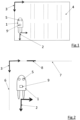
- the markings 6 and 7 are wall surfaces of a warehouse, the global positions of which are known in the reference coordinate system 3 and which are detected by the sensors 5 of the industrial truck 1 .
- the marking 8 is a sign, for example an emergency exit sign, which is set up at a known global position of the reference coordinate system 3 and is also detected by the sensor system 5 .
- the reference coordinate system 3 is determined by evaluating the sensor data in the data processing device 9 of the industrial truck 1 .
- the vehicle coordinate system 2 is compared with the reference coordinate system 3 so that the global localization of the industrial truck 1 in the working environment is made possible in the data processing device 9 .
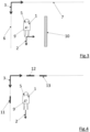
- the figure 3 shows an alternative representation of natural markings 6, 7, 10 for determining reference coordinates.
- the markings 6 and 7 are in turn wall surfaces of a warehouse, the global positions of which are known in the reference coordinate system 3 and which are detected by the sensors 5 of the industrial truck 1 .
- a shelf or shelf supports of a shelf is used as a marking 10 , the global position of which in the warehouse 4 and thus in the reference coordinate system 3 is also known and which is detected by the sensor system 5 of the industrial truck 1 .
- the arrangement corresponds to figure 3 the figure 2 .
- the marks 11, 12, 13 included QR codes, which can be read by the sensor system 5 of the industrial truck 1, which is in particular designed as a camera.
- the QR codes contain information about the global positions of the markings 11, 12, 13 in the reference coordinate system 3.
- the markings 11, 12, 13 and their information about the global positions in the reference coordinate system 3 are recorded by the sensors 5 of the industrial truck 1.
Landscapes
- Engineering & Computer Science (AREA)
- Radar, Positioning & Navigation (AREA)
- Remote Sensing (AREA)
- Physics & Mathematics (AREA)
- Transportation (AREA)
- General Physics & Mathematics (AREA)
- Automation & Control Theory (AREA)
- Structural Engineering (AREA)
- Civil Engineering (AREA)
- Life Sciences & Earth Sciences (AREA)
- Geology (AREA)
- Mechanical Engineering (AREA)
- Aviation & Aerospace Engineering (AREA)
- Electromagnetism (AREA)
- Control Of Position, Course, Altitude, Or Attitude Of Moving Bodies (AREA)
Abstract
Die Erfindung betrifft ein Verfahren zur Navigation eines Flurförderzeugs (1) mit einer Sensorik (5) zur Erkennung von Informationen im Betriebsbereich des Flurförderzeugs (1) und einer Datenverarbeitungseinrichtung (9) zur Auswertung dieser Informationen und Erstellung von Navigationsanweisungen und/oder Steuerungsbefehlen zur Navigation des Flurförderzeugs (1), wobei ausgehend von einer Erkundungsfahrt zunächst in der Datenverarbeitungseinrichtung (9) eine Umgebungskarte in einem Fahrzeugkoordinatensystem (2) mit Hilfe der Sensorik (5) erstellt wird und bei einer späteren Navigationsfahrt eine von der Sensorik (5) aktuell aufgenommene Szene in der Datenverarbeitungseinrichtung (9) mit der Umgebungskarte verglichen wird und eine Lokalisierung des Flurförderzeugs (1) im Fahrzeugkoordinatensystem (2) durchgeführt wird. Es wird vorgeschlagen, dass mindestens eine Markierung (6, 7, 8, 10, 11, 12, 13) mit bekannter globaler Position im Betriebsbereich des Flurförderzeugs (1) mittels der Sensorik (5) erfasst wird, und durch Auswertung der Sensordaten in der Datenverarbeitungseinrichtung (9) ein Referenzkoordinatensystem (3) festgelegt wird, und die im Fahrzeugkoordinatensystem (2) erstellte Umgebungskarte in der Datenverarbeitungseinrichtung (9) mit dem Referenzkoordinatensystem (3) abgeglichen wird, und die Lokalisierung des Flurförderzeugs (1) im Fahrzeugkoordinatensystem (2) in der Datenverarbeitungseinrichtung (9) in eine Lokalisierung des Flurförderzeugs (1) im Referenzkoordinatensystem (3) überführt wird.The invention relates to a method for navigating an industrial truck (1) with a sensor system (5) for detecting information in the operating range of the industrial truck (1) and a data processing device (9) for evaluating this information and creating navigation instructions and/or control commands for navigating the Industrial truck (1), whereby, starting from an exploratory trip, a map of the surroundings is first created in the data processing device (9) in a vehicle coordinate system (2) with the help of the sensor system (5), and during a later navigation trip a scene currently recorded by the sensor system (5) is created in the data processing device (9) is compared with the surrounding map and the industrial truck (1) is localized in the vehicle coordinate system (2). It is proposed that at least one marking (6, 7, 8, 10, 11, 12, 13) with a known global position in the operating range of the industrial truck (1) is detected by means of the sensor system (5), and by evaluating the sensor data in the A reference coordinate system (3) is determined in the data processing device (9), and the environment map created in the vehicle coordinate system (2) is compared with the reference coordinate system (3) in the data processing device (9), and the location of the industrial truck (1) in the vehicle coordinate system (2). the data processing device (9) is converted into a localization of the industrial truck (1) in the reference coordinate system (3).
Description
Die Erfindung betrifft ein Verfahren zur Navigation eines Flurförderzeugs, insbesondere eines autonomen oder automatisierten Flurförderzeugs, mit einer Sensorik zur Erkennung von Informationen im Betriebsbereich des Flurförderzeugs und einer Datenverarbeitungseinrichtung zur Auswertung dieser Informationen und Erstellung von Navigationsanweisungen und/oder Steuerungsbefehlen zur Navigation des Flurförderzeugs, wobei ausgehend von einer Erkundungsfahrt zunächst in der Datenverarbeitungseinrichtung eine Umgebungskarte in einem Fahrzeugkoordinatensystem mit Hilfe der Sensorik erstellt wird und bei einer späteren Navigationsfahrt eine von der Sensorik aktuell aufgenommene Szene in der Datenverarbeitungseinrichtung mit der Umgebungskarte verglichen wird und eine Lokalisierung des Flurförderzeugs im Fahrzeugkoordinatensystem durchgeführt wird.The invention relates to a method for navigating an industrial truck, in particular an autonomous or automated industrial truck, with a sensor system for detecting information in the operating area of the industrial truck and a data processing device for evaluating this information and creating navigation instructions and/or control commands for navigating the industrial truck, with the starting point from a reconnaissance trip, a map of the surroundings is first created in the data processing device in a vehicle coordinate system with the help of the sensors and during a subsequent navigation trip, a scene currently recorded by the sensors is compared in the data processing device with the map of the surroundings and the industrial truck is localized in the vehicle coordinate system.
Außerdem betrifft die Erfindung ein System zur Durchführung des Verfahrens.The invention also relates to a system for carrying out the method.
Beim Betrieb von Flurförderzeugen kommen vermehrt Navigationssysteme zum Einsatz, die einen automatisierten oder teilautomatisierten Betrieb eines Flurförderzeugs ermöglichen sollen. Da Flurförderzeuge meistens in definierten Betriebsbereichen, zum Beispiel in Warenlagern, eingesetzt werden, können hierfür ortsbezogene Navigationssysteme genutzt werden. Dabei werden im Warenlager beispielsweise Zeichen, Linien und Schilder oder auch Barcodes und Funkstationen zur Übermittlung von Identifikationssignalen (Funkbeacons) angebracht. Diese Informationen sind aber nur abrufbar, wenn sie in ein Managementsystem für den Betrieb des Flurförderzeugs eingetragen werden. Das Flurförderzeug kann über einen Sensor, zum Beispiel einem optischen Sensor, diese Informationen erfassen und mittels einer Datenverarbeitungseinrichtung mit den Eintragungen im Managementsystem vergleichen. Auf diese Weise ist eine erleichterte manuelle oder automatische Navigation des Flurförderzeugs im Warenlager möglich.When operating industrial trucks, navigation systems are increasingly being used, which are intended to enable automated or partially automated operation of an industrial truck. Since industrial trucks are mostly used in defined operating areas, for example in warehouses, location-based navigation systems can be used for this. For example, signs, lines and signs or also barcodes and radio stations for the transmission of identification signals (radio beacons) are attached in the warehouse. However, this information can only be called up if it is entered into a management system for operating the industrial truck. The industrial truck can use a sensor, for example an optical sensor, to record this information and use a data processing device to compare it with the entries in the management system. In this way, easier manual or automatic navigation of the industrial truck in the warehouse is possible.
Es sind auch schon Methoden vorgeschlagen worden, mit denen sich ein autonomes oder automatisiertes Flurförderzeug selbst in unbekannten Umgebungen lokalisieren kann. Hierzu gehört die sogenannte SLAM-Methode, die seit einigen Jahren in der Robotik verwendet wird. "SLAM" ist die englische Abkürzung für "Simultaneous Localization and Mapping". Hierbei wird ausgehend von einer Erkundungsfahrt des Flurförderzeugs im Betriebsbereich zunächst eine Umgebungskarte mit Hilfe der genutzten Sensorik am Roboter, die zum Beispiel Kameras, Laserscanner und Ultraschallsensoren umfassen kann, erstellt. Kommt das autonome oder automatisierte Flurförderzeug an einer Position entlang, die das Flurförderzeug schon kartografiert hat, kann das Flurförderzeug sich mittels seiner Karte und der Messwerte der Sensorik lokalisieren. Dabei findet auch ein Update der Karte statt, falls sich die von der Sensorik aufgenommene Szene von der Karte unterscheidet. Dies kann zum Beispiel der Fall sein, wenn Paletten oder Fahrzeuge ihre zuvor kartografierte Position verändert haben.Methods have already been proposed with which an autonomous or automated industrial truck can locate itself in unfamiliar surroundings can. This includes the so-called SLAM method, which has been used in robotics for several years. "SLAM" is the English abbreviation for "Simultaneous Localization and Mapping". Based on a reconnaissance trip of the industrial truck in the operating area, a map of the environment is first created with the help of the sensors used on the robot, which can include cameras, laser scanners and ultrasonic sensors, for example. If the autonomous or automated industrial truck comes to a position that the industrial truck has already mapped, the industrial truck can localize itself using its map and the measured values of the sensors. The map is also updated if the scene recorded by the sensors differs from the map. This can be the case, for example, when pallets or vehicles have changed their previously mapped position.
Begonnen hat die SLAM-Methode mit Lasersensorik und wurde dann in den Jahren erweitert auf andere Sensoriken, wie zum Beispiel 2D- und 3D-Kameras, Inertial Measurement Units (IMUs), Ultraschallsensoren etc..The SLAM method started with laser sensors and was then expanded over the years to include other sensors, such as 2D and 3D cameras, inertial measurement units (IMUs), ultrasonic sensors, etc.
Der Nachteil der SLAM-Methode besteht darin, dass bei Initialisierung des autonomen oder automatisierten Flurförderzeugs die aktuelle Fahrzeugposition als Ursprung, also mit einer Pose bezüglich der Raumachsen x = y = z = 0 und bezüglich der Raumwinkel phi = psi = rho = 0, angenommen wird, ohne einen Bezug zur Umgebung oder zu anderen Fahrzeugen herzustellen.The disadvantage of the SLAM method is that when the autonomous or automated industrial truck is initialized, the current vehicle position is assumed to be the origin, i.e. with a pose in relation to the spatial axes x = y = z = 0 and in relation to the spatial angles phi = psi = rho = 0 without making any reference to the surroundings or to other vehicles.
Das Problem, dass sich mehrere autonome oder automatisierte Flurförderzeuge eine gemeinsame Karte teilen und sich über ein Referenzkoordinatensystem austauschen, wurde von der Wissenschaft unter dem Stichwort Multi-Vehicle-SLAM (MVSLAM) gelöst. Auch wenn hier die einzelnen autonomen oder automatisierten Flurförderzeuge sich zu einem Referenzsystem einigen, fehlt ihnen der Bezug zur Umgebung. Es fehlt also ein Referenzsystem, das auch die Umgebung, zum Beispiel eine Lagerhalle, nutzt, um beispielsweise Regalpositionen und ähnliches anzugeben.The problem that several autonomous or automated industrial trucks share a common map and exchange information about a reference coordinate system was solved by science under the keyword Multi-Vehicle-SLAM (MVSLAM). Even if the individual autonomous or automated industrial trucks agree on a reference system, they lack the connection to the environment. So there is no reference system that also uses the environment, for example a warehouse, to specify shelf positions and the like, for example.
Die Grundlagen der SLAM-Methode sind in der folgenden Fachliteratur beschrieben:
- (1)
D. Moratuwage, B. Vo and D. Wang, "A hierarchical approach to the Multi-Vehicle-SLAM-Problem", 2012 15 th International Conference on Information Fusion, Singapore, 2012, pp. 1119-1125 - (2)
F. Zhang, H. Stähle, G. Chen, C. Buckl and A. Knoll, "Multiple vehicle cooperative localization under random finite set framework", 2013 IEEE/RSJ International Conference on Intelligent Robots and Systems, Tokyo, 2013, pp. 1405-1411 - (3)
D. Moratuwage, B. Vo and D. Wang, "Collaborative multi-vehicle SLAM with moving object tracking", 2013 IEEE International Conference on Robotics and Automation, Karlsruhe, 2013, pp. 5702-5708
- (1)
D. Moratuwage, B. Vo and D. Wang, "A hierarchical approach to the Multi-Vehicle-SLAM-Problem", 2012 15th International Conference on Information Fusion, Singapore, 2012, pp. 1119-1125 - (2)
F Zhang, H Stähle, G Chen, C Buckl and A Knoll, "Multiple vehicle cooperative localization under random finite set framework", 2013 IEEE/RSJ International Conference on Intelligent Robots and Systems, Tokyo, 2013, pp. 1405-1411 - (3)
D. Moratuwage, B. Vo and D. Wang, "Collaborative multi-vehicle SLAM with moving object tracking", 2013 IEEE International Conference on Robotics and Automation, Karlsruhe, 2013, pp. 5702-5708
Der vorliegenden Erfindung liegt die Aufgabe zugrunde, ein Verfahren der genannten Art sowie ein System zur Durchführung des Verfahrens so auszugestalten, dass eine verbesserte Lokalisierung des Flurförderzeugs ermöglicht wird.The present invention is based on the object of designing a method of the type mentioned and a system for carrying out the method in such a way that improved localization of the industrial truck is made possible.
Diese Aufgabe wird verfahrensseitig erfindungsgemäß dadurch gelöst, dass mindestens eine Markierung mit bekannter globaler Position im Betriebsbereich des Flurförderzeugs mittels der Sensorik erfasst wird, und durch Auswertung der Sensordaten in der Datenverarbeitungseinrichtung ein Referenzkoordinatensystem festgelegt wird, und die im Fahrzeugkoordinatensystem erstellte Umgebungskarte in der Datenverarbeitungseinrichtung mit dem Referenzkoordinatensystem abgeglichen wird, und die Lokalisierung des Flurförderzeugs im Fahrzeugkoordinatensystem in der Datenverarbeitungseinrichtung in eine Lokalisierung des Flurförderzeugs im Referenzkoordinatensystem überführt wird.In terms of the method, this object is achieved according to the invention in that at least one marking with a known global position in the operating area of the industrial truck is detected by the sensor system, and a reference coordinate system is defined by evaluating the sensor data in the data processing device, and the map of the surroundings created in the vehicle coordinate system is compared in the data processing device with the Reference coordinate system is compared, and the localization of the truck in the vehicle coordinate system in the data processing device is converted into a localization of the truck in the reference coordinate system.
Dabei liegt der Erfindung die Überlegung zu Grunde, dass durch Festlegung eines Referenzkoordinatensystems ein Bezug zwischen dem mit der SLAM-Methode oder einem anderen Kartierungsverfahren mittels der Sensorik des Flurförderzeugs aufgenommenen Umgebungskarte und der tatsächlichen Betriebsumgebung des autonomen oder automatisierten Flurförderzeugs hergestellt werden kann. Dadurch wird ein Verständnis des autonomen oder automatisierten Flurförderzeugs darüber erzeugt, wo es sich in der eigenen erstellten Umgebungskarte und in der globalen Arbeitsumgebung befindet. Dies ermöglicht zugleich ein Abgleichen von Umgebungskarten verschiedener Flurförderzeuge.The invention is based on the idea that by defining a reference coordinate system, a relationship can be established between the map of the surroundings recorded using the SLAM method or another mapping method using the sensors of the industrial truck and the actual operating environment of the autonomous or automated industrial truck. This creates an understanding of the autonomous or automated industrial truck about where it is in the environment map it has created and in the global work environment. At the same time, this makes it possible to compare maps of the surroundings of different industrial trucks.
In einer vorteilhaften Ausgestaltung wird eine Markierung verwendet, deren dreidimensionale Pose, insbesondere deren translatorische Position in den drei Raumachsen x, y und z sowie deren räumliche Orientierung durch Raumwinkel-Drehungen um die drei Raumachsen, bekannt ist. In diesem Fall genügt eine einzige Markierung, um ein Referenzkoordinatensystem festzulegen.In an advantageous embodiment, a marking is used whose three-dimensional pose, in particular its translational position in the three spatial axes x, y and z and its spatial orientation through solid angle rotations about the three spatial axes, is known. In this case, a single mark is sufficient to define a reference coordinate system.
Da in realen Anwendungen die Raumwinkelinformationen in der Regel nicht bekannt sind, sieht eine bevorzugte Weiterbildung der Erfindung vor, dass mindestens zwei Markierungen verwendet werden, deren translatorische Positionen in den drei Raumachsen x, y und z bekannt sind.Since the solid angle information is generally not known in real applications, a preferred development of the invention provides that at least two markings are used whose translatory positions in the three spatial axes x, y and z are known.
Zweckmäßigerweise wird als Markierung eine natürliche Markierung im Betriebsbereich des Flurförderzeugs, insbesondere ein Infrastrukturelement, zum Beispiel ein Schild, eine Regalstütze oder eine Wand, verwendet. Wichtig ist dabei eine eindeutige Zuordnung. Gibt es mehrere dieser natürlichen Markierungen mit ähnlicher Anordnung im Raum, sind diese als natürliche Markierung nicht geeignet.A natural marking in the operating area of the industrial truck, in particular an infrastructure element, for example a sign, a shelf support or a wall, is expediently used as the marking. A clear assignment is important. If there are several of these natural markings with a similar arrangement in space, these are not suitable as natural markings.
Zusätzlich oder alternativ kann als Markierung auch eine künstliche Markierung, insbesondere ein Reflektor, ein QR-Code oder ein Aruco-Marker, verwendet werden. Derartige künstliche Markierungen können zudem die Eindeutigkeit erhöhen, da sie so in der Umgebung nicht natürlich vorkommen.Additionally or alternatively, an artificial marking, in particular a reflector, a QR code or an Aruco marker, can also be used as a marking. Such artificial markings can also increase the uniqueness, since they do not occur naturally in the environment.
Bei den beiden genannten Markierungsverfahren unter Nutzung von natürlichen oder künstlichen Markierungen ist es von Vorteil, wenn dem, beispielsweise auf der SLAM-Methode basierenden, Kartierungsverfahren mitgeteilt wird, auf welche Markierung das Referenzkoordinatensystem gelegt wird und wie sich dieses zu der Markierung verhält.In the two above-mentioned marking methods using natural or artificial markings, it is advantageous if the mapping method, for example based on the SLAM method, is informed of which marking the reference coordinate system is placed on and how this relates to the marking.
Gemäß einer besonders bevorzugten Weiterbildung des Erfindungsgedankens wird mindestens eine Markierung verwendet, die maschinenlesbare Informationen, insbesondere Codes, zu ihrer globalen Position enthält, welche mittels der Sensorik abgerufen und in der Datenverarbeitungseinrichtung ausgewertet werden, um die im Fahrzeugkoordinatensystem erstellte Umgebungskarte mit dem Referenzkoordinatensystem abzugleichen.According to a particularly preferred development of the idea of the invention, at least one marking is used that contains machine-readable information, in particular codes, about its global position, which is retrieved using the sensors and evaluated in the data processing device in order to compare the map of the surroundings created in the vehicle coordinate system with the reference coordinate system.
Für die Sensorik wird vorzugsweise eine optische Sensorik verwendet, die insbesondere eine 2D- oder 3D-Kamera umfasst. Mit der optischen Sensorik können die Markierungen und deren gegebenenfalls vorhandenen maschinenlesbaren Informationen einfach erfasst werden.An optical sensor system, which in particular includes a 2D or 3D camera, is preferably used for the sensor system. With the optical sensors, the markings and any machine-readable information that may be present can be easily recorded.
Außerdem ist es zur Erhöhung der Robustheit des Verfahrens von Vorteil, wenn eine größere Anzahl von für das Flurförderzeug gut sichtbaren Markierungen im Betriebsbereich des Flurförderzeugs, zum Beispiel in einer Lagerhalle, platziert sind.In addition, to increase the robustness of the method, it is advantageous if a larger number of markings that are easily visible to the industrial truck are placed in the operating area of the industrial truck, for example in a warehouse.
Die Codes der Markierungen enthalten die globale Position in den drei Raumachsen x, y und z, wobei für die Fahrzeuglokalisierung in der Regel nur zwei Raumachsen x und y benötigt werden. Dies hat zudem den Vorteil, dass sich das Flurförderzeug immer wieder erneut referenzieren kann und einen erneuten Abgleich seiner Pose zur Referenzpose der Markierungen machen kann.The codes of the markings contain the global position in the three spatial axes x, y and z, with vehicle localization usually only requiring two spatial axes x and y. This also has the advantage that the industrial truck can reference itself again and again and can make a renewed comparison of its pose to the reference pose of the markings.
Ein entscheidender Vorteil der Erfindung besteht auch darin, dass durch den Einsatz weniger Markierungen, die über den gesamten Einsatzraum des Flurförderzeugs verteilt sind, Skalierungsfehler, die bei herkömmlichen visuellen SLAM-Verfahren (LDSO, ORB-SLAM, etc.) entstehen, korrigiert werden können. Dadurch kann gewährleistet werden, dass auch selbst erlernte, beispielsweise geteachte Umgebungskarten dauerhaft global korrekt bleiben, so dass auf künstlicher Basis, zum Beispiel mittels CAD-Tool etc., erzeugte Positionsinformationen überlagerter Systeme, wie zum Beispiel für das Warenmanagement, verwendet werden können. Die geteachten Umgebungskarten heutiger SLAM-basierter Systeme, müssen händisch korrigiert werden. Anfahrpositionen können nicht aus künstlich erzeugten Positionen abgeleitet werden, sondern müssen ebenfalls aufwändig geteacht werden. Derartige unattraktive Nachbearbeitungsschritte können mit der Erfindung insofern entfallen.A decisive advantage of the invention is that the use of fewer markings, which are distributed over the entire operational area of the industrial truck, can correct scaling errors that occur with conventional visual SLAM methods (LDSO, ORB-SLAM, etc.). . This can ensure that self-learned, for example taught, environment maps remain permanently globally correct, so that position information generated on an artificial basis, for example using a CAD tool etc., can be used for higher-level systems, such as for goods management. The taught environment maps of today's SLAM-based systems have to be corrected manually. Approach positions cannot be derived from artificially generated positions, but must also be taught in a complex manner. Such unattractive post-processing steps can be omitted with the invention.
In einer technisch einfachen Variante der Erfindung ist vorgesehen, dass die Umgebungskarte von einer Anzeigeeinrichtung, zum Beispiel einem am Flurförderzeug verbauten Display oder einem Smartphone, angezeigt wird und eine Bedienperson interaktiv das Referenzkoordinatensystem an der Anzeigevorrichtung setzen kann.In a technically simple variant of the invention, it is provided that the map of the surroundings is displayed by a display device, for example a display installed on the industrial truck or a smartphone, and an operator can interactively set the reference coordinate system on the display device.
Die Aufgabe wird ebenfalls durch Verfahren zur Erstellen einer Karte mit einer Sensorik zur Erkennung von Informationen im Betriebsbereich eines Flurförderzeugs gelöst, wobei ausgehend von einer Erkundungsfahrt zunächst in einer Datenverarbeitungseinrichtung eine Umgebungskarte in einem Fahrzeugkoordinatensystem mit Hilfe der Sensorik erstellt wird, und die Umgebungskarte mit einem Referenzkoordinatensystem des Betriebsbereichs abgeglichen wird, indem die Umgebungskarte mit einer CAD-Karte des Betriebsbereichs abgeglichen wird.The object is also achieved by a method for creating a map with a sensor system for detecting information in the operating area of an industrial truck, based on a reconnaissance trip, a map of the surroundings is first created in a data processing device in a vehicle coordinate system with the aid of sensors, and the map of the surroundings is compared with a reference coordinate system of the operating area by comparing the map of the surroundings with a CAD map of the operating area.
Die Umgebungskarte wird insbesondere derart mit der CAD-Karte des Betriebsbereichs abgeglichen, dass die Umgebungskarte deckungsgleich mit der CAD-Karte ist.In particular, the map of the surroundings is compared with the CAD map of the operating area in such a way that the map of the surroundings is congruent with the CAD map.
Die mittels der Sensorik, beispielsweise anhand der SLAM-Methode, erstelle Umgebungskarte im Fahrzeugkoordinatensystem kann hierzu insbesondere in ein Computerprogramm exportiert werden, das bevorzugt auf einer Datenverarbeitungsvorrichtung abläuft. In das Computerprogramm wird weiterhin eine das Referenzkoordinatensystem definierende CAD-Karte des Betriebsbereich geladen. In dem Computerprogramm wird die mittels der Sensorik erstelle Umgebungskarte über die CAD-Karte gelegt und die Umgebungskarte mit der CAD-Karte des Betriebsbereichs derart abgeglichen, dass die Umgebungskarte deckungsgleich mit der CAD-Karte ist. Dieser Abgleich kann automatisiert von dem Computerprogramm durchgeführt werden, indem dieses soweit optimiert, dass die Karten möglichst gut zusammenpassen. Alternativ oder zusätzlich kann ein Bediener händisch die mittels der Sensorik erstellte Umgebungskarte derart verschieben, dass die Umgebungskarte mit der CAD-Karte deckungsgleich ist. Noch bestehende Abweichungen können von dem Computerprogramm optimiert werden. Die Verschiebung bzw. der Offset der Umgebungskarte kann anschließend in eine Datenverarbeitungseinrichtung des Flurförderzeugs exportiert werden, so dass die im Fahrzeugkoordinatensystem erstellte Umgebungskarte und das Referenzkoordinatensystem übereinander liegen.For this purpose, the environment map in the vehicle coordinate system created by means of the sensor system, for example using the SLAM method, can be exported in particular to a computer program which preferably runs on a data processing device. A CAD map of the operating area defining the reference coordinate system is also loaded into the computer program. In the computer program, the map of the environment created by the sensors is placed over the CAD map and the map of the environment is compared with the CAD map of the operating area in such a way that the map of the environment is congruent with the CAD map. This comparison can be carried out automatically by the computer program by optimizing it so that the cards fit together as well as possible. Alternatively or additionally, an operator can manually move the map of the surroundings created by the sensor system in such a way that the map of the surroundings is congruent with the CAD map. Existing deviations can be optimized by the computer program. The displacement or the offset of the map of the surroundings can then be exported to a data processing device of the industrial truck, so that the map of the surroundings created in the vehicle coordinate system and the reference coordinate system are superimposed.
Die Erfindung betrifft ferner ein System zur Durchführung des Verfahrens zur Navigation eines Flurförderzeugs mit einer am Flurförderzeug angeordneten Sensorik zur Erkennung von Informationen im Betriebsbereich des Flurförderzeugs und einer Datenverarbeitungseinrichtung zur Auswertung dieser Informationen und Erstellung von Navigationsanweisungen und/oder Steuerungsbefehlen zur Navigation des Flurförderzeugs, wobei die Datenverarbeitungseinrichtung dazu eingerichtet ist, aus Sensordaten einer Erkundungsfahrt eine Umgebungskarte in einem Fahrzeugkoordinatensystem zu erstellen und aus Sensordaten einer Navigationsfahrt eine Lokalisierung des Flurförderzeugs in der Umgebungskarte durchzuführen.The invention also relates to a system for carrying out the method for navigating an industrial truck with sensors arranged on the industrial truck for detecting information in the operating area of the industrial truck and a data processing device for evaluating this information and creating navigation instructions and/or control commands for navigating the industrial truck, the Data processing device is set up from Sensor data of a reconnaissance trip to create a map of the surroundings in a vehicle coordinate system and to carry out a localization of the industrial truck in the map of the surroundings from sensor data of a navigation trip.
Bei dem System wird die gestellte Aufgabe erfindungsgemäß dadurch gelöst, dass mindestens eine Markierung mit bekannter globaler Position im Betriebsbereich des Flurförderzeugs vorgesehen ist, die durch die Sensorik detektierbar ist, und die Datenverarbeitungseinrichtung dazu eingerichtet ist, aufgrund der bekannten Position der Markierung ein Referenzkoordinatensystem festzulegen und die im Fahrzeugkoordinatensystem erstellte Umgebungskarte mit dem Referenzkoordinatensystem abzugleichen und die Lokalisierung des Flurförderzeugs im Fahrzeugkoordinatensystem in eine Lokalisierung des Flurförderzeugs im Referenzkoordinatensystem zu überführen.In the system, the stated object is achieved according to the invention in that at least one marker with a known global position is provided in the operating area of the industrial truck, which can be detected by the sensors, and the data processing device is set up to define a reference coordinate system based on the known position of the marker and to compare the area map created in the vehicle coordinate system with the reference coordinate system and to convert the localization of the industrial truck in the vehicle coordinate system into a localization of the industrial truck in the reference coordinate system.
Die Erfindung bietet eine ganze Reihe von Vorteilen:
Das erfindungsgemäße Verfahren senkt den Aufwand zur Einrichtung eines Navigationssystems eines autonomen oder automatisierten Flurförderzeugs für das Bedienpersonal vor Ort oder einen Servicetechniker, der dies als Serviceleistung mit anbieten kann. Aktuell ist eine manuelle Kalibrierung des Navigationssystems eines autonomen oder automatisierten Flurförderzeugs nur durch spezialisiertes Fachpersonal möglich. Mit der Erfindung wird eine automatische Einrichtung durch das Flurförderzeug selbst ermöglicht.The invention offers a whole range of advantages:
The method according to the invention reduces the outlay for setting up a navigation system of an autonomous or automated industrial truck for the operating personnel on site or for a service technician who can also offer this as a service. Manual calibration of the navigation system of an autonomous or automated industrial truck is currently only possible by specialized personnel. With the invention, an automatic device is made possible by the industrial truck itself.
Der Vorteil ist zudem, dass ein bestehendes Referenzkoordinatensystem, das zum Beispiel für ein betreiberseitiges Managementsoftwaresystem verwendet wird, nicht für jedes Flurförderzeug abgeändert werden muss. Es genügt ein Referenzkoordinatensystem, das eine Lokalisierung der Flurförderzeuge innerhalb einer Umgebung ermöglicht und somit die Ausführung von Aufträgen erlaubt. Dadurch können ohne großen Einrichtungsaufwand die Flurförderzeuge beauftragt werden. Zudem haben alle in einem Betriebsbereich vorhandenen autonomen oder automatisierten Flurförderzeuge ein gemeinsames Referenzkoordinatensystem und können somit miteinander besser agieren.Another advantage is that an existing reference coordinate system, which is used for example for an operator-side management software system, does not have to be modified for each industrial truck. A reference coordinate system is sufficient that enables the industrial trucks to be localized within an environment and thus allows orders to be carried out. This means that the industrial trucks can be commissioned without a great deal of setup work. In addition, all autonomous or automated industrial trucks in an operating area have a common reference coordinate system and can therefore interact better with one another.
Weitere Vorteile und Einzelheiten der Erfindung werden anhand der in den schematischen Figuren dargestellten Ausführungsbeispiele näher erläutert. Hierbei zeigen
Figur 1- ein Prinzipbild für den Zusammenhang zwischen Fahrzeugkoordinatensystem und Referenzkoordinatensystem,
Figur 2- eine Darstellung natürlicher Markierungen zur Referenzkoordinatenbestimmung,
Figur 3- eine alternative Darstellung natürlicher Markierungen zur Referenzkoordinatenbestimmung und
Figur 4- eine Darstellung künstlicher Markierungen zur Referenzkoordinatenbestimmung.
- figure 1
- a basic diagram for the connection between the vehicle coordinate system and the reference coordinate system,
- figure 2
- a representation of natural markings for reference coordinate determination,
- figure 3
- an alternative representation of natural markings for reference coordinate determination and
- figure 4
- a representation of artificial markers for reference coordinate determination.
In den unterschiedlichen Figuren sind dieselben Merkmale mit denselben Bezugsziffern bezeichnet.The same features are denoted by the same reference numbers in the different figures.
In der
In der
Die
In der
Claims (9)
Applications Claiming Priority (1)
| Application Number | Priority Date | Filing Date | Title |
|---|---|---|---|
| DE102021130631.0A DE102021130631A1 (en) | 2021-11-23 | 2021-11-23 | Method and system for navigating an industrial truck |
Publications (2)
| Publication Number | Publication Date |
|---|---|
| EP4239428A2 true EP4239428A2 (en) | 2023-09-06 |
| EP4239428A3 EP4239428A3 (en) | 2024-01-24 |
Family
ID=83996422
Family Applications (1)
| Application Number | Title | Priority Date | Filing Date |
|---|---|---|---|
| EP22203506.5A Pending EP4239428A3 (en) | 2021-11-23 | 2022-10-25 | Method and system for navigating an industrial truck |
Country Status (2)
| Country | Link |
|---|---|
| EP (1) | EP4239428A3 (en) |
| DE (1) | DE102021130631A1 (en) |
Family Cites Families (4)
| Publication number | Priority date | Publication date | Assignee | Title |
|---|---|---|---|---|
| KR20120108277A (en) * | 2011-03-23 | 2012-10-05 | (주)하기소닉 | Method for localizing intelligent mobile robot by using both natural landmark and artificial landmark |
| JP7139762B2 (en) * | 2018-07-31 | 2022-09-21 | カシオ計算機株式会社 | AUTONOMOUS MOBILE DEVICE, AUTONOMOUS MOVEMENT METHOD AND PROGRAM |
| JP7482453B2 (en) * | 2018-12-28 | 2024-05-14 | パナソニックIpマネジメント株式会社 | Positioning device and mobile object |
| DE102019217160A1 (en) * | 2019-11-07 | 2021-05-12 | Robert Bosch Gmbh | Computer-implemented method for creating a map of the area for the operation of a mobile agent |
-
2021
- 2021-11-23 DE DE102021130631.0A patent/DE102021130631A1/en active Pending
-
2022
- 2022-10-25 EP EP22203506.5A patent/EP4239428A3/en active Pending
Non-Patent Citations (3)
| Title |
|---|
| D. MORATUWAGEB. VOD. WANG: "A hierarchical approach to the Multi-Vehicle-SLAM-Problem", 15 TH INTERNATIONAL CONFERENCE ON INFORMATION FUSION, SINGAPORE, 2012, pages 1119 - 1125, XP032228543 |
| D. MORATUWAGEB. VOD. WANG: "Collaborative multi-vehicle SLAM with moving object tracking", 2013 IEEE INTERNATIONAL CONFERENCE ON ROBOTICS AND AUTOMATION, KARLSRUHE, 2013, pages 5702 - 5708, XP032506717, DOI: 10.1109/ICRA.2013.6631397 |
| F. ZHANGH. STÄHLEG. CHENC. BUCKLA. KNOLL: "Multiple vehicle cooperative localization under random finite set framework", 2013 IEEE/RSJ INTERNATIONAL CONFERENCE ON INTELLIGENT ROBOTS AND SYSTEMS, TOKYO, 2013, pages 1405 - 1411, XP032537661, DOI: 10.1109/IROS.2013.6696533 |
Also Published As
| Publication number | Publication date |
|---|---|
| DE102021130631A1 (en) | 2023-05-25 |
| EP4239428A3 (en) | 2024-01-24 |
Similar Documents
| Publication | Publication Date | Title |
|---|---|---|
| EP3105547B1 (en) | Method for determining the absolute position of a mobile unit, and mobile unit | |
| EP2526378B1 (en) | Method and system for sensing the position of a vehicle | |
| DE10234730A1 (en) | Position determination method for use with industrial trucks, e.g. forklift trucks, within a defined area, wherein the positions of transport and reference fixed objects are known and truck positions are determined from them | |
| DE102011082478A1 (en) | Method, system and device for locating a vehicle relative to a predefined reference system | |
| EP2824525B1 (en) | Method and device for determining the position of resources of an industrial automation assembly | |
| EP1504279A2 (en) | Device for determining the position by means of fixed and/or variable landmarks | |
| EP3454158B1 (en) | Method and device for navigation of an industrial truck | |
| WO2020126240A1 (en) | Method for operating an automation technology field device in an augmented-reality/mixed-reality environment | |
| EP3977225B1 (en) | Method for creating an environment map for use in the autonomous navigation of a mobile robot | |
| EP4239428A2 (en) | Method and system for navigating an industrial truck | |
| DE102016222664A1 (en) | Method for installing a localization system | |
| EP3809228B1 (en) | Method for navigating an industrial truck | |
| DE102020213111A1 (en) | Method and system for determining a pose or position of a mobile device | |
| DE102021126879A1 (en) | DECENTRALIZED LOCATION SYSTEMS AND PROCEDURES | |
| DE102017220634B4 (en) | Arrangement and procedure | |
| DE102019202733B4 (en) | Control unit for the navigation of an autonomous vehicle | |
| DE102016222156A1 (en) | Method and control unit for controlling an autonomous transport vehicle | |
| EP4186651B1 (en) | System and method with a system | |
| DE102019220364A1 (en) | Calibration device and method for calibrating a device | |
| WO2023126115A1 (en) | Method and system for navigating mobile logistics robots | |
| DE102022111649A1 (en) | Attachment with a space detection device for recording by a driverless transport system and method for detecting object spaces | |
| DE102022111648A1 (en) | Attachment with a space detection device for recording by a driverless transport system and method for detecting object spaces | |
| DE102022207370A1 (en) | Method for detecting a faulty map of an environment | |
| DE102021207179A1 (en) | Method and system for determining a location of a vehicle | |
| EP3980724A1 (en) | Method for establishing a universally usable feature map |
Legal Events
| Date | Code | Title | Description |
|---|---|---|---|
| PUAI | Public reference made under article 153(3) epc to a published international application that has entered the european phase |
Free format text: ORIGINAL CODE: 0009012 |
|
| STAA | Information on the status of an ep patent application or granted ep patent |
Free format text: STATUS: THE APPLICATION HAS BEEN PUBLISHED |
|
| AK | Designated contracting states |
Kind code of ref document: A2 Designated state(s): AL AT BE BG CH CY CZ DE DK EE ES FI FR GB GR HR HU IE IS IT LI LT LU LV MC ME MK MT NL NO PL PT RO RS SE SI SK SM TR |
|
| PUAL | Search report despatched |
Free format text: ORIGINAL CODE: 0009013 |
|
| AK | Designated contracting states |
Kind code of ref document: A3 Designated state(s): AL AT BE BG CH CY CZ DE DK EE ES FI FR GB GR HR HU IE IS IT LI LT LU LV MC ME MK MT NL NO PL PT RO RS SE SI SK SM TR |
|
| RIC1 | Information provided on ipc code assigned before grant |
Ipc: B66F 9/06 20060101ALI20231221BHEP Ipc: B66F 9/075 20060101ALI20231221BHEP Ipc: G01C 21/20 20060101ALI20231221BHEP Ipc: G05D 1/02 20200101AFI20231221BHEP |