EP4219310A1 - Environmental control system including humidity sensor - Google Patents
Environmental control system including humidity sensor Download PDFInfo
- Publication number
- EP4219310A1 EP4219310A1 EP23153795.2A EP23153795A EP4219310A1 EP 4219310 A1 EP4219310 A1 EP 4219310A1 EP 23153795 A EP23153795 A EP 23153795A EP 4219310 A1 EP4219310 A1 EP 4219310A1
- Authority
- EP
- European Patent Office
- Prior art keywords
- turbine
- air
- heat exchanger
- humidity sensor
- exhaust
- Prior art date
- Legal status (The legal status is an assumption and is not a legal conclusion. Google has not performed a legal analysis and makes no representation as to the accuracy of the status listed.)
- Pending
Links
- 230000007613 environmental effect Effects 0.000 title claims abstract description 12
- 238000007791 dehumidification Methods 0.000 claims abstract description 43
- 239000012530 fluid Substances 0.000 claims abstract description 5
- 238000004891 communication Methods 0.000 claims abstract description 4
- XLYOFNOQVPJJNP-UHFFFAOYSA-N water Substances O XLYOFNOQVPJJNP-UHFFFAOYSA-N 0.000 claims description 30
- 238000011144 upstream manufacturing Methods 0.000 description 9
- 238000005259 measurement Methods 0.000 description 7
- 230000008901 benefit Effects 0.000 description 5
- 238000004458 analytical method Methods 0.000 description 3
- 238000000034 method Methods 0.000 description 3
- 238000000926 separation method Methods 0.000 description 3
- 230000000694 effects Effects 0.000 description 2
- 239000000284 extract Substances 0.000 description 2
- 238000012423 maintenance Methods 0.000 description 2
- 230000008569 process Effects 0.000 description 2
- 230000006835 compression Effects 0.000 description 1
- 238000007906 compression Methods 0.000 description 1
- 230000003247 decreasing effect Effects 0.000 description 1
- 238000001537 electron coincidence spectroscopy Methods 0.000 description 1
- 239000004744 fabric Substances 0.000 description 1
- 238000009434 installation Methods 0.000 description 1
- 239000000463 material Substances 0.000 description 1
- 239000003595 mist Substances 0.000 description 1
- 238000012986 modification Methods 0.000 description 1
- 230000004048 modification Effects 0.000 description 1
- 230000001681 protective effect Effects 0.000 description 1
- 230000009467 reduction Effects 0.000 description 1
- 238000012546 transfer Methods 0.000 description 1
Images
Classifications
-
- B—PERFORMING OPERATIONS; TRANSPORTING
- B64—AIRCRAFT; AVIATION; COSMONAUTICS
- B64D—EQUIPMENT FOR FITTING IN OR TO AIRCRAFT; FLIGHT SUITS; PARACHUTES; ARRANGEMENT OR MOUNTING OF POWER PLANTS OR PROPULSION TRANSMISSIONS IN AIRCRAFT
- B64D13/00—Arrangements or adaptations of air-treatment apparatus for aircraft crew or passengers, or freight space, or structural parts of the aircraft
- B64D13/06—Arrangements or adaptations of air-treatment apparatus for aircraft crew or passengers, or freight space, or structural parts of the aircraft the air being conditioned
- B64D2013/0603—Environmental Control Systems
- B64D2013/0648—Environmental Control Systems with energy recovery means, e.g. using turbines
-
- B—PERFORMING OPERATIONS; TRANSPORTING
- B64—AIRCRAFT; AVIATION; COSMONAUTICS
- B64D—EQUIPMENT FOR FITTING IN OR TO AIRCRAFT; FLIGHT SUITS; PARACHUTES; ARRANGEMENT OR MOUNTING OF POWER PLANTS OR PROPULSION TRANSMISSIONS IN AIRCRAFT
- B64D13/00—Arrangements or adaptations of air-treatment apparatus for aircraft crew or passengers, or freight space, or structural parts of the aircraft
- B64D13/06—Arrangements or adaptations of air-treatment apparatus for aircraft crew or passengers, or freight space, or structural parts of the aircraft the air being conditioned
- B64D2013/0603—Environmental Control Systems
- B64D2013/0662—Environmental Control Systems with humidity control
-
- Y—GENERAL TAGGING OF NEW TECHNOLOGICAL DEVELOPMENTS; GENERAL TAGGING OF CROSS-SECTIONAL TECHNOLOGIES SPANNING OVER SEVERAL SECTIONS OF THE IPC; TECHNICAL SUBJECTS COVERED BY FORMER USPC CROSS-REFERENCE ART COLLECTIONS [XRACs] AND DIGESTS
- Y02—TECHNOLOGIES OR APPLICATIONS FOR MITIGATION OR ADAPTATION AGAINST CLIMATE CHANGE
- Y02T—CLIMATE CHANGE MITIGATION TECHNOLOGIES RELATED TO TRANSPORTATION
- Y02T50/00—Aeronautics or air transport
- Y02T50/50—On board measures aiming to increase energy efficiency
Definitions
- Exemplary embodiments pertain to the art of environmental control systems and, in particular, to environmental control systems (ECS) that include a humidity sensor.
- ECS environmental control systems
- Water removal from, or dehumidification of, airflow is one of the primary functions of aircraft ECSs. Traditionally, the water removal has been done via a high pressure water collector or via low pressure water separation.
- water is separated using both high and low pressure separation. This can happen, for example, in systems that include two turbines.
- the system includes: a primary heat exchanger; a secondary heat exchanger; and an air cycle machine.
- the air cycle machine includes: a compressor fluidly coupled to an outlet of the primary heat exchanger and an inlet of the secondary heat exchanger; a dehumidification system arranged in fluid communication with the outlet of the secondary heat exchanger; a first turbine fluidly coupled to an outlet of the secondary heat exchanger; a second turbine disposed downstream of the first turbine that receives air from the first turbine in a normal mode; and a first humidity sensor disposed fluidly between the first turbine and the second turbine that measures humidity of air that has left the first turbine as it enters the second turbine in the normal mode.
- system can further include a second humidity sensor disposed fluidly between the secondary heat exchanger and the dehumidification system that measures humidity of air that has left the compressor before it enters the dehumidification system.
- the dehumidification system includes a condenser and a water extractor, and moisture is removed from air before entering the first turbine in the normal mode.
- system further includes a second humidity sensor disposed fluidly between the secondary heat exchanger and the dehumidification system that measures humidity of air that has left the compressor before it enters the dehumidification system.
- air exiting the first turbine passes through the condenser before entering the second turbine.
- the first humidity sensor includes an inlet and an exhaust, and/or the second turbine receives the air via a second turbine inlet, and/or the inlet is connected to the second turbine inlet such that air is directed from the second turbine inlet through the first humidity sensor to the exhaust.
- the exhaust is connected to an output of the second turbine.
- the exhaust is connected to an ambient environment.
- the exhaust includes an exhaust orifice disposed therein that controls a rate of flow through the first humidity sensor.
- the system can further include a bypass valve that diverts air around the dehumidification system such that air exiting the first turbine can enter the second turbine without passing though the dehumidification system when in a bypass mode.
- the first humidity sensor is downstream of the bypass valve.
- an environmental control system of an aircraft that includes an air cycle machine (ACM) with a first turbine but not the second.
- the environmental control system of this second embodiment includes: a primary heat exchanger; a secondary heat exchanger; and an air cycle machine.
- the ACM includes: a compressor fluidly coupled to an outlet of the primary heat exchanger and an inlet of the secondary heat exchanger; a dehumidification system arranged in fluid communication with the outlet of the secondary heat exchanger; a first turbine fluidly coupled to an outlet of the dehumidification system; and a humidity sensor disposed fluidly between second heat exchanger and the first turbine that measures humidity of air as it enters the first in the normal mode.
- the dehumidification system includes a condenser and a water extractor, and moisture is removed from air before entering the first turbine in the normal mode.
- the second system can further includes a second humidity sensor disposed fluidly between the secondary heat exchanger and the dehumidification system that measures humidity of air that has left the compressor before it enters the dehumidification system.
- the second system can have air exiting the first turbine pass through the condenser as it leaves the first turbine.
- the second system humidity sensor includes an inlet and an exhaust, and/or the first turbine receives the air via a first turbine inlet, and/or the inlet is connected to the first turbine inlet such that air is directed from the first turbine inlet through the first humidity sensor to the exhaust.
- the exhaust is connected to an output of the first turbine or to ambient.
- the exhaust in the second system includes an exhaust orifice disposed therein that controls a rate of flow through the first humidity sensor.
- the second system can further include a bypass valve that diverts air around the dehumidification system such that air exiting the secondary heat exchanger can enter the first turbine without passing though the dehumidification system when in a bypass mode.
- the first humidity sensor is downstream of the bypass valve.
- ECS 10 environmental control system
- the ECS 10 is supplied with, for example, bleed airflow 12 from a bleed air supply system 14 of a gas turbine engine.
- the environmental control system (ECS) 10 includes a RAM air circuit 11 including a shell or duct 13 within which one or more heat exchangers are located.
- the shell 13 can receive and direct a medium, such as ram air flow 18 for example, through a ram inlet 19.
- the one or more heat exchangers 16, 28 are devices built for efficient heat transfer from one medium to another.
- Examples of the type of heat exchangers that may be used include, but are not limited to, double pipe, shell and tube, plate, plate and shell, adiabatic shell, plate fin, pillow plate, and fluid heat exchangers.
- the bleed airflow 12 is input into a primary heat exchanger 16 of the ECS 10 where the bleed airflow 12 exchanges thermal energy with a RAM airflow 18, or alternatively ambient airflow.
- the bleed airflow is then directed through a compressor 20 of an air cycle machine 22.
- the compressor 20 and fan 24 are driven by, for example, turbine 30 that shares a common shaft 26 with the compressor 20 and fan 24.
- the compressed bleed airflow 21 is directed to a secondary heat exchanger 28 where the compressed bleed airflow is cooled by thermal energy exchange with the RAM airflow 18.
- the bleed airflow 12 is then directed towards an expansion device 30 connected to the shaft 26 for primary expansion.
- the system includes at least one expansion device 30.
- the expansion device 30 will also be referred to as a turbine or the first turbine herein.
- the turbine 30 a mechanical device that includes components for performing thermodynamic work on air that leaves the compressor 20 (e.g., extracts work from or applies work to the compressed air by raising and/or lowering pressure and by raising and/or lowering temperature) and is used to drive the shaft 26 and thereby drive the fan 24 and the compressor 20.
- the compressed air is passed through a dehumidification/water removal system 40.
- This system is described as being part of the ACM for simplicity, but it shall be understood that any system 40 connected to a ACM such as ACM 22 shall be considered part of the ACM whether integrated with the ACM or implemented as a separate unit. This is applicable to all embodiments herein.
- the dehumidification system 40 includes a condenser 42, an optional reheater, and a water collector 44.
- the condenser 42 is a particular type of heat exchanger and the water collector 44 is a mechanical device that performs a process of removing water from a medium.
- the water collector 44 is a high pressure water separator that removes moisture from a medium at a highest pressure within the environmental control system 10 (e.g., downstream of the compressor 20 and ram air heat exchanger 28).
- the dehumidification system 40 further includes a reheater 46.
- the reheater 46 is another type of heat exchanger configured to increase the temperature of the air as it passes there through.
- the reheater 46 may be arranged generally upstream from the condenser 42 such that compressed air exiting secondary heat exchange 28 flows through the reheater 46 and then the condenser 42 sequentially.
- the ECS 10 can also include a bypass or economy valve (ECV) 35.
- ECV 35 When the ECV 35 is open, the air output from the ram air heat exchanger 38 has a temperature and pressure sufficient to meet the demands of the one or more loads, such as the cabin 36 for example.
- ECV 35 when ECV 35 is open, the system is said to be operating in a bypass mode. Accordingly, all or at least a portion of air output from the ram air heat exchanger 28 is configured to bypass including the dehumidification system 40 but not the turbine 30 in order to drive the compressor 20.
- a humidity sensor 100 is provided upstream of the turbine 30. As illustrated, the humidity sensor 100 is directly upstream of the turbine 30 and downstream of the ECV 35. In one embodiment, this humidity sensor 100 is the only sensor in the ECS 10. In such an embodiment, the sensor 100 can be said to be in the "turbine inlet location.” Measuring humidity in such a position allows the ECS controls to minimize the risk of rotor icing effects in the turbine 30 (e.g. reduce ACM speed or raise turbine inlet temperature if required).
- the humidity sensor 100 (or any other humidity sensor herein, e.g., sensor 102 below) can be an integrated circuit (IC) sensor that can measure one or both temperature and pressure as well. This can simplify wiring in the system and may allow for a reduction in the number of separate sensors. More importantly, advanced ECV opening logic based on measured humidity can be utilized, further optimizing system performance. Also, knowing humidity values may help in root cause failure analyses for the ECS components.
- IC integrated circuit
- FIGs. 2A and 2B show two different installations that may be used when measuring humidity.
- the turbine 30 is shown as having an inlet pipe 200.
- the humidity sensor 100 can divert a small portion the air provided to the turbine 30 via an inlet and an outlet.
- the inlet is shown as measuring bypass channel 202.
- the bypass channel 202 passes through the sensor 100 providing air to the sensor for measurements.
- the rate of flow through the sensor can be controlled by an exhaust orifice 205 in the exhaust 204.
- the orifice can be fixed or adjustable.
- the exhaust 204 can exhaust the air to an ambient environment. This environment can be overboard or the cabin, for example.
- the sensor 100 can receive power and can also provide data (measurements) to an ECS controller 240.
- the turbine 30 is shown as having an inlet pipe 200.
- the humidity sensor 100 can divert a small portion the air provided to the turbine 30 via a measuring bypass channel 202.
- the bypass channel 202 passes through the sensor 100 providing air to the sensor for measurements.
- the sensor 100 can receive power and can also provide data (measurements) to an ECS controller 240.
- the rate of flow through the sensor can be controlled by an exhaust orifice 205 in the exhaust 204.
- the orifice can be fixed or adjustable.
- the exhaust 204 can be connected back to the outlet 207 of the turbine 30.
- an optional second humidity sensor 102 is shown upstream of the dehumidification system 40.
- having such a second sensor can provide one more advantages.
- having two sensors in addition to the above advantages of a single sensor) can allow for performance measurements of the dehumidification system 40 and may further provide additional information for a root cause failure analysis.
- the location of sensor 102 can also provide the benefit of more accurately determining if moisture is present in the system and therefore utilize the water removal system only when required.
- the ECS 10 can include a pair of expansion devices 30 and 32.
- the expansion devices 30, 32 of the system 10 may, but need not be substantially identical.
- the expansion devices are turbines.
- turbine 32 can be referred to as a second turbine.
- the first and second turbines 30, 32 are both connected to the shaft 26 and, as above, are mechanical device that include components for performing thermodynamic work on air that leaves the compressor 20 (e.g., extracts work from or applies work to the compressed air by raising and/or lowering pressure and by raising and/or lowering temperature) and is used to drive the shaft 26 and thereby drive the fan 24 and the compressor 20.
- components for performing thermodynamic work on air that leaves the compressor 20 e.g., extracts work from or applies work to the compressed air by raising and/or lowering pressure and by raising and/or lowering temperature
- the dehumidification system 40 includes a condenser 42, an optional reheater, and a water collector 44.
- the condenser 42 is a particular type of heat exchanger and the water collector 44 is a mechanical device that performs a process of removing water from a medium.
- the water collector 44 is a high-pressure water separator that removes moisture from a medium at a highest pressure within the environmental control system 10 (e.g., downstream of the compressor 20 and ram air heat exchanger 28).
- the dehumidification system 40 further includes a reheater 46.
- the reheater 46 is another type of heat exchanger configured to increase the temperature of the air as it passes there through.
- the reheater 46 may be arranged generally upstream from the condenser 42 such that compressed air exiting secondary heat exchange 28 flows through the reheater 46 and then the condenser 42 sequentially.
- the air is then directed to the first turbine 30 via a first inlet tube 200' for expansion. After expansion, the air it then again directed through the condenser 42 and then into the second turbine 32 via a second inlet tube 200".
- the expanded air from the second turbine 32 can be provided to the cabin 36.
- the ECS 10 can also include a bypass or economy valve (ECV) 35.
- ECV 35 When the ECV 35 is open, the air output from the ram air heat exchanger 28 has a temperature and pressure sufficient to meet the demands of the one or more loads, such as the cabin 36 for example. Accordingly, all or at least a portion of air output from the ram air heat exchanger 28 is configured to bypass including the dehumidification system 40 and the first turbine 30 but not the second turbine 32.
- the humidity sensor 100 is provided upstream of the second turbine 32. As illustrated, the humidity sensor 100 is directly upstream of the second turbine 32 in the second inlet tube 200" and downstream of the ECV 35. As above, the system of FIG. 3 can operate in normal and bypass modes based on the position of the ECV 35.
- this humidity sensor 100 is the only sensor in the ECS 10.
- the sensor 100 can be said to be in the "second turbine inlet location" on the second inlet tube 200". Measuring humidity in such a position allows the ECS controls to minimize the risk of rotor icing effects in the turbine 32 (e.g., reduce ACM speed if required).
- sensor 100 can be arranged relative to any of turbines herein as shown in FIGs. 2A and 2B .
- FIG. 3 only a single sensor has been shown discussed. It shall be understood that one or more optional additional sensors can be provided.
- an optional second humidity sensor 102 is shown upstream of the dehumidification system 40.
- having such a second sensor can provide one more advantages.
- having two sensors in addition to the above advantages of a single sensor) can allow for performance measurements of the dehumidification system 40 be used to assess when the dehumidification system is needed and may further provide additional information in support of a root cause failure analysis of a field issue.
- first sensor 100 could be moved such that it is in the first inlet tube 200' of the first turbine 30 rather than the second inlet tube 200" of the second turbine 32.
- the dehumidification system 40 can be monitored. For example, the difference in humidity upstream of the dehumidification system 40 measured by the second humidity sensor 102 can be compared to the humidity measured by the first humidity sensor 100. The difference will show the effectiveness of dehumidification system 40 at removing humidity. Further, the values can be tracked over time to see if the effectiveness of dehumidification system 40 at removing humidity is decreasing. Such a decrease may lead to determination that the dehumidification system 40 is failing or needs maintenance or both. Such data can also be used to determine a cause of a failure of the air cycle machine.
Landscapes
- Health & Medical Sciences (AREA)
- General Health & Medical Sciences (AREA)
- Pulmonology (AREA)
- Engineering & Computer Science (AREA)
- Aviation & Aerospace Engineering (AREA)
- Drying Of Gases (AREA)
Abstract
Description
- Exemplary embodiments pertain to the art of environmental control systems and, in particular, to environmental control systems (ECS) that include a humidity sensor.
- Water removal from, or dehumidification of, airflow is one of the primary functions of aircraft ECSs. Traditionally, the water removal has been done via a high pressure water collector or via low pressure water separation.
- In high pressure water collection, water is condensed out of the air by reducing temperature on the air while the air is in a high pressure condition, prior to any turbine expansion. Lowering temperature on the air is accomplished through heat exchangers typically known as a condenser and sometimes also a reheater, where the hot side is the hot, humid high pressure air and the cold side is the cold air that has been dehumidified and has undergone turbine expansion.
- In low pressure water separation, water is condensed via turbine expansion prior to the air exiting the pack. The water coming off the turbine is often a very fine mist with a very small droplet size that would be difficult to gather using centrifugal forces and inertia alone. Therefore, water is coalesced into larger droplets with a cloth mesh filter prior to the water collecting can. This mesh is more burdensome because it needs regular schedule maintenance and the size of the water collecting can is also substantially bigger in order to lower air velocities such that any free moisture can be efficiently collected.
- In some cases water is separated using both high and low pressure separation. This can happen, for example, in systems that include two turbines.
- The management of free water within an ECS is particularly challenging in that the current art protective controls must conservatively limit the modes of system operation thereby not fully utilizing the performance capabilities of the system.
- Disclosed is an environmental control system of an aircraft. The system includes: a primary heat exchanger; a secondary heat exchanger; and an air cycle machine. The air cycle machine includes: a compressor fluidly coupled to an outlet of the primary heat exchanger and an inlet of the secondary heat exchanger; a dehumidification system arranged in fluid communication with the outlet of the secondary heat exchanger; a first turbine fluidly coupled to an outlet of the secondary heat exchanger; a second turbine disposed downstream of the first turbine that receives air from the first turbine in a normal mode; and a first humidity sensor disposed fluidly between the first turbine and the second turbine that measures humidity of air that has left the first turbine as it enters the second turbine in the normal mode.
- In addition to one or more of the features described above, or as an alternative to any of the foregoing embodiments, the system can further include a second humidity sensor disposed fluidly between the secondary heat exchanger and the dehumidification system that measures humidity of air that has left the compressor before it enters the dehumidification system.
- In addition to one or more of the features described above, or as an alternative to any of the foregoing embodiments, the dehumidification system includes a condenser and a water extractor, and moisture is removed from air before entering the first turbine in the normal mode.
- In addition to one or more of the features described above, or as an alternative to any of the foregoing embodiments, the system further includes a second humidity sensor disposed fluidly between the secondary heat exchanger and the dehumidification system that measures humidity of air that has left the compressor before it enters the dehumidification system.
- In addition to one or more of the features described above, or as an alternative to any of the foregoing embodiments, air exiting the first turbine passes through the condenser before entering the second turbine.
- In addition to one or more of the features described above, or as an alternative to any of the foregoing embodiments, the first humidity sensor includes an inlet and an exhaust, and/or the second turbine receives the air via a second turbine inlet, and/or the inlet is connected to the second turbine inlet such that air is directed from the second turbine inlet through the first humidity sensor to the exhaust.
- In addition to one or more of the features described above, or as an alternative to any of the foregoing embodiments, the exhaust is connected to an output of the second turbine.
- In addition to one or more of the features described above, or as an alternative to any of the foregoing embodiments, the exhaust is connected to an ambient environment.
- In addition to one or more of the features described above, or as an alternative to any of the foregoing embodiments, the exhaust includes an exhaust orifice disposed therein that controls a rate of flow through the first humidity sensor.
- In addition to one or more of the features described above, or as an alternative to any of the foregoing embodiments, the system can further include a bypass valve that diverts air around the dehumidification system such that air exiting the first turbine can enter the second turbine without passing though the dehumidification system when in a bypass mode. In some cases, the first humidity sensor is downstream of the bypass valve.
- Also disclosed is an environmental control system of an aircraft that includes an air cycle machine (ACM) with a first turbine but not the second. In particular, the environmental control system of this second embodiment includes: a primary heat exchanger; a secondary heat exchanger; and an air cycle machine. The ACM includes: a compressor fluidly coupled to an outlet of the primary heat exchanger and an inlet of the secondary heat exchanger; a dehumidification system arranged in fluid communication with the outlet of the secondary heat exchanger; a first turbine fluidly coupled to an outlet of the dehumidification system; and a humidity sensor disposed fluidly between second heat exchanger and the first turbine that measures humidity of air as it enters the first in the normal mode.
- In addition to one or more of the features described above, or as an alternative to any of the foregoing embodiments, the dehumidification system includes a condenser and a water extractor, and moisture is removed from air before entering the first turbine in the normal mode.
- In addition to one or more of the features described above, or as an alternative to any of the foregoing embodiments, the second system can further includes a second humidity sensor disposed fluidly between the secondary heat exchanger and the dehumidification system that measures humidity of air that has left the compressor before it enters the dehumidification system.
- In addition to one or more of the features described above, or as an alternative to any of the foregoing embodiments, the second system can have air exiting the first turbine pass through the condenser as it leaves the first turbine.
- In addition to one or more of the features described above, or as an alternative to any of the foregoing embodiments, the second system humidity sensor includes an inlet and an exhaust, and/or the first turbine receives the air via a first turbine inlet, and/or the inlet is connected to the first turbine inlet such that air is directed from the first turbine inlet through the first humidity sensor to the exhaust.
- In addition to one or more of the features described above, or as an alternative to any of the foregoing embodiments, in the second system the exhaust is connected to an output of the first turbine or to ambient.
- In addition to one or more of the features described above, or as an alternative to any of the foregoing embodiments, in the second system the exhaust includes an exhaust orifice disposed therein that controls a rate of flow through the first humidity sensor.
- In addition to one or more of the features described above, or as an alternative to any of the foregoing embodiments, the second system can further include a bypass valve that diverts air around the dehumidification system such that air exiting the secondary heat exchanger can enter the first turbine without passing though the dehumidification system when in a bypass mode. The first humidity sensor is downstream of the bypass valve.
- The following descriptions should not be considered limiting in any way. With reference to the accompanying drawings, like elements are numbered alike:
-
FIG. 1 is a schematic showing an ECS with a humidity sensor according to one embodiment; -
FIGs. 2A and 2B show different configurations of how a humidity sensor can be connected in an ECS relative to a turbine and is applicable to all embodiments; and -
FIG. 3 is a schematic showing an ECS with a humidity sensor according to one embodiment; - A detailed description of one or more embodiments of the disclosed apparatus and method are presented herein by way of exemplification and not limitation with reference to the Figures.
- Referring now to
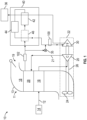
FIG. 1 , illustrated is an embodiment of an environmental control system (ECS) 10 for an aircraft. The ECS 10 is supplied with, for example, bleedairflow 12 from a bleedair supply system 14 of a gas turbine engine. - The environmental control system (ECS) 10 includes a
RAM air circuit 11 including a shell orduct 13 within which one or more heat exchangers are located. Theshell 13 can receive and direct a medium, such asram air flow 18 for example, through aram inlet 19. - The one or
more heat exchangers - The
bleed airflow 12 is input into aprimary heat exchanger 16 of theECS 10 where thebleed airflow 12 exchanges thermal energy with aRAM airflow 18, or alternatively ambient airflow. The bleed airflow is then directed through acompressor 20 of anair cycle machine 22. Thecompressor 20 and fan 24 are driven by, for example,turbine 30 that shares acommon shaft 26 with thecompressor 20 and fan 24. After compression at thecompressor 20, the compressed bleedairflow 21 is directed to asecondary heat exchanger 28 where the compressed bleed airflow is cooled by thermal energy exchange with theRAM airflow 18. Thebleed airflow 12 is then directed towards anexpansion device 30 connected to theshaft 26 for primary expansion. - As shown, the system includes at least one
expansion device 30. Theexpansion device 30 will also be referred to as a turbine or the first turbine herein. - The turbine 30 a mechanical device that includes components for performing thermodynamic work on air that leaves the compressor 20 (e.g., extracts work from or applies work to the compressed air by raising and/or lowering pressure and by raising and/or lowering temperature) and is used to drive the
shaft 26 and thereby drive the fan 24 and thecompressor 20. - As illustrated, before being provided to the
turbine 30, the compressed air is passed through a dehumidification/water removal system 40. This system is described as being part of the ACM for simplicity, but it shall be understood that anysystem 40 connected to a ACM such as ACM 22 shall be considered part of the ACM whether integrated with the ACM or implemented as a separate unit. This is applicable to all embodiments herein. - In the illustrated, non-limiting embodiment the
dehumidification system 40 includes acondenser 42, an optional reheater, and awater collector 44. Thecondenser 42 is a particular type of heat exchanger and thewater collector 44 is a mechanical device that performs a process of removing water from a medium. In an embodiment, thewater collector 44 is a high pressure water separator that removes moisture from a medium at a highest pressure within the environmental control system 10 (e.g., downstream of thecompressor 20 and ram air heat exchanger 28). In an embodiment, thedehumidification system 40 further includes areheater 46. Thereheater 46 is another type of heat exchanger configured to increase the temperature of the air as it passes there through. Thereheater 46 may be arranged generally upstream from thecondenser 42 such that compressed air exitingsecondary heat exchange 28 flows through thereheater 46 and then thecondenser 42 sequentially. - The air is then directed to the
turbine 30 for expansion. After expansion, the air it then again directed through thecondenser 42 and then into thecabin 36 or overboard. The above discussion has described operation in a normal or first mode. - As illustrated, the
ECS 10 can also include a bypass or economy valve (ECV) 35. When theECV 35 is open, the air output from the ram air heat exchanger 38 has a temperature and pressure sufficient to meet the demands of the one or more loads, such as thecabin 36 for example. Herein, whenECV 35 is open, the system is said to be operating in a bypass mode. Accordingly, all or at least a portion of air output from the ramair heat exchanger 28 is configured to bypass including thedehumidification system 40 but not theturbine 30 in order to drive thecompressor 20. - In embodiments herein, a
humidity sensor 100 is provided upstream of theturbine 30. As illustrated, thehumidity sensor 100 is directly upstream of theturbine 30 and downstream of theECV 35. In one embodiment, thishumidity sensor 100 is the only sensor in theECS 10. In such an embodiment, thesensor 100 can be said to be in the "turbine inlet location." Measuring humidity in such a position allows the ECS controls to minimize the risk of rotor icing effects in the turbine 30 (e.g. reduce ACM speed or raise turbine inlet temperature if required). - In prior systems, there was no directly measured humidity. Rather, only temperature and/or pressure was used to approximate it. It should be understood that the humidity sensor 100 (or any other humidity sensor herein, e.g.,
sensor 102 below) can be an integrated circuit (IC) sensor that can measure one or both temperature and pressure as well. This can simplify wiring in the system and may allow for a reduction in the number of separate sensors. More importantly, advanced ECV opening logic based on measured humidity can be utilized, further optimizing system performance. Also, knowing humidity values may help in root cause failure analyses for the ECS components. - Reference is now made to
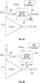
FIGs. 2A and 2B that show two different installations that may be used when measuring humidity. InFIG. 2A , theturbine 30 is shown as having aninlet pipe 200. Thehumidity sensor 100 can divert a small portion the air provided to theturbine 30 via an inlet and an outlet. The inlet is shown as measuringbypass channel 202. Thebypass channel 202 passes through thesensor 100 providing air to the sensor for measurements. - After being measured, the air exits the
sensor 100 via an outlet shown asexhaust 204. The rate of flow through the sensor can be controlled by anexhaust orifice 205 in theexhaust 204. The orifice can be fixed or adjustable. As shown inFIG. 2A , theexhaust 204 can exhaust the air to an ambient environment. This environment can be overboard or the cabin, for example. As shown, thesensor 100 can receive power and can also provide data (measurements) to anECS controller 240. - In
FIG. 2B , theturbine 30 is shown as having aninlet pipe 200. Thehumidity sensor 100 can divert a small portion the air provided to theturbine 30 via ameasuring bypass channel 202. Thebypass channel 202 passes through thesensor 100 providing air to the sensor for measurements. As shown, thesensor 100 can receive power and can also provide data (measurements) to anECS controller 240. - After being measured, the air exits the
sensor 30 viaexhaust 204. The rate of flow through the sensor can be controlled by anexhaust orifice 205 in theexhaust 204. The orifice can be fixed or adjustable. As shown inFIG. 2B , theexhaust 204 can be connected back to theoutlet 207 of theturbine 30. - In the above discussion, only a single sensor has been shown. It shall be understood that one or more optional additional sensors can be provided. For example, in
FIG. 1 , an optionalsecond humidity sensor 102 is shown upstream of thedehumidification system 40. As the skilled artisan will realize, having such a second sensor can provide one more advantages. In particular, having two sensors (in addition to the above advantages of a single sensor) can allow for performance measurements of thedehumidification system 40 and may further provide additional information for a root cause failure analysis. The location ofsensor 102 can also provide the benefit of more accurately determining if moisture is present in the system and therefore utilize the water removal system only when required. - The above, examples are directed to systems that includes one turbine in the ECS. It is also applicable to other configurations. For example, as shown
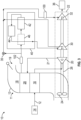
FIG. 3 , theECS 10 can include a pair ofexpansion devices expansion devices system 10, may, but need not be substantially identical. In general, as above, the expansion devices are turbines. Hereinturbine 32 can be referred to as a second turbine. - The first and
second turbines shaft 26 and, as above, are mechanical device that include components for performing thermodynamic work on air that leaves the compressor 20 (e.g., extracts work from or applies work to the compressed air by raising and/or lowering pressure and by raising and/or lowering temperature) and is used to drive theshaft 26 and thereby drive the fan 24 and thecompressor 20. - As illustrated, before being provided to the
first turbine 30, the compressed air is passed through the dehumidification/water removal system 40. In the illustrated, non-limiting embodiment thedehumidification system 40 includes acondenser 42, an optional reheater, and awater collector 44. Thecondenser 42 is a particular type of heat exchanger and thewater collector 44 is a mechanical device that performs a process of removing water from a medium. In an embodiment, thewater collector 44 is a high-pressure water separator that removes moisture from a medium at a highest pressure within the environmental control system 10 (e.g., downstream of thecompressor 20 and ram air heat exchanger 28). In an embodiment, thedehumidification system 40 further includes areheater 46. Thereheater 46 is another type of heat exchanger configured to increase the temperature of the air as it passes there through. Thereheater 46 may be arranged generally upstream from thecondenser 42 such that compressed air exitingsecondary heat exchange 28 flows through thereheater 46 and then thecondenser 42 sequentially. - The air is then directed to the
first turbine 30 via a first inlet tube 200' for expansion. After expansion, the air it then again directed through thecondenser 42 and then into thesecond turbine 32 via asecond inlet tube 200". The expanded air from thesecond turbine 32 can be provided to thecabin 36. - Similar to the above, As illustrated, the
ECS 10 can also include a bypass or economy valve (ECV) 35. When theECV 35 is open, the air output from the ramair heat exchanger 28 has a temperature and pressure sufficient to meet the demands of the one or more loads, such as thecabin 36 for example. Accordingly, all or at least a portion of air output from the ramair heat exchanger 28 is configured to bypass including thedehumidification system 40 and thefirst turbine 30 but not thesecond turbine 32. - In embodiment shown in
FIG. 3 , thehumidity sensor 100 is provided upstream of thesecond turbine 32. As illustrated, thehumidity sensor 100 is directly upstream of thesecond turbine 32 in thesecond inlet tube 200" and downstream of theECV 35. As above, the system ofFIG. 3 can operate in normal and bypass modes based on the position of theECV 35. - In one embodiment, this
humidity sensor 100 is the only sensor in theECS 10. In such an embodiment, thesensor 100 can be said to be in the "second turbine inlet location" on thesecond inlet tube 200". Measuring humidity in such a position allows the ECS controls to minimize the risk of rotor icing effects in the turbine 32 (e.g., reduce ACM speed if required). - It shall be understood that
sensor 100 can be arranged relative to any of turbines herein as shown inFIGs. 2A and 2B . - In the above discussion of
FIG. 3 , only a single sensor has been shown discussed. It shall be understood that one or more optional additional sensors can be provided. For example, inFIG. 3 , an optionalsecond humidity sensor 102 is shown upstream of thedehumidification system 40. As the skilled artisan will realize, having such a second sensor can provide one more advantages. In particular, having two sensors (in addition to the above advantages of a single sensor) can allow for performance measurements of thedehumidification system 40 be used to assess when the dehumidification system is needed and may further provide additional information in support of a root cause failure analysis of a field issue. - While in the above two humidity sensors are shown, additional humidity sensors could also be provided. Further, the location of the sensors could be varied. For example, the
first sensor 100 could be moved such that it is in the first inlet tube 200' of thefirst turbine 30 rather than thesecond inlet tube 200" of thesecond turbine 32. - In all embodiments disclosed herein, if two humidity sensors are provided, the
dehumidification system 40 can be monitored. For example, the difference in humidity upstream of thedehumidification system 40 measured by thesecond humidity sensor 102 can be compared to the humidity measured by thefirst humidity sensor 100. The difference will show the effectiveness ofdehumidification system 40 at removing humidity. Further, the values can be tracked over time to see if the effectiveness ofdehumidification system 40 at removing humidity is decreasing. Such a decrease may lead to determination that thedehumidification system 40 is failing or needs maintenance or both. Such data can also be used to determine a cause of a failure of the air cycle machine. - The term "about" is intended to include the degree of error associated with measurement of the particular quantity based upon the equipment available at the time of filing the application.
- The terminology used herein is for the purpose of describing particular embodiments only and is not intended to be limiting of the present disclosure. As used herein, the singular forms "a", "an" and "the" are intended to include the plural forms as well, unless the context clearly indicates otherwise. It will be further understood that the terms "comprises" and/or "comprising," when used in this specification, specify the presence of stated features, integers, steps, operations, elements, and/or components, but do not preclude the presence or addition of one or more other features, integers, steps, operations, element components, and/or groups thereof.
- While the present disclosure has been described with reference to an exemplary embodiment or embodiments, it will be understood by those skilled in the art that various changes may be made without departing from the scope of the invention as defined by the claims. In addition, many modifications may be made to adapt a particular situation or material to the teachings of the present disclosure without departing from the scope of the invention as defined by the claims.
Claims (13)
- An environmental control system of an aircraft, comprising:a primary heat exchanger (16);a secondary heat exchanger (28); andan air cycle machine (22) including:a compressor (20) fluidly coupled to an outlet of the primary heat exchanger and an inlet of the secondary heat exchanger;a dehumidification system (40) arranged in fluid communication with the outlet of the secondary heat exchanger;a first turbine (30) fluidly coupled to an outlet of the secondary heat exchanger;a second turbine (32) disposed downstream of the first turbine that receives air from the first turbine in a normal mode; anda first humidity sensor (100) disposed fluidly between the first turbine and the second turbine that measures humidity of air that has left the first turbine as it enters the second turbine in the normal mode, or a first humidity sensor (100) disposed fluidly between second heat exchanger and the first turbine that measures humidity of air as it enters the first turbine in the normal mode.
- The system of claim 1, further comprising:
a second humidity sensor (102) disposed fluidly between the secondary heat exchanger and the dehumidification system that measures humidity of air that has left the compressor before it enters the dehumidification system. - The system of claim 1 or 2, wherein the dehumidification system includes a condenser (42) and a water extractor (44), and moisture is removed from air before entering the first turbine in the normal mode.
- The system of claim 3, wherein air exiting the first turbine passes through the condenser before entering the second turbine.
- The system of any preceding claim, wherein the first humidity sensor includes an inlet (200) and an exhaust (204);wherein the second turbine receives the air via a second turbine inlet;wherein the inlet is connected to the second turbine inlet such that air is directed from the second turbine inlet through the first humidity sensor to the exhaust.
- The system of claim 5, wherein the exhaust is connected to an output of the second turbine, or wherein the exhaust is connected to an ambient environment.
- The system of claim 5 or 6, wherein the exhaust includes an exhaust orifice (205) disposed therein that controls a rate of flow through the first humidity sensor.
- The system of any preceding claim, further comprising:a bypass valve (35) that diverts air around the dehumidification system such that air exiting the first turbine can enter the second turbine without passing though the dehumidification system when in a bypass mode;wherein the first humidity sensor is downstream of the bypass valve.
- The system of claim 1, wherein the first humidity sensor includes an inlet and an exhaust;wherein the first turbine receives the air via a first turbine inlet;wherein the inlet is connected to the first turbine inlet such that air is directed from the first turbine inlet through the first humidity sensor to the exhaust.
- The system of claim 9, wherein the exhaust is connected to an output of the first turbine.
- The system of claim 9, wherein the exhaust is connected to an ambient environment.
- The system of claim 9, 10 or 11, wherein the exhaust includes an exhaust orifice disposed therein that controls a rate of flow through the first humidity sensor.
- The system of claim 1, further comprising:a bypass valve (35) that diverts air around the dehumidification system such that air exiting the secondary heat exchanger can enter the first turbine without passing though the dehumidification system when in a bypass mode;wherein the first humidity sensor is downstream of the bypass valve.
Applications Claiming Priority (1)
| Application Number | Priority Date | Filing Date | Title |
|---|---|---|---|
| US17/585,791 US20230234710A1 (en) | 2022-01-27 | 2022-01-27 | Environmental control system including humidity sensor |
Publications (1)
| Publication Number | Publication Date |
|---|---|
| EP4219310A1 true EP4219310A1 (en) | 2023-08-02 |
Family
ID=85132668
Family Applications (1)
| Application Number | Title | Priority Date | Filing Date |
|---|---|---|---|
| EP23153795.2A Pending EP4219310A1 (en) | 2022-01-27 | 2023-01-27 | Environmental control system including humidity sensor |
Country Status (2)
| Country | Link |
|---|---|
| US (1) | US20230234710A1 (en) |
| EP (1) | EP4219310A1 (en) |
Citations (6)
| Publication number | Priority date | Publication date | Assignee | Title |
|---|---|---|---|---|
| US6199387B1 (en) * | 1999-07-30 | 2001-03-13 | Liebherr-Aerospace Lindenberg Gmbh | Air-conditioning system for airplane cabin |
| EP1386837A1 (en) * | 2002-07-31 | 2004-02-04 | Liebherr-Aerospace Lindenberg GmbH | Airconditioning system for aircraft |
| US20150059397A1 (en) * | 2013-09-03 | 2015-03-05 | Hamilton Sundstrand Corporation | Method of operating a multi-pack enviromental control system |
| US9724979B1 (en) * | 2016-04-27 | 2017-08-08 | The Boeing Company | Model-based method to detect abnormal operations in heat exchangers |
| US20170267358A1 (en) * | 2014-09-23 | 2017-09-21 | Commercial Aircraft Corporation Of China, Ltd | Dewatering device for an air conditioning system of a plane |
| US20200180772A1 (en) * | 2018-12-06 | 2020-06-11 | The Boeing Company | Systems and methods to produce aircraft cabin supply air |
-
2022
- 2022-01-27 US US17/585,791 patent/US20230234710A1/en active Pending
-
2023
- 2023-01-27 EP EP23153795.2A patent/EP4219310A1/en active Pending
Patent Citations (6)
| Publication number | Priority date | Publication date | Assignee | Title |
|---|---|---|---|---|
| US6199387B1 (en) * | 1999-07-30 | 2001-03-13 | Liebherr-Aerospace Lindenberg Gmbh | Air-conditioning system for airplane cabin |
| EP1386837A1 (en) * | 2002-07-31 | 2004-02-04 | Liebherr-Aerospace Lindenberg GmbH | Airconditioning system for aircraft |
| US20150059397A1 (en) * | 2013-09-03 | 2015-03-05 | Hamilton Sundstrand Corporation | Method of operating a multi-pack enviromental control system |
| US20170267358A1 (en) * | 2014-09-23 | 2017-09-21 | Commercial Aircraft Corporation Of China, Ltd | Dewatering device for an air conditioning system of a plane |
| US9724979B1 (en) * | 2016-04-27 | 2017-08-08 | The Boeing Company | Model-based method to detect abnormal operations in heat exchangers |
| US20200180772A1 (en) * | 2018-12-06 | 2020-06-11 | The Boeing Company | Systems and methods to produce aircraft cabin supply air |
Non-Patent Citations (1)
| Title |
|---|
| CHOWDHURY SHAFAYAT HASAN ET AL: "A Methodology for the Experimental Validation of an Aircraft ECS Digital Twin Targeting System Level Diagnostics", ANNUAL CONFERENCE OF THE PHM SOCIETY, vol. 11, no. 1, 22 September 2019 (2019-09-22), XP093049521, ISSN: 2325-0178, Retrieved from the Internet <URL:https://papers.phmsociety.org/index.php/phmconf/article/download/888/phmc_19_888> [retrieved on 20230525], DOI: 10.36001/phmconf.2019.v11i1.888 * |
Also Published As
| Publication number | Publication date |
|---|---|
| US20230234710A1 (en) | 2023-07-27 |
Similar Documents
| Publication | Publication Date | Title |
|---|---|---|
| US5086622A (en) | Environmental control system condensing cycle | |
| EP3514065B1 (en) | Aircraft environmental control system | |
| US20190135440A1 (en) | Aircraft enviromental control system with series bleed air turbines | |
| EP3945031B1 (en) | Aircraft environmental control system | |
| US11085673B2 (en) | Advanced environmental control system in an integrated simple cycle pack | |
| CA2928048A1 (en) | Environmental control system utilizing cabin discharge air to power a cycle | |
| CA2416471A1 (en) | Air conditioning system | |
| EP3666656B1 (en) | Alternate fresh air compressor intake for environmental control system | |
| EP3760542A1 (en) | Environmental control system of an aircraft | |
| EP2757343A1 (en) | Sub freezing load heat exchanger bypass | |
| EP3590839A1 (en) | Pressure optimized sourcing of cabin pressurization and component air cooling | |
| EP4219310A1 (en) | Environmental control system including humidity sensor | |
| EP3549866B1 (en) | Liquid reheater heat exchanger in an air cycle system | |
| EP4292937A1 (en) | Ram air turbine powered cabin air compressor | |
| EP4001117A2 (en) | Environmental control system for supersonic commercial aircraft | |
| EP3838762A1 (en) | Air cycle machines, air cycle machine systems, and methods of controlling air flow in air cycle machines | |
| EP3838763A1 (en) | Air cycle machines, air cycle machine systems, and methods of controlling air flow in air cycle machines | |
| EP3789300A1 (en) | A hybrid ecs architecture to reduce engine bleed dependency for aircraft cabin pressure and temperature control | |
| EP4335749A1 (en) | Regeneration using liquid loop of environmental control system | |
| EP4299444A1 (en) | Split regeneration environmental control system | |
| EP4331991A1 (en) | Environmental control system with low inlet pressure | |
| EP3225554B1 (en) | Aircraft air conditioning system including a thermoelectric device | |
| US20240092489A1 (en) | Low pressure air cycle | |
| JP2012255613A (en) | Air conditioner | |
| EP4147765A1 (en) | Integrated mid-pressure water separator |
Legal Events
| Date | Code | Title | Description |
|---|---|---|---|
| PUAI | Public reference made under article 153(3) epc to a published international application that has entered the european phase |
Free format text: ORIGINAL CODE: 0009012 |
|
| STAA | Information on the status of an ep patent application or granted ep patent |
Free format text: STATUS: THE APPLICATION HAS BEEN PUBLISHED |
|
| AK | Designated contracting states |
Kind code of ref document: A1 Designated state(s): AL AT BE BG CH CY CZ DE DK EE ES FI FR GB GR HR HU IE IS IT LI LT LU LV MC ME MK MT NL NO PL PT RO RS SE SI SK SM TR |
|
| STAA | Information on the status of an ep patent application or granted ep patent |
Free format text: STATUS: REQUEST FOR EXAMINATION WAS MADE |
|
| 17P | Request for examination filed |
Effective date: 20240202 |
|
| RBV | Designated contracting states (corrected) |
Designated state(s): AL AT BE BG CH CY CZ DE DK EE ES FI FR GB GR HR HU IE IS IT LI LT LU LV MC ME MK MT NL NO PL PT RO RS SE SI SK SM TR |