EP4218547A1 - Device for detecting caries - Google Patents
Device for detecting caries Download PDFInfo
- Publication number
- EP4218547A1 EP4218547A1 EP22153623.8A EP22153623A EP4218547A1 EP 4218547 A1 EP4218547 A1 EP 4218547A1 EP 22153623 A EP22153623 A EP 22153623A EP 4218547 A1 EP4218547 A1 EP 4218547A1
- Authority
- EP
- European Patent Office
- Prior art keywords
- detection device
- caries detection
- fluorescent particles
- caries
- quantum dots
- Prior art date
- Legal status (The legal status is an assumption and is not a legal conclusion. Google has not performed a legal analysis and makes no representation as to the accuracy of the status listed.)
- Pending
Links
Images


Classifications
-
- A—HUMAN NECESSITIES
- A61—MEDICAL OR VETERINARY SCIENCE; HYGIENE
- A61B—DIAGNOSIS; SURGERY; IDENTIFICATION
- A61B5/00—Measuring for diagnostic purposes; Identification of persons
- A61B5/0059—Measuring for diagnostic purposes; Identification of persons using light, e.g. diagnosis by transillumination, diascopy, fluorescence
- A61B5/0071—Measuring for diagnostic purposes; Identification of persons using light, e.g. diagnosis by transillumination, diascopy, fluorescence by measuring fluorescence emission
-
- A—HUMAN NECESSITIES
- A61—MEDICAL OR VETERINARY SCIENCE; HYGIENE
- A61B—DIAGNOSIS; SURGERY; IDENTIFICATION
- A61B5/00—Measuring for diagnostic purposes; Identification of persons
- A61B5/0059—Measuring for diagnostic purposes; Identification of persons using light, e.g. diagnosis by transillumination, diascopy, fluorescence
- A61B5/0082—Measuring for diagnostic purposes; Identification of persons using light, e.g. diagnosis by transillumination, diascopy, fluorescence adapted for particular medical purposes
- A61B5/0088—Measuring for diagnostic purposes; Identification of persons using light, e.g. diagnosis by transillumination, diascopy, fluorescence adapted for particular medical purposes for oral or dental tissue
-
- A—HUMAN NECESSITIES
- A61—MEDICAL OR VETERINARY SCIENCE; HYGIENE
- A61B—DIAGNOSIS; SURGERY; IDENTIFICATION
- A61B5/00—Measuring for diagnostic purposes; Identification of persons
- A61B5/103—Detecting, measuring or recording devices for testing the shape, pattern, colour, size or movement of the body or parts thereof, for diagnostic purposes
- A61B5/1032—Determining colour for diagnostic purposes
-
- A—HUMAN NECESSITIES
- A61—MEDICAL OR VETERINARY SCIENCE; HYGIENE
- A61B—DIAGNOSIS; SURGERY; IDENTIFICATION
- A61B5/00—Measuring for diagnostic purposes; Identification of persons
- A61B5/68—Arrangements of detecting, measuring or recording means, e.g. sensors, in relation to patient
- A61B5/6801—Arrangements of detecting, measuring or recording means, e.g. sensors, in relation to patient specially adapted to be attached to or worn on the body surface
- A61B5/6813—Specially adapted to be attached to a specific body part
- A61B5/6814—Head
- A61B5/682—Mouth, e.g., oral cavity; tongue; Lips; Teeth
Definitions
- the present invention relates to a caries detection device, a caries detection system with a caries detection device and several methods for producing a caries detection device.
- Carious areas of teeth in a dentition can be detected in different ways, such as by X-ray examination, with a mechanical probe, by transillumination or by pain in the patient.
- a caries detection device having fluorescent particles that lose the fluorescence property on contact with a sulfur compound. Particles that change their fluorescence properties as soon as they come into contact with are used to detect carious areas of a set of teeth Sulfur compounds that are released from the carious sites. Fluorescence is the spontaneous emission of light shortly after a material has been excited by light. The emitted photons are usually lower in energy than those previously absorbed. If the particles have come into contact with the sulfur compounds, they lose their previously existing fluorescence properties. When they are later irradiated with light, these particles then appear darker than if they had not come into contact with the sulfur compounds.
- the caries detection device achieves the technical advantage, for example, that carious areas can be detected without having to use X-rays for this purpose and without exposure to radiation.
- carious areas can also be localized that are not visible from the outside, for example if they are under a crown, since the sulfur compounds also reach the caries detection device.
- the caries detection device is easy to handle, so that it can also be used by a user in the private sphere.
- the sulfur compound comprises hydrogen sulfide or organic sulfur compounds.
- the organic sulfur compounds include, for example, sulfur-containing proteins, methanethiol, methyl mercaptan or dimethyl sulfide. This achieves the technical advantage, for example, that carious areas within the dentition can be reliably identified.
- the fluorescent particles comprise zinc sulfide or cadmium telluride. This achieves the technical advantage, for example, that a strong fluorescence effect is achieved with simultaneous high sensitivity and carious areas can be easily identified. A contrast of fluorescent and non-fluorescent areas is high and requires little sulfur gas for destroying the fluorescent property.
- the fluorescent particles are formed by quantum dots.
- a quantum dot is a nanoscopic material structure.
- the charge carriers, such as electrons or holes, in a quantum dot are restricted in their mobility in all three spatial directions to such an extent that their energy can no longer assume continuous but only discrete values. This achieves the technical advantage, for example, that the fluorescence properties can be adjusted in a targeted manner.
- the quantum dots have a predetermined shape and/or predetermined dimensions.
- the shape, size or number of electrons in quantum dots can vary. This achieves the technical advantage, for example, that the electronic and optical properties of the quantum dots can be controlled in a targeted manner.
- the atomic order is about 10 4 atoms.
- the fluorescent particles or quantum dots are arranged in a predetermined three-dimensional structure.
- the fluorescent particles or quantum dots may be arranged at regular intervals in the caries detection device or in a cubic or hexagonal three-dimensional structure. This achieves the technical advantage, for example, that a more precise detection of the fluorescence or the fluorescence quenching is made possible.
- the fluorescent particles or quantum dots are arranged homogeneously or in a predetermined density.
- the density of the fluorescent particles or quantum dots is, for example, 0.01-1.0% by mass, preferably 0.01-0.1% by mass. This achieves the technical advantage, for example, that more accurate measured values in relation to the extent of a carious lesion can be obtained on the basis of the density reference.
- the fluorescent particles are arranged in a first spatial region of the caries detection device in a first density and in a second spatial region of the caries detection device in a second density. This achieves the technical advantage, for example, that the sensitivity for detecting caries is increased in certain areas of the caries detection device.
- the caries detection device is a toothbrush, a dental splint, a bite splint, an aligner splint, a plastic film, dental floss, chewing gum, a partial denture, a varnish, a cement, or a bracket or an electronic device .
- the technical problem is solved by a caries detection system with a caries detection device according to the first aspect and a light source for emitting radiation with a wavelength that is smaller than 500 nm.
- the light source is, for example, a light-emitting diode or a laser diode. This achieves the technical advantage, for example, that carious areas can be optically detected directly.
- the caries detection system comprises a light sensor for detecting fluorescent light.
- the light sensor can be formed by an electronic camera, for example. This achieves the technical advantage, for example, that the intensity or an image of the decrease in fluorescence can be recorded.
- the technical problem is solved by a method for manufacturing a caries detection device, comprising the steps of manufacturing the caries detection device in a molding process; and an introduction of fluorescent particles into the caries detection device, which lose the fluorescence property on contact with a sulfur compound.
- the caries detection device is produced in a three-dimensional printing process and the fluorescent particles are introduced into the caries detection device by the printing process.
- a homogeneous mixture of the material of construction and the particles can be used in the printing process.
- the density of fluorescent particles is homogeneous.
- the particles can also be arranged during the three-dimensional printing process through a separate channel, such as a nozzle, at specific points on the caries detection device by means of the printing process. This achieves the technical advantage, for example, that the caries detection device can be produced quickly and efficiently in a predetermined shape.
- the caries detection device is produced by deep-drawing a film and the fluorescent particles are introduced into the caries detection device through the film.
- the fluorescent particles are incorporated into the film before it is thermoformed. This achieves the technical advantage, for example, that the caries detection device can be manufactured in a simple manner.
- the caries detection device is Milling is made from a blank and the fluorescent particles are introduced through the blank into the caries detection device.
- the fluorescent particles are incorporated into the blank before it is milled. This achieves the technical advantage, for example, that a blank can be used to produce a specific density of fluorescent particles.
- the fluorescent particles are introduced by applying a lacquer. This achieves the technical advantage, for example, that the lacquer can be applied to the caries detection device subsequently for caries detection.
- this comprises the step of emitting radiation through a light source with a wavelength that is less than 500 nm.
- the task of the caries detection device is to detect carious active lesions of a tooth.
- sulfur compounds are used, which are caused by the carious active lesions.
- the bite splint includes, for example, fluorescent particles 101 made of zinc sulfide (ZnS) or cadmium telluride (CdTe).
- the fluorescent particles can be quantum dots.
- Fluorescent particles 101 for example quantum dots (QD—quantum nanodots) based on zinc sulfide, can be incorporated into the bite splint 100.
- the bite splint 100 is formed of transparent material placed close to the carious site 107 of a tooth 109 for several hours.
- the sulfur compounds caused are, for example, sulphur-containing proteins, methanethiol, methyl mercaptan or dimethyl sulphide.
- the bite splint 100 can also be printed with a 3D printer or from a curing two-component material getting produced. When exposed to a light that causes the fluorescent particles 101 to glow, the entire bite splint 100 initially glows homogeneously. When the bite splint 100 is worn for a period of time so that the particles 101 come into contact with the sulfur compounds, the fluorescent particles 101 are caused to decrease in fluorescence. As a result, the luminosity of the fluorescence decreases or is completely lost at these points of the bite splint 100 . Therefore, when the bite splint 100 is subsequently illuminated, the carious areas 107 on the teeth 109 can be located. In addition to the fluorescent particles 101 , the bite splint 100 can also include fluoride in order to fluoridate teeth while the bite splint 100 is being worn.
- the bite splint can be produced with little effort. There is no radiation exposure when localizing carious areas 107.
- the bite splint can be used at home or only for routine examinations. In addition, the microbiological load (active lesion) is detected.
- the caries detection device can be not only a bite splint, but also a toothbrush (bristles), a dental splint, an aligner splint, a plastic film, dental floss, chewing gum, a partial denture, a varnish, a cement, or a bracket or an electronic Dental device be formed. All of these objects can include the fluorescent particles 101 in order to identify carious structures. When the fluorescent particles 101 are integrated into a structured film, this can be used as a caries detection film.
- the fluorescent particles 101 can be provided at different points of the caries detection device in a different concentration or density in order to enable a semi-quantitative evaluation.
- the fluorescent particles 101 can be formed by quantum dots 103, which generate different spectra (excitation and emission) and react to different gases. It is also possible for quantum dots 103 to be designed in such a way that they only react to the respective sulfur compound after a specific time. As a result, a change in the structure of the tooth 109 over time can be recorded.
- the quantum dots 103 are fluorescent nanoparticles of certain semiconductor crystals whose electronic properties are highly dependent on the particle size, such as Zn-Cu-In-S or ZnS. The smaller the quantum dots 103, the more the fluorescence color is shifted toward blue. Quantum dots 103 make it possible to produce full color spectrum emission from the same material with different diameters.
- Quantum dots 103 Since the size of the quantum dots 103 can be precisely adjusted during their manufacture, their electronic and fluorescence properties can be precisely controlled.
- Quantum dots 103 have a high stability due to their construction from inorganic material.
- CdTe quantum dots 103 can be functionalized with carboxyl groups (-COOH) so that they are water soluble and allow for covalent attachment to proteins and other molecules.
- the quantum dots 103 have, for example, a spherical, pyramidal, cuboid, Cylindrical or tetrahedral geometry.
- the quantum dots 103 have a dimension of 1 to 50 nm.
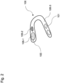
- FIG. 2 shows a further schematic view of a bite splint 100 as a caries detection device.
- the fluorescent particles 101 are arranged in a first density
- the fluorescent particles 101 are arranged in a second density.
- the first density and the second density are different from each other.
- the quantum dots of the fluorescent particles 101 in the first region 105 - 1 of the bite splint 100 can also have a different size or shape than the quantum dots of the fluorescent particles 101 in the second region 105 - 1 of the bite splint 100 .
- FIG. 12 shows a schematic view of a dental electronic device 200 as a caries detection device.
- the electronic dental device 200 such as a portable pen (pen), sucks the volatile sulfur compounds on the tooth 109 through a flexible channel 201.
- the fluorescent particles 101 are arranged in the interior of the electronic dental device 200, via which the sucked-off sulfur compounds are conducted.
- the electronic device 200 includes an illumination device 203, which excites the fluorescent particles 101 to fluoresce.
- the electronic dental device 200 includes a light sensor 205 for detecting an intensity of the fluorescent light, such as a light emitting diode. If the intensity of the fluorescent light decreases, there is a carious change at the point from which the sulfur compounds were sucked out. In this way, fluorescent particles 101 can be used in analysis in order to obtain precise information about carious changes in teeth.
- the caries detection system 200 comprises the caries detection device and an additional light source 301 for emitting radiation with a wavelength that is less than 500 nm.
- the light source 301 can be activated to excite the fluorescence of the caries detection device.
- the light source 301 is formed by a light-emitting diode, for example. The light from the light source 301 impinges on the caries detection device.
- the caries detection system 300 includes a light sensor 303 for detecting fluorescent light emitted from the caries detection device having the fluorescent particles 101 .
- the light sensor 303 can be formed by an electronic camera with which the fluorescent light of the caries detection device can be recorded.
- the electronic camera creates a record that can be stored in an electronic file.
- detection and analysis of the fluorescence radiation can also be carried out with a mobile phone equipped with an electronic camera and a filter
- the caries detection device can be manufactured using different methods. In a first method, the caries detection device can be produced using a three-dimensional printing method. In the three-dimensional printing manufacturing process, the manufacturing material is applied layer by layer so that three-dimensional objects can be created.
- the fluorescent particles 101 are introduced, which lose the fluorescence property when they come into contact with the sulfur compound.
- this can be done by using a production material in which the fluorescent particles 101 have been admixed prior to processing by the printing process.
- the fluorescent particles 101 can be a separate part of the printing process and can be supplied separately from the production material in the layered structure. This makes it possible to arrange the fluorescent particles 101 at specific positions of the caries detection device.
- the caries detection device can be manufactured by deep-drawing a sheet with fluorescent particles 101 which lose the fluorescent property when they come into contact with a sulfur compound.
- the film is formed into a hollow body that is open on one side by being pulled onto or into a shaped body.
- the fluorescent particles 101 are distributed homogeneously in the film. However, it is also possible to use a film in which the fluorescent particles 101 are arranged in one or more layers.
- the fluorescent particles 101 in of the foil can be arranged at certain predetermined intervals, for example in a hexagonal or cubic structure.
- a foil can also be used which comprises a different density of the fluorescent particles 101 at different locations. In this way, specific areas of the caries detection device can be produced with a higher or lower density of fluorescent particles 101 . In this way, certain areas can react more sensitively to carious changes. For example, a structured bite splint can be created in this way in order to increase sensitivity.
- the caries detection device can be manufactured by milling out a block, such as a blank, with fluorescent particles 101 which lose the fluorescent property when in contact with a sulfur compound.
- the fluorescent particles 101 can also be distributed homogeneously in the block.
- the fluorescent particles 101 can also be arranged in one or more layers or spatial regions of the block. A block comprising a different density of the fluorescent particles 101 at different locations can also be used.
- Radiation or light with a wavelength of less than 500 nm, preferably less than 400 nm, can then be emitted within the process. This radiation impinges on the caries detection device and excites the fluorescent particles 101 of the caries detection device to fluoresce. If these have previously come into contact with a carious site, there will be less fluorescence than if this was not the case.
- All method steps can be implemented by devices that are suitable for carrying out the respective method step. All functions performed by physical features can be a method step of a method.
Landscapes
- Health & Medical Sciences (AREA)
- Life Sciences & Earth Sciences (AREA)
- Surgery (AREA)
- Biophysics (AREA)
- Pathology (AREA)
- Engineering & Computer Science (AREA)
- Biomedical Technology (AREA)
- Heart & Thoracic Surgery (AREA)
- Medical Informatics (AREA)
- Molecular Biology (AREA)
- Physics & Mathematics (AREA)
- Animal Behavior & Ethology (AREA)
- General Health & Medical Sciences (AREA)
- Public Health (AREA)
- Veterinary Medicine (AREA)
- Audiology, Speech & Language Pathology (AREA)
- Dentistry (AREA)
- Oral & Maxillofacial Surgery (AREA)
- Luminescent Compositions (AREA)
- Investigating, Analyzing Materials By Fluorescence Or Luminescence (AREA)
Abstract
Die vorliegende Erfindung betrifft eine Karieserfassungsvorrichtung (100), mit fluoreszierenden Partikeln (101), die bei Kontakt mit einer Schwefelverbindung die Fluoreszenzeigenschaft verlieren.The present invention relates to a caries detection device (100) with fluorescent particles (101) which lose their fluorescence property when they come into contact with a sulfur compound.
Description
Die vorliegende Erfindung betrifft eine Karieserfassungsvorrichtung, ein Karieserfassungssystem mit einer Karieserfassungsvorrichtung und mehrere Verfahren zum Herstellen einer Karieserfassungsvorrichtung.The present invention relates to a caries detection device, a caries detection system with a caries detection device and several methods for producing a caries detection device.
Kariöse Stellen von Zähnen in einem Gebiss können auf unterschiedliche Weise erkannt werden, wie beispielsweise durch Röntgenuntersuchung, mit einer mechanischen Sonde, durch Transillumination oder durch Schmerzen beim Patienten.Carious areas of teeth in a dentition can be detected in different ways, such as by X-ray examination, with a mechanical probe, by transillumination or by pain in the patient.
Es ist die technische Aufgabe der vorliegenden Erfindung, eine Karieserfassungsvorrichtung bereitzustellen, mit der kariöse Stellen in einem Gebiss auf einfache Weise erfasst werden können, ohne dass hierbei zu einer Strahlenbelastung kommt.It is the technical object of the present invention to provide a caries detection device with which carious areas in a set of teeth can be detected in a simple manner without exposure to radiation occurring in the process.
Diese technische Aufgabe wird durch Gegenstände nach den unabhängigen Ansprüchen gelöst. Technisch vorteilhafte Ausführungsformen sind Gegenstand der abhängigen Ansprüche, der Beschreibung und der Zeichnungen.This technical problem is solved by subject matter according to the independent claims. Technically advantageous embodiments are the subject matter of the dependent claims, the description and the drawings.
Gemäß einem ersten Aspekt wird die technische Aufgabe durch eine Karieserfassungsvorrichtung gelöst, mit fluoreszierenden Partikeln, die bei Kontakt mit einer Schwefelverbindung die Fluoreszenzeigenschaft verlieren. Zur Erfassung von kariösen Stellen eines Gebisses werden Partikel verwendet, die ihre Fluoreszenzeigenschaft verändern, sobald diese in Kontakt mit Schwefelverbindungen geraten, die von den kariösen Stellen freigesetzt werden. Fluoreszenz ist die spontane Emission von Licht kurz nach der Anregung eines Materials durch Licht. Dabei sind die emittierten Photonen in der Regel energieärmer als die vorher absorbierten. Sind die Partikel in Kontakt mit den Schwefelverbindungen gekommen, verlieren diese ihre zuvor vorhandene Fluoreszenzeigenschaft. Bei späterer Bestrahlung mit Licht erscheinen diese Partikel dann dunkler, als wenn diese nicht mit den Schwefelverbindungen in Kontakt gekommen wären.According to a first aspect, the technical problem is solved by a caries detection device having fluorescent particles that lose the fluorescence property on contact with a sulfur compound. Particles that change their fluorescence properties as soon as they come into contact with are used to detect carious areas of a set of teeth Sulfur compounds that are released from the carious sites. Fluorescence is the spontaneous emission of light shortly after a material has been excited by light. The emitted photons are usually lower in energy than those previously absorbed. If the particles have come into contact with the sulfur compounds, they lose their previously existing fluorescence properties. When they are later irradiated with light, these particles then appear darker than if they had not come into contact with the sulfur compounds.
Dunkle (nicht-fluoreszierende) Stellen der Karieserfassungsvorrichtung zeigen daher eine vorhandene kariöse Läsion an, von der Schwefelverbindungen ausgehen.Dark (non-fluorescent) spots on the caries detection device therefore indicate the presence of a carious lesion that emanates sulfur compounds.
Durch die Karieserfassungsvorrichtung wird beispielsweise der technische Vorteil erreicht, dass kariöse Stellen erkannt werden können, ohne dass hierzu Röntgenstrahlung verwendet werden muss und keine Strahlenbelastung auftritt. Zudem können auch kariöse Stellen lokalisiert werden, die von außen nicht sichtbar sind, beispielsweise wenn diese unter einer Krone liegen, da die Schwefelverbindungen ebenfalls die Karieserfassungsvorrichtung erreichen. Die Handhabung der Karieserfassungsvorrichtung ist einfach, so dass diese von einem Benutzer auch im privaten Bereich verwendet werden kann.The caries detection device achieves the technical advantage, for example, that carious areas can be detected without having to use X-rays for this purpose and without exposure to radiation. In addition, carious areas can also be localized that are not visible from the outside, for example if they are under a crown, since the sulfur compounds also reach the caries detection device. The caries detection device is easy to handle, so that it can also be used by a user in the private sphere.
In einer technisch vorteilhaften Ausführungsform der Karieserfassungsvorrichtung umfasst die Schwefelverbindung Schwefelwasserstoff oder organische Schwefelverbindungen. Die organischen Schwefelverbindungen umfassen beispielsweise schwefelhaltige Proteine, Methanthiol, Methylmercaptan oder Dimethylsulfid. Dadurch wird beispielsweise der technische Vorteil erreicht, dass kariöse Stellen innerhalb des Gebisses zuverlässig erkannt werden können.In a technically advantageous embodiment of the caries detection device, the sulfur compound comprises hydrogen sulfide or organic sulfur compounds. The organic sulfur compounds include, for example, sulfur-containing proteins, methanethiol, methyl mercaptan or dimethyl sulfide. This achieves the technical advantage, for example, that carious areas within the dentition can be reliably identified.
In einer weiteren technisch vorteilhaften Ausführungsform der Karieserfassungsvorrichtung umfassen die fluoreszierenden Partikel Zinksulfid oder Cadmiumtellurid. Dadurch wird beispielsweise der technische Vorteil erreicht, dass ein starker Fluoreszenzeffekt bei gleichzeitiger hoher Sensitivität erreicht wird und kariöse Stellen gut erkannt werden können. Ein Kontrast von fluoreszierenden und nicht fluoreszierenden Bereichen ist hoch und erfordert wenig Schwefelgase für die Zerstörung der Fluoreszenzeigenschaft.In a further technically advantageous embodiment of the caries detection device, the fluorescent particles comprise zinc sulfide or cadmium telluride. This achieves the technical advantage, for example, that a strong fluorescence effect is achieved with simultaneous high sensitivity and carious areas can be easily identified. A contrast of fluorescent and non-fluorescent areas is high and requires little sulfur gas for destroying the fluorescent property.
In einer weiteren technisch vorteilhaften Ausführungsform der Karieserfassungsvorrichtung sind die fluoreszierenden Partikel durch Quantenpunkte gebildet. Ein Quantenpunkt ist eine nanoskopische Materialstruktur. Die Ladungsträger, wie beispielsweise Elektronen oder Löcher, in einem Quantenpunkt sind in ihrer Beweglichkeit in allen drei Raumrichtungen so weit eingeschränkt, dass ihre Energie nicht mehr kontinuierliche, sondern nur noch diskrete Werte annehmen kann. Dadurch wird beispielsweise der technische Vorteil erreicht, dass sich die Fluoreszenzeigenschaften gezielt einstellen lassen.In a further technically advantageous embodiment of the caries detection device, the fluorescent particles are formed by quantum dots. A quantum dot is a nanoscopic material structure. The charge carriers, such as electrons or holes, in a quantum dot are restricted in their mobility in all three spatial directions to such an extent that their energy can no longer assume continuous but only discrete values. This achieves the technical advantage, for example, that the fluorescence properties can be adjusted in a targeted manner.
In einer weiteren technisch vorteilhaften Ausführungsform der Karieserfassungsvorrichtung weisen die Quantenpunkte eine vorgegebene Form und/oder vorgegebene Abmessung auf. Die Form, Größe oder die Anzahl von Elektronen in Quantenpunkten kann unterschiedlich vorgegeben sein. Dadurch wird beispielsweise der technische Vorteil erreicht, dass sich die elektronischen und optische Eigenschaften der Quantenpunkten gezielt steuern lassen. Typischerweise beträgt die atomare Größenordnung ca. 104 Atome.In a further technically advantageous embodiment of the caries detection device, the quantum dots have a predetermined shape and/or predetermined dimensions. The shape, size or number of electrons in quantum dots can vary. This achieves the technical advantage, for example, that the electronic and optical properties of the quantum dots can be controlled in a targeted manner. Typically, the atomic order is about 10 4 atoms.
In einer weiteren technisch vorteilhaften Ausführungsform der Karieserfassungsvorrichtung sind die fluoreszierenden Partikel oder Quantenpunkte in einer vorgegebenen dreidimensionalen Struktur angeordnet. Beispielsweise können die fluoreszierenden Partikel oder Quantenpunkte mit gleichmäßigen Abständen in der Karieserfassungsvorrichtung oder in einer kubischen oder hexagonalen dreidimensionalen Struktur angeordnet sein. Dadurch wird beispielsweise der technische Vorteil erreicht, dass eine genauere Erfassung der Fluoreszenz oder des Fluoreszenz-Quenchings ermöglicht wird.In a further technically advantageous embodiment of the caries detection device, the fluorescent particles or quantum dots are arranged in a predetermined three-dimensional structure. For example, the fluorescent particles or quantum dots may be arranged at regular intervals in the caries detection device or in a cubic or hexagonal three-dimensional structure. This achieves the technical advantage, for example, that a more precise detection of the fluorescence or the fluorescence quenching is made possible.
In einer weiteren technisch vorteilhaften Ausführungsform der Karieserfassungsvorrichtung sind die fluoreszierenden Partikel oder Quantenpunkte homogen oder in einer vorgegebenen Dichte angeordnet. Die Dichte der fluoreszierenden Partikel oder Quantenpunkte beträgt beispielsweise 0.01 - 1.0 Massenprozent, vorzugsweise 0.01 - 0.1 Massenprozent. Dadurch wird beispielsweise der technische Vorteil erreicht, dass sich aufgrund der Dichtereferenz genauere Messwerte in Bezug zu dem Ausmaß einer kariösen Läsion gewinnen lassen.In a further technically advantageous embodiment of the caries detection device, the fluorescent particles or quantum dots are arranged homogeneously or in a predetermined density. The density of the fluorescent particles or quantum dots is, for example, 0.01-1.0% by mass, preferably 0.01-0.1% by mass. This achieves the technical advantage, for example, that more accurate measured values in relation to the extent of a carious lesion can be obtained on the basis of the density reference.
In einer weiteren technisch vorteilhaften Ausführungsform der Karieserfassungsvorrichtung sind die fluoreszierenden Partikel in einem ersten räumlichen Bereich der Karieserfassungsvorrichtung in einer ersten Dichte angeordnet und einem zweiten räumlichen Bereich der Karieserfassungsvorrichtung in einer zweiten Dichte angeordnet. Dadurch wird beispielsweise der technische Vorteil erreicht, dass in bestimmten Bereichen der Karieserfassungsvorrichtung die Sensitivität zur Karieserfassung erhöht wird.In a further technically advantageous embodiment of the caries detection device, the fluorescent particles are arranged in a first spatial region of the caries detection device in a first density and in a second spatial region of the caries detection device in a second density. This achieves the technical advantage, for example, that the sensitivity for detecting caries is increased in certain areas of the caries detection device.
In einer weiteren technisch vorteilhaften Ausführungsform der Karieserfassungsvorrichtung ist die Karieserfassungsvorrichtung eine Zahnbürste, eine Zahnschiene, eine Aufbissschiene, eine Aligner-Schiene, eine Kunststofffolie, eine Zahnseide, ein Kaugummi, eine Teilprothese, ein Lack, ein Zement, oder ein Bracket oder ein elektronisches Gerät. Dadurch wird beispielsweise der technische Vorteil erreicht, dass die Karieserfassung von Gegenständen durchgeführt werden kann, die bereits zu einem anderen Zweck im Dentalbereich eingesetzt werden.In another technically advantageous embodiment of the caries detection device, the caries detection device is a toothbrush, a dental splint, a bite splint, an aligner splint, a plastic film, dental floss, chewing gum, a partial denture, a varnish, a cement, or a bracket or an electronic device . This achieves the technical advantage, for example, that the caries detection can be carried out on objects that are already being used for another purpose in the dental field.
Gemäß einem zweiten Aspekt wird die technische Aufgabe durch ein Karieserfassungssystem mit einer Karieserfassungsvorrichtung nach dem ersten Aspekt und einer Lichtquelle zum Emittieren von Strahlung mit einer Wellenlänge gelöst, die kleiner als 500 nm ist. Die Lichtquelle ist beispielsweise eine Leuchtdiode oder eine Laserdiode. Dadurch wird beispielsweise der technische Vorteil erreicht, dass kariöse Stellen direkt optisch erfasst werden können.According to a second aspect, the technical problem is solved by a caries detection system with a caries detection device according to the first aspect and a light source for emitting radiation with a wavelength that is smaller than 500 nm. The light source is, for example, a light-emitting diode or a laser diode. This achieves the technical advantage, for example, that carious areas can be optically detected directly.
In einer technisch vorteilhaften Ausführungsform des Karieserfassungssystems umfasst das Karieserfassungssystem einen Lichtsensor zum Erfassen von Fluoreszenzlicht. Der Lichtsensor kann beispielsweise durch eine elektronische Kamera gebildet sein. Dadurch wird beispielsweise der technische Vorteil erreicht, dass die Intensität oder ein Bild des Fluoreszenzabnahme erfasst werden kann.In a technically advantageous embodiment of the caries detection system, the caries detection system comprises a light sensor for detecting fluorescent light. The light sensor can be formed by an electronic camera, for example. This achieves the technical advantage, for example, that the intensity or an image of the decrease in fluorescence can be recorded.
Gemäß einem dritten Aspekt wird die technische Aufgabe durch ein Verfahren zum Herstellen einer Karieserfassungsvorrichtung gelöst, mit den Schritten eines Herstellens der Karieserfassungsvorrichtung in einem Formgebungsverfahren; und eines Einbringens von fluoreszierenden Partikeln in die Karieserfassungsvorrichtung, die bei Kontakt mit einer Schwefelverbindung die Fluoreszenzeigenschaft verlieren. Dadurch werden die gleichen technischen Vorteile wie durch die Karieserfassungsvorrichtung nach dem ersten Aspekt erreicht.According to a third aspect, the technical problem is solved by a method for manufacturing a caries detection device, comprising the steps of manufacturing the caries detection device in a molding process; and an introduction of fluorescent particles into the caries detection device, which lose the fluorescence property on contact with a sulfur compound. This achieves the same technical advantages as the caries detection device according to the first aspect.
In einer technisch vorteilhaften Ausführungsform des Verfahrens wird die Karieserfassungsvorrichtung in einem dreidimensionalen Druckverfahren hergestellt und die fluoreszierenden Partikel werden durch das Druckverfahren in die Karieserfassungsvorrichtung eingebracht. In dem Druckverfahren kann eine homogene Mischung aus dem Herstellungsmaterial und den Partikeln verwendet werden. Die Dichte an fluoreszierenden Partikeln ist homogen. Die Partikel können aber auch während dem dreidimensionalen Druckverfahren durch einen eigenen Kanal, wie beispielsweise eine Düse, an bestimmten Stellen der Karieserfassungsvorrichtung mittels des Druckverfahrens angeordnet werden. Dadurch wird beispielsweise der technische Vorteil erreicht, dass die Karieserfassungsvorrichtung schnell und effizient in einer vorgegebenen Form hergestellt werden kann.In a technically advantageous embodiment of the method, the caries detection device is produced in a three-dimensional printing process and the fluorescent particles are introduced into the caries detection device by the printing process. A homogeneous mixture of the material of construction and the particles can be used in the printing process. The density of fluorescent particles is homogeneous. However, the particles can also be arranged during the three-dimensional printing process through a separate channel, such as a nozzle, at specific points on the caries detection device by means of the printing process. This achieves the technical advantage, for example, that the caries detection device can be produced quickly and efficiently in a predetermined shape.
In einer weiteren technisch vorteilhaften Ausführungsform des Verfahrens wird die Karieserfassungsvorrichtung durch Tiefziehen einer Folie hergestellt und die fluoreszierenden Partikel werden durch die Folie in die Karieserfassungsvorrichtung eingebracht. Die fluoreszierenden Partikel sind in der Folie eingearbeitet, bevor diese tiefgezogen wird. Dadurch wird beispielsweise der technische Vorteil erreicht, dass die Karieserfassungsvorrichtung auf einfache Weise hergestellt werden kann.In a further technically advantageous embodiment of the method, the caries detection device is produced by deep-drawing a film and the fluorescent particles are introduced into the caries detection device through the film. The fluorescent particles are incorporated into the film before it is thermoformed. This achieves the technical advantage, for example, that the caries detection device can be manufactured in a simple manner.
In einer weiteren technisch vorteilhaften Ausführungsform des Verfahrens wird die Karieserfassungsvorrichtung durch Herausfräsen aus einem Rohling hergestellt und die fluoreszierenden Partikel werden durch den Rohling in die Karieserfassungsvorrichtung eingebracht. Die fluoreszierenden Partikel sind in dem Rohling eingearbeitet, bevor dieser gefräst wird. Dadurch wird beispielsweise der technische Vorteil erreicht, dass aus einem Rohling mit einer bestimmten Dichte an fluoreszierenden Partikeln hergestellt werden kann.In a further technically advantageous embodiment of the method, the caries detection device is Milling is made from a blank and the fluorescent particles are introduced through the blank into the caries detection device. The fluorescent particles are incorporated into the blank before it is milled. This achieves the technical advantage, for example, that a blank can be used to produce a specific density of fluorescent particles.
In einer weiteren technisch vorteilhaften Ausführungsform des Verfahrens werden die fluoreszierenden Partikel durch Aufbringen eines Lackes eingebracht. Dadurch wird beispielsweise der technische Vorteil erreicht, dass der Lack nachträglich zur Karieserfassung auf die Karieserfassungsvorrichtung aufgebracht werden kann.In a further technically advantageous embodiment of the method, the fluorescent particles are introduced by applying a lacquer. This achieves the technical advantage, for example, that the lacquer can be applied to the caries detection device subsequently for caries detection.
In einer weiteren technisch vorteilhaften Ausführungsform des Verfahrens umfasst dieses den Schritt eines Emittierens von Strahlung durch eine Lichtquelle mit einer Wellenlänge, die kleiner als 500 nm ist. Dadurch wird beispielsweise der technische Vorteil erreicht, dass das nach der Herstellung die Fluoreszenz der Karieserfassungsvorrichtung überprüft werden kann oder nach einem Einsatz der Karieserfassungsvorrichtung beim Patienten kariöse Stellen direkt optisch erfasst werden können.In a further technically advantageous embodiment of the method, this comprises the step of emitting radiation through a light source with a wavelength that is less than 500 nm. This achieves the technical advantage, for example, that the fluorescence of the caries detection device can be checked after manufacture or carious areas can be directly optically detected after the caries detection device has been used on the patient.
Ausführungsbeispiele der Erfindung sind in den Zeichnungen dargestellt und werden im Folgenden näher beschrieben.Exemplary embodiments of the invention are shown in the drawings and are described in more detail below.
Es zeigen:
- Fig. 1
- eine schematische Ansicht einer Bissschiene;
- Fig. 2
- eine weitere schematische Ansicht einer Bissschiene;
- Fig. 3
- eine schematische Ansicht eines elektronischen Dentalgeräts als Karieserfassungsvorrichtung; und
- Fig. 4
- eine schematische Ansicht eines Karieserfassungssystems.
- 1
- a schematic view of a bite splint;
- 2
- another schematic view of a bite splint;
- 3
- a schematic view of an electronic dental device as a caries detection device; and
- 4
- a schematic view of a caries detection system.
Die fluoreszierenden Partikel können Quanten-Punkte sein. Es können fluoreszierende Partikel 101, beispielsweise Quanten-Punkte (QD - Quantum-Nanodots) basierend auf Zinksulfid, in die Bissschiene 100 eingearbeitet werden. Die Bissschiene 100 ist aus transparentem Material gebildet, das mehrere Stunden nahe bei der kariösen Stelle 107 eines Zahns 109 angeordnet ist.The fluorescent particles can be quantum dots.
Wenn die fluoreszierenden Partikel 101 in Kontakt mit den Schwefelverbindungen aus den Läsionen treten, verlieren diese aufgrund eines Fluoreszenz-Quenchings ihre Fluoreszenzeigenschaft genutzt. Die verursachten Schwefelverbindungen sind beispielsweise schwefelhaltige Proteine, Methanthiol, Methylmercaptan oder Dimethylsulfid.When the
Die Bissschiene 100 kann auch mit einem 3D-Drucker gedruckt werden oder aus einem aushärtendem Zweikomponenten-Material hergestellt werden. Bei einer Beaufschlagung mit einem Licht, das die fluoreszierenden Partikel 101 zum Leuchten bringt, leuchtet die ganze Bissschiene 100 zunächst homogen. Wird die Bissschiene 100 eine Zeitlang getragen, so dass die Partikel 101 mit den Schwefelverbindungen in Kontakt kommen, wird eine Fluoreszenzabnahme der fluoreszierenden Partikel 101 hervorgerufen. Dadurch nimmt an diesen Stellen der Bissschiene 100 die Leuchtkraft der Fluoreszenz ab oder geht vollständig verloren. Daher können bei anschließender Beleuchtung der Bissschiene 100 die kariösen Stellen 107 an den Zähnen 109 ausfindig gemacht werden. Die Bissschiene 100 kann zusätzlich zu den fluoreszierenden Partikeln 101 Fluoride umfassen, um Zähne während dem Tragen der Bissschiene 100 zu fluoridieren.The
Die Bissschiene ist mit geringem Aufwand herzustellen. Es entsteht keine Strahlenbelastung bei der Lokalisation von kariösen Stellen 107. Die Bissschiene kann zu Hause oder nur zu Routineprüfungen verwendet werden. Zudem erfolgt eine Detektion der mikrobiologischen Belastung (aktive Läsion).The bite splint can be produced with little effort. There is no radiation exposure when localizing
Die Karieserfassungsvorrichtung kann nicht nur durch eine Bissschiene, sondern auch durch eine Zahnbürste (Borsten), eine Zahnschiene, eine Aligner-Schiene, eine Kunststofffolie, eine Zahnseide, ein Kaugummi, eine Teilprothese, ein Lack, ein Zement, oder ein Bracket oder ein elektronisches Dentalgerät gebildet sein. All diese Gegenstände können die fluoreszierenden Partikel 101 umfassen, um kariöse Strukturen zu erkennen. Bei der Integration der fluoreszierende Partikel 101 in eine strukturierte Folie kann diese als Kariesdetektionsfolie verwendet werden.The caries detection device can be not only a bite splint, but also a toothbrush (bristles), a dental splint, an aligner splint, a plastic film, dental floss, chewing gum, a partial denture, a varnish, a cement, or a bracket or an electronic Dental device be formed. All of these objects can include the
Die fluoreszierenden Partikel 101 können an unterschiedlichen Stellen der Karieserfassungsvorrichtung in einer unterschiedlichen Konzentration oder Dichte vorgesehen sein, um eine semi-quantitative Auswertung zu ermöglichen.The
Daneben können die fluoreszierenden Partikel 101 durch Quantenpunkte 103 gebildet sein, die verschiedene Spektren erzeugen (Anregung und Emission) und auf verschiedene Gase reagieren. Weiter ist es möglich, dass Quantenpunkte 103 derart ausgebildet sind, dass diese erst nach einer bestimmten Zeit auf die jeweilige Schwefelverbindung reagieren. Dadurch kann ein zeitlicher Verlauf einer Strukturveränderung des Zahnes 109 erfasst werden.In addition, the
Die Quantenpunkte 103 sind fluoreszierende Nanopartikel bestimmter Halbleiterkristalle, deren elektronische Eigenschaften stark von der Partikelgröße abhängig sind, wie beispielsweise Zn-Cu-In-S oder ZnS. Je kleiner die Quantenpunkte 103, umso stärker ist die Fluoreszenzfarbe in Richtung blau verschoben. Durch Quantenpunkte 103 ist es möglich, eine Emission des gesamten Farbspektrums aus demselben Material mit verschiedenen Durchmessern zu erzeugen.The
Da die Größe der Quantenpunkte 103 während ihrer Herstellung präzise eingestellt werden kann, lassen sich deren elektronische und Fluoreszenzeigenschaften genau steuern. Quantenpunkte 103 weisen aufgrund ihres Aufbaus aus anorganischem Material eine hohe Stabilität auf. Außerdem können CdTe-Quantenpunkte 103 mit Carboxylgruppen (-COOH) funktionalisiert sein, so dass diese wasserlöslich sind und eine kovalente Bindung an Proteine und andere Moleküle ermöglichen. Die Quantenpunkte 103 weisen beispielsweise eine kugelförmige, pyramidale, quaderförmige, Zylinderförmige oder tetraedrische Geometrie auf. Die Quantenpunkte 103 weisen eine Abmessung von 1 bis 50 nm auf.Since the size of the
Auf diese Art und Weise gelingt es je nach räumlichem Bereich, die Sensitivität der Karieserfassungsvorrichtung zu erhöhen oder zu vermindern oder unterschiedles Fluoreszenzlicht auszusenden.In this way it is possible, depending on the spatial area, to increase or decrease the sensitivity of the caries detection device or to emit different fluorescent light.
Zusätzlich umfasst das elektronische Gerät 200 eine Beleuchtungsvorrichtung 203, die die fluoreszierenden Partikel 101 zur Fluoreszenz anregt. Das elektronische Dentalgerät 200 umfasst einen Lichtsensor 205 zum Erfassen einer Intensität des Fluoreszenzlichts, wie beispielsweise eine Leuchtdiode. Nimmt die Intensität des Fluoreszenzlichts ab, so liegt eine kariöse Veränderung an der Stelle vor, von wo die Schwefelverbindungen abgesaugt worden sind. Auf diese Weise können fluoreszierende Partikel 101 in der Analytik verwendet werden, um präzise Aussagen über kariöse Veränderungen von Zähnen zu erhalten.In addition, the
Zusätzlich umfasst das Karieserfassungssystem 300 einen Lichtsensor 303 zum Erfassen von Fluoreszenzlicht, das von Karieserfassungsvorrichtung mit den fluoreszierenden Partikeln 101 ausgesendet wird. Der Lichtsensor 303 kann durch eine elektronische Kamera gebildet sein, mit der das Fluoreszenzlicht der Karieserfassungsvorrichtung erfasst werden kann. Die elektronische Kamera erzeugt einen Datensatz, der in einer elektronischen Akte gespeichert werden kann. Eine Erfassung und Analyse der Fluoreszenzstrahlung kann jedoch auch mit einem Mobiltelefon durchgeführt werden, das mit einer elektronischen Kamera und einem Filter ausgestattet ist Die Karieserfassungsvorrichtung kann mittels unterschiedlicher Verfahren hergestellt werden. In einem ersten Verfahren kann die Karieserfassungsvorrichtung in einem dreidimensionalen Druckverfahren hergestellt werden. In dem dreidimensionalen Druckverfahren Fertigungsverfahre wird das herstellungsmaterial Schicht für Schicht aufgetragen, so dass dreidimensionale Gegenstände erzeugt werden können.In addition, the
Während diesem dreidimensionalen Druckverfahren werden die fluoreszierende Partikel 101 eingebracht, die bei Kontakt mit der Schwefelverbindung die Fluoreszenzeigenschaft verlieren. Dies kann zum einen dadurch erfolgen, dass ein Herstellungsmaterial verwendet wird, in dem die fluoreszierenden Partikel 101 vor der Verarbeitung durch das Druckverfahren zugemischt worden sind. Zum anderen können die fluoreszierende Partikel 101 ein eigener Teil des Druckverfahrens sein und separat zum Herstellungsmaterial beim schichtweisen Aufbau zugeführt werden. Dadurch gelingt es die fluoreszierenden Partikel 101 an bestimmten Positionen der Karieserfassungsvorrichtung anzuordnen.During this three-dimensional printing process, the
In einem zweiten Verfahren kann die Karieserfassungsvorrichtung durch Tiefziehen einer Folie mit fluoreszierenden Partikeln 101 hergestellt werden, die bei Kontakt mit einer Schwefelverbindung die Fluoreszenzeigenschaft verlieren. Beim Tiefziehen wird die Folie in einen einseitig offenen Hohlkörper umgeformt, indem dieses auf oder in einen Formkörper gezogen wird.In a second method, the caries detection device can be manufactured by deep-drawing a sheet with
Die fluoreszierenden Partikel 101 sind homogen in der Folie verteilt. Allerdings ist es auch möglich eine Folie zu verwenden, bei der die fluoreszierenden Partikel 101 in einer oder mehreren Schichten angeordnet sind. Die fluoreszierenden Partikel 101 in der Folie können in bestimmten vorgegebenen Abständen angeordnet sein, beispielsweise in einer hexagonalen oder kubischen Struktur. Es kann auch eine Folie verwendet werden, die an unterschiedlichen Stellen eine unterschiedliche Dichte der fluoreszierenden Partikel 101 umfasst. So lassen sich bestimmte Bereiche der Karieserfassungsvorrichtung mit einer höheren oder niedrigeren Dichte an fluoreszierenden Partikeln 101 herstellen. Auf diese Weise können bestimmte Bereiche sensitiver auf kariöse Veränderungen reagieren. Beispielsweise kann auf diese Weise eine strukturierte Bissschiene erzeugt werden, um Sensitivität zu erhöhen.The
In einem dritten Verfahren kann die Karieserfassungsvorrichtung durch Herausfräsen aus einem Block, wie beispielsweise einem Rohling, mit fluoreszierenden Partikeln 101 hergestellt werden, die bei Kontakt mit einer Schwefelverbindung die Fluoreszenzeigenschaft verlieren. Auch in dem Block können die fluoreszierenden Partikel 101 homogen verteilt sein. Allerdings können die fluoreszierenden Partikel 101 auch in einer oder mehreren Schichten oder räumlichen Bereichen des Blocks angeordnet sein. Es kann auch ein Block verwendet werden, der an unterschiedlichen Stellen eine unterschiedliche Dichte der fluoreszierenden Partikel 101 umfasst.In a third method, the caries detection device can be manufactured by milling out a block, such as a blank, with
Anschließend kann innerhalb des Verfahrens Strahlung oder Licht mit einer Wellenlänge emittiert werden, die kleiner als 500 nm ist, vorzugsweise kleiner als 400 nm ist. Diese Strahlung trifft auf die Karieserfassungsvorrichtung und regt die fluoreszierenden Partikel 101 der Karieserfassungsvorrichtung zur Fluoreszenz an. Wenn diese zuvor mit einer kariösen Stelle in Kontakt gekommen sind, findet eine geringere Fluoreszenz statt, als wenn dies nicht der Fall gewesen ist.Radiation or light with a wavelength of less than 500 nm, preferably less than 400 nm, can then be emitted within the process. This radiation impinges on the caries detection device and excites the
Alle in Verbindung mit einzelnen Ausführungsformen der Erfindung erläuterten und gezeigten Merkmale können in unterschiedlicher Kombination in dem erfindungsgemäßen Gegenstand vorgesehen sein, um gleichzeitig deren vorteilhafte Wirkungen zu realisieren.All of the features explained and shown in connection with individual embodiments of the invention can be provided in different combinations in the object according to the invention in order to realize their advantageous effects at the same time.
Alle Verfahrensschritte können durch Vorrichtungen implementiert werden, die zum Ausführen des jeweiligen Verfahrensschrittes geeignet sind. Alle Funktionen, die von gegenständlichen Merkmalen ausgeführt werden, können ein Verfahrensschritt eines Verfahrens sein.All method steps can be implemented by devices that are suitable for carrying out the respective method step. All functions performed by physical features can be a method step of a method.
Der Schutzbereich der vorliegenden Erfindung ist durch die Ansprüche gegeben und wird durch die in der Beschreibung erläuterten oder den Figuren gezeigten Merkmale nicht beschränkt.The scope of protection of the present invention is given by the claims and is not limited by the features explained in the description or shown in the figures.
- 100100
- Bissschienebite splint
- 101101
- fluoreszierende Partikelfluorescent particles
- 103103
- Quantenpunktequantum dots
- 105105
- räumlicher Bereichspatial area
- 107107
- kariöse Stellecarious spot
- 109109
- ZahnTooth
- 200200
- elektronisches Gerätelectronic device
- 201201
- Kanalchannel
- 203203
- Beleuchtungsvorrichtunglighting device
- 205205
- Lichtsensorlight sensor
- 300300
- Karieserfassungssystemcaries detection system
- 301301
- Lichtquellelight source
- 303303
- Lichtsensorlight sensor
Claims (15)
Priority Applications (1)
| Application Number | Priority Date | Filing Date | Title |
|---|---|---|---|
| EP22153623.8A EP4218547A1 (en) | 2022-01-27 | 2022-01-27 | Device for detecting caries |
Applications Claiming Priority (1)
| Application Number | Priority Date | Filing Date | Title |
|---|---|---|---|
| EP22153623.8A EP4218547A1 (en) | 2022-01-27 | 2022-01-27 | Device for detecting caries |
Publications (1)
| Publication Number | Publication Date |
|---|---|
| EP4218547A1 true EP4218547A1 (en) | 2023-08-02 |
Family
ID=80682480
Family Applications (1)
| Application Number | Title | Priority Date | Filing Date |
|---|---|---|---|
| EP22153623.8A Pending EP4218547A1 (en) | 2022-01-27 | 2022-01-27 | Device for detecting caries |
Country Status (1)
| Country | Link |
|---|---|
| EP (1) | EP4218547A1 (en) |
Citations (4)
| Publication number | Priority date | Publication date | Assignee | Title |
|---|---|---|---|---|
| DE19603189A1 (en) * | 1995-01-30 | 1996-08-01 | Ormco Corp | Shiny orthodontic bracket for young children |
| US20150182321A1 (en) * | 2013-12-31 | 2015-07-02 | Dentsply International Inc. | Dental compositions containing upconversion phosphors and methods of use |
| CN109662688A (en) * | 2018-06-11 | 2019-04-23 | 中山大学 | It is a kind of for detecting the facing of odontopathy |
| CN112972043A (en) * | 2021-02-05 | 2021-06-18 | 北京大学口腔医学院 | Personalized toothbrush with detection function and manufacturing method thereof |
-
2022
- 2022-01-27 EP EP22153623.8A patent/EP4218547A1/en active Pending
Patent Citations (4)
| Publication number | Priority date | Publication date | Assignee | Title |
|---|---|---|---|---|
| DE19603189A1 (en) * | 1995-01-30 | 1996-08-01 | Ormco Corp | Shiny orthodontic bracket for young children |
| US20150182321A1 (en) * | 2013-12-31 | 2015-07-02 | Dentsply International Inc. | Dental compositions containing upconversion phosphors and methods of use |
| CN109662688A (en) * | 2018-06-11 | 2019-04-23 | 中山大学 | It is a kind of for detecting the facing of odontopathy |
| CN112972043A (en) * | 2021-02-05 | 2021-06-18 | 北京大学口腔医学院 | Personalized toothbrush with detection function and manufacturing method thereof |
Non-Patent Citations (1)
| Title |
|---|
| KUEHNISCH J ET AL: "DIE QUANTITATIVE LICHTINDUZIERTE FLUORESZENZMESSUNG - EINE ZUKUENFTIGE METHODE FUER DEN ZAHNARZT?", QUINTESSENZ, QUINTESSENZ VERLAG, BERLIN, DE, vol. 53, no. 2, 1 January 2002 (2002-01-01), pages 131 - 141, XP008040859, ISSN: 0033-6580 * |
Similar Documents
| Publication | Publication Date | Title |
|---|---|---|
| DE3319526C2 (en) | Arrangement with a physical sensor | |
| DE2363995C2 (en) | Method for generating a radiographic image and apparatus for carrying out this method | |
| EP0896260B1 (en) | Method and apparatus for manufacturing holograms by contact copying | |
| EP2728307A1 (en) | Optical method for the 3D measurement of teeth having a reduced point spread function | |
| EP3864454A1 (en) | Method and device for high-resolution fluorescence microscopy | |
| DE10244176A1 (en) | X-ray detector for use in digital imaging, especially CT applications, has a multi-layer structure with interleaved support, fluorescing and photo-sensor layers to permit energy-resolved radiation detection | |
| WO2010081498A1 (en) | Impression tray, and method for capturing structures, arrangements or shapes, in particular in the mouth or human body | |
| EP0777113A1 (en) | Method and device for determination of colour value of transparent bodies | |
| EP2039321A2 (en) | Surface recording and generation | |
| DE10202050A1 (en) | Imaging of live small animals using luminescence techniques for biological, medical and pharmaceutical research, whereby LEDs are used as a cost effective and low-power light source that provides sufficient excitation light energy | |
| EP1523337A2 (en) | Imaging method and device for carrying out said method | |
| EP0416637A1 (en) | Set for choosing a tooth colour | |
| WO2000034762A1 (en) | Testing or setting device for a pdd or pdt system, or for training on such a system and tissue phantom | |
| EP4218547A1 (en) | Device for detecting caries | |
| DE102010032328A1 (en) | Luminescent impression material | |
| DE102017128290A1 (en) | Measuring device and measuring system for determining the pH and method for determining the pH | |
| EP1111408A2 (en) | Device for reading out information stored in a memory layer and X-ray cassette and X-ray table | |
| DE10215319A1 (en) | Light source, for examination of sample on glass slide, is illuminated by array of light emitting diodes via lens system for charge coupled device camera | |
| DE2623714C3 (en) | Correction filter | |
| DE102012100955A1 (en) | Device for detecting three-dimensional geometry of object e.g. teeth, has light source of projector that is provided to emit within predetermined range, and optical device that is provided with light source and camera | |
| DE102017103660B4 (en) | METHOD OF OPERATING A LIGHT SOURCE FOR A CAMERA, LIGHT SOURCE, CAMERA | |
| DE102009060020A1 (en) | Cassette for a storage film, a storage film for use therewith, a device for reading a storage film, an examination device with such a cassette, and a method for capturing panographic images | |
| DE102019102508A1 (en) | Optoelectronic radiation device | |
| DE102018110982A1 (en) | Method for optical function monitoring of the light emission of LED lamps in luminaires | |
| DE102021212950B3 (en) | Method of monitoring a component in radiotherapy and light-based barrier system |
Legal Events
| Date | Code | Title | Description |
|---|---|---|---|
| PUAI | Public reference made under article 153(3) epc to a published international application that has entered the european phase |
Free format text: ORIGINAL CODE: 0009012 |
|
| STAA | Information on the status of an ep patent application or granted ep patent |
Free format text: STATUS: THE APPLICATION HAS BEEN PUBLISHED |
|
| AK | Designated contracting states |
Kind code of ref document: A1 Designated state(s): AL AT BE BG CH CY CZ DE DK EE ES FI FR GB GR HR HU IE IS IT LI LT LU LV MC MK MT NL NO PL PT RO RS SE SI SK SM TR |