EP4201743A1 - Floor lighting module for a motor vehicle for generating floor lighting distribution - Google Patents
Floor lighting module for a motor vehicle for generating floor lighting distribution Download PDFInfo
- Publication number
- EP4201743A1 EP4201743A1 EP21217000.5A EP21217000A EP4201743A1 EP 4201743 A1 EP4201743 A1 EP 4201743A1 EP 21217000 A EP21217000 A EP 21217000A EP 4201743 A1 EP4201743 A1 EP 4201743A1
- Authority
- EP
- European Patent Office
- Prior art keywords
- axis
- lighting module
- holding
- floor lighting
- floor
- Prior art date
- Legal status (The legal status is an assumption and is not a legal conclusion. Google has not performed a legal analysis and makes no representation as to the accuracy of the status listed.)
- Pending
Links
- 238000009826 distribution Methods 0.000 title claims abstract description 35
- 230000000295 complement effect Effects 0.000 claims abstract description 4
- 230000007246 mechanism Effects 0.000 description 3
- 230000004308 accommodation Effects 0.000 description 2
- 230000001419 dependent effect Effects 0.000 description 1
- 238000003780 insertion Methods 0.000 description 1
- 230000037431 insertion Effects 0.000 description 1
- 238000004519 manufacturing process Methods 0.000 description 1
- 238000000034 method Methods 0.000 description 1
- 239000000758 substrate Substances 0.000 description 1
Images


Classifications
-
- B—PERFORMING OPERATIONS; TRANSPORTING
- B60—VEHICLES IN GENERAL
- B60Q—ARRANGEMENT OF SIGNALLING OR LIGHTING DEVICES, THE MOUNTING OR SUPPORTING THEREOF OR CIRCUITS THEREFOR, FOR VEHICLES IN GENERAL
- B60Q1/00—Arrangement of optical signalling or lighting devices, the mounting or supporting thereof or circuits therefor
- B60Q1/02—Arrangement of optical signalling or lighting devices, the mounting or supporting thereof or circuits therefor the devices being primarily intended to illuminate the way ahead or to illuminate other areas of way or environments
- B60Q1/24—Arrangement of optical signalling or lighting devices, the mounting or supporting thereof or circuits therefor the devices being primarily intended to illuminate the way ahead or to illuminate other areas of way or environments for lighting other areas than only the way ahead
- B60Q1/247—Arrangement of optical signalling or lighting devices, the mounting or supporting thereof or circuits therefor the devices being primarily intended to illuminate the way ahead or to illuminate other areas of way or environments for lighting other areas than only the way ahead for illuminating the close surroundings of the vehicle, e.g. to facilitate entry or exit
-
- F—MECHANICAL ENGINEERING; LIGHTING; HEATING; WEAPONS; BLASTING
- F21—LIGHTING
- F21S—NON-PORTABLE LIGHTING DEVICES; SYSTEMS THEREOF; VEHICLE LIGHTING DEVICES SPECIALLY ADAPTED FOR VEHICLE EXTERIORS
- F21S43/00—Signalling devices specially adapted for vehicle exteriors, e.g. brake lamps, direction indicator lights or reversing lights
-
- B—PERFORMING OPERATIONS; TRANSPORTING
- B60—VEHICLES IN GENERAL
- B60Q—ARRANGEMENT OF SIGNALLING OR LIGHTING DEVICES, THE MOUNTING OR SUPPORTING THEREOF OR CIRCUITS THEREFOR, FOR VEHICLES IN GENERAL
- B60Q1/00—Arrangement of optical signalling or lighting devices, the mounting or supporting thereof or circuits therefor
- B60Q1/26—Arrangement of optical signalling or lighting devices, the mounting or supporting thereof or circuits therefor the devices being primarily intended to indicate the vehicle, or parts thereof, or to give signals, to other traffic
- B60Q1/2619—Arrangement of optical signalling or lighting devices, the mounting or supporting thereof or circuits therefor the devices being primarily intended to indicate the vehicle, or parts thereof, or to give signals, to other traffic built in the vehicle body
- B60Q1/2623—Details of the fastening means
- B60Q1/263—Snap-in fasteners
-
- B—PERFORMING OPERATIONS; TRANSPORTING
- B60—VEHICLES IN GENERAL
- B60Q—ARRANGEMENT OF SIGNALLING OR LIGHTING DEVICES, THE MOUNTING OR SUPPORTING THEREOF OR CIRCUITS THEREFOR, FOR VEHICLES IN GENERAL
- B60Q1/00—Arrangement of optical signalling or lighting devices, the mounting or supporting thereof or circuits therefor
- B60Q1/26—Arrangement of optical signalling or lighting devices, the mounting or supporting thereof or circuits therefor the devices being primarily intended to indicate the vehicle, or parts thereof, or to give signals, to other traffic
- B60Q1/2661—Arrangement of optical signalling or lighting devices, the mounting or supporting thereof or circuits therefor the devices being primarily intended to indicate the vehicle, or parts thereof, or to give signals, to other traffic mounted on parts having other functions
-
- B—PERFORMING OPERATIONS; TRANSPORTING
- B60—VEHICLES IN GENERAL
- B60Q—ARRANGEMENT OF SIGNALLING OR LIGHTING DEVICES, THE MOUNTING OR SUPPORTING THEREOF OR CIRCUITS THEREFOR, FOR VEHICLES IN GENERAL
- B60Q1/00—Arrangement of optical signalling or lighting devices, the mounting or supporting thereof or circuits therefor
- B60Q1/26—Arrangement of optical signalling or lighting devices, the mounting or supporting thereof or circuits therefor the devices being primarily intended to indicate the vehicle, or parts thereof, or to give signals, to other traffic
- B60Q1/32—Arrangement of optical signalling or lighting devices, the mounting or supporting thereof or circuits therefor the devices being primarily intended to indicate the vehicle, or parts thereof, or to give signals, to other traffic for indicating vehicle sides, e.g. clearance lights
- B60Q1/323—Arrangement of optical signalling or lighting devices, the mounting or supporting thereof or circuits therefor the devices being primarily intended to indicate the vehicle, or parts thereof, or to give signals, to other traffic for indicating vehicle sides, e.g. clearance lights on or for doors
-
- B—PERFORMING OPERATIONS; TRANSPORTING
- B60—VEHICLES IN GENERAL
- B60Q—ARRANGEMENT OF SIGNALLING OR LIGHTING DEVICES, THE MOUNTING OR SUPPORTING THEREOF OR CIRCUITS THEREFOR, FOR VEHICLES IN GENERAL
- B60Q1/00—Arrangement of optical signalling or lighting devices, the mounting or supporting thereof or circuits therefor
- B60Q1/26—Arrangement of optical signalling or lighting devices, the mounting or supporting thereof or circuits therefor the devices being primarily intended to indicate the vehicle, or parts thereof, or to give signals, to other traffic
- B60Q1/32—Arrangement of optical signalling or lighting devices, the mounting or supporting thereof or circuits therefor the devices being primarily intended to indicate the vehicle, or parts thereof, or to give signals, to other traffic for indicating vehicle sides, e.g. clearance lights
- B60Q1/325—Arrangement of optical signalling or lighting devices, the mounting or supporting thereof or circuits therefor the devices being primarily intended to indicate the vehicle, or parts thereof, or to give signals, to other traffic for indicating vehicle sides, e.g. clearance lights on or for running boards or steps
-
- F—MECHANICAL ENGINEERING; LIGHTING; HEATING; WEAPONS; BLASTING
- F21—LIGHTING
- F21S—NON-PORTABLE LIGHTING DEVICES; SYSTEMS THEREOF; VEHICLE LIGHTING DEVICES SPECIALLY ADAPTED FOR VEHICLE EXTERIORS
- F21S41/00—Illuminating devices specially adapted for vehicle exteriors, e.g. headlamps
- F21S41/60—Illuminating devices specially adapted for vehicle exteriors, e.g. headlamps characterised by a variable light distribution
-
- F—MECHANICAL ENGINEERING; LIGHTING; HEATING; WEAPONS; BLASTING
- F21—LIGHTING
- F21V—FUNCTIONAL FEATURES OR DETAILS OF LIGHTING DEVICES OR SYSTEMS THEREOF; STRUCTURAL COMBINATIONS OF LIGHTING DEVICES WITH OTHER ARTICLES, NOT OTHERWISE PROVIDED FOR
- F21V21/00—Supporting, suspending, or attaching arrangements for lighting devices; Hand grips
- F21V21/14—Adjustable mountings
- F21V21/30—Pivoted housings or frames
-
- F—MECHANICAL ENGINEERING; LIGHTING; HEATING; WEAPONS; BLASTING
- F21—LIGHTING
- F21W—INDEXING SCHEME ASSOCIATED WITH SUBCLASSES F21K, F21L, F21S and F21V, RELATING TO USES OR APPLICATIONS OF LIGHTING DEVICES OR SYSTEMS
- F21W2102/00—Exterior vehicle lighting devices for illuminating purposes
- F21W2102/20—Illuminance distribution within the emitted light
-
- F—MECHANICAL ENGINEERING; LIGHTING; HEATING; WEAPONS; BLASTING
- F21—LIGHTING
- F21W—INDEXING SCHEME ASSOCIATED WITH SUBCLASSES F21K, F21L, F21S and F21V, RELATING TO USES OR APPLICATIONS OF LIGHTING DEVICES OR SYSTEMS
- F21W2103/00—Exterior vehicle lighting devices for signalling purposes
- F21W2103/60—Projection of signs from lighting devices, e.g. symbols or information being projected onto the road
-
- F—MECHANICAL ENGINEERING; LIGHTING; HEATING; WEAPONS; BLASTING
- F21—LIGHTING
- F21W—INDEXING SCHEME ASSOCIATED WITH SUBCLASSES F21K, F21L, F21S and F21V, RELATING TO USES OR APPLICATIONS OF LIGHTING DEVICES OR SYSTEMS
- F21W2107/00—Use or application of lighting devices on or in particular types of vehicles
- F21W2107/10—Use or application of lighting devices on or in particular types of vehicles for land vehicles
Definitions
- the invention further relates to a system comprising at least two floor lighting modules.
- the invention also relates to a motor vehicle comprising at least one floor lighting module or a system comprising at least two floor lighting modules.
- a floor lighting module usually generates a floor light distribution or a Light image that illuminates a surface on the side of a motor vehicle to which the floor lighting module is attached.
- the setting or adjustment of the floor light distribution relative to the motor vehicle is usually carried out using electric motors, which pivot a light source of the floor lighting module that generates the floor light distribution within a housing of the floor lighting module.
- the adjustment mechanisms known in the prior art are often error-prone or expensive to manufacture.
- the object of the present invention is to alleviate or eliminate the disadvantages of the prior art.
- the invention therefore aims in particular to create a floor lighting module with an improved adjustment mechanism.
- the adapter element has a circular receiving opening, the fastening device having a receiving section designed to complement the receiving opening, the fastening device being received in the receiving opening via the receiving section, wherein the receiving opening has a holding section and the fastening device has a counter-section that corresponds to the holding section, wherein the holding section and the counter-section are configured in relation to one another such that, in a receiving state in which the receiving section of the fastening device is in the receiving opening of the
- the holding section engages with the counter-section in such a way that the adapter element is secured against movement along the first axis of rotation
- the circular receiving opening has teeth running radially to the first axis at least in sections along its circumference, wherein the teeth are designed and set up to interact with a counter-element, wherein the counter-element can be brought into engagement with the teeth in such a way that one of the counter-element executable Rotational movement about the first axis can induce rotational movement of the adapter element relative to the fastening element.
- the ground light distribution can be adjusted particularly easily about the first and the second axis.
- the position of the ground light distribution can be adjusted or pivoted relative to a motor vehicle to which the ground lighting module can be attached.
- the receiving opening of the adapter element and the receiving section of the fastening device are connected to one another in particular via a slewing ring connection, or the rotary movement of the counter-element can be transmitted to the adapter element via the slewing ring connection.
- the floor lighting module can be fastened in particular to an underside of a motor vehicle.
- the rotary movement that can be performed by the counter-element can induce a rotary movement of the adapter element in the same direction relative to the fastening element.
- the adapter element can have at least one illuminant carrier holding area, with the illuminant carrier holding area having a first holding leg and a second holding leg, with the illuminant carrier being held in a holding state between the first holding leg and the second holding leg in such a way that the illuminant support is secured against movement along the second axis, wherein in the holding state the illuminant support is in engagement with the first holding leg and the second holding leg such that the illuminant support is rotatable about the second axis.
- the first holding leg and the second holding leg are preferably arranged on an edge region around the receiving opening.
- the two holding legs are preferably arranged diametrically on the receiving opening.
- the adapter element can have a base plate which has the receiving opening, with the two receiving legs extending away from the base plate, essentially parallel to the first axis.
- a change in the position of the holding projections within the holding opening can induce the rotation of the illuminant carrier about the second axis.
- the first holding opening and the second holding opening are preferably configured as a slot in the shape of a segment of a circle.
- the first holding opening and the second holding opening are preferably designed in the same way.
- the first retaining projection and the second retaining projection are preferably designed in the same way.
- the first retaining projection and the second retaining projection are designed to correspond in particular to the first and second retaining opening.
- the fastening element can have an adjustment opening, via which the counter-element can be brought into engagement with the circumferentially radially running teeth of the receiving opening in order to indicate the rotational movement on the adapter element.
- the counter-element can be a screwdriver, for example.
- the first axis is oriented essentially vertically and the second axis is oriented essentially horizontally.
- the adapter element can have a first fixing means which is set up to fix a first angle of rotation by which the adapter element can be rotated relative to the fastening device.
- the adapter element can have a second fixing means which is set up to fix a second angle of rotation by which the illuminant carrier can be rotated relative to the adapter element.
- the rotary movement of the counter-element can be carried out manually, in particular without a mechanical or electrical drive means.
- the latching element can have at least one latching lug, preferably a plurality of latching lugs, which extend away from the receiving section of the fastening device essentially parallel to the first axis.
- a system comprising at least two floor lighting modules can be provided, with a first floor lighting module being set up to generate a first floor light distribution and a second floor lighting module being set up to generate a second floor light distribution, with the first floor light distribution and the second floor light distribution preferably being Light distribution are designed differently.
- a motor vehicle comprising at least one floor lighting module or a system can be provided.
- the floor lighting module is attached in particular to an underside of the motor vehicle.
- top, bottom, horizontal, vertical are to be understood as indications of the orientation when the floor lighting module is arranged in the normal use position after it has been attached to a motor vehicle, in particular to the underside of a motor vehicle , has been attached.
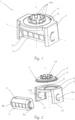
- the floor lighting module 1 shows a floor lighting module 1 for a motor vehicle 17 for generating a floor light distribution 2a, with which a subsurface can be illuminated laterally and/or underneath a motor vehicle 17.
- 2 shows an exploded view of the floor lighting module 1.
- the floor lighting module 1 is set up to adjust the floor light distribution 2a about a first axis z and a second axis x that differs from the first axis z.
- the floor lighting module 1 can be attached to a motor vehicle 17 .
- the floor lighting module 1 includes an illuminant 2 for generating the floor light distribution 2a. In the exemplary embodiment shown, the floor lighting module 1 has four lamps 2 which are arranged next to one another.
- the illuminant 2 can comprise a light source and a projection device assigned to the light source, the projection device being able to project light which can be generated by the light source as a ground light distribution 2a, for example onto a road surface.
- the floor lighting module 1 also includes a light source carrier 3, to which the light source 2 is attached, and a fastening device 4 for fastening the floor lighting module 1 to a motor vehicle 17.
- the floor lighting module 1 also has an adapter element 5, which is set up to adjust the floor light distribution 2a to allow for the first z and second axis x.
- the adapter element 5 is rotatably mounted on the fastening device 4 about the first axis z.
- the illuminant carrier 3 is fastened to the adapter element 5 in such a way that a rotational movement of the adapter element 5 about the first axis z causes the illuminant carrier 3 to rotate about the first axis z.
- the illuminant carrier 3 is in turn mounted on the adapter element 5 so that it can rotate about the second axis x.
- the first axis z and the second axis x are oriented essentially orthogonally to one another.
- the first axis z can be a vertical axis and the second axis x can be a horizontal axis.
- the first z-axis can be the vertically running z-axis in a Cartesian coordinate system.
- the second axis x can be the horizontally running x-axis in a Cartesian coordinate system, which is oriented parallel to the longitudinal axis of the motor vehicle 17 in a state in which the floor lighting module 1 is attached to a motor vehicle 17 .
- the adapter element 5 has a circular receiving opening 6 , the fastening device 4 having a receiving section 7 designed to complement the receiving opening 6 .
- the fastening device 4 is accommodated in the accommodation opening 6 via the accommodation section 7 .
- the fastening device 4 has a latching element 15 which is set up to fasten the floor lighting module 1 to a motor vehicle 17 via a latching connection.
- the latching element has a plurality of latching lugs 15a arranged in a circle relative to one another, which extend away from the receiving section 7 of the fastening device 4 essentially parallel to the first axis z.
- the receiving opening 6 has a holding section 8 and the fastening device 4 has a counter-section 9 corresponding to the holding section 8.
- the holding section 8 and the counter-section 9 are designed in relation to one another such that, in a receiving state, the receiving section 7 of the fastening device 4 is in the receiving opening 6 of the adapter element 5 is accommodated, the holding section 8 is engaged with the counter section 9 in such a way that the adapter element 5 is secured against movement along the first axis of rotation z.
- the adapter element 5 has at least one bulb holder holding area, the bulb holder holding area comprising a first holding leg 12 and a second holding leg 13 .
- the illuminant support 3 is held in a holding state between the first holding leg 12 and the second holding leg 13 in such a way that the illuminant support 3 is secured against movement along the second axis x.
- the illuminant carrier 3 is engaged with the first retaining leg 12 and the second retaining leg 13 in such a way that the illuminant carrier 3 about the second axis x is rotatable.
- the first holding leg 12 and the second holding leg 13 extend away from the holding section 8 of the adapter element 5, essentially along the first axis z.
- the first holding limb 12 has a first holding opening 12a and the second holding limb 13 has a second holding opening 13a, the illuminant carrier 3 having a first holding projection 3a and a second holding projection 3b.
- the first holding projection 3a is held in the first holding opening 12a and the second holding projection 3b in the second holding opening 13a in a form-fitting manner such that the illuminant carrier 3 can be rotated about the second axis x between the two holding legs 12, 13.
- the first holding opening 12a and the second holding opening 13a are formed as a curved or circular segment-shaped oblong hole.
- the circular receiving opening 6 has teeth 10 running at least in sections along its circumference radially to the first axis z.
- the teeth 10 are designed and set up to interact with a counter-element 11 .
- the counter-element 11 can be brought into engagement with the teeth 10 in such a way that a rotary movement about the first axis z that can be performed by the counter-element 11 can induce a rotary movement of the adapter element 5 relative to the fastening element 4 .
- the rotational movement that can be performed by the counter-element 11 induces, for example, a parallel rotational movement of the adapter element 5 relative to the fastening element 4.
- the fastening element 4 has an adjustment opening 14, via which the counter-element 11, for indicating the rotational movement on the adapter element 5, with the teeth running radially on the circumference 10 of the receiving opening 6 can be engaged.
- the rotary motion about the first axis z that can be performed by the counter-element 11 to indicate a rotary motion in the same direction on the adapter element 5 can, in particular, be carried out manually.
- the adapter element 5 preferably has a first fixing means (not shown), which is set up to fix a first angle of rotation by which the adapter element 5 can be rotated relative to the fastening device 3 .
- the adapter element 5 preferably has a second fixing means (not shown), which is set up to fix a second angle of rotation by which the illuminant carrier 3 can be rotated relative to the adapter element 4 .
- the illuminant carrier 3 is designed as a housing in which the illuminant 2 is accommodated.
- the illuminant carrier 3 has a holding projection 3a, 3b on each of two opposite side surfaces.
- Each holding projection 3a, 3b is designed in the shape of a segment of a circle.
- a grooved structure 16 is formed on the inner side of the circular segment-shaped retaining projection 3a, 3b, which can be brought into engagement with corresponding engagement elements on the retaining opening 12a, 13a of a retaining limb 12, 13 in order to fix the angle of rotation of the illuminant carrier 3 relative to a retaining limb 12, 13 .
- figure 5 shows the counter element 11 in a state in which it is accommodated in the insertion opening 14 of the fastening element 4 .
- the rotary motion that can be performed by the counter-element 11 induces a unidirectional rotary motion of the adapter element 5 relative to the fastening element 4.
- the counter-element 11 engages with the circumferentially radially running teeth 10 of the receiving opening 6 in order to transmit the rotary motion to the adapter element 5.
- the rotational movement about the first axis z that can be carried out by the counter-element 11 can, in particular, be carried out manually.
- the counter-element 11 is a screwdriver.
- Each floor lighting module 1 can generate one or more floor light distributions 2a, which can be adjusted or pivoted relative to the motor vehicle 17 via the mechanism described above.
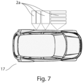
- FIG. 7 shows a motor vehicle 17 with three floor lighting modules 1, each floor lighting module 1 radiating different floor light distributions 2a to the side of the vehicle 17 onto a substrate.
- the three floor light distributions 2a can be adjusted relative to one another via the adapter elements 5 of the floor lighting modules 1 .
Abstract
Bodenbeleuchtungsmodul (1) für ein Kraftfahrzeug zur Erzeugung einer Boden-Lichtverteilung (2a), umfassend ein Leuchtmittel (2) zur Erzeugung der Boden-Lichtverteilung (2a), einen Leuchtmittelträger (3), eine Befestigungsvorrichtung (4) zur Befestigung des Bodenbeleuchtungsmoduls (1) an einem Kraftfahrzeug, ein Adapterelement (5), welches eingerichtet ist, die Verstellung der Boden-Lichtverteilung (2a) um eine erste Achse (z) und eine zweite Achse (x) zu ermöglichen, wobei das Adapterelement (5) eine Aufnahmeöffnung (6) aufweist, wobei die Befestigungsvorrichtung (4) einen zu der Aufnahmeöffnung komplementär ausgebildeten Aufnahmeabschnitt (7) aufweist, wobei die Aufnahmeöffnung (6) entlang ihres Umfangs radial zur ersten Achse (z) verlaufende Zähne (10) aufweist, wobei die Zähne (10) derart ausgestaltet und dazu eingerichtet sind, mit einem Gegenelement (11) zusammenzuwirken, wobei das Gegenelement (11) derart in Eingriff mit den Zähnen (10) bringbar ist, dass eine von dem Gegenelement (11) ausführbare Drehbewegung um die erste Achse (z) eine Drehbewegung des Adapterelements (5) relativ zu dem Befestigungselement (4) induzieren kann.Floor lighting module (1) for a motor vehicle for generating a floor light distribution (2a), comprising an illuminant (2) for generating the floor light distribution (2a), an illuminant support (3), a fastening device (4) for fastening the floor lighting module (1 ) on a motor vehicle, an adapter element (5) which is set up to enable the ground light distribution (2a) to be adjusted about a first axis (z) and a second axis (x), the adapter element (5) having a receiving opening ( 6), wherein the fastening device (4) has a receiving section (7) designed to complement the receiving opening, the receiving opening (6) having teeth (10) running along its circumference radially to the first axis (z), the teeth (10 ) are designed and set up to interact with a counter-element (11), wherein the counter-element (11) can be brought into engagement with the teeth (10) in such a way that a rotary movement about the first axis (e.g ) A rotational movement of the adapter element (5) relative to the fastening element (4) can induce.
Description
Die Erfindung betrifft ein Bodenbeleuchtungsmodul für ein Kraftfahrzeug zur Erzeugung einer Boden-Lichtverteilung, mit welcher ein Untergrund seitlich und/oder unterhalb eines Kraftfahrzeugs beleuchtbar ist, wobei das Bodenbeleuchtungsmodul eingerichtet ist, die Boden-Lichtverteilung, um eine erste und eine von der ersten unterschiedliche zweite Achse, zu verstellen, wobei das Bodenbeleuchtungsmodul an einem Kraftfahrzeug befestigbar ist, wobei das Bodenbeleuchtungsmodul Folgendes umfasst:
- ein Leuchtmittel zur Erzeugung der Boden-Lichtverteilung,
- einen Leuchtmittelträger, an welchem das Leuchtmittel befestigt ist,
- eine Befestigungsvorrichtung zur Befestigung des Bodenbeleuchtungsmoduls an einem Kraftfahrzeug,
- ein Adapterelement, welches eingerichtet ist, die Verstellung der Boden-Lichtverteilung um die erste und die zweite Achse zu ermöglichen, wobei das Adapterelement an der Befestigungsvorrichtung drehbar um die erste Achse gelagert ist, wobei der Leuchtmittelträger an dem Adapterelement derart befestigt ist, dass eine Drehbewegung des Adapterelements um die erste Achse eine Drehung des Leuchtmittelträgers um die erste Achse bewirkt, und wobei der Leuchtmittelträger an dem Adapterelement drehbar um die zweite Achse gelagert ist.
- a lamp to generate the floor light distribution,
- a light source carrier to which the light source is attached,
- a fastening device for fastening the floor lighting module to a motor vehicle,
- an adapter element which is set up to enable the ground light distribution to be adjusted about the first and the second axis, the adapter element being mounted on the fastening device so as to be rotatable about the first axis, the illuminant carrier being fastened to the adapter element in such a way that a rotary movement of the adapter element causes the illuminant carrier to rotate about the first axis about the first axis, and wherein the illuminant carrier is mounted on the adapter element so that it can rotate about the second axis.
Die Erfindung betrifft weiters ein System, umfassend zumindest zwei Bodenbeleuchtungsmodule.The invention further relates to a system comprising at least two floor lighting modules.
Die Erfindung betrifft ferner ein Kraftfahrzeug, umfassend zumindest ein Bodenbeleuchtungsmodul oder ein System umfassend zumindest zwei Bodenbeleuchtungsmodule.The invention also relates to a motor vehicle comprising at least one floor lighting module or a system comprising at least two floor lighting modules.
Im Stand der Technik sind verstellbare Bodenbeleuchtungsmodule bekannt. Ein Bodenbeleuchtungsmodul erzeugt üblicherweise eine Boden-Lichtverteilung bzw. ein Lichtbild, welches einen Untergrund seitlich eines Kraftfahrzeugs, an welchem das Bodenbeleuchtungsmodul befestigt ist, beleuchtet. Die Einstellung bzw. die Verstellung der Boden-Lichtverteilung relativ zu dem Kraftfahrzeug erfolgt im Stand der Technik meist über Elektromotoren, welche eine die Bodenlichtverteilung erzeugende Lichtquelle des Bodenbeleuchtungsmoduls innerhalb eines Gehäuses des Bodenbeleuchtungsmoduls verschwenken. Die im Stand der Technik bekannten Einstellmechanismen sind jedoch oft fehleranfällig bzw. in der Herstellung teuer.Adjustable floor lighting modules are known in the prior art. A floor lighting module usually generates a floor light distribution or a Light image that illuminates a surface on the side of a motor vehicle to which the floor lighting module is attached. In the prior art, the setting or adjustment of the floor light distribution relative to the motor vehicle is usually carried out using electric motors, which pivot a light source of the floor lighting module that generates the floor light distribution within a housing of the floor lighting module. However, the adjustment mechanisms known in the prior art are often error-prone or expensive to manufacture.
Die Aufgabe der vorliegenden Erfindung besteht darin, die Nachteile des Standes der Technik zu lindern bzw. zu beseitigen. Die Erfindung setzt sich daher insbesondere zum Ziel, ein Bodenbeleuchtungsmodul mit einem verbesserten Einstellmechanismus zu schaffen.The object of the present invention is to alleviate or eliminate the disadvantages of the prior art. The invention therefore aims in particular to create a floor lighting module with an improved adjustment mechanism.
Diese Aufgabe wird durch ein Bodenbeleuchtungsmodul mit den Merkmalen von Anspruch 1 gelöst. Bevorzugte Ausführungen sind in den abhängigen Ansprüchen angegeben.This object is achieved by a floor lighting module having the features of
Erfindungsgemäß weist das Adapterelement eine kreisrunde Aufnahmeöffnung auf, wobei die Befestigungsvorrichtung einen zu der Aufnahmeöffnung komplementär ausgebildeten Aufnahmeabschnitt aufweist, wobei die Befestigungsvorrichtung über den Aufnahmeabschnitt in der Aufnahmeöffnung aufgenommen ist,
wobei die Aufnahmeöffnung einen Halteabschnitt und die Befestigungsvorrichtung einen zu dem Halteabschnitt korrespondieren Gegenabschnitt aufweist, wobei der Halteabschnitt und der Gegenabschnitt derart zueinander ausgebildet sind, dass, in einem Aufnahmezustand, in dem der Aufnahmeabschnitt der Befestigungsvorrichtung in der Aufnahmeöffnung desAccording to the invention, the adapter element has a circular receiving opening, the fastening device having a receiving section designed to complement the receiving opening, the fastening device being received in the receiving opening via the receiving section,
wherein the receiving opening has a holding section and the fastening device has a counter-section that corresponds to the holding section, wherein the holding section and the counter-section are configured in relation to one another such that, in a receiving state in which the receiving section of the fastening device is in the receiving opening of the
Adapterelements aufgenommen ist, der Halteabschnitt mit dem Gegenabschnitt derart in Eingriff ist, dass das Adapterelement gegen eine Bewegung entlang der ersten Drehachse gesichert ist,
wobei die kreisrunde Aufnahmeöffnung entlang ihres Umfangs zumindest abschnittweise radial zur ersten Achse verlaufende Zähne aufweist, wobei die Zähne derart ausgestaltet und dazu eingerichtet sind, mit einem Gegenelement zusammenzuwirken, wobei das Gegenelement derart in Eingriff mit den Zähnen bringbar ist, sodass eine von dem Gegenelement ausführbare Drehbewegung um die erste Achse eine Drehbewegung des Adapterelements relativ zu dem Befestigungselement induzieren kann.adapter element is accommodated, the holding section engages with the counter-section in such a way that the adapter element is secured against movement along the first axis of rotation,
wherein the circular receiving opening has teeth running radially to the first axis at least in sections along its circumference, wherein the teeth are designed and set up to interact with a counter-element, wherein the counter-element can be brought into engagement with the teeth in such a way that one of the counter-element executable Rotational movement about the first axis can induce rotational movement of the adapter element relative to the fastening element.
Dadurch ergibt sich der Vorteil, dass die Verstellung der Boden-Lichtverteilung um die erste und die zweite Achse besonders einfach erfolgen kann. Durch die Verstellung bzw. Verschwenkung des Leuchtmittelträgers um die erste und zweite Achse kann die Position der Boden-Lichtverteilung relativ zu einem Kraftfahrzeug, an welchem das Bodenbeleuchtungsmodul befestigt sein kann, verstellt bzw. verschwenkt werden. Die Aufnahmeöffnung des Adapterelement und der Aufnahmeabschnitt der Befestigungsvorrichtung sind insbesondere über eine Drehkranz-Verbindung miteinander verbunden, bzw. kann die Übertragung der Drehbewegung des Gegenelements auf das Adapterelement über die Drehkranz-Verbindung erfolgen. Dadurch ergibt sich der Vorteil, dass die Drehung des Adapterelements relativ zu der Befestigungsvorrichtung besonders einfach und gut steuerbar erfolgen kann. Das Bodenbeleuchtungsmodul ist insbesondere an einer Unterseite eines Kraftfahrzeugs befestigbar.This results in the advantage that the ground light distribution can be adjusted particularly easily about the first and the second axis. By adjusting or pivoting the illuminant carrier about the first and second axis, the position of the ground light distribution can be adjusted or pivoted relative to a motor vehicle to which the ground lighting module can be attached. The receiving opening of the adapter element and the receiving section of the fastening device are connected to one another in particular via a slewing ring connection, or the rotary movement of the counter-element can be transmitted to the adapter element via the slewing ring connection. This results in the advantage that the adapter element can be rotated relative to the fastening device in a particularly simple and easily controllable manner. The floor lighting module can be fastened in particular to an underside of a motor vehicle.
Es kann vorgesehen sein, dass die von dem Gegenelement ausführbare Drehbewegung eine gleichgerichtete Drehbewegung des Adapterelements relativ zu dem Befestigungselement induzieren kann.It can be provided that the rotary movement that can be performed by the counter-element can induce a rotary movement of the adapter element in the same direction relative to the fastening element.
Es kann vorgesehen sein, dass das Adapterelement zumindest einen Leuchtmittelträger-Haltebereich aufweist, wobei der Leuchtmittelträger-Haltebereich einen ersten Halteschenkel und einen zweiten Halteschenkel aufweist, wobei der Leuchtmittelträger, in einem Haltezustand, zwischen dem ersten Halteschenkel und dem zweiten Halteschenkel derart gehalten wird, dass der Leuchtmittelträger gegen eine Bewegung entlang der zweiten Achse gesichert ist, wobei in dem Haltezustand der Leuchtmittelträger mit dem ersten Halteschenkel und dem zweiten Halteschenkel derart in Eingriff ist, dass der Leuchtmittelträger um die zweite Achse drehbar ist. Der erste Haltschenkel und der zweite Halteschenkel sind vorzugsweise an einem Randbereich um die Aufnahmeöffnung angeordnet. Vorzugsweise sind die beiden Halteschenkel diametral an der Aufnahmeöffnung angeordnet. Das Adapterelement kann eine Grundplatte aufweisen, welche die Aufnahmeöffnung aufweist, wobei sich die beiden Aufnahmeschenkel von der Grundplatte, im Wesentlichen parallel zur ersten Achse, weg erstrecken.Provision can be made for the adapter element to have at least one illuminant carrier holding area, with the illuminant carrier holding area having a first holding leg and a second holding leg, with the illuminant carrier being held in a holding state between the first holding leg and the second holding leg in such a way that the illuminant support is secured against movement along the second axis, wherein in the holding state the illuminant support is in engagement with the first holding leg and the second holding leg such that the illuminant support is rotatable about the second axis. The first holding leg and the second holding leg are preferably arranged on an edge region around the receiving opening. The two holding legs are preferably arranged diametrically on the receiving opening. The adapter element can have a base plate which has the receiving opening, with the two receiving legs extending away from the base plate, essentially parallel to the first axis.
Es kann vorgesehen sein, dass sich der erste Halteschenkel und der zweite Halteschenkel von dem Halteabschnitt des Adapterelements, im Wesentlich entlang der ersten Achse, weg erstrecken.Provision can be made for the first holding leg and the second holding leg to extend away from the holding section of the adapter element, essentially along the first axis.
Es kann vorgesehen sein, dass der erste Halteschenkel eine erste Halteöffnung und der zweite Halteschenkel eine zweite Halteöffnung aufweist, wobei der Leuchtmittelträger einen ersten Haltevorsprung und einen zweiten Haltevorsprung aufweist, wobei in dem Haltezustand der erste Haltevorsprung in der ersten Halteöffnung und der zweite Haltevorsprung in der zweiten Halteöffnung derart formschlüssig aufgenommen ist, dass der Leuchtmittelträger zwischen den beiden Halteschenkeln um die zweite Achse drehbar ist. Eine Positionsänderung der Haltvorsprünge innerhalb der Halteöffnung kann die Drehung des Leuchtmittelträgers um zweite Achse induzieren. Vorzugsweise sind die erste Halteöffnung und die zweite Halteöffnung als kreissegment-förmiges Langloch ausgestaltet. Die erste Halteöffnung und die zweite Haltöffnung sind vorzugsweise gleichartig ausgestaltet. Der erste Haltvorsprung und der zweite Haltevorsprung sind vorzugsweise gleichartig ausgestaltet. Der erste Haltvorsprung und der zweite Haltevorsprung sind insbesondere zu der ersten und zweiten Halteöffnung korrespondierend ausgestaltet.Provision can be made for the first holding leg to have a first holding opening and the second holding leg to have a second holding opening, with the illuminant carrier having a first holding projection and a second holding projection, with the first holding projection being in the first holding opening and the second holding projection being in the second holding opening is received in a form-fitting manner in such a way that the illuminant carrier can be rotated about the second axis between the two holding legs. A change in the position of the holding projections within the holding opening can induce the rotation of the illuminant carrier about the second axis. The first holding opening and the second holding opening are preferably configured as a slot in the shape of a segment of a circle. The first holding opening and the second holding opening are preferably designed in the same way. The first retaining projection and the second retaining projection are preferably designed in the same way. The first retaining projection and the second retaining projection are designed to correspond in particular to the first and second retaining opening.
Es kann vorgesehen sein, dass das Befestigungselement eine Einstellöffnung aufweist, über welche das Gegenelement, zur Indizierung der Drehbewegung auf das Adapterelement, mit den umfangseitig radial verlaufenden Zähnen der Aufnahmeöffnung in Eingriff gebracht werden kann. Das Gegenelement kann beispielsweise ein Schraubenzieher sein.Provision can be made for the fastening element to have an adjustment opening, via which the counter-element can be brought into engagement with the circumferentially radially running teeth of the receiving opening in order to indicate the rotational movement on the adapter element. The counter-element can be a screwdriver, for example.
Es kann vorgesehen sein, dass die erste Achse und die zweite Achse im Wesentlichen orthogonal zueinander orientiert sind.Provision can be made for the first axis and the second axis to be oriented essentially orthogonally to one another.
Es kann vorgesehen sein, dass in einem Zustand, in dem das Bodenbeleuchtungsmodul an einem Kraftfahrzeug angebracht ist, die erste Achse im Wesentlichen vertikal und die zweite Achse im Wesentlichen horizontal orientiert ist.It can be provided that in a state in which the floor lighting module is attached to a motor vehicle, the first axis is oriented essentially vertically and the second axis is oriented essentially horizontally.
Es kann vorgesehen sein, dass das Adapterelement ein erstes Fixiermittel aufweist, welches dazu eingerichtet ist, einen ersten Drehwinkel, um welchen das Adapterelement relativ zu der Befestigungsvorrichtung drehbar ist, zu fixieren.Provision can be made for the adapter element to have a first fixing means which is set up to fix a first angle of rotation by which the adapter element can be rotated relative to the fastening device.
Es kann vorgesehen sein, dass das Adapterelement ein zweites Fixiermittel aufweist, welches dazu eingerichtet ist, einen zweiten Drehwinkel, um welchen der Leuchtmittelträger relativ zu dem Adapterelement drehbar ist, zu fixieren.Provision can be made for the adapter element to have a second fixing means which is set up to fix a second angle of rotation by which the illuminant carrier can be rotated relative to the adapter element.
Es kann vorgesehen sein, dass die von dem Gegenelement ausführbare Drehbewegung um die erste Achse, zur Indizierung einer gleichgerichteten Drehbewegung auf des Adapterelement, manuell erfolgen kann. Die Drehbewegung des Gegenelements kann händisch, insbesondere ohne einem mechanischen oder elektrischen Antriebsmittel, ausgeführt werden.Provision can be made for the rotational movement about the first axis, which can be carried out by the counter-element, to be carried out manually in order to indicate a rotational movement in the same direction on the adapter element. The rotary movement of the counter-element can be carried out manually, in particular without a mechanical or electrical drive means.
Es kann vorgesehen sein, dass die Befestigungsvorrichtung ein Rastelement aufweist, welches dazu eingerichtet ist, das Bodenbeleuchtungsmodul über eine Rastverbindung an einem Kraftfahrzeug zu befestigen.Provision can be made for the fastening device to have a latching element which is set up to fasten the floor lighting module to a motor vehicle via a latching connection.
Es kann vorgesehen sein, dass das Rastelement zumindest eine Rastnase, vorzugsweise mehrere Rastnasen, aufweist, welche sich von dem Aufnahmeabschnitt der Befestigungsvorrichtung im Wesentlichen parallel zur ersten Achse weg erstrecken.Provision can be made for the latching element to have at least one latching lug, preferably a plurality of latching lugs, which extend away from the receiving section of the fastening device essentially parallel to the first axis.
Es kann ein System, umfassend zumindest zwei Bodenbeleuchtungsmodule, vorgesehen sein, wobei ein erstes Bodenbeleuchtungsmodul zur Erzeugung einer ersten Boden-Lichtverteilung und ein zweites Bodenbeleuchtungsmodul zur Erzeugung einer zweiten Boden-Lichtverteilung eingerichtet ist, wobei vorzugsweise die erste Boden-Lichtverteilung und die zweite Boden-Lichtverteilung unterschiedlich ausgestaltet sind.A system comprising at least two floor lighting modules can be provided, with a first floor lighting module being set up to generate a first floor light distribution and a second floor lighting module being set up to generate a second floor light distribution, with the first floor light distribution and the second floor light distribution preferably being Light distribution are designed differently.
Es kann ein Kraftfahrzeug, umfassend zumindest ein Bodenbeleuchtungsmodul oder ein System, vorgesehen sein. Das Bodenbeleuchtungsmodul ist insbesondere an einer Unterseite des Kraftfahrzeugs befestigt.A motor vehicle comprising at least one floor lighting module or a system can be provided. The floor lighting module is attached in particular to an underside of the motor vehicle.
Im Rahmen dieser Beschreibung sind die Begriffe "oben", "unten", "horizontal", "vertikal" als Angaben der Ausrichtung zu verstehen, wenn das Bodenbeleuchtungsmodul in normaler Benutzungsstellung angeordnet ist, nachdem es an einem Kraftfahrzeug, insbesondere an einer Unterseite eines Kraftfahrzeugs, befestigt wurde.In the context of this description, the terms "top", "bottom", "horizontal", "vertical" are to be understood as indications of the orientation when the floor lighting module is arranged in the normal use position after it has been attached to a motor vehicle, in particular to the underside of a motor vehicle , has been attached.
Die Erfindung wird nachstehend anhand eines bevorzugten Ausführungsbeispiels, auf das sie jedoch nicht beschränkt sein soll, noch weiter erläutert. In den Zeichnungen zeigt:
-
Fig. 1 ein erfindungsgemäßes Bodenbeleuchtungsmodul; -
Fig. 2 eine Explosionsdarstellung des Bodenbeleuchtungsmoduls gemäßFig. 1 ; -
Fig. 3 eine Detailansicht des Bodenbeleuchtungsmoduls gemäßFig. 1 ; -
Fig. 4 eine Detailansicht eines Leuchtmittelträgers; -
Fig. 5 eine Ansicht eines Einstellvorgangs des Bodenbeleuchtungsmoduls gemäßFig. 1 ; -
Fig. 6 ein Kraftfahrzeug mit drei Bodenbeleuchtungsmodulen; und -
Fig. 7 ein Kraftfahrzeug mit seitlichen Boden-Lichtverteilungen.
-
1 a floor lighting module according to the invention; -
2 an exploded view of the floor lighting module according to1 ; -
3 a detailed view of the floor lighting module according to FIG1 ; -
4 a detailed view of a light source carrier; -
figure 5 a view of an adjustment process of the floor lighting module according to FIG1 ; -
6 a motor vehicle with three floor lighting modules; and -
7 a motor vehicle with lateral ground light distributions.
Das Adapterelement 5 hat eine kreisrunde Aufnahmeöffnung 6, wobei die Befestigungsvorrichtung 4 einen zu der Aufnahmeöffnung 6 komplementär ausgebildeten Aufnahmeabschnitt 7 hat. Die Befestigungsvorrichtung 4 ist über den Aufnahmeabschnitt 7 in der Aufnahmeöffnung 6 aufgenommen.The
Die Befestigungsvorrichtung 4 weist ein Rastelement 15 auf, welches dazu eingerichtet ist, das Bodenbeleuchtungsmodul 1 über eine Rastverbindung an einem Kraftfahrzeug 17 zu befestigen. In dem gezeigten Ausführungsbeispiel hat das Rastelement mehrere kreisförmig zueinander angeordnete Rastnasen 15a, welche sich von dem Aufnahmeabschnitt 7 der Befestigungsvorrichtung 4 im Wesentlichen parallel zur ersten Achse z weg erstrecken.The
Die Aufnahmeöffnung 6 hat einen Halteabschnitt 8 und die Befestigungsvorrichtung 4 hat einen zu dem Halteabschnitt 8 korrespondieren Gegenabschnitt 9. Der Halteabschnitt 8 und der Gegenabschnitt 9 sind derart zueinander ausgebildet, dass, in einem Aufnahmezustand, in dem der Aufnahmeabschnitt 7 der Befestigungsvorrichtung 4 in der Aufnahmeöffnung 6 des Adapterelements 5 aufgenommen ist, der Halteabschnitt 8 mit dem Gegenabschnitt 9 derart in Eingriff ist, dass das Adapterelement 5 gegen eine Bewegung entlang der ersten Drehachse z gesichert ist.The receiving
Das Adapterelement 5 hat zumindest einen Leuchtmittelträger-Haltebereich, wobei der Leuchtmittelträger-Haltebereich einen ersten Halteschenkel 12 und einen zweiten Halteschenkel 13 umfasst. Der Leuchtmittelträger 3 wird in einem Haltezustand zwischen dem ersten Halteschenkel 12 und dem zweiten Halteschenkel 13 derart gehalten, dass der Leuchtmittelträger 3 gegen eine Bewegung entlang der zweiten Achse x gesichert ist. In dem Haltezustand ist der Leuchtmittelträger 3 mit dem ersten Halteschenkel 12 und dem zweiten Halteschenkel 13 derart in Eingriff, dass der Leuchtmittelträger 3 um die zweite Achse x drehbar ist. Der erste Halteschenkel 12 und der zweite Halteschenkel 13 erstrecken sich von dem Halteabschnitt 8 des Adapterelements 5, im Wesentlich entlang der ersten Achse z, weg.The
Der erste Halteschenkel 12 hat eine erste Halteöffnung 12a und der zweite Halteschenkel 13 hat eine zweite Halteöffnung 13a, wobei der Leuchtmittelträger 3 einen ersten Haltevorsprung 3a und einen zweiten Haltevorsprung 3b hat. Im Haltezustand ist der erste Haltevorsprung 3a in der ersten Halteöffnung 12a und der zweite Haltevorsprung 3b in der zweiten Halteöffnung 13a derart formschlüssig aufgenommen, dass der Leuchtmittelträger 3 zwischen den beiden Halteschenkeln 12, 13 um die zweite Achse x drehbar ist. Die erste Halteöffnung 12a und die zweite Haltöffnung 13a sind als gekrümmt bzw. kreissegmentförmig verlaufendes Langloch ausgebildet.The
Wie in
Das Adapterelement 5 hat vorzugsweise ein erstes Fixiermittel (nicht gezeigt), welches dazu eingerichtet ist, einen ersten Drehwinkel, um welchen das Adapterelement 5 relativ zu der Befestigungsvorrichtung 3 drehbar ist, zu fixieren. Das Adapterelement 5 hat vorzugsweise ein zweites Fixiermittel (nicht gezeigt), welches dazu eingerichtet ist, einen zweiten Drehwinkel, um welchen der Leuchtmittelträger 3 relativ zu dem Adapterelement 4 drehbar ist, zu fixieren.The
Claims (15)
Priority Applications (3)
| Application Number | Priority Date | Filing Date | Title |
|---|---|---|---|
| EP21217000.5A EP4201743A1 (en) | 2021-12-22 | 2021-12-22 | Floor lighting module for a motor vehicle for generating floor lighting distribution |
| KR1020220171181A KR20230095815A (en) | 2021-12-22 | 2022-12-09 | Floor lighting module for a motor vehicle for generating a floor light distribution |
| CN202211652942.9A CN116412382A (en) | 2021-12-22 | 2022-12-22 | Floor lighting module for a motor vehicle for generating a floor light distribution |
Applications Claiming Priority (1)
| Application Number | Priority Date | Filing Date | Title |
|---|---|---|---|
| EP21217000.5A EP4201743A1 (en) | 2021-12-22 | 2021-12-22 | Floor lighting module for a motor vehicle for generating floor lighting distribution |
Publications (1)
| Publication Number | Publication Date |
|---|---|
| EP4201743A1 true EP4201743A1 (en) | 2023-06-28 |
Family
ID=79021023
Family Applications (1)
| Application Number | Title | Priority Date | Filing Date |
|---|---|---|---|
| EP21217000.5A Pending EP4201743A1 (en) | 2021-12-22 | 2021-12-22 | Floor lighting module for a motor vehicle for generating floor lighting distribution |
Country Status (3)
| Country | Link |
|---|---|
| EP (1) | EP4201743A1 (en) |
| KR (1) | KR20230095815A (en) |
| CN (1) | CN116412382A (en) |
Citations (5)
| Publication number | Priority date | Publication date | Assignee | Title |
|---|---|---|---|---|
| US4809137A (en) * | 1987-07-24 | 1989-02-28 | Kiyoshi Yamada | Back-mirror fitted with illumination light at car side |
| JP4619278B2 (en) * | 2005-11-25 | 2011-01-26 | 富士通テン株式会社 | Smart entry system for vehicle and lighting device for vehicle |
| DE102014007313A1 (en) * | 2014-05-17 | 2015-11-19 | Audi Ag | Device for assisting a driver of a motor vehicle when maneuvering and / or parking, associated motor vehicle and operating method |
| DE102015006656A1 (en) * | 2015-05-22 | 2016-03-31 | Daimler Ag | Fastening element for a trim part of a vehicle, trim part and vehicle |
| US20190163196A1 (en) * | 2017-11-28 | 2019-05-30 | Postmates Inc. | Light Projection System |
-
2021
- 2021-12-22 EP EP21217000.5A patent/EP4201743A1/en active Pending
-
2022
- 2022-12-09 KR KR1020220171181A patent/KR20230095815A/en unknown
- 2022-12-22 CN CN202211652942.9A patent/CN116412382A/en active Pending
Patent Citations (5)
| Publication number | Priority date | Publication date | Assignee | Title |
|---|---|---|---|---|
| US4809137A (en) * | 1987-07-24 | 1989-02-28 | Kiyoshi Yamada | Back-mirror fitted with illumination light at car side |
| JP4619278B2 (en) * | 2005-11-25 | 2011-01-26 | 富士通テン株式会社 | Smart entry system for vehicle and lighting device for vehicle |
| DE102014007313A1 (en) * | 2014-05-17 | 2015-11-19 | Audi Ag | Device for assisting a driver of a motor vehicle when maneuvering and / or parking, associated motor vehicle and operating method |
| DE102015006656A1 (en) * | 2015-05-22 | 2016-03-31 | Daimler Ag | Fastening element for a trim part of a vehicle, trim part and vehicle |
| US20190163196A1 (en) * | 2017-11-28 | 2019-05-30 | Postmates Inc. | Light Projection System |
Also Published As
| Publication number | Publication date |
|---|---|
| KR20230095815A (en) | 2023-06-29 |
| CN116412382A (en) | 2023-07-11 |
Similar Documents
| Publication | Publication Date | Title |
|---|---|---|
| DE102012211877B4 (en) | Device for handling a wind turbine rotor blade | |
| EP3847413B1 (en) | Wheel clamp | |
| DE10044213A1 (en) | Projector ceiling mount has adjustable arms fits most types is easy to adjust by ball joint | |
| DE2630181C3 (en) | Device for pivoting an object pivotably mounted in two planes at right angles to one another | |
| EP0230236A1 (en) | Apparatus for positioning data display units | |
| EP3561364A1 (en) | Device for adjusting a camera angle and use of such a device | |
| EP4201743A1 (en) | Floor lighting module for a motor vehicle for generating floor lighting distribution | |
| EP2553328B1 (en) | Mast attachment means for street lights | |
| DE2503075A1 (en) | LAMP | |
| DE202012104544U1 (en) | Downlight | |
| EP3604897B1 (en) | Mounting light, mounting system of a mounting light and light for same | |
| DE202008000857U1 (en) | Swivel recessed light | |
| DE202017107525U1 (en) | reading light | |
| DE102016215571A1 (en) | Mounting arrangement of an electric motor and seat | |
| DE102011121438A1 (en) | Device for holding housing of planetary gear box in e.g. wind energy plant, has adapters arranged at opposite sides of component and fastenable in region of center of gravity plane through component, where carriers co-operate with adapters | |
| EP0564833B1 (en) | Means for locking a dental articulator | |
| EP3815205A1 (en) | Mounting aid | |
| DE1605696B2 (en) | Device for mounting a vehicle tire on a rim | |
| EP2602542A1 (en) | Lighting Device | |
| DE19511584C2 (en) | Ring trough compulsory mixer | |
| DE102018114148A1 (en) | sharpener | |
| DE102019132106B4 (en) | Screw connection device for the mechanical connection of a front drum and a rear drum of a compressor of a gas turbine engine | |
| DE4321708A1 (en) | Radiator bracket | |
| DE2144784A1 (en) | AWNING | |
| DE19961260C2 (en) | Fastening device for fastening a sensor |
Legal Events
| Date | Code | Title | Description |
|---|---|---|---|
| PUAI | Public reference made under article 153(3) epc to a published international application that has entered the european phase |
Free format text: ORIGINAL CODE: 0009012 |
|
| STAA | Information on the status of an ep patent application or granted ep patent |
Free format text: STATUS: THE APPLICATION HAS BEEN PUBLISHED |
|
| AK | Designated contracting states |
Kind code of ref document: A1 Designated state(s): AL AT BE BG CH CY CZ DE DK EE ES FI FR GB GR HR HU IE IS IT LI LT LU LV MC MK MT NL NO PL PT RO RS SE SI SK SM TR |
|
| STAA | Information on the status of an ep patent application or granted ep patent |
Free format text: STATUS: REQUEST FOR EXAMINATION WAS MADE |
|
| 17P | Request for examination filed |
Effective date: 20231211 |
|
| RBV | Designated contracting states (corrected) |
Designated state(s): AL AT BE BG CH CY CZ DE DK EE ES FI FR GB GR HR HU IE IS IT LI LT LU LV MC MK MT NL NO PL PT RO RS SE SI SK SM TR |