EP4179934A1 - Jar with a tool holder, a wall component and a cooler element, and blender with such jar - Google Patents
Jar with a tool holder, a wall component and a cooler element, and blender with such jar Download PDFInfo
- Publication number
- EP4179934A1 EP4179934A1 EP21208481.8A EP21208481A EP4179934A1 EP 4179934 A1 EP4179934 A1 EP 4179934A1 EP 21208481 A EP21208481 A EP 21208481A EP 4179934 A1 EP4179934 A1 EP 4179934A1
- Authority
- EP
- European Patent Office
- Prior art keywords
- jar
- cooler element
- tool holder
- wall component
- blender
- Prior art date
- Legal status (The legal status is an assumption and is not a legal conclusion. Google has not performed a legal analysis and makes no representation as to the accuracy of the status listed.)
- Pending
Links
- 235000013305 food Nutrition 0.000 claims abstract description 48
- 238000001816 cooling Methods 0.000 description 4
- 239000012782 phase change material Substances 0.000 description 2
- 235000013570 smoothie Nutrition 0.000 description 2
- OQCFWECOQNPQCG-UHFFFAOYSA-N 1,3,4,8-tetrahydropyrimido[4,5-c]oxazin-7-one Chemical compound C1CONC2=C1C=NC(=O)N2 OQCFWECOQNPQCG-UHFFFAOYSA-N 0.000 description 1
- XSQUKJJJFZCRTK-UHFFFAOYSA-N Urea Chemical compound NC(N)=O XSQUKJJJFZCRTK-UHFFFAOYSA-N 0.000 description 1
- 230000000712 assembly Effects 0.000 description 1
- 238000000429 assembly Methods 0.000 description 1
- 239000004202 carbamide Substances 0.000 description 1
- 235000020965 cold beverage Nutrition 0.000 description 1
- 230000001419 dependent effect Effects 0.000 description 1
- 238000007710 freezing Methods 0.000 description 1
- 230000008014 freezing Effects 0.000 description 1
- 238000002360 preparation method Methods 0.000 description 1
- 150000003839 salts Chemical class 0.000 description 1
- XLYOFNOQVPJJNP-UHFFFAOYSA-N water Substances O XLYOFNOQVPJJNP-UHFFFAOYSA-N 0.000 description 1
Images

Classifications
-
- A—HUMAN NECESSITIES
- A47—FURNITURE; DOMESTIC ARTICLES OR APPLIANCES; COFFEE MILLS; SPICE MILLS; SUCTION CLEANERS IN GENERAL
- A47J—KITCHEN EQUIPMENT; COFFEE MILLS; SPICE MILLS; APPARATUS FOR MAKING BEVERAGES
- A47J43/00—Implements for preparing or holding food, not provided for in other groups of this subclass
- A47J43/04—Machines for domestic use not covered elsewhere, e.g. for grinding, mixing, stirring, kneading, emulsifying, whipping or beating foodstuffs, e.g. power-driven
- A47J43/07—Parts or details, e.g. mixing tools, whipping tools
- A47J43/0727—Mixing bowls
-
- A—HUMAN NECESSITIES
- A23—FOODS OR FOODSTUFFS; TREATMENT THEREOF, NOT COVERED BY OTHER CLASSES
- A23G—COCOA; COCOA PRODUCTS, e.g. CHOCOLATE; SUBSTITUTES FOR COCOA OR COCOA PRODUCTS; CONFECTIONERY; CHEWING GUM; ICE-CREAM; PREPARATION THEREOF
- A23G9/00—Frozen sweets, e.g. ice confectionery, ice-cream; Mixtures therefor
- A23G9/04—Production of frozen sweets, e.g. ice-cream
- A23G9/08—Batch production
- A23G9/12—Batch production using means for stirring the contents in a non-moving container
-
- A—HUMAN NECESSITIES
- A47—FURNITURE; DOMESTIC ARTICLES OR APPLIANCES; COFFEE MILLS; SPICE MILLS; SUCTION CLEANERS IN GENERAL
- A47J—KITCHEN EQUIPMENT; COFFEE MILLS; SPICE MILLS; APPARATUS FOR MAKING BEVERAGES
- A47J43/00—Implements for preparing or holding food, not provided for in other groups of this subclass
- A47J43/04—Machines for domestic use not covered elsewhere, e.g. for grinding, mixing, stirring, kneading, emulsifying, whipping or beating foodstuffs, e.g. power-driven
- A47J43/07—Parts or details, e.g. mixing tools, whipping tools
Definitions
- the present invention concerns a jar comprising a tool holder, a wall component and a cooler element.
- the invention further concerns a (stationary) blender with a base and such jar.
- Conventional blenders are devised for domestic use and typically comprise a jar and a base.
- the jar usually is composed of a knife holder configured to hold a blade assembly and forming a bottom of the jar, and a wall component detachably combinable to the knife holder so as to form the jar.
- the base comprises an electric motor and defines an operation position for the jar. In this position of the jar, the blade assembly held by the knife holder is coupled to the electric motor which thus is adapted to rotate the blade assembly. Thereby, food may be chopped, mixed and/or liquefied.
- a jar according to the present invention belongs to a blender or is configured to form part of a blender.
- the jar comprises a tool holder, a wall component and a cooler element, which are detachably combinable.
- a combined state i.e., when the jar has been assembled, they together define a food reception space of the jar, the food reception space designated to receive food to be processed by the blender (in particular, by a tool the tool holder may hold).
- the cooler element i.e., a surface thereof at least partially delimits the food reception space.
- a blender according to the present invention comprises a jar according to an embodiment of the present invention, and a base defining an operation position of the jar and comprising an electric motor.
- the electric motor is coupled with a tool when this is (preferably detachably) fixed to the tool holder.
- the cooler element is designated to be put - prior to its utilisation - in a cooling environment such as a household refrigerator or a domestic freezer, and thus may be cooled therefrom.
- a cooling environment such as a household refrigerator or a domestic freezer
- the present invention thus facilitates that, if the cooler element has recently been taken out of the cooling environment before assembling and using the jar (along with a base of the blender), the temperature of the food being processed may be lowered due to its contact with the cooler element. Therefore, the present invention provides a convenient and easily employable passive cooling means for preparing, in a domestic environment, cool stirred and/or ground food such as frosty smoothies.
- the cooler element may comprise one or more double-walled regions including a chamber which may contain a solution (such as salt water and/or urea) freezing at a temperature below 0°C.
- the cooler element may preferably contain a latent heat accumulator which can comprise a phase change material.
- the cooler element is ring-shaped.
- the tool holder, the wall component and/or the cooler element may comprise means for a frictional connection (e.g., a (respective) screw thread) and/or means for a form-fit connection (such as at least one snap-lock means and/or at least one bayonet joint), which respectively may provide for detachably combining said components.
- the wall component, the cooler element and/or the tool holder may respectively comprise at least one fixation element (such as a pin, a screw thread and/or a cavity) configured to engage with at least one fixation element (such as a pin, a screw thread and/or a cavity) of a respective other one of the wall component, the cooler element and/or the tool holder.
- the cooler element at least partially delimits the food reception space in a bottom region thereof.
- it may at least partially delimit a lowest third or even a lowest fourth of the food reception space; in this document, the terms "bottom” and "low” and its derivatives each relate to an orientation designated for processing food in the assembled jar.
- a cooler element's surface delimiting the food reception space may advantageously at least partially abut a tool holder's surface facing (and also delimiting) the food reception space.
- the cooler element may preferably be detachably fixable to the tool holder so as to build a bottom part of the jar, and the wall component may then be detachably fixable to the bottom part, in particular to the tool holder and/or to the cooler element thereof.
- the cooler element may be detachably fixable to the tool holder by means of at least one screw connection and/or at least one form-fit connection, such as at least one snap-lock means and/or at least one bayonet joint.
- the wall component may be detachably fixable to the bottom part by means of a screw connection or a form-fit connection, such as at least one snap-lock means and/or at least one bayonet joint.
- Such embodiments facilitate a particularly comfortable and quick assembly of the jar.
- the wall component may form a pipe with a first end and a second end, the first end surrounding a feed opening of the jar (i.e., through which in use of the jar food to be processed may be filled into the food reception space), the second end surrounding an opening configured to receive the tool holder and/or the cooler element when the wall component is combined thereto.
- the jar may also be shaped so that its horizontal section is not a circle or a circle-like shape but can also be a polygonal shape, for instance a hexagonal.
- the cooler element in a combined state of the tool holder, the wall component and the cooler element, is at least partially (in particular, entirely) surrounded by the wall component.
- the cooler element may be inserted in said opening at said second end of the wall component.
- the tool holder and the wall component are detachably combinable for use selectively with or without the cooler component. That is, the tool holder and the wall component are configured to be combined to each other even when omitting the cooler element, thus forming a components-reduced jar with a sealed further food reception space (which is enlarged as compared to the food reception space formed using the cooler element).
- Such embodiments facilitate utilisation of the blender (for processing food not to be cooled) also without the cooler element, for example while the cooler element is deposited in a cooling environment (such as a refrigerator or a freezer).
- a surface (of the jar) which at least partially delimits the food reception space may preferably have a profile comprising one or more protrusions (i.e. flow breaking elements).
- a profile may serve to obstruct food being processed by a rotating tool, and to redirect it towards the tool.
- at least one of such protrusions may extend over both a surface of the wall component and a cooler element's surface delimiting the food reception space.
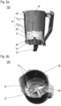
- FIGS 1a, 1b and 1c show a jar 100 according to an exemplary embodiment of the present invention in different states.
- the jar 100 comprises a tool holder 10, a cooler element 20 and a wall component 30.
- the cooler element 20 is ring-shaped, and a tool being a rotatable blade assembly 40 is held by the tool holder 10.
- the blade assembly 40 is detachably mounted to the tool holder 10.
- the tool holder 10 may advantageously be configured to selectively hold one of various tools, which may comprise different blade assemblies and/or beaters (not shown).
- the cooler element 20 may advantageously comprise at least one double walled region encasing a solution which freezes in a fridge and/or a household freezer.
- the cooler element 20 may comprise a phase-change material.
- Figure 1a shows the tool holder 10, the cooler element 20 and the wall component 30 in an uncombined, i.e., disassembled state
- Figure 1b depicts a situation in which the cooler element 20 is detachably fixed to the tool holder 10.
- the tool holder 10 and the cooler element 20 together form a bottom part 110 of the jar 100.
- the cooler element 20 is detachably fixable to the tool holder 10 by means of a screw fitting, or by means of a form-fit connection such as a snap-lock and/or a bayonet joint (not visible in the figures).
- a seal ring 11 is configured to seal a contact region of the tool holder 10 and the cooler element 20 and/or a contact region of the tool holder 10 and the wall component 30.
- the wall component 30 is detachably fixable (such as by means of a screw fitting, or by means of a form-fit connection such as a snap-lock and/or a bayonet joint) to the bottom part 110, in particular to the tool holder 10 and/or to the cooler element 20 thereof.
- Figure 1c shows the jar 100 in such an assembled state, in which the tool holder 10, the cooler element 20 and the wall component 30 are combined.
- the cooler element 20 and the tool holder 10 are inserted in a bottom portion 31 of the wall component 30.
- the wall component 30 surrounds the ring-shaped cooler element 20.
- a pivotable handle 12 permits a user to easily grip and operate the bottom part 110 when fixing the wall component 30 to it, which fixing may comprise a linear and/or a rotational movement of the tool holder 10 relative to the wall component 30.
- the handle 12 may be pivoted so as to also be plunged in the bottom portion 31 of the wall component 30.
- the tool holder 10, the cooler element 20 and the wall component 30 together define a food reception space R of the jar 100, as is better shown in Figures 2a and 2b each providing a view in the jar 100 and, thereby, in the food reception space R.
- FIG 2a a sectional view of the jar 100 formed by the tool holder 10, the cooler element 20 and the wall component 30 in their combined state is presented, and Figure 2b shows the jar 100 with its food reception space R from above (with respect to an orientation designated for processing food in the jar).
- a bottom of the food reception space R is at least partially defined by the tool holder 10, and both the wall component 30 and the cooler element 20 (in particular, a surface S thereof) further delimit the food reception space R by together forming a lateral jacket of the jar.
- the jar 100 has a profile comprising protrusions P extending over both the wall component 30 and the cooler element 20.
- the protrusions P each have a section P 30 in which they are formed by the wall component 30, and a section P 20 in which they are formed by the cooler element 20.
- the protrusions P may serve to obstruct food when this is being processed by the rotating blade assembly 40, and to redirect it towards the blade assembly 40.
- these sections P 20 may provide for a particularly good capacity of holding cold.
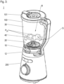
- FIG 3 schematically illustrates the setup of a blender 1 according to an exemplary embodiment of the present invention.
- the blender 1 comprises a jar 100 and a base 200 containing an electric motor (not visible in Figure 3 ).
- an electric motor not visible in Figure 3
- the jar 100 and the cooler element 20 are depicted as partially transparent.
- a representation of the wall component's surface delimiting the food reception space R is omitted.
- the jar 100 is shown as being set in an operation position after the pivotable handle 12 has been swivelled so as to unblock a bottom surface of the jar 100.
- the electric motor is coupled with the blade assembly 40.
- the cooler element 20 may advantageously be combined, with the tool holder 10 and the wall component 30, after having been stored in a fridge or a household freezer, such as for several hours. Due to the cooler element 20 delimiting, with its surface S, the food reception space R of the assembled jar 100, food being processed in the jar 100 is then cooled by the cooler element 20. Thereby, cold drinks, in particular smoothies can be easily and conveniently made even in a domestic environment.
- a jar 100 for or of a blender 1 comprises a tool holder 10, a wall component 30 and a cooler element 20 which are detachably combinable such that, in a combined state, they define a food reception space R designated to receive food to be processed by the blender 1. Therein the cooler element 20 at least partially delimits the food reception space R.
- a (stationary) blender 1 with such jar 100 and a base 200, the base defining an operation position of the jar 100 and comprising an electric motor.
Abstract
Description
- The present invention concerns a jar comprising a tool holder, a wall component and a cooler element. The invention further concerns a (stationary) blender with a base and such jar.
- Conventional blenders are devised for domestic use and typically comprise a jar and a base. The jar usually is composed of a knife holder configured to hold a blade assembly and forming a bottom of the jar, and a wall component detachably combinable to the knife holder so as to form the jar. The base comprises an electric motor and defines an operation position for the jar. In this position of the jar, the blade assembly held by the knife holder is coupled to the electric motor which thus is adapted to rotate the blade assembly. Thereby, food may be chopped, mixed and/or liquefied.
- It is an object of the present invention to provide a jar and a blender, which are improved so as to facilitate a simple and convenient preparation of a broadened class of foods.
- The object is achieved by a jar according to
claim 1, and by a blender according to claim 8. Advantageous embodiments are disclosed in the dependent claims, the description and the figures. - A jar according to the present invention belongs to a blender or is configured to form part of a blender. The jar comprises a tool holder, a wall component and a cooler element, which are detachably combinable. In a combined state (i.e., when the jar has been assembled), they together define a food reception space of the jar, the food reception space designated to receive food to be processed by the blender (in particular, by a tool the tool holder may hold). Therein, the cooler element (i.e., a surface thereof) at least partially delimits the food reception space.
- A blender according to the present invention comprises a jar according to an embodiment of the present invention, and a base defining an operation position of the jar and comprising an electric motor. When the jar is positioned at the operation position, the electric motor is coupled with a tool when this is (preferably detachably) fixed to the tool holder.
- The cooler element is designated to be put - prior to its utilisation - in a cooling environment such as a household refrigerator or a domestic freezer, and thus may be cooled therefrom. As it delimits, after being combined, the food reception space, when food is present in the food reception space, the food may contact the cooler element. The present invention thus facilitates that, if the cooler element has recently been taken out of the cooling environment before assembling and using the jar (along with a base of the blender), the temperature of the food being processed may be lowered due to its contact with the cooler element. Therefore, the present invention provides a convenient and easily employable passive cooling means for preparing, in a domestic environment, cool stirred and/or ground food such as frosty smoothies.
- The cooler element may comprise one or more double-walled regions including a chamber which may contain a solution (such as salt water and/or urea) freezing at a temperature below 0°C. In particular, the cooler element may preferably contain a latent heat accumulator which can comprise a phase change material.
- According to preferred embodiments, the cooler element is ring-shaped.
- The tool holder, the wall component and/or the cooler element may comprise means for a frictional connection (e.g., a (respective) screw thread) and/or means for a form-fit connection (such as at least one snap-lock means and/or at least one bayonet joint), which respectively may provide for detachably combining said components. In particular, the wall component, the cooler element and/or the tool holder may respectively comprise at least one fixation element (such as a pin, a screw thread and/or a cavity) configured to engage with at least one fixation element (such as a pin, a screw thread and/or a cavity) of a respective other one of the wall component, the cooler element and/or the tool holder.
- Preferably, the cooler element at least partially delimits the food reception space in a bottom region thereof. For instance, it may at least partially delimit a lowest third or even a lowest fourth of the food reception space; in this document, the terms "bottom" and "low" and its derivatives each relate to an orientation designated for processing food in the assembled jar. In particular, a cooler element's surface delimiting the food reception space may advantageously at least partially abut a tool holder's surface facing (and also delimiting) the food reception space.
- In particular, the cooler element may preferably be detachably fixable to the tool holder so as to build a bottom part of the jar, and the wall component may then be detachably fixable to the bottom part, in particular to the tool holder and/or to the cooler element thereof. Therein, the cooler element may be detachably fixable to the tool holder by means of at least one screw connection and/or at least one form-fit connection, such as at least one snap-lock means and/or at least one bayonet joint. Additionally or alternatively, the wall component may be detachably fixable to the bottom part by means of a screw connection or a form-fit connection, such as at least one snap-lock means and/or at least one bayonet joint.
- Such embodiments facilitate a particularly comfortable and quick assembly of the jar.
- The wall component may form a pipe with a first end and a second end, the first end surrounding a feed opening of the jar (i.e., through which in use of the jar food to be processed may be filled into the food reception space), the second end surrounding an opening configured to receive the tool holder and/or the cooler element when the wall component is combined thereto. The jar may also be shaped so that its horizontal section is not a circle or a circle-like shape but can also be a polygonal shape, for instance a hexagonal.
- According to advantageous embodiments, in a combined state of the tool holder, the wall component and the cooler element, the cooler element is at least partially (in particular, entirely) surrounded by the wall component. In particular, the cooler element may be inserted in said opening at said second end of the wall component.
- According to advantageous embodiments, the tool holder and the wall component are detachably combinable for use selectively with or without the cooler component. That is, the tool holder and the wall component are configured to be combined to each other even when omitting the cooler element, thus forming a components-reduced jar with a sealed further food reception space (which is enlarged as compared to the food reception space formed using the cooler element). Such embodiments facilitate utilisation of the blender (for processing food not to be cooled) also without the cooler element, for example while the cooler element is deposited in a cooling environment (such as a refrigerator or a freezer).
- A surface (of the jar) which at least partially delimits the food reception space may preferably have a profile comprising one or more protrusions (i.e. flow breaking elements). In use of the blender, such a profile may serve to obstruct food being processed by a rotating tool, and to redirect it towards the tool. Preferably, at least one of such protrusions may extend over both a surface of the wall component and a cooler element's surface delimiting the food reception space.
- In the following, preferred embodiments of the present invention are explained with respect to the accompanying drawings. As is to be understood, the various elements and components are depicted as examples only, may be facultative and/or combined in a manner different than that depicted. Reference signs for related elements are used comprehensively and not defined again for each figure.
- Shown is schematically in
- Fig. 1a:
- an exemplary embodiment of a jar according to the present invention in a disassembled state;
- Fig. 1b:
- the jar of
Figure 1a in a partially assembled state; - Fig. 1c
- the jar of
Figures 1a and 1b in an assembled state; - Fig. 2a:
- a sectional view of the jar of
Figures 1a to 1c ; - Fig. 2b:
- an view from above into the food reception space of the jar; and
- Fig. 3:
- the setup of a blender according to an exemplary embodiment of the present invention.
-
Figures 1a, 1b and 1c show ajar 100 according to an exemplary embodiment of the present invention in different states. Thejar 100 comprises atool holder 10, acooler element 20 and awall component 30. In the present case, thecooler element 20 is ring-shaped, and a tool being arotatable blade assembly 40 is held by thetool holder 10. Preferably, theblade assembly 40 is detachably mounted to thetool holder 10. In particular, thetool holder 10 may advantageously be configured to selectively hold one of various tools, which may comprise different blade assemblies and/or beaters (not shown). - The
cooler element 20 may advantageously comprise at least one double walled region encasing a solution which freezes in a fridge and/or a household freezer. In particular, thecooler element 20 may comprise a phase-change material. -
Figure 1a shows thetool holder 10, thecooler element 20 and thewall component 30 in an uncombined, i.e., disassembled state, whereasFigure 1b depicts a situation in which thecooler element 20 is detachably fixed to thetool holder 10. Such combined, thetool holder 10 and thecooler element 20 together form abottom part 110 of thejar 100. Preferably, thecooler element 20 is detachably fixable to thetool holder 10 by means of a screw fitting, or by means of a form-fit connection such as a snap-lock and/or a bayonet joint (not visible in the figures). In the example shown inFigures 1a to 1c , a seal ring 11 is configured to seal a contact region of thetool holder 10 and thecooler element 20 and/or a contact region of thetool holder 10 and thewall component 30. - For further assembling the
jar 100, thewall component 30 is detachably fixable (such as by means of a screw fitting, or by means of a form-fit connection such as a snap-lock and/or a bayonet joint) to thebottom part 110, in particular to thetool holder 10 and/or to thecooler element 20 thereof. -
Figure 1c shows thejar 100 in such an assembled state, in which thetool holder 10, thecooler element 20 and thewall component 30 are combined. Therein, in the embodiment shown, thecooler element 20 and thetool holder 10 are inserted in abottom portion 31 of thewall component 30. In particular, thewall component 30 surrounds the ring-shapedcooler element 20. A pivotable handle 12 permits a user to easily grip and operate thebottom part 110 when fixing thewall component 30 to it, which fixing may comprise a linear and/or a rotational movement of thetool holder 10 relative to thewall component 30. - Thereafter, the
handle 12 may be pivoted so as to also be plunged in thebottom portion 31 of thewall component 30. - In the combined state, the
tool holder 10, thecooler element 20 and thewall component 30 together define a food reception space R of thejar 100, as is better shown inFigures 2a and 2b each providing a view in thejar 100 and, thereby, in the food reception space R. - In
Figure 2a , a sectional view of thejar 100 formed by thetool holder 10, thecooler element 20 and thewall component 30 in their combined state is presented, andFigure 2b shows thejar 100 with its food reception space R from above (with respect to an orientation designated for processing food in the jar). As can be taken from bothFigure 2a and Figure 2b , a bottom of the food reception space R is at least partially defined by thetool holder 10, and both thewall component 30 and the cooler element 20 (in particular, a surface S thereof) further delimit the food reception space R by together forming a lateral jacket of the jar. - As can be further taken from
Figures 2a and 2b , at a surface delimiting the food reception space R, thejar 100 has a profile comprising protrusions P extending over both thewall component 30 and thecooler element 20. Indeed, the protrusions P each have a section P30 in which they are formed by thewall component 30, and a section P20 in which they are formed by thecooler element 20. The protrusions P may serve to obstruct food when this is being processed by therotating blade assembly 40, and to redirect it towards theblade assembly 40. Moreover, as thecooler element 20 is thickened in its sections P20 of the protrusions P, these sections P20 may provide for a particularly good capacity of holding cold. -
Figure 3 schematically illustrates the setup of ablender 1 according to an exemplary embodiment of the present invention. Theblender 1 comprises ajar 100 and a base 200 containing an electric motor (not visible inFigure 3 ). To indicate thecooler element 20 and theblade assembly 40 thereof, inFigure 3 , thejar 100 and thecooler element 20 are depicted as partially transparent. However, to improve clarity of the figure, a representation of the wall component's surface delimiting the food reception space R (with the sections P30 of the protrusions P shown inFigure 2a, 2b ) is omitted. - In
Figure 3 , thejar 100 is shown as being set in an operation position after thepivotable handle 12 has been swivelled so as to unblock a bottom surface of thejar 100. In the operation position, the electric motor is coupled with theblade assembly 40. - In use, the
cooler element 20 may advantageously be combined, with thetool holder 10 and thewall component 30, after having been stored in a fridge or a household freezer, such as for several hours. Due to thecooler element 20 delimiting, with its surface S, the food reception space R of the assembledjar 100, food being processed in thejar 100 is then cooled by thecooler element 20. Thereby, cold drinks, in particular smoothies can be easily and conveniently made even in a domestic environment. - Disclosed is a
jar 100 for or of ablender 1. The jar comprises atool holder 10, awall component 30 and acooler element 20 which are detachably combinable such that, in a combined state, they define a food reception space R designated to receive food to be processed by theblender 1. Therein thecooler element 20 at least partially delimits the food reception space R. - Further disclosed is a (stationary)
blender 1 withsuch jar 100 and abase 200, the base defining an operation position of thejar 100 and comprising an electric motor. -
- 1
- blender
- 10
- tool holder
- 11
- seal ring
- 12
- handle
- 20
- cooler element
- 30
- wall component
- 31
- bottom part
- 40
- blade assembly
- 100
- jar
- 110
- bottom part
- 200
- base
- P
- protrusion
- P20, P30
- section of protrusion P
- R
- food reception space
- S
- surface of cooler element
Claims (8)
- Jar (100) for or of a blender (1), the jar comprising a tool holder (10), a wall component (30) and a cooler element (20) which are detachably combinable such that, in a combined state, they define a food reception space (R) designated to receive food to be processed by the blender (1), wherein the cooler element (20) at least partially delimits the food reception space (R).
- Jar according to claim 1, wherein the cooler element (20) is detachably fixable to the tool holder (10) so as to build a bottom part (110) of the jar, and the wall component (30) is detachably fixable to the bottom part (110).
- Jar according to one of claims 1 or 2, wherein the cooler element (20) is detachably fixable to the tool holder (10) by means of a form-fit connection, in particular by means of at least one snap-lock means and/or at least one bayonet joint.
- Jar according to one of the preceding claims, wherein the cooler element (20) is ring-shaped.
- Jar according to one of the preceding claims, wherein in said combined state, the cooler element (20) is at least partially surrounded by the wall component (30).
- Jar according to one of the preceding claims, wherein the tool holder (10) and the wall component (30) are combinable for use selectively with or without the cooler component (20).
- Jar according to one of the preceding claims, wherein at a surface delimiting the food reception space, the jar has a profile comprising one or more protrusions (P) extending over both the wall component (30) and the cooler element (20).
- Blender (1) with a jar (100) according to one of the preceding claims, and with a base (200) comprising an electric motor and defining an operation position for the jar, in which operation position the electric motor is configured to be coupled with a tool (40) fixed to the tool holder (10).
Priority Applications (1)
| Application Number | Priority Date | Filing Date | Title |
|---|---|---|---|
| EP21208481.8A EP4179934A1 (en) | 2021-11-16 | 2021-11-16 | Jar with a tool holder, a wall component and a cooler element, and blender with such jar |
Applications Claiming Priority (1)
| Application Number | Priority Date | Filing Date | Title |
|---|---|---|---|
| EP21208481.8A EP4179934A1 (en) | 2021-11-16 | 2021-11-16 | Jar with a tool holder, a wall component and a cooler element, and blender with such jar |
Publications (1)
| Publication Number | Publication Date |
|---|---|
| EP4179934A1 true EP4179934A1 (en) | 2023-05-17 |
Family
ID=78676333
Family Applications (1)
| Application Number | Title | Priority Date | Filing Date |
|---|---|---|---|
| EP21208481.8A Pending EP4179934A1 (en) | 2021-11-16 | 2021-11-16 | Jar with a tool holder, a wall component and a cooler element, and blender with such jar |
Country Status (1)
| Country | Link |
|---|---|
| EP (1) | EP4179934A1 (en) |
Citations (5)
| Publication number | Priority date | Publication date | Assignee | Title |
|---|---|---|---|---|
| US4205535A (en) * | 1977-09-26 | 1980-06-03 | M & F Engineering Ag | Household soft-ice-cream machine |
| US4696166A (en) * | 1985-06-26 | 1987-09-29 | U.S. Philips Corporation | Ice-cream maker |
| DE3806508A1 (en) * | 1988-03-01 | 1989-09-14 | Norbert Flammann | Ice-cream maker |
| EP3369353A1 (en) * | 2017-03-01 | 2018-09-05 | Taurus Research and Development S.L.U. | Food processing apparatus for preparing ice cream |
| EP3692799A1 (en) * | 2019-02-06 | 2020-08-12 | SMEG S.p.A. | Ice cream maker fitting for a stand mixer, ice cream maker kit for a stand mixer and stand mixer |
-
2021
- 2021-11-16 EP EP21208481.8A patent/EP4179934A1/en active Pending
Patent Citations (5)
| Publication number | Priority date | Publication date | Assignee | Title |
|---|---|---|---|---|
| US4205535A (en) * | 1977-09-26 | 1980-06-03 | M & F Engineering Ag | Household soft-ice-cream machine |
| US4696166A (en) * | 1985-06-26 | 1987-09-29 | U.S. Philips Corporation | Ice-cream maker |
| DE3806508A1 (en) * | 1988-03-01 | 1989-09-14 | Norbert Flammann | Ice-cream maker |
| EP3369353A1 (en) * | 2017-03-01 | 2018-09-05 | Taurus Research and Development S.L.U. | Food processing apparatus for preparing ice cream |
| EP3692799A1 (en) * | 2019-02-06 | 2020-08-12 | SMEG S.p.A. | Ice cream maker fitting for a stand mixer, ice cream maker kit for a stand mixer and stand mixer |
Similar Documents
| Publication | Publication Date | Title |
|---|---|---|
| EP3073839B1 (en) | Improved base driven appliance and attachments | |
| US11439157B2 (en) | Ice cream maker fitting for a stand mixer, ice cream maker kit for a stand mixer and stand mixer | |
| CN110680211A (en) | Preparation container with cooling device | |
| US11596162B2 (en) | Ice cream maker fitting for a stand mixer, ice cream maker kit for a stand mixer and stand mixer | |
| US8388217B2 (en) | Cooling stick for a blender and method of using same | |
| CN205358065U (en) | A mandrel that is used for gear of taking of food processor | |
| US5360176A (en) | Blender | |
| US20060171248A1 (en) | Blender | |
| EP2409576B1 (en) | Home and professional ice cream product making machine | |
| US4887909A (en) | Blender with thermally insulated container | |
| US20140130538A1 (en) | Wooden ice cream maker | |
| US7412845B2 (en) | Ice cream maker including nestable canister assembly | |
| US20060156754A1 (en) | Apparatus for producing and dispensing a chilled or partially frozen beverage | |
| US4551026A (en) | Household appliance for making ice cream | |
| US20080257173A1 (en) | Dessert and ice cream making apparatus | |
| US6332333B1 (en) | Ice-cream freezer | |
| EP4179934A1 (en) | Jar with a tool holder, a wall component and a cooler element, and blender with such jar | |
| EP3250046A1 (en) | Apparatus for preparing ice cream and like frozen products | |
| KR950008382B1 (en) | Refregerator using stiring cycle | |
| JPH0131030Y2 (en) | ||
| MX2008014951A (en) | Method for the operation of a container suitable for freezing the content thereof, and ice cream maker. | |
| US20050105386A1 (en) | Mixing paddle for cooling a mixture | |
| CN108703608A (en) | It is a kind of to be quickly cooled down or heat liquid or the multifunctional cup as cold storage container | |
| US20220090839A1 (en) | Refrigeration and Freezer Pot | |
| CN113712451B (en) | Chef machine |
Legal Events
| Date | Code | Title | Description |
|---|---|---|---|
| PUAI | Public reference made under article 153(3) epc to a published international application that has entered the european phase |
Free format text: ORIGINAL CODE: 0009012 |
|
| STAA | Information on the status of an ep patent application or granted ep patent |
Free format text: STATUS: THE APPLICATION HAS BEEN PUBLISHED |
|
| AK | Designated contracting states |
Kind code of ref document: A1 Designated state(s): AL AT BE BG CH CY CZ DE DK EE ES FI FR GB GR HR HU IE IS IT LI LT LU LV MC MK MT NL NO PL PT RO RS SE SI SK SM TR |
|
| STAA | Information on the status of an ep patent application or granted ep patent |
Free format text: STATUS: REQUEST FOR EXAMINATION WAS MADE |
|
| 17P | Request for examination filed |
Effective date: 20231117 |
|
| RBV | Designated contracting states (corrected) |
Designated state(s): AL AT BE BG CH CY CZ DE DK EE ES FI FR GB GR HR HU IE IS IT LI LT LU LV MC MK MT NL NO PL PT RO RS SE SI SK SM TR |