EP4178166A2 - Adapter unit and method for coupling an evaluation unit to a data bus, and system and vehicle with corresponding adapter unit - Google Patents
Adapter unit and method for coupling an evaluation unit to a data bus, and system and vehicle with corresponding adapter unit Download PDFInfo
- Publication number
- EP4178166A2 EP4178166A2 EP22204237.6A EP22204237A EP4178166A2 EP 4178166 A2 EP4178166 A2 EP 4178166A2 EP 22204237 A EP22204237 A EP 22204237A EP 4178166 A2 EP4178166 A2 EP 4178166A2
- Authority
- EP
- European Patent Office
- Prior art keywords
- bus
- data
- unit
- signal
- adapter unit
- Prior art date
- Legal status (The legal status is an assumption and is not a legal conclusion. Google has not performed a legal analysis and makes no representation as to the accuracy of the status listed.)
- Pending
Links
Images
Classifications
-
- H—ELECTRICITY
- H04—ELECTRIC COMMUNICATION TECHNIQUE
- H04L—TRANSMISSION OF DIGITAL INFORMATION, e.g. TELEGRAPHIC COMMUNICATION
- H04L12/00—Data switching networks
- H04L12/28—Data switching networks characterised by path configuration, e.g. LAN [Local Area Networks] or WAN [Wide Area Networks]
- H04L12/40—Bus networks
- H04L12/40006—Architecture of a communication node
- H04L12/40032—Details regarding a bus interface enhancer
-
- H—ELECTRICITY
- H04—ELECTRIC COMMUNICATION TECHNIQUE
- H04L—TRANSMISSION OF DIGITAL INFORMATION, e.g. TELEGRAPHIC COMMUNICATION
- H04L12/00—Data switching networks
- H04L12/28—Data switching networks characterised by path configuration, e.g. LAN [Local Area Networks] or WAN [Wide Area Networks]
- H04L12/40—Bus networks
- H04L2012/40267—Bus for use in transportation systems
Definitions
- the present disclosure relates to an adapter unit for coupling an evaluation unit to a data bus, preferably a data bus in a vehicle, particularly preferably a data bus in a rail vehicle.
- the present disclosure also relates to a system and a vehicle with such an adapter unit and a corresponding method.
- Data buses are used to exchange data between several bus participants.
- the data is encoded in bus signals and the bus signals are transmitted via a bus medium (copper cable, fiber optic cable, etc.).
- the bus medium is usually accessed using TDMA - Time Division Multiple Access - which is why only one participant is allowed to send data to the data bus at a time. Otherwise, the bus signals of the various sending participants overlap and the data transmissions interfere with each other.
- a master assigns transmission authorization to the participants. This can be done by enabling individual bus accesses, by allocating fixed time slots for the participants, by allocating transmission channels and/or the like.
- nodes listen into the bus and start sending when no bus activity is detected. As soon as a collision of data transmissions from several participants is possible, mechanisms for collision detection are common. If a collision is detected, a suitable response is made to the detected collision, for example the transmission process is aborted and restarted at a later point in time.
- bus signals are usually decoupled from the data bus and fed to the participant.
- inductive or capacitive decoupling is common in practice. Nevertheless, this eavesdropping participation is not unproblematic. Because the lowest possible reaction of a participant to a data bus usually also means the lowest possible coupling inductance or coupling capacitance, which means that manufacturing tolerances, different installation situations and/or other framework conditions can have a significant impact on the quality of bus signals that are decoupled and their usability.
- the U.S. 2009/0279645 A1 discloses a device that can be clipped onto lines of a data bus (such as those of a CAN-Controller Area Network bus).
- the electrical bus signals transmitted via the bus lines couple capacitively to electrodes of the device and are reconstructed in a circuit.
- the bus signals reconstructed in this way are fed to a reading bus subscriber.
- a disadvantage of this device is that the mostly twisted bus lines have to be untwisted to attach the device, which means that the channel properties of the bus line are changed locally.
- the capacitive coupling between the bus line and electrodes depends on many factors, such as the thickness of the insulation of the bus lines, the type and quality of attachment of the device to the bus line, the distance of the device from the transmitting participant, the proximity to be shielded or derived surfaces, etc. As a result, the transmission properties vary considerably from installation to installation.
- the object of the present disclosure is to provide an adapter unit, a system, a vehicle and a method with which an evaluation unit can be coupled to a data bus as flexibly and universally as possible, with the least possible influence on the channel properties of the bus and one of various installation situations independent behavior is desirable.
- this object is achieved by the features of claim 13, with regard to a vehicle by the features of claim 14 and with regard to a method by the features of claim 15.
- the adapter unit of the present disclosure includes a coupling unit with a primary-side conductor structure and a secondary-side conductor structure.
- the adapter unit is connected to the data bus via a bus input.
- This bus input is in turn connected to the conductor structure on the primary side.
- the primary-side conductor structure and the secondary-side conductor structure are arranged and formed in such a way that a capacitive coupling occurs between at least a part of the primary-side conductor structure and at least a part of the secondary-side conductor structure.
- bus signals can couple over to the secondary-side conductor structure in a defined manner via a coupling capacitance formed in this way. Since this coupling unit has the same coupling properties in all installation situations, the operation of the adapter unit is essentially independent of the installation situation.
- An overcoupled bus signal which originates from the bus signal input into the bus input and is capacitively overcoupled onto the secondary-side conductor structure, is input into a signal conditioning unit.
- the overcoupled bus signal is processed there and a processed bus signal is thereby generated.
- the processed bus signal is input into a decoding unit, which decodes bus data encoded in the processed bus signal and generates and outputs decoded bus data therefrom.
- the decoded bus data are entered into an interface module that can output the decoded bus data to the evaluation unit.
- bus data transmitted via the data bus can be decoupled from the data bus in a deterministic manner and fed to an evaluation unit in a wide variety of ways.
- the bus data output to the evaluation unit can be used extremely flexibly and are largely independent of the data bus used. This also enables an interface change, which in turn enables particularly universal use.
- such an adapter unit offers transparent and essentially reaction-free access to the data bus. Due to the universal design, the adapter unit can be retrofitted into existing data buses, which makes the adapter unit even more universally applicable.
- An “evaluation unit” that can be connected to the adapter unit can be formed by a wide variety of reading terminals.
- Such an evaluation unit can evaluate the received bus data in a wide variety of ways, with “evaluation” being understood in the broadest sense.
- This “evaluation” can include, for example, storing received bus data in the sense of a data logger.
- the evaluation unit can carry out permanent monitoring of the data bus and the communication transmitted there.
- the bus data and the communication behavior of the bus can be interpreted and its participants can be monitored.
- This short, non-exhaustive and, in particular, non-limiting listing of conceivable evaluation units shows how universally the adapter unit can be used.
- the "data bus” can be formed by a wide variety of buses. It is important that bus data can be transmitted via the data bus and made accessible to an evaluation unit.
- bus media can be used are used that enable a wide variety of transmissions, for example electrical, optical, wireless, etc.
- access to the bus can be implemented in a wide variety of ways. Examples include TDMA—Time Division Multiple Access—FDMA—Frequency Division Multiple Access—and CDMA—Code Division Multiple Access.
- the bus signals can be modulated in various ways, for example using PSK—phase shift keying—, FSK—frequency shift keying—or ASK—amplitude shift keying—to name just a few conceivable types of modulation.
- PSK phase shift keying
- FSK frequency shift keying
- ASK amplitude shift keying
- the “bus input” should also be configured. This can include, for example, an adaptation to the bus medium used in each case. For example, if the data bus uses a copper cable as the bus medium, the bus input should be designed to connect to this copper cable. If the data bus uses an optical waveguide, for example a glass fiber, the bus input should be designed for connection to this optical waveguide. Accordingly, it is advisable if the bus input has an adjusted number of poles. For example, if the data bus uses two twisted-pair wires to transmit the bus signals, the bus input should have two pins.
- Bus signals can in principle be all signals that are transmitted via a data bus and in which bus data can be encoded. Depending on the design of the bus medium, the bus signals may also differ. In the case of an optical bus medium, for example, the bus signal can be a laser beam whose intensity is modulated. With a copper cable as the bus medium, the bus signal can be an electrical signal. Without loss of generality, the following assumed that the bus signal is an electrical signal. The electrical signal can be transmitted directly on the bus. However, it is also conceivable that optical signals, electromagnetic signals or the like are used for the transmission of the bus data via the bus. Since such signals are usually converted into electrical signals for further processing, the assumption of a bus signal as an electrical signal does not represent a restriction of generality.
- the bus signals can be coded in different ways, have different levels or use different frequencies, to give just a few examples to name.
- the "primary-side conductor structure” and the “secondary-side conductor structure” can also be realized in various ways. It is important that a coupling capacitance forms between at least parts of these conductor structures, i.e. an area in which an electrical signal can couple from the primary-side conductor structure to the secondary-side conductor structure by means of an electrical field. This prerequisite can be realized in various ways known from practice.
- the entire conductor structure on the primary side and the entire conductor structure on the secondary side can form this coupling capacitance.
- the remaining parts serving, for example, as feed lines for the sections of the coupling capacitance.
- the at least one part of the primary-side conductor structure and the at least one part of the secondary-side conductor structure can extend relatively arbitrarily.
- the parts are formed by straight conductor sections.
- the parts are curved, for example as an arc of a circle, as a section of an ellipse or as some other curved curve. In this case, it may be advisable for the conductor structure on the primary side and the conductor structure on the secondary side to have no pronounced corners, in order to reduce or even avoid electromagnetic radiation at higher frequencies of the bus signal, for example.
- the primary-side conductor structure and/or the secondary-side conductor structure can each be formed by a single conductor.
- the conductor structure on the primary side and/or the conductor structure on the secondary side comprises a plurality of conductors connected in parallel, of which at least part of the conductor structure can contribute to the coupling capacitance.
- the bus medium can be spanned by two conductors, via which the bus signal is impressed differentially.
- the conductor structure on the primary side and/or the conductor structure on the secondary side can also be constructed in multiple parts.
- the conductor structure on the primary side can have a first conductor section on the primary side and a second conductor section on the primary side. The first bus conductor can then be connected to the first conductor section on the primary side and the second bus conductor can be connected to the second conductor section on the primary side.
- the secondary-side conductor structure would also comprise a first secondary-side conductor section and a second secondary-side conductor section, with the first primary-side conductor section and the first secondary-side conductor section forming a first coupling capacitance and the second primary-side conductor section and the second secondary-side conductor section forming a second coupling capacitance.
- the signal on the first bus conductor can couple onto the first conductor section on the secondary side and the signal on the second bus conductor can couple over onto the second conductor section on the secondary side.
- the signals at the two conductor sections on the secondary side can then be tapped and amplified, for example, with a differential amplifier.
- the "interface module” is designed to output decoded bus data to the evaluation unit.
- the decoded bus data should usually be output via an appropriately designed interface.
- the adapter unit can therefore have a corresponding output interface.
- the interface module then outputs the decoded data—suitably encoded—to the evaluation unit via the output interface.
- the output interface can be designed so that it can be separated. A plug connection can be provided for this purpose.
- the adapter unit can be implemented in many different ways. An implementation by pure hardware is just as conceivable as an implementation in pure software. However, preferably the adapter unit is implemented by a combination of software and hardware.
- a microprocessor, a microcontroller and/or another programmable logic module for example FPGA—Field Programmable Gate Array—, CPLD—Complex Programmable Logic Device—, ASIC—Application Programmable Integrated Circuit—, etc.
- FPGA Field Programmable Gate Array
- CPLD Complex Programmable Logic Device
- ASIC Application Programmable Integrated Circuit—, etc.
- the at least one part of the conductor structure on the primary side and the at least one part of the conductor structure on the secondary side, which together form the coupling capacitance are formed by parallel conductors.
- These parallel conductors can be formed by parallel straight sections.
- curves that run at approximately the same distance from one another can also be regarded as "parallel conductors" in this sense.
- arcs of circles with the same center and different radii can form parallel conductors.
- Parallel conductors offer the advantage that a coupling capacitance with a capacitance value that can be easily controlled and calculated can arise.
- the at least one part of the primary-side conductor structure and the at least one part of the secondary-side conductor structure, which together form the coupling capacitance are formed by conductors on a circuit board, with the conductors preferably being arranged on different levels of the circuit board.
- Conductors on a circuit board offer the advantage that their relative position is clearly defined at least in one direction through the circuit board. This can simplify the production of the coupling capacitance. If the conductors are arranged on different levels of the circuit board, there is also the advantage that the conductors can better form a coupling capacitance. Because the conductors on a circuit board are usually wider than they are thick, so that electrical fields can form better between the conductors. If the circuit board has conductors on more than two levels, the field distribution can also be better controlled and, depending on the arrangement of the conductors, shielding against external interference can be achieved.
- the coupling capacitance has a capacitance value that is so small that a bus signal transmitted via the bus remains essentially unaffected by the coupling capacitance.
- the specific capacitance value usually depends on the data bus used, the length of the data bus, the specific transmission technology used and many other factors. In a further development, the capacitance value is in the picofarad range.
- the coupling capacitance has a capacitance value between 0.1 picofarad and 10 picofarad, preferably between 1 picofarad and 5 picofarad. These values provide good results with an MVB, for example, and can achieve sufficiently good overcoupling of the bus signal into the conductor structure on the secondary side.
- the signal processing unit has a filter, an amplifier and/or an analog/digital converter.
- the filter is preferably a bandpass filter.
- the filter can be used to reduce noise coupled into the bus signal.
- a bandpass filter can isolate the expected spectrum of the bus signal.
- An amplifier can amplify the injected bus signal, which should be at a relatively low level.
- the amplifier can also be a differential amplifier which amplifies a difference between two input signals, for example between the aforementioned first secondary-side conductor section and the second secondary-side conductor section.
- a filter can be placed before the amplifier and/or after the amplifier.
- An analog-to-digital converter can generate a digital signal from the analog bus signal, which can then be processed digitally in the decoding unit.
- the overcoupled bus signal is input to the amplifier, the amplifier generates an amplified bus signal by amplifying the overcoupled bus signal, which is input to the analog-to-digital converter, and the analog-to-digital converter generates a digitized one by digitizing the amplified bus signal Bus signal, where the digitized bus signal is input to the amplifier as positive feedback.
- This refinement offers the advantage that the processing of the overcoupled bus signal can be significantly improved. Because of this special interconnection, the conditions of a transmission and possible disturbances can be recognized better. Certain information is lost as a result of capacitive decoupling of the bus signal, for example the respective voltage level, an idle level, an exact voltage difference and/or other transmission conditions.
- the decoding unit is adapted to the coding of the bus signal of the bus and preferably carries out Manchester decoding, frame recognition, error recognition and/or error correction.
- Frame recognition can be of particular interest in the case of data buses in which the bus data is transmitted in data frames—so-called frames. If a frame is detected, this favors the decoding of the bus data.
- Error detection can detect incorrectly transmitted bus data. Since the adapter unit usually only listens into the bus communication and does not use a transmission channel, the source of the incorrectly transmitted bus data cannot be informed that data has been incorrectly transmitted. Nonetheless, this information can be useful.
- incorrectly transmitted bus data may also arrive at the sink with errors and be requested again, incorrectly received bus data may provide information for the connected evaluation unit, for example with regard to recognizing a generally faulty bus communication, etc.
- the adapter unit comprises a timer and a time stamp, the timer supplying a time reference and the time stamp being designed to provide decoded bus data with a time stamp using the time reference.
- a timer allows a time reference to be made hold without the need for a permanent communication link to an external timer.
- An external timer can still be reached for synchronization of the timer, with the help of which the time reference of the timer can be set.
- Corresponding external clocks could be, for example, a time transmitter based on DCF77, an NTP—Network Time Protocol server or the like.
- the time stamp allows decoded bus data to be placed in a time context. This can be helpful, for example, in an error analysis of the bus data by the evaluation unit.
- the time stamp that the time stamper generates is based on the clock's time reference and would be appended to the decoded bus data in a record. This data record can then be stored and/or output to the evaluation unit via the interface module.
- the adapter unit has a memory which is designed to store decoded bus data and any associated time stamps and preferably to keep them available for later output via the interface module to the evaluation unit, the memory preferably being a FIFO (First In First Out) and / or is designed as a ring memory.
- a memory for decoded bus data makes it possible to temporarily store data which, for example, are not (or cannot be) used immediately or sent and/or are to be retained for a certain period of time. Intermediate storage is also useful, for example, if the data to the evaluation unit is to be compressed and a certain amount of decoded bus data must therefore be available for the compression.
- Using a FIFO has the advantage that the chronological order of the decoded bus data is preserved.
- a ring memory In the case of a ring memory, memory elements of the ring memory are written to in a ring, ie when the "last" memory element has been written to, a return is made to the "first" memory element and the content there is overwritten. As a result, the ring memory is filled cyclically and a dedicated deletion of memory elements or a shifting of memory contents can be avoided.
- a write pointer can be used for write access and a read pointer for read access.
- the interface module is designed to provide a serial interface, with the serial interface preferably being formed by USB—Universal Serial Bus.
- the interface module can provide a wide variety of interfaces for connecting the evaluation unit. In many application scenarios, it may be important that the data rate of the data bus is the same as or lower than the data rate of the interface to the evaluation unit, since otherwise the data cannot be forwarded to the evaluation unit quickly enough when the data bus is fully utilized. In practice, however, this rarely presents an obstacle.
- the use of a serial interface offers the advantage that the wiring effort between the adapter unit and the evaluation unit is low.
- USB offers the advantage of a universally supported and plug-and-play capable interface that is available in different versions and supports data rates up to the gigabit-per-second range.
- the data bus for which the bus input is designed is formed by a field bus, preferably a vehicle bus, particularly preferably by MVB—Multifunction Vehicle Bus—or CAN—Controller Area Network.
- Fieldbuses are established bus technologies with which various sensors, actuators, control units and/or other devices can be connected to one another so that they can communicate.
- MVB is an important representative of a field bus in rail vehicles.
- CAN is an important representative of a field bus in motor vehicles, especially cars.
- the adapter unit can only receive bus signals via the bus input, but cannot send any bus signals into the bus input. This means that the adapter unit in this embodiment has only one reception channel but no transmission channel.
- the coupling capacitance(s) of the coupling unit should have such a small capacitance value that the adapter unit cannot send usable bus signals into the data bus. In many applications this is not desired anyway or can even be avoided. It may therefore be advisable if the adapter unit can only receive bus signals but not send them. This prevents bus signals from being sent inadvertently and at the same time unnecessary software and/or hardware components can be omitted, which can reduce the costs of the adapter unit.
- the adapter unit is designed for a rail application according to EN 61375, the adapter unit would be a device of device class 0 in this embodiment, ie the device is not actively involved in the communication.
- the API—Application Programming Interface—of EN 61375 can be omitted and cannot be implemented in the adapter unit.
- the adapter unit has a simulation unit, the simulation unit being designed to generate a test bus signal and to forward it to the decoding unit or the bus input, and the test bus signal including bus data encoded in a bus signal and/or an interference signal.
- the test bus signal can be switched to the signal processing unit and/or directly to the decoding unit and/or the bus input. In this way, the behavior of the adapter unit and/or a connected evaluation unit can be simulated for specific interference signals.
- the simulation unit can be designed as a closed loop. This means that the simulation unit maps real processes for other components of the adapter unit, but has no effects on the real data bus. The simulation unit thus serves purely internal purposes.
- the decoding unit and/or other units of the adapter unit are implemented in a programmable logic circuit, the programmable logic circuit preferably being implemented by an FPGA—Field Programmable Gate Array—an ASIC—Application Specific Integrated Circuit—or a CPLD—Complex Programmable Logic Device. is formed. In this way, processing within the adapter unit can be parallelized and thereby accelerated.
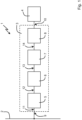
- the system 1 comprises a simplified data bus 2 (in the present embodiment an MVB), an adapter unit 3 and an evaluation unit 4.
- the adapter unit 3 comprises a coupling unit 5, a signal processing unit 6, a decoding unit 7 and an interface module 8.
- the adapter unit 3 has also has a bus input 9 and an output interface 10, which is formed by USB in the present exemplary embodiment.
- the bus input 9 is connected to the data bus 2 , as a result of which a bus signal 11 transmitted via the data bus 2 can reach the bus input 9 and thus the adapter unit 3 .
- a bus signal 11 input into the bus input 9 is input into the coupling unit 5 in which a bus signal 12 coupled over is generated from the bus signal 11 by means of a coupling capacitance (not shown here).
- the overcoupled bus signal 12 is input into the signal processing unit 6 and a processed bus signal 13 is generated there by processing the overcoupled bus signal 12 and is input into the decoding unit 7 .
- the decoding unit 7 decodes bus data encoded in the bus signal 11 and outputs the decoded bus data 14 obtained in this way to the interface module 8 .
- the interface module 8 prepares the decoded bus data 14 for output to the evaluation unit 4 via the output interface 10 .
- bus data encoded in bus signals can be output to an evaluation unit 4 without the evaluation unit 4 or the adapter unit 3 having to have an effect on the data bus 2 .
- an interface change can be made and the output interface 10 can be formed by USB (or another interface).
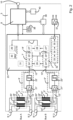
- FIG. 2 shows a more detailed representation of an embodiment of an adapter unit 3.
- the adapter unit 3 has two bus connections, which is shown in 2 marked with "Bus A” and "Bus B".
- the two buses A and B are designed as mutual redundancy.
- Each of the bus inputs 9' and 9" has two connections which enable it to be looped into the bus.
- the connection 9'.1 or 9".1 can be connected to a preceding bus user (not shown) and the connection 9'.2 or 9".2 can be connected to a following bus user (also not shown).
- Each of the connections 9'.1, 9'.2, 9".1 and 9".2 has two poles, which is indicated by two lines extending from the sketched connection. If the bus medium is formed by a twisted pair of lines, for example, one line of the bus medium can be connected to one pole and the other line of the bus medium can be connected to the other pole.
- the bus inputs 9' and 9" are each connected to a coupling unit 5' or 5", each of these coupling units 5' and 5" having a primary-side conductor structure 15' or 15" and a secondary-side conductor structure 16' or 16".
- the primary-side conductor structures 15' and 15" each have a first primary-side conductor section 17' or 17" and a second primary-side conductor section 18' or 18" and the secondary-side conductor structures 16' or 16" have a first secondary-side conductor section 19′ or 19′′ and a second conductor section 20′ or 20′′ on the secondary side.
- These conductor sections 17, 18, 19, 20 are each shown as thickened, parallel straight sections, are part of the respective conductor structure 15, 16 and form pairs a coupling capacitance, namely the first primary-side conductor section 17' or 17" with the first secondary-side conductor section 18' or 18" and the second primary-side conductor section 19' or 19" with the second secondary-side conductor section 20' or 20".
- the conductor sections 17, 18, 19, 20 can be formed by conductor tracks on a circuit board, with the conductor tracks being able to be arranged on four different levels of the circuit board.
- the overcoupled (and differentiated) bus signals 12' and 12" are input from the coupling unit 5' or 5" as differential signals into a signal processing unit 6' or 6".
- the signal processing unit 6' or 6" each includes an amplifier 21 'or 21" with variable, controlled bias and an analog-to-digital converter 22' or 22".
- the amplifier 21' or 21'' respectively amplifies the differential bus signals 12' and 12''.
- the output of the analog/digital converter 22' or 22'' is fed back to the amplifier 21' or 21'', as a result of which the bias of the amplified signal is adjusted depending on a recognized bit.
- the overcoupled bus signal 12′ or 12′′ processed in this way is input as a processed bus signal 13′ or 13′′ into an FPGA—Field Programmable Gate Array—23, in which, among other things, individual units of the adapter unit 3 are implemented.
- the processed bus signal 13' or 13" is input into a decoding unit 7' or 7".
- a function block 24' or 24'' of the decoding unit 7' or 7'' Manchester decoding, frame recognition and error handling at the bit level (in particular error recognition and possible error correction) are carried out.
- a further function block 25' or 25" of the decoding unit 7' or 7" the data frames detected in the bus signal are processed and in this way decoded bus data 14' or 14" are generated and output.
- error detection by means of CRC - Cyclic Redudancy Checking - and/or timeouts and/or filtering for errors, specific message types, senders, addressees or other criteria can be carried out.
- function block 26 the timing of the data transmissions via the two redundant data buses (Bus A, Bus B ) are made.
- the decoded bus data 14' or 14" are entered into a memory 27' or 27", which is designed as a ring memory and holds decoded bus data 14' or 14" ready for later transmission via the interface module 8 to the evaluation unit 4.
- a selection unit 28 is connected to the two memories 27' and 27" and selects the data bus (bus A, bus B) via which a received data frame of better quality was received for the decoded bus data 14' or 14" to be output , contained fewer errors, for example. If bus A and bus B are fully redundant data buses and identical bus signals are transmitted over both data buses, the selection unit 28 selects - ideally - only one set of decoded bus data from two identical copies.
- the data output by the selection unit 28 can nevertheless be regarded as "decoded bus data 14" within the meaning of the present disclosure.
- This decoded bus data 14 is transferred on the one hand to the interface module 8 for output at the output interface 10 and on the other hand to a central control logic 29 which controls functional units implemented in the FPGA 23 .
- the FPGA 23 also includes a central status logic 30, which stores status information within the FPGA 23 and optionally outputs it to a display that is not shown, for example a plurality of LEDs—light-emitting diodes.
- the FPGA 23 also includes RAM 31 - Random Access Memory - for various information, such as filter information.
- a simulation unit 32 which has a memory 33 , reproduction logic 34 , an encoder 35 (for example a Manchester encoder) and a coupling element 36 .
- Test sequences which form a basis for generating a test bus signal, are stored in memory 33, which can be in the form of RAM, for example.
- the playback logic 34 loads the required data from the memory 33 and generates bus data and an interference signal therefrom.
- the bus data are entered into the coder 35 and a bus signal is generated therefrom, which is combined with the interference signal by the coupling element 36 to form the test bus signal.
- This test bus signal is converted via a level converter 37 in such a way that the test bus signal can be further processed internally in the adapter unit as a bus signal.
- This test bus signal can, for example, be routed internally to the decoding unit 7', 7" or applied externally to the bus inputs 9' and 9" via a test adapter.
- a central clock generator 38 for outputting a system clock
- an EEPROM - Electronically Eraseable Read Only Memory - 39 for code for the FPGA 23
- an EEPROM 40 for information for the output interface 10, for example for USB meta information .
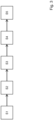
- FIG. 10 shows a flowchart with steps of an embodiment of a method according to the present disclosure.
- a bus signal 11 is first received from the data bus 2 by means of the coupling unit 5 in step S1.
- the coupling unit 5 generates an overcoupled bus signal 12 from the received bus signal 11.
- the signal processing unit 6 generates a processed bus signal 13 from the overcoupled bus signal 12.
- decoded bus data 14 are generated by the decoding unit 7 from the conditioned bus signal 13 .
- the decoded bus data 14 is output to the evaluation unit 4 via the interface module 8 .
Abstract
Es ist eine Adaptereinheit (3) zum Ankoppeln einer Auswerteeinheit (4) an einen Datenbus (2) offenbart, wobei über den Datenbus (2) in Bussignale (11) kodierte Busdaten übertragbar sind. Die Adaptereinheit (3) umfasst:einen Buseingang (9), der zum Empfangen eines Bussignals (11) aus dem Datenbus (2) ausgebildet ist,eine Koppeleinheit (5) mit einer primärseitigen Leiterstruktur (15) und einer sekundärseitigen Leiterstruktur (16), wobei zumindest ein Teil der primärseitigen Leiterstruktur (15) und zumindest ein Teil der sekundärseitigen Leiterstruktur (16) eine Koppelkapazität bilden und wobei die Koppelkapazität derart ausgebildet ist, dass ein Bussignal (11) an dem Buseingang (9) von der primärseitigen Leiterstruktur (15) auf die sekundärseitige Leiterstruktur (16) überkoppelt,eine Signalaufbereitungseinheit (6), die dazu ausgebildet ist, ein auf die sekundärseitige Leiterstruktur (16) übergekoppeltes Bussignal (12) aufzubereiten,eine Dekodiereinheit (7), die dazu ausgebildet ist, Busdaten, die in einem durch die Signalaufbereitungseinheit (6) aufbereiteten Bussignal (13) kodiert sind, zu dekodieren, undein Schnittstellenmodul (8), das dazu ausgebildet ist, durch die Dekodiereinheit (7) dekodierte Busdaten (14) an die Auswerteeinheit (4) auszugeben.Es ist ferner ein System (1) und ein Fahrzeug mit einer entsprechenden Adaptereinheit (3) und ein entsprechendes Verfahren offenbart.An adapter unit (3) for coupling an evaluation unit (4) to a data bus (2) is disclosed, bus data encoded in bus signals (11) being able to be transmitted via the data bus (2). The adapter unit (3) comprises: a bus input (9) which is designed to receive a bus signal (11) from the data bus (2), a coupling unit (5) with a primary-side conductor structure (15) and a secondary-side conductor structure (16), wherein at least part of the conductor structure (15) on the primary side and at least part of the conductor structure (16) on the secondary side form a coupling capacitance and wherein the coupling capacitance is designed in such a way that a bus signal (11) at the bus input (9) from the conductor structure (15) on the primary side coupled to the conductor structure (16) on the secondary side, a signal processing unit (6) which is designed to process a bus signal (12) coupled to the conductor structure (16) on the secondary side, a decoding unit (7) which is designed to process bus data contained in a bus signal (13) processed by the signal processing unit (6), andan interface module (8) which is designed to output bus data (14) decoded by the decoding unit (7) to the evaluation unit (4).It is further discloses a system (1) and a vehicle with a corresponding adapter unit (3) and a corresponding method.
Description
Die vorliegende Offenbarung betrifft eine Adaptereinheit zum Ankoppeln einer Auswerteeinheit an einen Datenbus, vorzugsweise einen Datenbus in einem Fahrzeug, besonders bevorzugter Weise einen Datenbus in einem Schienenfahrzeug. Die vorliegende Offenbarung betrifft ferner ein System und ein Fahrzeug mit einer derartigen Adaptereinheit sowie ein entsprechendes Verfahren.The present disclosure relates to an adapter unit for coupling an evaluation unit to a data bus, preferably a data bus in a vehicle, particularly preferably a data bus in a rail vehicle. The present disclosure also relates to a system and a vehicle with such an adapter unit and a corresponding method.
Datenbusse dienen dem Austausch von Daten zwischen mehreren Teilnehmern des Busses. Die Daten werden dabei in Bussignale kodiert und die Bussignale über ein Busmedium (Kupferkabel, Lichtwellenleiter, etc.) übertragen. Meist erfolgt der Zugriff auf das Busmedium mittels TDMA - Time Division Multiple Access -, weshalb immer nur ein Teilnehmer Daten in den Datenbus senden darf. Ansonsten überschneiden sich die Bussignale der verschiedenen sendenden Teilnehmer und die Datenübertragungen stören sich gegenseitig. Bei einigen Bustechnologien wird eine Sendeberechtigung von einem Master an die Teilnehmer vergeben. Dies kann durch Freigabe einzelner Buszugriffe, durch Zuordnen fester Zeitschlitze für die Teilnehmer, durch Vergabe von Sendekanälen und/oder dergleichen erfolgen. Bei anderen Bustechnologien hören Teilnehmer in den Bus hinein und beginnen zu senden, wenn keine Busaktivität erkennbar ist. Sobald eine Kollision von Datenübertragungen mehrerer Teilnehmer möglich ist, sind Mechanismen zur Kollisionserkennung üblich. Wenn eine Kollision erkannt wird, wird geeignet auf die erkannte Kollision reagiert, beispielsweise wird der Sendevorgang abgebrochen und zu einem späteren Zeitpunkt erneut gestartet.Data buses are used to exchange data between several bus participants. The data is encoded in bus signals and the bus signals are transmitted via a bus medium (copper cable, fiber optic cable, etc.). The bus medium is usually accessed using TDMA - Time Division Multiple Access - which is why only one participant is allowed to send data to the data bus at a time. Otherwise, the bus signals of the various sending participants overlap and the data transmissions interfere with each other. With some bus technologies, a master assigns transmission authorization to the participants. This can be done by enabling individual bus accesses, by allocating fixed time slots for the participants, by allocating transmission channels and/or the like. With other bus technologies, nodes listen into the bus and start sending when no bus activity is detected. As soon as a collision of data transmissions from several participants is possible, mechanisms for collision detection are common. If a collision is detected, a suitable response is made to the detected collision, for example the transmission process is aborted and restarted at a later point in time.
Da ein einziger nicht-konformer Teilnehmer - je nach Ausgestaltung des Datenbusses - die gesamte Buskommunikation stören kann, ist es von Bedeutung, dass sich jeder Teilnehmer des Busses an die jeweiligen Vorgaben hält. Je höher die Sicherheitsanforderungen an eine Kommunikation über den Bus sind, desto wichtiger ist das Einhalten der Vorgaben. Derartige sicherheitsrelevante Busse kommen beispielsweise bei Fahrzeugen zum Einsatz. Teilnehmer, die mit einem derartigen Datenbus verbunden werden sollen, müssen daher meist einen aufwändigen Zertifizierungsprozess durchlaufen, bevor diese für den Betrieb an dem Datenbus zugelassen sind. Bei Schienenfahrzeugen ist der Zertifizierungsaufwand besonders hoch.Since a single non-compliant participant - depending on the design of the data bus - can disrupt the entire bus communication, it is important that each participant on the bus adheres to the respective specifications. The higher the safety requirements for communication via the bus, the more important it is to comply with the specifications. Such safety-related buses are used in vehicles, for example. Subscribers that are to be connected to such a data bus therefore usually have to go through a complex certification process before they are allowed to operate on the data bus allowed are. The certification effort is particularly high for rail vehicles.
Bei vielen Datenbussen gelten diese Anforderungen lediglich für Teilnehmer, die Daten in den Bus senden sollen. Ein Mithören ist meist unproblematisch, da das Mithören üblicherweise die Buskommunikation nicht oder allenfalls vernachlässigbar beeinträchtigt. Entsprechend kann bei mithörenden Teilnehmern eine Zertifizierung entfallen oder deutlich vereinfacht werden, indem beispielsweise lediglich eine Rückwirkungsfreiheit des Teilnehmers auf den Bus nachgewiesen wird.In the case of many data buses, these requirements only apply to participants who are to send data onto the bus. Eavesdropping is usually not a problem, since eavesdropping usually does not impair bus communication or at most negligibly impairs it. Accordingly, in the case of eavesdropping participants, certification can be dispensed with or significantly simplified, for example by merely proving that the participant has no reaction to the bus.
Bei derartigen mithörenden Teilnehmern werden meist Bussignale aus dem Datenbus ausgekoppelt und dem Teilnehmer zugeleitet. Bei Datenbussen, bei denen die Bussignale elektrisch übertragen werden, ist in der Praxis ein induktives oder kapazitives Auskoppeln gebräuchlich. Dennoch ist auch diese mithörende Teilnahme nicht unproblematisch. Denn eine möglichst geringe Rückwirkung eines Teilnehmers auf einen Datenbus bedeutet üblicherweise auch eine möglichst niedrige Koppelinduktivität bzw. Koppelkapazität, wodurch sich Herstellungstoleranzen, unterschiedliche Installationssituationen und/oder andere Rahmenbedingungen erheblich auf die Qualität von ausgekoppelten Bussignalen und deren Verwendbarkeit auswirken können.In the case of such eavesdropping participants, bus signals are usually decoupled from the data bus and fed to the participant. In the case of data buses in which the bus signals are transmitted electrically, inductive or capacitive decoupling is common in practice. Nevertheless, this eavesdropping participation is not unproblematic. Because the lowest possible reaction of a participant to a data bus usually also means the lowest possible coupling inductance or coupling capacitance, which means that manufacturing tolerances, different installation situations and/or other framework conditions can have a significant impact on the quality of bus signals that are decoupled and their usability.
Die
Der vorliegenden Offenbarung liegt die Aufgabe zugrunde, eine Adaptereinheit, ein System, ein Fahrzeug und ein Verfahren bereitzustellen, mit dem eine Auswerteeinheit möglichst flexibel und universell an einen Datenbus ankoppelbar ist, wobei eine möglichst geringe Beeinflussung der Kanaleigenschaften des Busses und eine von verschiedenen Installationssituationen weitgehend unabhängiges Verhalten erstrebenswert ist.The object of the present disclosure is to provide an adapter unit, a system, a vehicle and a method with which an evaluation unit can be coupled to a data bus as flexibly and universally as possible, with the least possible influence on the channel properties of the bus and one of various installation situations independent behavior is desirable.
Diese Aufgabe ist durch eine Adaptereinheit mit den Merkmalen des Anspruchs 1 gelöst. Danach ist die Adaptereinheit zum Ankoppeln einer Auswerteeinheit an einen Datenbus ausgebildet, vorzugsweise einen Datenbus in einem Fahrzeug, besonders bevorzugter Weise einen Datenbus in einem Schienenfahrzeug, wobei über den Datenbus in Bussignale kodierte Busdaten übertragbar sind. Diese Adaptereinheit umfasst:
- einen Buseingang, der zum Verbinden der Adaptereinheit mit dem Datenbus und zum Empfangen eines Bussignals aus dem Datenbus ausgebildet ist,
- eine Koppeleinheit mit einer primärseitigen Leiterstruktur und einer sekundärseitigen Leiterstruktur, wobei die primärseitige Leiterstruktur mit dem Buseingang verbunden ist, wobei zumindest ein Teil der primärseitigen Leiterstruktur und zumindest ein Teil der sekundärseitigen Leiterstruktur eine Koppelkapazität bilden und wobei die Koppelkapazität derart ausgebildet ist, dass ein Bussignal an dem Buseingang von der primärseitigen Leiterstruktur auf die sekundärseitige Leiterstruktur überkoppelt,
- eine Signalaufbereitungseinheit, die dazu ausgebildet ist, ein auf die sekundärseitige Leiterstruktur übergekoppeltes Bussignal aufzubereiten,
- eine Dekodiereinheit, die dazu ausgebildet ist, Busdaten, die in einem durch die Signalaufbereitungseinheit aufbereiteten Bussignal kodiert sind, zu dekodieren, und
- ein Schnittstellenmodul, das dazu ausgebildet ist, durch die Dekodiereinheit dekodierte Busdaten an die Auswerteeinheit auszugeben.
- a bus input designed to connect the adapter unit to the data bus and to receive a bus signal from the data bus,
- a coupling unit with a primary-side conductor structure and a secondary-side conductor structure, with the primary-side conductor structure being connected to the bus input, with at least part of the primary-side conductor structure and at least part of the secondary-side conductor structure forming a coupling capacitance, and with the coupling capacitance being designed in such a way that a bus signal is the bus input is coupled from the primary-side conductor structure to the secondary-side conductor structure,
- a signal processing unit that is designed to process a bus signal that is coupled to the secondary-side conductor structure,
- a decoding unit which is designed to decode bus data which is encoded in a bus signal which has been conditioned by the signal conditioning unit, and
- an interface module which is designed to output bus data decoded by the decoding unit to the evaluation unit.
Hinsichtlich eines Systems ist diese Aufgabe durch die Merkmale des Anspruchs 13, hinsichtlich eines Fahrzeugs durch die Merkmale des Anspruchs 14 und hinsichtlich eines Verfahrens durch die Merkmale des Anspruchs 15 gelöst.With regard to a system, this object is achieved by the features of
Weitere Ausgestaltungen sind in den Unteransprüchen offenbart.Further developments are disclosed in the dependent claims.
Es sei darauf hinzuweisen, dass die in den Ansprüchen einzeln aufgeführten Merkmale in beliebiger, technisch sinnvoller Weise miteinander kombiniert werden können und weitere Ausgestaltungen der vorliegenden Offenbarung aufzeigen. Die Beschreibung charakterisiert und spezifiziert die vorliegende Offenbarung insbesondere im Zusammenhang mit den Figuren zusätzlich.It should be pointed out that the features listed individually in the claims can be combined with one another in any technically meaningful way and show further refinements of the present disclosure. The description additionally characterizes and specifies the present disclosure, in particular in connection with the figures.
Es sei ferner angemerkt, dass eine hierin verwendete, zwischen zwei Merkmalen stehende und diese miteinander verknüpfende Konjunktion "und/oder" stets so auszulegen ist, dass in einer ersten Ausgestaltung des offenbarten Gegenstands lediglich das erste Merkmal vorhanden sein kann, in einer zweiten Ausgestaltung lediglich das zweite Merkmal und in einer dritten Ausgestaltung sowohl das erste als auch das zweite Merkmal.It should also be noted that a conjunction "and/or" used herein, standing between two features and linking them to one another, must always be interpreted in such a way that in a first embodiment of the disclosed subject matter only the first feature can be present, in a second embodiment only the second feature and in a third embodiment both the first and the second feature.
Es ist erkannt worden, dass eine Adaptereinheit dann besonders universell einsetzbar ist und den Bus möglichst wenig beeinflusst, wenn die Kopplung von Bussignalen zwischen Bus und Adaptereinheit auf nachvollziehbare und deterministische Weise erfolgt. Daher umfasst die Adaptereinheit der vorliegenden Offenbarung eine Koppeleinheit mit einer primärseitigen Leiterstruktur und einer sekundärseitigen Leiterstruktur. Die Adaptereinheit wird über einen Buseingang mit dem Datenbus verbunden. Dieser Buseingang ist wiederum mit der primärseitigen Leiterstruktur verbunden. Dadurch können auf dem Datenbus übertragene Bussignale in die Koppeleinheit und auf die primärseitige Leiterstruktur gelangen. Die primärseitige Leiterstruktur und die sekundärseitige Leiterstruktur sind derart angeordnet und ausgebildet, dass eine kapazitive Kopplung zwischen zumindest einem Teil der primärseitigen Leiterstruktur und zumindest einem Teil der sekundärseitigen Leiterstruktur entsteht. Dadurch können Bussignale über eine derart gebildete Koppelkapazität in definierter Weise auf die sekundärseitige Leiterstruktur überkoppeln. Da diese Koppeleinheit in allen Installationssituationen dieselben Koppeleigenschaften aufweist, ist der Betrieb der Adaptereinheit im Wesentlichen von der Installationssituation unabhängig.It has been recognized that an adapter unit can be used particularly universally and affects the bus as little as possible if the coupling of bus signals between the bus and adapter unit takes place in a traceable and deterministic manner. Therefore, the adapter unit of the present disclosure includes a coupling unit with a primary-side conductor structure and a secondary-side conductor structure. The adapter unit is connected to the data bus via a bus input. This bus input is in turn connected to the conductor structure on the primary side. As a result, bus signals transmitted on the data bus can reach the coupling unit and the conductor structure on the primary side. The primary-side conductor structure and the secondary-side conductor structure are arranged and formed in such a way that a capacitive coupling occurs between at least a part of the primary-side conductor structure and at least a part of the secondary-side conductor structure. As a result, bus signals can couple over to the secondary-side conductor structure in a defined manner via a coupling capacitance formed in this way. Since this coupling unit has the same coupling properties in all installation situations, the operation of the adapter unit is essentially independent of the installation situation.
Ein übergekoppeltes Bussignal, das von dem in den Buseingang eingegebenen Bussignal herrührt und auf die sekundärseitige Leiterstruktur kapazitiv übergekoppelt ist, wird in eine Signalaufbereitungseinheit eingegeben. Dort wird das übergekoppelte Bussignal aufbereitet und dadurch ein aufbereitetes Bussignal erzeugt.An overcoupled bus signal, which originates from the bus signal input into the bus input and is capacitively overcoupled onto the secondary-side conductor structure, is input into a signal conditioning unit. The overcoupled bus signal is processed there and a processed bus signal is thereby generated.
Das aufbereitete Bussignal wird in eine Dekodiereinheit eingegeben, die in dem aufbereiteten Bussignal kodierte Busdaten dekodiert und daraus dekodierte Busdaten erzeugt und ausgibt. Die dekodierten Busdaten werden in ein Schnittstellenmodul eingegeben, das die dekodierten Busdaten an die Auswerteeinheit ausgeben kann. Auf diese Weise können über den Datenbus übertragene Busdaten aus dem Datenbus in deterministischer Weise ausgekoppelt werden und auf verschiedenste Weise einer Auswerteeinheit zugeleitet werden. Durch die Nutzung eines separaten Schnittstellenmoduls sind die an die Auswerteeinheit ausgegebenen Busdaten äußerst flexibel nutzbar und weitgehend von dem eingesetzten Datenbus unabhängig. Dies ermöglicht auch einen Schnittstellenwechsel, was wiederum einen besonders universellen Einsatz ermöglicht. Generell bietet eine derartige Adaptereinheit einen transparenten und im Wesentlichen rückwirkungsfreien Zugriff auf den Datenbus. Durch den universellen Aufbau kann die Adaptereinheit in bestehende Datenbusse nachgerüstet werden, was die Einsetzbarkeit der Adaptereinheit noch universeller werden lässt.The processed bus signal is input into a decoding unit, which decodes bus data encoded in the processed bus signal and generates and outputs decoded bus data therefrom. The decoded bus data are entered into an interface module that can output the decoded bus data to the evaluation unit. In this way, bus data transmitted via the data bus can be decoupled from the data bus in a deterministic manner and fed to an evaluation unit in a wide variety of ways. By using a separate interface module, the bus data output to the evaluation unit can be used extremely flexibly and are largely independent of the data bus used. This also enables an interface change, which in turn enables particularly universal use. In general, such an adapter unit offers transparent and essentially reaction-free access to the data bus. Due to the universal design, the adapter unit can be retrofitted into existing data buses, which makes the adapter unit even more universally applicable.
Eine "Auswerteeinheit", die mit der Adaptereinheit verbunden werden kann, kann durch verschiedenste lesende Endgeräte gebildet sein. Eine derartige Auswerteeinheit kann die empfangenen Busdaten auf verschiedenste Weise auswerten, wobei das "Auswerten" im weitesten Sinne verstanden werden kann. Dieses "Auswerten" kann beispielsweise ein Abspeichern empfangener Busdaten im Sinne eines Datenloggers umfassen. Die Auswerteeinheit kann ein dauerhaftes Monitoring des Datenbusses und der dort übertragenen Kommunikation durchführen. Es kann eine Interpretation der Busdaten und des Kommunikationsverhaltens des Busses vorgenommen und dessen Teilnehmer überwacht werden. Es ist auch denkbar, dass die Auswerteeinheit die empfangenen Busdaten für eine Fehlersuche nutzt, wenn beispielsweise eine Busnachricht eines Busteilnehmers nicht bei einem anderen Busteilnehmer ankommt. Diese kurze, nicht abschließende und insbesondere nicht beschränkend zu betrachtende Aufzählung denkbarer Auswerteeinheiten zeigt, wie universell die Adaptereinheit eingesetzt werden kann.An "evaluation unit" that can be connected to the adapter unit can be formed by a wide variety of reading terminals. Such an evaluation unit can evaluate the received bus data in a wide variety of ways, with "evaluation" being understood in the broadest sense. This “evaluation” can include, for example, storing received bus data in the sense of a data logger. The evaluation unit can carry out permanent monitoring of the data bus and the communication transmitted there. The bus data and the communication behavior of the bus can be interpreted and its participants can be monitored. It is also conceivable for the evaluation unit to use the received bus data for troubleshooting if, for example, a bus message from one bus user does not arrive at another bus user. This short, non-exhaustive and, in particular, non-limiting listing of conceivable evaluation units shows how universally the adapter unit can be used.
Der "Datenbus" kann durch verschiedenste Busse gebildet sein. Wichtig ist, dass über den Datenbus Busdaten übertragen und diese für eine Auswerteeinheit zugänglich gemacht werden können. Dabei können die verschiedensten Busmedien eingesetzt werden, die verschiedenste Übertragungen ermöglichen, beispielsweise elektrisch, optisch, per Funk, etc.The "data bus" can be formed by a wide variety of buses. It is important that bus data can be transmitted via the data bus and made accessible to an evaluation unit. A wide variety of bus media can be used are used that enable a wide variety of transmissions, for example electrical, optical, wireless, etc.
Gleichzeitig kann der Zugriff auf den Bus auf verschiedenste Weise realisiert sein. Beispielhaft sei TDMA - Time Division Multiple Access -, FDMA - Frequency Division Multiple Access - und CDMA - Code Division Multiple Access - genannt. Die Bussignale können verschiedentlich moduliert sein, beispielsweise mittels PSK - Phase Shift Keying -, FSK - Frequency Shift Keying - oder ASK - Amplitude Shift Keying -, um auch hier lediglich einige denkbare Modulationsarten zu nennen. Üblicherweise wird die jeweils verwendete Bustechnologie die jeweilige Übertragung definieren oder zumindest auf eine gewisse Anzahl von Optionen reduzieren.At the same time, access to the bus can be implemented in a wide variety of ways. Examples include TDMA—Time Division Multiple Access—FDMA—Frequency Division Multiple Access—and CDMA—Code Division Multiple Access. The bus signals can be modulated in various ways, for example using PSK—phase shift keying—, FSK—frequency shift keying—or ASK—amplitude shift keying—to name just a few conceivable types of modulation. The bus technology used in each case will usually define the respective transmission or at least reduce it to a certain number of options.
Abhängig von der Ausgestaltung des Datenbusses dürfte auch der "Buseingang" ausgestaltet sein. Dies kann beispielsweise eine Anpassung an das jeweils eingesetzte Busmedium beinhalten. Wenn der Datenbus beispielsweise ein Kupferkabel als Busmedium nutzt, sollte der Buseingang zum Verbinden mit diesem Kupferkabel ausgestaltet sein. Wenn der Datenbus einen Lichtwellenleiter, beispielsweise eine Glasfaser, nutzt, sollte der Buseingang zum Verbinden mit diesem Lichtwellenleiter ausgebildet sein. Entsprechend empfiehlt es sich, wenn der Buseingang eine angepasste Anzahl von Polen aufweist. Wenn der Datenbus beispielsweise zwei verdrillte Drähte zur Übertragung der Bussignale nutzt, sollte der Buseingang zwei Pole aufweisen. Nicht selten werden bei Datenbussen die einzelnen Busteilnehmer hintereinandergeschaltet, sodass ein Busteilnehmer sowohl einen Anschluss zu dem vorhergehenden Busteilnehmer als auch einen Anschluss zu einem nachfolgenden Busteilnehmer aufweist. Entsprechend kann auch der Buseingang derartige Anschlüsse für vorhergehende und nachfolgende Busteilnehmer aufweisen. Diese nicht abschließende Auflistung zeigt, auf welche Weise beispielsweise eine Anpassung zwischen Datenbus und Buseingang erfolgen kann.Depending on the configuration of the data bus, the “bus input” should also be configured. This can include, for example, an adaptation to the bus medium used in each case. For example, if the data bus uses a copper cable as the bus medium, the bus input should be designed to connect to this copper cable. If the data bus uses an optical waveguide, for example a glass fiber, the bus input should be designed for connection to this optical waveguide. Accordingly, it is advisable if the bus input has an adjusted number of poles. For example, if the data bus uses two twisted-pair wires to transmit the bus signals, the bus input should have two pins. It is not uncommon for data buses to have the individual bus users connected in series, so that a bus user has both a connection to the preceding bus user and a connection to a subsequent bus user. Correspondingly, the bus input can also have such connections for preceding and following bus subscribers. This non-exhaustive listing shows how, for example, an adaptation between the data bus and the bus input can take place.
"Bussignale" können prinzipiell alle Signale sein, die über einen Datenbus übertragen werden und in denen Busdaten kodiert sein können. Je nach Ausgestaltung des Busmediums dürften sich auch die Bussignale unterscheiden. So kann bei einem optischen Busmedium das Bussignal ein Laserstrahl sein, der in seiner Intensität moduliert wird. Bei einem Kupferkabel als Busmedium kann das Bussignal ein elektrisches Signal sein. Ohne Beschränkung der Allgemeinheit wird nachfolgend davon ausgegangen, dass das Bussignal ein elektrisches Signal ist. Dabei kann das elektrische Signal direkt auf dem Bus übertragen werden. Allerdings ist auch denkbar, dass optische Signale, elektromagnetische Signale oder dergleichen für die Übertragung der Busdaten über den Bus genutzt werden. Da derartige Signale für die weitere Bearbeitung üblicherweise in elektrische Signale gewandelt werden, stellt die Annahme eines Bussignals als elektrisches Signal keine Beschränkung der Allgemeinheit dar. Die Bussignale können auf unterschiedliche Weise kodiert sein, unterschiedlichste Pegel annehmen oder unterschiedlichste Frequenzen nutzen, um lediglich einige Beispiele zu nennen."Bus signals" can in principle be all signals that are transmitted via a data bus and in which bus data can be encoded. Depending on the design of the bus medium, the bus signals may also differ. In the case of an optical bus medium, for example, the bus signal can be a laser beam whose intensity is modulated. With a copper cable as the bus medium, the bus signal can be an electrical signal. Without loss of generality, the following assumed that the bus signal is an electrical signal. The electrical signal can be transmitted directly on the bus. However, it is also conceivable that optical signals, electromagnetic signals or the like are used for the transmission of the bus data via the bus. Since such signals are usually converted into electrical signals for further processing, the assumption of a bus signal as an electrical signal does not represent a restriction of generality. The bus signals can be coded in different ways, have different levels or use different frequencies, to give just a few examples to name.
Auch die "primärseitige Leiterstruktur" und die "sekundärseitige Leiterstruktur" können auf verschiedentliche Arten realisiert sein. Wichtig ist, dass sich zwischen zumindest Teilen dieser Leiterstrukturen eine Koppelkapazität ausbildet, d.h. ein Bereich, in dem ein elektrisches Signal von der primärseitigen Leiterstruktur mittels eines elektrischen Felds in die sekundärseitige Leiterstruktur überkoppeln kann. Diese Voraussetzung lässt sich auf verschiedene, aus der Praxis bekannte Weisen realisieren.The "primary-side conductor structure" and the "secondary-side conductor structure" can also be realized in various ways. It is important that a coupling capacitance forms between at least parts of these conductor structures, i.e. an area in which an electrical signal can couple from the primary-side conductor structure to the secondary-side conductor structure by means of an electrical field. This prerequisite can be realized in various ways known from practice.
Dabei kann die gesamte primärseitige Leiterstruktur und die gesamte sekundärseitige Leiterstruktur diese Koppelkapazität bilden. Es ist aber auch denkbar, dass lediglich ein Teilabschnitt der primärseitigen Leiterstruktur und/oder der sekundärseitigen Leiterstruktur zum Bilden dieser Koppelkapazität beitragen, wobei verbleibende Teile beispielsweise als Zuleitung für die Teilabschnitte der Koppelkapazität dienen. Der zumindest eine Teil der primärseitigen Leiterstruktur und der zumindest eine Teil der sekundärseitigen Leiterstruktur können sich dabei relativ beliebig erstrecken. In einer Ausgestaltung sind die Teile durch gerade Leiterabschnitte gebildet. In einer anderen Ausgestaltung sind die Teile gebogen, beispielsweise als Kreisbogen, als Ausschnitt einer Ellipse oder als sonstige gebogene Kurve. Dabei kann es sich anbieten, dass die primärseitige Leiterstruktur und die sekundärseitige Leiterstruktur keine ausgeprägten Ecken aufweisen, um beispielsweise bei höheren Frequenzen des Bussignals eine elektromagnetische Abstrahlung zu reduzieren oder gar zu vermeiden.In this case, the entire conductor structure on the primary side and the entire conductor structure on the secondary side can form this coupling capacitance. However, it is also conceivable for only a section of the primary-side conductor structure and/or the secondary-side conductor structure to contribute to the formation of this coupling capacitance, with the remaining parts serving, for example, as feed lines for the sections of the coupling capacitance. The at least one part of the primary-side conductor structure and the at least one part of the secondary-side conductor structure can extend relatively arbitrarily. In one embodiment, the parts are formed by straight conductor sections. In another embodiment, the parts are curved, for example as an arc of a circle, as a section of an ellipse or as some other curved curve. In this case, it may be advisable for the conductor structure on the primary side and the conductor structure on the secondary side to have no pronounced corners, in order to reduce or even avoid electromagnetic radiation at higher frequencies of the bus signal, for example.
Die primärseitige Leiterstruktur und/oder die sekundärseitige Leiterstruktur können in einer Ausgestaltung jeweils durch einen einzelnen Leiter gebildet sein. In einer anderen Ausgestaltung umfasst die primärseitige Leiterstruktur und/oder die sekundärseitige Leiterstruktur mehrere parallel geschaltete Leiter, von denen jeweils mindestens ein Teil der Leiterstruktur einen Beitrag zu der Koppelkapazität leisten kann.In one configuration, the primary-side conductor structure and/or the secondary-side conductor structure can each be formed by a single conductor. In In another configuration, the conductor structure on the primary side and/or the conductor structure on the secondary side comprises a plurality of conductors connected in parallel, of which at least part of the conductor structure can contribute to the coupling capacitance.
Bei elektrischen Datenbussen kann das Busmedium durch zwei Leiter aufgespannt sein, über die das Bussignal differenziell aufgeprägt wird. Bei Verwendung derartiger mehrteiliger Busmedien kann auch die primärseitige Leiterstruktur und/oder die sekundärseitige Leiterstruktur mehrteilig aufgebaut sein. Bei einem Busmedium mit einem ersten Busleiter und einem zweiten Busleiter kann die primärseitige Leiterstruktur einen ersten primärseitigen Leiterabschnitt und einen zweiten primärseitigen Leiterabschnitt aufweisen. Der erste Busleiter kann dann mit dem ersten primärseitigen Leiterabschnitt und der zweite Busleiter mit dem zweiten primärseitigen Leiterabschnitt verbunden sein. Entsprechend würde auch die sekundärseitige Leiterstruktur einen ersten sekundärseitigen Leiterabschnitt und einen zweiten sekundärseitigen Leiterabschnitt umfassen, wobei der erste primärseitige Leiterabschnitt und der erste sekundärseitige Leiterabschnitt eine erste Koppelkapazität bilden und der zweite primärseitige Leiterabschnitt und der zweite sekundärseitige Leiterabschnitt eine zweite Koppelkapazität. Auf diese Weise kann das Signal an dem ersten Busleiter auf den ersten sekundärseitigen Leiterabschnitt und das Signal an dem zweiten Busleiter auf den zweiten sekundärseitigen Leiterabschnitt überkoppeln. Die Signale an den beiden sekundärseitigen Leiterabschnitten können dann beispielsweise mit einem Differenzverstärker abgegriffen und verstärkt werden.In the case of electrical data buses, the bus medium can be spanned by two conductors, via which the bus signal is impressed differentially. When using such multi-part bus media, the conductor structure on the primary side and/or the conductor structure on the secondary side can also be constructed in multiple parts. In the case of a bus medium with a first bus conductor and a second bus conductor, the conductor structure on the primary side can have a first conductor section on the primary side and a second conductor section on the primary side. The first bus conductor can then be connected to the first conductor section on the primary side and the second bus conductor can be connected to the second conductor section on the primary side. Correspondingly, the secondary-side conductor structure would also comprise a first secondary-side conductor section and a second secondary-side conductor section, with the first primary-side conductor section and the first secondary-side conductor section forming a first coupling capacitance and the second primary-side conductor section and the second secondary-side conductor section forming a second coupling capacitance. In this way, the signal on the first bus conductor can couple onto the first conductor section on the secondary side and the signal on the second bus conductor can couple over onto the second conductor section on the secondary side. The signals at the two conductor sections on the secondary side can then be tapped and amplified, for example, with a differential amplifier.
Das "Schnittstellenmodul" ist dazu ausgebildet, dekodierte Busdaten an die Auswerteeinheit auszugeben. Die Ausgabe der dekodierten Busdaten dürfte üblicherweise über eine entsprechend ausgebildete Schnittstelle erfolgen. Die Adaptereinheit kann daher eine entsprechende Ausgabeschnittstelle aufweisen. Das Schnittstellenmodul gibt die dekodierten Daten dann - geeignet kodiert - über die Ausgabeschnittstelle an die Auswerteeinheit aus. Die Ausgabeschnittstelle kann dabei trennbar ausgebildet sein. Hierfür kann eine Steckerverbindung vorgesehen sein.The "interface module" is designed to output decoded bus data to the evaluation unit. The decoded bus data should usually be output via an appropriately designed interface. The adapter unit can therefore have a corresponding output interface. The interface module then outputs the decoded data—suitably encoded—to the evaluation unit via the output interface. The output interface can be designed so that it can be separated. A plug connection can be provided for this purpose.
Die Adaptereinheit kann auf verschiedenste Weise implementiert sein. Eine Implementierung durch reine Hardware ist ebenso denkbar wie eine Implementierung in reiner Software. Vorzugsweise ist die Adaptereinheit jedoch durch eine Kombination von Software und Hardware implementiert. Dabei kann ein Mikroprozessor, ein Mikrocontroller und/oder ein anderer programmierbarer Logikbaustein (beispielsweise FPGA - Field Programmable Gate Array -, CPLD - Complex Programmable Logic Device -, ASIC - Application Programmable Integrated Circuit -, etc.) zum Einsatz kommen.The adapter unit can be implemented in many different ways. An implementation by pure hardware is just as conceivable as an implementation in pure software. However, preferably the adapter unit is implemented by a combination of software and hardware. A microprocessor, a microcontroller and/or another programmable logic module (for example FPGA—Field Programmable Gate Array—, CPLD—Complex Programmable Logic Device—, ASIC—Application Programmable Integrated Circuit—, etc.) can be used.
In einer Ausgestaltung sind der zumindest eine Teil der primärseitigen Leiterstruktur und der zumindest eine Teil der sekundärseitigen Leiterstruktur, die gemeinsam die Koppelkapazität bilden, durch parallele Leiter gebildet. Diese parallelen Leiter können durch parallel verlaufende Geradenstücke gebildet sein. Als "parallele Leiter" in diesem Sinne können aber auch Kurven angesehen werden, die in einem annähernd gleichen Abstand zueinander verlaufen. So können beispielsweise Kreisbogen mit einem gleichen Mittelpunkt und unterschiedlichen Radien parallele Leiter bilden. Parallele Leiter bieten den Vorteil, dass eine Koppelkapazität mit gut steuer- und berechenbarem Kapazitätswert entstehen kann.In one configuration, the at least one part of the conductor structure on the primary side and the at least one part of the conductor structure on the secondary side, which together form the coupling capacitance, are formed by parallel conductors. These parallel conductors can be formed by parallel straight sections. However, curves that run at approximately the same distance from one another can also be regarded as "parallel conductors" in this sense. For example, arcs of circles with the same center and different radii can form parallel conductors. Parallel conductors offer the advantage that a coupling capacitance with a capacitance value that can be easily controlled and calculated can arise.
In einer Ausgestaltung sind der zumindest eine Teil der primärseitigen Leiterstruktur und der zumindest eine Teil der sekundärseitigen Leiterstruktur, die gemeinsam die Koppelkapazität bilden, durch Leiter auf einer Platine gebildet, wobei die Leiter vorzugsweise auf unterschiedlichen Ebenen der Platine angeordnet sind. Leiter auf einer Platine bieten den Vorteil, dass ihre relative Lage zumindest in einer Richtung durch die Platine eindeutig definiert ist. Dies kann die Herstellung der Koppelkapazität vereinfachen. Wenn die Leiter auf unterschiedlichen Ebenen der Platine angeordnet sind, ergibt sich zudem der Vorteil, dass die Leiter besser eine Koppelkapazität bilden können. Denn die Leiter auf einer Platine sind meist breiter als dick, sodass sich besser elektrische Felder zwischen den Leitern ausbilden können. Wenn die Platine auf mehr als zwei Ebenen Leiter aufweist, kann zudem die Feldverteilung besser gesteuert und eventuell - je nach Anordnung der Leiter - eine Abschirmung gegenüber externen Einstreuungen erreicht werden.In one configuration, the at least one part of the primary-side conductor structure and the at least one part of the secondary-side conductor structure, which together form the coupling capacitance, are formed by conductors on a circuit board, with the conductors preferably being arranged on different levels of the circuit board. Conductors on a circuit board offer the advantage that their relative position is clearly defined at least in one direction through the circuit board. This can simplify the production of the coupling capacitance. If the conductors are arranged on different levels of the circuit board, there is also the advantage that the conductors can better form a coupling capacitance. Because the conductors on a circuit board are usually wider than they are thick, so that electrical fields can form better between the conductors. If the circuit board has conductors on more than two levels, the field distribution can also be better controlled and, depending on the arrangement of the conductors, shielding against external interference can be achieved.
In einer Ausgestaltung weist die Koppelkapazität einen Kapazitätswert auf, der so klein ist, dass ein über den Bus übertragenes Bussignal durch die Koppelkapazität im Wesentlichen unbeeinflusst bleibt. Wie hoch der Kapazitätswert konkret ist, hängt üblicherweise von dem eingesetzten Datenbus, der Länge des Datenbusses, der konkret verwendeten Übertragungstechnik und vielen weiteren Faktoren ab. In einer Weiterbildung ist der Kapazitätswert im Pikofarad-Bereich.In one configuration, the coupling capacitance has a capacitance value that is so small that a bus signal transmitted via the bus remains essentially unaffected by the coupling capacitance. The specific capacitance value usually depends on the data bus used, the length of the data bus, the specific transmission technology used and many other factors. In a further development, the capacitance value is in the picofarad range.
In einer Ausgestaltung weist die Koppelkapazität einen Kapazitätswert zwischen 0,1 Pikofarad und 10 Pikofarad, vorzugsweise zwischen 1 Pikofarad und 5 Pikofarad auf. Diese Werte liefern beispielsweise bei einem MVB gute Ergebnisse und können eine ausreichend gute Überkopplung des Bussignals in die sekundärseitige Leiterstruktur erreichen.In one embodiment, the coupling capacitance has a capacitance value between 0.1 picofarad and 10 picofarad, preferably between 1 picofarad and 5 picofarad. These values provide good results with an MVB, for example, and can achieve sufficiently good overcoupling of the bus signal into the conductor structure on the secondary side.
In einer Ausgestaltung weist die Signalaufbereitungseinheit einen Filter, einen Verstärker und/oder einen Analog-Digital-Wandler auf. Dabei ist der Filter vorzugsweise ein Bandpassfilter. Der Filter kann dazu eingesetzt werden, in das Bussignal eingekoppelte Störungen zu reduzieren. Ein Bandpassfilter kann dabei das erwartete Spektrum des Bussignals isolieren. Ein Verstärker kann das eingekoppelte Bussignal, das einen relativ niedrigen Pegel aufweisen dürfte, verstärken. Der Verstärker kann auch als Differenzverstärker ausgebildet sein, der eine Differenz zwischen zwei eingegebenen Signalen - beispielsweise zwischen dem zuvor angeführten ersten sekundärseitigen Leiterabschnitt und dem zweiten sekundärseitigen Leiterabschnitt - verstärkt. Ein Filter kann vor dem Verstärker und/oder nach dem Verstärker angeordnet sein. Ein Analog-Digital-Wandler kann aus dem analogen Bussignal ein digitales Signal erzeugen, das in der Dekodiereinheit dann digital verarbeitet werden kann.In one configuration, the signal processing unit has a filter, an amplifier and/or an analog/digital converter. In this case, the filter is preferably a bandpass filter. The filter can be used to reduce noise coupled into the bus signal. A bandpass filter can isolate the expected spectrum of the bus signal. An amplifier can amplify the injected bus signal, which should be at a relatively low level. The amplifier can also be a differential amplifier which amplifies a difference between two input signals, for example between the aforementioned first secondary-side conductor section and the second secondary-side conductor section. A filter can be placed before the amplifier and/or after the amplifier. An analog-to-digital converter can generate a digital signal from the analog bus signal, which can then be processed digitally in the decoding unit.
In einer Ausgestaltung wird das übergekoppelte Bussignal in den Verstärker eingegeben, erzeugt der Verstärker durch Verstärkung des übergekoppelten Bussignals ein verstärktes Bussignal, das in den Analog-Digital-Wandler eingegeben wird, und erzeugt der Analog-Digital-Wandler durch Digitalisierung des verstärkten Bussignals ein digitalisiertes Bussignal, wobei das digitalisierte Bussignal als positive Rückkopplung in den Verstärker eingegeben wird. Diese Ausgestaltung bietet den Vorteil, dass die Aufbereitung des übergekoppelten Bussignals deutlich verbessert werden kann. Denn durch diese besondere Verschaltung können die Bedingungen einer Übertragung und eventuelle Störungen besser erkannt werden. Durch kapazitive Auskopplung des Bussignals gehen gewisse Informationen verloren, beispielsweise der jeweilige Spannungspegel, ein Ruhepegel, eine genaue Spannungsdifferenz und/oder andere Bedingungen der Übertragung. Nach der Koppeleinheit sind im Wesentlichen lediglich Informationen über Änderungen des Bussignals verfügbar. Dadurch ist eine Unterscheidung schwieriger, ob eine Pegeländerung oder eine Störung empfangen worden ist. Für eine Rekonstruktion der Busdaten ist diese Unterscheidung aber von Interesse, bei Störungen insbesondere, ob eine Gleichtakt- oder eine Gegentaktstörung vorliegt. Bei Datenbussen, die ein Leitungspaar zur Übertragung nutzen, beispielsweise RS485, RS422, ProfiBus, CAN-Bus, Ethernet oder MVB, wirken sich Gleichtaktstörungen auf beide Busleitungen aus, sodass ein differentielles Signal nicht beeinflusst wird. Gegentaktstörungen wirken sich jedoch auf ein differentielles Signal aus, wodurch wiederum Dateninhalte gestört werden können. Eine Rückkopplung eines zuletzt erkannten Signalpegels kann die Störfestigkeit deutlich verbessern und das Erkennen von Startbedingungen einer Übertragung beschleunigen.In one embodiment, the overcoupled bus signal is input to the amplifier, the amplifier generates an amplified bus signal by amplifying the overcoupled bus signal, which is input to the analog-to-digital converter, and the analog-to-digital converter generates a digitized one by digitizing the amplified bus signal Bus signal, where the digitized bus signal is input to the amplifier as positive feedback. This refinement offers the advantage that the processing of the overcoupled bus signal can be significantly improved. Because of this special interconnection, the conditions of a transmission and possible disturbances can be recognized better. Certain information is lost as a result of capacitive decoupling of the bus signal, for example the respective voltage level, an idle level, an exact voltage difference and/or other transmission conditions. After the coupling unit essentially only information about changes in the bus signal is available. This makes it more difficult to distinguish whether a level change or interference has been received. For a reconstruction of the bus data, however, this distinction is of interest, in the case of faults, in particular whether there is common-mode or differential-mode interference. In the case of data buses that use a pair of wires for transmission, such as RS485, RS422, ProfiBus, CAN bus, Ethernet or MVB, common-mode interference affects both bus lines so that a differential signal is not affected. However, differential mode interference affects a differential signal, which in turn can interfere with data content. Feedback on a signal level that was recognized last can significantly improve the interference immunity and speed up the recognition of the start conditions of a transmission.
In einer Ausgestaltung ist die Dekodiereinheit auf die Kodierung des Bussignals des Busses angepasst und führt vorzugsweise eine Manchester-Dekodierung, eine Frame-Erkennung, eine Fehlererkennung und/oder eine Fehlerbehebung durch. Durch diese Anpassung können die verschiedenen Bestandteile der Dekodiereinheit noch bessere Ergebnisse liefern. Eine Frame-Erkennung kann insbesondere bei Datenbussen interessant sein, bei denen die Busdaten in Datenrahmen - sogenannte Frames - übertragen werden. Wenn ein Frame erkannt wird, begünstigt dies die Dekodierung der Busdaten. Eine Fehlererkennung kann fehlerhaft übermittelte Busdaten erkennen. Da die Adaptereinheit üblicherweise lediglich in die Buskommunikation hineinhört und keinen Sendekanal nutzt, kann der Quelle der fehlerhaft übermittelten Busdaten nicht mitgeteilt werden, dass Daten fehlerhaft übermittelt worden sind. Diese Information kann dennoch sinnvoll genutzt werden. Denn fehlerhafte Daten sind eventuell durch eine Fehlerbehebung korrigierbar, die fehlerhaft übermittelten Busdaten werden möglicherweise auch bei der Senke fehlerbehaftet angekommen und erneut angefragt, fehlerhaft empfangene Busdaten liefern eventuell Informationen für die verbundene Auswerteeinheit, beispielsweise hinsichtlich eines Erkennens einer generell fehlerhaften Buskommunikation, etc.In one refinement, the decoding unit is adapted to the coding of the bus signal of the bus and preferably carries out Manchester decoding, frame recognition, error recognition and/or error correction. This adaptation enables the various components of the decoding unit to deliver even better results. Frame recognition can be of particular interest in the case of data buses in which the bus data is transmitted in data frames—so-called frames. If a frame is detected, this favors the decoding of the bus data. Error detection can detect incorrectly transmitted bus data. Since the adapter unit usually only listens into the bus communication and does not use a transmission channel, the source of the incorrectly transmitted bus data cannot be informed that data has been incorrectly transmitted. Nonetheless, this information can be useful. Because faulty data can possibly be corrected by troubleshooting, the incorrectly transmitted bus data may also arrive at the sink with errors and be requested again, incorrectly received bus data may provide information for the connected evaluation unit, for example with regard to recognizing a generally faulty bus communication, etc.
In einer Ausgestaltung umfasst die Adaptereinheit einen Zeitgeber und einen Zeitstempler, wobei der Zeitgeber eine Zeitreferenz liefert und wobei der Zeitstempler dazu ausgebildet ist, dekodierte Busdaten unter Nutzung der Zeitreferenz mit einem Zeitstempel zu versehen. Ein Zeitgeber ermöglicht es, eine Zeitreferenz zu halten, ohne dass eine dauerhafte Kommunikationsverbindung zu einem externen Zeitgeber vorhanden sein muss. Zur Synchronisation des Zeitgebers kann dennoch ein externer Zeitgeber erreichbar sein, mit dessen Hilfe die Zeitreferenz des Zeitgebers eingestellt werden kann. Entsprechende externe Zeitgeber könnten beispielsweise ein Zeitsender nach DCF77, ein NTP - Network Time Procotol - Server oder dergleichen sein. Der Zeitstempler erlaubt, dekodierte Busdaten in einen zeitlichen Kontext zu setzen. Dies kann beispielsweise bei einer Fehleranalyse der Busdaten durch die Auswerteeinheit hilfreich sein. Der Zeitstempel, den der Zeitstempler erzeugt, basiert auf der Zeitreferenz des Zeitgebers und würde in einem Datensatz an die dekodierten Busdaten angehängt. Dieser Datensatz kann dann abgespeichert und/oder über das Schnittstellenmodul an die Auswerteinheit ausgegeben werden.In one configuration, the adapter unit comprises a timer and a time stamp, the timer supplying a time reference and the time stamp being designed to provide decoded bus data with a time stamp using the time reference. A timer allows a time reference to be made hold without the need for a permanent communication link to an external timer. An external timer can still be reached for synchronization of the timer, with the help of which the time reference of the timer can be set. Corresponding external clocks could be, for example, a time transmitter based on DCF77, an NTP—Network Time Protocol server or the like. The time stamp allows decoded bus data to be placed in a time context. This can be helpful, for example, in an error analysis of the bus data by the evaluation unit. The time stamp that the time stamper generates is based on the clock's time reference and would be appended to the decoded bus data in a record. This data record can then be stored and/or output to the evaluation unit via the interface module.
In einer Ausgestaltung weist die Adaptereinheit einen Speicher auf, der dazu ausgebildet ist, dekodierte Busdaten und gegebenenfalls zugehörige Zeitstempel zu speichern und vorzugsweise für eine spätere Ausgabe über das Schnittstellenmodul an die Auswerteeinheit bereitzuhalten, wobei der Speicher vorzugsweise als FIFO - First In First Out - und/oder als Ringspeicher ausgebildet ist. Die Nutzung eines Speichers für dekodierte Busdaten ermöglicht es, Daten zwischenzuspeichern, die beispielsweise nicht unmittelbar verwendet oder versendet werden (können) und/oder für eine gewisse Zeitspanne noch vorgehalten werden sollen. Eine Zwischenspeicherung ist beispielsweise auch dann sinnvoll, wenn die Daten an die Auswerteeinheit komprimiert werden soll und damit eine gewisse Menge an dekodierten Busdaten für die Komprimierung vorhanden sein müssen. Die Nutzung eines FIFO hat den Vorteil, dass die zeitliche Reihenfolge der dekodierten Busdaten erhalten bleibt. Bei einem Ringspeicher werden Speicherelemente des Ringspeichers in einem Ring beschrieben, d.h. wenn das "letzte" Speicherelement beschrieben worden ist, wird zu dem "ersten" Speicherelement zurückgekehrt und der dortige Inhalt überschrieben. Dadurch wird der Ringspeicher zyklisch befüllt und ein dediziertes Löschen von Speicherelementen oder ein Verschieben von Speicherinhalten kann vermieden werden. Bei Verwendung des Ringspeichers kann ein Schreibezeiger für Schreibzugriffe und ein Lesezeiger für Lesezugriffe genutzt werden.In one configuration, the adapter unit has a memory which is designed to store decoded bus data and any associated time stamps and preferably to keep them available for later output via the interface module to the evaluation unit, the memory preferably being a FIFO (First In First Out) and / or is designed as a ring memory. The use of a memory for decoded bus data makes it possible to temporarily store data which, for example, are not (or cannot be) used immediately or sent and/or are to be retained for a certain period of time. Intermediate storage is also useful, for example, if the data to the evaluation unit is to be compressed and a certain amount of decoded bus data must therefore be available for the compression. Using a FIFO has the advantage that the chronological order of the decoded bus data is preserved. In the case of a ring memory, memory elements of the ring memory are written to in a ring, ie when the "last" memory element has been written to, a return is made to the "first" memory element and the content there is overwritten. As a result, the ring memory is filled cyclically and a dedicated deletion of memory elements or a shifting of memory contents can be avoided. When using the ring memory, a write pointer can be used for write access and a read pointer for read access.
In einer Ausgestaltung ist das Schnittstellenmodul zum Bereitstellen einer seriellen Schnittstelle ausgebildet, wobei die serielle Schnittstelle vorzugsweise durch USB - Universal Serial Bus - gebildet ist. Das Schnittstellenmodul kann die verschiedensten Schnittstellen für das Verbinden der Auswerteeinheit bereitstellen. Bei vielen Einsatzszenarien dürfte von Bedeutung sein, dass die Datenrate des Datenbusses gleich oder kleiner als die Datenrate der Schnittstelle zur Auswerteeinheit ist, da sonst bei voller Auslastung des Datenbusses die Daten nicht schnell genug an die Auswerteeinheit weitergeleitet werden können. In der Praxis stellt dies aber selten eine Hürde dar. Das Nutzen einer seriellen Schnittstelle bietet den Vorteil, dass der Verdrahtungsaufwand zwischen Adaptereinheit und Auswerteeinheit gering ist. Das Nutzen von USB bietet den Vorteil einer universell unterstützten und Plug-and-Play-fähigen Schnittstelle, die in verschiedenen Versionen verfügbar ist und Datenraten bis in den Gigabit-pro-Sekunden-Bereich unterstützt.In one embodiment, the interface module is designed to provide a serial interface, with the serial interface preferably being formed by USB—Universal Serial Bus. The interface module can provide a wide variety of interfaces for connecting the evaluation unit. In many application scenarios, it may be important that the data rate of the data bus is the same as or lower than the data rate of the interface to the evaluation unit, since otherwise the data cannot be forwarded to the evaluation unit quickly enough when the data bus is fully utilized. In practice, however, this rarely presents an obstacle. The use of a serial interface offers the advantage that the wiring effort between the adapter unit and the evaluation unit is low. Using USB offers the advantage of a universally supported and plug-and-play capable interface that is available in different versions and supports data rates up to the gigabit-per-second range.
In einer Ausgestaltung ist der Datenbus, für den der Buseingang ausgebildet ist, durch einen Feldbus gebildet, vorzugsweise einen Fahrzeugbus, besonders bevorzugter Weise durch MVB - Multifunction Vehicle Bus - oder CAN - Controller Area Network -. Feldbusse sind etablierte Bustechnologien, mit denen verschiedene Sensoren, Aktoren, Steuergeräte und/oder weitere Geräte kommunizierend miteinander verbunden werden können. Insbesondere im Fahrzeugbereich besteht immer wieder der Bedarf, Busdaten für eine Auswerteeinheit auszukoppeln, sodass die Adaptereinheit der vorliegenden Offenbarung dort einen besonderen Mehrwert liefert. MVB ist ein wichtiger Vertreter eines Feldbusses in Schienenfahrzeugen. CAN ist ein wichtiger Vertreter eines Feldbusses in Kraftfahrzeugen, insbesondere Autos.In one embodiment, the data bus for which the bus input is designed is formed by a field bus, preferably a vehicle bus, particularly preferably by MVB—Multifunction Vehicle Bus—or CAN—Controller Area Network. Fieldbuses are established bus technologies with which various sensors, actuators, control units and/or other devices can be connected to one another so that they can communicate. In the vehicle sector in particular, there is always a need to decouple bus data for an evaluation unit, so that the adapter unit of the present disclosure provides particular added value there. MVB is an important representative of a field bus in rail vehicles. CAN is an important representative of a field bus in motor vehicles, especially cars.
In einer Ausgestaltung kann die Adaptereinheit lediglich Bussignale über den Buseingang empfangen, jedoch keine Bussignale in den Buseingang senden. Dies bedeutet, dass die Adaptereinheit in dieser Ausgestaltung lediglich einen Empfangskanal aufweist, aber keinen Sendekanal. In den meisten Ausgestaltungen dürfte/n die Koppelkapazität/en der Koppeleinheit einen derart kleinen Kapazitätswert aufweisen, dass die Adaptereinheit keine verwertbaren Bussignale in den Datenbus senden kann. In vielen Anwendungsfällen ist dies ohnehin nicht erwünscht oder sogar zu vermeiden. Daher kann es sich anbieten, wenn die Adaptereinheit lediglich Bussignale empfangen, aber nicht versenden kann. Dadurch ist ein versehentliches Versenden von Bussignalen verhindert und gleichzeitig können unnötige Software- und/oder Hardware-Komponenten entfallen, was die Kosten der Adaptereinheit reduzieren kann. Wenn die Adaptereinheit für eine Schienenanwendung nach EN 61375 ausgebildet ist, wäre in dieser Ausgestaltung die Adaptereinheit ein Gerät der Geräteklasse 0, d.h. das Gerät ist an der Kommunikation nicht aktiv beteiligt. Die API - Application Programming Interface - der EN 61375 kann dabei entfallen und kann in der Adaptereinheit nicht implementiert sein.In one embodiment, the adapter unit can only receive bus signals via the bus input, but cannot send any bus signals into the bus input. This means that the adapter unit in this embodiment has only one reception channel but no transmission channel. In most configurations, the coupling capacitance(s) of the coupling unit should have such a small capacitance value that the adapter unit cannot send usable bus signals into the data bus. In many applications this is not desired anyway or can even be avoided. It may therefore be advisable if the adapter unit can only receive bus signals but not send them. This prevents bus signals from being sent inadvertently and at the same time unnecessary software and/or hardware components can be omitted, which can reduce the costs of the adapter unit. If the adapter unit is designed for a rail application according to EN 61375, the adapter unit would be a device of device class 0 in this embodiment, ie the device is not actively involved in the communication. The API—Application Programming Interface—of EN 61375 can be omitted and cannot be implemented in the adapter unit.
In einer Ausgestaltung weist die Adaptereinheit eine Simulationseinheit auf, wobei die Simulationseinheit dazu ausgebildet ist, ein Testbussignal zu erzeugen und der Dekodiereinheit oder dem Buseingang zuzuleiten, und wobei das Testbussignal in einem Bussignal kodierte Busdaten und/oder ein Störsignal umfasst. Das Testbussignal kann auf die Signalaufbereitungseinheit und/oder direkt der Dekodiereinheit und/oder dem Buseingang aufschaltbar sein. Auf diese Weise kann das Verhalten der Adaptereinheit und/oder einer angeschlossenen Auswerteeinheit auf spezielle Störsignale simuliert werden. Zum Sicherstellen einer Rückwirkungsfreiheit der Adaptereinheit kann die Simulationseinheit als geschlossene Schleife ausgebildet sein. Das bedeutet, dass die Simulationseinheit für andere Komponenten der Adaptereinheit reale Abläufe abbildet, aber keine Einwirkungen auf den realen Datenbus hat. Die Simulationseinheit dient damit rein internen Zwecken.In one configuration, the adapter unit has a simulation unit, the simulation unit being designed to generate a test bus signal and to forward it to the decoding unit or the bus input, and the test bus signal including bus data encoded in a bus signal and/or an interference signal. The test bus signal can be switched to the signal processing unit and/or directly to the decoding unit and/or the bus input. In this way, the behavior of the adapter unit and/or a connected evaluation unit can be simulated for specific interference signals. To ensure that the adapter unit is free from reactions, the simulation unit can be designed as a closed loop. This means that the simulation unit maps real processes for other components of the adapter unit, but has no effects on the real data bus. The simulation unit thus serves purely internal purposes.
In einer Ausgestaltung sind die Dekodiereinheit und/oder weitere Einheiten der Adaptereinheit in einer programmierbaren Logikschaltung implementiert, wobei der programmierbare Logikschaltung vorzugsweise durch einen FPGA - Field Programmable Gate Array - einen ASIC - Application Specific Integrated Circuit - oder einen CPLD - Complex Programmable Logic Device - gebildet ist. Auf diese Weise lässt sich die Verarbeitung innerhalb der Adaptereinheit parallelisieren und dadurch beschleunigen.In one embodiment, the decoding unit and/or other units of the adapter unit are implemented in a programmable logic circuit, the programmable logic circuit preferably being implemented by an FPGA—Field Programmable Gate Array—an ASIC—Application Specific Integrated Circuit—or a CPLD—Complex Programmable Logic Device. is formed. In this way, processing within the adapter unit can be parallelized and thereby accelerated.
Weitere Merkmale und Vorteile der Erfindung ergeben sich aus der folgenden Beschreibung nicht einschränkend zu verstehender Ausführungsbeispiele der Erfindung, die im Folgenden unter Bezugnahme auf die Zeichnung näher erläutert wird. In dieser Zeichnung zeigen schematisch:
- Fig. 1
- ein Blockdiagramm mit Funktionsblöcken eines Ausführungsbeispiels eines Systems gemäß der vorliegenden Offenbarung,
- Fig. 2
- ein Schaltbild mit verschiedenen Funktionsblöcken eines Ausführungsbeispiels einer Adaptereinheit gemäß der vorliegenden Offenbarung und
- Fig. 3
- ein Flussdiagram mit Schritten eines Ausführungsbeispiels eines Verfahrens gemäß der vorliegenden Offenbarung.
- 1
- a block diagram with functional blocks of an embodiment of a system according to the present disclosure,
- 2
- a circuit diagram with various functional blocks of an embodiment of an adapter unit according to the present disclosure and
- 3
- FIG. 12 is a flow chart of steps of an embodiment of a method according to the present disclosure.
Der Buseingang 9 ist mit dem Datenbus 2 verbunden, wodurch ein über den Datenbus 2 übertragenes Bussignal 11 in den Buseingang 9 und damit in die Adaptereinheit 3 gelangen kann. Ein in den Buseingang 9 eingegebenes Bussignal 11 wird in die Koppeleinheit 5 eingegeben, in der aus dem Bussignal 11 mittels einer Koppelkapazität (hier nicht dargestellt) ein übergekoppeltes Bussignal 12 erzeugt wird. Das übergekoppelte Bussignal 12 wird in die Signalaufbereitungseinheit 6 eingegeben und dort durch Aufbereitung des übergekoppelten Bussignals 12 ein aufbereitetes Bussignal 13 erzeugt und in die Dekodiereinheit 7 eingegeben. Die Dekodiereinheit 7 dekodiert in dem Bussignal 11 kodierte Busdaten und gibt die derart gewonnenen dekodierten Busdaten 14 an das Schnittstellenmodul 8 aus.The
Das Schnittstellenmodul 8 bereitet die dekodierten Busdaten 14 für die Ausgabe über die Ausgabeschnittstelle 10 an die Auswerteeinheit 4 auf. Auf diese Weise können in Bussignalen kodierte Busdaten an eine Auswerteeinheit 4 ausgegeben werden, ohne dass die Auswerteeinheit 4 oder die Adaptereinheit 3 eine Rückwirkung auf den Datenbus 2 haben muss. Ferner kann ein Schnittstellenwechsel vorgenommen werden und die Ausgabeschnittstelle 10 durch USB (oder eine andere Schnittstelle) gebildet sein.The
Die Buseingänge 9' und 9" sind jeweils mit einer Koppeleinheit 5' bzw. 5" verbunden, wobei jede dieser Koppeleinheiten 5' und 5" eine primärseitige Leiterstruktur 15' bzw. 15" und eine sekundärseitige Leiterstruktur 16' bzw. 16" aufweist. Es ist zu erkennen, dass die primärseitigen Leiterstrukturen 15' und 15" jeweils einen ersten primärseitigen Leiterabschnitt 17' bzw. 17" und einen zweiten primärseitigen Leiterabschnitt 18' bzw. 18" und die sekundärseitigen Leiterstrukturen 16' bzw. 16" einen ersten sekundärseitigen Leiterabschnitt 19' bzw. 19" und einen zweiten sekundärseitigen Leiterabschnitt 20' bzw. 20" aufweisen. Diese Leiterabschnitte 17, 18, 19, 20 sind jeweils als verdickte, parallel angeordnete Geradenstücke eingezeichnet, sind Teil der jeweiligen Leiterstruktur 15, 16 und bilden jeweils paarweise eine Koppelkapazität, nämlich der erste primärseitige Leiterabschnitt 17' bzw. 17" mit dem ersten sekundärseitigen Leiterabschnitt 18' bzw. 18" und der zweite primärseitige Leiterabschnitt 19' bzw. 19" mit dem zweiten sekundärseitigen Leiterabschnitt 20' bzw. 20". Dies bedeutet, dass die Koppeleinheiten 5' und 5" der
Von der Koppeleinheit 5' bzw. 5" werden die übergekoppelten (und differenzierten) Bussignale 12' und 12" jeweils als differenzielle Signale in eine Signalaufbereitungseinheit 6' bzw. 6" eingegeben. Die Signalaufbereitungseinheit 6' bzw. 6" umfasst jeweils einen Verstärker 21' bzw. 21" mit variablen, gesteuertem Bias und einen Analog-Digital-Wandler 22' bzw. 22". Der Verstärker 21' bzw. 21" verstärkt jeweils die differenziellen Bussignale 12' und 12". Der Ausgang des Analog-DigitalWandlers 22' bzw. 22" wird jeweils auf den Verstärker 21' bzw. 21" zurückgekoppelt, wodurch der Bias des verstärkten Signals abhängig von einem erkannten Bit angepasst wird. Das derart aufbereitete übergekoppelte Bussignal 12' bzw. 12" wird jeweils als aufbereitetes Bussignal 13' bzw. 13" in einen FPGA - Field Programmable Gate Array - 23 eingegeben, in dem unter anderem einzelne Einheiten der Adaptereinheit 3 implementiert sind.The overcoupled (and differentiated) bus signals 12' and 12" are input from the
Das aufbereitete Bussignal 13' bzw. 13" wird in eine Dekodiereinheit 7' bzw. 7" eingegeben. In einem Funktionsblock 24' bzw. 24" der Dekodiereinheit 7' bzw. 7" wird jeweils eine Manchester-Dekodierung, eine Frameerkennung und eine Fehlerbehandlung auf Bit-Ebene (insbesondere eine Fehlererkennung und eine eventuelle Fehlerbehebung) durchgeführt. In einem weiteren Funktionsblock 25' bzw. 25" der Dekodiereinheit 7' bzw. 7" werden jeweils die in dem Bussignal erkannten Datenrahmen verarbeitet und auf diese Weise jeweils dekodierte Busdaten 14' bzw. 14" erzeugt und ausgegeben. Hierbei können eine Fehlererkennung mittels CRC - Cyclic Redudancy Checking - und/oder Timeouts und/oder eine Filterung auf Fehler, bestimmte Botschaftstypen, Absender, Adressaten oder sonstige Kriterien vorgenommen werden. In Funktionsblock 26 kann eine Bewertung des Zeitverhaltens der Datenübertragungen über die beiden redundanten Datenbusse (Bus A, Bus B) vorgenommen werden.The processed
Die dekodierten Busdaten 14' bzw. 14" werden in einen Speicher 27' bzw. 27" eingegeben, der jeweils als Ringspeicher ausgebildet ist und dekodierte Busdaten 14' bzw. 14" für die spätere Übertragung über das Schnittstellenmodul 8 an die Auswerteeinheit 4 bereithält. Eine Auswahleinheit 28 ist mit den beiden Speichern 27' und 27" verbunden und wählt für jeweils auszugebende dekodierte Busdaten 14' bzw. 14" jeweils den Datenbus (Bus A, Bus B) aus, über den ein empfangenes Datenframe in besserer Qualität empfangen worden ist, beispielsweise weniger Fehler enthielt. Wenn Bus A und Bus B vollständig redundante Datenbusse sind und über beide Datenbusse identische Bussignale übertragen werden, wählt die Auswahleinheit 28 - im Idealfall - lediglich einen Satz von dekodierten Busdaten aus zwei identischen Kopien aus. Auch wenn dieser Idealfall praktisch nicht vorliegen wird, können dennoch die durch die Auswahleinheit 28 ausgegebenen Daten als "dekodierte Busdaten 14" im Sinne der vorliegenden Offenbarung angesehen werden. Diese dekodierten Busdaten 14 werden zum einen für eine Ausgabe an der Ausgabeschnittstelle 10 dem Schnittstellenmodul 8, zum anderen einer zentralen Steuerlogik 29 übergeben, die in dem FPGA 23 implementierte Funktionseinheiten steuert. Der FPGA 23 umfasst ferner eine zentrale Statuslogik 30, die Statusinformationen innerhalb des FPGAs 23 speichert und gegebenenfalls an einer nicht eingezeichneten Anzeige, beispielsweise mehrere LEDs - Licht Emittierende Diode -, ausgibt. Der FPGA 23 umfasst ferner RAM 31 - Random Access Memory - für verschiedene Informationen, beispielsweise Filterinformationen.The decoded
In dem FPGA 23 ist ferner eine Simulationseinheit 32 implementiert, die einen Speicher 33, eine Wiedergabelogik 34, einen Kodierer 35 (beispielsweise ein Manchester-Encoder) und ein Koppelglied 36 aufweist. In Speicher 33, der beispielsweise als RAM ausgebildet sein kann, sind Testsequenzen abgespeichert, die eine Basis für das Erzeugen eines Testbussignals bilden. Die Wiedergabelogik 34 lädt die benötigten Daten aus dem Speicher 33 und erzeugt daraus Busdaten sowie ein Störsignal. Die Busdaten werden in den Kodierer 35 eingegeben und daraus ein Bussignal erzeugt, das zusammen mit dem Störsignal durch das Koppelglied 36 zu dem Testbussignal kombiniert wird. Dieses Testbussignal wird über einen Pegelumsetzer 37 derart umgesetzt, dass das Testbussignal intern in der Adaptereinheit als Bussignal weiterverarbeitet werden kann. Dieses Testbussignal kann beispielsweise intern an die Dekodiereinheit 7', 7" geführt oder extern über einen Testadapter an die Buseingänge 9' und 9" angelegt werden.Also implemented in the
In der Adaptereinheit 3, gemäß
Hinsichtlich weiterer vorteilhafter Ausgestaltungen wird zur Vermeidung von Wiederholungen auf den allgemeinen Teil der Beschreibung sowie auf die beigefügten Ansprüche verwiesen.With regard to further advantageous configurations, to avoid repetition, reference is made to the general part of the description and to the appended claims.
- 11
- Systemsystem
- 22
- Datenbusdata bus
- 33
- Adaptereinheitadapter unit
- 44
- Auswerteeinheitevaluation unit
- 55
- Koppeleinheitcoupling unit
- 66
- Signalaufbereitungseinheitsignal conditioning unit
- 77
- Dekodiereinheitdecoding unit
- 88th
- Schnittstellenmodulinterface module
- 99
- Buseingangbus entrance
- 1010
- Ausgabeschnittstelleoutput interface
- 1111
- Bussignalbus signal
- 1212
- Übergekoppeltes BussignalOvercoupled bus signal
- 1313
- Aufbereitetes BussignalProcessed bus signal
- 1414
- Dekodierte BusdatenDecoded bus data
- 1515
- Primärseitige LeiterstrukturPrimary conductor structure
- 1616
- Sekundärseitige LeiterstrukturSecondary conductor structure
- 1717
- Erster primärseitiger LeiterabschnittFirst primary-side conductor section
- 1818
- Zweiter primärseitiger LeiterabschnittSecond primary-side conductor section
- 1919
- Erster sekundärseitiger LeiterabschnittFirst secondary side conductor section
- 2020
- Zweiter sekundärseitiger LeiterabschnittSecond secondary side conductor section
- 2121
- Verstärkeramplifier
- 2222
- Analog-Digital-WandlerAnalog to digital converter
- 2323
- FPGAFPGA
- 2424
- Funktionsblock der DekodiereinheitFunctional block of the decoding unit
- 2525
- Funktionsblock der DekodiereinheitFunctional block of the decoding unit
- 2626
- Funktionsblock für RedundanzbewertungFunction block for redundancy evaluation
- 2727
- SpeicherStorage
- 2828
- Auswahleinheitselection unit
- 2929
- Zentrale SteuerlogikCentral control logic
- 3030
- Zentrale StatuslogikCentral status logic
- 3131
- RAMR.A.M.
- 3232
- Simulationseinheitsimulation unit
- 3333
- SpeicherStorage
- 3434
- Wiedergabelogikplayback logic
- 3535
- Kodiererencoder
- 3636
- Koppelgliedcoupling link
- 3737
- Pegelumsetzerlevel shifter
- 3838
- Zentraler TaktgeberCentral clock
- 3939
- EEPROM für FPGA CodeEEPROM for FPGA code
- 4040
- EEPROM für USB-InformationenEEPROM for USB information
Claims (15)
Applications Claiming Priority (1)
| Application Number | Priority Date | Filing Date | Title |
|---|---|---|---|
| DE102021128638.7A DE102021128638A1 (en) | 2021-11-03 | 2021-11-03 | Adapter unit and method for coupling an evaluation unit to a data bus, as well as a system and vehicle with a corresponding adapter unit |
Publications (2)
| Publication Number | Publication Date |
|---|---|
| EP4178166A2 true EP4178166A2 (en) | 2023-05-10 |
| EP4178166A3 EP4178166A3 (en) | 2023-07-19 |
Family
ID=84044996
Family Applications (1)
| Application Number | Title | Priority Date | Filing Date |
|---|---|---|---|
| EP22204237.6A Pending EP4178166A3 (en) | 2021-11-03 | 2022-10-27 | Adapter unit and method for coupling an evaluation unit to a data bus, and system and vehicle with corresponding adapter unit |
Country Status (2)
| Country | Link |
|---|---|
| EP (1) | EP4178166A3 (en) |
| DE (1) | DE102021128638A1 (en) |
Citations (1)
| Publication number | Priority date | Publication date | Assignee | Title |
|---|---|---|---|---|
| US20090279645A1 (en) | 2005-10-06 | 2009-11-12 | Jean-Yves Berenger | Device for Reading Information on a Digital Bus Without a Wire Connection to the Network |
Family Cites Families (4)
| Publication number | Priority date | Publication date | Assignee | Title |
|---|---|---|---|---|
| DE102005051117A1 (en) | 2005-10-24 | 2007-04-26 | Hydrometer Gmbh | Communication-interface for e.g. flow meter, has capacitance electrodes that are arranged at different positions of modules, such that coupling capacitor is formed between modules for data transmission, by adjacent arrangement of modules |
| IL234130A (en) * | 2014-08-14 | 2017-11-30 | Orpak Systems Ltd | Device for reading vehicular data |
| JP6974194B2 (en) * | 2018-01-25 | 2021-12-01 | 日置電機株式会社 | Bus-side connector, device-side connector and reading system |
| DE102018205202A1 (en) | 2018-04-06 | 2019-10-10 | Robert Bosch Gmbh | Device for decoupling a signal and method for decoupling a signal |
-
2021
- 2021-11-03 DE DE102021128638.7A patent/DE102021128638A1/en active Pending
-
2022
- 2022-10-27 EP EP22204237.6A patent/EP4178166A3/en active Pending
Patent Citations (1)
| Publication number | Priority date | Publication date | Assignee | Title |
|---|---|---|---|---|
| US20090279645A1 (en) | 2005-10-06 | 2009-11-12 | Jean-Yves Berenger | Device for Reading Information on a Digital Bus Without a Wire Connection to the Network |
Also Published As
| Publication number | Publication date |
|---|---|
| DE102021128638A1 (en) | 2023-05-04 |
| EP4178166A3 (en) | 2023-07-19 |
Similar Documents
| Publication | Publication Date | Title |
|---|---|---|
| DE19733748C2 (en) | Data transfer device | |
| EP3977682B1 (en) | Error detection test device for a subscriber station of a serial bus system, and method for testing mechanisms for detecting errors in a communication in a serial bus system | |
| DE112009001289T5 (en) | Communication device, communication system, wiring harness and communication method | |
| EP2000866B1 (en) | Monitoring device for detecting an incorrect addressing of a slave in a fieldbus-system | |
| EP2823602B1 (en) | Bus communication apparatus | |
| DE102010040772A1 (en) | Decoding unit for conversion of differential Manchester signal into binary signal, has logic unit that detects whether flanks are provided in Manchester signal or not, where decoding unit sets level in binary signal during absence of flanks | |
| DE102018202615A1 (en) | Subscriber station for a bus system and method for increasing the data rate of a bus system | |
| EP3977683B1 (en) | Device for a subscriber station of a serial bus system and method for communication in a serial bus system | |
| DE102005059012A1 (en) | Actuator-sensor-interface-system for connection e.g. binary sensor and/or actuator, has actuator-sensor-interface-transmission connection partially designed as coaxial- or triaxial-cable, where signals are transmitted from slave to master | |
| DE102011100212A1 (en) | Transceiving apparatus and method for transmitting and receiving data | |
| WO2020120555A1 (en) | Subscriber station for a serial bus system and method for communicating in a serial bus system | |
| EP4178166A2 (en) | Adapter unit and method for coupling an evaluation unit to a data bus, and system and vehicle with corresponding adapter unit | |
| DE10133749A1 (en) | Network component for optical network with emergency mode, especially ring network, has device for changing first data processor input between receiver module, second processor output | |
| EP2567485A1 (en) | Method and device for securing data packets to be transmitted via an interface | |
| EP1221220A2 (en) | Method and device for bi-directional communication between at least two communication participants | |
| EP1459488B1 (en) | Method and device for a bi-directional half-duplex transmission of data | |
| DE102018214967A1 (en) | Subscriber station for a serial bus system and method for transmitting data in a serial bus system | |
| DE102019200907A1 (en) | Subscriber station for a bus system and method for data transmission in a bus system | |
| DE10101196A1 (en) | Interface circuit and method for digital signals | |
| DE102014219603B4 (en) | Power interface for data communication in a motor vehicle | |
| EP3841688B1 (en) | Media converter and method for operating a media converter | |
| DE102013004737A1 (en) | Switched, direct current-free network i.e. unshielded-twisted-pair Ethernet-communication system, for vehicle, has detection device detecting frequency of signal that is waking signal for activation of subscriber units from sleep state | |
| EP3915227B1 (en) | Transmitting/receiving device for a subscriber station of a serial bus system, and method for communication in a serial bus system | |
| EP1801703A2 (en) | Method for transmitting data via a data bus | |
| WO2009074603A1 (en) | Method for ascertaining the clock rate of a data signal, which is received from a node of a communication system, active star coupler for executing the method, and communication system having an active star coupler of this type |
Legal Events
| Date | Code | Title | Description |
|---|---|---|---|
| PUAI | Public reference made under article 153(3) epc to a published international application that has entered the european phase |
Free format text: ORIGINAL CODE: 0009012 |
|
| STAA | Information on the status of an ep patent application or granted ep patent |
Free format text: STATUS: THE APPLICATION HAS BEEN PUBLISHED |
|
| AK | Designated contracting states |
Kind code of ref document: A2 Designated state(s): AL AT BE BG CH CY CZ DE DK EE ES FI FR GB GR HR HU IE IS IT LI LT LU LV MC ME MK MT NL NO PL PT RO RS SE SI SK SM TR |
|
| PUAL | Search report despatched |
Free format text: ORIGINAL CODE: 0009013 |
|
| AK | Designated contracting states |
Kind code of ref document: A3 Designated state(s): AL AT BE BG CH CY CZ DE DK EE ES FI FR GB GR HR HU IE IS IT LI LT LU LV MC ME MK MT NL NO PL PT RO RS SE SI SK SM TR |
|
| RIC1 | Information provided on ipc code assigned before grant |
Ipc: B60R 16/023 20060101ALI20230609BHEP Ipc: H04L 12/40 20060101AFI20230609BHEP |