EP4178068B1 - Charging device - Google Patents
Charging device Download PDFInfo
- Publication number
- EP4178068B1 EP4178068B1 EP22194252.7A EP22194252A EP4178068B1 EP 4178068 B1 EP4178068 B1 EP 4178068B1 EP 22194252 A EP22194252 A EP 22194252A EP 4178068 B1 EP4178068 B1 EP 4178068B1
- Authority
- EP
- European Patent Office
- Prior art keywords
- switch
- battery pack
- charging interface
- charging
- output module
- Prior art date
- Legal status (The legal status is an assumption and is not a legal conclusion. Google has not performed a legal analysis and makes no representation as to the accuracy of the status listed.)
- Active
Links
- 238000001514 detection method Methods 0.000 claims description 42
- 238000004891 communication Methods 0.000 claims description 28
- 238000010586 diagram Methods 0.000 description 12
- 238000000034 method Methods 0.000 description 10
- 239000002699 waste material Substances 0.000 description 4
- 230000006870 function Effects 0.000 description 3
- 238000004904 shortening Methods 0.000 description 2
- 230000009286 beneficial effect Effects 0.000 description 1
- 230000001419 dependent effect Effects 0.000 description 1
- 238000004146 energy storage Methods 0.000 description 1
- 238000005516 engineering process Methods 0.000 description 1
- 230000005669 field effect Effects 0.000 description 1
- 230000003287 optical effect Effects 0.000 description 1
- 239000004065 semiconductor Substances 0.000 description 1
Images

Classifications
-
- H—ELECTRICITY
- H02—GENERATION; CONVERSION OR DISTRIBUTION OF ELECTRIC POWER
- H02J—CIRCUIT ARRANGEMENTS OR SYSTEMS FOR SUPPLYING OR DISTRIBUTING ELECTRIC POWER; SYSTEMS FOR STORING ELECTRIC ENERGY
- H02J7/00—Circuit arrangements for charging or depolarising batteries or for supplying loads from batteries
- H02J7/0013—Circuit arrangements for charging or depolarising batteries or for supplying loads from batteries acting upon several batteries simultaneously or sequentially
- H02J7/0024—Parallel/serial switching of connection of batteries to charge or load circuit
-
- H—ELECTRICITY
- H02—GENERATION; CONVERSION OR DISTRIBUTION OF ELECTRIC POWER
- H02J—CIRCUIT ARRANGEMENTS OR SYSTEMS FOR SUPPLYING OR DISTRIBUTING ELECTRIC POWER; SYSTEMS FOR STORING ELECTRIC ENERGY
- H02J7/00—Circuit arrangements for charging or depolarising batteries or for supplying loads from batteries
- H02J7/0013—Circuit arrangements for charging or depolarising batteries or for supplying loads from batteries acting upon several batteries simultaneously or sequentially
- H02J7/0014—Circuits for equalisation of charge between batteries
- H02J7/0018—Circuits for equalisation of charge between batteries using separate charge circuits
-
- H—ELECTRICITY
- H02—GENERATION; CONVERSION OR DISTRIBUTION OF ELECTRIC POWER
- H02J—CIRCUIT ARRANGEMENTS OR SYSTEMS FOR SUPPLYING OR DISTRIBUTING ELECTRIC POWER; SYSTEMS FOR STORING ELECTRIC ENERGY
- H02J7/00—Circuit arrangements for charging or depolarising batteries or for supplying loads from batteries
- H02J7/0042—Circuit arrangements for charging or depolarising batteries or for supplying loads from batteries characterised by the mechanical construction
- H02J7/0045—Circuit arrangements for charging or depolarising batteries or for supplying loads from batteries characterised by the mechanical construction concerning the insertion or the connection of the batteries
-
- H—ELECTRICITY
- H01—ELECTRIC ELEMENTS
- H01M—PROCESSES OR MEANS, e.g. BATTERIES, FOR THE DIRECT CONVERSION OF CHEMICAL ENERGY INTO ELECTRICAL ENERGY
- H01M10/00—Secondary cells; Manufacture thereof
- H01M10/42—Methods or arrangements for servicing or maintenance of secondary cells or secondary half-cells
- H01M10/44—Methods for charging or discharging
- H01M10/441—Methods for charging or discharging for several batteries or cells simultaneously or sequentially
-
- H—ELECTRICITY
- H02—GENERATION; CONVERSION OR DISTRIBUTION OF ELECTRIC POWER
- H02J—CIRCUIT ARRANGEMENTS OR SYSTEMS FOR SUPPLYING OR DISTRIBUTING ELECTRIC POWER; SYSTEMS FOR STORING ELECTRIC ENERGY
- H02J1/00—Circuit arrangements for dc mains or dc distribution networks
- H02J1/08—Three-wire systems; Systems having more than three wires
- H02J1/084—Three-wire systems; Systems having more than three wires for selectively connecting the load or loads to one or several among a plurality of power lines or power sources
-
- H—ELECTRICITY
- H02—GENERATION; CONVERSION OR DISTRIBUTION OF ELECTRIC POWER
- H02J—CIRCUIT ARRANGEMENTS OR SYSTEMS FOR SUPPLYING OR DISTRIBUTING ELECTRIC POWER; SYSTEMS FOR STORING ELECTRIC ENERGY
- H02J1/00—Circuit arrangements for dc mains or dc distribution networks
- H02J1/10—Parallel operation of dc sources
- H02J1/109—Scheduling or re-scheduling the operation of the DC sources in a particular order, e.g. connecting or disconnecting the sources in sequential, alternating or in subsets, to meet a given demand
-
- H—ELECTRICITY
- H02—GENERATION; CONVERSION OR DISTRIBUTION OF ELECTRIC POWER
- H02J—CIRCUIT ARRANGEMENTS OR SYSTEMS FOR SUPPLYING OR DISTRIBUTING ELECTRIC POWER; SYSTEMS FOR STORING ELECTRIC ENERGY
- H02J7/00—Circuit arrangements for charging or depolarising batteries or for supplying loads from batteries
- H02J7/0013—Circuit arrangements for charging or depolarising batteries or for supplying loads from batteries acting upon several batteries simultaneously or sequentially
- H02J7/0014—Circuits for equalisation of charge between batteries
- H02J7/0019—Circuits for equalisation of charge between batteries using switched or multiplexed charge circuits
-
- H—ELECTRICITY
- H02—GENERATION; CONVERSION OR DISTRIBUTION OF ELECTRIC POWER
- H02J—CIRCUIT ARRANGEMENTS OR SYSTEMS FOR SUPPLYING OR DISTRIBUTING ELECTRIC POWER; SYSTEMS FOR STORING ELECTRIC ENERGY
- H02J7/00—Circuit arrangements for charging or depolarising batteries or for supplying loads from batteries
- H02J7/0029—Circuit arrangements for charging or depolarising batteries or for supplying loads from batteries with safety or protection devices or circuits
- H02J7/0036—Circuit arrangements for charging or depolarising batteries or for supplying loads from batteries with safety or protection devices or circuits using connection detecting circuits
-
- H—ELECTRICITY
- H02—GENERATION; CONVERSION OR DISTRIBUTION OF ELECTRIC POWER
- H02J—CIRCUIT ARRANGEMENTS OR SYSTEMS FOR SUPPLYING OR DISTRIBUTING ELECTRIC POWER; SYSTEMS FOR STORING ELECTRIC ENERGY
- H02J7/00—Circuit arrangements for charging or depolarising batteries or for supplying loads from batteries
- H02J7/0047—Circuit arrangements for charging or depolarising batteries or for supplying loads from batteries with monitoring or indicating devices or circuits
- H02J7/0048—Detection of remaining charge capacity or state of charge [SOC]
-
- H—ELECTRICITY
- H02—GENERATION; CONVERSION OR DISTRIBUTION OF ELECTRIC POWER
- H02J—CIRCUIT ARRANGEMENTS OR SYSTEMS FOR SUPPLYING OR DISTRIBUTING ELECTRIC POWER; SYSTEMS FOR STORING ELECTRIC ENERGY
- H02J7/00—Circuit arrangements for charging or depolarising batteries or for supplying loads from batteries
- H02J7/007—Regulation of charging or discharging current or voltage
- H02J7/00712—Regulation of charging or discharging current or voltage the cycle being controlled or terminated in response to electric parameters
-
- Y—GENERAL TAGGING OF NEW TECHNOLOGICAL DEVELOPMENTS; GENERAL TAGGING OF CROSS-SECTIONAL TECHNOLOGIES SPANNING OVER SEVERAL SECTIONS OF THE IPC; TECHNICAL SUBJECTS COVERED BY FORMER USPC CROSS-REFERENCE ART COLLECTIONS [XRACs] AND DIGESTS
- Y02—TECHNOLOGIES OR APPLICATIONS FOR MITIGATION OR ADAPTATION AGAINST CLIMATE CHANGE
- Y02T—CLIMATE CHANGE MITIGATION TECHNOLOGIES RELATED TO TRANSPORTATION
- Y02T10/00—Road transport of goods or passengers
- Y02T10/60—Other road transportation technologies with climate change mitigation effect
- Y02T10/70—Energy storage systems for electromobility, e.g. batteries
Definitions
- Examples of the present application relate to the field of battery pack charging technology and, in particular, to a charging device in the context of machine tools.
- a user generally uses a charger to charge a battery pack.
- Document EP3890135 A1 discloses a charging device with the technical features of the preamble of claim 1, for its use in battery energy storage systems (BESS) or solar energy systems and for electrical vehicle charging applications.
- BESS battery energy storage systems
- solar energy systems for electrical vehicle charging applications.
- a charging device includes a first power output module, a second power output module, a first charging interface, a second charging interface, and a controller.
- a first switch is coupled between the first power output module and the first charging interface.
- a second switch is coupled between the first power output module and the second charging interface.
- a third switch is coupled between the second power output module and the first charging interface.
- a fourth switch is coupled between the second power output module and the second charging interface.
- the controller is used for controlling the first switch, the second switch, the third switch and the fourth switch to be turned on or off.
- Two charging interfaces are provided in the charging device so that two battery packs can be charged, thereby improving the charging efficiency.
- the first switch is coupled between the first power output module and the first charging interface
- the second switch is coupled between the first power output module and the second charging interface
- the third switch is coupled between the second power output module and the first charging interface
- the fourth switch is coupled between the second power output module and the second charging interface
- the switches are controlled by the controller so that the charging device can control the switches to be turned on or off according to an actual application situation, thereby improving the charging efficiency and achieving high flexibility.
- a charging device 100 includes a first power output module 110, a second power output module 120, a first charging interface 130, a second charging interface 140, and a controller 200.
- the charging device 100 refers to a device for charging a battery pack of a power tool.
- the power tool may include, but is not limited to, a string trimmer, a blower, a pruner, a chainsaw, a lawn mower, an angle grinder, and an electric drill.
- the power tool may also include another type of tool, which is not limited in the examples of the present application.
- the battery pack includes a housing, the housing at least partially forms an outer surface of the battery pack and is used for accommodating at least a cell group, and the cell group includes multiple cells which are electrically connected to form the cell group.
- the housing is further formed with a plugging interface for connecting the battery pack to the power tool, and the battery pack can be connected to the power tool along a plugging direction.
- the battery pack may be used for supplying power to the power tool.
- the charging device 100 may be a charger or an adapter, which is not limited in the examples of the present application.
- a first switch 150 is coupled between the first power output module 110 and the first charging interface 130.
- the first power output module 110 refers to a module outputting power
- the first charging interface 130 refers to an interface for supplying power of the charging device 100 to the battery pack of the power tool. In the case where the first switch 150 is on, the first power output module 110 supplies power to the first charging interface 130; and in the case where the first switch 150 is off, the first power output module 110 does not supply power to the first charging interface 130.
- a second switch 160 is coupled between the first power output module 110 and the second charging interface 140.
- the second charging interface 140 refers to an interface for supplying the power of the charging device 100 to the battery pack of the power tool. In the case where the second switch 160 is on, the first power output module 110 supplies power to the second charging interface 140; and in the case where the second switch 160 is off, the first power output module 110 does not supply power to the second charging interface 140.
- the first switch 150 and the second switch 160 are single pole, single throw switches, that is, an end of the first switch 150 is coupled to the first power output module 110 and the other end of the first switch 150 is coupled to the first charging interface 130.
- An end of the second switch 160 is coupled to the first power output module 110 and the other end of the second switch 160 is coupled to the second charging interface 140.
- the first switch and the second switch may be provided as one switch, where the switch may be used for making the first power output module supply power to the first charging interface or making the first power output module supply power to the second charging interface or making the first power output module not supply power to the first charging interface and the second charging interface.
- the switch may be a single pole, triple throw switch, or the switch may be a two-way metal-oxide-semiconductor field-effect transistor (MOSFET) switch, or the switch may be a two-way single pole, double throw switch.
- MOSFET metal-oxide-semiconductor field-effect transistor
- the type of the switch is not limited in the examples of the present application, and the switch may be replaced with any type of switch capable of implementing the preceding functions.
- a third switch 170 is coupled between the second power output module 120 and the first charging interface 130.
- the second power output module 120 refers to a module outputting power.
- the power outputted by the first power output module 110 may or may not be consistent with the power outputted by the second power output module 120, which may be set by a technician according to actual requirements.
- the third switch 170 In the case where the third switch 170 is on, the second power output module 120 supplies power to the first charging interface 130; and in the case where the third switch 170 is off, the second power output module 120 does not supply power to the first charging interface 130.
- a fourth switch 180 is coupled between the second power output module 120 and the second charging interface 140. In the case where the fourth switch 180 is on, the second power output module 120 supplies power to the second charging interface 140; and in the case where the fourth switch 180 is off, the second power output module 120 does not supply power to the second charging interface 140.
- the third switch 170 and the fourth switch 180 are single pole, single throw switches, that is, an end of the third switch 170 is coupled to the second power output module 120 and the other end of the third switch 170 is coupled to the first charging interface 130; and an end of the fourth switch 180 is coupled to the second power output module 120 and the other end of the fourth switch 180 is coupled to the second charging interface 140.
- the third switch and the fourth switch may be provided as one switch, where the switch may be used for making the second power output module supply power to the first charging interface or making the second power output module supply power to the second charging interface or making the second power output module not supply power to the first charging interface and the second charging interface.
- the switch may be a single pole, triple throw switch, or the switch may be a two-way MOSFET switch, or the switch may be a two-way single pole, double throw switch.
- the type of the switch is not limited in the examples of the present application, and the switch may be replaced with any type of switch capable of implementing the preceding functions.
- FIG. 2 is a schematic diagram of switches according to an example of the present application. In FIG. 2 , the charging device 100 uses single pole, triple throw switches.
- the controller 200 is used for controlling the first switch 150, the second switch 160, the third switch 170 and the fourth switch 180 to be turned on or off.
- the controller 200 acquires a load state of the first charging interface 130 and a load state of the second charging interface 140 and controls the first switch 150, the second switch 160, the third switch 170 and the fourth switch 180 to be turned on or off, where the load state of the first charging interface 130 is used for indicating whether the first charging interface 130 is connected to a first battery pack.
- the load state of the first charging interface 130 is also used for indicating a state of charge of the first battery pack when the first charging interface 130 is connected to the first battery pack
- the load state of the second charging interface 140 is used for indicating whether the second charging interface 140 is connected to a second battery pack and a state of charge of the second battery pack.
- the controller 200 controls, according to the load state of the first charging interface 130 and the load state of the second charging interface 140, the first switch, the second switch, the third switch and the fourth switch to be turned on or off so that the power supply output of the charging device 100 to the battery pack is more in line with the charging requirements of the battery pack, thereby improving the charging efficiency of the charging device 100.
- the charging device 100 includes the first charging interface 130 and the second charging interface 140, the first switch 150 is coupled between the first power output module 110 and the first charging interface 130, the second switch 160 is coupled between the first power output module 110 and the second charging interface 140, the third switch 170 is coupled between the second power output module 120 and the first charging interface 130, the fourth switch 180 is coupled between the second power output module 120 and the second charging interface 140, and the switches are controlled by the controller 200. In this manner, the output capacity and parallel function of the charging device 100 are increased so that the battery pack can be charged fast at high power.
- two charging interfaces are provided in the charging device 100 so that two battery packs can be charged at the same time, thereby improving the charging efficiency.
- first switch 150 is coupled between the first power output module 110 and the first charging interface 130
- second switch 160 is coupled between the first power output module 110 and the second charging interface 140
- third switch 170 is coupled between the second power output module 120 and the first charging interface 130
- fourth switch 180 is coupled between the second power output module 120 and the second charging interface 140
- the switches are controlled by the controller 200 so that the charging device 100 can control the switches to be turned on or off according to an actual application situation, thereby improving the charging efficiency and achieving high flexibility.
- the charging device 100 further includes a first detection device 131 and a second detection device 141.
- the first detection device 131 is used for determining the load state of the first charging interface 130, where the load state of the first charging interface 130 is used for indicating whether the first charging interface 130 is connected to the first battery pack and the state of charge of the first battery pack.
- the state of charge of the first battery pack is used for indicating the current charge of the first battery pack.
- the first detection device 131 is coupled to the first charging interface 130.
- the first detection device 131 may determine whether the first charging interface 130 is connected to the first battery pack by detecting whether a voltage exists across the first charging interface 130. In a possible example, to more accurately detect whether the first charging interface 130 is connected to the first battery pack, and the first detection device 131 is also coupled to a first communication interface 132 on the charging device 100.
- the first detection device 131 determines a voltage across the first charging interface and a voltage across the first communication interface 132 at the same time and determines. Based on the voltage across the first charging interface 130 and the voltage across the first communication interface 132, determine whether the first charging interface 130 is connected to the first battery pack.
- the first detection device 131 determines that the first charging interface 130 is connected to the first battery pack. In the case where the first detection device 131 determines that no voltage exists across the first charging interface 130 and no voltage exists across the first communication interface 132, the first detection device 131 determines that the first charging interface 130 is not connected to the first battery pack. In the case where the first detection device 131 determines that a voltage exists across the first charging interface 130 and no voltage exists across the first communication interface 132, the first detection device 131 determines that the first charging interface 130 is not connected to the first battery pack.
- the first detection device 131 determines that no voltage exists across the first charging interface 130 and a voltage exists across the first communication interface 132, the first detection device 131 determines that the first charging interface 130 is not connected to the first battery pack.
- the first charging interface 130 includes a positive interface and a negative interface
- the first battery pack includes a positive terminal and a negative terminal.
- the first communication interface 132 is used for the charging device 100 to communicate with the first battery pack.
- the first battery pack further includes a communication port. When the first communication interface 132 of the charging device 100 is coupled to the communication port of the first battery pack, the first battery pack may communicate with the charging device 100.
- the first battery pack sends its state of charge to the charging device 100 through the communication port.
- the charging device 100 automatically detects the charge of the first battery pack to obtain the state of charge of the first battery pack.
- the second detection device 141 is used for determining the load state of the second charging interface 140, where the load state of the second charging interface 140 is used for indicating whether the second charging interface 140 is connected to the second battery pack and the state of charge of the second battery pack.
- the state of charge of the second battery pack is used for indicating the current charge of the second battery pack.
- the second detection device 141 is coupled to the second charging interface 140.
- the second detection device 141 may determine whether the second charging interface 140 is connected to the second battery pack by detecting whether a voltage exists across the second charging interface 140.
- the second detection device 141 is also coupled to a second communication interface 142 on the charging device 100, and the second detection device 141 determines a voltage across the second charging interface 140 and a voltage across the second communication interface 142 at the same time and determines, based on the voltage across the second charging interface 140 and the voltage across the second communication interface 142, whether the second charging interface 140 is connected to the second battery pack.
- the second detection device 141 determines that the second charging interface 140 is connected to the second battery pack. In the case where the second detection device 141 determines that no voltage exists across the second charging interface 140 and no voltage exists across the second communication interface 142, the second detection device 141 determines that the second charging interface 140 is not connected to the second battery pack. In the case where the second detection device 141 determines that a voltage exists across the second charging interface 140 and no voltage exists across the second communication interface 142, the second detection device 141 determines that the second charging interface 140 is not connected to the second battery pack.
- the second detection device 141 determines that the second charging interface 140 is not connected to the second battery pack.
- the second charging interface 140 includes a positive interface and a negative interface
- the second battery pack includes a positive terminal and a negative terminal.
- the second communication interface 142 is used for the charging device 100 to communicate with the second battery pack.
- the second battery pack further includes a communication port. When the second communication interface 142 of the charging device 100 is coupled to the communication port of the second battery pack, the second battery pack may communicate with the charging device 100.
- the second battery pack sends its state of charge to the charging device 100 through the communication port; or the charging device 100 automatically detects the charge of the second battery pack to obtain the state of charge of the second battery pack.
- the controller 200 is configured to control the first switch 150, the second switch 160, the third switch 170 and the fourth switch 180 to be turned on or off based on the load state of the first charging interface 130 and the load state of the second charging interface 140.
- the controller 200 controls the first switch 150, the second switch 160, the third switch 170 and the fourth switch 180 to be turned on or off according to the load state of the first charging interface 130 and the load state of the second charging interface 140, so that the power supply output of the charging device 100 to the battery pack is more in line with the charging requirements of the battery pack, thereby improving the charging efficiency of the charging device 100.
- the first detection device 131 is used for determining that the load state of the first charging interface 130 is that the first charging interface 130 is connected to the first battery pack and the first battery pack is not fully charged.
- the second detection device 141 is used for determining that the load state of the second charging interface 140 is that the second charging interface 140 is not connected to the second battery pack.
- the controller 200 is used for turning on the first switch 150 and the third switch 170 and turning off the second switch 160 and the fourth switch 180.
- the charging device 100 supplies power to the first battery pack through the first power output module 110 and the second power output module 120 at the same time, shortening the time for charging the first battery pack and improving the charging efficiency.
- the second switch 160 and the fourth switch 180 are turned off so that the first power output module 110 and/or the second power output module 120 do not supply power to the second charging interface, thereby avoiding energy waste.
- FIG. 4 is a schematic diagram of states of switches according to an example of the present application.
- the second charging interface 140 is not connected to the second battery pack, and the first power output module 110 and the second power output module 120 supply power to the first battery pack.
- the first switch and the second switch are implemented as a first single pole, triple throw switch and the third switch and the fourth switch are implemented as a second single pole, triple throw switch
- the first single pole, triple throw switch and the second single pole, triple throw switch are set to be in the states shown in FIG. 4 so that the first power output module 110 and the second power output module 120 charge the first battery pack at the same time.
- the controller 200 turns on the second switch 160 and the fourth switch 180 and turns off the first switch 150 and the third switch 170.
- the first detection device 131 is used for determining that the load state of the first charging interface 130 is that the first charging interface 130 is connected to the first battery pack and the first battery pack is not fully charged.
- the second detection device 141 is used for determining that the load state of the second charging interface 140 is that the second charging interface 140 is connected to the second battery pack and the second battery pack is fully charged.
- the controller 200 is used for turning on the first switch 150 and the third switch 170 and turning off the second switch 160 and the fourth switch 180.
- the charging device 100 supplies power to the first battery pack through the first power output module 110 and the second power output module 120 at the same time, shortening the time for charging the first battery pack and improving the charging efficiency.
- the second switch 160 and the fourth switch 180 are turned off so that the first power output module 110 and/or the second power output module 120 do not supply power to the second charging interface, thereby avoiding energy waste.
- the corresponding power output module When no battery pack exists or when a battery pack exists but the battery pack is fully charged, the corresponding power output module is disconnected from the charging interface, and the idle power output module is connected in parallel to charge the battery pack that needs to be charged.
- the first detection device 131 is used for determining that the load state of the first charging interface 130 is that the first charging interface 130 is not connected to the first battery pack.
- the second detection device 141 is used for determining that the load state of the second charging interface 140 is that the second charging interface 140 is not connected to the second battery pack.
- the controller 200 is used for turning off the first switch, the second switch, the third switch and the fourth switch.
- the charging device 100 turns off the first switch 150, the second switch, the third switch 170 and the fourth switch 180 so that the first power output module 110 and the second power output module 120 do not supply power to the outside, thereby avoiding energy waste.
- the first switch and the second switch are implemented as a first single pole, triple throw switch and the third switch and the fourth switch are implemented as a second single pole, triple throw switch
- the first single pole, triple throw switch and the second single pole, triple throw switch are set to be in the null connection states shown in FIG. 6 so that the first power output module 110 and the second power output module 120 do not supply power to the charging interfaces.
- the first detection device 131 is used for determining that the load state of the first charging interface 130 is that the first charging interface 130 is connected to the first battery pack and the first battery pack is fully charged.
- the second detection device 141 is used for determining that the load state of the second charging interface 140 is that the second charging interface 140 is connected to the second battery pack and the second battery pack is fully charged.
- the controller 200 is used for turning off the first switch 150, the second switch 160, the third switch 170 and the fourth switch 180.
- the charging device 100 turns off the first switch 150, the second switch 160, the third switch 170 and the fourth switch 180 so that the first power output module 110 and the second power output module 120 do not supply power to the outside, thereby avoiding energy waste.
- the first detection device 131 is used for determining that the load state of the first charging interface 130 is that the first charging interface 130 is connected to the first battery pack and the first battery pack is not fully charged.
- the second detection device 141 is used for determining that the load state of the second charging interface 140 is that the second charging interface 140 is connected to the second battery pack and the second battery pack is not fully charged.
- the controller 200 is used for turning on the first switch 150 and the fourth 180 switch and turning off the second switch 160 and the third switch 170.
- the first power output module 110 supplies power to the first battery pack and the second power output module 120 supplies power to the second battery pack, thereby improving the charging efficiency.
- each of the first power output module 110 and the second power output module 120 independently charges a respective battery pack.
- FIG. 7 is a schematic diagram of states of switches according to another example of the present application.
- each of the first power output module 110 and the second power output module 120 independently supplies power to a respective charging interface.
- the first switch and the second switch are implemented as a first single pole, triple throw switch and the third switch and the fourth switch are implemented as a second single pole, triple throw switch
- the first single pole, triple throw switch and the second single pole, triple throw switch are set to be in the states shown in FIG. 8 so that each of the first power output module 110 and the second power output module 120 independently supplies power to its respective charge interface.
- FIG. 9 is a flowchart of a control method for a charging device according to an example of the present application.
- the control method is not covered by the scope of the appended claims but is included in this description for illustrative purposes.
- the charging device includes a first power output module, a second power output module, a first charging interface, a second charging interface, and a controller.
- a first switch is coupled between the first power output module and the first charging interface
- a second switch is coupled between the first power output module and the second charging interface
- a third switch is coupled between the second power output module and the first charging interface
- a fourth switch is coupled between the second power output module and the second charging interface.
- the method may include the steps described below.
- a load state of the first charging interface is determined, where the load state of the first charging interface is used for indicating whether the first charging interface is connected to a first battery pack and a state of charge of the first battery pack.
- a load state of the second charging interface is determined, where the load state of the second charging interface is used for indicating whether the second charging interface is connected to a second battery pack and a state of charge of the second battery pack.
- step 803 based on the load state of the first charging interface and the load state of the second charging interface, the first switch, the second switch, the third switch and the fourth switch are controlled to be turned on or off.
- Step 801 and step 802 may be performed simultaneously; or step 801 may be performed before step 802 is performed; or step 802 may be performed before step 801 is performed, which is not limited in the examples of the present application.
- step 801 includes determining that the load state of the first charging interface is that the first charging interface is connected to the first battery pack and the first battery pack is not fully charged.
- Step 802 includes determining that the load state of the second charging interface is that the second charging interface is not connected to the second battery pack.
- Step 803 includes turning on the first switch and the third switch and turning off the second switch and the fourth switch.
- step 801 includes determining that the load state of the first charging interface is that the first charging interface is connected to the first battery pack and the first battery pack is not fully charged.
- Step 802 includes determining that the load state of the second charging interface is that the second charging interface is connected to the second battery pack and the second battery pack is fully charged.
- Step 803 includes turning on the first switch and the third switch and turning off the second switch and the fourth switch.
- step 801 includes determining that the load state of the first charging interface is that the first charging interface is not connected to the first battery pack.
- Step 802 includes determining that the load state of the second charging interface is that the second charging interface is not connected to the second battery pack.
- Step 803 includes turning off the first switch, the second switch, the third switch and the fourth switch.
- step 801 includes determining that the load state of the first charging interface is that the first charging interface is connected to the first battery pack and the first battery pack is fully charged.
- Step 802 includes determining that the load state of the second charging interface is that the second charging interface is connected to the second battery pack and the second battery pack is fully charged.
- Step 803 includes turning off the first switch, the second switch, the third switch and the fourth switch.
- step 801 includes determining that the load state of the first charging interface is that the first charging interface is connected to the first battery pack and the first battery pack is not fully charged.
- Step 802 includes determining that the load state of the second charging interface is that the second charging interface is connected to the second battery pack and the second battery pack is not fully charged.
- Step 803 includes turning on the first switch and the fourth switch and turning off the second switch and the third switch.
- two charging interfaces are provided in the charging device so that two battery packs can be charged at the same time, thereby improving charging efficiency.
- the first switch is coupled between the first power output module and the first charging interface
- the second switch is coupled between the first power output module and the second charging interface
- the third switch is coupled between the second power output module and the first charging interface
- the fourth switch is coupled between the second power output module and the second charging interface
- the switches are controlled by the controller based on the load states of the charging interfaces so that the charging device can control the switches to be turned on or off according to an actual application situation, thereby improving the charging efficiency and achieving high flexibility.
- the charging device includes two charging interfaces.
- the charging device may include three or more charging interfaces, which is not limited in the examples of the present application.
Description
- Examples of the present application relate to the field of battery pack charging technology and, in particular, to a charging device in the context of machine tools.
- A user generally uses a charger to charge a battery pack.
- In the related art, one charger is generally provided with only one charging interface and can charge only one battery pack, resulting in relatively low charging efficiency. Document
EP3890135 A1 discloses a charging device with the technical features of the preamble of claim 1, for its use in battery energy storage systems (BESS) or solar energy systems and for electrical vehicle charging applications. - The present application provides a charging device as defined by independent claim 1. Advantageous embodiments are described in the dependent claims.
- In some examples, a charging device includes a first power output module, a second power output module, a first charging interface, a second charging interface, and a controller. A first switch is coupled between the first power output module and the first charging interface. A second switch is coupled between the first power output module and the second charging interface. A third switch is coupled between the second power output module and the first charging interface. A fourth switch is coupled between the second power output module and the second charging interface. The controller is used for controlling the first switch, the second switch, the third switch and the fourth switch to be turned on or off.
- The technical solutions provided by examples of the present application have the beneficial effects described below.
- Two charging interfaces are provided in the charging device so that two battery packs can be charged, thereby improving the charging efficiency.
- In addition, the first switch is coupled between the first power output module and the first charging interface, the second switch is coupled between the first power output module and the second charging interface, the third switch is coupled between the second power output module and the first charging interface, the fourth switch is coupled between the second power output module and the second charging interface, and the switches are controlled by the controller so that the charging device can control the switches to be turned on or off according to an actual application situation, thereby improving the charging efficiency and achieving high flexibility.
-
-
FIG. 1 is a schematic diagram of a charging device according to an example of the present application; -
FIG. 2 is a schematic diagram of a charging device according to an example of the present application; -
FIG. 3 is a schematic diagram of switches according to an example of the present application; -
FIG. 4 is a schematic diagram of a state of switches according to the example ofFIG. 1 ; -
FIG. 5 is a schematic diagram of a state of switches according to the example ofFIG. 3 ; -
FIG. 6 is a schematic diagram of a state of switches according to the example ofFIG. 3 ; -
FIG. 7 is a schematic diagram of a state of switches according to the example ofFIG. 1 ; -
FIG. 8 is a schematic diagram of a state of switches according to the example ofFIG. 3 ; and -
FIG. 9 is a flowchart of a control method for a charging device according to an example of the present application. The control method is not covered by the scope of the appended claims but is included in this description for illustrative purposes. - Examples of the present application are described below in detail in conjunction with drawings, from which the object, technical solutions and advantages of the present application are more apparent.
- Referring to
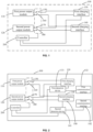
FIG. 1 which is a schematic diagram of a charging device according to an example of the present application, acharging device 100 includes a firstpower output module 110, a secondpower output module 120, afirst charging interface 130, asecond charging interface 140, and acontroller 200. - The
charging device 100 refers to a device for charging a battery pack of a power tool. The power tool may include, but is not limited to, a string trimmer, a blower, a pruner, a chainsaw, a lawn mower, an angle grinder, and an electric drill. Of course, the power tool may also include another type of tool, which is not limited in the examples of the present application. The battery pack includes a housing, the housing at least partially forms an outer surface of the battery pack and is used for accommodating at least a cell group, and the cell group includes multiple cells which are electrically connected to form the cell group. The housing is further formed with a plugging interface for connecting the battery pack to the power tool, and the battery pack can be connected to the power tool along a plugging direction. As a power source for the power tool, the battery pack may be used for supplying power to the power tool. Exemplarily, thecharging device 100 may be a charger or an adapter, which is not limited in the examples of the present application. - A
first switch 150 is coupled between the firstpower output module 110 and thefirst charging interface 130. The firstpower output module 110 refers to a module outputting power, and thefirst charging interface 130 refers to an interface for supplying power of thecharging device 100 to the battery pack of the power tool. In the case where thefirst switch 150 is on, the firstpower output module 110 supplies power to thefirst charging interface 130; and in the case where thefirst switch 150 is off, the firstpower output module 110 does not supply power to thefirst charging interface 130. - A
second switch 160 is coupled between the firstpower output module 110 and thesecond charging interface 140. Thesecond charging interface 140 refers to an interface for supplying the power of thecharging device 100 to the battery pack of the power tool. In the case where thesecond switch 160 is on, the firstpower output module 110 supplies power to thesecond charging interface 140; and in the case where thesecond switch 160 is off, the firstpower output module 110 does not supply power to thesecond charging interface 140. - In a possible example, the
first switch 150 and thesecond switch 160 are single pole, single throw switches, that is, an end of thefirst switch 150 is coupled to the firstpower output module 110 and the other end of thefirst switch 150 is coupled to thefirst charging interface 130. An end of thesecond switch 160 is coupled to the firstpower output module 110 and the other end of thesecond switch 160 is coupled to thesecond charging interface 140. - In a possible example, the first switch and the second switch may be provided as one switch, where the switch may be used for making the first power output module supply power to the first charging interface or making the first power output module supply power to the second charging interface or making the first power output module not supply power to the first charging interface and the second charging interface. Exemplarily, the switch may be a single pole, triple throw switch, or the switch may be a two-way metal-oxide-semiconductor field-effect transistor (MOSFET) switch, or the switch may be a two-way single pole, double throw switch. The type of the switch is not limited in the examples of the present application, and the switch may be replaced with any type of switch capable of implementing the preceding functions.
- A
third switch 170 is coupled between the secondpower output module 120 and thefirst charging interface 130. The secondpower output module 120 refers to a module outputting power. The power outputted by the firstpower output module 110 may or may not be consistent with the power outputted by the secondpower output module 120, which may be set by a technician according to actual requirements. In the case where thethird switch 170 is on, the secondpower output module 120 supplies power to thefirst charging interface 130; and in the case where thethird switch 170 is off, the secondpower output module 120 does not supply power to thefirst charging interface 130. - A
fourth switch 180 is coupled between the secondpower output module 120 and thesecond charging interface 140. In the case where thefourth switch 180 is on, the secondpower output module 120 supplies power to thesecond charging interface 140; and in the case where thefourth switch 180 is off, the secondpower output module 120 does not supply power to thesecond charging interface 140. - In a possible example, the
third switch 170 and thefourth switch 180 are single pole, single throw switches, that is, an end of thethird switch 170 is coupled to the secondpower output module 120 and the other end of thethird switch 170 is coupled to thefirst charging interface 130; and an end of thefourth switch 180 is coupled to the secondpower output module 120 and the other end of thefourth switch 180 is coupled to thesecond charging interface 140. - In a possible example, the third switch and the fourth switch may be provided as one switch, where the switch may be used for making the second power output module supply power to the first charging interface or making the second power output module supply power to the second charging interface or making the second power output module not supply power to the first charging interface and the second charging interface. Exemplarily, the switch may be a single pole, triple throw switch, or the switch may be a two-way MOSFET switch, or the switch may be a two-way single pole, double throw switch. The type of the switch is not limited in the examples of the present application, and the switch may be replaced with any type of switch capable of implementing the preceding functions. As shown in
FIG. 2, FIG. 2 is a schematic diagram of switches according to an example of the present application. InFIG. 2 , thecharging device 100 uses single pole, triple throw switches. - The
controller 200 is used for controlling thefirst switch 150, thesecond switch 160, thethird switch 170 and thefourth switch 180 to be turned on or off. - In a possible example, the
controller 200 acquires a load state of thefirst charging interface 130 and a load state of thesecond charging interface 140 and controls thefirst switch 150, thesecond switch 160, thethird switch 170 and thefourth switch 180 to be turned on or off, where the load state of thefirst charging interface 130 is used for indicating whether thefirst charging interface 130 is connected to a first battery pack. The load state of thefirst charging interface 130 is also used for indicating a state of charge of the first battery pack when thefirst charging interface 130 is connected to the first battery pack, and the load state of thesecond charging interface 140 is used for indicating whether thesecond charging interface 140 is connected to a second battery pack and a state of charge of the second battery pack. Thecontroller 200 controls, according to the load state of thefirst charging interface 130 and the load state of thesecond charging interface 140, the first switch, the second switch, the third switch and the fourth switch to be turned on or off so that the power supply output of thecharging device 100 to the battery pack is more in line with the charging requirements of the battery pack, thereby improving the charging efficiency of thecharging device 100. - In the examples of the present application, the charging
device 100 includes thefirst charging interface 130 and thesecond charging interface 140, thefirst switch 150 is coupled between the firstpower output module 110 and thefirst charging interface 130, thesecond switch 160 is coupled between the firstpower output module 110 and thesecond charging interface 140, thethird switch 170 is coupled between the secondpower output module 120 and thefirst charging interface 130, thefourth switch 180 is coupled between the secondpower output module 120 and thesecond charging interface 140, and the switches are controlled by thecontroller 200. In this manner, the output capacity and parallel function of thecharging device 100 are increased so that the battery pack can be charged fast at high power. - To sum up, in the technical solutions provided in the examples of the present application, two charging interfaces are provided in the
charging device 100 so that two battery packs can be charged at the same time, thereby improving the charging efficiency. - In addition, the
first switch 150 is coupled between the firstpower output module 110 and thefirst charging interface 130, thesecond switch 160 is coupled between the firstpower output module 110 and thesecond charging interface 140, thethird switch 170 is coupled between the secondpower output module 120 and thefirst charging interface 130, thefourth switch 180 is coupled between the secondpower output module 120 and thesecond charging interface 140, and the switches are controlled by thecontroller 200 so that thecharging device 100 can control the switches to be turned on or off according to an actual application situation, thereby improving the charging efficiency and achieving high flexibility. - In an illustrative example, as shown in
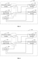
FIG. 3 , the chargingdevice 100 further includes afirst detection device 131 and asecond detection device 141. Thefirst detection device 131 is used for determining the load state of thefirst charging interface 130, where the load state of thefirst charging interface 130 is used for indicating whether thefirst charging interface 130 is connected to the first battery pack and the state of charge of the first battery pack. The state of charge of the first battery pack is used for indicating the current charge of the first battery pack. - The
first detection device 131 is coupled to thefirst charging interface 130. Thefirst detection device 131 may determine whether thefirst charging interface 130 is connected to the first battery pack by detecting whether a voltage exists across thefirst charging interface 130. In a possible example, to more accurately detect whether thefirst charging interface 130 is connected to the first battery pack, and thefirst detection device 131 is also coupled to afirst communication interface 132 on thecharging device 100. Thefirst detection device 131 determines a voltage across the first charging interface and a voltage across thefirst communication interface 132 at the same time and determines. Based on the voltage across thefirst charging interface 130 and the voltage across thefirst communication interface 132, determine whether thefirst charging interface 130 is connected to the first battery pack. In the case where thefirst detection device 131 determines that a voltage exists across thefirst charging interface 130 and a voltage exists across thefirst communication interface 132, thefirst detection device 131 determines that thefirst charging interface 130 is connected to the first battery pack. In the case where thefirst detection device 131 determines that no voltage exists across thefirst charging interface 130 and no voltage exists across thefirst communication interface 132, thefirst detection device 131 determines that thefirst charging interface 130 is not connected to the first battery pack. In the case where thefirst detection device 131 determines that a voltage exists across thefirst charging interface 130 and no voltage exists across thefirst communication interface 132, thefirst detection device 131 determines that thefirst charging interface 130 is not connected to the first battery pack. In the case where thefirst detection device 131 determines that no voltage exists across thefirst charging interface 130 and a voltage exists across thefirst communication interface 132, thefirst detection device 131 determines that thefirst charging interface 130 is not connected to the first battery pack. Exemplarily, thefirst charging interface 130 includes a positive interface and a negative interface, and the first battery pack includes a positive terminal and a negative terminal. When the positive interface of thefirst charging interface 130 is coupled to the positive terminal of the first battery pack and the negative interface of thefirst charging interface 130 is coupled to the negative terminal of the first battery pack, thefirst charging interface 130 may supply power to the first battery pack. - The
first communication interface 132 is used for thecharging device 100 to communicate with the first battery pack. The first battery pack further includes a communication port. When thefirst communication interface 132 of thecharging device 100 is coupled to the communication port of the first battery pack, the first battery pack may communicate with the chargingdevice 100. - In a possible example, the first battery pack sends its state of charge to the
charging device 100 through the communication port. In a example, the chargingdevice 100 automatically detects the charge of the first battery pack to obtain the state of charge of the first battery pack. - The
second detection device 141 is used for determining the load state of thesecond charging interface 140, where the load state of thesecond charging interface 140 is used for indicating whether thesecond charging interface 140 is connected to the second battery pack and the state of charge of the second battery pack. The state of charge of the second battery pack is used for indicating the current charge of the second battery pack. - The
second detection device 141 is coupled to thesecond charging interface 140. Thesecond detection device 141 may determine whether thesecond charging interface 140 is connected to the second battery pack by detecting whether a voltage exists across thesecond charging interface 140. In a possible example, to more accurately detect whether thesecond charging interface 140 is connected to the second battery pack, thesecond detection device 141 is also coupled to asecond communication interface 142 on thecharging device 100, and thesecond detection device 141 determines a voltage across thesecond charging interface 140 and a voltage across thesecond communication interface 142 at the same time and determines, based on the voltage across thesecond charging interface 140 and the voltage across thesecond communication interface 142, whether thesecond charging interface 140 is connected to the second battery pack. In the case where thesecond detection device 141 determines that a voltage exists across thesecond charging interface 140 and a voltage exists across thesecond communication interface 142, thesecond detection device 141 determines that thesecond charging interface 140 is connected to the second battery pack. In the case where thesecond detection device 141 determines that no voltage exists across thesecond charging interface 140 and no voltage exists across thesecond communication interface 142, thesecond detection device 141 determines that thesecond charging interface 140 is not connected to the second battery pack. In the case where thesecond detection device 141 determines that a voltage exists across thesecond charging interface 140 and no voltage exists across thesecond communication interface 142, thesecond detection device 141 determines that thesecond charging interface 140 is not connected to the second battery pack. In the case where thesecond detection device 141 determines that no voltage exists across the second charging interface and a voltage exists across thesecond communication interface 142, thesecond detection device 141 determines that thesecond charging interface 140 is not connected to the second battery pack. Exemplarily, thesecond charging interface 140 includes a positive interface and a negative interface, and the second battery pack includes a positive terminal and a negative terminal. When the positive interface of thesecond charging interface 140 is coupled to the positive terminal of the second battery pack and the negative interface of thesecond charging interface 140 is coupled to the negative terminal of the second battery pack, the second charging interface may supply power to the second battery pack. - The
second communication interface 142 is used for thecharging device 100 to communicate with the second battery pack. The second battery pack further includes a communication port. When thesecond communication interface 142 of thecharging device 100 is coupled to the communication port of the second battery pack, the second battery pack may communicate with the chargingdevice 100. - In a possible example, the second battery pack sends its state of charge to the
charging device 100 through the communication port; or thecharging device 100 automatically detects the charge of the second battery pack to obtain the state of charge of the second battery pack. - The
controller 200 is configured to control thefirst switch 150, thesecond switch 160, thethird switch 170 and thefourth switch 180 to be turned on or off based on the load state of thefirst charging interface 130 and the load state of thesecond charging interface 140. - The
controller 200 controls thefirst switch 150, thesecond switch 160, thethird switch 170 and thefourth switch 180 to be turned on or off according to the load state of thefirst charging interface 130 and the load state of thesecond charging interface 140, so that the power supply output of thecharging device 100 to the battery pack is more in line with the charging requirements of the battery pack, thereby improving the charging efficiency of thecharging device 100. - In a possible example, the
first detection device 131 is used for determining that the load state of thefirst charging interface 130 is that thefirst charging interface 130 is connected to the first battery pack and the first battery pack is not fully charged. Thesecond detection device 141 is used for determining that the load state of thesecond charging interface 140 is that thesecond charging interface 140 is not connected to the second battery pack. Thecontroller 200 is used for turning on thefirst switch 150 and thethird switch 170 and turning off thesecond switch 160 and thefourth switch 180. - In this case, the charging
device 100 supplies power to the first battery pack through the firstpower output module 110 and the secondpower output module 120 at the same time, shortening the time for charging the first battery pack and improving the charging efficiency. At the same time, thesecond switch 160 and thefourth switch 180 are turned off so that the firstpower output module 110 and/or the secondpower output module 120 do not supply power to the second charging interface, thereby avoiding energy waste. - As shown in
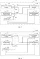
FIG. 4, FIG. 4 is a schematic diagram of states of switches according to an example of the present application. Thesecond charging interface 140 is not connected to the second battery pack, and the firstpower output module 110 and the secondpower output module 120 supply power to the first battery pack. - Exemplarily, as shown in
FIG. 5 , using an example in which the first switch and the second switch are implemented as a first single pole, triple throw switch and the third switch and the fourth switch are implemented as a second single pole, triple throw switch, the first single pole, triple throw switch and the second single pole, triple throw switch are set to be in the states shown inFIG. 4 so that the firstpower output module 110 and the secondpower output module 120 charge the first battery pack at the same time. - It is to be noted that, in the example of the present application, only an example in which the
first charging interface 130 is connected to the first battery pack and thesecond charging interface 140 is not connected to the second battery pack is used for description, and a charging control logic in the case where thefirst charging interface 130 is not connected to the first battery pack and thesecond charging interface 140 is connected to the second battery pack is similar to that in the preceding case. That is, in the case where thefirst charging interface 130 is not connected to the first battery pack, thesecond charging interface 140 is connected to the second battery pack, and the second battery pack is not fully charged, thecontroller 200 turns on thesecond switch 160 and thefourth switch 180 and turns off thefirst switch 150 and thethird switch 170. - In a possible example, the
first detection device 131 is used for determining that the load state of thefirst charging interface 130 is that thefirst charging interface 130 is connected to the first battery pack and the first battery pack is not fully charged. Thesecond detection device 141 is used for determining that the load state of thesecond charging interface 140 is that thesecond charging interface 140 is connected to the second battery pack and the second battery pack is fully charged. Thecontroller 200 is used for turning on thefirst switch 150 and thethird switch 170 and turning off thesecond switch 160 and thefourth switch 180. - In this case, the charging
device 100 supplies power to the first battery pack through the firstpower output module 110 and the secondpower output module 120 at the same time, shortening the time for charging the first battery pack and improving the charging efficiency. At the same time, in the case where the second battery pack is fully charged, thesecond switch 160 and thefourth switch 180 are turned off so that the firstpower output module 110 and/or the secondpower output module 120 do not supply power to the second charging interface, thereby avoiding energy waste. - It is to be noted that, in the example of the present application, only an example in which the first battery pack is not fully charged and the second battery pack is fully charged is used for description, and a charging control logic in the case where the first battery pack is fully charged and the second battery pack is not fully charged is similar to that in the preceding case. That is, in the case where the
first charging interface 130 is connected to the first battery pack, the first battery pack is fully charged, the second charging interface is connected to the second battery pack, and the second battery pack is not fully charged, thecontroller 200 turns on thesecond switch 160 and thefourth switch 180 and turns off thefirst switch 150 and thethird switch 170. - When no battery pack exists or when a battery pack exists but the battery pack is fully charged, the corresponding power output module is disconnected from the charging interface, and the idle power output module is connected in parallel to charge the battery pack that needs to be charged.
- In a possible example, the
first detection device 131 is used for determining that the load state of thefirst charging interface 130 is that thefirst charging interface 130 is not connected to the first battery pack. Thesecond detection device 141 is used for determining that the load state of thesecond charging interface 140 is that thesecond charging interface 140 is not connected to the second battery pack. Thecontroller 200 is used for turning off the first switch, the second switch, the third switch and the fourth switch. - In the case where neither the
first charging interface 130 nor thesecond charging interface 140 is connected to the battery pack, the chargingdevice 100 turns off thefirst switch 150, the second switch, thethird switch 170 and thefourth switch 180 so that the firstpower output module 110 and the secondpower output module 120 do not supply power to the outside, thereby avoiding energy waste. - Exemplarily, as shown in
FIG. 6 , using an example in which the first switch and the second switch are implemented as a first single pole, triple throw switch and the third switch and the fourth switch are implemented as a second single pole, triple throw switch, the first single pole, triple throw switch and the second single pole, triple throw switch are set to be in the null connection states shown inFIG. 6 so that the firstpower output module 110 and the secondpower output module 120 do not supply power to the charging interfaces. - In a possible example, the
first detection device 131 is used for determining that the load state of thefirst charging interface 130 is that thefirst charging interface 130 is connected to the first battery pack and the first battery pack is fully charged. Thesecond detection device 141 is used for determining that the load state of thesecond charging interface 140 is that thesecond charging interface 140 is connected to the second battery pack and the second battery pack is fully charged. Thecontroller 200 is used for turning off thefirst switch 150, thesecond switch 160, thethird switch 170 and thefourth switch 180. - In the case where the
first charging interface 130 is connected to the first battery pack, the first battery pack is fully charged, thesecond charging interface 140 is connected to the second battery pack, and the second battery pack is fully charged, the chargingdevice 100 turns off thefirst switch 150, thesecond switch 160, thethird switch 170 and thefourth switch 180 so that the firstpower output module 110 and the secondpower output module 120 do not supply power to the outside, thereby avoiding energy waste. - In a possible example, the
first detection device 131 is used for determining that the load state of thefirst charging interface 130 is that thefirst charging interface 130 is connected to the first battery pack and the first battery pack is not fully charged. Thesecond detection device 141 is used for determining that the load state of thesecond charging interface 140 is that thesecond charging interface 140 is connected to the second battery pack and the second battery pack is not fully charged. Thecontroller 200 is used for turning on thefirst switch 150 and the fourth 180 switch and turning off thesecond switch 160 and thethird switch 170. - In the case where neither the first battery pack nor the second battery pack is fully charged, the first
power output module 110 supplies power to the first battery pack and the secondpower output module 120 supplies power to the second battery pack, thereby improving the charging efficiency. - When both the
first charging interface 130 and thesecond charging interface 140 are connected to the battery packs and neither of the battery packs is fully charged, each of the firstpower output module 110 and the secondpower output module 120 independently charges a respective battery pack. - As shown in
FIG. 7, FIG. 7 is a schematic diagram of states of switches according to another example of the present application. When both thefirst charging interface 130 and thesecond charging interface 140 are connected to the battery packs and neither of the battery packs is fully charged, each of the firstpower output module 110 and the secondpower output module 120 independently supplies power to a respective charging interface. - Exemplarily, as shown in
FIG. 8 , using an example in which the first switch and the second switch are implemented as a first single pole, triple throw switch and the third switch and the fourth switch are implemented as a second single pole, triple throw switch, the first single pole, triple throw switch and the second single pole, triple throw switch are set to be in the states shown inFIG. 8 so that each of the firstpower output module 110 and the secondpower output module 120 independently supplies power to its respective charge interface. - Referring to
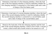
FIG. 9, FIG. 9 is a flowchart of a control method for a charging device according to an example of the present application. The control method is not covered by the scope of the appended claims but is included in this description for illustrative purposes. The charging device includes a first power output module, a second power output module, a first charging interface, a second charging interface, and a controller. A first switch is coupled between the first power output module and the first charging interface, a second switch is coupled between the first power output module and the second charging interface, a third switch is coupled between the second power output module and the first charging interface, and a fourth switch is coupled between the second power output module and the second charging interface. The method may include the steps described below. - In
step 801, a load state of the first charging interface is determined, where the load state of the first charging interface is used for indicating whether the first charging interface is connected to a first battery pack and a state of charge of the first battery pack. - In step 802, a load state of the second charging interface is determined, where the load state of the second charging interface is used for indicating whether the second charging interface is connected to a second battery pack and a state of charge of the second battery pack.
- In
step 803, based on the load state of the first charging interface and the load state of the second charging interface, the first switch, the second switch, the third switch and the fourth switch are controlled to be turned on or off. - Step 801 and step 802 may be performed simultaneously; or step 801 may be performed before step 802 is performed; or step 802 may be performed before
step 801 is performed, which is not limited in the examples of the present application. - In an illustrative example,
step 801 includes determining that the load state of the first charging interface is that the first charging interface is connected to the first battery pack and the first battery pack is not fully charged. - Step 802 includes determining that the load state of the second charging interface is that the second charging interface is not connected to the second battery pack.
- Step 803 includes turning on the first switch and the third switch and turning off the second switch and the fourth switch.
- In an illustrative example,
step 801 includes determining that the load state of the first charging interface is that the first charging interface is connected to the first battery pack and the first battery pack is not fully charged. - Step 802 includes determining that the load state of the second charging interface is that the second charging interface is connected to the second battery pack and the second battery pack is fully charged.
- Step 803 includes turning on the first switch and the third switch and turning off the second switch and the fourth switch.
- In an illustrative example,
step 801 includes determining that the load state of the first charging interface is that the first charging interface is not connected to the first battery pack. - Step 802 includes determining that the load state of the second charging interface is that the second charging interface is not connected to the second battery pack.
- Step 803 includes turning off the first switch, the second switch, the third switch and the fourth switch.
- In an illustrative example,
step 801 includes determining that the load state of the first charging interface is that the first charging interface is connected to the first battery pack and the first battery pack is fully charged. - Step 802 includes determining that the load state of the second charging interface is that the second charging interface is connected to the second battery pack and the second battery pack is fully charged.
- Step 803 includes turning off the first switch, the second switch, the third switch and the fourth switch.
- In an illustrative example,
step 801 includes determining that the load state of the first charging interface is that the first charging interface is connected to the first battery pack and the first battery pack is not fully charged. - Step 802 includes determining that the load state of the second charging interface is that the second charging interface is connected to the second battery pack and the second battery pack is not fully charged.
- Step 803 includes turning on the first switch and the fourth switch and turning off the second switch and the third switch.
- To sum up, in the technical solutions provided in the examples of the present application, two charging interfaces are provided in the charging device so that two battery packs can be charged at the same time, thereby improving charging efficiency.
- In addition, the first switch is coupled between the first power output module and the first charging interface, the second switch is coupled between the first power output module and the second charging interface, the third switch is coupled between the second power output module and the first charging interface, the fourth switch is coupled between the second power output module and the second charging interface, and the switches are controlled by the controller based on the load states of the charging interfaces so that the charging device can control the switches to be turned on or off according to an actual application situation, thereby improving the charging efficiency and achieving high flexibility.
- It is to be noted that the method example and the product example provided in the preceding examples belong to the same concept, and for the specific implementation process of the method example, see the product example, and details are not repeated here.
- It is to be noted that, in the examples of the present application, only an example in which the charging device includes two charging interfaces is used for description. In other possible examples, the charging device may include three or more charging interfaces, which is not limited in the examples of the present application.
- It is to be understood that "multiple" mentioned herein means two or more. "And/or" describes an association relationship between associated objects and indicates that three relationships may exist. For example, A and/or B may indicate the following three cases: A exists alone; A and B exist at the same time; and B exists alone. The character "/" generally indicates an "or" relationship between associated objects before and after the character. In addition, the numbering of the steps described herein only exemplarily shows a possible execution sequence of the steps. In some other examples, the preceding steps may not be executed according to the numbering, for example, two steps with different numbers are performed at the same time, or two steps with different numbers are performed in an order reverse to the order shown in the figure, which is not limited in the examples of the present application.
- Those of ordinary skill in the art can understand that all or part of the steps for implementing the preceding examples may be performed by hardware or may be performed by relevant hardware instructed by a program, where the program may be stored in a computer-readable storage medium. The preceding storage medium may be a read-only memory, a magnetic disk, an optical disk or the like. Since the control method is not covered by the scope of the appended claims, these programs implementations are also not covered by the scope of the onvention. Both (method, program) are included in this description for illustrative purposes.
- The above are only exemplary examples of the present application and not intended to limit the present application. The scope of the invention is only defined by the appended claims.
Claims (15)
- A charging device (100), comprising:a first charging interface (130) connectable to a first battery pack for charging the first battery pack;a second charging interface (140) connectable to a second battery pack for charging the second battery pack;a first power output module (110) connected to the first charging interface to charge the first battery pack;a second power output module (120) connected to the second charging interface to charge the second battery pack; anda controller (200) connected to at least the first charging interface and the second charging interface; wherein the controller is configured to:characterized in that
when the first battery pack is fully charged or not connected to the first charging interface, control the first power output module and the second power output module to be electrically connected to the second charging interface to charge the second battery pack;the first battery pack is a battery pack of a power tooland that the second battery pack is a battery pack of a power tool. - The charging device of claim 1, wherein a first switch (150) is coupled between the first power output module and the first charging interface, a second switch (160) is coupled between the first power output module and the second charging interface, a third switch (170) is coupled between the second power output module and the first charging interface, a fourth switch (180) is coupled between the second power output module and the second charging interface, and the controller is configured to control the first switch, the second switch, the third switch and the fourth switch to be turned on or off.
- The charging device of claim 1, further comprising a first detection device (131) for determining a load state of the first charging interface and a second detection device (141) for determining a load state of the second charging interface.
- The charging device of claim 3, wherein the load state of the first charging interface is used for indicating whether the first charging interface is connected to the first battery pack and a state of charge of the first battery pack, and the load state of the second charging interface is used for indicating whether the second charging interface is connected to the second battery pack and a state of charge of the second battery pack.
- The charging device of claim 4, wherein a first switch (150) is coupled between the first power output module and the first charging interface, a second switch (160) is coupled between the first power output module and the second charging interface, a third switch (170) is coupled between the second power output module and the first charging interface, a fourth switch (180) is coupled between the second power output module and the second charging interface, and the controller is configured to the first switch, the second switch, the third switch and the fourth switch to be turned on or off based on the load state of the first charging interface and the load state of the second charging interface.
- The charging device of claim 5, wherein the controller is configured to turn off the first switch and the third switch when the load state of the first charging interface determined by the first detection device is that the first charging interface is not connected to the first battery pack or the first battery pack is fully charged.
- The charging device of claim 5, wherein the controller is configured to turn off the second switch and the fourth switch when the load state of the second charging interface determined by the second detection device is that the second charging interface is not connected to the second battery pack or the second battery pack is fully charged.
- The charging device of claim 5, wherein when the load state of the first charging interface is that the first charging interface is connected to the first battery pack and the first battery pack is not fully charged, and the load state of the second charging interface is that the second charging interface is not connected to the second battery pack, the controller is configured to control the first switch and the third switch to be turned on and control the second switch and the fourth switch to be turned off.
- The charging device of claim 5, wherein when the load state of the first charging interface is that the first charging interface is connected to the first battery pack and the first battery pack is not fully charged, and the load state of the second charging interface is that the second charging interface is connected to the second battery pack and the second battery pack is fully charged, the controller is configured to control the first switch and the third switch to be turned on and control the second switch and the fourth switch to be turned off.
- The charging device of claim 5, wherein when the load state of the first charging interface is that the first charging interface is not connected to the first battery pack, and the load state of the second charging interface is that the second charging interface is not connected to the second battery pack, the controller is configured to control the first switch, the second switch, the third switch and the fourth switch to be turned off.
- The charging device of claim 5, wherein when the load state of the first charging interface is that the first charging interface is connected to the first battery pack and the first battery pack is fully charged, and the load state of the second charging interface is that the second charging interface is connected to the second battery pack and the second battery pack is fully charged, the controller is configured to control the first switch, the second switch, the third switch and the fourth switch to be turned off.
- The charging device of claim 5, wherein when the load state of the first charging interface is that the first charging interface is connected to the first battery pack and the first battery pack is not fully charged, and the load state of the second charging interface is that the second charging interface is connected to the second battery pack and the second battery pack is not fully charged, the controller is configured to control the first switch and the fourth switch to be turned on and control the second switch and the third switch to be turned off.
- The charging device of claim 5, wherein when the load state of the first charging interface is that the first charging interface is connected to the first battery pack and the first battery pack is not fully charged, and the load state of the second charging interface is that the second charging interface is connected to the second battery pack and the second battery pack is not fully charged, the controller is configured to control the second switch and the third switch to be turned on and control the first switch and the fourth switch to be turned off.
- The charging device of claim 3, wherein the load state comprises at least the state of charge of the first battery pack or the second battery pack.
- The charging device of claim 14, further comprising a first communication interface (132) and a second communication interface (142); wherein the first communication interface is connected to the first battery pack to acquire at least the state of charge of the first battery pack, and the second communication interface is connected to the second battery pack to acquire at least the state of charge of the second battery pack.
Applications Claiming Priority (1)
| Application Number | Priority Date | Filing Date | Title |
|---|---|---|---|
| CN202111268864 | 2021-10-29 |
Publications (2)
| Publication Number | Publication Date |
|---|---|
| EP4178068A1 EP4178068A1 (en) | 2023-05-10 |
| EP4178068B1 true EP4178068B1 (en) | 2024-04-17 |
Family
ID=83232841
Family Applications (1)
| Application Number | Title | Priority Date | Filing Date |
|---|---|---|---|
| EP22194252.7A Active EP4178068B1 (en) | 2021-10-29 | 2022-09-07 | Charging device |
Country Status (4)
| Country | Link |
|---|---|
| US (1) | US20230138183A1 (en) |
| EP (1) | EP4178068B1 (en) |
| CN (1) | CN116073465A (en) |
| AU (1) | AU2022228178A1 (en) |
Family Cites Families (4)
| Publication number | Priority date | Publication date | Assignee | Title |
|---|---|---|---|---|
| JP4855444B2 (en) * | 2008-06-25 | 2012-01-18 | レノボ・シンガポール・プライベート・リミテッド | Charging control system and control method |
| CN106786887B (en) * | 2016-12-23 | 2019-08-23 | 捷开通讯(深圳)有限公司 | A kind of charge control system |
| DE102018212740A1 (en) * | 2018-07-31 | 2020-02-06 | Ads-Tec Gmbh | Charging station for electric cars |
| EP3890135A1 (en) * | 2020-03-30 | 2021-10-06 | ABB Power Grids Switzerland AG | Sst system with multiple lvdc outputs |
-
2022
- 2022-09-07 EP EP22194252.7A patent/EP4178068B1/en active Active
- 2022-09-08 US US17/940,048 patent/US20230138183A1/en active Pending
- 2022-09-09 AU AU2022228178A patent/AU2022228178A1/en active Pending
- 2022-09-23 CN CN202211161944.8A patent/CN116073465A/en active Pending
Also Published As
| Publication number | Publication date |
|---|---|
| AU2022228178A1 (en) | 2023-05-18 |
| EP4178068A1 (en) | 2023-05-10 |
| US20230138183A1 (en) | 2023-05-04 |
| CN116073465A (en) | 2023-05-05 |
Similar Documents
| Publication | Publication Date | Title |
|---|---|---|
| EP3288147B1 (en) | Electric tool and control method therefor | |
| CN102113192B (en) | Multipurpose portable storage and supply system | |
| KR102247394B1 (en) | Battery Pack and Battery Driving Apparatus and Method Using Thereof | |
| CN102545291B (en) | Solar power storage system and solar power supply system | |
| US20070236975A1 (en) | Method and apparatus for balancing energy between portable devices | |
| CN103503273A (en) | Battery charger and power supply apparatus | |
| WO2018175983A1 (en) | Terminal configuration for a battery pack | |
| JP7039773B2 (en) | Power system including battery pack | |
| JP4488381B2 (en) | Battery pack system | |
| KR102200551B1 (en) | Battery back | |
| CN103227487B (en) | Fuel cell/lithium ion battery hybrid power energy management system used for electric bicycle | |
| CN114448010A (en) | Charging and discharging control system and method and battery pack | |
| EP3883086A1 (en) | Electric tool power supply having vehicle starting function | |
| EP4178068B1 (en) | Charging device | |
| CN210608615U (en) | Secondary protection circuit for charging and discharging hardware of lithium ion battery | |
| CN206977128U (en) | The battery protection system of new energy | |
| CA3180316A1 (en) | Charging device and control method therefor | |
| CN201134695Y (en) | Management circuit for lithium battery charging | |
| CN111884292A (en) | Intelligent charger capable of automatically identifying external adapter and charging method | |
| CN104143663A (en) | High-current lithium ion battery pack with self-protective function and expansibility | |
| CN212343374U (en) | Protection circuit of variable voltage lithium cell group | |
| CN218805248U (en) | Seamless quick-change lithium ion power supply system suitable for AGV | |
| US20220190620A1 (en) | Battery pack | |
| CN110429570B (en) | Multi-functional protection circuit of multisection lithium cell | |
| CN216720949U (en) | Charge-discharge protection device and starting power supply equipment |
Legal Events
| Date | Code | Title | Description |
|---|---|---|---|
| PUAI | Public reference made under article 153(3) epc to a published international application that has entered the european phase |
Free format text: ORIGINAL CODE: 0009012 |
|
| STAA | Information on the status of an ep patent application or granted ep patent |
Free format text: STATUS: THE APPLICATION HAS BEEN PUBLISHED |
|
| AK | Designated contracting states |
Kind code of ref document: A1 Designated state(s): AL AT BE BG CH CY CZ DE DK EE ES FI FR GB GR HR HU IE IS IT LI LT LU LV MC MK MT NL NO PL PT RO RS SE SI SK SM TR |
|
| STAA | Information on the status of an ep patent application or granted ep patent |
Free format text: STATUS: REQUEST FOR EXAMINATION WAS MADE |
|
| 17P | Request for examination filed |
Effective date: 20231011 |
|
| RBV | Designated contracting states (corrected) |
Designated state(s): AL AT BE BG CH CY CZ DE DK EE ES FI FR GB GR HR HU IE IS IT LI LT LU LV MC MK MT NL NO PL PT RO RS SE SI SK SM TR |
|
| GRAP | Despatch of communication of intention to grant a patent |
Free format text: ORIGINAL CODE: EPIDOSNIGR1 |
|
| STAA | Information on the status of an ep patent application or granted ep patent |
Free format text: STATUS: GRANT OF PATENT IS INTENDED |
|
| GRAS | Grant fee paid |
Free format text: ORIGINAL CODE: EPIDOSNIGR3 |
|
| INTG | Intention to grant announced |
Effective date: 20240216 |
|
| GRAA | (expected) grant |
Free format text: ORIGINAL CODE: 0009210 |
|
| STAA | Information on the status of an ep patent application or granted ep patent |
Free format text: STATUS: THE PATENT HAS BEEN GRANTED |
|
| AK | Designated contracting states |
Kind code of ref document: B1 Designated state(s): AL AT BE BG CH CY CZ DE DK EE ES FI FR GB GR HR HU IE IS IT LI LT LU LV MC MK MT NL NO PL PT RO RS SE SI SK SM TR |
|
| REG | Reference to a national code |
Ref country code: GB Ref legal event code: FG4D |
|
| REG | Reference to a national code |
Ref country code: CH Ref legal event code: EP |
|
| REG | Reference to a national code |
Ref country code: DE Ref legal event code: R096 Ref document number: 602022002913 Country of ref document: DE |