EP4176619B1 - Migration of user equipment in an integrated access and backhaul network - Google Patents
Migration of user equipment in an integrated access and backhaul network Download PDFInfo
- Publication number
- EP4176619B1 EP4176619B1 EP20737006.5A EP20737006A EP4176619B1 EP 4176619 B1 EP4176619 B1 EP 4176619B1 EP 20737006 A EP20737006 A EP 20737006A EP 4176619 B1 EP4176619 B1 EP 4176619B1
- Authority
- EP
- European Patent Office
- Prior art keywords
- iab node
- node
- ues
- iab
- served
- Prior art date
- Legal status (The legal status is an assumption and is not a legal conclusion. Google has not performed a legal analysis and makes no representation as to the accuracy of the status listed.)
- Active
Links
- 230000005012 migration Effects 0.000 title claims description 33
- 238000013508 migration Methods 0.000 title claims description 33
- 238000000034 method Methods 0.000 claims description 72
- 238000012545 processing Methods 0.000 claims description 58
- 238000004590 computer program Methods 0.000 claims description 55
- 230000004044 response Effects 0.000 claims description 8
- 230000000977 initiatory effect Effects 0.000 claims description 6
- 238000012423 maintenance Methods 0.000 claims description 6
- 230000005540 biological transmission Effects 0.000 description 34
- 238000004891 communication Methods 0.000 description 28
- 238000005259 measurement Methods 0.000 description 15
- 238000010586 diagram Methods 0.000 description 10
- 230000011664 signaling Effects 0.000 description 9
- 230000007246 mechanism Effects 0.000 description 7
- 230000001960 triggered effect Effects 0.000 description 7
- 230000003287 optical effect Effects 0.000 description 5
- 238000007726 management method Methods 0.000 description 3
- 230000002085 persistent effect Effects 0.000 description 3
- 239000007787 solid Substances 0.000 description 3
- 230000004048 modification Effects 0.000 description 2
- 238000012986 modification Methods 0.000 description 2
- 239000013307 optical fiber Substances 0.000 description 2
- 238000002360 preparation method Methods 0.000 description 2
- 230000008569 process Effects 0.000 description 2
- 230000001133 acceleration Effects 0.000 description 1
- 230000001427 coherent effect Effects 0.000 description 1
- 125000004122 cyclic group Chemical group 0.000 description 1
- 238000000280 densification Methods 0.000 description 1
- 230000001419 dependent effect Effects 0.000 description 1
- 230000006870 function Effects 0.000 description 1
- 230000006872 improvement Effects 0.000 description 1
- 230000010354 integration Effects 0.000 description 1
- 238000012544 monitoring process Methods 0.000 description 1
- 238000013468 resource allocation Methods 0.000 description 1
- 238000012384 transportation and delivery Methods 0.000 description 1
Images


Classifications
-
- H—ELECTRICITY
- H04—ELECTRIC COMMUNICATION TECHNIQUE
- H04W—WIRELESS COMMUNICATION NETWORKS
- H04W36/00—Hand-off or reselection arrangements
- H04W36/0005—Control or signalling for completing the hand-off
- H04W36/0055—Transmission or use of information for re-establishing the radio link
- H04W36/0072—Transmission or use of information for re-establishing the radio link of resource information of target access point
-
- H—ELECTRICITY
- H04—ELECTRIC COMMUNICATION TECHNIQUE
- H04W—WIRELESS COMMUNICATION NETWORKS
- H04W36/00—Hand-off or reselection arrangements
- H04W36/08—Reselecting an access point
-
- H—ELECTRICITY
- H04—ELECTRIC COMMUNICATION TECHNIQUE
- H04W—WIRELESS COMMUNICATION NETWORKS
- H04W84/00—Network topologies
- H04W84/02—Hierarchically pre-organised networks, e.g. paging networks, cellular networks, WLAN [Wireless Local Area Network] or WLL [Wireless Local Loop]
- H04W84/04—Large scale networks; Deep hierarchical networks
- H04W84/042—Public Land Mobile systems, e.g. cellular systems
- H04W84/045—Public Land Mobile systems, e.g. cellular systems using private Base Stations, e.g. femto Base Stations, home Node B
Definitions
- Embodiments presented herein relate to methods, a donor integrated access and backhaul (D-IAB) node, a serving integrated access and backhaul (S-IAB) node, a replacement integrated access and backhaul (R-IAB) node, computer programs, and a computer program product for migrating User Equipment (UE) from the S-IAB node to the R-IAB node.
- D-IAB donor integrated access and backhaul
- S-IAB serving integrated access and backhaul
- R-IAB replacement integrated access and backhaul
- UE User Equipment
- communications networks there may be a challenge to obtain good performance and capacity for a given communications protocol, its parameters and the physical environment in which the communications network is deployed.
- IAB Integrated Access and Backhaul
- an IAB network might comprise of a donor IAB node, parent IAB nodes, and child IAB nodes.
- the donor IAB node also acts as parent IAB node and a child IAB node might act as parent IAB node to another child IAB node.
- a child IAB node can be expected to be carried by a vehicle, such as connected and autonomous vehicle (CAV) such as aerial vehicles and ground vehicle platforms, potentially making the IAB child node portable or mobile.
- CAV connected and autonomous vehicle
- a currently deployed child IAB node may have to be replaced by another child IAB node.
- a child IAB node mounted on a CAV to extend network coverage during a mission-critical (MC) operation may have to be replaced due to its battery draining out.
- MC mission-critical
- WO 2020/067736 A1 relates to improving migration of a wireless device (a UE or an IAB node) from source IAB node to a target IAB node connected to the same donor IAB node.
- the CU of the donor IAB node Upon receiving a measurement report from a UE via the source IAB node, the CU of the donor IAB node performs context establishment procedure with the target IAB node, and then sends a message UE context modification message to the source IAB node carrying RRC connection modification message for the UE and indicating to the source IAB node to stop sending data to the UE.
- the source IAB node forwards the RRC message to the UE, and sends to the CU of the IAB donor a message indicating whether there are UL data packets that are still not sent from the source IAB node to the CU of the donor IAB node. If yes, the CU of the donor IAB node waits until the last UL packet is received before it proceeds with the rest of the handover procedure.
- 3GPP DRAFT R2-1812405 relates to IAB node migration and discloses that said migration is based on intra-gNB handover procedure which may be triggered by measurement reports received from an MT part of an IAB node, or may be triggered by a central route management entity.
- Donor gNB CU receives a measurement report form the MT of the IAB node to be migrated via source IAB node, makes a HO decision and sends a HO request to target IAB-DU.
- the target IAB-DU responds with HO acknowledge.
- the donor CU sends handover command to the MT, which detaches from the source IAB and synchronizes with the target IAB.
- Source DU sends F1 DL delivery status PDU to the donor CU, and the donor CU forwards DL packets to the target IAB node. After the handover complete message is received from the target IAB node, a route update message for the migrated IAB node is sent to all affected IAB nodes.
- US 2020/045596 A1 relates to handover acceleration in 5G, and discloses that after transmitting a handover command to a UE, a source gNB can start to send/bi-cast the DL packets to the UE and to the target gNB. The UE may receive data from both the serving gNB and the target gNB at the same time.
- the source gNB may instruct the UE to access the target gNB at a pre-allocated subframe, which may be e.g. semi-persistent resource allocation for the UE.
- the source gNB informs the target gNB about UL SN status and the pre-allocated resources.
- the target gNB directly transmits in the pre-allocated resources the PDCCS/PDSCH to the UE and receives UE UL data on the PUCCH at said resources.
- WO 2008/031258 A1 relates to improvement of HO procedure in LTE using inter-cell interference coordination.
- source eNB informs the target eNB how which resources it could reallocate from the source cell to the target cell due to handover of a UE to the target cell, wherein the source cell controller preferably selects the resources that are currently allocated for the UE.
- the target eNB accepts the offered resources and sends the answer in a response to the HO request.
- the UE is commanded to perform handover to the target cell, and once it accesses the target cell, it is scheduled in the reallocated resources.
- the resources relate to the frequency resources shared between neighbouring cells for inter-cell interference coordination.
- An object of embodiments herein is to enable seamless replacement of child IAB nodes in an IAB network.
- a method for migrating UEs from node to an R-IAB node is performed by a D-IAB node of the S-IAB node and the R-IAB node.
- the method comprises obtaining a request for replacement of the S-IAB node.
- the method comprises providing, to the S-IAB node, an indication of replacement of the S-IAB node.
- the method comprises obtaining, from the S-IAB node, scheduling information for the UEs served by the S-IAB node.
- the method comprises forwarding, to the R-IAB node, the scheduling information.
- the method comprises initiating migration of at least a subset of the UEs from the S-IAB node to the R-IAB node by providing instructions, via the S-IAB node, to at least the subset of the UEs to switch from is served by the S-IAB node to is served by the R-IAB node.
- a D-IAB node for migrating UEs from node to an R-IAB node.
- the D-IAB node comprises processing circuitry.
- the processing circuitry is configured to cause the D-IAB node to obtain a request for replacement of the S-IAB node.
- the processing circuitry is configured to cause the D-IAB node to provide, to the S-IAB node, an indication of replacement of the S-IAB node.
- the processing circuitry is configured to cause the D-IAB node to obtain, from the S-IAB node, scheduling information for the UEs served by the S-IAB node.
- the processing circuitry is configured to cause the D-IAB node to forward, to the R-IAB node, the scheduling information.
- the processing circuitry is configured to cause the D-IAB node to initiate migration of at least a subset of the UEs from the S-IAB node to the R-IAB node by providing instructions, via the S-IAB node, to at least the subset of the UEs to switch from is served by the S-IAB node to is served by the R-IAB node.
- a third aspect there is presented a computer program for migrating UEs from an S-IAB node to an R-IAB node.
- the computer program comprises computer program code which, when run on processing circuitry of a D-IAB node, causes the D-IAB node to perform the method according to the first aspect.
- a method for migrating UEs from node to an R-IAB node is performed by the S-IAB node.
- the method comprises obtaining, from a D-IAB node of the S-IAB node and the R-IAB node, an indication for replacement of the S-IAB node.
- the method comprises providing, to the R-IAB node and via the D-IAB node, scheduling information for the UEs served by the S-IAB node.
- the method comprises initiating migration of at least a subset of the UEs from the S-IAB node to the R-IAB node by instructing, according to instructions from the D-IAB node, at least the subset of the UEs to switch from is served by the S-IAB node to is served by the R-IAB node.
- an S-IAB node for migrating UEs from the S-IAB node to an R-IAB node.
- the the S-IAB node comprises processing circuitry.
- the processing circuitry is configured to cause the the S-IAB node to obtain, from a D-IAB node of the S-IAB node and the R-IAB node, an indication for replacement of the S-IAB node.
- the processing circuitry is configured to cause the the S-IAB node to provide, to the R-IAB node and via the D-IAB node, scheduling information for the UEs served by the S-IAB node.
- the processing circuitry is configured to cause the the S-IAB node to initiate migration of at least a subset of the UEs from the S-IAB node to the R-IAB node by instructing, according to instructions from the D-IAB node, at least the subset of the UEs to switch from is served by the S-IAB node to is served by the R-IAB node.
- a computer program for migrating UEs from an S-IAB node to an R-IAB node comprises computer program code which, when run on processing circuitry of an S-IAB node, causes the S-IAB node to perform the method according to the fourth aspect.
- a seventh aspect there is presented a method for migrating UEs from node to an R-IAB node.
- the method is performed by the R-IAB node.
- the method comprises obtaining, from the S-IAB node and via a D-IAB node of the S-IAB node and the R-IAB node, scheduling information for the UEs served by the S-IAB node.
- the method comprises serving, according to the scheduling information, at least a subset of the UEs upon the subset of the UEs having migrated from is served by the S-IAB node to is served by the R-IAB node.
- an R-IAB node for migrating UEs from node to the R-IAB node.
- the R-IAB node comprises processing circuitry.
- the processing circuitry is configured to cause the R-IAB node to obtain, from the S-IAB node and via a D-IAB node of the S-IAB node and the R-IAB node, scheduling information for the UEs served by the S-IAB node.
- the processing circuitry is configured to cause the R-IAB node to serve, according to the scheduling information, at least a subset of the UEs upon the subset of the UEs having migrated from is served by the S-IAB node to is served by the R-IAB node.
- a computer program for migrating UEs from an S-IAB node to an R-IAB node comprises computer program code which, when run on processing circuitry of an R-IAB node, causes the R-IAB node to perform the method according to the seventh aspect.
- a computer program product comprising a computer program according to at least one of the third aspect, the sixth aspect, and the tenth aspect and a computer readable storage medium on which the computer program is stored.
- the computer readable storage medium can be a non-transitory computer readable storage medium.
- this D-IAB node, this S-IAB node, this R-IAB node, these computer programs, and this computer program product provide efficient replacement of the S-IAB node with the R-IAB node in an IAB network.
- this D-IAB node, this S-IAB node, this R-IAB node, these computer programs, and this computer program product enable seamless replacement of the S-IAB node with the R-IAB node in an IAB network.
- this D-IAB node, this S-IAB node, this R-IAB node, these computer programs, and this computer program product enable replacement of the S-IAB node with the R-IAB node in an IAB network without interrupting ongoing services of the UEs.
- this D-IAB node, this S-IAB node, this R-IAB node, these computer programs, and this computer product prevent service discontinuity during the migration, which is very crucial for MC services.
- Fig. 1 is a schematic diagram illustrating an IAB network 10 where embodiments presented herein can be applied.
- the IAB network 10 comprises a (radio) access network 20, a core network 30, and a service network 40.
- the (radio) access network 20 comprises (radio) access network nodes in terms of three IAB nodes 100, 200, 300.
- IAB node 100 is the only of the IAB nodes 100, 200, 300 that has a wired connection 60, such as an optical fiber connection, to the core network 30.
- IAB nodes 200, 300 are configured to communicate with the core network 30 via wireless backhaul links 70a, 70b to IAB node 100.
- IAB node 100 provides wireless backhaul for the IAB nodes 200, 300.
- IAB node 100 will hereinafter therefore be referred to as a donor IAB (D-IAB) node whereas IAB nodes 200, 300 might be referred to as child IAB nodes.
- D-IAB donor IAB
- IAB nodes 200, 300 might be referred to as child IAB nodes.
- IAB node 200 will hereinafter therefore be referred to as a serving IAB (S-IAB) node
- IAB node 300 will hereinafter therefore be referred to as a replacement IAB (R-IAB) node.
- D-IAB node 100 thus provides backhaul connectivity to the S-IAB node 200 and the R-IAB node 300 and is the entry point to the (radio) access network 20 from the core network 30.
- the gNB is a logical node, which may be split into one central unit (CU) and one or more distributed units (DU).
- the CU hosts the higher layer protocols to the UEs 50a:50N and terminates the control plane and user plane interfaces to the 5G core network (5GC).
- the CU controls the DU nodes over the F1 interface(s), where the DU node hosts the lower layers for the NR Uu interface to the UE.
- the IAB-D node 100 hosts a CU and a DU while each of the IAB child nodes only host DU which is connected to the donor CU functionality.
- the IAB child nodes with the DU are responsible for providing wireless access to the UEs 50a:50N and host the physical (PHY), medium access control (MAC) and radio link control (RLC) protocol layers.
- the IAB-D node 100 with the CU is responsible for Packet Data Convergence Protocol (PDCP) signaling and radio resource control (RRC) signaling.
- PDCP Packet Data Convergence Protocol
- RRC radio resource control
- the mobile termination (MT) provides the physical interface for the wireless backhaul link between the IAB child nodes and the IAB-D node 100.
- Fig. 2 schematically illustrates interfaces over which the three IAB nodes 100, 200, 300 communicate with each other, with the core network 30, and with the UEs 50a:50N.
- the CU in the D-IAB node 100 is configured to communicate with the core network 30.
- the CU in the D-IAB node 100 is configured to communicate with the DU in each of the S-IAB node 200 and the R-IAB node 300 over the F1 interface.
- the DU in the D-IAB node 100 is configured to communicate with the MT in each of the S-IAB node 200 and the R-IAB node 300 over the NR Uu interface.
- the DU in each of the S-IAB node 200 and the R-IAB node 300 is configured to communicate with the UEs 50a:50N over the NR Uu interface.
- the embodiments disclosed herein thus relate to mechanisms for migrating UEs 50a:50N from an S-IAB node 200 to an R-IAB node 300.
- a D-IAB node 100 a method performed by the D-IAB node 100, a computer program product comprising code, for example in the form of a computer program, that when run on processing circuitry of the D-IAB node 100, causes the D-IAB node 100 to perform the method.
- an S-IAB node 200 In order to obtain such mechanisms there is further provided an S-IAB node 200, a method performed by the S-IAB node 200, and a computer program product comprising code, for example in the form of a computer program, that when run on processing circuitry of the S-IAB node 200, causes the S-IAB node 200 to perform the method.
- an R-IAB node 300 In order to obtain such mechanisms there is further provided an R-IAB node 300, a method performed by the R-IAB node 300, and a computer program product comprising code, for example in the form of a computer program, that when run on processing circuitry of the R-IAB node 300, causes the R-IAB node 300 to perform the method.
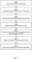
- FIG. 3 illustrating a method for migrating UEs 50a:50N from an S-IAB node 200 to an R-IAB node 300 as performed by the D-IAB node 100 according to an embodiment.
- the D-IAB node 100 obtains a request for replacement of the S-IAB node 200.
- the D-IAB node 100 provides, to the S-IAB node 200, an indication of replacement of the S-IAB node 200.
- the D-IAB node 100 obtains, from the S-IAB node 200, scheduling information for the UEs 50a:50N served by the S-IAB node 200.
- S110 The D-IAB node 100 forwards, to the R-IAB node 300, the scheduling information.
- the D-IAB node 100 initiates migration of at least a subset of the UEs 50a:50N from the S-IAB node 200 to the R-IAB node 300 by providing instructions, via the S-IAB node 200 to at least the subset of the UEs 50a:50N to switch from being served by the S-IAB node 200 to being served by the R-IAB node 300.
- Embodiments relating to further details of migrating UEs 50a:50N from an S-IAB node 200 to an R-IAB node 300 as performed by the D-IAB node 100 will now be disclosed.
- the decision to replace the S-IAB node 200 is made by the network administrator, e.g., based on a centralized monitoring data pool, in which the status of all IAB nodes is collected and stored, or by a fleet administrator when the IAB nodes are portable or mobile.
- the decision to replace the S-IAB node 200 might be signaled to the D-IAB node 100 via OAM signaling or fleet management signaling.
- the S-IAB node 200 itself requests for a replacement, e.g., when it has a run-out-off power warning, or when it detects a hardware/software fault that prevents its proper operation.
- the replacement request might be reported from the S-IAB node 200 to the D-IAB node 100 as a high layer signaling over the associated F1 interface.
- the request for replacement of the S-IAB node 200 is obtained from the S-IAB node 200 or from an entity external to the D-IAB node 100, the S-IAB node 200, and the R-IAB node 300.
- the R-IAB node 300 is activated when the D-IAB node 100 has obtained the request in step S102.
- the D-IAB node 100 is configured to perform (optional) step S104: S104: The D-IAB node 100 provides, upon having obtained the request for the replacement of the S-IAB node 200, instructions to the R-IAB node 300 for the R-IAB node 300 to be activated.
- the scheduling information is sent by the S-IAB node 200 to a management system in, or connected to, the D-IAB node 100 over over a logic operations and maintenance (OAM) channel.
- the D-IAB node 100 will then relay this information through its logic OAM channel to the R-IAB node 300.
- the OAM might poll the S-IAB node 200 for any changes in the scheduling to forward this information to the R-IAB node 300.
- the S-IAB node 200 sends the scheduling information to the CU in the D-IAB node 100 as a (non-UE associated) F1 Application Protocol message.
- the CU in the D-IAB node 100 then sends the received scheduling information to the R-IAB node 300 as a F1 Application Protocol message. That is, in some embodiments, the scheduling information is obtained and forwarded over a logic operations and maintenance channel or in an F1 Application Protocol message.
- downlink (DL) data is sent to the UEs 50a:50N via both the S-IAB node 200 and the R-IAB node 300 and/or uplink (UL) data from the UEs 50a:50N is received from both the S-IAB node 200 and the R-IAB node 300.
- DL downlink
- UL uplink
- the D-IAB node 100 is configured to perform (optional) step S112 and/or (optional) step S114: S112: The D-IAB node 100 duplicates downlink data messages destined for the UEs 50a:50N for forwarding of the downlink data messages to both the S-IAB node 200 and the R-IAB node 300 whilst the UEs 50a:50N are still served by the S-IAB node 200.
- the D-IAB node 100 receives uplink messages originating from the UEs 50a:50N from both the S-IAB node 200 and the R-IAB node 300 whilst the UEs 50a:50N are still served by the S-IAB node 200.
- replacement of the S-IAB node 200 involves migrating all the UEs 50a:50N from the S-IAB node 200 to R-IAB node 300 before the S-IAB node 200 ceases to function or is removed.
- the decision to migrate the UEs 50a:50N is triggered when a chosen signal strength metric, e.g., any of Received Signal Strength Indicator (RSSI), Reference Signal Receive Power (RSRP), Reference Signal Receive Quality (RSRQ), measured by each UE 50a:50N with respect to the R-IAB node 300 exceeds a pre-defined threshold.
- a chosen signal strength metric e.g., any of Received Signal Strength Indicator (RSSI), Reference Signal Receive Power (RSRP), Reference Signal Receive Quality (RSRQ), measured by each UE 50a:50N with respect to the R-IAB node 300 exceeds a pre-defined threshold.
- the pre-defined threshold might be selected such that a minimum Quality of Service (QoS) for a specific service can be guaranteed.
- the decision to migrate the UEs 50a:50N is triggered when a selected signal strength metric, e.g., any of RSSI, RSRP, RSRQ, measured by each UE 50a:50N with respect to the R-IAB node 300 is a predefined offset value better than the same signal strength metric measured from the S-IAB node 200.
- This triggering criterion can be used in combination with reducing the transmit power of the measurement signal transmitted from the S-IAB node 200.
- the decision to migrate the UEs 50a:50N is triggered when a certain fraction of the UEs 50a:50N whose measurement report satisfies the threshold.
- the decision to migrate all the UEs 50a:50N to the R-IAB node 300 is triggered based on the fraction of the UL transmissions being successfully decoded at the R-IAB node 300, referred to as packet success ratio (PSR).
- PSR packet success ratio
- the migration can then be triggered when the UL PSR at the R-IAB node 300 exceeds a certain predetermined threshold or when the UL PSR at the R-IAB node 300 exceeds the UL PSR at the S-IAB node 200.
- the D-IAB node 100 verifies that a trigger condition for migration of at least the subset of the UEs 50a:50N is fulfilled before initiating migration of at least the subset of the UEs 50a:50N.
- the trigger condition pertains to link quality between the UEs 50a:50N and R-IAB node 300, without pertaining to link quality between UEs 50a:50N and S-IAB node 200.
- the S-IAB node 200 informs the R-IAB node 300 of uplink grants for the UEs 50a:50N.
- the D-IAB node 100 is configured to perform (optional) steps S116 and S118: S104:
- the D-IAB node 100 obtains, from the S-IAB node 200, information of uplink grants according to which the UEs 50a:50N served by the S-IAB node 200 are to send handover complete messages to the R-IAB node 300 upon completion of the migration.
- the D-IAB node 100 forwards the information of uplink grants to the R-IAB node 300.
- the UEs 50a:50N are notified of the uplink grants when being provided with the instructions in step S120 from the D-IAB node 100.
- the uplink grant information could be sent via the same means as the scheduling information is sent to the R-IAB node 300 from the S-IAB node 200, i.e., over an OAM channel or using dedicated FLAP messages.
- migration is initiated of at least a subset of the UEs 50a:50N from the S-IAB node 200 to the R-IAB node 300.
- the subset of UEs 50a:50N is selected based on service type, e.g. MC services.
- the subset of UEs 50a:50N is selected according to a criterion pertaining to a priority order as given by service type for the UEs 50a:50N.
- Migration of UEs 50a:50N having MC services might thereby be prioritized over migration of UEs 50a:50N having non-MC services
- the UEs 50a:50N are instructed to switch from being served by the S-IAB node 200 to being served by the R-IAB node 300 by being instructed to use an identifier of the R-IAB node 300 in all places where an identifier of the S-IAB node 200 is used.
- FIG. 4 illustrating a method for migrating UEs 50a:50N from an S-IAB node 200 to an R-IAB node 300 as performed by the S-IAB node 200 according to an embodiment.
- the S-IAB node 200 obtains, from the D-IAB node 100 of the S-IAB node 200 and the R-IAB node 300, an indication for replacement of the S-IAB node 200.
- the S-IAB node 200 provides, to the R-IAB node 300 and via the D-IAB node 100, scheduling information for the UEs 50a:50N served by the S-IAB node 200.
- the S-IAB node 200 initiates migration of at least a subset of the UEs 50a:50N from the S-IAB node 200 to the R-IAB node 300 by instructing, according to instructions from the D-IAB node 100, at least the subset of the UEs 50a:50N to switch from being served by the S-IAB node 200 to being served by the R-IAB node 300.
- Embodiments relating to further details of migrating UEs 50a:50N from an S-IAB node 200 to an R-IAB node 300 as performed by the S-IAB node 200 will now be disclosed.
- the S-IAB node 200 itself requests for a replacement, e.g., when it has a run-out-off power warning, or when it detects a hardware/software fault that prevents its proper operation.
- the S-IAB node 200 is configured to perform (optional) step S202: S202: The S-IAB node 200 provides, to the D-IAB node 100, a request for the replacement of the S-IAB node 200.
- the scheduling information is provided over a logic operations and maintenance channel or in an F1 Application Protocol message.
- the precoders, or beamforming weights, at the S-IAB node 200 and the R-IAB node 300 should be selected such that the UEs 50a:50N receive power from both of the S-IAB node 200 and the R-IAB node 300 and so that the UEs 50a:50N are unaware of the transmissions from R-IAB 300 and can still continue to transmit and receive data. Since a UE 50a:50N is unaware of a transmission from R-IAB node 300 at this point, the UE 50a:50N cannot report a precoder to be used by the R-IAB node 300 for transmission towards it.
- the number of transmit spatial layers, or rank, towards all UEs 50a:50N is fixed to 1 and a precoder that performs non-frequency-selective wide-beam transmission is selected for both the S-IAB node 200 and the R-IAB node 300.
- the number of transmit spatial layers, or rank, towards all UEs 50a:50N is fixed to 1
- the S-IAB node 200 uses the precoder reported by the UE 50a:50N for rank 1
- the S-IAB node 200 instructs the R-IAB node 300 to perform a non-frequency-selective wide-beam transmission.
- the number of transmit spatial layers to be used for transmission towards the UEs 50a:50N until the UEs 50a:50N have been migrated is fixed to 1.
- the R-IAB node 300 is to use non-frequency selective wide-beam transmission when communicating with the UEs 50a:50N until the UEs 50a:50N have been migrated.
- the scheduling information for each of the UEs 50a:50N specifies at least one of: time/frequency resources, modulation and coding scheme, transmission rank, precoder to be used, reference signal configuration.
- the S-IAB node 200 informs the R-IAB node 300 of uplink grants for the UEs 50a:50N.
- the S-IAB node 200 is configured to perform (optional) step S208: S208:
- the S-IAB node 200 provides, to the R-IAB node 300 and via the D-IAB node 100, information of uplink grants according to which the UEs 50a:50N served by the S-IAB node 200 are to send handover complete messages to the R-IAB node 300 upon completion of the migration.
- the instructions from the D-IAB node 100 then comprises a notification of the uplink grants.
- the UEs 50a:50N switch from being served by the S-IAB node 200 to being served by the R-IAB node 300.
- the UEs 50a:50N are instructed to switch from being served by the S-IAB node 200 to being served by the R-IAB node 300 by being instructed to use an identifier of the R-IAB node 300 in all places where an identifier of the S-IAB node 200 is used.
- FIG. 5 illustrating a method for migrating UEs 50a:50N from an S-IAB node 200 to an R-IAB node 300 as performed by the R-IAB node 300 according to an embodiment.
- the R-IAB node 300 obtains S308, from the S-IAB node 200 and via the D-IAB node 100 of the S-IAB node 200 and the R-IAB node 300, scheduling information for the UEs 50a:50N served by the S-IAB node 200.
- the R-IAB node 300 serves, according to the scheduling information, at least a subset of the UEs 50a:50N upon the subset of the UEs 50a:50N having migrated from being served by the S-IAB node 200 to being served by the R-IAB node 300.
- Embodiments relating to further details of migrating UEs 50a:50N from an S-IAB node 200 to an R-IAB node 300 as performed by the R-IAB node 300 will now be disclosed.
- the R-IAB node 300 is activated when the D-IAB node 100 has obtained the request in step S102.
- the R-IAB node 300 is configured to perform (optional) steps S302 and S304: S302: The R-IAB node 300 obtains, from the D-IAB node 100, instructions for the R-IAB node 300 to be activated.
- S304 The R-IAB node 300, in response thereto (i.e., in response to having obtained the instructions), establishes backhaul connectivity to the D-IAB node 100.
- the R-IAB node 300 Upon having been activated, the R-IAB node 300 might start transmitting reference signals, and optionally, the same system information as transmitted from the S-IAB node 200. That is, according to an embodiment, the R-IAB node 300 is configured to perform (optional) step S306: S306: The R-IAB node 300 starts transmitting reference signals (and, optionally, the same system information as transmitted from the S-IAB node 200) towards the UEs 50a:50N upon having established the backhaul connectivity to the D-IAB node 100.
- the scheduling information is obtained over a logic operations and maintenance channel or in an F1 Application Protocol message.
- the number of transmit spatial layers to be used for transmission towards the UEs 50a:50N until the UEs 50a:50N have been migrated is fixed to 1.
- the R-IAB node 300 is to use non-frequency selective wide-beam transmission when communicating with the UEs 50a:50N until the UEs 50a:50N have been migrated.
- the scheduling information for each of the UEs 50a:50N specifies at least one of: time/frequency resources, modulation and coding scheme, transmission rank, precoder to be used, reference signal configuration.
- DL data is sent to the UEs 50a:50N via both the S-IAB node 200 and the R-IAB node 300.
- the R-IAB node 300 is configured to perform (optional) step S310: S310: The R-IAB node 300 communicates downlink data messages and uplink data messages with the UEs 50a:50N according to the scheduling information whilst the UEs 50a:50N are still served by the S-IAB node 200.
- UL data from the UEs 50a:50N is received by the D-IAB node 100 from both the S-IAB node 200 and the R-IAB node 300.
- the R-IAB node 300 is configured to perform (optional) step S312: S312: The R-IAB node 300 obtains, from the S-IAB node 200 and via the D-IAB node 100, information of uplink grants according to which the UEs 50a:50N served by the S-IAB node 200 are to send handover complete messages to the R-IAB node 300 upon completion of the migration.
- Downlink user data and uplink data is communicated between the S-IAB node 200 and the UEs 50a:50N served by the S-IAB 200.
- the D-IAB node 100 obtains a request that the S-IAB node 200 needs replacement.
- the request for replacement of the S-IAB node 200 is obtained from the S-IAB node 200
- the request for replacement of the S-IAB node 200 is obtained from an external entity (i.e., an entity external to the D-IAB node 100, the S-IAB node 200, and the R-IAB node 300)
- the D-IAB 100 triggers the R-IAB node to be activated.
- An IAB integration procedure is performed for the R-IAB 300 to establish backhaul connectivity between the R-IAB node 300 and the D-IAB node 100. After backhaul establishment, the R-IAB node 300 starts broadcast of reference signals.
- S404, S405, S406, S407 Measurement configuration and measurement reporting.
- the D-IAB node 100 node adds information of the R-IAB node 300 to its neighbor list and includes the information in an RRC reconfiguration message. This message is, via the S-IAB 200, delivered to all UEs 50a:50N served by S-IAB node 200. These UEs 50a:50N can perform measurements on access links to the R-IAB node 300 and report these measurements to the S-IAB node 200 accordingly.
- the D-IAB node 100 signals the RRC reconfiguration message over the F1 interface to the S-IAB node 200 (step S404), and the S-IAB node 200 forwards the RRC reconfiguration message to all the UEs (step S406).
- the S-IAB node 200 also signals a UE specific measurement reporting configuration to each of the served UEs 50a:50N via dedicated RRC signaling.
- the content of the measurement reporting includes the time/frequency resources to use for the reporting and the format to use for the reporting.
- the UEs 50a:50N After receiving the measurement configuration, the UEs 50a:50N measure the link quality with respect to R-IAB node 300 by measuring on the reference signals transmitted by R-IAB node 300. The UEs 50a:50N send their measurement reports to the S-IAB node 200 (step S406). The S-IAB node 200 forwards the measurement reports to the D-IAB node 100 (step S407).
- Steps S404-S407 might be omitted when Automatic Neighbor Relation (ANR) is enabled, in which case the UEs 50a:50N discover a new cell (as defined by the R-IAB 300) without being explicitly instructed, or configured, to do so and report the measurements on signals from the R-IAB 300 to the serving cell (as defined by S-IAB 200).
- ANR Automatic Neighbor Relation
- the D-IAB node 100 triggers the following steps for performing joint transmission and reception.
- the D-IAB 100 sends a UE context setup request message to the R-IAB node 300 (step S408) and the R-IAB node 300 responds with a UE context setup response message to the D-IAB 100.
- the UE context setup request message requests the R-IAB node 300 to prepare for the handover of a UE 50a:50N and provides the R-IAB node 300 with information related to the UE 50a:50N.
- the information consists of, among other things, the necessary information required to maintain the network services towards an active UE 50a:50N, such as UE state information, UE identities, security information and UE capability information.
- the R-IAB node 300 responds with a UE context setup response when the preparation for the handover is successful.
- the UE context setup request and response procedure is repeated for all the UEs 50a:50N being served by the S-IAB node 200.
- a context setup request for all the UEs 50a:50N currently served by the S-IAB node 200 is sent to the R-IAB node 300 in a single request message and the R-IAB node 300 responds with a single response message.
- the S-IAB node 200 and the R-IAB node 300 use the same scheduling information. This can be achieved using the different options as disclosed above.
- the S-IAB node 200 continues to schedule the served UEs 50a:50N and the scheduling information is forwarded to the R-IAB node 300 through the D-IAB node 100.
- the scheduling decision is made by taking the control signaling forwarding delay into account. For instance, to account for the delay in forwarding to the R-IAB node 300, the S-IAB node 200 schedules its transmissions a few time slots in advance.
- the scheduling information transmitted to R-IAB node 300 contains the information necessary for simultaneous transmission, including but not limited to, the time/frequency resources for every served UE 50a:50N, modulation and coding scheme used, transmission rank used, precoder to be used, reference signal configuration, etc.
- PDCP packets intended for the UEs 50a:50N are duplicated at the D-IAB node 100 and sent to both the S-IAB node 200 and the R-IAB node 300.
- the scheduling information (from step S410) available at both the S-IAB node 200 and R-IAB node 300 identical signals are transmitted from the S-IAB node 200 and R-IAB node 300 to the UEs 50a:50N. Since the signals transmitted from the IAB child nodes (i.e., from the S-IAB node 200 and the R-IAB node 300) are identical, the coordinated transmission is transparent to the UEs 50a:50N with the effective channel being different.
- the DL reception timing for receiving DL transmissions from the S-IAB node 200 might also be used for the reception of the joint transmissions from both S-IAB node 200 and R-IAB node 300.
- the cell timing synchronization accuracy between S-IAB node 200 and the R-IAB node 300 has to be within a desired value, such as 3 ⁇ s
- a desired value such as 3 ⁇ s
- Existing over-the-air synchronization mechanisms e.g., variants of the IEEE 1588 precision-time-protocol, can be utilized to enable this.
- both the S-IAB node 200 and the R-IAB node 300 independently of each other decode packets received from the UEs 50a:50N and forward the decoded packets to the D-IAB node 100.
- the D-IAB node 100 receives the packets from the S-IAB node 200 and the R-IAB node 300 and removes any duplicate packets received from both the S-IAB node 200 and the R-IAB node 300 before forwarding the packets to the core network.
- the R-IAB node 300 and the S-IAB node 200 are located close to each other such that the propagation delay between the S-IAB node 200 and a given UE, and the propagation delay between the R-IAB node 300 and the same given UE is similar.
- the timing advance (TA) for UL transmissions with respect to the S-IAB node 200 already available at the UEs 50a:50N also serves as the TA for the UL transmission to both the S-IAB node 200 and the R-IAB node 300.
- S413-S420 Migration of UEs 50a:50N from the S-IAB node200 to the R-IAB node 300.
- the D-IAB node 100 instructs the S-IAB node 200 to begin the migration procedure (step S413).
- the S-IAB node 200 determines UL grants for the UEs 50a:50N to perform UL transmissions carrying handover complete (RRC Reconfiguration Complete) message towards the R-IAB node 300 (step S414).
- the determined UL grant is sent to the R-IAB node 300 via the D-IAB node 100 using the mechanisms detailed in step S410.
- a UE handover instruction message is sent by the D-IAB node 100 to the UEs 50a:50N via the S-IAB node 200, instructing the UEs 50a:50N to switch to the R-IAB node 300 (step S415).
- the UE handover instruction message also includes the TA and the UL grants to be used by the UEs 50a:50N for transmission towards the R-IAB node 300.
- the S-IAB node 200 When the S-IAB node 200 receives the UE handover instruction message from the D-IAB node 100, the S-IAB node 200 acknowledges receipt of the message to the D-IAB node 100 (step S416).
- the UEs 50a:50N transmit a RRC Reconfiguration Complete message to the R-IAB node 300 confirming that the UEs 50a:50N have established a connection to the R-IAB node 300 (step S417).
- the R-IAB node 300 forwards the received messages to the D-IAB node 100 (step S418).
- the UE context from the S-IAB node 200 is released (steps S419 and S420) and the S-IAB node 200 can be withdrawn from operation.
- Fig. 7 schematically illustrates, in terms of a number of functional units, the components of a D-IAB node 100 according to an embodiment.
- Processing circuitry 110 is provided using any combination of one or more of a suitable central processing unit (CPU), multiprocessor, microcontroller, digital signal processor (DSP), etc., capable of executing software instructions stored in a computer program product 1310a (as in Fig. 13 ), e.g. in the form of a storage medium 130.
- the processing circuitry 110 may further be provided as at least one application specific integrated circuit (ASIC), or field programmable gate array (FPGA).
- ASIC application specific integrated circuit
- FPGA field programmable gate array
- the processing circuitry 110 is configured to cause the D-IAB node 100 to perform a set of operations, or steps, as disclosed above.
- the storage medium 130 may store the set of operations
- the processing circuitry 110 may be configured to retrieve the set of operations from the storage medium 130 to cause the D-IAB node 100 to perform the set of operations.
- the set of operations may be provided as a set of executable instructions.
- the processing circuitry 110 is thereby arranged to execute methods as herein disclosed.
- the storage medium 130 may also comprise persistent storage, which, for example, can be any single one or combination of magnetic memory, optical memory, solid state memory or even remotely mounted memory.
- the D-IAB node 100 may further comprise a communications interface 120 for communications with the S-IAB node 200, the R-IAB node 300 and the UEs 50a:50N.
- the communications interface 120 may comprise one or more transmitters and receivers, comprising analogue and digital components.
- the processing circuitry 110 controls the general operation of the D-IAB node 100 e.g. by sending data and control signals to the communications interface 120 and the storage medium 130, by receiving data and reports from the communications interface 120, and by retrieving data and instructions from the storage medium 130.
- Other components, as well as the related functionality, of the D-IAB node 100 are omitted in order not to obscure the concepts presented herein.
- Fig. 8 schematically illustrates, in terms of a number of functional modules, the components of a D-IAB node 100 according to an embodiment.
- the D-IAB node 100 of Fig. 8 comprises a number of functional modules; an obtain module 110a configured to perform step S102, a provide module 110c configured to perform step S106, an obtain module 110d configured to perform step S108, a forward module 110e configured to perform step S110, and an initiate module 110j configured to perform step S120.
- 8 may further comprise a number of optional functional modules, such as any of a provide module 110b configured to perform step S104, a duplicate module 110f configured to perform step S112, a receive module 110g configured to perform step S114, an obtain module 110h configured to perform step S116, a provide module 110i configured to perform step S118.
- a provide module 110b configured to perform step S104
- a duplicate module 110f configured to perform step S112
- a receive module 110g configured to perform step S114
- an obtain module 110h configured to perform step S116
- a provide module 110i configured to perform step S118.
- each functional module 110a-110j may be implemented in hardware or in software.
- one or more or all functional modules 110a-110j may be implemented by the processing circuitry 110, possibly in cooperation with the communications interface 120 and the storage medium 130.
- the processing circuitry 110 may thus be arranged to from the storage medium 130 fetch instructions as provided by a functional module 110a-110j and to execute these instructions, thereby performing any steps of the D-IAB node 100 as disclosed herein.
- Fig. 9 schematically illustrates, in terms of a number of functional units, the components of an S-IAB node 200 according to an embodiment.
- Processing circuitry 210 is provided using any combination of one or more of a suitable central processing unit (CPU), multiprocessor, microcontroller, digital signal processor (DSP), etc., capable of executing software instructions stored in a computer program product 1310b (as in Fig. 13 ), e.g. in the form of a storage medium 230.
- the processing circuitry 210 may further be provided as at least one application specific integrated circuit (ASIC), or field programmable gate array (FPGA).
- ASIC application specific integrated circuit
- FPGA field programmable gate array
- the processing circuitry 210 is configured to cause the S-IAB node 200 to perform a set of operations, or steps, as disclosed above.
- the storage medium 230 may store the set of operations
- the processing circuitry 210 may be configured to retrieve the set of operations from the storage medium 230 to cause the S-IAB node 200 to perform the set of operations.
- the set of operations may be provided as a set of executable instructions.
- the processing circuitry 210 is thereby arranged to execute methods as herein disclosed.
- the storage medium 230 may also comprise persistent storage, which, for example, can be any single one or combination of magnetic memory, optical memory, solid state memory or even remotely mounted memory.
- the S-IAB node 200 may further comprise a communications interface 220 for communications with the D-IAB node 100, the R-IAB node 300 and the UEs 50a:50N.
- the communications interface 220 may comprise one or more transmitters and receivers, comprising analogue and digital components.
- the processing circuitry 210 controls the general operation of the S-IAB node 200 e.g. by sending data and control signals to the communications interface 220 and the storage medium 230, by receiving data and reports from the communications interface 220, and by retrieving data and instructions from the storage medium 230.
- Other components, as well as the related functionality, of the S-IAB node 200 are omitted in order not to obscure the concepts presented herein.
- Fig. 10 schematically illustrates, in terms of a number of functional modules, the components of an S-IAB node 200 according to an embodiment.
- the S-IAB node 200 of Fig. 10 comprises a number of functional modules; an obtain module 210b configured to perform step S204, a provide module 210c configured to perform step S206, and an initiate module 210e configured to perform step S210.
- the S-IAB node 200 of Fig. 10 may further comprise a number of optional functional modules, such as any of a provide module 210a configured to perform step S202, and a provide module 210d configured to perform step S208.
- each functional module 210a-210e may be implemented in hardware or in software.
- one or more or all functional modules 210a-210e may be implemented by the processing circuitry 210, possibly in cooperation with the communications interface 220 and the storage medium 230.
- the processing circuitry 210 may thus be arranged to from the storage medium 230 fetch instructions as provided by a functional module 210a-210e and to execute these instructions, thereby performing any steps of the S-IAB node 200 as disclosed herein.
- Fig. 11 schematically illustrates, in terms of a number of functional units, the components of an R-IAB node 300 according to an embodiment.
- Processing circuitry 310 is provided using any combination of one or more of a suitable central processing unit (CPU), multiprocessor, microcontroller, digital signal processor (DSP), etc., capable of executing software instructions stored in a computer program product 1310c (as in Fig. 13 ), e.g. in the form of a storage medium 330.
- the processing circuitry 310 may further be provided as at least one application specific integrated circuit (ASIC), or field programmable gate array (FPGA).
- ASIC application specific integrated circuit
- FPGA field programmable gate array
- the processing circuitry 310 is configured to cause the R-IAB node 300 to perform a set of operations, or steps, as disclosed above.
- the storage medium 330 may store the set of operations
- the processing circuitry 310 may be configured to retrieve the set of operations from the storage medium 330 to cause the R-IAB node 300 to perform the set of operations.
- the set of operations may be provided as a set of executable instructions.
- the processing circuitry 310 is thereby arranged to execute methods as herein disclosed.
- the storage medium 330 may also comprise persistent storage, which, for example, can be any single one or combination of magnetic memory, optical memory, solid state memory or even remotely mounted memory.
- the R-IAB node 300 may further comprise a communications interface 320 for communications with the S-IAB node 200, the D-IAB node 100 and the UEs 50a:50N.
- the communications interface 320 may comprise one or more transmitters and receivers, comprising analogue and digital components.
- the processing circuitry 310 controls the general operation of the R-IAB node 300 e.g. by sending data and control signals to the communications interface 320 and the storage medium 330, by receiving data and reports from the communications interface 320, and by retrieving data and instructions from the storage medium 330.
- Other components, as well as the related functionality, of the R-IAB node 300 are omitted in order not to obscure the concepts presented herein.
- Fig. 12 schematically illustrates, in terms of a number of functional modules, the components of an R-IAB node 300 according to an embodiment.
- the R-IAB node 300 of Fig. 12 comprises a number of functional modules; an obtain module 310d configured to perform step S308, and a serve module 310g configured to perform step S314.
- the R-IAB node 300 of Fig. 12 may further comprise a number of optional functional modules, such as any of an obtain module 310a configured to perform step S302, an establish module 310b configured to perform step S304, a transmit module 310c configured to perform step S306, a communication module 310e configured to perform step S310, and an obtain module 310f configured to perform step S312.
- each functional module 310a-310g may be implemented in hardware or in software.
- one or more or all functional modules 310a-310g may be implemented by the processing circuitry 310, possibly in cooperation with the communications interface 320 and the storage medium 330.
- the processing circuitry 310 may thus be arranged to from the storage medium 330 fetch instructions as provided by a functional module 310a-310g and to execute these instructions, thereby performing any steps of the R-IAB node 300 as disclosed herein.
- Fig. 13 shows one example of a computer program product 1310a, 1310b, 1310c comprising computer readable means 1330.
- a computer program 1320a can be stored, which computer program 1320a can cause the processing circuitry 110 and thereto operatively coupled entities and devices, such as the communications interface 120 and the storage medium 130, to execute methods according to embodiments described herein.
- the computer program 1320a and/or computer program product 1310a may thus provide means for performing any steps of the D-IAB node 100 as herein disclosed.
- a computer program 1320b can be stored, which computer program 1320b can cause the processing circuitry 210 and thereto operatively coupled entities and devices, such as the communications interface 220 and the storage medium 230, to execute methods according to embodiments described herein.
- the computer program 1320b and/or computer program product 1310b may thus provide means for performing any steps of the S-IAB node 200 as herein disclosed.
- a computer program 1320c can be stored, which computer program 1320c can cause the processing circuitry 310 and thereto operatively coupled entities and devices, such as the communications interface 320 and the storage medium 330, to execute methods according to embodiments described herein.
- the computer program 1320c and/or computer program product 1310c may thus provide means for performing any steps of the R-IAB node 300 as herein disclosed.
- the computer program product 1310a, 1310b, 1310c is illustrated as an optical disc, such as a CD (compact disc) or a DVD (digital versatile disc) or a Blu-Ray disc.
- the computer program product 1310a, 1310b, 1310c could also be embodied as a memory, such as a random access memory (RAM), a read-only memory (ROM), an erasable programmable read-only memory (EPROM), or an electrically erasable programmable read-only memory (EEPROM) and more particularly as a non-volatile storage medium of a device in an external memory such as a USB (Universal Serial Bus) memory or a Flash memory, such as a compact Flash memory.
- RAM random access memory
- ROM read-only memory
- EPROM erasable programmable read-only memory
- EEPROM electrically erasable programmable read-only memory
- the computer program 1320a, 1320b, 1320c is here schematically shown as a track on the depicted optical disk, the computer program 1320a, 1320b, 1320c can be stored in any way which is suitable for the computer program product 1310a, 1310b, 1310c.
Landscapes
- Engineering & Computer Science (AREA)
- Computer Networks & Wireless Communication (AREA)
- Signal Processing (AREA)
- Mobile Radio Communication Systems (AREA)
Description
- Embodiments presented herein relate to methods, a donor integrated access and backhaul (D-IAB) node, a serving integrated access and backhaul (S-IAB) node, a replacement integrated access and backhaul (R-IAB) node, computer programs, and a computer program product for migrating User Equipment (UE) from the S-IAB node to the R-IAB node.
- In communications networks, there may be a challenge to obtain good performance and capacity for a given communications protocol, its parameters and the physical environment in which the communications network is deployed.
- For example, densification via the deployment of more and more base stations (be them macro or micro base stations) is one of the mechanisms that can be employed to increase coverage, bandwidth and/or capacity in a communication network. However, deploying optical fiber links, or other types of cables, to the small cells, which is the usual way in which small cells are deployed, can end up being both expensive and impractical. Employing wireless links for connecting the small cells to the core network might be both cheaper and more practical. One such option is Integrated Access and Backhaul (IAB) networks, where part of the radio resources can be utilized for backhaul purposes (i.e., for communication between two IAB nodes).
- In general terms, an IAB network might comprise of a donor IAB node, parent IAB nodes, and child IAB nodes. In this respect, the donor IAB node also acts as parent IAB node and a child IAB node might act as parent IAB node to another child IAB node. To readily extend the network coverage using IAB network, a child IAB node can be expected to be carried by a vehicle, such as connected and autonomous vehicle (CAV) such as aerial vehicles and ground vehicle platforms, potentially making the IAB child node portable or mobile. In such a scenario, a currently deployed child IAB node may have to be replaced by another child IAB node. For instance, a child IAB node mounted on a CAV to extend network coverage during a mission-critical (MC) operation may have to be replaced due to its battery draining out.
- Existing procedures for such replacement of child IAB nodes could result in an unacceptably long interruption of the ongoing service for the served UEs.
- Hence, there is still a need for improved replacement of child IAB nodes in an IAB network.
-
WO 2020/067736 A1 relates to improving migration of a wireless device (a UE or an IAB node) from source IAB node to a target IAB node connected to the same donor IAB node. Upon receiving a measurement report from a UE via the source IAB node, the CU of the donor IAB node performs context establishment procedure with the target IAB node, and then sends a message UE context modification message to the source IAB node carrying RRC connection modification message for the UE and indicating to the source IAB node to stop sending data to the UE. The source IAB node forwards the RRC message to the UE, and sends to the CU of the IAB donor a message indicating whether there are UL data packets that are still not sent from the source IAB node to the CU of the donor IAB node. If yes, the CU of the donor IAB node waits until the last UL packet is received before it proceeds with the rest of the handover procedure. - 3GPP DRAFT R2-1812405 relates to IAB node migration and discloses that said migration is based on intra-gNB handover procedure which may be triggered by measurement reports received from an MT part of an IAB node, or may be triggered by a central route management entity. Donor gNB CU receives a measurement report form the MT of the IAB node to be migrated via source IAB node, makes a HO decision and sends a HO request to target IAB-DU. The target IAB-DU responds with HO acknowledge. The donor CU sends handover command to the MT, which detaches from the source IAB and synchronizes with the target IAB. Source DU sends F1 DL delivery status PDU to the donor CU, and the donor CU forwards DL packets to the target IAB node. After the handover complete message is received from the target IAB node, a route update message for the migrated IAB node is sent to all affected IAB nodes.
US 2020/045596 A1 relates to handover acceleration in 5G, and discloses that after transmitting a handover command to a UE, a source gNB can start to send/bi-cast the DL packets to the UE and to the target gNB. The UE may receive data from both the serving gNB and the target gNB at the same time. Moreover, the source gNB may instruct the UE to access the target gNB at a pre-allocated subframe, which may be e.g. semi-persistent resource allocation for the UE. The source gNB informs the target gNB about UL SN status and the pre-allocated resources. The target gNB directly transmits in the pre-allocated resources the PDCCS/PDSCH to the UE and receives UE UL data on the PUCCH at said resources. -
WO 2008/031258 A1 relates to improvement of HO procedure in LTE using inter-cell interference coordination. During HO preparation phase source eNB informs the target eNB how which resources it could reallocate from the source cell to the target cell due to handover of a UE to the target cell, wherein the source cell controller preferably selects the resources that are currently allocated for the UE. The target eNB accepts the offered resources and sends the answer in a response to the HO request. The UE is commanded to perform handover to the target cell, and once it accesses the target cell, it is scheduled in the reallocated resources. The resources relate to the frequency resources shared between neighbouring cells for inter-cell interference coordination. - An object of embodiments herein is to enable seamless replacement of child IAB nodes in an IAB network.
- According to a first aspect there is presented a method for migrating UEs from node to an R-IAB node. The method is performed by a D-IAB node of the S-IAB node and the R-IAB node. The method comprises obtaining a request for replacement of the S-IAB node. The method comprises providing, to the S-IAB node, an indication of replacement of the S-IAB node. The method comprises obtaining, from the S-IAB node, scheduling information for the UEs served by the S-IAB node. The method comprises forwarding, to the R-IAB node, the scheduling information. The method comprises initiating migration of at least a subset of the UEs from the S-IAB node to the R-IAB node by providing instructions, via the S-IAB node, to at least the subset of the UEs to switch from is served by the S-IAB node to is served by the R-IAB node.
- According to a second aspect there is presented a D-IAB node for migrating UEs from node to an R-IAB node. The D-IAB node comprises processing circuitry. The processing circuitry is configured to cause the D-IAB node to obtain a request for replacement of the S-IAB node. The processing circuitry is configured to cause the D-IAB node to provide, to the S-IAB node, an indication of replacement of the S-IAB node. The processing circuitry is configured to cause the D-IAB node to obtain, from the S-IAB node, scheduling information for the UEs served by the S-IAB node. The processing circuitry is configured to cause the D-IAB node to forward, to the R-IAB node, the scheduling information. The processing circuitry is configured to cause the D-IAB node to initiate migration of at least a subset of the UEs from the S-IAB node to the R-IAB node by providing instructions, via the S-IAB node, to at least the subset of the UEs to switch from is served by the S-IAB node to is served by the R-IAB node. According to a third aspect there is presented a computer program for migrating UEs from an S-IAB node to an R-IAB node. The computer program comprises computer program code which, when run on processing circuitry of a D-IAB node, causes the D-IAB node to perform the method according to the first aspect.
- According to a fourth aspect there is presented a method for migrating UEs from node to an R-IAB node. The method is performed by the S-IAB node. The method comprises obtaining, from a D-IAB node of the S-IAB node and the R-IAB node, an indication for replacement of the S-IAB node. The method comprises providing, to the R-IAB node and via the D-IAB node, scheduling information for the UEs served by the S-IAB node. The method comprises initiating migration of at least a subset of the UEs from the S-IAB node to the R-IAB node by instructing, according to instructions from the D-IAB node, at least the subset of the UEs to switch from is served by the S-IAB node to is served by the R-IAB node.
- According to a fifth aspect there is presented an S-IAB node for migrating UEs from the S-IAB node to an R-IAB node. The the S-IAB node comprises processing circuitry. The processing circuitry is configured to cause the the S-IAB node to obtain, from a D-IAB node of the S-IAB node and the R-IAB node, an indication for replacement of the S-IAB node. The processing circuitry is configured to cause the the S-IAB node to provide, to the R-IAB node and via the D-IAB node, scheduling information for the UEs served by the S-IAB node. The processing circuitry is configured to cause the the S-IAB node to initiate migration of at least a subset of the UEs from the S-IAB node to the R-IAB node by instructing, according to instructions from the D-IAB node, at least the subset of the UEs to switch from is served by the S-IAB node to is served by the R-IAB node.
- According to a sixth aspect there is presented a computer program for migrating UEs from an S-IAB node to an R-IAB node. The computer program comprises computer program code which, when run on processing circuitry of an S-IAB node, causes the S-IAB node to perform the method according to the fourth aspect.
- According to a seventh aspect there is presented a method for migrating UEs from node to an R-IAB node. The method is performed by the R-IAB node. The method comprises obtaining, from the S-IAB node and via a D-IAB node of the S-IAB node and the R-IAB node, scheduling information for the UEs served by the S-IAB node. The method comprises serving, according to the scheduling information, at least a subset of the UEs upon the subset of the UEs having migrated from is served by the S-IAB node to is served by the R-IAB node.
- According to an eighth aspect there is presented an R-IAB node for migrating UEs from node to the R-IAB node. The R-IAB node comprises processing circuitry. The processing circuitry is configured to cause the R-IAB node to obtain, from the S-IAB node and via a D-IAB node of the S-IAB node and the R-IAB node, scheduling information for the UEs served by the S-IAB node. The processing circuitry is configured to cause the R-IAB node to serve, according to the scheduling information, at least a subset of the UEs upon the subset of the UEs having migrated from is served by the S-IAB node to is served by the R-IAB node.
- According to a tenth aspect there is presented a computer program for migrating UEs from an S-IAB node to an R-IAB node. The computer program comprises computer program code which, when run on processing circuitry of an R-IAB node, causes the R-IAB node to perform the method according to the seventh aspect.
- According to a non-claimed eleventh aspect there is presented a computer program product comprising a computer program according to at least one of the third aspect, the sixth aspect, and the tenth aspect and a computer readable storage medium on which the computer program is stored. The computer readable storage medium can be a non-transitory computer readable storage medium.
- Advantageously these methods, this D-IAB node, this S-IAB node, this R-IAB node, these computer programs, and this computer program product provide efficient replacement of the S-IAB node with the R-IAB node in an IAB network.
- Advantageously these methods, this D-IAB node, this S-IAB node, this R-IAB node, these computer programs, and this computer program product enable seamless replacement of the S-IAB node with the R-IAB node in an IAB network.
- Advantageously these methods, this D-IAB node, this S-IAB node, this R-IAB node, these computer programs, and this computer program product enable replacement of the S-IAB node with the R-IAB node in an IAB network without interrupting ongoing services of the UEs.
- Advantageously these methods, this D-IAB node, this S-IAB node, this R-IAB node, these computer programs, and this computer product prevent service discontinuity during the migration, which is very crucial for MC services.
- Other objectives, features and advantages of the enclosed embodiments will be apparent from the following detailed disclosure, from the attached dependent claims as well as from the drawings. Generally, all terms used in the claims are to be interpreted according to their ordinary meaning in the technical field, unless explicitly defined otherwise herein. All references to "a/an/the element, apparatus, component, means, module, step, etc." are to be interpreted openly as referring to at least one instance of the element, apparatus, component, means, module, step, etc., unless explicitly stated otherwise. The steps of any method disclosed herein do not have to be performed in the exact order disclosed, unless explicitly stated.
- The inventive concept is now described, by way of example, with reference to the accompanying drawings, in which:
-
Fig. 1 is a schematic diagram illustrating an IAB network according to embodiments; -
Fig. 2 is a schematic illustration of interfaces between IAB nodes according to embodiments; -
Figs. 3 ,4 , and5 are flowcharts of methods according to embodiments; -
Fig. 6 is a signalling diagram according to an embodiment; -
Fig. 7 is a schematic diagram showing functional units of a D-IAB node according to an embodiment; -
Fig. 8 is a schematic diagram showing functional modules of a D-IAB node according to an embodiment; -
Fig. 9 is a schematic diagram showing functional units of an S-IAB node according to an embodiment; -
Fig. 10 is a schematic diagram showing functional modules of an S-IAB node according to an embodiment; -
Fig. 11 is a schematic diagram showing functional units of an R-IAB node according to an embodiment; -
Fig. 12 is a schematic diagram showing functional modules of an R-IAB node according to an embodiment; and -
Fig. 13 shows one example of a non-claimed computer program product comprising computer readable means. - The inventive concept will now be described more fully hereinafter with reference to the accompanying drawings, in which certain embodiments of the inventive concept are shown. This inventive concept may, however, be embodied in many different forms and should not be construed as limited to the embodiments set forth herein; rather, these embodiments are provided by way of example so that this disclosure will be thorough and complete, and will fully convey the scope of the inventive concept to those skilled in the art. Like numbers refer to like elements throughout the description. Any step or feature illustrated by dashed lines should be regarded as optional.
-
Fig. 1 is a schematic diagram illustrating anIAB network 10 where embodiments presented herein can be applied. TheIAB network 10 comprises a (radio)access network 20, acore network 30, and aservice network 40. In turn, the (radio)access network 20 comprises (radio) access network nodes in terms of threeIAB nodes IAB node 100 is the only of theIAB nodes connection 60, such as an optical fiber connection, to thecore network 30.IAB nodes core network 30 viawireless backhaul links IAB node 100. Hence,IAB node 100 provides wireless backhaul for theIAB nodes IAB node 100 will hereinafter therefore be referred to as a donor IAB (D-IAB) node whereasIAB nodes Fig. 1 , it is assumed thatUEs 50a:50N are served byIAB node 200 overwireless access links 80a, and that at least a subset of theseUEs 50a:50N is to be migrated so as to be served byIAB node 300 overwireless access links 80b.IAB node 200 will hereinafter therefore be referred to as a serving IAB (S-IAB) node andIAB node 300 will hereinafter therefore be referred to as a replacement IAB (R-IAB) node. D-IAB node 100 thus provides backhaul connectivity to the S-IAB node 200 and the R-IAB node 300 and is the entry point to the (radio)access network 20 from thecore network 30. - As defined in 3GPP TS 38.401 entitled "NG-RAN; Architecture description", version 16.1.0, the gNB is a logical node, which may be split into one central unit (CU) and one or more distributed units (DU). The CU hosts the higher layer protocols to the
UEs 50a:50N and terminates the control plane and user plane interfaces to the 5G core network (5GC). The CU controls the DU nodes over the F1 interface(s), where the DU node hosts the lower layers for the NR Uu interface to the UE. The IAB-D node 100 hosts a CU and a DU while each of the IAB child nodes only host DU which is connected to the donor CU functionality. The IAB child nodes with the DU are responsible for providing wireless access to theUEs 50a:50N and host the physical (PHY), medium access control (MAC) and radio link control (RLC) protocol layers. The IAB-D node 100 with the CU is responsible for Packet Data Convergence Protocol (PDCP) signaling and radio resource control (RRC) signaling. The mobile termination (MT) provides the physical interface for the wireless backhaul link between the IAB child nodes and the IAB-D node 100.Fig. 2 schematically illustrates interfaces over which the threeIAB nodes core network 30, and with theUEs 50a:50N. In this respect, the CU in the D-IAB node 100 is configured to communicate with thecore network 30. The CU in the D-IAB node 100 is configured to communicate with the DU in each of the S-IAB node 200 and the R-IAB node 300 over the F1 interface. The DU in the D-IAB node 100 is configured to communicate with the MT in each of the S-IAB node 200 and the R-IAB node 300 over the NR Uu interface. The DU in each of the S-IAB node 200 and the R-IAB node 300 is configured to communicate with theUEs 50a:50N over the NR Uu interface. - The embodiments disclosed herein thus relate to mechanisms for migrating
UEs 50a:50N from an S-IAB node 200 to an R-IAB node 300. In order to obtain such mechanisms there is provided a D-IAB node 100, a method performed by the D-IAB node 100, a computer program product comprising code, for example in the form of a computer program, that when run on processing circuitry of the D-IAB node 100, causes the D-IAB node 100 to perform the method. In order to obtain such mechanisms there is further provided an S-IAB node 200, a method performed by the S-IAB node 200, and a computer program product comprising code, for example in the form of a computer program, that when run on processing circuitry of the S-IAB node 200, causes the S-IAB node 200 to perform the method. In order to obtain such mechanisms there is further provided an R-IAB node 300, a method performed by the R-IAB node 300, and a computer program product comprising code, for example in the form of a computer program, that when run on processing circuitry of the R-IAB node 300, causes the R-IAB node 300 to perform the method. - Reference is now made to
Fig. 3 illustrating a method for migratingUEs 50a:50N from an S-IAB node 200 to an R-IAB node 300 as performed by the D-IAB node 100 according to an embodiment. - S102: The D-
IAB node 100 obtains a request for replacement of the S-IAB node 200. - S106: The D-
IAB node 100 provides, to the S-IAB node 200, an indication of replacement of the S-IAB node 200. - S108: The D-
IAB node 100 obtains, from the S-IAB node 200, scheduling information for theUEs 50a:50N served by the S-IAB node 200. - S110: The D-
IAB node 100 forwards, to the R-IAB node 300, the scheduling information. - S120: The D-
IAB node 100 initiates migration of at least a subset of theUEs 50a:50N from the S-IAB node 200 to the R-IAB node 300 by providing instructions, via the S-IAB node 200 to at least the subset of theUEs 50a:50N to switch from being served by the S-IAB node 200 to being served by the R-IAB node 300. - Embodiments relating to further details of migrating
UEs 50a:50N from an S-IAB node 200 to an R-IAB node 300 as performed by the D-IAB node 100 will now be disclosed. - In some examples, the decision to replace the S-
IAB node 200 is made by the network administrator, e.g., based on a centralized monitoring data pool, in which the status of all IAB nodes is collected and stored, or by a fleet administrator when the IAB nodes are portable or mobile. The decision to replace the S-IAB node 200 might be signaled to the D-IAB node 100 via OAM signaling or fleet management signaling. In other examples, the S-IAB node 200 itself requests for a replacement, e.g., when it has a run-out-off power warning, or when it detects a hardware/software fault that prevents its proper operation. The replacement request might be reported from the S-IAB node 200 to the D-IAB node 100 as a high layer signaling over the associated F1 interface. Thus, in some embodiments, the request for replacement of the S-IAB node 200 is obtained from the S-IAB node 200 or from an entity external to the D-IAB node 100, the S-IAB node 200, and the R-IAB node 300. - In some aspects, the R-
IAB node 300 is activated when the D-IAB node 100 has obtained the request in step S102. In particular, according to an embodiment, the D-IAB node 100 is configured to perform (optional) step S104:
S104: The D-IAB node 100 provides, upon having obtained the request for the replacement of the S-IAB node 200, instructions to the R-IAB node 300 for the R-IAB node 300 to be activated. - Further aspects of the scheduling information for the
UEs 50a:50N served by the S-IAB node 200 as obtained by the D-IAB node 100 in step S108 from the S-IAB node 200 will now be disclosed. - In a first example, the scheduling information is sent by the S-
IAB node 200 to a management system in, or connected to, the D-IAB node 100 over over a logic operations and maintenance (OAM) channel. The D-IAB node 100 will then relay this information through its logic OAM channel to the R-IAB node 300. The OAM might poll the S-IAB node 200 for any changes in the scheduling to forward this information to the R-IAB node 300. In a second example, the S-IAB node 200 sends the scheduling information to the CU in the D-IAB node 100 as a (non-UE associated) F1 Application Protocol message. The CU in the D-IAB node 100 then sends the received scheduling information to the R-IAB node 300 as a F1 Application Protocol message. That is, in some embodiments, the scheduling information is obtained and forwarded over a logic operations and maintenance channel or in an F1 Application Protocol message. - In some aspects, downlink (DL) data is sent to the
UEs 50a:50N via both the S-IAB node 200 and the R-IAB node 300 and/or uplink (UL) data from theUEs 50a:50N is received from both the S-IAB node 200 and the R-IAB node 300. Thus, according to an embodiment, the D-IAB node 100 is configured to perform (optional) step S112 and/or (optional) step S114:
S112: The D-IAB node 100 duplicates downlink data messages destined for theUEs 50a:50N for forwarding of the downlink data messages to both the S-IAB node 200 and the R-IAB node 300 whilst theUEs 50a:50N are still served by the S-IAB node 200. - S114: The D-
IAB node 100 receives uplink messages originating from theUEs 50a:50N from both the S-IAB node 200 and the R-IAB node 300 whilst theUEs 50a:50N are still served by the S-IAB node 200. - In general terms, as opposed to handover of an
individual UE 50a:50N from the S-IAB node 200 to the R-IAB node 300, replacement of the S-IAB node 200 involves migrating all the UEs 50a:50N from the S-IAB node 200 to R-IAB node 300 before the S-IAB node 200 ceases to function or is removed. There can be different triggers for performing the actual migration of theUEs 50a:50N from the S-IAB node 200 to the R-IAB node 300. In some non-limiting examples, the decision to migrate theUEs 50a:50N is triggered when a chosen signal strength metric, e.g., any of Received Signal Strength Indicator (RSSI), Reference Signal Receive Power (RSRP), Reference Signal Receive Quality (RSRQ), measured by eachUE 50a:50N with respect to the R-IAB node 300 exceeds a pre-defined threshold. The pre-defined threshold might be selected such that a minimum Quality of Service (QoS) for a specific service can be guaranteed. In some non-limiting examples, the decision to migrate theUEs 50a:50N is triggered when a selected signal strength metric, e.g., any of RSSI, RSRP, RSRQ, measured by eachUE 50a:50N with respect to the R-IAB node 300 is a predefined offset value better than the same signal strength metric measured from the S-IAB node 200. This triggering criterion can be used in combination with reducing the transmit power of the measurement signal transmitted from the S-IAB node 200. In some non-limiting examples, the decision to migrate theUEs 50a:50N is triggered when a certain fraction of theUEs 50a:50N whose measurement report satisfies the threshold. In some non-limiting examples, the decision to migrate all the UEs 50a:50N to the R-IAB node 300 is triggered based on the fraction of the UL transmissions being successfully decoded at the R-IAB node 300, referred to as packet success ratio (PSR). The migration can then be triggered when the UL PSR at the R-IAB node 300 exceeds a certain predetermined threshold or when the UL PSR at the R-IAB node 300 exceeds the UL PSR at the S-IAB node 200. In some embodiments, the D-IAB node 100 verifies that a trigger condition for migration of at least the subset of theUEs 50a:50N is fulfilled before initiating migration of at least the subset of theUEs 50a:50N. In some embodiments, the trigger condition pertains to link quality between the UEs 50a:50N and R-IAB node 300, without pertaining to link quality betweenUEs 50a:50N and S-IAB node 200. - As will be disclosed in more detail below, in some aspects, the S-
IAB node 200 informs the R-IAB node 300 of uplink grants for theUEs 50a:50N. Particularly, according to an embodiment, the D-IAB node 100 is configured to perform (optional) steps S116 and S118:
S104: The D-IAB node 100 obtains, from the S-IAB node 200, information of uplink grants according to which theUEs 50a:50N served by the S-IAB node 200 are to send handover complete messages to the R-IAB node 300 upon completion of the migration. - S118: The D-
IAB node 100 forwards the information of uplink grants to the R-IAB node 300. TheUEs 50a:50N are notified of the uplink grants when being provided with the instructions in step S120 from the D-IAB node 100. - The uplink grant information could be sent via the same means as the scheduling information is sent to the R-
IAB node 300 from the S-IAB node 200, i.e., over an OAM channel or using dedicated FLAP messages. - As disclosed above, migration is initiated of at least a subset of the
UEs 50a:50N from the S-IAB node 200 to the R-IAB node 300. There could be different ways to select whichUEs 50a:50N to be migrated. In some aspects, the subset ofUEs 50a:50N is selected based on service type, e.g. MC services. In particular, in some embodiments, the subset ofUEs 50a:50N is selected according to a criterion pertaining to a priority order as given by service type for theUEs 50a:50N. Migration ofUEs 50a:50N having MC services might thereby be prioritized over migration ofUEs 50a:50N having non-MC services How UEs 50a:50N switch from S-IAB node 200 to R-IAB node 300: switch identifiers - In some embodiments, the
UEs 50a:50N are instructed to switch from being served by the S-IAB node 200 to being served by the R-IAB node 300 by being instructed to use an identifier of the R-IAB node 300 in all places where an identifier of the S-IAB node 200 is used. - Reference is now made to
Fig. 4 illustrating a method for migratingUEs 50a:50N from an S-IAB node 200 to an R-IAB node 300 as performed by the S-IAB node 200 according to an embodiment. - S204: The S-
IAB node 200 obtains, from the D-IAB node 100 of the S-IAB node 200 and the R-IAB node 300, an indication for replacement of the S-IAB node 200. - S206: The S-
IAB node 200 provides, to the R-IAB node 300 and via the D-IAB node 100, scheduling information for theUEs 50a:50N served by the S-IAB node 200. - S210: The S-
IAB node 200 initiates migration of at least a subset of theUEs 50a:50N from the S-IAB node 200 to the R-IAB node 300 by instructing, according to instructions from the D-IAB node 100, at least the subset of theUEs 50a:50N to switch from being served by the S-IAB node 200 to being served by the R-IAB node 300. - Embodiments relating to further details of migrating
UEs 50a:50N from an S-IAB node 200 to an R-IAB node 300 as performed by the S-IAB node 200 will now be disclosed. - As disclosed above, in some examples, the S-
IAB node 200 itself requests for a replacement, e.g., when it has a run-out-off power warning, or when it detects a hardware/software fault that prevents its proper operation. Thus, according to an embodiment, the S-IAB node 200 is configured to perform (optional) step S202:
S202: The S-IAB node 200 provides, to the D-IAB node 100, a request for the replacement of the S-IAB node 200. - Aspects of how the scheduling information might be provided from the S-
IAB node 200 to the R-IAB node 300 via the D-IAB node 100 have been disclosed above and apply here as well. In some embodiments, the scheduling information is provided over a logic operations and maintenance channel or in an F1 Application Protocol message. - When performing non-coherent joint transmission of the same pieces of data, the precoders, or beamforming weights, at the S-
IAB node 200 and the R-IAB node 300 should be selected such that theUEs 50a:50N receive power from both of the S-IAB node 200 and the R-IAB node 300 and so that theUEs 50a:50N are unaware of the transmissions from R-IAB 300 and can still continue to transmit and receive data. Since aUE 50a:50N is unaware of a transmission from R-IAB node 300 at this point, theUE 50a:50N cannot report a precoder to be used by the R-IAB node 300 for transmission towards it. - Therefore, in some examples, to simplify the process of selecting precoders at both the S-
IAB node 200 and the R-IAB node 300 when performing simultaneous transmission, the number of transmit spatial layers, or rank, towards allUEs 50a:50N is fixed to 1 and a precoder that performs non-frequency-selective wide-beam transmission is selected for both the S-IAB node 200 and the R-IAB node 300. Further, in some examples, to simplify the process of selecting precoders at both the S-IAB node 200 and the R-IAB node 300 when performing simultaneous transmission the number of transmit spatial layers, or rank, towards allUEs 50a:50N is fixed to 1, and the S-IAB node 200 uses the precoder reported by theUE 50a:50N forrank 1, and the S-IAB node 200 instructs the R-IAB node 300 to perform a non-frequency-selective wide-beam transmission. Hence, in some embodiments, according to the scheduling information, the number of transmit spatial layers to be used for transmission towards theUEs 50a:50N until theUEs 50a:50N have been migrated is fixed to 1. Hence, in some embodiments, according to the scheduling information, the R-IAB node 300 is to use non-frequency selective wide-beam transmission when communicating with theUEs 50a:50N until theUEs 50a:50N have been migrated. In some non-limiting examples, the scheduling information for each of theUEs 50a:50N specifies at least one of: time/frequency resources, modulation and coding scheme, transmission rank, precoder to be used, reference signal configuration. - In some aspects, the S-
IAB node 200 informs the R-IAB node 300 of uplink grants for theUEs 50a:50N. Particularly, according to an embodiment, the S-IAB node 200 is configured to perform (optional) step S208:
S208: The S-IAB node 200 provides, to the R-IAB node 300 and via the D-IAB node 100, information of uplink grants according to which theUEs 50a:50N served by the S-IAB node 200 are to send handover complete messages to the R-IAB node 300 upon completion of the migration. The instructions from the D-IAB node 100 then comprises a notification of the uplink grants. - There could be different ways in which the
UEs 50a:50N switch from being served by the S-IAB node 200 to being served by the R-IAB node 300. In some embodiments, theUEs 50a:50N are instructed to switch from being served by the S-IAB node 200 to being served by the R-IAB node 300 by being instructed to use an identifier of the R-IAB node 300 in all places where an identifier of the S-IAB node 200 is used. - Reference is now made to
Fig. 5 illustrating a method for migratingUEs 50a:50N from an S-IAB node 200 to an R-IAB node 300 as performed by the R-IAB node 300 according to an embodiment. - S308: The R-
IAB node 300 obtains S308, from the S-IAB node 200 and via the D-IAB node 100 of the S-IAB node 200 and the R-IAB node 300, scheduling information for theUEs 50a:50N served by the S-IAB node 200. - S314: The R-
IAB node 300 serves, according to the scheduling information, at least a subset of theUEs 50a:50N upon the subset of theUEs 50a:50N having migrated from being served by the S-IAB node 200 to being served by the R-IAB node 300. - Embodiments relating to further details of migrating
UEs 50a:50N from an S-IAB node 200 to an R-IAB node 300 as performed by the R-IAB node 300 will now be disclosed. - As disclosed above, in some aspects, the R-
IAB node 300 is activated when the D-IAB node 100 has obtained the request in step S102. In particular, according to an embodiment, the R-IAB node 300 is configured to perform (optional) steps S302 and S304:
S302: The R-IAB node 300 obtains, from the D-IAB node 100, instructions for the R-IAB node 300 to be activated. - S304: The R-
IAB node 300, in response thereto (i.e., in response to having obtained the instructions), establishes backhaul connectivity to the D-IAB node 100. - Upon having been activated, the R-
IAB node 300 might start transmitting reference signals, and optionally, the same system information as transmitted from the S-IAB node 200. That is, according to an embodiment, the R-IAB node 300 is configured to perform (optional) step S306:
S306: The R-IAB node 300 starts transmitting reference signals (and, optionally, the same system information as transmitted from the S-IAB node 200) towards theUEs 50a:50N upon having established the backhaul connectivity to the D-IAB node 100. - Aspects of how the scheduling information might be provided from the S-
IAB node 200 to the R-IAB node 300 via the D-IAB node 100 have been disclosed above and apply here as well. In some embodiments, the scheduling information is obtained over a logic operations and maintenance channel or in an F1 Application Protocol message. As disclosed above, in some embodiments, according to the scheduling information, the number of transmit spatial layers to be used for transmission towards theUEs 50a:50N until theUEs 50a:50N have been migrated is fixed to 1. As disclosed above, in some embodiments, according to the scheduling information, the R-IAB node 300 is to use non-frequency selective wide-beam transmission when communicating with theUEs 50a:50N until theUEs 50a:50N have been migrated. As disclosed above, in some non-limiting examples, the scheduling information for each of theUEs 50a:50N specifies at least one of: time/frequency resources, modulation and coding scheme, transmission rank, precoder to be used, reference signal configuration. - As disclosed above, in some aspects, DL data is sent to the
UEs 50a:50N via both the S-IAB node 200 and the R-IAB node 300. Thus, according to an embodiment, the R-IAB node 300 is configured to perform (optional) step S310:
S310: The R-IAB node 300 communicates downlink data messages and uplink data messages with theUEs 50a:50N according to the scheduling information whilst theUEs 50a:50N are still served by the S-IAB node 200. - As disclosed above, in some aspects, UL data from the
UEs 50a:50N is received by the D-IAB node 100 from both the S-IAB node 200 and the R-IAB node 300. Thus, according to an embodiment, the R-IAB node 300 is configured to perform (optional) step S312:
S312: The R-IAB node 300 obtains, from the S-IAB node 200 and via the D-IAB node 100, information of uplink grants according to which theUEs 50a:50N served by the S-IAB node 200 are to send handover complete messages to the R-IAB node 300 upon completion of the migration. - One particular embodiment for migrating
UEs 50a:50N from an S-IAB node 200 to an R-IAB node 300 based on at least some of the above disclosed embodiments will now be disclosed in detail with reference to the signalling diagram ofFig. 6 . - S400: Data communication.
- Downlink user data and uplink data is communicated between the S-
IAB node 200 and theUEs 50a:50N served by the S-IAB 200. - S401: Initiation of S-
IAB node 200 replacement procedure. - The D-
IAB node 100 obtains a request that the S-IAB node 200 needs replacement. As disclosed above, in some examples the request for replacement of the S-IAB node 200 is obtained from the S-IAB node 200, whereas in other examples the request for replacement of the S-IAB node 200 is obtained from an external entity (i.e., an entity external to the D-IAB node 100, the S-IAB node 200, and the R-IAB node 300) - S402, S403: Activate R-
IAB node 300 and connection establishment. - The D-
IAB 100 triggers the R-IAB node to be activated. An IAB integration procedure is performed for the R-IAB 300 to establish backhaul connectivity between the R-IAB node 300 and the D-IAB node 100. After backhaul establishment, the R-IAB node 300 starts broadcast of reference signals. - S404, S405, S406, S407: Measurement configuration and measurement reporting.
- The D-
IAB node 100 node adds information of the R-IAB node 300 to its neighbor list and includes the information in an RRC reconfiguration message. This message is, via the S-IAB 200, delivered to allUEs 50a:50N served by S-IAB node 200. TheseUEs 50a:50N can perform measurements on access links to the R-IAB node 300 and report these measurements to the S-IAB node 200 accordingly. - The D-
IAB node 100 signals the RRC reconfiguration message over the F1 interface to the S-IAB node 200 (step S404), and the S-IAB node 200 forwards the RRC reconfiguration message to all the UEs (step S406). - The S-
IAB node 200 also signals a UE specific measurement reporting configuration to each of the servedUEs 50a:50N via dedicated RRC signaling. The content of the measurement reporting includes the time/frequency resources to use for the reporting and the format to use for the reporting. - After receiving the measurement configuration, the
UEs 50a:50N measure the link quality with respect to R-IAB node 300 by measuring on the reference signals transmitted by R-IAB node 300. TheUEs 50a:50N send their measurement reports to the S-IAB node 200 (step S406). The S-IAB node 200 forwards the measurement reports to the D-IAB node 100 (step S407). - Steps S404-S407 might be omitted when Automatic Neighbor Relation (ANR) is enabled, in which case the
UEs 50a:50N discover a new cell (as defined by the R-IAB 300) without being explicitly instructed, or configured, to do so and report the measurements on signals from the R-IAB 300 to the serving cell (as defined by S-IAB 200). - When the link quality reported by the
UEs 50a:50N with respect to R-IAB node 300 satisfies a certain criterion, for example when the link quality exceeds a threshold, the D-IAB node 100 triggers the following steps for performing joint transmission and reception. - S408, S409: UE context setup.
- The D-
IAB 100 sends a UE context setup request message to the R-IAB node 300 (step S408) and the R-IAB node 300 responds with a UE context setup response message to the D-IAB 100. - The UE context setup request message requests the R-
IAB node 300 to prepare for the handover of aUE 50a:50N and provides the R-IAB node 300 with information related to theUE 50a:50N. The information consists of, among other things, the necessary information required to maintain the network services towards anactive UE 50a:50N, such as UE state information, UE identities, security information and UE capability information. The R-IAB node 300 responds with a UE context setup response when the preparation for the handover is successful. - In an example, the UE context setup request and response procedure is repeated for all the UEs 50a:50N being served by the S-
IAB node 200. In another example, a context setup request for all the UEs 50a:50N currently served by the S-IAB node 200 is sent to the R-IAB node 300 in a single request message and the R-IAB node 300 responds with a single response message. - S410: Joint scheduling.
- To perform coordinated transmission and reception, the S-
IAB node 200 and the R-IAB node 300 use the same scheduling information. This can be achieved using the different options as disclosed above. - The S-
IAB node 200 continues to schedule the servedUEs 50a:50N and the scheduling information is forwarded to the R-IAB node 300 through the D-IAB node 100. The scheduling decision is made by taking the control signaling forwarding delay into account. For instance, to account for the delay in forwarding to the R-IAB node 300, the S-IAB node 200 schedules its transmissions a few time slots in advance. - The scheduling information transmitted to R-
IAB node 300 contains the information necessary for simultaneous transmission, including but not limited to, the time/frequency resources for every servedUE 50a:50N, modulation and coding scheme used, transmission rank used, precoder to be used, reference signal configuration, etc. - Examples of how the scheduling information can be transmitted from the S-
IAB node 200 to the R-IAB node 300 via D-IAB node 100 have been disclosed above and apply here as well. - S411: Coordinated/simultaneous DL data transmission.
- For DL transmissions, PDCP packets intended for the
UEs 50a:50N are duplicated at the D-IAB node 100 and sent to both the S-IAB node 200 and the R-IAB node 300. Using the scheduling information (from step S410) available at both the S-IAB node 200 and R-IAB node 300, identical signals are transmitted from the S-IAB node 200 and R-IAB node 300 to theUEs 50a:50N. Since the signals transmitted from the IAB child nodes (i.e., from the S-IAB node 200 and the R-IAB node 300) are identical, the coordinated transmission is transparent to theUEs 50a:50N with the effective channel being different. - At the UE side, the DL reception timing for receiving DL transmissions from the S-
IAB node 200 might also be used for the reception of the joint transmissions from both S-IAB node 200 and R-IAB node 300. - To perform simultaneous transmission without significant intersymbol interference, the cell timing synchronization accuracy between S-
IAB node 200 and the R-IAB node 300 has to be within a desired value, such as 3µs Existing over-the-air synchronization mechanisms, e.g., variants of the IEEE 1588 precision-time-protocol, can be utilized to enable this. - S412: Simultaneous UL data reception
- For UL transmissions, both the S-
IAB node 200 and the R-IAB node 300 independently of each other decode packets received from theUEs 50a:50N and forward the decoded packets to the D-IAB node 100. The D-IAB node 100 receives the packets from the S-IAB node 200 and the R-IAB node 300 and removes any duplicate packets received from both the S-IAB node 200 and the R-IAB node 300 before forwarding the packets to the core network. - In some aspects, the R-
IAB node 300 and the S-IAB node 200 are located close to each other such that the propagation delay between the S-IAB node 200 and a given UE, and the propagation delay between the R-IAB node 300 and the same given UE is similar. This implies that the timing advances of the given UE with respect to R-IAB node 300 will be similar to the timing advance of the same given UE with respect to the S-IAB node 200. Therefore, when theUEs 50a:50N perform an UL transmission towards the S-IAB node 200, the R-IAB node 300 can expect the transmission to be time aligned, within a fraction of the cyclic prefix duration, with UL transmissions of other UEs. - In some aspects, at the UE side, the timing advance (TA) for UL transmissions with respect to the S-
IAB node 200 already available at theUEs 50a:50N also serves as the TA for the UL transmission to both the S-IAB node 200 and the R-IAB node 300. - S413-S420: Migration of
UEs 50a:50N from the S-IAB node200 to the R-IAB node 300. - When any of the migration criteria as disclosed above is met, the D-
IAB node 100 instructs the S-IAB node 200 to begin the migration procedure (step S413). - The S-
IAB node 200 determines UL grants for theUEs 50a:50N to perform UL transmissions carrying handover complete (RRC Reconfiguration Complete) message towards the R-IAB node 300 (step S414). The determined UL grant is sent to the R-IAB node 300 via the D-IAB node 100 using the mechanisms detailed in step S410. - A UE handover instruction message is sent by the D-
IAB node 100 to theUEs 50a:50N via the S-IAB node 200, instructing theUEs 50a:50N to switch to the R-IAB node 300 (step S415). The UE handover instruction message also includes the TA and the UL grants to be used by theUEs 50a:50N for transmission towards the R-IAB node 300. - When the S-
IAB node 200 receives the UE handover instruction message from the D-IAB node 100, the S-IAB node 200 acknowledges receipt of the message to the D-IAB node 100 (step S416). - The
UEs 50a:50N transmit a RRC Reconfiguration Complete message to the R-IAB node 300 confirming that theUEs 50a:50N have established a connection to the R-IAB node 300 (step S417). The R-IAB node 300 forwards the received messages to the D-IAB node 100 (step S418). - When the RRC Reconfiguration Complete messages from all the UEs 50a:50N are received by the D-
IAB node 100, the UE context from the S-IAB node 200 is released (steps S419 and S420) and the S-IAB node 200 can be withdrawn from operation. -
Fig. 7 schematically illustrates, in terms of a number of functional units, the components of a D-IAB node 100 according to an embodiment.Processing circuitry 110 is provided using any combination of one or more of a suitable central processing unit (CPU), multiprocessor, microcontroller, digital signal processor (DSP), etc., capable of executing software instructions stored in acomputer program product 1310a (as inFig. 13 ), e.g. in the form of astorage medium 130. Theprocessing circuitry 110 may further be provided as at least one application specific integrated circuit (ASIC), or field programmable gate array (FPGA). - Particularly, the
processing circuitry 110 is configured to cause the D-IAB node 100 to perform a set of operations, or steps, as disclosed above. For example, thestorage medium 130 may store the set of operations, and theprocessing circuitry 110 may be configured to retrieve the set of operations from thestorage medium 130 to cause the D-IAB node 100 to perform the set of operations. The set of operations may be provided as a set of executable instructions. Thus theprocessing circuitry 110 is thereby arranged to execute methods as herein disclosed. - The
storage medium 130 may also comprise persistent storage, which, for example, can be any single one or combination of magnetic memory, optical memory, solid state memory or even remotely mounted memory. - The D-
IAB node 100 may further comprise acommunications interface 120 for communications with the S-IAB node 200, the R-IAB node 300 and theUEs 50a:50N. As such thecommunications interface 120 may comprise one or more transmitters and receivers, comprising analogue and digital components. - The
processing circuitry 110 controls the general operation of the D-IAB node 100 e.g. by sending data and control signals to thecommunications interface 120 and thestorage medium 130, by receiving data and reports from thecommunications interface 120, and by retrieving data and instructions from thestorage medium 130. Other components, as well as the related functionality, of the D-IAB node 100 are omitted in order not to obscure the concepts presented herein. -
Fig. 8 schematically illustrates, in terms of a number of functional modules, the components of a D-IAB node 100 according to an embodiment. The D-IAB node 100 ofFig. 8 comprises a number of functional modules; an obtainmodule 110a configured to perform step S102, a providemodule 110c configured to perform step S106, an obtainmodule 110d configured to perform step S108, aforward module 110e configured to perform step S110, and an initiatemodule 110j configured to perform step S120. The D-IAB node 100 ofFig. 8 may further comprise a number of optional functional modules, such as any of a providemodule 110b configured to perform step S104, aduplicate module 110f configured to perform step S112, a receivemodule 110g configured to perform step S114, an obtainmodule 110h configured to perform step S116, a providemodule 110i configured to perform step S118. - In general terms, each
functional module 110a-110j may be implemented in hardware or in software. Preferably, one or more or allfunctional modules 110a-110j may be implemented by theprocessing circuitry 110, possibly in cooperation with thecommunications interface 120 and thestorage medium 130. Theprocessing circuitry 110 may thus be arranged to from thestorage medium 130 fetch instructions as provided by afunctional module 110a-110j and to execute these instructions, thereby performing any steps of the D-IAB node 100 as disclosed herein. -
Fig. 9 schematically illustrates, in terms of a number of functional units, the components of an S-IAB node 200 according to an embodiment.Processing circuitry 210 is provided using any combination of one or more of a suitable central processing unit (CPU), multiprocessor, microcontroller, digital signal processor (DSP), etc., capable of executing software instructions stored in acomputer program product 1310b (as inFig. 13 ), e.g. in the form of astorage medium 230. Theprocessing circuitry 210 may further be provided as at least one application specific integrated circuit (ASIC), or field programmable gate array (FPGA). - Particularly, the
processing circuitry 210 is configured to cause the S-IAB node 200 to perform a set of operations, or steps, as disclosed above. For example, thestorage medium 230 may store the set of operations, and theprocessing circuitry 210 may be configured to retrieve the set of operations from thestorage medium 230 to cause the S-IAB node 200 to perform the set of operations. The set of operations may be provided as a set of executable instructions. Thus theprocessing circuitry 210 is thereby arranged to execute methods as herein disclosed. - The
storage medium 230 may also comprise persistent storage, which, for example, can be any single one or combination of magnetic memory, optical memory, solid state memory or even remotely mounted memory. - The S-
IAB node 200 may further comprise acommunications interface 220 for communications with the D-IAB node 100, the R-IAB node 300 and theUEs 50a:50N. As such thecommunications interface 220 may comprise one or more transmitters and receivers, comprising analogue and digital components. - The
processing circuitry 210 controls the general operation of the S-IAB node 200 e.g. by sending data and control signals to thecommunications interface 220 and thestorage medium 230, by receiving data and reports from thecommunications interface 220, and by retrieving data and instructions from thestorage medium 230. Other components, as well as the related functionality, of the S-IAB node 200 are omitted in order not to obscure the concepts presented herein. -
Fig. 10 schematically illustrates, in terms of a number of functional modules, the components of an S-IAB node 200 according to an embodiment. The S-IAB node 200 ofFig. 10 comprises a number of functional modules; an obtainmodule 210b configured to perform step S204, a providemodule 210c configured to perform step S206, and an initiatemodule 210e configured to perform step S210. The S-IAB node 200 ofFig. 10 may further comprise a number of optional functional modules, such as any of a providemodule 210a configured to perform step S202, and a providemodule 210d configured to perform step S208. In general terms, eachfunctional module 210a-210e may be implemented in hardware or in software. Preferably, one or more or allfunctional modules 210a-210e may be implemented by theprocessing circuitry 210, possibly in cooperation with thecommunications interface 220 and thestorage medium 230. Theprocessing circuitry 210 may thus be arranged to from thestorage medium 230 fetch instructions as provided by afunctional module 210a-210e and to execute these instructions, thereby performing any steps of the S-IAB node 200 as disclosed herein. -
Fig. 11 schematically illustrates, in terms of a number of functional units, the components of an R-IAB node 300 according to an embodiment.Processing circuitry 310 is provided using any combination of one or more of a suitable central processing unit (CPU), multiprocessor, microcontroller, digital signal processor (DSP), etc., capable of executing software instructions stored in acomputer program product 1310c (as inFig. 13 ), e.g. in the form of astorage medium 330. Theprocessing circuitry 310 may further be provided as at least one application specific integrated circuit (ASIC), or field programmable gate array (FPGA). - Particularly, the
processing circuitry 310 is configured to cause the R-IAB node 300 to perform a set of operations, or steps, as disclosed above. For example, thestorage medium 330 may store the set of operations, and theprocessing circuitry 310 may be configured to retrieve the set of operations from thestorage medium 330 to cause the R-IAB node 300 to perform the set of operations. The set of operations may be provided as a set of executable instructions. Thus theprocessing circuitry 310 is thereby arranged to execute methods as herein disclosed. - The
storage medium 330 may also comprise persistent storage, which, for example, can be any single one or combination of magnetic memory, optical memory, solid state memory or even remotely mounted memory. - The R-
IAB node 300 may further comprise acommunications interface 320 for communications with the S-IAB node 200, the D-IAB node 100 and theUEs 50a:50N. As such thecommunications interface 320 may comprise one or more transmitters and receivers, comprising analogue and digital components. - The
processing circuitry 310 controls the general operation of the R-IAB node 300 e.g. by sending data and control signals to thecommunications interface 320 and thestorage medium 330, by receiving data and reports from thecommunications interface 320, and by retrieving data and instructions from thestorage medium 330. Other components, as well as the related functionality, of the R-IAB node 300 are omitted in order not to obscure the concepts presented herein. -
Fig. 12 schematically illustrates, in terms of a number of functional modules, the components of an R-IAB node 300 according to an embodiment. The R-IAB node 300 ofFig. 12 comprises a number of functional modules; an obtainmodule 310d configured to perform step S308, and aserve module 310g configured to perform step S314. The R-IAB node 300 ofFig. 12 may further comprise a number of optional functional modules, such as any of an obtainmodule 310a configured to perform step S302, an establishmodule 310b configured to perform step S304, a transmitmodule 310c configured to perform step S306, acommunication module 310e configured to perform step S310, and an obtainmodule 310f configured to perform step S312. - In general terms, each
functional module 310a-310g may be implemented in hardware or in software. Preferably, one or more or allfunctional modules 310a-310g may be implemented by theprocessing circuitry 310, possibly in cooperation with thecommunications interface 320 and thestorage medium 330. Theprocessing circuitry 310 may thus be arranged to from thestorage medium 330 fetch instructions as provided by afunctional module 310a-310g and to execute these instructions, thereby performing any steps of the R-IAB node 300 as disclosed herein. -
Fig. 13 shows one example of acomputer program product readable means 1330. On this computerreadable means 1330, acomputer program 1320a can be stored, whichcomputer program 1320a can cause theprocessing circuitry 110 and thereto operatively coupled entities and devices, such as thecommunications interface 120 and thestorage medium 130, to execute methods according to embodiments described herein. Thecomputer program 1320a and/orcomputer program product 1310a may thus provide means for performing any steps of the D-IAB node 100 as herein disclosed. On this computerreadable means 1330, acomputer program 1320b can be stored, whichcomputer program 1320b can cause theprocessing circuitry 210 and thereto operatively coupled entities and devices, such as thecommunications interface 220 and thestorage medium 230, to execute methods according to embodiments described herein. Thecomputer program 1320b and/orcomputer program product 1310b may thus provide means for performing any steps of the S-IAB node 200 as herein disclosed. On this computerreadable means 1330, acomputer program 1320c can be stored, whichcomputer program 1320c can cause theprocessing circuitry 310 and thereto operatively coupled entities and devices, such as thecommunications interface 320 and thestorage medium 330, to execute methods according to embodiments described herein. Thecomputer program 1320c and/orcomputer program product 1310c may thus provide means for performing any steps of the R-IAB node 300 as herein disclosed. - In the example of
Fig. 13 , thecomputer program product computer program product computer program computer program computer program product - The inventive concept has mainly been described above with reference to a few embodiments. However, as is readily appreciated by a person skilled in the art, other embodiments than the ones disclosed above are equally possible within the scope of the inventive concept, as defined by the appended patent claims.
Claims (20)
- A method for migrating UEs (50a:50N) from a serving integrated access and backhaul, S-IAB node 200, node (200) to a replacement integrated access and backhaul, R-IAB node 300, node (200), the method being performed by a donor integrated access and backhaul, D-IAB, node (100) of the S-IAB node (200) and the R-IAB node (300), the method comprising:obtaining (S102) a request for replacement of the S-IAB node (200);providing (S106), to the S-IAB node (200), an indication of replacement of the S-IAB node (200);obtaining (S108), from the S-IAB node (200), scheduling information for the UEs (50a:50N) served by the S-IAB node (200);forwarding (S110), to the R-IAB node (300), the scheduling information; andinitiating (S120) migration of at least a subset of the UEs (50a:50N) from the S-IAB node (200) to the R-IAB node (300) by providing instructions, via the S-IAB node (200), to at least the subset of the UEs (50a:50N) to switch from being served by the S-IAB node (200) to being served by the R-IAB node (300).
- The method according to claim 1, wherein the request for replacement of the S-IAB node (200) is obtained from the S-IAB node (200) or from an entity external to the D-IAB node (100), the S-IAB node (200), and the R-IAB node (300).
- The method according to claim 1, further comprising:
providing (S104), upon having obtained the request for the replacement of the S-IAB node (200), instructions to the R-IAB node (300) for the R-IAB node (300) to be activated. - The method according to claim 1, wherein the scheduling information is obtained and forwarded over a logic operations and maintenance channel or in an F1 Application Protocol message.
- The method according to claim 1, further comprising:duplicating (S112) downlink data messages destined for the UEs (50a:50N) for forwarding of the downlink data messages to both the S-IAB node (200) and the R-IAB node (300) whilst the UEs (50a:50N) are still served by the S-IAB node (200); and/orreceiving (S114) uplink messages originating from the UEs (50a:50N) from both the S-IAB node (200) and the R-IAB node (300) whilst the UEs (50a:50N) are still served by the S-IAB node (200).
- The method according to claim 1, further comprising:obtaining (S116), from the S-IAB node (200), information of uplink grants according to which the UEs (50a:50N) served by the S-IAB node (200) are to send handover complete messages to the R-IAB node (300) upon completion of the migration; andforwarding (S118) the information of uplink grants to the R-IAB node (300), and wherein the UEs (50a:50N) are notified of the uplink grants when being provided with the instructions from the D-IAB node (100).
- A method for migrating UEs (50a:50N) from a serving integrated access and backhaul, S-IAB node 200, node (200) to a replacement integrated access and backhaul, R-IAB node 300, node (300), the method being performed by the S-IAB node (200), the method comprising:obtaining (S204), from a donor integrated access and backhaul, D-IAB, node (100) of the S-IAB node (200) and the R-IAB node (300), an indication for replacement of the S-IAB node (200);providing (S206), to the R-IAB node (300) and via the D-IAB node (100), scheduling information for the UEs (50a:50N) served by the S-IAB node (200); andinitiating (S210) migration of at least a subset of the UEs (50a:50N) from the S-IAB node (200) to the R-IAB node (300) by instructing, according to instructions from the D-IAB node (100), at least the subset of the UEs (50a:50N) to switch from being served by the S-IAB node (200) to being served by the R-IAB node (300).
- The method according to claim 7, further comprising:
providing (S202), to the D-IAB node (100), a request for the replacement of the S-IAB node (200). - The method according to claim 7, wherein the scheduling information is provided over a logic operations and maintenance channel or in an F1 Application Protocol message.
- The method according to claim 7, further comprising:
providing (S208), to the R-IAB node (300) and via the D-IAB node (100), information of uplink grants according to which the UEs (50a:50N) served by the S-IAB node (200) are to send handover complete messages to the R-IAB node (300) upon completion of the migration; and wherein the instructions from the D-IAB node (100) comprises a notification of the uplink grants. - A method for migrating UEs (50a:50N) from a serving integrated access and backhaul, S-IAB node 200, node (200) to a replacement integrated access and backhaul, R-IAB node 300, node (300), the method being performed by the R-IAB node (300), the method comprising:obtaining (S308), from the S-IAB node (200) and via a donor integrated access and backhaul, D-IAB, node (100) of the S-IAB node (200) and the R-IAB node (300), scheduling information for the UEs (50a:50N) served by the S-IAB node (200); andserving (S314), according to the scheduling information, at least a subset of the UEs (50a:50N) upon the subset of the UEs (50a:50N) having migrated from being served by the S-IAB node (200) to being served by the R-IAB node (300).
- The method according to claim 11, further comprising:
obtaining (S302), from the D-IAB node (100), instructions for the R-IAB node (300) to be activated, and in response thereto:
establishing (S304) backhaul connectivity to the D-IAB node (100). - The method according to claim 11, further comprising:
communicating (S310) downlink data messages and uplink data messages with the UEs (50a:50N) according to the scheduling information whilst the UEs (50a:50N) are still served by the S-IAB node (200). - The method according to claim 11, further comprising:
obtaining (S312), from the S-IAB node (200) and via the D-IAB node (100), information of uplink grants according to which the UEs (50a:50N) served by the S-IAB node (200) are to send handover complete messages to the R-IAB node (300) upon completion of the migration. - A donor integrated access and backhaul, D-IAB, node (100) for migrating UEs (50a:50N) from a serving integrated access and backhaul, S-IAB node 200, node (200) to a replacement integrated access and backhaul, R-IAB node 300, node (200), the D-IAB node (100) comprising processing circuitry (110), the processing circuitry being configured to cause the D-IAB node (100) to:obtain a request for replacement of the S-IAB node (200);provide, to the S-IAB node (200), an indication of replacement of the S-IAB node (200);obtain, from the S-IAB node (200), scheduling information for the UEs (50a:50N) served by the S-IAB node (200);forward, to the R-IAB node (300), the scheduling information; andinitiate migration of at least a subset of the UEs (50a:50N) from the S-IAB node (200) to the R-IAB node (300) by providing instructions, via the S-IAB node (200), to at least the subset of the UEs (50a:50N) to switch from being served by the S-IAB node (200) to being served by the R-IAB node (300).
- A serving integrated access and backhaul, S-IAB node 200, node (200) for migrating UEs (50a:50N) from the S-IAB node (200) to a replacement integrated access and backhaul, R-IAB node 300, node (300), the the S-IAB node (200) comprising processing circuitry (210), the processing circuitry being configured to cause the the S-IAB node (200) to:obtain, from a donor integrated access and backhaul, D-IAB, node (100) of the S-IAB node (200) and the R-IAB node (300), an indication for replacement of the S-IAB node (200);provide, to the R-IAB node (300) and via the D-IAB node (100), scheduling information for the UEs (50a:50N) served by the S-IAB node (200); andinitiate migration of at least a subset of the UEs (50a:50N) from the S-IAB node (200) to the R-IAB node (300) by instructing, according to instructions from the D-IAB node (100), at least the subset of the UEs (50a:50N) to switch from being served by the S-IAB node (200) to being served by the R-IAB node (300).
- A replacement integrated access and backhaul, R-IAB node 300, node (300) for migrating UEs (50a:50N) from a serving integrated access and backhaul, S-IAB node 200, node (200) to the R-IAB node (300), the R-IAB node (300) comprising processing circuitry (310), the processing circuitry being configured to cause the R-IAB node (300) to:obtain, from the S-IAB node (200) and via a donor integrated access and backhaul, D-IAB, node (100) of the S-IAB node (200) and the R-IAB node (300), scheduling information for the UEs (50a:50N) served by the S-IAB node (200); andserve, according to the scheduling information, at least a subset of the UEs (50a:50N) upon the subset of the UEs (50a:50N) having migrated from being served by the S-IAB node (200) to being served by the R-IAB node (300).
- A computer program (1320a) for migrating UEs (50a:50N) from a serving integrated access and backhaul, S-IAB node 200, node (200) to a replacement integrated access and backhaul, R-IAB node 300, node (200), the computer program comprising computer code which, when run on processing circuitry (110) of a donor integrated access and backhaul, D-IAB, node (100) of the S-IAB node (200) and the R-IAB node (300), causes the D-IAB node (100) to:obtain (S102) a request for replacement of the S-IAB node (200);provide (S106), to the S-IAB node (200), an indication of replacement of the S-IAB node (200);obtain (S108), from the S-IAB node (200), scheduling information for the UEs (50a:50N) served by the S-IAB node (200);forward (S110), to the R-IAB node (300), the scheduling information; andinitiate (S120) migration of at least a subset of the UEs (50a:50N) from the S-IAB node (200) to the R-IAB node (300) by providing instructions, via the S-IAB node (200), to at least the subset of the UEs (50a:50N) to switch from being served by the S-IAB node (200) to being served by the R-IAB node (300).
- A computer program (1320b) for migrating UEs (50a:50N) from a serving integrated access and backhaul, S-IAB node 200, node (200) to a replacement integrated access and backhaul, R-IAB node 300, node (300), the computer program comprising computer code which, when run on processing circuitry (210) of the S-IAB node (200), causes the S-IAB node (200) to:obtain (S204), from a donor integrated access and backhaul, D-IAB, node (100) of the S-IAB node (200) and the R-IAB node (300), an indication for replacement of the S-IAB node (200);provide (S206), to the R-IAB node (300) and via the D-IAB node (100), scheduling information for the UEs (50a:50N) served by the S-IAB node (200); andinitiate (S210) migration of at least a subset of the UEs (50a:50N) from the S-IAB node (200) to the R-IAB node (300) by instructing, according to instructions from the D-IAB node (100), at least the subset of the UEs (50a:50N) to switch from being served by the S-IAB node (200) to being served by the R-IAB node (300).
- A computer program (1320c) for migrating UEs (50a:50N) from a serving integrated access and backhaul, S-IAB node 200, node (200) to a replacement integrated access and backhaul, R-IAB node 300, node (300), the computer program comprising computer code which, when run on processing circuitry (310) of the R-IAB node (300), causes the R-IAB node (300) to:obtain (S308), from the S-IAB node (200) and via a donor integrated access and backhaul, D-IAB, node (100) of the S-IAB node (200) and the R-IAB node (300), scheduling information for the UEs (50a:50N) served by the S-IAB node (200); andserve (S314), according to the scheduling information, at least a subset of the UEs (50a:50N) upon the subset of the UEs (50a:50N) having migrated from being served by the S-IAB node (200) to being served by the R-IAB node (300).
Applications Claiming Priority (1)
| Application Number | Priority Date | Filing Date | Title |
|---|---|---|---|
| PCT/EP2020/068994 WO2022008030A1 (en) | 2020-07-06 | 2020-07-06 | Migration of user equipment in an integrated access and backhaul network |
Publications (2)
| Publication Number | Publication Date |
|---|---|
| EP4176619A1 EP4176619A1 (en) | 2023-05-10 |
| EP4176619B1 true EP4176619B1 (en) | 2024-01-24 |
Family
ID=71515159
Family Applications (1)
| Application Number | Title | Priority Date | Filing Date |
|---|---|---|---|
| EP20737006.5A Active EP4176619B1 (en) | 2020-07-06 | 2020-07-06 | Migration of user equipment in an integrated access and backhaul network |
Country Status (5)
| Country | Link |
|---|---|
| US (1) | US20230262544A1 (en) |
| EP (1) | EP4176619B1 (en) |
| CN (1) | CN115777211A (en) |
| WO (1) | WO2022008030A1 (en) |
| ZA (1) | ZA202300300B (en) |
Families Citing this family (1)
| Publication number | Priority date | Publication date | Assignee | Title |
|---|---|---|---|---|
| CN116033486B (en) * | 2023-03-29 | 2023-06-23 | 广州世炬网络科技有限公司 | IAB host node switching pretreatment method, device, equipment and medium |
Family Cites Families (3)
| Publication number | Priority date | Publication date | Assignee | Title |
|---|---|---|---|---|
| WO2008031258A1 (en) * | 2006-08-22 | 2008-03-20 | Huawei Technologies Co., Ltd. | Radio resource redistribution at handover |
| WO2018141079A1 (en) * | 2017-02-02 | 2018-08-09 | Qualcomm Incorporated | Downlink data coordination based low or 0 ms mobility interruption |
| US11622300B2 (en) * | 2018-09-27 | 2023-04-04 | Lg Electronics Inc. | Method and apparatus for preventing loss of uplink data in wireless communication system |
-
2020
- 2020-07-06 WO PCT/EP2020/068994 patent/WO2022008030A1/en unknown
- 2020-07-06 US US18/014,383 patent/US20230262544A1/en active Pending
- 2020-07-06 EP EP20737006.5A patent/EP4176619B1/en active Active
- 2020-07-06 CN CN202080102784.2A patent/CN115777211A/en active Pending
-
2023
- 2023-01-06 ZA ZA2023/00300A patent/ZA202300300B/en unknown
Also Published As
| Publication number | Publication date |
|---|---|
| CN115777211A (en) | 2023-03-10 |
| ZA202300300B (en) | 2023-10-25 |
| US20230262544A1 (en) | 2023-08-17 |
| EP4176619A1 (en) | 2023-05-10 |
| WO2022008030A1 (en) | 2022-01-13 |
Similar Documents
| Publication | Publication Date | Title |
|---|---|---|
| US11057814B2 (en) | Seamless mobility for 5G and LTE systems and devices | |
| KR102486810B1 (en) | Method for managing measurement report/event in ue autonomous handover and signaling network | |
| US11805461B2 (en) | Method for measurement report event operation and network signaling in UE autonomous handover | |
| KR101810633B1 (en) | Method for apparatus for operating system in cellular mobile communication system | |
| EP3573249B1 (en) | Radio communicating system, radio communicating method, radio station, control station and program | |
| US10111150B2 (en) | Mobile terminal handover in an LTE network | |
| EP3245814B1 (en) | Communications device, infrastructure equipment, mobile communications network and methods | |
| EP2893743B1 (en) | Apparatus and method for providing cooperative communication service between macro base station and small cell base station in mobile communication system | |
| EP3060001B1 (en) | Methods for radio connection | |
| US11716775B2 (en) | Soft physical cell identifier (PCI) change | |
| US20220159541A1 (en) | Time to trigger and conditional handover enhancements | |
| WO2021080481A1 (en) | User equipment, first network node, second network node and methods for handling a conditional handover in a wireless communications network | |
| CN114830727A (en) | Operational modes for L1/L2 centric inter-cell mobility | |
| GB2507829A (en) | Mobile terminal handover in a network implementing coordinated multipoint transmission | |
| WO2012142823A1 (en) | Method, device, and system for cell handover | |
| CN108282799B (en) | Measurement configuration method, device, network element and system | |
| EP4176619B1 (en) | Migration of user equipment in an integrated access and backhaul network | |
| EP4278687A1 (en) | Radio network node, user equipment and methods performed therein | |
| CN114788351A (en) | Secondary cell replacement | |
| EP4000307A1 (en) | Conditional configuration in a wireless communication network | |
| WO2023201750A1 (en) | Wireless communication method for wireless communication with aerial user equipment |
Legal Events
| Date | Code | Title | Description |
|---|---|---|---|
| STAA | Information on the status of an ep patent application or granted ep patent |
Free format text: STATUS: UNKNOWN |
|
| STAA | Information on the status of an ep patent application or granted ep patent |
Free format text: STATUS: THE INTERNATIONAL PUBLICATION HAS BEEN MADE |
|
| PUAI | Public reference made under article 153(3) epc to a published international application that has entered the european phase |
Free format text: ORIGINAL CODE: 0009012 |
|
| STAA | Information on the status of an ep patent application or granted ep patent |
Free format text: STATUS: REQUEST FOR EXAMINATION WAS MADE |
|
| 17P | Request for examination filed |
Effective date: 20230109 |
|
| AK | Designated contracting states |
Kind code of ref document: A1 Designated state(s): AL AT BE BG CH CY CZ DE DK EE ES FI FR GB GR HR HU IE IS IT LI LT LU LV MC MK MT NL NO PL PT RO RS SE SI SK SM TR |
|
| GRAP | Despatch of communication of intention to grant a patent |
Free format text: ORIGINAL CODE: EPIDOSNIGR1 |
|
| STAA | Information on the status of an ep patent application or granted ep patent |
Free format text: STATUS: GRANT OF PATENT IS INTENDED |
|
| DAV | Request for validation of the european patent (deleted) | ||
| DAX | Request for extension of the european patent (deleted) | ||
| INTG | Intention to grant announced |
Effective date: 20230927 |
|
| P01 | Opt-out of the competence of the unified patent court (upc) registered |
Effective date: 20231013 |
|
| GRAS | Grant fee paid |
Free format text: ORIGINAL CODE: EPIDOSNIGR3 |
|
| GRAA | (expected) grant |
Free format text: ORIGINAL CODE: 0009210 |
|
| STAA | Information on the status of an ep patent application or granted ep patent |
Free format text: STATUS: THE PATENT HAS BEEN GRANTED |
|
| AK | Designated contracting states |
Kind code of ref document: B1 Designated state(s): AL AT BE BG CH CY CZ DE DK EE ES FI FR GB GR HR HU IE IS IT LI LT LU LV MC MK MT NL NO PL PT RO RS SE SI SK SM TR |
|
| REG | Reference to a national code |
Ref country code: GB Ref legal event code: FG4D |
|
| REG | Reference to a national code |
Ref country code: CH Ref legal event code: EP |
|
| REG | Reference to a national code |
Ref country code: IE Ref legal event code: FG4D |
|
| REG | Reference to a national code |
Ref country code: DE Ref legal event code: R096 Ref document number: 602020024861 Country of ref document: DE |
|
| REG | Reference to a national code |
Ref country code: LT Ref legal event code: MG9D |