EP4174432A1 - Enhanced channel configuration for heat exchanger to cool power electronics - Google Patents
Enhanced channel configuration for heat exchanger to cool power electronics Download PDFInfo
- Publication number
- EP4174432A1 EP4174432A1 EP22204232.7A EP22204232A EP4174432A1 EP 4174432 A1 EP4174432 A1 EP 4174432A1 EP 22204232 A EP22204232 A EP 22204232A EP 4174432 A1 EP4174432 A1 EP 4174432A1
- Authority
- EP
- European Patent Office
- Prior art keywords
- fluid
- flow
- pathway
- heat exchanger
- power electronics
- Prior art date
- Legal status (The legal status is an assumption and is not a legal conclusion. Google has not performed a legal analysis and makes no representation as to the accuracy of the status listed.)
- Pending
Links
- 230000037361 pathway Effects 0.000 claims abstract description 165
- 239000012530 fluid Substances 0.000 claims abstract description 157
- 238000012546 transfer Methods 0.000 claims abstract description 18
- 239000007788 liquid Substances 0.000 claims abstract description 14
- 239000003507 refrigerant Substances 0.000 claims abstract description 13
- 238000009835 boiling Methods 0.000 claims abstract description 12
- 230000005514 two-phase flow Effects 0.000 claims abstract description 8
- 238000004378 air conditioning Methods 0.000 claims abstract description 7
- 238000010438 heat treatment Methods 0.000 claims abstract description 7
- 238000009423 ventilation Methods 0.000 claims abstract description 7
- 230000001737 promoting effect Effects 0.000 claims abstract description 6
- 238000000034 method Methods 0.000 claims description 11
- 238000001816 cooling Methods 0.000 claims description 4
- 238000013461 design Methods 0.000 claims description 2
- 239000012071 phase Substances 0.000 description 7
- 230000008859 change Effects 0.000 description 5
- 238000001704 evaporation Methods 0.000 description 3
- 230000008020 evaporation Effects 0.000 description 3
- 239000010409 thin film Substances 0.000 description 3
- LYCAIKOWRPUZTN-UHFFFAOYSA-N Ethylene glycol Chemical compound OCCO LYCAIKOWRPUZTN-UHFFFAOYSA-N 0.000 description 2
- 230000006835 compression Effects 0.000 description 2
- 238000007906 compression Methods 0.000 description 2
- 230000013011 mating Effects 0.000 description 2
- 230000005499 meniscus Effects 0.000 description 2
- 238000005057 refrigeration Methods 0.000 description 2
- 238000003892 spreading Methods 0.000 description 2
- 230000007480 spreading Effects 0.000 description 2
- 229910000838 Al alloy Inorganic materials 0.000 description 1
- 229910000851 Alloy steel Inorganic materials 0.000 description 1
- RYGMFSIKBFXOCR-UHFFFAOYSA-N Copper Chemical compound [Cu] RYGMFSIKBFXOCR-UHFFFAOYSA-N 0.000 description 1
- 229910000881 Cu alloy Inorganic materials 0.000 description 1
- 229910000831 Steel Inorganic materials 0.000 description 1
- 229910052782 aluminium Inorganic materials 0.000 description 1
- XAGFODPZIPBFFR-UHFFFAOYSA-N aluminium Chemical compound [Al] XAGFODPZIPBFFR-UHFFFAOYSA-N 0.000 description 1
- 238000005219 brazing Methods 0.000 description 1
- 238000010276 construction Methods 0.000 description 1
- 239000010949 copper Substances 0.000 description 1
- 229910052802 copper Inorganic materials 0.000 description 1
- 238000001035 drying Methods 0.000 description 1
- WGCNASOHLSPBMP-UHFFFAOYSA-N hydroxyacetaldehyde Natural products OCC=O WGCNASOHLSPBMP-UHFFFAOYSA-N 0.000 description 1
- 230000010354 integration Effects 0.000 description 1
- 239000007791 liquid phase Substances 0.000 description 1
- 238000003754 machining Methods 0.000 description 1
- 238000004519 manufacturing process Methods 0.000 description 1
- 239000000463 material Substances 0.000 description 1
- 238000005259 measurement Methods 0.000 description 1
- 239000007769 metal material Substances 0.000 description 1
- 238000012986 modification Methods 0.000 description 1
- 230000004048 modification Effects 0.000 description 1
- 230000008569 process Effects 0.000 description 1
- 239000003566 sealing material Substances 0.000 description 1
- 239000010959 steel Substances 0.000 description 1
- 239000002918 waste heat Substances 0.000 description 1
- XLYOFNOQVPJJNP-UHFFFAOYSA-N water Substances O XLYOFNOQVPJJNP-UHFFFAOYSA-N 0.000 description 1
- 238000003466 welding Methods 0.000 description 1
Images


Classifications
-
- F—MECHANICAL ENGINEERING; LIGHTING; HEATING; WEAPONS; BLASTING
- F28—HEAT EXCHANGE IN GENERAL
- F28F—DETAILS OF HEAT-EXCHANGE AND HEAT-TRANSFER APPARATUS, OF GENERAL APPLICATION
- F28F3/00—Plate-like or laminated elements; Assemblies of plate-like or laminated elements
- F28F3/12—Elements constructed in the shape of a hollow panel, e.g. with channels
-
- H—ELECTRICITY
- H05—ELECTRIC TECHNIQUES NOT OTHERWISE PROVIDED FOR
- H05K—PRINTED CIRCUITS; CASINGS OR CONSTRUCTIONAL DETAILS OF ELECTRIC APPARATUS; MANUFACTURE OF ASSEMBLAGES OF ELECTRICAL COMPONENTS
- H05K7/00—Constructional details common to different types of electric apparatus
- H05K7/20—Modifications to facilitate cooling, ventilating, or heating
- H05K7/2089—Modifications to facilitate cooling, ventilating, or heating for power electronics, e.g. for inverters for controlling motor
-
- F—MECHANICAL ENGINEERING; LIGHTING; HEATING; WEAPONS; BLASTING
- F28—HEAT EXCHANGE IN GENERAL
- F28F—DETAILS OF HEAT-EXCHANGE AND HEAT-TRANSFER APPARATUS, OF GENERAL APPLICATION
- F28F13/00—Arrangements for modifying heat-transfer, e.g. increasing, decreasing
- F28F13/06—Arrangements for modifying heat-transfer, e.g. increasing, decreasing by affecting the pattern of flow of the heat-exchange media
- F28F13/08—Arrangements for modifying heat-transfer, e.g. increasing, decreasing by affecting the pattern of flow of the heat-exchange media by varying the cross-section of the flow channels
-
- F—MECHANICAL ENGINEERING; LIGHTING; HEATING; WEAPONS; BLASTING
- F28—HEAT EXCHANGE IN GENERAL
- F28F—DETAILS OF HEAT-EXCHANGE AND HEAT-TRANSFER APPARATUS, OF GENERAL APPLICATION
- F28F13/00—Arrangements for modifying heat-transfer, e.g. increasing, decreasing
- F28F13/18—Arrangements for modifying heat-transfer, e.g. increasing, decreasing by applying coatings, e.g. radiation-absorbing, radiation-reflecting; by surface treatment, e.g. polishing
- F28F13/185—Heat-exchange surfaces provided with microstructures or with porous coatings
- F28F13/187—Heat-exchange surfaces provided with microstructures or with porous coatings especially adapted for evaporator surfaces or condenser surfaces, e.g. with nucleation sites
-
- F—MECHANICAL ENGINEERING; LIGHTING; HEATING; WEAPONS; BLASTING
- F28—HEAT EXCHANGE IN GENERAL
- F28F—DETAILS OF HEAT-EXCHANGE AND HEAT-TRANSFER APPARATUS, OF GENERAL APPLICATION
- F28F3/00—Plate-like or laminated elements; Assemblies of plate-like or laminated elements
- F28F3/02—Elements or assemblies thereof with means for increasing heat-transfer area, e.g. with fins, with recesses, with corrugations
- F28F3/025—Elements or assemblies thereof with means for increasing heat-transfer area, e.g. with fins, with recesses, with corrugations the means being corrugated, plate-like elements
-
- H—ELECTRICITY
- H05—ELECTRIC TECHNIQUES NOT OTHERWISE PROVIDED FOR
- H05K—PRINTED CIRCUITS; CASINGS OR CONSTRUCTIONAL DETAILS OF ELECTRIC APPARATUS; MANUFACTURE OF ASSEMBLAGES OF ELECTRICAL COMPONENTS
- H05K7/00—Constructional details common to different types of electric apparatus
- H05K7/20—Modifications to facilitate cooling, ventilating, or heating
- H05K7/20218—Modifications to facilitate cooling, ventilating, or heating using a liquid coolant without phase change in electronic enclosures
-
- H—ELECTRICITY
- H05—ELECTRIC TECHNIQUES NOT OTHERWISE PROVIDED FOR
- H05K—PRINTED CIRCUITS; CASINGS OR CONSTRUCTIONAL DETAILS OF ELECTRIC APPARATUS; MANUFACTURE OF ASSEMBLAGES OF ELECTRICAL COMPONENTS
- H05K7/00—Constructional details common to different types of electric apparatus
- H05K7/20—Modifications to facilitate cooling, ventilating, or heating
- H05K7/2029—Modifications to facilitate cooling, ventilating, or heating using a liquid coolant with phase change in electronic enclosures
- H05K7/20309—Evaporators
-
- H—ELECTRICITY
- H05—ELECTRIC TECHNIQUES NOT OTHERWISE PROVIDED FOR
- H05K—PRINTED CIRCUITS; CASINGS OR CONSTRUCTIONAL DETAILS OF ELECTRIC APPARATUS; MANUFACTURE OF ASSEMBLAGES OF ELECTRICAL COMPONENTS
- H05K7/00—Constructional details common to different types of electric apparatus
- H05K7/20—Modifications to facilitate cooling, ventilating, or heating
- H05K7/2089—Modifications to facilitate cooling, ventilating, or heating for power electronics, e.g. for inverters for controlling motor
- H05K7/20936—Liquid coolant with phase change
-
- F—MECHANICAL ENGINEERING; LIGHTING; HEATING; WEAPONS; BLASTING
- F28—HEAT EXCHANGE IN GENERAL
- F28D—HEAT-EXCHANGE APPARATUS, NOT PROVIDED FOR IN ANOTHER SUBCLASS, IN WHICH THE HEAT-EXCHANGE MEDIA DO NOT COME INTO DIRECT CONTACT
- F28D21/00—Heat-exchange apparatus not covered by any of the groups F28D1/00 - F28D20/00
- F28D2021/0019—Other heat exchangers for particular applications; Heat exchange systems not otherwise provided for
- F28D2021/0028—Other heat exchangers for particular applications; Heat exchange systems not otherwise provided for for cooling heat generating elements, e.g. for cooling electronic components or electric devices
- F28D2021/0029—Heat sinks
-
- F—MECHANICAL ENGINEERING; LIGHTING; HEATING; WEAPONS; BLASTING
- F28—HEAT EXCHANGE IN GENERAL
- F28D—HEAT-EXCHANGE APPARATUS, NOT PROVIDED FOR IN ANOTHER SUBCLASS, IN WHICH THE HEAT-EXCHANGE MEDIA DO NOT COME INTO DIRECT CONTACT
- F28D21/00—Heat-exchange apparatus not covered by any of the groups F28D1/00 - F28D20/00
- F28D2021/0019—Other heat exchangers for particular applications; Heat exchange systems not otherwise provided for
- F28D2021/0068—Other heat exchangers for particular applications; Heat exchange systems not otherwise provided for for refrigerant cycles
- F28D2021/0071—Evaporators
-
- F—MECHANICAL ENGINEERING; LIGHTING; HEATING; WEAPONS; BLASTING
- F28—HEAT EXCHANGE IN GENERAL
- F28F—DETAILS OF HEAT-EXCHANGE AND HEAT-TRANSFER APPARATUS, OF GENERAL APPLICATION
- F28F2255/00—Heat exchanger elements made of materials having special features or resulting from particular manufacturing processes
- F28F2255/12—Heat exchanger elements made of materials having special features or resulting from particular manufacturing processes expanded or perforated metal plate
Definitions
- the present invention pertains to the art of heat exchangers, and more particularly to heat exchangers for cooling power electronics.
- Power electronics devices such as motor drives generate waste heat during operation of the device. Additionally, when the power electronics devices heat up the operational efficiency of the devices can degrade adding to the amount of heat generated.
- a refrigeration system to drive for example, a compressor of the refrigeration system
- effective thermal integration of these devices can be an important aspect to the system's overall efficiency and reliability. Consequently, a goal of the system integrator is to maintain these components within a range of operating temperatures which will maximize the system efficiency. Accordingly, there remains a need in the art for heat exchangers configured to closely integrate with power electronic devices which can maintain optimal temperatures for these components under a variety of load conditions. Further, it is desired to increase capacity of such heat exchangers while reducing a pressure drop impact.
- a power electronics assembly includes one or more power electronics devices, and a heat exchanger to which the one or more power electronics devices are mounted.
- the heat exchanger includes an inlet manifold and an outlet manifold, and one or more fluid pathways extending between and connecting the inlet manifold and the outlet manifold, the heat exchanger configured to transfer thermal energy from the one or more power electronics devices into a flow of fluid passing through the one or more fluid pathways.
- the one or more fluid pathways include one or more internal enhancements and channel configurations to enhance thermal energy transfer by promoting boiling of the flow of fluid and to reduce the pressure drop in the pathways under a two-phase flow condition.
- the flow of fluid is a flow of liquid refrigerant diverted from a condenser of a heating, ventilation, and air conditioning (HVAC) system.
- HVAC heating, ventilation, and air conditioning
- the one or more fluid pathways may have a wavy shape along a length of the one or more fluid pathways.
- the one or more internal enhancements may include one or more inclined notches formed in the one or more fluid pathways.
- the (each) notch may be oriented at a notch angle of between 30 and 60 degrees relative to the flow of fluid through the one or more fluid pathways.
- a cross-sectional area of the one or more fluid pathways may increase along the flow direction of the flow of fluid from a pathway inlet to a pathway outlet.
- a heat exchanger outlet may have a larger cross-sectional area than a heat exchanger inlet.
- a wavy plate may be located in the (each) fluid pathway extending at least partially across the fluid pathway(s).
- the wavy plate may include a plurality of perforations along at least a partial length of the fluid pathway(s).
- One or more of a perforation number or a perforation size may increase from a fluid pathway inlet to a fluid pathway outlet by reducing the flow restrictions along the flow direction of the flow of fluid under the two-phase flow condition.
- the heat exchanger may be formed from a first plate including a first pathway portion of the one or more fluid pathways and a second plate including a second pathway portion of the one or more fluid pathways.
- the first pathway portion may be vertically offset from the second pathway portion.
- a method of cooling one or more power electronics devices includes securing the one or more power electronics devices to a heat exchanger, the heat exchanger including one or more fluid pathways.
- a flow of fluid is circulated through one or more fluid pathways to transfer thermal energy from the one or more power electronics to the flow of fluid passing through the one or more fluid pathways.
- the one or more fluid pathways include one or more internal enhancements and channel design to enhance thermal energy transfer by promoting boiling of the flow of fluid and to reduce the pressure drop in the pathways under two-phase flow condition.
- the flow of fluid is a flow of liquid refrigerant diverted from a condenser of a heating, ventilation, and air conditioning (HVAC) system.
- HVAC heating, ventilation, and air conditioning
- the one or more fluid pathways may have a wavy shape along a length of the one or more fluid pathways.
- the one or more internal enhancements may include one or more notches formed in the one or more fluid pathways, the one or more notches oriented at a notch angle of between 30 and 60 degrees relative to the flow of fluid through the one or more fluid pathways.
- a cross-sectional area of the one or more fluid pathways may increase from a pathway inlet to a pathway outlet.
- a heat exchanger outlet may have a greater cross-sectional area than a heat exchanger inlet.
- a wavy plate may be located in the (each) fluid pathway.
- the wavy plate may include a plurality of perforations.
- One or more of a perforation number or a perforation size may increase from a fluid pathway inlet to a fluid pathway outlet.
- the heat exchanger may be formed from a first plate including a first pathway portion of the one or more fluid pathways and a second plate including a second pathway portion of the one or more fluid pathways.
- the first pathway portion may be vertically offset from the second pathway portion.
- the power electronics assembly 10 includes one or more power electronics devices 12 mounted to a heat exchanger 14 utilized to reject and dissipate thermal energy generated by the power electronics devices 12 during operation.
- the power electronics devices 12 include a variable frequency drive (VFD) operably connected to a compressor 16 of a heating, ventilation, and air conditioning (HVAC) system 18.
- VFD variable frequency drive
- HVAC heating, ventilation, and air conditioning
- the HVAC system 18 includes, for example, a vapor compression circuit 100 including the compressor 16, a condenser 102, an expansion device 104 and an evaporator 106 arranged in series and having a volume of refrigerant flowing therethrough.
- the power electronics assembly 10 is connected to the vapor compression circuit 100 such that a portion of the flow of liquid refrigerant exiting the condenser 102 is diverted through the heat exchanger 14, bypassing the expansion device 104 and is directed from the heat exchanger 14 to the evaporator 106.
- the liquid refrigerant from the condenser 102 absorbs thermal energy generated by the power electronics devices 12. This thermal energy generated by the power electronics devices 12 may cause the refrigerant passing through the heat exchanger 14 to boil, changing phase of the refrigerant from liquid to vapor inside the heat exchanger 14.
- the heat exchanger 14 includes a plurality of enclosed fluid pathways 20 extending therethrough, enabling a flow of fluid 22 such as, for example, refrigerant, glycol, or water to flow therein.
- the fluid pathways 20 extend between a heat exchanger inlet 26 through which the flow of fluid 22 enters the heat exchanger 14, and a heat exchanger outlet 24 through which the flow of fluid 22 exits the heat exchanger 14.
- the heat exchanger outlet 24 is oriented vertically upwardly as shown to prevent vapor lock in the heat exchanger 14 flowpath under boiling condition.
- the heat exchanger inlet 26 is connected to the fluid pathways 20 via an inlet manifold 30 to distribute the flow of fluid 22 to the fluid pathways 20, and similarly the heat exchanger outlet 24 is connected to the fluid pathways 20 via an outlet manifold 28.
- orifices 110 Located downstream of the inlet manifold 30, orifices 110 of different diameters, increasing with increasing distance from the heat exchanger inlet 26 are provided to distribute the flow of fluid 22 from the inlet manifold 30 equally among all of the fluid pathways 20.
- the enhancement features described in the following text will be in the fluid pathways 20 downstream of the respective orifices 110.
- the heat exchanger 14 is formed from a metal material, such as aluminum, aluminum alloy, steel, steel alloy, copper, copper alloy, or the like, and referring again to FIG. 1 , may be formed from two or more plates 32, 34 abutting one another along a side and joined using any suitable means such as brazing, welding, clamping, compressing, bolting, and the like.
- the plates 32, 34 may each include a portion of the fluid pathways 20, the inlet manifold 30, the outlet manifold 28, the heat exchanger inlet 26 and/or the heat exchanger outlet 24 formed therein.
- the mating surfaces of the plates 32, 34 can be configured to correspond to one another, e.g., to fit together and seal the fluid circuit therebetween.
- the mating surfaces of the plates 32, 34 can include precision surfaces formed from a process having highly accurate and precise dimensional control, such as through computer numerical control (CNC) machining process and/or net shape, or near net shape manufacturing process.
- CNC computer numerical control
- a sealing material can be disposed between the plates 32, 34 to aide in preventing leakage from the fluid circuit.
- the flow of fluid 22 enters the heat exchanger 14 at the heat exchanger inlet 26 and is distributed to the fluid pathways 20 via the inlet manifold 30.
- the heat exchanger 14 conducts thermal energy from the power electronics devices 12 and thermal energy is exchanged with the flow of fluid 22 flowing through the fluid pathways 20, resulting in cooling of the power electronics devices 12.
- the vapor flow of fluid 22 is then collected at the outlet manifold 28 and exits the heat exchanger 14 at the heat exchanger outlet 24.
- the heat exchanger 14 described herein includes one or more features, as will be described below, to improve heat transfer capacity of the heat exchanger 14 while reducing a pressure drop penalty of operation of the heat exchanger 14. While the features are described independently below, one skilled in the art will readily appreciate that the features may be incorporated into the heat exchanger 14 either independently or in combinations of two or more of the features to promote nucleate boiling heat transfer and to reduce pressure drop under two-phase flow condition while quality increases along the flow direction.
- the flow of fluid 22 provided to the heat exchanger 14 is diverted from the condenser 102 and in some embodiments enters the heat exchanger 14 in a liquid phase with 0% vapor quality or up to 20% vapor quality.
- the presently disclosed heat exchanger 14 may be operated to ensure the vapor quality of the flow of fluid 22 exiting the heat exchanger 14 has a vapor quality of from about 25% to about 80%, or in another embodiment from about 40% to about 60%, or in yet another embodiment from about 45% to about 55%, or about 50%.
- the vapor quality change happens as the heat from power electronics devices 12 is absorbed by the flow and used for phase change of the liquid refrigerant to vapor while travelling from the heat exchanger inlet 26 to the heat exchanger outlet 24.
- the fluid pathways 20 of the heat exchanger 14 may be formed to increase heat transfer area along a heat exchanger length 32.
- the fluid pathways 20 may have a wavy shape along the heat exchanger length.
- the wavy shape is a sinusoidal shape, but it is to be appreciated that other shapes may be utilized.
- a peak-to-peak wavelength 34 of the fluid pathway 20 is in the range of 100 millimeters to 300 millimeters, while an amplitude 36 of the wave shape is in the range of 0.5 to 1.5 times a pathway diameter 38 of the fluid pathway 20.
- the wave shape may extend along an entire length of the fluid pathway 20, while in some embodiments the wave shape may extend along only a portion of the length of the fluid pathway 20.
- the fluid pathways 20 may have heat transfer enhancement features formed therein.
- the fluid pathways 20 may have notches 40 or grooves formed in a pathway wall 42 at a notch angle 44 relative to the direction of fluid flow through the fluid pathway 20.
- the notches 40 aid in spreading the flow of fluid 22 along the Notches will help spreading the liquid along the pathway wall 42 thereby keeping the pathway wall 42 wet, and promoting nucleate boiling at the pathway wall 42. Further, the notches 40 promote turbulence in the flow of fluid 22 to increase mixing of the flow of fluid 22.
- the notches 40 extend unbroken around an entire circumference of the fluid pathway 20, while in other embodiments the notches 40 are segmented and extend only a selected circumferential angle around the fluid pathway 20.
- a notch depth 60 is in the range of 300-700 micron.
- a notch width 62 may be in the range of 200-2000 micron, while a notch pitch 64 between adjacent notches 40 may be in the range of 400-5000 microns.
- the notch angle 44 is between 30 degrees and 60 degrees. While in the embodiments illustrated herein the notches 40 have a rectangular shape, other shapes such a triangular to semicircular, for example, may be utilized.
- the fluid pathways 20 may have an increasing cross-sectional area, such that an outlet cross-sectional area 46 at the outlet manifold 30 is greater than an inlet cross-sectional area 48 at the inlet manifold 28.
- the change in cross-sectional area may be achieved by one or more steps 50 formed in the fluid pathway as in FIG. 7a and 7b , or alternatively may be a gradual, continuous increase in area as illustrated in FIG. 7c .
- the area change will help in reducing the pressure drop in the fluid pathways 20 as volume of vapor flow under two-phase condition increases from inlet to outlet.
- the outlet manifold 28 may be sized relative to the inlet manifold 30 to account for the increased vapor volume at the outlet manifold 28.
- the outlet manifold 28 may have a larger hydraulic diameter 52 than the inlet manifold hydraulic diameter 54.
- the heat exchanger outlet 24 may be sized to have a larger flow area than the heat exchanger inlet 26 to similarly account for the increased vapor volume under two-phase condition at the heat exchanger outlet 24 to reduce the pressure drop along the heat exchanger 26.
- a wavy plate 66 is disposed in the fluid pathway 20 extending partially across a pathway height 68.
- the wavy plate 66 extends between 25 and 75 percent across the pathway height 68.
- the wavy plate 66 has a plate thickness 70 between 0.1-0.5 millimeters.
- the wavy plate 66 may have a plate wavelength 72 between 50-200 millimeters, and/or a plate amplitude 74 between about 10 percent and 40 percent of the pathway height 68 i.e covering 20 to 80% of the pathway height.
- the wavy plate 66 increases turbulence and mixing of the flow of fluid 22 in the fluid pathway 20.
- the wavy plate 70 can either cover the partial length of the pathway 20 or the entire length of the pathway 20.
- the wavy plate 66 can be installed perpendicular to face 68 (vertical face) or it can be inclined at an angle 45-90 deg. This would help draining of the liquid towards the heated wall, so it will keep the wall wet and enhance nucleate boiling. Also, the meniscus formed at the junction of the waveplate and trough of the wave would assist in thin film evaporation.
- the wavy plate 66 extends entirely across the pathway height 68 and includes a plurality of perforations 76 formed therein.
- the perforations 76 are between 0.5 millimeters and 2 millimeters in diameter.
- the wavy plate 66 may be configured such that an open area for the flow of fluid 22 through wavy plate 66 increases along the flow direction of the flow of fluid 22 along the fluid pathway 20. This may be accomplished by increasing the number of perforations 76 and/or increasing the size of the perforations 76. The area change will help in reducing the pressure drop in the fluid pathway 20 as volume of vapor flow increases from inlet to outlet under two-phase boiling condition. More (i.e.
- an increased number of) perforations 76 also results in higher heat transfer area and improves the heat transfer performance.
- the number of perforations 76 near the entrance of the fluid pathway 20 can be increased and relative to that flow area must increase along the length.
- the wavy plate 66 can either cover the partial length of the fluid pathway 20 or the entire length of the fluid pathway 20. This would help reduce the pressure drop resistance.
- each plate 32, 34 has a portion of the fluid pathway 20 formed therein.
- a first pathway portion 78 formed in the first plate 32 may be offset in a vertical direction relative to a second pathway portion 80 formed in the second plate 34.
- the offset of the first pathway portion 78 and the second pathway portion 80 may be between 20 percent and 70 percent of the pathway height 68, and may be biased such that the first plate 32 has the power electronics devices 12 mounted thereto, and the first pathway portions 78 are vertically lower than the second pathway portions 80. This arrangement aids in directing the flow of liquid into the first pathway portions 78 closer to the power electronics devices 12 as shown in FIG.
- the fluid pathways 20 may be provided with additional two or more corners as shown in FIG. 14 to promote thin film evaporation when the flow will be transitioned to annular flow.
- the corners of the fluid pathways 20 will have a liquid meniscus that will promote thin film evaporation.
- the enhanced features of the heat exchanger 14 as disclosed herein promote convective flow boiling for high heat transfer rate, reduced pressure drop and improved compactness of the heat exchanger 14.
Abstract
Description
- The present invention pertains to the art of heat exchangers, and more particularly to heat exchangers for cooling power electronics.
- Power electronics devices such as motor drives generate waste heat during operation of the device. Additionally, when the power electronics devices heat up the operational efficiency of the devices can degrade adding to the amount of heat generated. When utilized in a refrigeration system to drive, for example, a compressor of the refrigeration system, effective thermal integration of these devices can be an important aspect to the system's overall efficiency and reliability. Consequently, a goal of the system integrator is to maintain these components within a range of operating temperatures which will maximize the system efficiency. Accordingly, there remains a need in the art for heat exchangers configured to closely integrate with power electronic devices which can maintain optimal temperatures for these components under a variety of load conditions. Further, it is desired to increase capacity of such heat exchangers while reducing a pressure drop impact.
- According to a first aspect of the invention, a power electronics assembly is provided. The power electronics assembly includes one or more power electronics devices, and a heat exchanger to which the one or more power electronics devices are mounted. The heat exchanger includes an inlet manifold and an outlet manifold, and one or more fluid pathways extending between and connecting the inlet manifold and the outlet manifold, the heat exchanger configured to transfer thermal energy from the one or more power electronics devices into a flow of fluid passing through the one or more fluid pathways. The one or more fluid pathways include one or more internal enhancements and channel configurations to enhance thermal energy transfer by promoting boiling of the flow of fluid and to reduce the pressure drop in the pathways under a two-phase flow condition. The flow of fluid is a flow of liquid refrigerant diverted from a condenser of a heating, ventilation, and air conditioning (HVAC) system.
- The one or more fluid pathways may have a wavy shape along a length of the one or more fluid pathways.
- The one or more internal enhancements may include one or more inclined notches formed in the one or more fluid pathways.
- The (each) notch may be oriented at a notch angle of between 30 and 60 degrees relative to the flow of fluid through the one or more fluid pathways.
- A cross-sectional area of the one or more fluid pathways may increase along the flow direction of the flow of fluid from a pathway inlet to a pathway outlet.
- A heat exchanger outlet may have a larger cross-sectional area than a heat exchanger inlet.
- A wavy plate may be located in the (each) fluid pathway extending at least partially across the fluid pathway(s).
- The wavy plate may include a plurality of perforations along at least a partial length of the fluid pathway(s). One or more of a perforation number or a perforation size may increase from a fluid pathway inlet to a fluid pathway outlet by reducing the flow restrictions along the flow direction of the flow of fluid under the two-phase flow condition.
- The heat exchanger may be formed from a first plate including a first pathway portion of the one or more fluid pathways and a second plate including a second pathway portion of the one or more fluid pathways.
- The first pathway portion may be vertically offset from the second pathway portion.
- According to a second aspect of the invention, a method of cooling one or more power electronics devices is provided. The method includes securing the one or more power electronics devices to a heat exchanger, the heat exchanger including one or more fluid pathways. A flow of fluid is circulated through one or more fluid pathways to transfer thermal energy from the one or more power electronics to the flow of fluid passing through the one or more fluid pathways. The one or more fluid pathways include one or more internal enhancements and channel design to enhance thermal energy transfer by promoting boiling of the flow of fluid and to reduce the pressure drop in the pathways under two-phase flow condition. The flow of fluid is a flow of liquid refrigerant diverted from a condenser of a heating, ventilation, and air conditioning (HVAC) system.
- The one or more fluid pathways may have a wavy shape along a length of the one or more fluid pathways.
- The one or more internal enhancements may include one or more notches formed in the one or more fluid pathways, the one or more notches oriented at a notch angle of between 30 and 60 degrees relative to the flow of fluid through the one or more fluid pathways.
- A cross-sectional area of the one or more fluid pathways may increase from a pathway inlet to a pathway outlet.
- A heat exchanger outlet may have a greater cross-sectional area than a heat exchanger inlet.
- A wavy plate may be located in the (each) fluid pathway.
- The wavy plate may include a plurality of perforations.
- One or more of a perforation number or a perforation size may increase from a fluid pathway inlet to a fluid pathway outlet.
- The heat exchanger may be formed from a first plate including a first pathway portion of the one or more fluid pathways and a second plate including a second pathway portion of the one or more fluid pathways. The first pathway portion may be vertically offset from the second pathway portion.
- The following descriptions should not be considered limiting. Certain embodiments of the invention will now be described, with reference to the accompanying drawings, in which like elements are numbered alike.
-
FIG. 1 shows an exemplary power electronics assembly; -
FIG. 2 shows an exemplary heating, ventilation, and air conditioning (HVAC) system; -
FIG. 3 shows an exemplary heat exchanger of a power electronics assembly; -
FIG. 4 shows an exemplary heat exchanger having wavy fluid pathways along a heat exchanger length; -
FIG. 4A shows an exemplary heat exchanger having wavy fluid pathways along a heat exchanger length; -
FIG. 5 shows an exemplary fluid pathway of a heat exchanger having a plurality of notches; -
FIG. 6 shows an exemplary fluid pathway notch; -
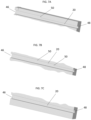
FIG. 7a shows an exemplary fluid pathway having an increasing cross-sectional area along a fluid pathway length; -
FIG. 7b shows an exemplary fluid pathway having an increasing cross-sectional area along a fluid pathway length; -
FIG. 7c shows an exemplary fluid pathway having an increasing cross-sectional area along a fluid pathway length;FIG. 8 shows an exemplary heat exchanger having an outlet with a larger cross-sectional area than the inlet; -
FIG. 9 shows an exemplary heat exchanger having an outlet with a larger cross-sectional area that the inlet; -
FIG. 10 shows an exemplary fluid pathway having a wavy plate disposed therein; -
FIG. 11 shows an exemplary fluid pathway having a wavy plate therein that includes a plurality of perforations; -
FIG. 12 shows an exemplary fluid pathway of a heat exchanger having vertically offset pathway portions; -
FIG. 13 illustrates the flow of fluid between vertically offset pathway portions, as shown inFIG. 12 ; and -
FIG. 14 shows an exemplary fluid pathway having one or more sharp corners. - A detailed description of one or more embodiments of the disclosed apparatus and method are presented herein by way of exemplification and not limitation with reference to the Figures.
- Illustrated in
FIG. 1 is an embodiment of apower electronics assembly 10. Thepower electronics assembly 10 includes one or morepower electronics devices 12 mounted to aheat exchanger 14 utilized to reject and dissipate thermal energy generated by thepower electronics devices 12 during operation. In some embodiments, thepower electronics devices 12 include a variable frequency drive (VFD) operably connected to acompressor 16 of a heating, ventilation, and air conditioning (HVAC)system 18. - Referring to
FIG. 2 , theHVAC system 18 includes, for example, avapor compression circuit 100 including thecompressor 16, acondenser 102, anexpansion device 104 and anevaporator 106 arranged in series and having a volume of refrigerant flowing therethrough. Thepower electronics assembly 10 is connected to thevapor compression circuit 100 such that a portion of the flow of liquid refrigerant exiting thecondenser 102 is diverted through theheat exchanger 14, bypassing theexpansion device 104 and is directed from theheat exchanger 14 to theevaporator 106. The liquid refrigerant from thecondenser 102 absorbs thermal energy generated by thepower electronics devices 12. This thermal energy generated by thepower electronics devices 12 may cause the refrigerant passing through theheat exchanger 14 to boil, changing phase of the refrigerant from liquid to vapor inside theheat exchanger 14. - Referring now to
FIG. 3 , anexemplary heat exchanger 14 is illustrated in more detail. As shown, theheat exchanger 14 includes a plurality of enclosedfluid pathways 20 extending therethrough, enabling a flow offluid 22 such as, for example, refrigerant, glycol, or water to flow therein. Thefluid pathways 20 extend between aheat exchanger inlet 26 through which the flow offluid 22 enters theheat exchanger 14, and aheat exchanger outlet 24 through which the flow offluid 22 exits theheat exchanger 14. In some embodiments, theheat exchanger outlet 24 is oriented vertically upwardly as shown to prevent vapor lock in theheat exchanger 14 flowpath under boiling condition. Theheat exchanger inlet 26 is connected to thefluid pathways 20 via aninlet manifold 30 to distribute the flow offluid 22 to thefluid pathways 20, and similarly theheat exchanger outlet 24 is connected to thefluid pathways 20 via anoutlet manifold 28. Immediately downstream of theinlet manifold 30,orifices 110 of different diameters, increasing with increasing distance from theheat exchanger inlet 26 are provided to distribute the flow offluid 22 from theinlet manifold 30 equally among all of thefluid pathways 20. The enhancement features described in the following text will be in thefluid pathways 20 downstream of therespective orifices 110. - In some embodiments, the
heat exchanger 14 is formed from a metal material, such as aluminum, aluminum alloy, steel, steel alloy, copper, copper alloy, or the like, and referring again toFIG. 1 , may be formed from two ormore plates plates fluid pathways 20, theinlet manifold 30, theoutlet manifold 28, theheat exchanger inlet 26 and/or theheat exchanger outlet 24 formed therein. The mating surfaces of theplates plates plates - In operation, the flow of
fluid 22, liquid refrigerant from thecondenser 102, enters theheat exchanger 14 at theheat exchanger inlet 26 and is distributed to thefluid pathways 20 via theinlet manifold 30. Theheat exchanger 14 conducts thermal energy from thepower electronics devices 12 and thermal energy is exchanged with the flow offluid 22 flowing through thefluid pathways 20, resulting in cooling of thepower electronics devices 12. The vapor flow offluid 22 is then collected at theoutlet manifold 28 and exits theheat exchanger 14 at theheat exchanger outlet 24. - The
heat exchanger 14 described herein includes one or more features, as will be described below, to improve heat transfer capacity of theheat exchanger 14 while reducing a pressure drop penalty of operation of theheat exchanger 14. While the features are described independently below, one skilled in the art will readily appreciate that the features may be incorporated into theheat exchanger 14 either independently or in combinations of two or more of the features to promote nucleate boiling heat transfer and to reduce pressure drop under two-phase flow condition while quality increases along the flow direction. The flow offluid 22 provided to theheat exchanger 14 is diverted from thecondenser 102 and in some embodiments enters theheat exchanger 14 in a liquid phase with 0% vapor quality or up to 20% vapor quality. The presently disclosedheat exchanger 14 may be operated to ensure the vapor quality of the flow offluid 22 exiting theheat exchanger 14 has a vapor quality of from about 25% to about 80%, or in another embodiment from about 40% to about 60%, or in yet another embodiment from about 45% to about 55%, or about 50%. The vapor quality change happens as the heat frompower electronics devices 12 is absorbed by the flow and used for phase change of the liquid refrigerant to vapor while travelling from theheat exchanger inlet 26 to theheat exchanger outlet 24. - Referring now to
FIG. 4 thefluid pathways 20 of theheat exchanger 14 may be formed to increase heat transfer area along aheat exchanger length 32. Thefluid pathways 20 may have a wavy shape along the heat exchanger length. In some embodiments, the wavy shape is a sinusoidal shape, but it is to be appreciated that other shapes may be utilized. In some embodiments, a peak-to-peak wavelength 34 of thefluid pathway 20 is in the range of 100 millimeters to 300 millimeters, while anamplitude 36 of the wave shape is in the range of 0.5 to 1.5 times apathway diameter 38 of thefluid pathway 20. The wave shape may extend along an entire length of thefluid pathway 20, while in some embodiments the wave shape may extend along only a portion of the length of thefluid pathway 20. While in the configuration ofFIG. 4 , the wavy shapes of adjacentfluid pathways 20 are in phase such that thefluid pathways 20 extend parallelly, in other embodiments such as shown inFIG. 4A the wavy shapes of the fluid pathways are out of phase, or opposed such that the flow area changes periodically along the length of theheat exchanger 14. - The
fluid pathways 20 may have heat transfer enhancement features formed therein. For example, as shown inFIG. 5 and 6 , thefluid pathways 20 may havenotches 40 or grooves formed in apathway wall 42 at anotch angle 44 relative to the direction of fluid flow through thefluid pathway 20. Thenotches 40 aid in spreading the flow offluid 22 along the Notches will help spreading the liquid along thepathway wall 42 thereby keeping thepathway wall 42 wet, and promoting nucleate boiling at thepathway wall 42. Further, thenotches 40 promote turbulence in the flow offluid 22 to increase mixing of the flow offluid 22. In some embodiments thenotches 40 extend unbroken around an entire circumference of thefluid pathway 20, while in other embodiments thenotches 40 are segmented and extend only a selected circumferential angle around thefluid pathway 20. In some embodiments, anotch depth 60 is in the range of 300-700 micron. Anotch width 62 may be in the range of 200-2000 micron, while anotch pitch 64 betweenadjacent notches 40 may be in the range of 400-5000 microns. In some embodiments, thenotch angle 44 is between 30 degrees and 60 degrees. While in the embodiments illustrated herein thenotches 40 have a rectangular shape, other shapes such a triangular to semicircular, for example, may be utilized. - Referring now to
FIGs. 7a-7c , thefluid pathways 20 may have an increasing cross-sectional area, such that an outletcross-sectional area 46 at theoutlet manifold 30 is greater than an inletcross-sectional area 48 at theinlet manifold 28. The change in cross-sectional area may be achieved by one ormore steps 50 formed in the fluid pathway as inFIG. 7a and 7b , or alternatively may be a gradual, continuous increase in area as illustrated inFIG. 7c . The area change will help in reducing the pressure drop in thefluid pathways 20 as volume of vapor flow under two-phase condition increases from inlet to outlet. - Referring now to
FIG. 8 and 9 , theoutlet manifold 28 may be sized relative to theinlet manifold 30 to account for the increased vapor volume at theoutlet manifold 28. For example, theoutlet manifold 28 may have a largerhydraulic diameter 52 than the inlet manifoldhydraulic diameter 54. Similarly, theheat exchanger outlet 24 may be sized to have a larger flow area than theheat exchanger inlet 26 to similarly account for the increased vapor volume under two-phase condition at theheat exchanger outlet 24 to reduce the pressure drop along theheat exchanger 26. - Referring now to
FIG. 10 , in some embodiments awavy plate 66 is disposed in thefluid pathway 20 extending partially across apathway height 68. In some embodiments, thewavy plate 66 extends between 25 and 75 percent across thepathway height 68. In some embodiments thewavy plate 66 has aplate thickness 70 between 0.1-0.5 millimeters. Thewavy plate 66 may have aplate wavelength 72 between 50-200 millimeters, and/or aplate amplitude 74 between about 10 percent and 40 percent of thepathway height 68 i.e covering 20 to 80% of the pathway height. Thewavy plate 66 increases turbulence and mixing of the flow offluid 22 in thefluid pathway 20. Thewavy plate 70 can either cover the partial length of thepathway 20 or the entire length of thepathway 20. In addition, thewavy plate 66 can be installed perpendicular to face 68 (vertical face) or it can be inclined at an angle 45-90 deg. This would help draining of the liquid towards the heated wall, so it will keep the wall wet and enhance nucleate boiling. Also, the meniscus formed at the junction of the waveplate and trough of the wave would assist in thin film evaporation. - Referring now to
FIG. 11 , in some embodiments thewavy plate 66 extends entirely across thepathway height 68 and includes a plurality ofperforations 76 formed therein. In some embodiments, theperforations 76 are between 0.5 millimeters and 2 millimeters in diameter. Thewavy plate 66 may be configured such that an open area for the flow offluid 22 throughwavy plate 66 increases along the flow direction of the flow offluid 22 along thefluid pathway 20. This may be accomplished by increasing the number ofperforations 76 and/or increasing the size of theperforations 76. The area change will help in reducing the pressure drop in thefluid pathway 20 as volume of vapor flow increases from inlet to outlet under two-phase boiling condition. More (i.e. an increased number of)perforations 76 also results in higher heat transfer area and improves the heat transfer performance. In addition, to manage the pressure drop, the number ofperforations 76 near the entrance of thefluid pathway 20 can be increased and relative to that flow area must increase along the length. Thewavy plate 66 can either cover the partial length of thefluid pathway 20 or the entire length of thefluid pathway 20. This would help reduce the pressure drop resistance. - As shown in
FIG. 12 , in aheat exchanger 14 having a twoplate plate fluid pathway 20 formed therein. Afirst pathway portion 78 formed in thefirst plate 32 may be offset in a vertical direction relative to asecond pathway portion 80 formed in thesecond plate 34. The offset of thefirst pathway portion 78 and thesecond pathway portion 80 may be between 20 percent and 70 percent of thepathway height 68, and may be biased such that thefirst plate 32 has thepower electronics devices 12 mounted thereto, and thefirst pathway portions 78 are vertically lower than thesecond pathway portions 80. This arrangement aids in directing the flow of liquid into thefirst pathway portions 78 closer to thepower electronics devices 12 as shown inFIG. 13 , so the vapor is pushed away from theportion 78 toportion 80, thereby improving heat transfer effectiveness by increasing nucleate boiling in thefirst pathway 78 and also preventing thefirst pathway portions 78 from drying out. Further, thefluid pathways 20 may be provided with additional two or more corners as shown inFIG. 14 to promote thin film evaporation when the flow will be transitioned to annular flow. The corners of thefluid pathways 20 will have a liquid meniscus that will promote thin film evaporation. - The enhanced features of the
heat exchanger 14 as disclosed herein promote convective flow boiling for high heat transfer rate, reduced pressure drop and improved compactness of theheat exchanger 14. - The term "about" is intended to include the degree of error associated with measurement of the particular quantity based upon the equipment available at the time of filing the application.
- The terminology used herein is for the purpose of describing particular embodiments only and is not intended to be limiting of the present invention. As used herein, the singular forms "a", "an" and "the" are intended to include the plural forms as well, unless the context clearly indicates otherwise. It will be further understood that the terms "comprises" and/or "comprising," when used in this specification, specify the presence of stated features, integers, steps, operations, elements, and/or components, but do not preclude the presence or addition of one or more other features, integers, steps, operations, element components, and/or groups thereof.
- While the present invention has been described with reference to an exemplary embodiment or embodiments, it will be understood by those skilled in the art that various changes may be made and equivalents may be substituted for elements thereof without departing from the scope of the present invention. In addition, many modifications may be made to adapt a particular situation or material to the teachings of the present invention without departing from the essential scope thereof. Therefore, it is intended that the present invention not be limited to the particular embodiment disclosed as a best mode contemplated for carrying out this present invention, but that the present invention will include all embodiments falling within the scope of the claims.
Claims (15)
- A power electronics assembly (10), comprising:one or more power electronics devices (12); anda heat exchanger (14) to which the one or more power electronics devices (12) are mounted, the heat exchanger comprising (14):an inlet manifold (30) and an outlet manifold (28); andone or more fluid pathways (20) extending connecting the inlet manifold (30) and the outlet manifold (28), the heat exchanger (14) configured to transfer thermal energy from the one or more power electronics devices (12) into a flow of fluid (22) passing through the one or more fluid pathways (20);wherein the one or more fluid pathways (20) include one or more internal enhancements (40) and channel configurations to enhance thermal energy transfer by promoting boiling of the flow of fluid (22) and to reduce the pressure drop in the pathways (20) under a two-phase flow condition;wherein the flow of fluid (22) is a flow of liquid refrigerant diverted from a condenser (102) of a heating, ventilation, and air conditioning (HVAC) system (18).
- The power electronics assembly (10) of claim 1, wherein the one or more fluid pathways (20) have a wavy shape along a length (32) of the one or more fluid pathways (20).
- The power electronics assembly (10) of claim 1 or 2, wherein the one or more internal enhancements include one or more inclined notches (40) formed in the one or more fluid pathways (20);
wherein the (each) notch (40) is optionally oriented at a notch angle of between 30 and 60 degrees relative to the flow of fluid (22) through the one or more fluid pathways (20). - The power electronics assembly (10) of any preceding claim, wherein a cross-sectional area (46) of the one or more fluid pathways (20) increases along the flow direction of the flow of fluid (22) from the pathway inlet (30) to a pathway outlet (28).
- The power electronics assembly (10) of any preceding claim, wherein a heat exchanger outlet (24) has a larger cross-sectional area than a heat exchanger inlet (26).
- The power electronics assembly (10) of any preceding claim, further comprising a wavy plate (66) disposed in the (each) fluid pathway (20) extending at least partially across the fluid pathway (20).
- The power electronics assembly (10) of claim 6, wherein the wavy plate (66) includes a plurality of perforations (76) along at least a partial length of the fluid pathway (20);
wherein optionally one or more of a perforation (76) number or a perforation (76) size increases from a fluid pathway inlet (30) to a fluid pathway outlet (28) by reducing the flow restrictions along the flow direction of the flow of fluid under the two-phase flow condition. - The power electronics assembly (10) of any preceding claim, wherein the heat exchanger (14) is formed from a first plate (32) including a first pathway portion (78) of the one or more fluid pathways (20) and a second plate (34) including a second pathway portion (80) of the one or more fluid pathways (20);
wherein the first pathway portion (78) is optionally vertically offset from the second pathway portion (80). - A method of cooling one or more power electronics devices (12), comprising:securing the one or more power electronics devices (12) to a heat exchanger (14), the heat exchanger (14) comprising one or more fluid pathways (20);circulating a flow of fluid (22) through one or more fluid pathways (20) to transfer thermal energy from the one or more power electronics devices (12) to the flow of fluid (22) passing through the one or more fluid pathways (20);wherein the one or more fluid pathways (20) include one or more internal enhancements (40) and channel design to enhance thermal energy transfer by promoting boiling of the flow of fluid (22) and to reduce the pressure drop in the pathways (20) under two-phase flow condition;wherein the flow of fluid (22) is a flow of liquid refrigerant diverted from a condenser (102) of a heating, ventilation, and air conditioning (HVAC) system (18).
- The method of claim 9, wherein the one or more fluid pathways (20) have a wavy shape along a length (32) of the one or more fluid pathways (20).
- The method of claim 9 or 10, wherein the one or more internal enhancements include one or more notches (40) formed in the one or more fluid pathways (20), the one or more notches (40) oriented at a notch angle of between 30 and 60 degrees relative to the flow of fluid (22) through the one or more fluid pathways (20).
- The method of claim 9, 10 or 11, wherein a cross-sectional area (46) of the one or more fluid pathways increases from a pathway inlet (30) to a pathway outlet (28);
and/or wherein a heat exchanger outlet (24) has a greater cross-sectional area than a heat exchanger inlet (26). - The method of any of claims 9 to 12, further comprising a wavy plate (66) disposed in the (each) fluid pathway (20).
- The method of claim 13, wherein the wavy plate (66) includes a plurality of perforations (76);
wherein one or more of a perforation (76) number or a perforation (76) size optionally increases from a fluid pathway inlet (30) to a fluid pathway outlet (28). - The method of any of claims 9 to 14, wherein:the heat exchanger (14) is formed from a first plate (32) including a first pathway portion (78) of the one or more fluid pathways (20) and a second plate (34) including a second pathway portion (80) of the one or more fluid pathways (20); andthe first pathway portion (78) is vertically offset from the second pathway portion (80).
Applications Claiming Priority (1)
| Application Number | Priority Date | Filing Date | Title |
|---|---|---|---|
| US202163272298P | 2021-10-27 | 2021-10-27 |
Publications (1)
| Publication Number | Publication Date |
|---|---|
| EP4174432A1 true EP4174432A1 (en) | 2023-05-03 |
Family
ID=84044769
Family Applications (1)
| Application Number | Title | Priority Date | Filing Date |
|---|---|---|---|
| EP22204232.7A Pending EP4174432A1 (en) | 2021-10-27 | 2022-10-27 | Enhanced channel configuration for heat exchanger to cool power electronics |
Country Status (3)
| Country | Link |
|---|---|
| US (1) | US20230126158A1 (en) |
| EP (1) | EP4174432A1 (en) |
| CN (1) | CN116033706A (en) |
Citations (8)
| Publication number | Priority date | Publication date | Assignee | Title |
|---|---|---|---|---|
| US5002123A (en) * | 1989-04-20 | 1991-03-26 | Microelectronics And Computer Technology Corporation | Low pressure high heat transfer fluid heat exchanger |
| US20090302458A1 (en) * | 2005-06-27 | 2009-12-10 | Hidehito Kubo | Heat Sink For Power Module |
| US20110079376A1 (en) * | 2009-10-03 | 2011-04-07 | Wolverine Tube, Inc. | Cold plate with pins |
| US20130056176A1 (en) * | 2011-08-26 | 2013-03-07 | Mikros Manufacturing, Inc. | Heat Exchanger with Controlled Coefficient of Thermal Expansion |
| US20140158324A1 (en) * | 2012-12-07 | 2014-06-12 | Mitsubishi Electric Corporation | Cooling apparatus |
| CN104465562A (en) * | 2014-12-24 | 2015-03-25 | 西安电子科技大学 | Chain type staggered micro-channel structure |
| US20170064866A1 (en) * | 2015-08-28 | 2017-03-02 | National Chiao Tung University | Heat conducting module |
| CN108225079A (en) * | 2017-12-26 | 2018-06-29 | 华北电力大学 | A kind of non-homogeneous wetability silicon substrate microchannel phase-change heat-exchanger of top unicom |
-
2022
- 2022-10-20 US US18/048,237 patent/US20230126158A1/en active Pending
- 2022-10-26 CN CN202211317000.5A patent/CN116033706A/en active Pending
- 2022-10-27 EP EP22204232.7A patent/EP4174432A1/en active Pending
Patent Citations (8)
| Publication number | Priority date | Publication date | Assignee | Title |
|---|---|---|---|---|
| US5002123A (en) * | 1989-04-20 | 1991-03-26 | Microelectronics And Computer Technology Corporation | Low pressure high heat transfer fluid heat exchanger |
| US20090302458A1 (en) * | 2005-06-27 | 2009-12-10 | Hidehito Kubo | Heat Sink For Power Module |
| US20110079376A1 (en) * | 2009-10-03 | 2011-04-07 | Wolverine Tube, Inc. | Cold plate with pins |
| US20130056176A1 (en) * | 2011-08-26 | 2013-03-07 | Mikros Manufacturing, Inc. | Heat Exchanger with Controlled Coefficient of Thermal Expansion |
| US20140158324A1 (en) * | 2012-12-07 | 2014-06-12 | Mitsubishi Electric Corporation | Cooling apparatus |
| CN104465562A (en) * | 2014-12-24 | 2015-03-25 | 西安电子科技大学 | Chain type staggered micro-channel structure |
| US20170064866A1 (en) * | 2015-08-28 | 2017-03-02 | National Chiao Tung University | Heat conducting module |
| CN108225079A (en) * | 2017-12-26 | 2018-06-29 | 华北电力大学 | A kind of non-homogeneous wetability silicon substrate microchannel phase-change heat-exchanger of top unicom |
Also Published As
| Publication number | Publication date |
|---|---|
| CN116033706A (en) | 2023-04-28 |
| US20230126158A1 (en) | 2023-04-27 |
Similar Documents
| Publication | Publication Date | Title |
|---|---|---|
| US8061416B2 (en) | Heat exchanger and method for the production thereof | |
| US6725912B1 (en) | Wind tunnel and heat exchanger therefor | |
| US20160003546A1 (en) | Multichannel heat exchanger tubes with flow path inlet sections | |
| US3916644A (en) | Dehumidifier with a plate-type evaporator | |
| EP1809971A2 (en) | Parallel flow evaporator with non-uniform characteristics | |
| WO2022166224A1 (en) | Heat exchanger, electric control box and air conditioning system | |
| RU2731464C2 (en) | Heat exchanger comprising a device for distribution of liquid-gas mixture | |
| WO2008024066A1 (en) | Plate heat exchanger and heat exchanger plant | |
| US20210404750A1 (en) | Integrated hybrid compact fluid heat exchanger | |
| WO2022166237A1 (en) | Electric control box and air conditioning system | |
| EP4174432A1 (en) | Enhanced channel configuration for heat exchanger to cool power electronics | |
| JP3911604B2 (en) | Heat exchanger and refrigeration cycle | |
| EP4174433A1 (en) | Heat exchanger for power electronics | |
| WO2022166238A1 (en) | Air conditioning system | |
| EP4175434A1 (en) | Combined liquid and air cooled power electronics assembly | |
| JP2001304719A (en) | Module type multi-channel flat pipe evaporator | |
| EP4175435A1 (en) | Mechanically expanded microfin tube liquid cooled heat sink | |
| JPH07294179A (en) | Heat exchanging device | |
| CN102022869A (en) | Oblate tube heat exchanger structure | |
| US7650934B2 (en) | Heat exchanger | |
| WO2000071956A1 (en) | Wind tunnel and heat exchanger therefor | |
| KR20020002777A (en) | Heat exchanger with over saturation coolant by pass function | |
| CN218920815U (en) | Radiator and variable frequency air conditioning system | |
| US20220373236A1 (en) | Heat exchanger for power electronics | |
| EP4175436A1 (en) | Refrigerant cooled heat sink for power electronic modules |
Legal Events
| Date | Code | Title | Description |
|---|---|---|---|
| PUAI | Public reference made under article 153(3) epc to a published international application that has entered the european phase |
Free format text: ORIGINAL CODE: 0009012 |
|
| STAA | Information on the status of an ep patent application or granted ep patent |
Free format text: STATUS: THE APPLICATION HAS BEEN PUBLISHED |
|
| AK | Designated contracting states |
Kind code of ref document: A1 Designated state(s): AL AT BE BG CH CY CZ DE DK EE ES FI FR GB GR HR HU IE IS IT LI LT LU LV MC ME MK MT NL NO PL PT RO RS SE SI SK SM TR |
|
| P01 | Opt-out of the competence of the unified patent court (upc) registered |
Effective date: 20230527 |
|
| STAA | Information on the status of an ep patent application or granted ep patent |
Free format text: STATUS: REQUEST FOR EXAMINATION WAS MADE |
|
| 17P | Request for examination filed |
Effective date: 20231103 |
|
| RBV | Designated contracting states (corrected) |
Designated state(s): AL AT BE BG CH CY CZ DE DK EE ES FI FR GB GR HR HU IE IS IT LI LT LU LV MC ME MK MT NL NO PL PT RO RS SE SI SK SM TR |
|
| STAA | Information on the status of an ep patent application or granted ep patent |
Free format text: STATUS: EXAMINATION IS IN PROGRESS |
|
| 17Q | First examination report despatched |
Effective date: 20240314 |