EP4173874A1 - Valve device for a system, in particular for a vehicle, and system, in particular brake system for a vehicle - Google Patents
Valve device for a system, in particular for a vehicle, and system, in particular brake system for a vehicle Download PDFInfo
- Publication number
- EP4173874A1 EP4173874A1 EP22203254.2A EP22203254A EP4173874A1 EP 4173874 A1 EP4173874 A1 EP 4173874A1 EP 22203254 A EP22203254 A EP 22203254A EP 4173874 A1 EP4173874 A1 EP 4173874A1
- Authority
- EP
- European Patent Office
- Prior art keywords
- connection
- supply
- electrical
- valve
- terminal
- Prior art date
- Legal status (The legal status is an assumption and is not a legal conclusion. Google has not performed a legal analysis and makes no representation as to the accuracy of the status listed.)
- Pending
Links
- 230000001681 protective effect Effects 0.000 claims abstract description 31
- 230000007797 corrosion Effects 0.000 claims description 4
- 238000005260 corrosion Methods 0.000 claims description 4
- 230000009970 fire resistant effect Effects 0.000 claims description 2
- 101100489713 Saccharomyces cerevisiae (strain ATCC 204508 / S288c) GND1 gene Proteins 0.000 description 3
- 230000004913 activation Effects 0.000 description 2
- 238000010586 diagram Methods 0.000 description 2
- 230000009977 dual effect Effects 0.000 description 2
- 238000009434 installation Methods 0.000 description 2
- 230000007547 defect Effects 0.000 description 1
- 230000010354 integration Effects 0.000 description 1
- 239000004065 semiconductor Substances 0.000 description 1
- 239000013589 supplement Substances 0.000 description 1
Images

Classifications
-
- B—PERFORMING OPERATIONS; TRANSPORTING
- B60—VEHICLES IN GENERAL
- B60T—VEHICLE BRAKE CONTROL SYSTEMS OR PARTS THEREOF; BRAKE CONTROL SYSTEMS OR PARTS THEREOF, IN GENERAL; ARRANGEMENT OF BRAKING ELEMENTS ON VEHICLES IN GENERAL; PORTABLE DEVICES FOR PREVENTING UNWANTED MOVEMENT OF VEHICLES; VEHICLE MODIFICATIONS TO FACILITATE COOLING OF BRAKES
- B60T13/00—Transmitting braking action from initiating means to ultimate brake actuator with power assistance or drive; Brake systems incorporating such transmitting means, e.g. air-pressure brake systems
- B60T13/10—Transmitting braking action from initiating means to ultimate brake actuator with power assistance or drive; Brake systems incorporating such transmitting means, e.g. air-pressure brake systems with fluid assistance, drive, or release
- B60T13/66—Electrical control in fluid-pressure brake systems
- B60T13/68—Electrical control in fluid-pressure brake systems by electrically-controlled valves
- B60T13/683—Electrical control in fluid-pressure brake systems by electrically-controlled valves in pneumatic systems or parts thereof
-
- B—PERFORMING OPERATIONS; TRANSPORTING
- B60—VEHICLES IN GENERAL
- B60T—VEHICLE BRAKE CONTROL SYSTEMS OR PARTS THEREOF; BRAKE CONTROL SYSTEMS OR PARTS THEREOF, IN GENERAL; ARRANGEMENT OF BRAKING ELEMENTS ON VEHICLES IN GENERAL; PORTABLE DEVICES FOR PREVENTING UNWANTED MOVEMENT OF VEHICLES; VEHICLE MODIFICATIONS TO FACILITATE COOLING OF BRAKES
- B60T17/00—Component parts, details, or accessories of power brake systems not covered by groups B60T8/00, B60T13/00 or B60T15/00, or presenting other characteristic features
-
- B—PERFORMING OPERATIONS; TRANSPORTING
- B60—VEHICLES IN GENERAL
- B60T—VEHICLE BRAKE CONTROL SYSTEMS OR PARTS THEREOF; BRAKE CONTROL SYSTEMS OR PARTS THEREOF, IN GENERAL; ARRANGEMENT OF BRAKING ELEMENTS ON VEHICLES IN GENERAL; PORTABLE DEVICES FOR PREVENTING UNWANTED MOVEMENT OF VEHICLES; VEHICLE MODIFICATIONS TO FACILITATE COOLING OF BRAKES
- B60T15/00—Construction arrangement, or operation of valves incorporated in power brake systems and not covered by groups B60T11/00 or B60T13/00
- B60T15/02—Application and release valves
- B60T15/025—Electrically controlled valves
- B60T15/027—Electrically controlled valves in pneumatic systems
-
- G—PHYSICS
- G05—CONTROLLING; REGULATING
- G05D—SYSTEMS FOR CONTROLLING OR REGULATING NON-ELECTRIC VARIABLES
- G05D16/00—Control of fluid pressure
- G05D16/20—Control of fluid pressure characterised by the use of electric means
- G05D16/2006—Control of fluid pressure characterised by the use of electric means with direct action of electric energy on controlling means
- G05D16/2013—Control of fluid pressure characterised by the use of electric means with direct action of electric energy on controlling means using throttling means as controlling means
-
- H—ELECTRICITY
- H02—GENERATION; CONVERSION OR DISTRIBUTION OF ELECTRIC POWER
- H02H—EMERGENCY PROTECTIVE CIRCUIT ARRANGEMENTS
- H02H3/00—Emergency protective circuit arrangements for automatic disconnection directly responsive to an undesired change from normal electric working condition with or without subsequent reconnection ; integrated protection
- H02H3/08—Emergency protective circuit arrangements for automatic disconnection directly responsive to an undesired change from normal electric working condition with or without subsequent reconnection ; integrated protection responsive to excess current
-
- B—PERFORMING OPERATIONS; TRANSPORTING
- B60—VEHICLES IN GENERAL
- B60T—VEHICLE BRAKE CONTROL SYSTEMS OR PARTS THEREOF; BRAKE CONTROL SYSTEMS OR PARTS THEREOF, IN GENERAL; ARRANGEMENT OF BRAKING ELEMENTS ON VEHICLES IN GENERAL; PORTABLE DEVICES FOR PREVENTING UNWANTED MOVEMENT OF VEHICLES; VEHICLE MODIFICATIONS TO FACILITATE COOLING OF BRAKES
- B60T2270/00—Further aspects of brake control systems not otherwise provided for
- B60T2270/40—Failsafe aspects of brake control systems
- B60T2270/402—Back-up
-
- B—PERFORMING OPERATIONS; TRANSPORTING
- B60—VEHICLES IN GENERAL
- B60T—VEHICLE BRAKE CONTROL SYSTEMS OR PARTS THEREOF; BRAKE CONTROL SYSTEMS OR PARTS THEREOF, IN GENERAL; ARRANGEMENT OF BRAKING ELEMENTS ON VEHICLES IN GENERAL; PORTABLE DEVICES FOR PREVENTING UNWANTED MOVEMENT OF VEHICLES; VEHICLE MODIFICATIONS TO FACILITATE COOLING OF BRAKES
- B60T2270/00—Further aspects of brake control systems not otherwise provided for
- B60T2270/40—Failsafe aspects of brake control systems
- B60T2270/413—Plausibility monitoring, cross check, redundancy
-
- B—PERFORMING OPERATIONS; TRANSPORTING
- B60—VEHICLES IN GENERAL
- B60T—VEHICLE BRAKE CONTROL SYSTEMS OR PARTS THEREOF; BRAKE CONTROL SYSTEMS OR PARTS THEREOF, IN GENERAL; ARRANGEMENT OF BRAKING ELEMENTS ON VEHICLES IN GENERAL; PORTABLE DEVICES FOR PREVENTING UNWANTED MOVEMENT OF VEHICLES; VEHICLE MODIFICATIONS TO FACILITATE COOLING OF BRAKES
- B60T2270/00—Further aspects of brake control systems not otherwise provided for
- B60T2270/40—Failsafe aspects of brake control systems
- B60T2270/415—Short-circuit, open circuit failure
-
- B—PERFORMING OPERATIONS; TRANSPORTING
- B60—VEHICLES IN GENERAL
- B60T—VEHICLE BRAKE CONTROL SYSTEMS OR PARTS THEREOF; BRAKE CONTROL SYSTEMS OR PARTS THEREOF, IN GENERAL; ARRANGEMENT OF BRAKING ELEMENTS ON VEHICLES IN GENERAL; PORTABLE DEVICES FOR PREVENTING UNWANTED MOVEMENT OF VEHICLES; VEHICLE MODIFICATIONS TO FACILITATE COOLING OF BRAKES
- B60T2270/00—Further aspects of brake control systems not otherwise provided for
- B60T2270/84—Driver circuits for actuating motor, valve and the like
-
- H—ELECTRICITY
- H02—GENERATION; CONVERSION OR DISTRIBUTION OF ELECTRIC POWER
- H02J—CIRCUIT ARRANGEMENTS OR SYSTEMS FOR SUPPLYING OR DISTRIBUTING ELECTRIC POWER; SYSTEMS FOR STORING ELECTRIC ENERGY
- H02J1/00—Circuit arrangements for dc mains or dc distribution networks
- H02J1/08—Three-wire systems; Systems having more than three wires
- H02J1/082—Plural DC voltage, e.g. DC supply voltage with at least two different DC voltage levels
-
- H—ELECTRICITY
- H02—GENERATION; CONVERSION OR DISTRIBUTION OF ELECTRIC POWER
- H02J—CIRCUIT ARRANGEMENTS OR SYSTEMS FOR SUPPLYING OR DISTRIBUTING ELECTRIC POWER; SYSTEMS FOR STORING ELECTRIC ENERGY
- H02J2310/00—The network for supplying or distributing electric power characterised by its spatial reach or by the load
- H02J2310/40—The network being an on-board power network, i.e. within a vehicle
Definitions
- the present invention relates to a valve device for a system, in particular a braking system for a vehicle, and to a system or braking system for a vehicle, in particular an electronic braking system.
- redundancies have to be created.
- these redundancies are to be designed in such a way that the vehicle cannot reach a safety-critical or uncontrollable state.
- systems such as the electric braking system EBS or ABS are being installed multiple times in the vehicle.
- Another possibility can be to supplement the system with similar subsystems that can map the functionality.
- the faulty system can be switched off and the second error-free system can take over the task and thus create redundancy.
- a number of pressure control valves on each axle or a respective wheel would be doubled.
- an error protection module for a pressure control valve can be provided, for example for dual use or multiple use for a vehicle brake system to be designed redundantly.
- electrical protection circuits each having an electrical Include safety device and a diode element to be integrated into a separate error protection module of the pressure control valve.
- a pressure control valve can be used by two control units in an electrically protected manner by means of the safety devices, in order to provide redundancy in the brake system.
- a cost-effective multiple system can be provided, with it being possible to avoid duplicating pressure control valves.
- Integrating the protective circuits at least one of which is designed as a combination of at least one fuse and/or at least one diode, for example, in a valve, in particular a pressure control valve, has the advantage that vehicle wiring is made easier for dual use.
- Y-cables which can be susceptible to corrosion, can be dispensed with. It is possible to adapt the pressure control valve or, to be more precise, the error protection module in a simple manner using suitable plug connections. Furthermore, corrosion on electrical connections can be minimized or prevented, in particular via such an external module.
- the arrangement of the safety devices in the separate fault protection module or separate from the valve unit, which can be positioned relative to the valve unit depending on the requirements, is particularly advantageous, with a distance between the valve unit and the fault protection module being able to be selected in a suitable manner.
- the separate error protection module is also advantageous because installation space near the valve unit in a vehicle can be limited because the valve device can be positioned near the axle or near the wheel.
- a new development of pressure control valves with integrated fuses and diodes can be avoided.
- the valve unit of the valve device can be exchanged or varied independently of the error protection module.
- the vehicle can be a motor vehicle, in particular a commercial vehicle, for example a truck or the like.
- the system can be used as an electronic braking system or electro-pneumatic Brake system be running.
- the first controller may be a primary controller, and the second controller may be a redundant controller.
- the first control unit can be assigned to a first function or assistance function of the vehicle or the brake system, and the second control unit can be assigned to a second function or assistance function of the vehicle or the brake system.
- the device can be designed as a pressure control valve.
- the valve unit and thus the valve device can have at least one solenoid valve.
- the actuator may include a resistive inductor.
- the diode element may include a diode, a semiconductor diode, or the like.
- the safety device can have a fuse or other electrical fuse, for example a self-resetting fuse or a multiple fuse. In this case, the error protection module can be arranged adjacent to or adjacent to the valve unit in order to prevent the connection terminals
- the actuator can be connected to a first electrical supply potential of the first control device via the first supply connection and the first connection connection.
- the actuator can be connected to a second electrical supply potential of the second control unit via the second supply connection and the first connection connection.
- the actuator can be connected to a common electrical ground potential of the control units via the second connection connection and the first main connection or via the second connection connection and the second main connection.
- the safety device of the first protection circuit can also be connected between the first supply connection and the first connection connection.
- the diode element of the first protection circuit can be connected between the second supply terminal and the first connection terminal.
- the safety device of the second protection circuit between the second Connection port and the first main port to be connected.
- the diode element of the second protection circuit may be connected between the second connection terminal and the second main terminal.
- a conducting direction of the diode element of the first protection circuit can run from the second supply connection to the first connection connection.
- a forward direction of the diode element of the second protection circuit can run from the second connection terminal to the second main terminal.
- valve unit can have at least one further actuator for actuating the valve unit.
- the second connection terminal of the error protection module can be electrically connectable or connected to the further actuator.
- the fault protection module can have at least one third supply connection for the electrical connection to the first control unit, at least one fourth supply connection for the electrical connection to the second control unit, at least one further connection connection which is electrically connected to the third supply connection and the fourth supply connection for the electrical connection to the further actuator and at least have another protective circuit.
- the further protection circuit can be connected electrically between the third supply connection and the fourth supply connection on the one hand and the further connection connection on the other hand.
- the actuator of the valve unit can be part of an inlet valve of the valve device, for example, and the further actuator can be part of an outlet valve of the valve device, for example.
- Such an embodiment offers the advantage that any number of actuators of the valve device can be secured with minimal effort.
- the safety device of the further protective circuit can be connected between the third supply connection and the further connection connection.
- the diode element of the further protection circuit can be connected between the fourth supply connection and the further connection connection.
- a conducting direction of the diode element of the further protection circuit can run from the fourth supply connection to the first connection connection.
- the further actuator can be connected to the first electrical supply potential via the third supply connection and the further connection connection.
- the additional actuator can be connected to the second electrical supply potential via the fourth supply connection and the additional connection connection.
- the error protection module can be designed to be exchangeable. Such an embodiment offers the advantage that, after an error has occurred, a safety device or several safety devices can be easily replaced in order to restore the functionality of the error protection module.
- the safety devices of the protective circuits can also be arranged in the protective circuits so that they can be replaced. Additionally or alternatively, at least one of the protective circuits can be exchangeable. Such an embodiment offers the advantage that after a fault has occurred, a safety device or several safety devices or an entire protective circuit can be replaced inexpensively in order to restore the functionality of the protective circuits.
- valve device can have cut-resistant, fire-resistant and/or corrosion-resistant cables for connecting the valve unit and the fault protection module to one another.
- the valve device can be or can be connected to the first control device and to the second control device by means of electrical lines.
- the braking system can also have at least one further valve device.
- FIG. 1 shows a schematic representation of a braking system 100 as a system.
- the first control unit ECU1 includes connections PCV1_IV, PCV1_OV, PCV2_IV, PCV2_OV and GVR1 for electrical connection to actuators 110 and connections UB1 and GND1 for connection to a first electrical voltage source.
- the second control device ECU2 includes connections PCV1_IV, PCV1_OV, PCV2_IV, PCV2_OV and GVR1 for the electrical connection to the actuators 110 and connections UB2 and GND1 for connection to a second electrical voltage source.
- a short circuit from UB1 to the jointly used actuator ground is also shown as an example.
- a state can arise in which neither the first control unit ECU1 nor the second control unit ECU2 can control the actuators 110 .
- activation is no longer possible.
- Another possible error case is the end of the control after UB1 or UB2.
- ABS control for example, is therefore not possible in this case of error either from the first control unit ECU1 or from the second control unit ECU2.
- a redundancy of a primary brake system is therefore not given under certain circumstances.
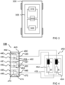
- FIG. 2 shows a schematic representation of a braking system 200 as a system.
- the braking system 200 in 2 corresponds to the braking system 1 with the exception of the fact that only one pressure control valve with two actuators 210 is provided, with a fuse F and a diode D also being provided to protect the pressure control valve.
- Several electronic control units here the first control unit ECU1 and the second control unit ECU2, use a common pressure control valve for brake control, which has the two actuators 210 in order to provide redundancy in the brake system 200 .
- the fuse F should blow and thus separate the ground line GVR1, which has a short circuit.
- the diode D is intended to provide protection in the event of a short circuit in UB1 on the second control unit side of ECU2.
- FIG. 3 shows a schematic representation of a vehicle 300 with a braking system 305 as a system according to an embodiment.
- the braking system 305 can be the braking system 2 resemble Brake system 305 includes a first control unit 310, a second control unit 320 and a valve device 330.
- Control units 310 and 320 are electrically connected to valve device 330.
- the valve device 330 will be discussed in more detail below.
- FIG 4 shows a schematic representation of an embodiment of a valve device 330 for a braking system as a system.
- the braking system corresponds to or resembles the braking system 3 .
- the braking system thus comprises a first control unit and a second control unit which can be or are electrically connected to the valve device 330 .
- the valve device 330 corresponds or is similar to the valve device in FIG 3 .
- the valve device 330 is embodied as a pressure control valve (PCV) for the brake system.
- PCV pressure control valve
- the valve device 330 includes an error protection module 440, a valve unit 450 and a valve housing 435.
- the valve housing 435 is shaped to accommodate the valve unit 450.
- the valve unit 450 is designed to set a pressure of a working medium for the brake system.
- the valve unit 450 includes at least one actuator 452 for actuating the valve unit 450.
- the valve unit 450 is arranged within the valve housing 435.
- the at least one actuator 452 includes a resistive inductor as shown in FIG 4 is illustrated by an equivalent circuit diagram with an inductance L and a resistance R.
- the error protection module 440 is arranged outside of the valve housing 435 .
- the fault protection module 440 comprises a first supply connection 441, a second supply connection 442, a first main connection 445, a second main connection 446, a first connection connection 447, a second connection connection 448, a first electrical protection circuit 460 and a second electrical protection circuit 470.
- the first supply connection 441 is used for the electrical connection to the first control unit of the brake system.
- the second supply connection 442 is used for the electrical connection to the second control unit of the brake system.
- the first main connection 445 is used for the electrical connection to the first control device.
- the second main connection 446 is used for the electrical connection to the second control device.
- the first connection terminal 447 is electrically connected to the first supply connection 441 and the second supply connection 442 and is used for electrical connection with the actuator 452.
- the second connection terminal 448 is electrically connected with the first main connection 445 and the second main connection 446 and is used for electrical connection with the actuator 452.
- the first protection circuit 460 is electrically connected between the first supply terminal 441 and the second supply terminal 442 on the one hand and the first connection terminal 447 on the other hand.
- the first protective circuit 460 comprises an electrical safety device 462 and a diode element 464 which are connected in series with the respective supply/main connection.
- the second protection circuit 470 is electrically connected between the second connection terminal 448 on the one hand and the first main terminal 445 and the second main terminal 446 on the other hand.
- the second protective circuit 470 comprises an electrical safety device 472 and a diode element 474 which are connected in series with the respective supply/main connection.
- safety devices 462 and 472 are designed to trigger in the event of an electrical error in the brake system, for example in the event of a short circuit, and to prevent the error.
- the diode elements 464 and 474 are designed to also prevent impermissible current flow in such a fault situation.
- the safety device 462 of the first protection circuit 460 is connected between the first supply connection 441 and the first connection connection 447 .
- the diode element 464 of the first protection circuit 460 is connected between the second supply terminal 442 and the first connection terminal 447 .
- the safety device 472 is the second protection circuit 470 is connected between the second connection terminal 448 and the first main terminal 445 .
- the diode element 474 of the second protection circuit 470 is connected between the second connection terminal 448 and the second main terminal 446 .
- a conducting direction of the diode element 464 of the first protection circuit 460 runs from the second supply connection 442 to the first connection connection 447.
- a conducting direction of the diode element 474 of the second protection circuit 470 also runs, for example, from the second connection connection 448 to the second main connection 446.
- the actuator 452 can be connected to a first electrical supply potential of the first control unit via the first supply connection 441 and the first connection connection 447 .
- the actuator 452 can also be connected to a second electrical supply potential of the second control unit via the second supply connection 442 and the first connection connection 447 .
- the actuator 452 can be connected to a common electrical ground potential of the control units via the second connection terminal 448 and the first main connection 445 or via the second connection terminal 448 and the second main connection 446 .
- the valve unit 450 includes at least one further actuator 454 for actuating the valve unit 450.
- the second connection terminal 448 of the error protection module 440 is electrically connected to the further actuator 454.
- error protection module 440 comprises at least one third supply connection 443 for electrical connection to the first control unit, at least one fourth supply connection 444 for electrical connection to the second control unit, at least one further connection connection electrically connected to third supply connection 443 and fourth supply connection 444 449 for the electrical connection to the further actuator 454 and at least one further protective circuit 480.
- the further protective circuit 480 is electrically connected between the third supply connection 443 and the fourth supply connection 444 on the one hand and the further connection connection 449 on the other.
- the safety device 482 of the further protection circuit 480 is connected between the third supply connection 443 and the further connection connection 449 .
- the diode element 484 of the further protection circuit 480 is connected between the fourth supply connection 444 and the further connection connection 449 .
- the additional protective circuit 480 is identical to the first protective circuit 460 and/or the second protective circuit 470 purely by way of example.
- the additional actuator 454 can be connected to the first electrical supply potential via the third supply connection 443 and the additional connection connection 449 .
- the additional actuator 454 can be connected to the second electrical supply potential via the fourth supply connection 444 and the additional connection connection 449 .
- the further actuator 454 can be connected to the common electrical ground potential of the control units via the second connection connection 448 and the first main connection 445 or via the second connection connection 448 and the second main connection 446 .
- the pressure control valve or the valve device 330 comprises, for example, an inlet valve, which has the actuator 452, and an outlet valve, which has the further actuator 454, with the actuators 452 and 454 being connectable or connected to a jointly used ground.
- Activation lines or supply lines are routed separately from the control units via error protection module 440 to actuators 452 and 454 .
- the error protection module 440 is designed to be exchangeable. Additionally or alternatively, the safety devices 462, 472 and optionally 482 of the protective circuits 460, 470 and optionally 480 are arranged in the protective circuits 460, 470 and optionally 480 so that they can be replaced. Thus, the error protection module 440 and/or each of the safety devices 462, 472 and optionally 482 can be replaced or renewed individually if this is necessary.
- a diagonal arrangement of the safety devices 462, 472 and optionally 482 and diode elements 464, 474 and optionally 484 would also be conceivable, so that there is a safety device and a diode element in the circuit of each individual control unit is present, e.g. B. one safety device each on the first supply connection 441 and the second main connection 446 and one diode element each on the second supply connection 442 and the first main connection 445.
- Said source of error can thus be created by the protective circuits 460, 470 and optionally 480 in order to avoid further sources of error.
- the first control unit 310 (equivalent to the first control unit ECU1) can hand over control of the valve device 330 to the second control unit 320 (equivalent to the second control unit ECU2) without restriction.
- the first control unit 310 can use the valve device 330 or its actuator 452 or actuators 452 and 454 without restriction.
- the integration of the protective circuits 460, 470 and optionally 480 can thus also be incorporated into a control path for the valve device 330.
- the error protection module 440 includes, for example, a Y-connector system with integrated diodes 464, 474, 484 and fuses 462, 472, 482 in a unified housing. All possible connector types can be used. In the event of a defect, the error protection module 440 can be exchanged in a simple manner, or individual fuses 462, 472, 482 can be replaced.
Landscapes
- Engineering & Computer Science (AREA)
- Physics & Mathematics (AREA)
- Transportation (AREA)
- Mechanical Engineering (AREA)
- Fluid Mechanics (AREA)
- General Physics & Mathematics (AREA)
- Automation & Control Theory (AREA)
- Regulating Braking Force (AREA)
- Valves And Accessory Devices For Braking Systems (AREA)
Abstract
Es wird eine Ventilvorrichtung (330) für ein System, insbesondere ein Bremssystem für ein Fahrzeug vorgestellt, wobei das System ein erstes Steuergerät und ein zweites Steuergerät aufweist, wobei die Steuergeräte elektrisch mit der Ventilvorrichtung (330) verbindbar oder verbunden sind. Die Ventilvorrichtung (330) umfasst eine Ventileinheit (450) mit zumindest einem Aktor (452) zum Betätigen der Ventileinheit (450), ein Ventilgehäuse (435) zum Aufnehmen der Ventileinheit (450) und ein Fehlerabsicherungsmodul (440), das außerhalb des Ventilgehäuses (435) angeordnet ist. Das Fehlerabsicherungsmodul (440) umfasst einen ersten Versorgungsanschluss (441) zum elektrischen Anschluss an das erste Steuergerät, einen zweiten Versorgungsanschluss (442) zum elektrischen Anschluss an das zweite Steuergerät einen ersten Hauptanschluss (445) zum elektrischen Anschluss an das erste Steuergerät, einen zweiten Hauptanschluss (446) zum elektrischen Anschluss an das zweite Steuergerät, einen elektrisch mit dem ersten Versorgungsanschluss (441) und dem zweiten Versorgungsanschluss (442) verbundenen ersten Verbindungsanschluss (447) zur elektrischen Verbindung mit dem Aktor (452), einen elektrisch mit dem ersten Hauptanschluss (445) und dem zweiten Hauptanschluss (446) verbundenen zweiten Verbindungsanschluss (448) zur elektrischen Verbindung mit dem Aktor (452), eine erste elektrische Schutzschaltung (460) und eine zweite elektrische Schutzschaltung (470). Die erste Schutzschaltung (460) ist elektrisch zwischen den ersten Versorgungsanschluss (441) und den zweiten Versorgungsanschluss (442) einerseits und den ersten Verbindungsanschluss (447) andererseits geschaltet. Die zweite Schutzschaltung (470) ist elektrisch zwischen den zweiten Verbindungsanschluss (448) einerseits und den ersten Hauptanschluss (445) und den zweiten Hauptanschluss (446) andererseits geschaltet. Zumindest eine Schutzschaltung (460, 470) umfasst mindestens eine elektrische Sicherungseinrichtung (462, 472) und/oder mindestens ein Diodenelement (464, 474), die seriell zum jeweiligen Versorgungs- oder Hauptanschluss geschaltet sind.A valve device (330) for a system, in particular a brake system for a vehicle, is presented, the system having a first control device and a second control device, the control devices being electrically connectable or connected to the valve device (330). The valve device (330) comprises a valve unit (450) with at least one actuator (452) for actuating the valve unit (450), a valve housing (435) for accommodating the valve unit (450) and a fault protection module (440) which is outside of the valve housing ( 435) is arranged. The error protection module (440) includes a first supply connection (441) for electrical connection to the first control unit, a second supply connection (442) for electrical connection to the second control unit, a first main connection (445) for electrical connection to the first control unit, a second main connection (446) for the electrical connection to the second control unit, a first connection connection (447) electrically connected to the first supply connection (441) and the second supply connection (442) for the electrical connection to the actuator (452), a first connection connection electrically connected to the first main connection ( 445) and the second main connection (446) connected second connection terminal (448) for electrical connection to the actuator (452), a first electrical protection circuit (460) and a second electrical protection circuit (470). The first protection circuit (460) is electrically connected between the first supply terminal (441) and the second supply terminal (442) on the one hand and the first connection terminal (447) on the other hand. The second protection circuit (470) is electrically connected between the second connection terminal (448) on the one hand and the first main terminal (445) and the second main terminal (446) on the other hand. At least one protective circuit (460, 470) includes at least one electrical safety device (462, 472) and/or at least one diode element (464, 474), which are connected in series with the respective supply or main connection.
Description
Die vorliegende Erfindung bezieht sich auf eine Ventilvorrichtung für ein System, insbesondere ein Bremssystem für ein Fahrzeug und auf ein System oder Bremssystem für ein Fahrzeug, insbesondere ein elektronisches Bremssystem.The present invention relates to a valve device for a system, in particular a braking system for a vehicle, and to a system or braking system for a vehicle, in particular an electronic braking system.
Im Zuge des automatisierten oder autonomen Fahrens von Fahrzeugen aller Art sind beispielsweise Redundanzen zu schaffen. Diese Redundanzen sind insbesondere so auszulegen, dass das Fahrzeug nicht in einen sicherheitskritischen oder unbeherrschbaren Zustand geraten kann. Es wird zum Beispiel dazu übergegangen, Systeme, wie beispielsweise das elektrische Bremssystem EBS oder ABS, mehrfach im Fahrzeug zu platzieren. Eine andere Möglichkeit kann darin bestehen, das System mit ähnlichen Teilsystemen, welche die Funktionalität abbilden können, zu ergänzen. Im Fehlerfall kann das fehlerhafte System abgeschaltet werden und das zweite fehlerfreie System kann die Aufgabe übernehmen und so die Redundanz herstellen. Um beispielsweise ein elektrisches Bremssystem in Nutzfahrzeugen redundant darstellen zu können, würde sich somit insbesondere eine Anzahl von Drucksteuerventilen an jeder Achse oder einem jeweiligen Rad verdoppeln.In the course of automated or autonomous driving of vehicles of all kinds, for example, redundancies have to be created. In particular, these redundancies are to be designed in such a way that the vehicle cannot reach a safety-critical or uncontrollable state. For example, systems such as the electric braking system EBS or ABS are being installed multiple times in the vehicle. Another possibility can be to supplement the system with similar subsystems that can map the functionality. In the event of an error, the faulty system can be switched off and the second error-free system can take over the task and thus create redundancy. For example, in order to be able to present an electric brake system in commercial vehicles as redundant, a number of pressure control valves on each axle or a respective wheel would be doubled.
Vor diesem Hintergrund ist es die Aufgabe der vorliegenden Erfindung, eine verbesserte Ventilvorrichtung für ein System für ein Fahrzeug und ein verbessertes System für ein Fahrzeug zu schaffen.Against this background, it is the object of the present invention to provide an improved valve device for a system for a vehicle and an improved system for a vehicle.
Diese Aufgabe wird durch eine Ventilvorrichtung für ein System für ein Fahrzeug und durch ein Bremssystem für ein Fahrzeug gemäß den Hauptansprüchen gelöst.This object is solved by a valve device for a system for a vehicle and by a braking system for a vehicle according to the main claims.
Gemäß Ausführungsformen kann insbesondere ein Fehlerabsicherungsmodul für ein Drucksteuerventil bereitgestellt werden, beispielsweise zur Doppelnutzung oder Mehrfachnutzung für ein redundant auszulegendes Fahrzeugbremssystem. Hierbei können elektrische Schutzschaltungen, die jeweils eine elektrische Sicherungseinrichtung und ein Diodenelement umfassen, in ein eigenes Fehlerabsicherungsmodul des Drucksteuerventils integriert sein. Somit kann in einem Bremssystem für ein Fahrzeug insbesondere ein Drucksteuerventil auf mittels der Sicherungseinrichtungen elektrisch geschützte Weise durch zwei Steuergeräte verwendet werden, um eine Redundanz in dem Bremssystem darzustellen.According to embodiments, in particular an error protection module for a pressure control valve can be provided, for example for dual use or multiple use for a vehicle brake system to be designed redundantly. Here, electrical protection circuits, each having an electrical Include safety device and a diode element to be integrated into a separate error protection module of the pressure control valve. Thus, in a brake system for a vehicle, in particular a pressure control valve can be used by two control units in an electrically protected manner by means of the safety devices, in order to provide redundancy in the brake system.
Vorteilhafterweise kann gemäß Ausführungsformen insbesondere ein kostengünstiges Mehrfachsystem bereitgestellt werden, wobei eine Verdoppelung von Drucksteuerventilen vermieden werden kann. Somit können nicht nur Kosten sondern auch Bauraum und ein Aufwand für eine Verdrahtung eingespart werden, sodass eine solche Ventilvorrichtung für ein Bremssystem auf einfache Weise ins Fahrzeug integriert werden kann. Eine Integration der Schutzschaltungen, von denen zumindest eine beispielsweise als eine Kombination aus mindestens einer Sicherung und/oder mindestens einer Diode ausgeführt ist, in ein Ventil, insbesondere ein Drucksteuerventil, hat den Vorteil, dass eine Fahrzeugverdrahtung bei der Doppelnutzung erleichtert wird. So kann beispielsweise auf Y-Kabel, welche korrosionsanfällig sein können, verzichtet werden. Es ist möglich, das Drucksteuerventil bzw. genauer gesagt das Fehlerabsicherungsmodul über geeignete Steckverbindungen auf einfache Weise anzupassen. Ferner kann insbesondere über ein solches externes Modul eine Korrosion an elektrischen Verbindungen minimiert oder verhindert werden.Advantageously, according to embodiments, in particular a cost-effective multiple system can be provided, with it being possible to avoid duplicating pressure control valves. In this way, not only costs but also installation space and wiring costs can be saved, so that such a valve device for a brake system can be easily integrated into the vehicle. Integrating the protective circuits, at least one of which is designed as a combination of at least one fuse and/or at least one diode, for example, in a valve, in particular a pressure control valve, has the advantage that vehicle wiring is made easier for dual use. For example, Y-cables, which can be susceptible to corrosion, can be dispensed with. It is possible to adapt the pressure control valve or, to be more precise, the error protection module in a simple manner using suitable plug connections. Furthermore, corrosion on electrical connections can be minimized or prevented, in particular via such an external module.
Insbesondere vorteilhaft ist die Anordnung der Sicherungseinrichtungen in dem separaten bzw. von der Ventileinheit getrennten Fehlerabsicherungsmodul, welches je nach Anforderungen relativ zur Ventileinheit positioniert werden kann, wobei ein Abstand zwischen der Ventileinheit und dem Fehlerabsicherungsmodul auf geeignete Weise gewählt werden kann. Das separate Fehlerabsicherungsmodul ist ferner vorteilhaft, da ein Bauraum nahe der Ventileinheit in einem Fahrzeug begrenzt sein kann, weil die Ventilvorrichtung achsnah oder radnah positioniert sein kann. Außerdem kann eine Neuentwicklung von Drucksteuerventilen mit integrierten Sicherungen und Dioden vermieden werden. Die Ventileinheit der Ventilvorrichtung kann unabhängig von dem Fehlerabsicherungsmodul ausgewechselt oder variiert werden.The arrangement of the safety devices in the separate fault protection module or separate from the valve unit, which can be positioned relative to the valve unit depending on the requirements, is particularly advantageous, with a distance between the valve unit and the fault protection module being able to be selected in a suitable manner. The separate error protection module is also advantageous because installation space near the valve unit in a vehicle can be limited because the valve device can be positioned near the axle or near the wheel. In addition, a new development of pressure control valves with integrated fuses and diodes can be avoided. The valve unit of the valve device can be exchanged or varied independently of the error protection module.
Eine Ventilvorrichtung für ein System, insbesondere ein Bremssystem für ein Fahrzeug, wobei das System ein erstes Steuergerät und ein zweites Steuergerät aufweist, wobei die Steuergeräte elektrisch mit der Ventilvorrichtung verbindbar oder verbunden sind, weist folgende Merkmale auf:
- eine Ventileinheit zum Einstellen eines Drucks eines Arbeitsmediums für das System, wobei die Ventileinheit zumindest einen Aktor zum Betätigen der Ventileinheit aufweist;
- ein Ventilgehäuse zum Aufnehmen der Ventileinheit; und
- ein Fehlerabsicherungsmodul, das außerhalb des Ventilgehäuses angeordnet ist, wobei das Fehlerabsicherungsmodul einen ersten Versorgungsanschluss zum elektrischen Anschluss an das erste Steuergerät, einen zweiten Versorgungsanschluss zum elektrischen Anschluss an das zweite Steuergerät, einen ersten Hauptanschluss zum elektrischen Anschluss an das erste Steuergerät, einen zweiten Hauptanschluss zum elektrischen Anschluss an das zweite Steuergerät, einen elektrisch mit dem ersten Versorgungsanschluss und dem zweiten Versorgungsanschluss verbundenen ersten Verbindungsanschluss zur elektrischen Verbindung mit dem Aktor, einen elektrisch mit dem ersten Hauptanschluss und dem zweiten Hauptanschluss verbundenen zweiten Verbindungsanschluss zur elektrischen Verbindung mit dem Aktor, eine erste elektrische Schutzschaltung und eine zweite elektrische Schutzschaltung aufweist, wobei die erste Schutzschaltung elektrisch zwischen den ersten Versorgungsanschluss und den zweiten Versorgungsanschluss einerseits und den ersten Verbindungsanschluss andererseits geschaltet ist, wobei die zweite Schutzschaltung elektrisch zwischen den zweiten Verbindungsanschluss einerseits und den ersten Hauptanschluss und den zweiten Hauptanschluss andererseits geschaltet ist, wobei mindestens einer der Schutzschaltungen mindestens eine elektrische Sicherungseinrichtung und/oder mindestens ein Diodenelement aufweist, die seriell zum jeweiligen Versorgungs-/Hauptanschluss geschaltet sind.
- a valve unit for adjusting a pressure of a working medium for the system, wherein the valve unit has at least one actuator for actuating the valve unit;
- a valve housing for accommodating the valve unit; and
- an error protection module which is arranged outside of the valve housing, the error protection module having a first supply connection for the electrical connection to the first control unit, a second supply connection for the electrical connection to the second control unit, a first main connection for the electrical connection to the first control unit, a second main connection for electrical connection to the second control unit, a first connection connection electrically connected to the first supply connection and the second supply connection for the electrical connection to the actuator, a second connection connection electrically connected to the first main connection and the second main connection for the electrical connection to the actuator, a first electrical protection circuit and a second electrical protection circuit, the first protection circuit being electrically connected between the first supply connection and the second supply connection on the one hand and the first connection connection on the other hand, the second protection circuit being electrically connected between the second connection connection on the one hand and the first main connection and the second main connection on the other is, wherein at least one of the protective circuits has at least one electrical safety device and/or at least one diode element, which are connected in series with the respective supply/main connection.
Bei dem Fahrzeug kann es sich um ein Kraftfahrzeug, insbesondere um ein Nutzfahrzeug handeln, beispielsweise um einen Lastkraftwagen oder dergleichen. Das System kann als ein elektronisches Bremssystem oder elektropneumatisches Bremssystem ausgeführt sein. Das erste Steuergerät kann ein primäres Steuergerät sein, wobei das zweite Steuergerät ein redundantes Steuergerät sein kann. Das erste Steuergerät kann einer ersten Funktion oder Assistenzfunktion des Fahrzeugs oder des Bremssystems zugeordnet sein, wobei das zweite Steuergerät einer zweiten Funktion oder Assistenzfunktion des Fahrzeugs oder des Bremssystems zugeordnet sein kann. Die Vorrichtung kann als ein Drucksteuerventil ausgeführt sein. Die Ventileinheit und somit die Ventilvorrichtung kann zumindest ein Magnetventil aufweisen. Der Aktor kann eine widerstandsbehaftete Induktivität umfassen. Das Diodenelement kann eine Diode, eine Halbleiterdiode oder dergleichen aufweisen. Die Sicherungseinrichtung kann eine Schmelzsicherung oder andere elektrische Sicherung, beispielsweise auch eine selbstrückstellende Sicherung oder eine Mehrfach-Sicherung, aufweisen. Das Fehlerabsicherungsmodul kann hierbei angrenzend oder benachbart zu der Ventileinheit angeordnet sein, um eine Unterbrechung der Verbindungsanschlüsse zu verhindern.The vehicle can be a motor vehicle, in particular a commercial vehicle, for example a truck or the like. The system can be used as an electronic braking system or electro-pneumatic Brake system be running. The first controller may be a primary controller, and the second controller may be a redundant controller. The first control unit can be assigned to a first function or assistance function of the vehicle or the brake system, and the second control unit can be assigned to a second function or assistance function of the vehicle or the brake system. The device can be designed as a pressure control valve. The valve unit and thus the valve device can have at least one solenoid valve. The actuator may include a resistive inductor. The diode element may include a diode, a semiconductor diode, or the like. The safety device can have a fuse or other electrical fuse, for example a self-resetting fuse or a multiple fuse. In this case, the error protection module can be arranged adjacent to or adjacent to the valve unit in order to prevent the connection terminals from being interrupted.
Gemäß einer Ausführungsform kann der Aktor über den ersten Versorgungsanschluss und den ersten Verbindungsanschluss an ein erstes elektrisches Versorgungspotenzial des ersten Steuergeräts anschließbar sein. Hierbei kann der Aktor über den zweiten Versorgungsanschluss und den ersten Verbindungsanschluss an ein zweites elektrisches Versorgungspotenzial des zweiten Steuergeräts anschließbar sein. Dabei kann der Aktor über den zweiten Verbindungsanschluss und den ersten Hauptanschluss oder über den zweiten Verbindungsanschluss und den zweiten Hauptanschluss an ein gemeinsames elektrisches Massepotenzial der Steuergeräte anschließbar sein. Eine solche Ausführungsform bietet den Vorteil, dass trotz der Nutzung eines gemeinsamen Massepotenzials für den zumindest einen Aktor eine redundante Ansteuerung der Ventilvorrichtung auf vor Fehlern wie beispielsweise Kurzschlüssen und dergleichen geschützte Weise realisiert werden kann.According to one embodiment, the actuator can be connected to a first electrical supply potential of the first control device via the first supply connection and the first connection connection. In this case, the actuator can be connected to a second electrical supply potential of the second control unit via the second supply connection and the first connection connection. The actuator can be connected to a common electrical ground potential of the control units via the second connection connection and the first main connection or via the second connection connection and the second main connection. Such an embodiment offers the advantage that, despite the use of a common ground potential for the at least one actuator, a redundant control of the valve device can be implemented in a way that is protected against errors such as short circuits and the like.
Auch kann die Sicherungseinrichtung der ersten Schutzschaltung zwischen den ersten Versorgungsanschluss und den ersten Verbindungsanschluss geschaltet sein. Hierbei kann das Diodenelement der ersten Schutzschaltung zwischen den zweiten Versorgungsanschluss und den ersten Verbindungsanschluss geschaltet sein. Dabei kann die Sicherungseinrichtung der zweiten Schutzschaltung zwischen den zweiten Verbindungsanschluss und den ersten Hauptanschluss geschaltet sein. Ferner kann das Diodenelement der zweiten Schutzschaltung zwischen den zweiten Verbindungsanschluss und den zweiten Hauptanschluss geschaltet sein. Eine solche Ausführungsform bietet den Vorteil, dass eine zuverlässige Absicherung vor Fehlerfällen bei redundanter Auslegung bzw. Ansteuerung erreicht werden kann.The safety device of the first protection circuit can also be connected between the first supply connection and the first connection connection. Here, the diode element of the first protection circuit can be connected between the second supply terminal and the first connection terminal. In this case, the safety device of the second protection circuit between the second Connection port and the first main port to be connected. Furthermore, the diode element of the second protection circuit may be connected between the second connection terminal and the second main terminal. Such an embodiment offers the advantage that reliable protection against errors can be achieved with redundant design or control.
Insbesondere kann eine Durchlassrichtung des Diodenelements der ersten Schutzschaltung von dem zweiten Versorgungsanschluss zu dem ersten Verbindungsanschluss verlaufen. Hierbei kann eine Durchlassrichtung des Diodenelements der zweiten Schutzschaltung von dem zweiten Verbindungsanschluss zu dem zweiten Hauptanschluss verlaufen. Eine solche Ausführungsform bietet den Vorteil, dass ein redundanter Betrieb durch zwei Steuergeräte auf sichere und fehlergeschützte Weise ermöglicht wird.In particular, a conducting direction of the diode element of the first protection circuit can run from the second supply connection to the first connection connection. In this case, a forward direction of the diode element of the second protection circuit can run from the second connection terminal to the second main terminal. Such an embodiment offers the advantage that redundant operation using two control units is made possible in a safe and error-protected manner.
Zudem kann die Ventileinheit zumindest einen weiteren Aktor zum Betätigen der Ventileinheit aufweisen. Hierbei kann der zweite Verbindungsanschluss des Fehlerabsicherungsmoduls elektrisch mit dem weiteren Aktor verbindbar oder verbunden sein. Das Fehlerabsicherungsmodul kann mindestens einen dritten Versorgungsanschluss zum elektrischen Anschluss an das erste Steuergerät, mindestens einen vierten Versorgungsanschluss zum elektrischen Anschluss an das zweite Steuergerät, zumindest einen elektrisch mit dem dritten Versorgungsanschluss und dem vierten Versorgungsanschluss verbundenen weiteren Verbindungsanschluss zur elektrischen Verbindung mit dem weiteren Aktor und zumindest eine weitere Schutzschaltung aufweisen. Die weitere Schutzschaltung kann elektrisch zwischen den dritten Versorgungsanschluss und den vierten Versorgungsanschluss einerseits und den weiteren Verbindungsanschluss andererseits geschaltet sein. Der Aktor der Ventileinheit kann beispielsweise Teil von einem Einlassventil der Ventilvorrichtung sein, wobei der weitere Aktor beispielsweise Teil von einem Auslassventil der Ventilvorrichtung sein kann. Eine solche Ausführungsform bietet den Vorteil, dass bei minimalem Aufwand eine beliebige Anzahl von Aktoren der Ventilvorrichtung abgesichert werden kann.In addition, the valve unit can have at least one further actuator for actuating the valve unit. In this case, the second connection terminal of the error protection module can be electrically connectable or connected to the further actuator. The fault protection module can have at least one third supply connection for the electrical connection to the first control unit, at least one fourth supply connection for the electrical connection to the second control unit, at least one further connection connection which is electrically connected to the third supply connection and the fourth supply connection for the electrical connection to the further actuator and at least have another protective circuit. The further protection circuit can be connected electrically between the third supply connection and the fourth supply connection on the one hand and the further connection connection on the other hand. The actuator of the valve unit can be part of an inlet valve of the valve device, for example, and the further actuator can be part of an outlet valve of the valve device, for example. Such an embodiment offers the advantage that any number of actuators of the valve device can be secured with minimal effort.
Dabei kann die Sicherungseinrichtung der weiteren Schutzschaltung zwischen den dritten Versorgungsanschluss und den weiteren Verbindungsanschluss geschaltet sein. Hierbei kann das Diodenelement der weiteren Schutzschaltung zwischen den vierten Versorgungsanschluss und den weiteren Verbindungsanschluss geschaltet sein. Eine Durchlassrichtung des Diodenelements der weiteren Schutzschaltung kann von dem vierten Versorgungsanschluss zu dem ersten Verbindungsanschluss verlaufen. Eine solche Ausführungsform bietet den Vorteil, dass eine zuverlässige Absicherung vor Fehlerfällen für einen robusten redundanten Betrieb einer Ventilvorrichtung mit mehreren Aktoren realisiert werden kann.In this case, the safety device of the further protective circuit can be connected between the third supply connection and the further connection connection. In this case, the diode element of the further protection circuit can be connected between the fourth supply connection and the further connection connection. A conducting direction of the diode element of the further protection circuit can run from the fourth supply connection to the first connection connection. Such an embodiment offers the advantage that reliable protection against faults can be implemented for robust, redundant operation of a valve device with a plurality of actuators.
Ferner kann dabei der weitere Aktor über den dritten Versorgungsanschluss und den weiteren Verbindungsanschluss an das erste elektrische Versorgungspotenzial anschließbar sein. Der weitere Aktor kann über den vierten Versorgungsanschluss und den weiteren Verbindungsanschluss an das zweite elektrische Versorgungspotenzial anschließbar sein. Eine solche Ausführungsform bietet den Vorteil, dass auch der weitere Aktor mit minimalem Aufwand in die Absicherung eingebunden und somit geschützt werden kann.Furthermore, the further actuator can be connected to the first electrical supply potential via the third supply connection and the further connection connection. The additional actuator can be connected to the second electrical supply potential via the fourth supply connection and the additional connection connection. Such an embodiment offers the advantage that the further actuator can also be integrated into the protection and thus protected with minimal effort.
Gemäß einer Ausführungsform kann das Fehlerabsicherungsmodul auswechselbar ausgeführt sein. Eine solche Ausführungsform bietet den Vorteil, dass nach einem eingetretenen Fehlerfall eine einfache Auswechslung einer Sicherungseinrichtung oder mehrerer Sicherungseinrichtungen vorgenommen werden kann, um die Funktionsfähigkeit des Fehlerabsicherungsmoduls wiederherzustellen.According to one embodiment, the error protection module can be designed to be exchangeable. Such an embodiment offers the advantage that, after an error has occurred, a safety device or several safety devices can be easily replaced in order to restore the functionality of the error protection module.
Auch können die Sicherungseinrichtungen der Schutzschaltungen auswechselbar in den Schutzschaltungen angeordnet sein. Zusätzlich oder alternativ kann zumindest eine der Schutzschaltungen auswechselbar sein. Eine solche Ausführungsform bietet den Vorteil, dass nach einem eingetretenen Fehlerfall eine kostengünstige Auswechslung einer Sicherungseinrichtung oder mehrerer Sicherungseinrichtungen oder einer ganzen Schutzschaltung vorgenommen werden kann, um die Funktionsfähigkeit der Schutzschaltungen wiederherzustellen.The safety devices of the protective circuits can also be arranged in the protective circuits so that they can be replaced. Additionally or alternatively, at least one of the protective circuits can be exchangeable. Such an embodiment offers the advantage that after a fault has occurred, a safety device or several safety devices or an entire protective circuit can be replaced inexpensively in order to restore the functionality of the protective circuits.
Ferner kann die Ventilvorrichtung schnittfeste, feuerfeste und/oder korrosionsbeständige Kabel zum Verbinden der Ventileinheit und des Fehlerabsicherungsmoduls miteinander aufweisen.Furthermore, the valve device can have cut-resistant, fire-resistant and/or corrosion-resistant cables for connecting the valve unit and the fault protection module to one another.
Ein System, insbesondere ein Bremssystem für ein Fahrzeug umfasst folgende Merkmale:
- eine Ausführungsform der vorstehend genannten Ventilvorrichtung; und
- das erste Steuergerät und das zweite Steuergerät, wobei die Steuergeräte elektrisch mit der Ventilvorrichtung verbindbar oder verbunden sind.
- an embodiment of the above valve device; and
- the first control device and the second control device, wherein the control devices are electrically connectable or connected to the valve device.
Die Ventilvorrichtung kann mittels elektrischer Leitungen mit dem ersten Steuergerät und mit dem zweiten Steuergerät verbindbar oder verbunden sein. Das Bremssystem kann auch zumindest eine weitere Ventilvorrichtung aufweisen.The valve device can be or can be connected to the first control device and to the second control device by means of electrical lines. The braking system can also have at least one further valve device.
Ausführungsbeispiele des hier vorgestellten Ansatzes werden in der nachfolgenden Beschreibung mit Bezug zu den Figuren näher erläutert. Es zeigen:
-
Fig. 1 eine schematische Darstellung eines Bremssystems als System; -
Fig. 2 eine schematische Darstellung eines Bremssystems als System; -
Fig. 3 eine schematische Darstellung eines Fahrzeugs mit einem Bremssystem gemäß einem Ausführungsbeispiel; und -
Fig. 4 eine schematische Darstellung eines Ausführungsbeispiels einer Ventilvorrichtung für ein Bremssystem.
-
1 a schematic representation of a braking system as a system; -
2 a schematic representation of a braking system as a system; -
3 a schematic representation of a vehicle with a braking system according to an embodiment; and -
4 a schematic representation of an embodiment of a valve device for a brake system.
Beispielhaft sind hierbei zwei Drucksteuerventile mit jeweils zwei Aktoren 110 gezeigt. Jeder der Aktoren 110 ist in der schematischen Darstellung von
Beispielhaft ist ferner ein Kurzschluss von UB1 zur gemeinsam verwendeten Aktuator-Masse gezeigt. In einigen Fehlerfällen kann es zu einem Zustand kommen, bei dem weder das erste Steuergerät ECU1 noch das zweite Steuergerät ECU2 die Aktoren 110 ansteuern können. Bei einem Kurzschluss von UB1 oder UB2 zur gemeinsam verwendeten Aktuatormasse ist eine Ansteuerung nicht mehr möglich. Ein weiterer möglicher Fehlerfall ist der Schluss der Ansteuerung nach UB1 oder UB2. Eine ABS-Regelung beispielsweise ist in diesem Fehlerfall somit weder von der dem ersten Steuergerät ECU1 noch von dem zweiten Steuergerät ECU2 aus möglich. Eine Redundanz eines primären Bremssystems ist somit unter Umständen nicht gegeben.A short circuit from UB1 to the jointly used actuator ground is also shown as an example. In some error cases, a state can arise in which neither the first control unit ECU1 nor the second control unit ECU2 can control the
Die Ventilvorrichtung 330 umfasst ein Fehlerabsicherungsmodul 440, eine Ventileinheit 450 und ein Ventilgehäuse 435. Das Ventilgehäuse 435 ist ausgeformt, um die Ventileinheit 450 aufzunehmen. Die Ventileinheit 450 ist ausgebildet, um einen Druck eines Arbeitsmediums für das Bremssystem einzustellen. Die Ventileinheit 450 umfasst zumindest einen Aktor 452 zum Betätigen der Ventileinheit 450. Die Ventileinheit 450 ist innerhalb des Ventilgehäuses 435 angeordnet. Der zumindest einen Aktor 452 umfasst eine widerstandsbehaftete Induktivität, wie es in der Darstellung von
Das Fehlerabsicherungsmodul 440 ist außerhalb des Ventilgehäuses 435 angeordnet. Das Fehlerabsicherungsmodul 440 umfasst einen ersten Versorgungsanschluss 441, einen zweiten Versorgungsanschluss 442, einen ersten Hauptanschluss 445, einen zweiten Hauptanschluss 446, einen ersten Verbindungsanschluss 447, einen zweiten Verbindungsanschluss 448, eine erste elektrische Schutzschaltung 460 und eine zweite elektrische Schutzschaltung 470.The
Der erste Versorgungsanschluss 441 dient zum elektrischen Anschluss an das erste Steuergerät des Bremssystems. Der zweite Versorgungsanschluss 442 dient zum elektrischen Anschluss an das zweite Steuergerät des Bremssystems. Der erste Hauptanschluss 445 dient zum elektrischen Anschluss an das erste Steuergerät. Der zweite Hauptanschluss 446 dient zum elektrischen Anschluss an das zweite Steuergerät. Der erste Verbindungsanschluss 447 ist elektrisch mit dem ersten Versorgungsanschluss 441 und dem zweiten Versorgungsanschluss 442 verbunden und dient zur elektrischen Verbindung mit dem Aktor 452. Der zweite Verbindungsanschluss 448 ist elektrisch mit dem ersten Hauptanschluss 445 und dem zweiten Hauptanschluss 446 verbunden und dient zur elektrischen Verbindung mit dem Aktor 452.The
Die erste Schutzschaltung 460 ist elektrisch zwischen den ersten Versorgungsanschluss 441 und den zweiten Versorgungsanschluss 442 einerseits und den ersten Verbindungsanschluss 447 andererseits geschaltet. Die erste Schutzschaltung 460 umfasst eine elektrische Sicherungseinrichtung 462 und ein Diodenelement 464, die seriell zum jeweiligen Versorgungs-/Hauptanschluss geschaltet sind. Die zweite Schutzschaltung 470 ist elektrisch zwischen den zweiten Verbindungsanschluss 448 einerseits und den ersten Hauptanschluss 445 und den zweiten Hauptanschluss 446 andererseits geschaltet. Die zweite Schutzschaltung 470 umfasst eine elektrische Sicherungseinrichtung 472 und ein Diodenelement 474, die seriell zum jeweiligen Versorgungs-/Hauptanschluss geschaltet sind. Insbesondere sind die Sicherungseinrichtungen 462 und 472 ausgebildet, um in einem elektrischen Fehlerfall in dem Bremssystem, beispielsweise bei einem Kurzschluss, auszulösen und den Fehlerfall zu verhindern. Ferner sind die Diodenelemente 464 und 474 ausgebildet, um in einem solchen Fehlerfall ebenfalls unzulässigen Stromfluss zu verhindern.The
Gemäß einem Ausführungsbeispiel ist die Sicherungseinrichtung 462 der ersten Schutzschaltung 460 zwischen den ersten Versorgungsanschluss 441 und den ersten Verbindungsanschluss 447 geschaltet. Hierbei ist das Diodenelement 464 der ersten Schutzschaltung 460 zwischen den zweiten Versorgungsanschluss 442 und den ersten Verbindungsanschluss 447 geschaltet. Ferner ist die Sicherungseinrichtung 472 der zweiten Schutzschaltung 470 zwischen den zweiten Verbindungsanschluss 448 und den ersten Hauptanschluss 445 geschaltet. Dabei ist das Diodenelement 474 der zweiten Schutzschaltung 470 zwischen den zweiten Verbindungsanschluss 448 und den zweiten Hauptanschluss 446 geschaltet. Beispielsweise verläuft gemäß diesem Ausführungsbeispiel eine Durchlassrichtung des Diodenelements 464 der ersten Schutzschaltung 460 von dem zweiten Versorgungsanschluss 442 zu dem ersten Verbindungsanschluss 447. Auch verläuft eine Durchlassrichtung des Diodenelements 474 der zweiten Schutzschaltung 470 beispielsweise von dem zweiten Verbindungsanschluss 448 zu dem zweiten Hauptanschluss 446.According to an exemplary embodiment, the
Insbesondere ist der Aktor 452 über den ersten Versorgungsanschluss 441 und den ersten Verbindungsanschluss 447 an ein erstes elektrisches Versorgungspotenzial des ersten Steuergeräts anschließbar. Auch ist der Aktor 452 über den zweiten Versorgungsanschluss 442 und den ersten Verbindungsanschluss 447 an ein zweites elektrisches Versorgungspotenzial des zweiten Steuergeräts anschließbar. Ferner ist der Aktor 452 über den zweiten Verbindungsanschluss 448 und den ersten Hauptanschluss 445 oder über den zweiten Verbindungsanschluss 448 und den zweiten Hauptanschluss 446 an ein gemeinsames elektrisches Massepotenzial der Steuergeräte anschließbar.In particular, the
Gemäß einem weiteren Ausführungsbeispiel umfasst die Ventileinheit 450 zumindest einen weiteren Aktor 454 zum Betätigen der Ventileinheit 450. Hierbei ist der zweite Verbindungsanschluss 448 des Fehlerabsicherungsmoduls 440 elektrisch mit dem weiteren Aktor 454 verbunden. Ferner umfasst gemäß diesem Ausführungsbeispiel das Fehlerabsicherungsmodul 440 mindestens einen dritten Versorgungsanschluss 443 zum elektrischen Anschluss an das erste Steuergerät, mindestens einen vierten Versorgungsanschluss 444 zum elektrischen Anschluss an das zweite Steuergerät, zumindest einen elektrisch mit dem dritten Versorgungsanschluss 443 und dem vierten Versorgungsanschluss 444 verbundenen weiteren Verbindungsanschluss 449 zur elektrischen Verbindung mit dem weiteren Aktor 454 und zumindest eine weitere Schutzschaltung 480. Die weitere Schutzschaltung 480 ist elektrisch zwischen den dritten Versorgungsanschluss 443 und den vierten Versorgungsanschluss 444 einerseits und den weiteren Verbindungsanschluss 449 andererseits geschaltet. Insbesondere ist hierbei die Sicherungseinrichtung 482 der weiteren Schutzschaltung 480 zwischen den dritten Versorgungsanschluss 443 und den weiteren Verbindungsanschluss 449 geschaltet. Das Diodenelement 484 der weiteren Schutzschaltung 480 ist zwischen den vierten Versorgungsanschluss 444 und den weiteren Verbindungsanschluss 449 geschaltet. Lediglich beispielhaft ist die weitere Schutzschaltung 480 identisch zu der ersten Schutzschaltung 460 und/oder der zweiten Schutzschaltung 470. So ist beispielsweise der weitere Aktor 454 über den dritten Versorgungsanschluss 443 und den weiteren Verbindungsanschluss 449 an das erste elektrische Versorgungspotenzial anschließbar. Der weitere Aktor 454 ist über den vierten Versorgungsanschluss 444 und den weiteren Verbindungsanschluss 449 an das zweite elektrische Versorgungspotenzial anschließbar. Der weitere Aktor 454 ist über den zweiten Verbindungsanschluss 448 und den ersten Hauptanschluss 445 oder über den zweiten Verbindungsanschluss 448 und den zweiten Hauptanschluss 446 an das gemeinsame elektrische Massepotenzial der Steuergeräte anschließbar.According to a further exemplary embodiment, the
Das Drucksteuerventil bzw. die Ventilvorrichtung 330 umfasst beispielsweise ein Einlassventil, welches den Aktor 452 aufweist, und ein Auslassventil, welches den weiteren Aktor 454 aufweist, wobei die Aktoren 452 und 454 an eine gemeinsam verwendete Masse anschließbar oder angeschlossen sind. Ansteuerungsleitungen bzw. Versorgungsleitungen sind separat von den Steuergeräten über das Fehlerabsicherungsmodul 440 zu den Aktoren 452 und 454 geführt.The pressure control valve or the
Gemäß einem Ausführungsbeispiel ist das Fehlerabsicherungsmodul 440 auswechselbar ausgeführt. Zusätzlich oder alternativ sind die Sicherungseinrichtungen 462, 472 und optional 482 der Schutzschaltungen 460, 470 und optional 480 auswechselbar in den Schutzschaltungen 460, 470 und optional 480 angeordnet. Somit kann das Fehlerabsicherungsmodul 440 und/oder jede der Sicherungseinrichtungen 462, 472 und optional 482 einzeln ausgewechselt bzw. erneuert werden, wenn dies erforderlich ist.According to one exemplary embodiment, the
Denkbar wäre auch eine diagonale Anordnung der Sicherungseinrichtungen 462, 472 und optional 482 und Diodenelemente 464, 474 und optional 484, sodass im Stromkreis jedes einzelnen Steuergerätes eine Sicherungseinrichtung und ein Diodenelement vorhanden ist, z. B. je eine Sicherungseinrichtung an dem ersten Versorgungsanschluss 441 und dem zweiten Hauptanschluss 446 und je ein Diodenelement an dem zweiten Versorgungsanschluss 442 und dem ersten Hauptanschluss 445.A diagonal arrangement of the
Unter Bezugnahme auf die vorstehend beschriebenen Figuren sind nachfolgend Ausführungsbeispiele und Vorteile derselben zusammenfassend und mit anderen Worten kurz erläutert.With reference to the figures described above, exemplary embodiments and advantages thereof are summarized below and, in other words, briefly explained.
Abhilfe im Hinblick auf beispielsweise die unter Bezugnahme auf
- 100100
- System; insbesondere BremssystemSystem; especially braking system
- 110110
- Aktorenactuators
- GND1GND1
- gemeinsame Massecommon mass
- GVR1GVR1
- Hauptanschlussmain connection
- LL
- Induktivitätinductance
- PCV1_IVPCV1_IV
- Versorgungsanschlusssupply connection
- PCV1_OVPCV1_OV
- Versorgungsanschlusssupply connection
- PCV2_IVPCV2_IV
- Versorgungsanschlusssupply connection
- PCV2_OVPCV2_OV
- Versorgungsanschlusssupply connection
- ECU1ECU1
- erstes Steuergerätfirst control unit
- RR
- WiderstandResistance
- ECU2ECU2
- zweites Steuergerätsecond control unit
- UB1UB1
- erstes Versorgungspotenzialfirst supply potential
- UB2UB2
- zweites Versorgungspotenzialsecond supply potential
- 200200
- System; insbesondere BremssystemSystem; especially braking system
- 210210
- Aktorenactuators
- DD
- Diodediode
- Ff
- Sicherungfuse
- 300300
- Fahrzeugvehicle
- 305305
- System; insbesondere BremssystemSystem; especially braking system
- 310310
- erstes Steuergerätfirst control unit
- 320320
- zweites Steuergerätsecond control unit
- 330330
- Ventilvorrichtungvalve device
- 435435
- Ventilgehäusevalve body
- 440440
- Fehlerabsicherungsmodulerror protection module
- 441441
- erster Versorgungsanschlussfirst supply connection
- 442442
- zweiter Versorgungsanschlusssecond supply connection
- 443443
- dritter Versorgungsanschlussthird supply connection
- 444444
- vierter Versorgungsanschlussfourth supply connection
- 445445
- erster Hauptanschlussfirst main connection
- 446446
- zweiter Hauptanschlusssecond main connection
- 447447
- erster Verbindungsanschlussfirst connection port
- 448448
- zweiter Verbindungsanschlusssecond connection port
- 449449
- weiterer Verbindungsanschlussfurther connection port
- 450450
- Ventileinheitvalve unit
- 452452
- Aktoractuator
- 454454
- weiterer Aktoranother actor
- 460460
- erste elektrische Schutzschaltungfirst electrical protection circuit
- 462462
- elektrische Sicherungseinrichtungelectrical safety device
- 464464
- Diodenelementdiode element
- 470470
- zweite elektrische Schutzschaltungsecond electrical protection circuit
- 472472
- elektrische Sicherungseinrichtungelectrical safety device
- 474474
- Diodenelementdiode element
- 480480
- weitere elektrische Schutzschaltungfurther electrical protection circuit
- 482482
- elektrische Sicherungseinrichtungelectrical safety device
- 484484
- Diodenelementdiode element
- LL
- Induktivitätinductance
- RR
- WiderstandResistance
Claims (12)
Applications Claiming Priority (1)
| Application Number | Priority Date | Filing Date | Title |
|---|---|---|---|
| DE102021127910.0A DE102021127910A1 (en) | 2021-10-27 | 2021-10-27 | Valve device for a system, in particular for a vehicle and system, in particular a braking system for a vehicle |
Publications (1)
| Publication Number | Publication Date |
|---|---|
| EP4173874A1 true EP4173874A1 (en) | 2023-05-03 |
Family
ID=83994938
Family Applications (1)
| Application Number | Title | Priority Date | Filing Date |
|---|---|---|---|
| EP22203254.2A Pending EP4173874A1 (en) | 2021-10-27 | 2022-10-24 | Valve device for a system, in particular for a vehicle, and system, in particular brake system for a vehicle |
Country Status (5)
| Country | Link |
|---|---|
| US (1) | US20230132284A1 (en) |
| EP (1) | EP4173874A1 (en) |
| CN (1) | CN116022115A (en) |
| BR (1) | BR102022021710A2 (en) |
| DE (1) | DE102021127910A1 (en) |
Citations (2)
| Publication number | Priority date | Publication date | Assignee | Title |
|---|---|---|---|---|
| DE102018103605A1 (en) * | 2018-02-19 | 2019-08-22 | Knorr-Bremse Systeme für Nutzfahrzeuge GmbH | Electropneumatic equipment of a vehicle |
| DE102018121960A1 (en) * | 2018-09-10 | 2020-03-12 | Knorr-Bremse Systeme für Nutzfahrzeuge GmbH | Device for decoupling and protection against compensation currents in a redundant system for autonomous driving |
Family Cites Families (1)
| Publication number | Priority date | Publication date | Assignee | Title |
|---|---|---|---|---|
| DE102018121957A1 (en) | 2018-09-10 | 2020-03-12 | Knorr-Bremse Systeme für Nutzfahrzeuge GmbH | Protection device for decoupling electrical control circuits in a redundant system for autonomous driving |
-
2021
- 2021-10-27 DE DE102021127910.0A patent/DE102021127910A1/en active Pending
-
2022
- 2022-10-24 EP EP22203254.2A patent/EP4173874A1/en active Pending
- 2022-10-25 US US18/049,336 patent/US20230132284A1/en active Pending
- 2022-10-26 BR BR102022021710-6A patent/BR102022021710A2/en unknown
- 2022-10-27 CN CN202211323849.3A patent/CN116022115A/en active Pending
Patent Citations (2)
| Publication number | Priority date | Publication date | Assignee | Title |
|---|---|---|---|---|
| DE102018103605A1 (en) * | 2018-02-19 | 2019-08-22 | Knorr-Bremse Systeme für Nutzfahrzeuge GmbH | Electropneumatic equipment of a vehicle |
| DE102018121960A1 (en) * | 2018-09-10 | 2020-03-12 | Knorr-Bremse Systeme für Nutzfahrzeuge GmbH | Device for decoupling and protection against compensation currents in a redundant system for autonomous driving |
Also Published As
| Publication number | Publication date |
|---|---|
| US20230132284A1 (en) | 2023-04-27 |
| DE102021127910A1 (en) | 2023-04-27 |
| CN116022115A (en) | 2023-04-28 |
| BR102022021710A2 (en) | 2023-05-09 |
Similar Documents
| Publication | Publication Date | Title |
|---|---|---|
| EP2146881B1 (en) | Electromechanical brake system with a failsafe energy supply and method for failsafe energy supply in an electromechanical brake system for vehicles | |
| DE102018121960A1 (en) | Device for decoupling and protection against compensation currents in a redundant system for autonomous driving | |
| EP2865573A1 (en) | Motor vehicle with redundant brake pressure control devices | |
| EP3741635B1 (en) | Brake control system | |
| WO2018087260A1 (en) | Power distributor and on-board network having at least one power distributor | |
| EP3661819B1 (en) | Control system for a motor vehicle, motor vehicle, method for controlling a motor vehicle, computer program product, and computer-readable medium | |
| EP2300288B1 (en) | Brake control device for driving and/or controlling actuators for influencing a braking function of a motor vehicle | |
| WO2020052950A1 (en) | Protective device for decoupling electric control circuits in a redundant system for autonomous driving | |
| DE10152653B4 (en) | Device for intrinsically safe redundant power supply | |
| EP3691940B1 (en) | Valve arrangement and brake system | |
| EP3452336A1 (en) | Multi-voltage control device for a motor vehicle, motor vehicle and operating method for the control device | |
| EP4173874A1 (en) | Valve device for a system, in particular for a vehicle, and system, in particular brake system for a vehicle | |
| EP4173909A1 (en) | Valve device for a system for a vehicle and system for a vehicle | |
| WO2005047080A1 (en) | Torque adjuster for a steering system in a motor vehicle | |
| DE102016222628A1 (en) | Sensor arrangement with a sensor for redundantly detecting a measured variable and an electro-hydraulic brake system with such a sensor arrangement | |
| EP1283139B1 (en) | Power supply device for motor vehicle safety relevant systems attached to on board network | |
| DE10103951B4 (en) | Energy supply device for on-board network-supported, safety-relevant system components of vehicles | |
| EP0811920B1 (en) | Self test of a device located in a motor vehicle | |
| DE102017210072A1 (en) | Brake system assembly, method of operating the brake system assembly, and corresponding use | |
| DE102022118073A1 (en) | Control unit for powering an electrical component in a vehicle and a braking system | |
| WO2023025897A1 (en) | Electric device for a motor vehicle | |
| DE102022116307A1 (en) | Vehicle network for data communication between components of a vehicle as well as the system and vehicle therewith and method therefor | |
| DE102018112254A1 (en) | Control system for a motor vehicle, motor vehicle, method for controlling a motor vehicle, computer program product and computer-readable medium | |
| DE102006048765B4 (en) | Device and method for controlling a device for a vehicle | |
| DE102020208854A1 (en) | Semiconductor chip and security circuit arrangement with such a semiconductor chip |
Legal Events
| Date | Code | Title | Description |
|---|---|---|---|
| PUAI | Public reference made under article 153(3) epc to a published international application that has entered the european phase |
Free format text: ORIGINAL CODE: 0009012 |
|
| STAA | Information on the status of an ep patent application or granted ep patent |
Free format text: STATUS: THE APPLICATION HAS BEEN PUBLISHED |
|
| AK | Designated contracting states |
Kind code of ref document: A1 Designated state(s): AL AT BE BG CH CY CZ DE DK EE ES FI FR GB GR HR HU IE IS IT LI LT LU LV MC ME MK MT NL NO PL PT RO RS SE SI SK SM TR |
|
| STAA | Information on the status of an ep patent application or granted ep patent |
Free format text: STATUS: REQUEST FOR EXAMINATION WAS MADE |
|
| 17P | Request for examination filed |
Effective date: 20231103 |
|
| RBV | Designated contracting states (corrected) |
Designated state(s): AL AT BE BG CH CY CZ DE DK EE ES FI FR GB GR HR HU IE IS IT LI LT LU LV MC ME MK MT NL NO PL PT RO RS SE SI SK SM TR |
|
| RAP3 | Party data changed (applicant data changed or rights of an application transferred) |
Owner name: KNORR-BREMSE SYSTEME FUER NUTZFAHRZEUGE GMBH |