EP4151342A1 - Manufacturing system for additive production of a workpiece - Google Patents
Manufacturing system for additive production of a workpiece Download PDFInfo
- Publication number
- EP4151342A1 EP4151342A1 EP21197233.6A EP21197233A EP4151342A1 EP 4151342 A1 EP4151342 A1 EP 4151342A1 EP 21197233 A EP21197233 A EP 21197233A EP 4151342 A1 EP4151342 A1 EP 4151342A1
- Authority
- EP
- European Patent Office
- Prior art keywords
- building board
- additive manufacturing
- squeegee
- powder
- container
- Prior art date
- Legal status (The legal status is an assumption and is not a legal conclusion. Google has not performed a legal analysis and makes no representation as to the accuracy of the status listed.)
- Pending
Links
- 238000004519 manufacturing process Methods 0.000 title claims abstract description 107
- 239000000654 additive Substances 0.000 title claims abstract description 68
- 230000000996 additive effect Effects 0.000 title claims abstract description 68
- 239000000843 powder Substances 0.000 claims abstract description 154
- 239000000463 material Substances 0.000 claims abstract description 42
- 230000003287 optical effect Effects 0.000 claims abstract description 39
- 238000000576 coating method Methods 0.000 claims abstract description 18
- 239000011248 coating agent Substances 0.000 claims abstract description 17
- 238000010276 construction Methods 0.000 claims description 47
- 238000004140 cleaning Methods 0.000 claims description 13
- 238000000034 method Methods 0.000 claims description 9
- 238000003860 storage Methods 0.000 claims description 8
- 230000002093 peripheral effect Effects 0.000 claims description 6
- 230000005855 radiation Effects 0.000 claims description 5
- 230000001678 irradiating effect Effects 0.000 claims description 4
- 239000000155 melt Substances 0.000 claims description 4
- 238000005286 illumination Methods 0.000 claims description 3
- 238000011156 evaluation Methods 0.000 claims description 2
- 238000005259 measurement Methods 0.000 description 8
- 238000002844 melting Methods 0.000 description 6
- 230000008018 melting Effects 0.000 description 6
- 238000010309 melting process Methods 0.000 description 5
- 230000007547 defect Effects 0.000 description 4
- 238000012806 monitoring device Methods 0.000 description 4
- 238000012544 monitoring process Methods 0.000 description 4
- OKTJSMMVPCPJKN-UHFFFAOYSA-N Carbon Chemical compound [C] OKTJSMMVPCPJKN-UHFFFAOYSA-N 0.000 description 3
- QVGXLLKOCUKJST-UHFFFAOYSA-N atomic oxygen Chemical compound [O] QVGXLLKOCUKJST-UHFFFAOYSA-N 0.000 description 3
- 229910052799 carbon Inorganic materials 0.000 description 3
- 238000001514 detection method Methods 0.000 description 3
- 230000007774 longterm Effects 0.000 description 3
- 229910052760 oxygen Inorganic materials 0.000 description 3
- 239000001301 oxygen Substances 0.000 description 3
- 238000003466 welding Methods 0.000 description 3
- 239000000919 ceramic Substances 0.000 description 2
- 238000012937 correction Methods 0.000 description 2
- 238000009826 distribution Methods 0.000 description 2
- 230000004927 fusion Effects 0.000 description 2
- 239000007789 gas Substances 0.000 description 2
- 229910052736 halogen Inorganic materials 0.000 description 2
- 150000002367 halogens Chemical class 0.000 description 2
- 230000001939 inductive effect Effects 0.000 description 2
- 238000003780 insertion Methods 0.000 description 2
- 230000037431 insertion Effects 0.000 description 2
- 230000002452 interceptive effect Effects 0.000 description 2
- 229910052751 metal Inorganic materials 0.000 description 2
- 239000002184 metal Substances 0.000 description 2
- 229910052754 neon Inorganic materials 0.000 description 2
- GKAOGPIIYCISHV-UHFFFAOYSA-N neon atom Chemical compound [Ne] GKAOGPIIYCISHV-UHFFFAOYSA-N 0.000 description 2
- 238000012545 processing Methods 0.000 description 2
- 230000001681 protective effect Effects 0.000 description 2
- 229910052724 xenon Inorganic materials 0.000 description 2
- FHNFHKCVQCLJFQ-UHFFFAOYSA-N xenon atom Chemical compound [Xe] FHNFHKCVQCLJFQ-UHFFFAOYSA-N 0.000 description 2
- 230000005856 abnormality Effects 0.000 description 1
- 229910052782 aluminium Inorganic materials 0.000 description 1
- XAGFODPZIPBFFR-UHFFFAOYSA-N aluminium Chemical compound [Al] XAGFODPZIPBFFR-UHFFFAOYSA-N 0.000 description 1
- 230000001419 dependent effect Effects 0.000 description 1
- 238000013461 design Methods 0.000 description 1
- 238000011161 development Methods 0.000 description 1
- 230000018109 developmental process Effects 0.000 description 1
- 230000000694 effects Effects 0.000 description 1
- -1 laser Inorganic materials 0.000 description 1
- 229920001296 polysiloxane Polymers 0.000 description 1
- 239000012254 powdered material Substances 0.000 description 1
- 238000002360 preparation method Methods 0.000 description 1
- 230000008439 repair process Effects 0.000 description 1
- 239000007787 solid Substances 0.000 description 1
- 238000007711 solidification Methods 0.000 description 1
- 230000008023 solidification Effects 0.000 description 1
- 230000003595 spectral effect Effects 0.000 description 1
- 238000012360 testing method Methods 0.000 description 1
- 238000001931 thermography Methods 0.000 description 1
- 239000012780 transparent material Substances 0.000 description 1
Images


Classifications
-
- B—PERFORMING OPERATIONS; TRANSPORTING
- B29—WORKING OF PLASTICS; WORKING OF SUBSTANCES IN A PLASTIC STATE IN GENERAL
- B29C—SHAPING OR JOINING OF PLASTICS; SHAPING OF MATERIAL IN A PLASTIC STATE, NOT OTHERWISE PROVIDED FOR; AFTER-TREATMENT OF THE SHAPED PRODUCTS, e.g. REPAIRING
- B29C64/00—Additive manufacturing, i.e. manufacturing of three-dimensional [3D] objects by additive deposition, additive agglomeration or additive layering, e.g. by 3D printing, stereolithography or selective laser sintering
- B29C64/20—Apparatus for additive manufacturing; Details thereof or accessories therefor
- B29C64/205—Means for applying layers
- B29C64/214—Doctor blades
-
- B—PERFORMING OPERATIONS; TRANSPORTING
- B33—ADDITIVE MANUFACTURING TECHNOLOGY
- B33Y—ADDITIVE MANUFACTURING, i.e. MANUFACTURING OF THREE-DIMENSIONAL [3-D] OBJECTS BY ADDITIVE DEPOSITION, ADDITIVE AGGLOMERATION OR ADDITIVE LAYERING, e.g. BY 3-D PRINTING, STEREOLITHOGRAPHY OR SELECTIVE LASER SINTERING
- B33Y30/00—Apparatus for additive manufacturing; Details thereof or accessories therefor
-
- B—PERFORMING OPERATIONS; TRANSPORTING
- B22—CASTING; POWDER METALLURGY
- B22F—WORKING METALLIC POWDER; MANUFACTURE OF ARTICLES FROM METALLIC POWDER; MAKING METALLIC POWDER; APPARATUS OR DEVICES SPECIALLY ADAPTED FOR METALLIC POWDER
- B22F10/00—Additive manufacturing of workpieces or articles from metallic powder
- B22F10/20—Direct sintering or melting
- B22F10/28—Powder bed fusion, e.g. selective laser melting [SLM] or electron beam melting [EBM]
-
- B—PERFORMING OPERATIONS; TRANSPORTING
- B22—CASTING; POWDER METALLURGY
- B22F—WORKING METALLIC POWDER; MANUFACTURE OF ARTICLES FROM METALLIC POWDER; MAKING METALLIC POWDER; APPARATUS OR DEVICES SPECIALLY ADAPTED FOR METALLIC POWDER
- B22F10/00—Additive manufacturing of workpieces or articles from metallic powder
- B22F10/30—Process control
- B22F10/37—Process control of powder bed aspects, e.g. density
-
- B—PERFORMING OPERATIONS; TRANSPORTING
- B22—CASTING; POWDER METALLURGY
- B22F—WORKING METALLIC POWDER; MANUFACTURE OF ARTICLES FROM METALLIC POWDER; MAKING METALLIC POWDER; APPARATUS OR DEVICES SPECIALLY ADAPTED FOR METALLIC POWDER
- B22F10/00—Additive manufacturing of workpieces or articles from metallic powder
- B22F10/80—Data acquisition or data processing
- B22F10/85—Data acquisition or data processing for controlling or regulating additive manufacturing processes
-
- B—PERFORMING OPERATIONS; TRANSPORTING
- B22—CASTING; POWDER METALLURGY
- B22F—WORKING METALLIC POWDER; MANUFACTURE OF ARTICLES FROM METALLIC POWDER; MAKING METALLIC POWDER; APPARATUS OR DEVICES SPECIALLY ADAPTED FOR METALLIC POWDER
- B22F12/00—Apparatus or devices specially adapted for additive manufacturing; Auxiliary means for additive manufacturing; Combinations of additive manufacturing apparatus or devices with other processing apparatus or devices
- B22F12/22—Driving means
- B22F12/226—Driving means for rotary motion
-
- B—PERFORMING OPERATIONS; TRANSPORTING
- B22—CASTING; POWDER METALLURGY
- B22F—WORKING METALLIC POWDER; MANUFACTURE OF ARTICLES FROM METALLIC POWDER; MAKING METALLIC POWDER; APPARATUS OR DEVICES SPECIALLY ADAPTED FOR METALLIC POWDER
- B22F12/00—Apparatus or devices specially adapted for additive manufacturing; Auxiliary means for additive manufacturing; Combinations of additive manufacturing apparatus or devices with other processing apparatus or devices
- B22F12/60—Planarisation devices; Compression devices
-
- B—PERFORMING OPERATIONS; TRANSPORTING
- B22—CASTING; POWDER METALLURGY
- B22F—WORKING METALLIC POWDER; MANUFACTURE OF ARTICLES FROM METALLIC POWDER; MAKING METALLIC POWDER; APPARATUS OR DEVICES SPECIALLY ADAPTED FOR METALLIC POWDER
- B22F12/00—Apparatus or devices specially adapted for additive manufacturing; Auxiliary means for additive manufacturing; Combinations of additive manufacturing apparatus or devices with other processing apparatus or devices
- B22F12/90—Means for process control, e.g. cameras or sensors
-
- B—PERFORMING OPERATIONS; TRANSPORTING
- B23—MACHINE TOOLS; METAL-WORKING NOT OTHERWISE PROVIDED FOR
- B23K—SOLDERING OR UNSOLDERING; WELDING; CLADDING OR PLATING BY SOLDERING OR WELDING; CUTTING BY APPLYING HEAT LOCALLY, e.g. FLAME CUTTING; WORKING BY LASER BEAM
- B23K26/00—Working by laser beam, e.g. welding, cutting or boring
- B23K26/02—Positioning or observing the workpiece, e.g. with respect to the point of impact; Aligning, aiming or focusing the laser beam
- B23K26/03—Observing, e.g. monitoring, the workpiece
- B23K26/034—Observing the temperature of the workpiece
-
- B—PERFORMING OPERATIONS; TRANSPORTING
- B23—MACHINE TOOLS; METAL-WORKING NOT OTHERWISE PROVIDED FOR
- B23K—SOLDERING OR UNSOLDERING; WELDING; CLADDING OR PLATING BY SOLDERING OR WELDING; CUTTING BY APPLYING HEAT LOCALLY, e.g. FLAME CUTTING; WORKING BY LASER BEAM
- B23K26/00—Working by laser beam, e.g. welding, cutting or boring
- B23K26/34—Laser welding for purposes other than joining
- B23K26/342—Build-up welding
-
- B—PERFORMING OPERATIONS; TRANSPORTING
- B29—WORKING OF PLASTICS; WORKING OF SUBSTANCES IN A PLASTIC STATE IN GENERAL
- B29C—SHAPING OR JOINING OF PLASTICS; SHAPING OF MATERIAL IN A PLASTIC STATE, NOT OTHERWISE PROVIDED FOR; AFTER-TREATMENT OF THE SHAPED PRODUCTS, e.g. REPAIRING
- B29C64/00—Additive manufacturing, i.e. manufacturing of three-dimensional [3D] objects by additive deposition, additive agglomeration or additive layering, e.g. by 3D printing, stereolithography or selective laser sintering
- B29C64/10—Processes of additive manufacturing
- B29C64/141—Processes of additive manufacturing using only solid materials
-
- B—PERFORMING OPERATIONS; TRANSPORTING
- B29—WORKING OF PLASTICS; WORKING OF SUBSTANCES IN A PLASTIC STATE IN GENERAL
- B29C—SHAPING OR JOINING OF PLASTICS; SHAPING OF MATERIAL IN A PLASTIC STATE, NOT OTHERWISE PROVIDED FOR; AFTER-TREATMENT OF THE SHAPED PRODUCTS, e.g. REPAIRING
- B29C64/00—Additive manufacturing, i.e. manufacturing of three-dimensional [3D] objects by additive deposition, additive agglomeration or additive layering, e.g. by 3D printing, stereolithography or selective laser sintering
- B29C64/30—Auxiliary operations or equipment
- B29C64/35—Cleaning
-
- B—PERFORMING OPERATIONS; TRANSPORTING
- B29—WORKING OF PLASTICS; WORKING OF SUBSTANCES IN A PLASTIC STATE IN GENERAL
- B29C—SHAPING OR JOINING OF PLASTICS; SHAPING OF MATERIAL IN A PLASTIC STATE, NOT OTHERWISE PROVIDED FOR; AFTER-TREATMENT OF THE SHAPED PRODUCTS, e.g. REPAIRING
- B29C64/00—Additive manufacturing, i.e. manufacturing of three-dimensional [3D] objects by additive deposition, additive agglomeration or additive layering, e.g. by 3D printing, stereolithography or selective laser sintering
- B29C64/30—Auxiliary operations or equipment
- B29C64/386—Data acquisition or data processing for additive manufacturing
- B29C64/393—Data acquisition or data processing for additive manufacturing for controlling or regulating additive manufacturing processes
-
- B—PERFORMING OPERATIONS; TRANSPORTING
- B33—ADDITIVE MANUFACTURING TECHNOLOGY
- B33Y—ADDITIVE MANUFACTURING, i.e. MANUFACTURING OF THREE-DIMENSIONAL [3-D] OBJECTS BY ADDITIVE DEPOSITION, ADDITIVE AGGLOMERATION OR ADDITIVE LAYERING, e.g. BY 3-D PRINTING, STEREOLITHOGRAPHY OR SELECTIVE LASER SINTERING
- B33Y10/00—Processes of additive manufacturing
-
- B—PERFORMING OPERATIONS; TRANSPORTING
- B33—ADDITIVE MANUFACTURING TECHNOLOGY
- B33Y—ADDITIVE MANUFACTURING, i.e. MANUFACTURING OF THREE-DIMENSIONAL [3-D] OBJECTS BY ADDITIVE DEPOSITION, ADDITIVE AGGLOMERATION OR ADDITIVE LAYERING, e.g. BY 3-D PRINTING, STEREOLITHOGRAPHY OR SELECTIVE LASER SINTERING
- B33Y40/00—Auxiliary operations or equipment, e.g. for material handling
-
- B—PERFORMING OPERATIONS; TRANSPORTING
- B33—ADDITIVE MANUFACTURING TECHNOLOGY
- B33Y—ADDITIVE MANUFACTURING, i.e. MANUFACTURING OF THREE-DIMENSIONAL [3-D] OBJECTS BY ADDITIVE DEPOSITION, ADDITIVE AGGLOMERATION OR ADDITIVE LAYERING, e.g. BY 3-D PRINTING, STEREOLITHOGRAPHY OR SELECTIVE LASER SINTERING
- B33Y50/00—Data acquisition or data processing for additive manufacturing
- B33Y50/02—Data acquisition or data processing for additive manufacturing for controlling or regulating additive manufacturing processes
-
- B—PERFORMING OPERATIONS; TRANSPORTING
- B22—CASTING; POWDER METALLURGY
- B22F—WORKING METALLIC POWDER; MANUFACTURE OF ARTICLES FROM METALLIC POWDER; MAKING METALLIC POWDER; APPARATUS OR DEVICES SPECIALLY ADAPTED FOR METALLIC POWDER
- B22F10/00—Additive manufacturing of workpieces or articles from metallic powder
- B22F10/30—Process control
- B22F10/31—Calibration of process steps or apparatus settings, e.g. before or during manufacturing
-
- B—PERFORMING OPERATIONS; TRANSPORTING
- B22—CASTING; POWDER METALLURGY
- B22F—WORKING METALLIC POWDER; MANUFACTURE OF ARTICLES FROM METALLIC POWDER; MAKING METALLIC POWDER; APPARATUS OR DEVICES SPECIALLY ADAPTED FOR METALLIC POWDER
- B22F2999/00—Aspects linked to processes or compositions used in powder metallurgy
-
- Y—GENERAL TAGGING OF NEW TECHNOLOGICAL DEVELOPMENTS; GENERAL TAGGING OF CROSS-SECTIONAL TECHNOLOGIES SPANNING OVER SEVERAL SECTIONS OF THE IPC; TECHNICAL SUBJECTS COVERED BY FORMER USPC CROSS-REFERENCE ART COLLECTIONS [XRACs] AND DIGESTS
- Y02—TECHNOLOGIES OR APPLICATIONS FOR MITIGATION OR ADAPTATION AGAINST CLIMATE CHANGE
- Y02P—CLIMATE CHANGE MITIGATION TECHNOLOGIES IN THE PRODUCTION OR PROCESSING OF GOODS
- Y02P10/00—Technologies related to metal processing
- Y02P10/25—Process efficiency
Definitions
- the present disclosure relates to a manufacturing system for additively manufacturing a workpiece and an additive manufacturing method.
- Additive manufacturing in particular selective laser melting (SLM or Laser Powder Bed Fusion (LPBF) is an additive manufacturing process that belongs to the group of beam melting processes.
- SLM selective laser melting
- LPBF Laser Powder Bed Fusion
- additive manufacturing is an additive manufacturing process that belongs to the group of beam melting processes.
- SLM selective laser melting
- the material to be processed is applied in powder form in a thin layer to a base plate.
- the powdered material is completely remelted locally using laser radiation and forms a solid layer of material after solidification.
- the base plate is then lowered by the amount of one layer thickness and powder is applied again. This cycle is repeated until all layers have been remelted.
- the finished component is cleaned of excess powder and processed as required or used immediately.
- the manufacturing system for the additive manufacturing of a workpiece can therefore be further improved.
- the present disclosure includes a manufacturing system for additively manufacturing a workpiece, comprising a build plate, a build plate lifter, a squeegee device, an optical device, and a controller.
- the squeegee device comprises at least one coating element for applying or removing a powder material onto or from the building board.
- the optical device comprises an optical element for recording image data from the building board and/or from the powder layer.
- the lifting device is designed to raise and/or lower the building board.
- the control unit is designed to control the lifting device based on the image data.
- the advantage of the manufacturing system according to the invention is that additive manufacturing can be guaranteed to run smoothly.
- the productivity of additive manufacturing can be increased.
- a real-time control of the manufacturing system can be implemented by parallel monitoring of the additive manufacturing.
- the additive manufacturing system may be configured to produce the workpiece through selective laser melting (SLM) or laser powder bed fusion (LPBF) of a powder material.
- SLM selective laser melting
- LPBF laser powder bed fusion
- the squeegee device can be located in a build chamber of the manufacturing system.
- the squeegee device can be set up to apply a freshly prepared powder material to the building board and/or to remove residual powder material from the building board after a melting process.
- the coater element can move in the horizontal direction relative to the building board.
- the coating element can preferably be arranged facing a surface of the building board on which the powder material is provided.
- the coating element can serve to take the powder material, for example from a powder container, and to apply this to the building board in layers.
- the coater element can transport the excess powder material and/or weld spatter that has arisen during additive manufacturing into an overflow container.
- the coating element can be, for example, a rubber lip, a metal and/or ceramic blade, a silicon-impregnated brush and/or a carbon brush.
- the Coating element can be set up to apply the powder material evenly to the building board at a predetermined height and to remove the powder residue and/or welding spatter from the building board without leaving any residue.
- the building board can be located in a building container, for example.
- the building board can serve to receive the fresh powder material applied in layers and to enable the selective melting of the powder material there. Finally, after repeating the application of the powder material and selective melting several times, the workpiece can be produced.
- the building board can be coupled to the lifting device in order to enable movement of the building board, in particular in the vertical direction, within the construction container.
- the building plate can be incrementally lowered downwards by means of the lifting device in order to allow the subsequent fusing operation of the newly applied powder material.
- the optical element can, for example, comprise an off-axis monitoring device such as an off-axis camera.
- the off-axis monitoring device can be designed to monitor a heat distribution of an additively manufactured component layer of the workpiece.
- the off-axis monitoring device can also be used to detect powder application errors that can occur during a coating process. When applying powder, line-like structures can arise in the direction of travel of the squeegee device. Visibility of such powder application defects can increase most when illuminated by side lighting to create a shadow. The powder application error and/or the coating error can be detected indirectly via a characteristic shadow using the off-axis monitoring device.
- the control unit can receive the image data generated by the optical device and integrate emission data occurring and recorded during the exposure of a powder layer within an image.
- the result of this detection can correspond to a heat map of the currently built up layer.
- This heat map can be used to detect thermal irregularities during additive manufacturing and, if this information is processed sufficiently quickly, to take countermeasures during a subsequent shift. This can be, for example, a dynamic adjustment of exposure sequences to be scanned areas within a layer, laser power or a scan speed within certain be scan areas.
- the control unit can additionally control the movement of the lifting device on the basis of the recorded data and/or the heat map in order to adjust the height of the building board. In this way, the application quality of the powder material, and thus the productivity of additive manufacturing, can be increased.
- the squeegee device comprises a squeegee turret with a cylindrical base body, the peripheral surface of which has at least one receptacle into which the coater element is inserted.
- the term turret can be understood to mean a rotating body that rotates about its longitudinal axis.
- the rotating body can thus be cylindrical in shape.
- the cylindrical rotary body or base body can have at least one receptacle on its peripheral surface.
- the receptacle can be shaped, for example, as a groove that extends at least partially in the longitudinal direction of the cylindrical base body.
- the coating element can be connected in a non-positive or positive manner in the receptacle or groove.
- the seat may be formed as a projection projecting outwardly from the peripheral surface of the cylindrical body. The coater element can be fastened to this projection.
- the squeegee turret can move on the building board essentially perpendicularly to the longitudinal axis of its cylindrical rotary body.
- the squeegee turret can be set up in such a way that the cylindrical base body does not rotate until the control unit detects an abnormality in the powder layer applied.
- a coating element can apply the powder material to the building board and/or remove it from the building board until the application quality of the powder material meets a predetermined requirement.
- the squeegee turret has at least one additional receptacle into which an additional coater element can be inserted.
- the squeegee turret can have at least one second receptacle or a plurality of receptacles, which are arranged at a distance from one another along the circumferential direction on the peripheral surface of the squeegee turret.
- the control unit can, for example, use the optical device to evaluate the application quality of the powder material and determine a fault in the coater element currently being used if the application quality of the powder material deviates from the predetermined requirement.
- the squeegee turret can Turn the severity of the damage to the current coater element and switch to a next coater element, in particular a coater element that is free of defects.
- the squeegee turret has at least one further receptacle into which a cleaning element for removing powder residues can be inserted.
- the cleaning element can be, for example, a conventional brush, a brush impregnated with silicone and/or a carbon brush.
- the cleaning element can be configured to clean a floor of the build chamber, which can comprise an interface between the build chamber and the powder reservoir, the powder overflow container and/or the build container, after the additive manufacturing has been completed.
- the cleaning element can extend at least partially in the longitudinal direction of the cylindrical base body of the squeegee turret.
- the squeegee turret can rotate and switch to the cleaning element so that it faces the bottom of the build chamber.
- the cleaning element can thus remove the powder residue and/or the welding spatter from the bottom of the build chamber and/or the interface between the build chamber and the containers. In this way it can be ensured that no powder residue can be carried over during the removal of the container.
- the squeegee turret has at least one further receptacle into which an illumination element for illuminating the powder layer for capturing the image data can be inserted.
- the lighting element can include at least one light source, such as an LED, halogen, laser, neon, xenon lamp, etc.
- the lighting means can preferably include NIR (Near Infrared) LEDs.
- the lighting element can be used to illuminate a construction area that is currently being traversed by the squeegee device.
- the lighting element can preferably completely illuminate the entire construction field.
- the lighting element can extend at least partially in the longitudinal direction of the squeegee turret in the receptacle.
- the lighting means can be positioned so that a faulty application of powder casts a shadow on the powder layer, which is detected by the optical element mounted above the build area. In this way, the optical device can enable reliable off-axis monitoring of the building board and/or the freshly applied powder layer.
- the emission range of the LED can be 850 nm, for example.
- the squeegee device can include at least one lighting element, which is arranged on the carrier body of the squeegee device, preferably on a lower side of the squeegee device in the direction of travel and/or in the opposite direction of travel of the squeegee device, in order to illuminate the entire construction area without gaps.
- the optical element is an off-axis camera with a filter device for capturing image data only with wavelengths between 820 and 870 nm, preferably 830 to 860 nm.
- the optical element can have at least one or two high-resolution multifunction cameras in the build chamber spectral bandwidth generated during additive manufacturing using the filter device, i.e. optical bandpass filter can capture thermal process emissions.
- a basic requirement for high-quality workpieces can be error-free powder application during additive manufacturing.
- Typical fault patterns can be a locally insufficient powder application or grooves in the powder bed, which can be caused by local defects in the squeegee device, for example.
- the freshly applied powder layer can be visually inspected.
- the off-axis camera can be arranged in the build chamber and, because of the bandpass filter used for the off-axis thermography, can only record signals in the wavelength range between 820 and 870 nm, preferably 830 to 860 nm.
- the lighting device integrated in the squeegee turret e.g. NIR LED used.
- the lighting means can be positioned in such a way that an incorrect powder application causes a shadow to be cast on the powder layer, which is detected by the optical device mounted above the construction area.
- the off-axis camera works with long-term exposure.
- the exposure time of the off-axis camera can be adapted to the time the squeegee device travels over the building board become.
- the build chamber can therefore be set up in such a way that no interfering light signals can enter the build chamber from outside.
- the off-axis camera can only capture the reflected light from the powder bed surface. Since the fresh powder application and the lighting happen at a constant speed due to the movement of the squeegee device, a uniformly illuminated image is created during the long-term recording by the off-axis camera.
- the off-axis camera can be designed for laser calibration and/or build chamber calibration. Due to the increased temperature within the build chamber during the melting process, thermal expansion of the build chamber, the build plate and/or the galvo motors in the scanner (e.g. gain drift and offset drift) cannot be avoided.
- a calibration plate may be required for camera calibration, on which a specific cross pattern is applied with high precision and with extreme accuracy (accuracy ⁇ 1 ⁇ m). Before starting additive manufacturing, this plate can be placed in the build chamber in such a way that the pattern lies exactly in the expected process level. The squeegee device moves over the calibration plate with the lighting device switched on, so that the off-axis camera can create a high-resolution image of the plate.
- the camera can be arranged at a slight angle and not absolutely vertically above the construction area, the camera image can be rectified from the construction area (from trapezoidal to rectangular).
- a software program stored in the control unit can capture the (cross) pattern from the calibration plate recording and rectify it. Once the image rectification has been completed, all recordings can now be created with the off-axis camera without distortion. The camera can therefore be considered calibrated.
- a precise camera calibration of the off-axis camera can be a basic requirement for a successful implementation of a scan field alignment and scan field equalization.
- the scanner can laser a test pattern, which consists of 11 x 11 crosses, for example, whose main axes run diagonally to the reference coordinate system, onto the bare building board or onto an anodised aluminum plate.
- the off-axis camera can record the scan pattern.
- the control unit can use the off-axis recording to determine the exact Calculate the crossing point of the two main axes of the lasered crosses.
- the control unit can now check whether the ACTUAL positions of the crossing points deviate from the TARGET positions. A possible deviation from the TARGET positions can be transferred to the control unit, such as scanner software, which calculates a new correction file from this data and returns it to the scanner. This procedure can be done with any scanner.
- the construction field can drift as a whole. With a single jet system, this drift is hardly noticeable. With a multi-beam system, however, the drifts of two scanners can add up, so that the total drift - especially when a workpiece is produced together - can lead to microporosities that have a negative effect on the resulting workpiece quality. Due to the thermal influences on the positional accuracy of the lasers on the construction field that cannot be eliminated, permanent alignment of the scanning field can be almost indispensable.
- two support points the crossing points of two crossing vectors—can be used.
- a scanner can laser two crosses (or crossing points) onto the construction field and check whether the crossing points deviate from the expected coordinates. If there is a deviation, the scan field can be rotated and/or shifted back into the predetermined position. This procedure can be done for any scanner. Scan field alignment can also be performed during additive manufacturing. To do this, the software program can analyze an area of the current layer to be scanned and, where possible, place two crosses on an area of the area that has already been irradiated after a melting process has been completed.
- the squeegee device comprises a carrier body and the carrier body and/or the squeegee turret comprises a changing mechanism element for the detachable attachment of the squeegee turret to the carrier body.
- the changing mechanism element can ensure that the squeegee turret can be easily and quickly removed from the carrier body of the squeegee device.
- the changing mechanism element can have a positive, non-positive, (electro)magnetic and/or clamp connection. In this way, the squeegee turret can be exchanged easily and quickly without great effort.
- the carrier body and/or the squeegee turret comprises a fastening element for the detachable fastening of a container cover of a construction container and/or a powder container.
- the containers should only be handled outside of the additive manufacturing system with the container lid on. Inside the construction chamber, the container lids can only be removed when the construction chamber has been rendered inert. As soon as the protective gas atmosphere is present and the residual oxygen content is below a target threshold, the container lids of the construction and powder container can be removed using the squeegee device.
- the squeegee device can move over the lid of the construction container or powder container.
- the carrier body and/or the squeegee turret can positively grip the container lid by means of the fastening element, which is designed, for example, like a T-shaped groove, via a connecting element located thereon, which is designed, for example, like a T-shaped projection.
- the fastening element and the connecting element can have a different shape in pairs, so that they can engage with one another in a form-fitting, releasable manner. In this way, the container lid of the construction container and/or powder container can be removed from the corresponding container without any problems.
- the carrier body and/or the squeegee turret comprises a height adjustment element for the height mobility of the container lid held.
- the height adjustment element can lift the container lid, which has been removed from either the powder container or the construction container, in order to ensure contactless transport of the lid with the construction area.
- the container lid cannot become detached from the carrier body and/or doctor turret during transport to a storage location, it is held in place by a cam arranged in the doctor turret.
- the cam may be arranged in an opposite direction relative to the direction of insertion of the lid. In this way, the container lid cannot slide out of the T-groove during pick-up, for example via the squeegee device, but its movement is restricted by the cam.
- the storage location can be inside the build chamber, but outside the build area.
- the manufacturing system for additive manufacturing also includes a distance sensor for detecting a distance between the building board and the coater element.
- the distance sensor can preferably be arranged on a bottom side of the squeegee device that faces the building board.
- the production system and/or the squeegee device can have a number of distance sensors in order to enable precise measurement of the distance between the building board and the coater element.
- the distance sensor can also be designed to measure the distance between the coater element and a base plate of the powder container in order to precisely determine the amount of powder material present in the powder container.
- the distance sensor can be, for example, an inductive sensor, an ultrasonic sensor or a radar sensor, which enables contactless distance measurement.
- the manufacturing system for additive manufacturing also includes a contact sensor for detecting a contact between the building board and the coater element.
- the contact sensor can preferably be arranged on the bottom side of the squeegee device that faces the building board.
- the contact sensor can be a tactile contact sensor that can come in direct contact with the building board.
- the building board Before starting additive manufacturing, the building board can be lifted to the bottom of the building chamber using the lifting device.
- the squeegee device can move over the building board and the contact sensor can detect contact with the building board at several points.
- the manufacturing system or the squeegee device can have two or more contact sensors, which can be arranged at a distance from one another on the bottom side of the squeegee device. In this way, a position of the building board, in particular the height and inclination relative to a horizontal plane, can be precisely detected and corrected according to the measurement results.
- the optical device further comprises an on-axis sensor, which is arranged in a beam path for irradiating the powder layer, in order to detect process emissions from a melt pool area when irradiating the powder layer.
- the on-axis sensor may include a ratiometric pyrometer, photodiodes and/or a high speed camera designed to detect the temperature of the powder bath.
- the powder bath which surrounds the workpiece produced by the selective melting, can be located on the construction plate within the construction container.
- the ratio pyrometer can be designed to record the maximum temperatures in the powder bath.
- a powder bath shape and a distribution of a thermal radiation intensity in the powder bath can be recorded with the aid of the high-speed camera, which can contribute to an improved overall understanding of the process.
- the photodiodes can also be used to record the thermal radiation in the melt pool or powder bath.
- a smooth flow of additive manufacturing can be guaranteed and the productivity of additive manufacturing can be increased.
- a real-time control of the manufacturing system can be implemented by parallel monitoring of the additive manufacturing.
- the additive manufacturing method can include aligning the building board using at least one contact sensor. To do this, the building board can be lifted to the bottom of the building chamber using the lifting device.
- the contact sensor can detect contact with the building board at several points. In this way, a position of the building board, in particular its height and inclination relative to a horizontal plane, can be precisely detected and corrected according to the measurement results.
- the building board can then be lowered a little more than 3 mm below the calculated building board position (level 0) on contact.
- level 0 can be slightly below level 0.
- the level 0 can be the position a floor of the build chamber, to which the powder container, the build container and/or the overflow container can be coupled. In this way it can be ensured that the squeegee device does not come into contact with or collide with the building board during operation, since the coating element can be approx. 0.05 mm above level 0.
- steps S1 (removal), S2 (image data acquisition) and S3 (lifting) are repeated until the evaluation shows that the building board is essentially powder-free.
- the position of the coater element relative to the building board is defined as the reference position for this coater element.
- the optical element After aligning the build plate, the optical element can create a reference image of the build plate still untouched by the powder material.
- the coating element can apply a layer of powder to the building board. Provided that the position of the building board is not changed after the building board has been aligned, this layer of powder can have an average thickness of about 0.2 + 0.1 mm. After applying the powder layer, the building board can be lifted by an amount of 10 - 100 ⁇ m.
- the squeegee device can then remove part of the raised powder layer and at the same time a photo of the powder situation on the building board can be created by the optical element.
- an image-processing algorithm can use the reference image to check whether the building board is still completely covered with powder or whether areas of the building board that are already untouched by the powder are showing through.
- steps S1 to S3 can be repeated with the removal of a 10-100 ⁇ m thick layer of powder. These steps can be repeated until the optical element, i.e. Off-axis camera and the associated algorithm detects minimal residues of powder material on the build plate.
- the position of the build plate can be set as the starting position for additive manufacturing when only a few areas of the build plate are covered with the powder material.
- the production system preferably the control unit, can then detect and store the exact horizontal position of the building board in connection with the coater element that is used.
- the steps described above can be repeated for the other coater elements in the squeegee turret in order to achieve an optimal position of the building board for to determine each coater element. If the precise vertical position of the building board is known for each coater element within the squeegee turret, this has the advantage that all available coater elements can be used correctly during the ongoing additive manufacturing process. If the coater element is changed during operation, the production system may only be able to make minor corrections to the vertical position in order to assume the optimum position specific to the coater element.
- the recording of image data is limited to wavelengths between 820 and 870 nm, preferably 830 to 860 nm. Visible light and/or laser radiation is suppressed.
- the additive manufacturing method also includes illuminating the powder layer with wavelengths between 820 and 870 nm, preferably 830 to 860 nm when recording the image data in step S2.
- the optical element i.e. the off-axis camera has a filter device for capturing image data only with wavelengths between 820 and 870 nm, preferably 830 to 860 nm.
- the lighting means integrated in the squeegee device e.g. NIR LED bar used.
- the lighting means can be positioned in such a way that an incorrect powder application provokes a shadow to be cast on the powder layer, which is detected by the optical device mounted above the construction area.
- the build chamber can therefore be set up in such a way that no interfering light signals can enter the build chamber from outside.
- the off-axis camera can only capture the reflected light from the powder bed surface. Since the fresh powder application and the lighting happen at a constant speed due to the movement of the squeegee device, a uniformly illuminated image is created during the long-term recording by the off-axis camera.
- the additive manufacturing method also includes a detachable connection of the squeegee device to a container lid of a construction container and/or a powder container and transporting the container lid to a storage location by means of the squeegee device.
- the containers should only be handled outside of the additive manufacturing system with the container lid on. Inside the construction chamber, the container lids can only be removed when the construction chamber has been rendered inert. As soon as the protective gas atmosphere is present and the residual oxygen content is below a target threshold, the container lids of the construction and powder container can be removed using the squeegee device.
- the squeegee device can move over the lid of a container.
- the carrier body and/or the squeegee turret can positively grip the container lid by means of the fastening element, which is designed, for example, like a T-shaped groove, via the connecting element located thereon, which is designed, for example, like a T-shaped projection.
- the fastening element which is designed, for example, like a T-shaped groove
- the connecting element located thereon which is designed, for example, like a T-shaped projection.
- the container lid received by the squeegee device can be raised from the bottom of the build chamber by means of a height adjustment element in order to ensure that the lid is transported without contact with the build area.
- the container lid can be transported to the storage location by a horizontal movement of the squeegee device.
- the storage location for the container lid can be inside the build chamber, but outside the build area.
- figure 1 10 shows a manufacturing system 100 for the additive manufacturing of a workpiece.
- the manufacturing system 100 comprises a build chamber 10 to which a build container 30 and a powder container 40 can be coupled (see also figure 3 ).
- the powder container 40 is designed for storing powder material 41 and the construction container 30 is designed for carrying out additive manufacturing of a workpiece on a construction plate 31 which is located in the construction container 30 .
- the build chamber 10 has an opening that is sealed, for example, by an optically transparent material.
- the laser beam can be provided through this opening in order to expose a fresh layer of powder which is applied to the building board 31 .
- a squeegee device 20 which applies the fresh powder material 41 from the powder container 40 in layers to the build plate 31 of the build container 30 and removes the excess residual powder material from the build plate 31 into a powder overflow container 35 (see also figure 2 ).
- the manufacturing system 100 further includes an optical device 50 which includes an off-axis optical element 51 and at least one on-axis sensor 52 .
- the off-axis optical element 51 can include an off-axis camera, for example.
- the off axis Optical element 51 is designed to record image data from the building board and/or from the powder layer.
- the off-axis camera 51 has a filter device that is designed to capture image data only with wavelengths between 820 and 870 nm, preferably 830 to 860 nm.
- the on-axis sensor 52 can include a quotient pyrometer, for example.
- the on-axis sensor 52 is arranged in a beam path for the irradiation of the powder layer in order to detect process emissions from a melt pool area when the powder layer is irradiated.
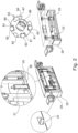
- FIG 2 shows the squeegee device 20 of the additive manufacturing system 100.
- the squeegee device 20 comprises a squeegee turret 60 with a cylindrical base body 67, the peripheral surface of which has at least one receptacle 61 into which a coater element 62 is inserted.
- the coater element 62 is designed to apply or remove the powder material 41 onto or from the building board 31 of the building container 30 .
- the squeegee turret 60 preferably has a plurality of receptacles 61 into which further coater elements 62 are inserted.
- the coating element 62 can be a rubber lip or a blade made of metal and/or ceramic.
- a cleaning element 63 which is designed to remove powder residues after the additive manufacturing of the workpiece, is positioned in one of the plurality of receptacles 61 of the squeegee device 60.
- the cleaning element 63 can be, for example, a silicone-impregnated brush and/or a carbon brush.
- the cleaning element 63 can clean an interface 12 between a floor 11 of the build chamber 10 and the powder container 40, the powder overflow container 35 and/or the build container 30.
- the squeegee turret 60 can rotate and switch over to the cleaning element 63 so that this faces the bottom 11 of the build chamber 10 .
- the cleaning element 63 can thus remove the powder residue and/or the welding spatter from the bottom 11 of the construction chamber 10 and/or the interface 12 between the bottom 11 and the containers 30, 40, 35. In this way it can be ensured that no powder residue can be carried over during the removal of the container.
- an illumination element 64 is positioned in one of the multiple receptacles 61 of the squeegee device 60, which is designed to illuminate the powder layer for recording the image data.
- the lighting element 64 includes at least one Lamps, such as LED, halogen, laser, neon and/or xenon lamp, preferably NIR (Near Infrared) - LED.
- the coater element 62, the cleaning element 63 and/or the lighting element 64 extend at least partially in the longitudinal direction of the cylindrical body 67 of the doctor turret 60.
- the squeegee device 20 also includes a support body 24 to which the squeegee turret 60 is detachably attached by means of a changing mechanism element 66 .
- the changing mechanism element 66 can ensure that the squeegee turret 60 can be removed from the squeegee device 20 easily and quickly.
- the changing mechanism element 66 can have a positive, non-positive, (electro)magnetic and/or clamp connection.
- the squeegee device 20 further comprises at least one distance sensor 21 for detecting a distance between the building board 31 and the coater element 62.
- the distance sensor 21 is arranged on a bottom side 26 of the squeegee device 20 in such a way that it faces the bottom 11 of the build chamber 10.
- the squeegee device 20 preferably includes a plurality of distance sensors 21 in order to enable precise measurement of the distance between the building board 31 and the coater element 62 .
- the distance sensor 21 can also be designed to measure the distance between the coater element 62 and a base plate 43 of the powder container 40 in order to determine the amount of powder material 41 currently present in the powder container 40 .
- the distance sensor 21 can be, for example, an inductive sensor, an ultrasonic sensor or a radar sensor, which enables contactless distance measurement.
- the squeegee device 20 also includes a contact sensor 25 for detecting contact between the building board 31 and the coater element 62.
- the contact sensor 25 is arranged on the bottom side 26 of the squeegee device 20 in such a way that it faces the building board 31 of the building container 30.
- the construction container 30 is coupled to a lifting device 32 which is designed to raise and/or lower the construction panel 31 within the construction container 30 .
- the base plate 43 of the powder container 40 can also be connected to a separate lifting device (not shown) in order to convey the fresh powder material 41 to the bottom 11 of the build chamber.
- the building board 31 can be lifted to the floor 11 of the building chamber 10 by means of the lifting device 32 .
- the contact sensor 25 can detect the contact with the building board 31 at several points.
- the squeegee device 20 can have two or more contact sensors 25 which can be arranged at a distance from one another on the bottom side 26 of the squeegee device 20 . In this way, a position of the building board 31, in particular the height and inclination relative to a horizontal plane, can be precisely detected and corrected according to the measurement results.
- the squeegee device 20 further comprises a fastening element 22 for the detachable fastening of a container cover 33, 42 of the construction container 30 and/or the powder container 40 and a height adjustment element 23 for height mobility of the container cover 33, 42 held.
- a fastening element 22 for the detachable fastening of a container cover 33, 42 of the construction container 30 and/or the powder container 40
- a height adjustment element 23 for height mobility of the container cover 33, 42 held.
- the doctor device 20 moves over a container cover 33, 42 of these containers 30, 40.
- the carrier body 24 of the doctor device 20 can be moved by means of the fastening element 22, which is designed like a T-shaped groove, positively grip the container lid 33, 42 via a connecting element 34 located thereon, which is designed like a T-shaped projection.
- the squeegee device 20 preferably comprises at least two fastening elements 22 and the container lid 33, 42 comprises at least two connecting elements 34, 43 in order to be able to lift the lid 33, 42 of the respective container 30, 40 evenly in the vertical direction.
- the height adjustment element 23 can lift the container lid 33, 42, which has been removed from either the powder container 40 or the construction container 30, in the vertical direction in order to ensure contactless transport of the lid 33, 42 with the construction field. So that the container lid 33, 42 cannot become detached from the doctor device 20 during transport, its movement is restricted by a cam 65 arranged in the doctor turret 60.
- the cam 65 can be arranged in an opposite direction relative to the direction of insertion of the cover 33, 42 onto the squeegee device 20. In this way, the container lid 33, 42 cannot fall off when recording the fastening element 22 of the squeegee device 20 slides out, but this is held in place by the cam 65.
- the construction container lid 33 and powder container lid 42 removed from the squeegee device 20 are transported to a storage location (not shown) which is inside the construction chamber 10 but outside the construction field.
- figure 6 shows powder application monitoring during additive manufacturing.
- the powder material 41 When the powder material 41 is applied, line-like structures can arise in the direction of travel of the squeegee device 20 .
- a visibility of such powder application defect can increase most when illuminated by side lighting to create a shadow.
- the powder application error and/or the coating error can be detected indirectly via a characteristic shadow using the optical element 51, preferably the off-axis camera.
- the control unit (not shown) can use the optical device 50 to detect an application quality of the powder material 41 and determine a fault in the coater element 62 currently being used if the application quality of the powder material 41 deviates from the predetermined requirement.
- the squeegee turret 60 can rotate according to the severity of the damage to the current coater element 62 and switch to a next coater element 62 that is in particular error-free.
- figure 7 shows a flowchart of an additive manufacturing process.
- step S0 the build container 30 and the powder container 40 are inserted into the build chamber 10 of the manufacturing system 100 and the build chamber 10 is then rendered inert in order to minimize the oxygen content in the build chamber 10.
- step S010 the cover 33 of the construction container 30 is detachably connected to the fastening element 22 of the squeegee device 20.
- the lid 33 is raised by means of the height adjustment element 23 and transported to the lid storage location by a horizontal movement of the squeegee device 20 .
- step S020 a position of the building board 31 is aligned.
- the building board 31 is raised to the floor 11 of the building chamber 10 by means of the lifting device 32 S021.
- the contact sensor 25 can detect the contact with the building board 31 at several points S022. In this way, a position of the building board 31, in particular height and inclination recorded precisely relative to a horizontal plane and corrected according to the measurement results S023.
- the building board 31 is then lowered slightly more than 3 mm below the calculated building board position (level 0) upon contact S024.
- the building board 31 can thus be located minimally below level 0.
- Level 0 can be, for example, the position of a floor 11 of the build chamber 10, to which a powder container 40, a build container 30 and/or a powder overflow container can be coupled. In this way it can be ensured that the squeegee device 20 does not come into contact with or collide with the building board 31 during operation, since the coater element can be approx. 0.05 mm above level 0.
- the optical element 51 creates a reference image of the building board S025, which is still untouched by the powder material 41.
- step S1 the powder material 41 is applied to the building board 31 by means of the coating element 62 of the squeegee device 20. After the powder layer has been applied, the building board 31 is raised by an amount of 10-100 ⁇ m S2. The squeegee device 20 then removes part of the raised layer of powder.
- step S3 image data of the powder layer on the building board 31 are recorded by means of the optical device 50, preferably the off-axis camera 51.
- step S31 an image-processing algorithm uses the reference image to check whether the building board 31 is still completely covered with powder or whether areas of the building board that are already untouched by the powder are shining through.
- steps S1 to S3 can be repeated with the removal of a 10-100 ⁇ m thick layer of powder. These steps can be repeated until the optical element 51, i.e. Off-axis camera and the associated algorithm minimum residues of powder material 41 on the building board 31 detects.
- the position of the building board 31 can be set as the starting position for additive manufacturing when only a few areas of the building board 31 are still covered with the powder material 41 .
- the control unit of the production system 100 stores S5 the exact horizontal position of the building board 31 in connection with the coater element 62 that is used Steps are repeated to determine an optimal position of the building board 31 for each coater element 62.
Landscapes
- Engineering & Computer Science (AREA)
- Chemical & Material Sciences (AREA)
- Materials Engineering (AREA)
- Manufacturing & Machinery (AREA)
- Physics & Mathematics (AREA)
- Optics & Photonics (AREA)
- Mechanical Engineering (AREA)
- Plasma & Fusion (AREA)
- Automation & Control Theory (AREA)
- Analytical Chemistry (AREA)
Abstract
Die vorliegende Offenbarung betrifft ein Fertigungssystem zur additiven Fertigung eines Werkstücks und ein additives Fertigungsverfahren. Das Fertigungssystem zur additiven Fertigung eines Werkstücks umfasst eine Bauplatte, eine Hubvorrichtung für die Bauplatte, eine Rakelvorrichtung, eine optische Vorrichtung und eine Steuereinheit. Die Rakelvorrichtung umfasst mindestens ein Beschichterelement zum Aufbringen oder Abtragen eines Pulvermaterials auf die Bauplatte. Die optische Vorrichtung umfasst ein optisches Element zur Aufnahme von Bilddaten von der Bauplatte und/oder von der Pulverschicht. Die Hubvorrichtung ist zum Anheben und/oder Absenken der Bauplatte gestaltet. Die Steuereinheit ist gestaltet, um die Hubvorrichtung auf Grundlage der Bilddaten zu steuern.The present disclosure relates to a manufacturing system for additively manufacturing a workpiece and an additive manufacturing method. The manufacturing system for the additive manufacturing of a workpiece comprises a building board, a lifting device for the building board, a squeegee device, an optical device and a control unit. The squeegee device comprises at least one coating element for applying or removing a powder material onto the building board. The optical device comprises an optical element for recording image data from the building board and/or from the powder layer. The lifting device is designed to raise and/or lower the building board. The control unit is designed to control the lifting device based on the image data.
Description
Die vorliegende Offenbarung betrifft ein Fertigungssystem zur additiven Fertigung eines Werkstücks und ein additives Fertigungsverfahren.The present disclosure relates to a manufacturing system for additively manufacturing a workpiece and an additive manufacturing method.
Additive Fertigung, insbesondere selektives Laserschmelzen (Selective Laser Melting (SLM) oder Laser Powder Bed Fusion (LPBF)) ist ein generatives Fertigungsverfahren, das zur Gruppe der Strahlschmelzverfahren gehört. Beim selektiven Laserschmelzen wird der zu verarbeitende Werkstoff in Pulverform in einer dünnen Schicht auf einer Grundplatte aufgebracht. Der pulverförmige Werkstoff wird mittels Laserstrahlung lokal vollständig umgeschmolzen und bildet nach der Erstarrung eine feste Materialschicht. Anschließend wird die Grundplatte um den Betrag einer Schichtdicke abgesenkt und erneut Pulver aufgetragen. Dieser Zyklus wird so lange wiederholt, bis alle Schichten umgeschmolzen sind. Das fertige Bauteil wird vom überschüssigen Pulver gereinigt und nach Bedarf bearbeitet oder sofort verwendet.Additive manufacturing, in particular selective laser melting (SLM or Laser Powder Bed Fusion (LPBF)) is an additive manufacturing process that belongs to the group of beam melting processes. With selective laser melting, the material to be processed is applied in powder form in a thin layer to a base plate. The powdered material is completely remelted locally using laser radiation and forms a solid layer of material after solidification. The base plate is then lowered by the amount of one layer thickness and powder is applied again. This cycle is repeated until all layers have been remelted. The finished component is cleaned of excess powder and processed as required or used immediately.
Herkömmliche Maschinen für die additive Fertigung sind häufig einfach ausgeführt, daher mangelt es im Vergleich zum Präzisions-Werkzeugmaschinenbau an Robustheit und Genauigkeit. Außerdem erfordert solche Maschine eine zeitaufwendige Einrichtung und Vorbereitung.Conventional machines for additive manufacturing are often of simple design, so they lack robustness and accuracy compared to precision machine tools. In addition, such a machine requires time-consuming set-up and preparation.
Das Fertigungssystem zur additiven Fertigung eines Werkstücks kann daher noch weiter verbessert werden.The manufacturing system for the additive manufacturing of a workpiece can therefore be further improved.
Es ist daher eine Aufgabe der vorliegenden Offenbarung, ein verbessertes Fertigungssystem bereitzustellen, das die Produktivität additiver Fertigung erhöht.It is therefore an object of the present disclosure to provide an improved manufacturing system that increases the productivity of additive manufacturing.
Diese Aufgabe wird durch ein Fertigungssystem zur additiven Fertigung eines Werkstücks und ein additives Fertigungsverfahren nach den unabhängigen Ansprüchen gelöst. Vorteilhafte Ausführungsformen und Weiterbildungen sind den Unteransprüchen und der nachfolgenden Beschreibung zu entnehmen.This object is achieved by a manufacturing system for the additive manufacturing of a workpiece and an additive manufacturing method according to the independent claims. Advantageous embodiments and developments can be found in the dependent claims and the following description.
Die vorliegende Offenbarung umfasst ein Fertigungssystem zur additiven Fertigung eines Werkstücks, umfassend eine Bauplatte, eine Hubvorrichtung für die Bauplatte, eine Rakelvorrichtung, eine optische Vorrichtung, und eine Steuereinheit. Die Rakelvorrichtung umfasst mindestens ein Beschichterelement zum Aufbringen oder Abtragen eines Pulvermaterials auf die oder von der Bauplatte. Die optische Vorrichtung umfasst ein optisches Element zur Aufnahme von Bilddaten von der Bauplatte und/oder von der Pulverschicht. Die Hubvorrichtung ist zum Anheben und/oder Absenken der Bauplatte gestaltet. Die Steuereinheit ist gestaltet, um die Hubvorrichtung auf Grundlage der Bilddaten zu steuern.The present disclosure includes a manufacturing system for additively manufacturing a workpiece, comprising a build plate, a build plate lifter, a squeegee device, an optical device, and a controller. The squeegee device comprises at least one coating element for applying or removing a powder material onto or from the building board. The optical device comprises an optical element for recording image data from the building board and/or from the powder layer. The lifting device is designed to raise and/or lower the building board. The control unit is designed to control the lifting device based on the image data.
Der Vorteil des erfindungsbemäßen Fertigungssystems liegt darin, dass ein einwandfreier Ablauf der additiven Fertigung gewährleistet werden kann. Somit kann die Produktivität der additiven Fertigung erhöht werden. Insbesondere kann eine Echtzeitsteuerung des Fertigungssystems durch eine parallele Überwachung der additiven Fertigung realisiert werden.The advantage of the manufacturing system according to the invention is that additive manufacturing can be guaranteed to run smoothly. Thus, the productivity of additive manufacturing can be increased. In particular, a real-time control of the manufacturing system can be implemented by parallel monitoring of the additive manufacturing.
Das additive Fertigungssystem kann zur Herstellung des Werkstücks durch ein selektives Schmelzen (Selective Laser Melting, SLM) oder Laser Powder Bed Fusion (LPBF) eines Pulvermaterials gestaltet sein.The additive manufacturing system may be configured to produce the workpiece through selective laser melting (SLM) or laser powder bed fusion (LPBF) of a powder material.
Die Rakelvorrichtung kann sich in einer Baukammer des Fertigungssystems befinden. Die Rakelvorrichtung kann zum Auftragen eines frisch aufbereiteten Pulvermaterials auf die Bauplatte und/oder Abtragen eines Restpulvermaterials von der Bauplatte nach einem Schmelzvorgang eingerichtet sein. Durch eine Bewegung der Rakelvorrichtung kann das Beschichterelement in horizontaler Richtung relativ zu der Bauplatte bewegen. Vorzugsweise kann das Beschichterelement einer Oberfläche der Bauplatte, auf die das Pulvermaterial bereitgestellt wird, zugewandt angeordnet sein.The squeegee device can be located in a build chamber of the manufacturing system. The squeegee device can be set up to apply a freshly prepared powder material to the building board and/or to remove residual powder material from the building board after a melting process. By moving the squeegee device, the coater element can move in the horizontal direction relative to the building board. The coating element can preferably be arranged facing a surface of the building board on which the powder material is provided.
Dabei kann das Beschichterelement dazu dienen, das Pulvermaterial beispielsweise aus einem Pulverbehälter einzunehmen und dies auf die Bauplatte schichtweise aufzutragen. Zusätzlich kann das Beschichterelement nach jedem Schmelzvorgang das überschüssige Pulvermaterial und/oder Schweißspritzer, der während der additiven Fertigung entstanden ist, in einen Überlaufbehälter transportieren.In this case, the coating element can serve to take the powder material, for example from a powder container, and to apply this to the building board in layers. In addition, after each melting process, the coater element can transport the excess powder material and/or weld spatter that has arisen during additive manufacturing into an overflow container.
Das Beschichterelement kann beispielsweise eine Gummilippe, eine Klinge aus Metall und/oder Keramik, eine silikon-getränkte Bürste und/oder eine Carbonbürste sein. Das Beschichterelement kann dazu eingerichtet sein, um das Pulvermaterial auf die Bauplatte auf einer vorbestimmten Höhe gleichmäßig aufzutragen und den Pulverrest und/oder Schweißspritzer von der Bauplatte rückstandslos abzutragen.The coating element can be, for example, a rubber lip, a metal and/or ceramic blade, a silicon-impregnated brush and/or a carbon brush. The Coating element can be set up to apply the powder material evenly to the building board at a predetermined height and to remove the powder residue and/or welding spatter from the building board without leaving any residue.
Die Bauplatte kann sich beispielsweise in einem Baubehälter befinden. Die Bauplatte kann dazu dienen, das schichtweise aufgetragene frische Pulvermaterial aufzunehmen und das selektive Schmelzen des Pulvermaterials dort zu ermöglichen. Nach mehrmaligem Wiederholen des Auftragens des Pulvermaterials und selektiven Schmelzens kann schließlich das Werkstück erzeugt werden.The building board can be located in a building container, for example. The building board can serve to receive the fresh powder material applied in layers and to enable the selective melting of the powder material there. Finally, after repeating the application of the powder material and selective melting several times, the workpiece can be produced.
Die Bauplatte kann mit der Hubvorrichtung gekoppelt sein, um eine Bewegung der Bauplatte, insbesondere in vertikaler Richtung, innerhalb des Baubehälters zu ermöglichen. Vorzugsweise kann die Bauplatte nach jedem Schmelzvorgang oder jeder Belichtung des Laserstrahls mittels der Hubvorrichtung schrittweise nach unten herabgesetzt werden, um den nachfolgenden Schmelzvorgang des erneut aufgetragenen Pulvermaterials zu ermöglichen.The building board can be coupled to the lifting device in order to enable movement of the building board, in particular in the vertical direction, within the construction container. Preferably, after each fusing operation or each exposure of the laser beam, the building plate can be incrementally lowered downwards by means of the lifting device in order to allow the subsequent fusing operation of the newly applied powder material.
Das optische Element kann beispielsweise eine Off-axis Überwachungseinrichtung, wie z.B. eine Off-axis Kamera umfassen. Die Off-axis Überwachungseinrichtung kann zur Überwachung einer Wärmeverteilung einer additiv gefertigten Bauteilschicht des Werkstücks gestaltet sein. Mit Hilfe der Off-axis- Überwachungseinrichtung kann auch die Möglichkeit zur Erfassung von Pulverauftragsfehlern bestehen, die während eines Beschichtungsvorgangs auftreten können. Beim Pulverauftrag kann in Fahrtrichtung der Rakelvorrichtung linienartige Strukturen entstehen. Eine Sichtbarkeit solcher Pulverauftragsfehler kann sich am stärksten erhöhen, wenn sie durch eine seitliche Beleuchtung zur Erzeugung eines Schattens angestrahlt werden. Der Pulverauftragsfehler und/oder der Beschichtungsfehler kann indirekt über einen charakteristischen Schatten mit Hilfe der Off-axis- Überwachungseinrichtung erfasst werden.The optical element can, for example, comprise an off-axis monitoring device such as an off-axis camera. The off-axis monitoring device can be designed to monitor a heat distribution of an additively manufactured component layer of the workpiece. The off-axis monitoring device can also be used to detect powder application errors that can occur during a coating process. When applying powder, line-like structures can arise in the direction of travel of the squeegee device. Visibility of such powder application defects can increase most when illuminated by side lighting to create a shadow. The powder application error and/or the coating error can be detected indirectly via a characteristic shadow using the off-axis monitoring device.
Die Steuereinheit kann die von der optischen Vorrichtung generierten Bilddaten empfangen und während der Belichtung einer Pulverschicht auftretende und erfasste Emissionsdaten innerhalb eines Bildes integrieren. Das Resultat dieser Erfassung kann einer Heat-Map der aktuell aufgebauten Schicht entsprechen. Aus dieser Heat-Map kann eine Möglichkeit bestehen, thermische Unregelmäßigkeiten während der additiven Fertigung zu erfassen und bei ausreichend schneller Verarbeitung dieser Informationen bereits gegensteuernde Maßnahmen während einer darauffolgenden Schicht zu ergreifen. Dies kann beispielsweise eine dynamische Anpassung von Belichtungsreihenfolgen zu scannender Bereiche innerhalb einer Schicht, Laserleistungen oder einer Scangeschwindigkeit innerhalb bestimmter Scanbereiche sein. Die Steuereinheit kann zusätzlich auf Grundlage der erfassten Daten und/oder der Heat-Map die Bewegung der Hubvorrichtung kontrollieren, um die Höhe der Bauplatte anzupassen. Auf diese Weise kann die Auftragsqualität des Pulvermaterials, somit die Produktivität additiver Fertigung erhöht werden.The control unit can receive the image data generated by the optical device and integrate emission data occurring and recorded during the exposure of a powder layer within an image. The result of this detection can correspond to a heat map of the currently built up layer. This heat map can be used to detect thermal irregularities during additive manufacturing and, if this information is processed sufficiently quickly, to take countermeasures during a subsequent shift. This can be, for example, a dynamic adjustment of exposure sequences to be scanned areas within a layer, laser power or a scan speed within certain be scan areas. The control unit can additionally control the movement of the lifting device on the basis of the recorded data and/or the heat map in order to adjust the height of the building board. In this way, the application quality of the powder material, and thus the productivity of additive manufacturing, can be increased.
In einer Ausführungsform umfasst die Rakelvorrichtung einen Rakelrevolver mit einem zylindrischen Grundkörper, dessen Umfangsfläche mindestens eine Aufnahme aufweist, in die das Beschichterelement eingefügt ist.In one embodiment, the squeegee device comprises a squeegee turret with a cylindrical base body, the peripheral surface of which has at least one receptacle into which the coater element is inserted.
Der Begriff Revolver kann so verstanden werden, dass es sich um einen Drehkörper handelt, der sich um seine Längsachse dreht. Der Drehkörper kann somit zylindrisch geformt sein. Der zylindrische Drehkörper oder Grundkörper kann an seiner Umfangsfläche mindestens eine Aufnahme umfassen. Die Aufnahme kann beispielsweise als eine Nut geformt sein, die sich zumindest teilweise in Längsrichtung des zylindrischen Grundkörpers erstreckt. In die Aufnahme oder Nut kann das Beschichterelement kraftschlüssig oder formschlüssig verbunden sein. Als Alternative kann die Aufnahme als ein Vorsprung ausgebildet sein, der von der Umfangsfläche des zylindrischen Grundkörpers nach außen vorsteht. An diesem Vorsprung kann das Beschichterelement befestigt sein.The term turret can be understood to mean a rotating body that rotates about its longitudinal axis. The rotating body can thus be cylindrical in shape. The cylindrical rotary body or base body can have at least one receptacle on its peripheral surface. The receptacle can be shaped, for example, as a groove that extends at least partially in the longitudinal direction of the cylindrical base body. The coating element can be connected in a non-positive or positive manner in the receptacle or groove. Alternatively, the seat may be formed as a projection projecting outwardly from the peripheral surface of the cylindrical body. The coater element can be fastened to this projection.
Der Rakelrevolver kann sich auf der Bauplatte im Wesentlichen senkrecht zur Längsachse seines zylindrischen Drehkörpers bewegen. Der Rakelrevolver kann dabei so eingerichtet sein, dass sich der zylindrische Grundkörper solange nicht dreht, bis die Steuereinheit eine Abnormalität der aufgetragenen Pulverschicht erfasst. Mit andren Worten kann ein Beschichterelement solange das Pulvermaterial auf die Bauplatte auftragen und/oder von der Bauplatte abtragen bis die Auftragsqualität des Pulvermaterials eine vorbestimmte Anforderung erfüllt.The squeegee turret can move on the building board essentially perpendicularly to the longitudinal axis of its cylindrical rotary body. The squeegee turret can be set up in such a way that the cylindrical base body does not rotate until the control unit detects an abnormality in the powder layer applied. In other words, a coating element can apply the powder material to the building board and/or remove it from the building board until the application quality of the powder material meets a predetermined requirement.
In einer Ausführungsform weist der Rakelrevolver mindestens eine weitere Aufnahme auf, in die ein weiteres Beschichterelement einfügbar ist. Der Rakelrevolver kann mindestens eine zweite Aufnahme oder mehrere Aufnahmen aufweisen, die an der Umfangsfläche des Rakelrevolvers entlang des Umfangsrichtung voneinander beabstandet angeordnet sind.In one embodiment, the squeegee turret has at least one additional receptacle into which an additional coater element can be inserted. The squeegee turret can have at least one second receptacle or a plurality of receptacles, which are arranged at a distance from one another along the circumferential direction on the peripheral surface of the squeegee turret.
Die Steuereinheit kann beispielsweise mittels der optischen Vorrichtung die Auftragsqualität des Pulvermaterials auswerten und einen Fehler an dem aktuell verwendeten Beschichterelement feststellen, wenn die Auftragsqualität des Pulvermaterials von der vorbestimmten Anforderung abweicht. Im Falle des Fehlers kann sich der Rakelrevolver nach Schwere der Beschädigungen des aktuellen Beschichterelements drehen und auf ein nächstes, insbesondere fehlerfreies Beschichterelement umschalten.The control unit can, for example, use the optical device to evaluate the application quality of the powder material and determine a fault in the coater element currently being used if the application quality of the powder material deviates from the predetermined requirement. In the event of the error, the squeegee turret can Turn the severity of the damage to the current coater element and switch to a next coater element, in particular a coater element that is free of defects.
Auf diese Weise kann ein Zustand des aktuell verwendeten Beschichterelements in Echtzeit überwacht werden und der Fehler oder die Beschädigung des Beschichterelements sofort behoben werden. Somit kann die additive Fertigung ohne Reparaturpause kontinuierlich durchgeführt werden.In this way, a condition of the coater element currently in use can be monitored in real time and the error or damage to the coater element can be rectified immediately. This means that additive manufacturing can be carried out continuously without a break for repairs.
In einer Ausführungsform weist der Rakelrevolver mindestens eine weitere Aufnahme auf, in die ein Reinigungselement zum Abtragen von Pulverresten einfügbar ist. Das Reinigungselement kann beispielsweise eine herkömmliche Bürste, silikon-getränkte Bürste und/oder eine Carbonbürste sein. Das Reinigungselement kann dazu gestaltet sein, nach einem Abschluss der additiven Fertigung einen Boden der Baukammer, der eine Schnittstelle zwischen der Baukammer und dem Pulvervorratsbehälter, dem Pulverüberlaufbehälter und/oder dem Baubehälter umfassen kann, zu reinigen. Das Reinigungselement kann sich in der Aufnahme zumindest teilweise in Längsrichtung des zylindrischen Grundkörpers des Rakelrevolvers erstrecken.In one embodiment, the squeegee turret has at least one further receptacle into which a cleaning element for removing powder residues can be inserted. The cleaning element can be, for example, a conventional brush, a brush impregnated with silicone and/or a carbon brush. The cleaning element can be configured to clean a floor of the build chamber, which can comprise an interface between the build chamber and the powder reservoir, the powder overflow container and/or the build container, after the additive manufacturing has been completed. In the receptacle, the cleaning element can extend at least partially in the longitudinal direction of the cylindrical base body of the squeegee turret.
Nach dem Abschluss der additiven Fertigung kann sich der Rakelrevolver drehen und auf das Reinigungselement umschalten, sodass dieses dem Boden der Baukammer zugewandt ist. Das Reinigungselement kann somit den Pulverrest und/oder den Schweißspritzer vom Boden der Baukammer und/oder der Schnittstelle zwischen der Baukammer und den Behältern abtragen. Auf diese Weise kann es sichergestellt werden, dass kein Pulverrest während der Entnahme der Behälter verschleppt werden kann.After additive manufacturing is complete, the squeegee turret can rotate and switch to the cleaning element so that it faces the bottom of the build chamber. The cleaning element can thus remove the powder residue and/or the welding spatter from the bottom of the build chamber and/or the interface between the build chamber and the containers. In this way it can be ensured that no powder residue can be carried over during the removal of the container.
In einer Ausführungsform weist der Rakelrevolver mindestens eine weitere Aufnahme auf, in die ein Beleuchtungselement zur Beleuchtung der Pulverschicht für die Aufnahme der Bilddaten einfügbar ist. Das Beleuchtungselement kann mindestens ein Leuchtmittel, wie z.B. LED, Halogen, Laser, Neon, Xenon Lampe, etc. umfassen. Vorzugsweise kann das Beleuchtungsmittel NIR (Near Infrared) - LED umfassen.In one embodiment, the squeegee turret has at least one further receptacle into which an illumination element for illuminating the powder layer for capturing the image data can be inserted. The lighting element can include at least one light source, such as an LED, halogen, laser, neon, xenon lamp, etc. The lighting means can preferably include NIR (Near Infrared) LEDs.
Das Beleuchtungselement kann zur Beleuchtung eines Baufeldes dienen, der aktuell von der Rakelvorrichtung überfahren wird. Vorzugsweise kann das Beleuchtungselement das gesamte Baufeld vollständig beleuchten. Das Beleuchtungselement kann sich in der Aufnahme zumindest teilweise in Längsrichtung des Rakelrevolvers erstrecken. Das Beleuchtungsmittel kann dabei so positioniert, dass ein fehlerhafter Pulverauftrag einen Schattenwurf auf der Pulverschicht verursacht, der von dem oberhalb des Baufelds angebrachten optischen Element erfasst wird. Auf diese Weise kann die optische Vorrichtung eine zuverlässige Off-axis Überwachung der Bauplatte und/oder der frisch aufgetragenen Pulverschicht ermöglichen. Der Emissionsbereich der LED kann beispielsweise bei 850 nm liegen.The lighting element can be used to illuminate a construction area that is currently being traversed by the squeegee device. The lighting element can preferably completely illuminate the entire construction field. The lighting element can extend at least partially in the longitudinal direction of the squeegee turret in the receptacle. The lighting means can be positioned so that a faulty application of powder casts a shadow on the powder layer, which is detected by the optical element mounted above the build area. In this way, the optical device can enable reliable off-axis monitoring of the building board and/or the freshly applied powder layer. The emission range of the LED can be 850 nm, for example.
Zusätzlich und/oder alternativ kann die Rakelvorrichtung mindestens ein Beleuchtungselement umfassen, das am Trägerkörper der Rakelvorrichtung vorzugsweise an einer unteren Seite der Rakelvorrichtung in Fahrtrichtung und/oder entgegengesetzter Fahrtrichtung der Rakelvorrichtung angeordnet ist, um das gesamte Baufeld lückenlos zu beleuchten. In einer Ausführungsform ist das optische Element eine Off-axis-Kamera mit einer Filtervorrichtung zur Erfassung von Bilddaten nur mit Wellenlängen zwischen 820 und 870 nm, bevorzugt 830 bis 860 nm. Das optische Element kann in der Baukammer mindestens eine oder zwei hochauflösende Multifunktionskameras mit hoher spektraler Bandbreite umfassen, die während der additiven Fertigung unter Verwendung der Filtervorrichtung, i.e. optischer Bandpassfilter thermische Prozessemissionen erfassen können.Additionally and/or alternatively, the squeegee device can include at least one lighting element, which is arranged on the carrier body of the squeegee device, preferably on a lower side of the squeegee device in the direction of travel and/or in the opposite direction of travel of the squeegee device, in order to illuminate the entire construction area without gaps. In one embodiment, the optical element is an off-axis camera with a filter device for capturing image data only with wavelengths between 820 and 870 nm, preferably 830 to 860 nm. The optical element can have at least one or two high-resolution multifunction cameras in the build chamber spectral bandwidth generated during additive manufacturing using the filter device, i.e. optical bandpass filter can capture thermal process emissions.
Eine Grundvoraussetzung für eine hochstehende Werkstückqualität kann ein fehlerfreier Pulverauftrag während der additiven Fertigung sein. Typische Fehlerbilder können ein lokal unzureichender Pulverauftrag oder Riefen im Pulverbett sein, welches beispielsweise durch lokale Defekte der Rakelvorrichtung entstanden sein kann. Um etwaigen Pulverauftragsfehlern vorzubeugen, kann die frisch aufgetragene Pulverschicht optisch inspiziert werden.A basic requirement for high-quality workpieces can be error-free powder application during additive manufacturing. Typical fault patterns can be a locally insufficient powder application or grooves in the powder bed, which can be caused by local defects in the squeegee device, for example. In order to prevent any powder application errors, the freshly applied powder layer can be visually inspected.
Die Off-axis Kamera kann in der Baukammer angeordnet sein und aufgrund des verwendeten Bandpassfilters für die Off-axis Thermographie ausschließlich Signale im Wellenlängenbereich zwischen 820 und 870 nm, bevorzugt 830 bis 860 nm aufzeichnen. Zur Beleuchtung der frisch aufgetragenen Pulverschicht kann das im Rakelrevolver integrierte Beleuchtungsmittel, e.g. NIR-LED verwendet. Das Beleuchtungsmittel kann dabei so positioniert, dass ein fehlerhafter Pulverauftrag einen Schattenwurf auf der Pulverschicht verursacht, der von der oberhalb des Baufelds angebrachten optischen Vorrichtung erfasst wird.The off-axis camera can be arranged in the build chamber and, because of the bandpass filter used for the off-axis thermography, can only record signals in the wavelength range between 820 and 870 nm, preferably 830 to 860 nm. To illuminate the freshly applied powder layer, the lighting device integrated in the squeegee turret, e.g. NIR LED used. The lighting means can be positioned in such a way that an incorrect powder application causes a shadow to be cast on the powder layer, which is detected by the optical device mounted above the construction area.
Da die Rakelvorrichtung nur einen Teil des Baufelds und/oder der Pulverschicht beleuchten kann, arbeitet die Off-axis-Kamera mit einer Langzeitbelichtung. Die Belichtungszeit der Off-axis-Kamera kann dabei der Überfahrzeit der Rakelvorrichtung auf der Bauplatte angepasst werden. Die Baukammer kann daher so eingerichtet sein, dass keine störenden Lichtsignale von außen in die Baukammer eintreten können. Die Off-axis-Kamera kann ausschließlich das reflektierte Licht von der Pulverbettoberfläche erfassen. Da der frische Pulverauftrag wie auch die Beleuchtung durch die Bewegung der Rakelvorrichtung bei konstanter Geschwindigkeit passiert, entsteht während der Langzeitaufnahme durch die Off-axis-Kamera eine gleichmäßig beleuchtete Aufnahme.Since the squeegee device can only illuminate part of the construction area and/or the powder layer, the off-axis camera works with long-term exposure. The exposure time of the off-axis camera can be adapted to the time the squeegee device travels over the building board become. The build chamber can therefore be set up in such a way that no interfering light signals can enter the build chamber from outside. The off-axis camera can only capture the reflected light from the powder bed surface. Since the fresh powder application and the lighting happen at a constant speed due to the movement of the squeegee device, a uniformly illuminated image is created during the long-term recording by the off-axis camera.
In einer Ausführungsform kann die Off-axis Kamera zur Laserkalibration und/oder Baukammerkalibration gestaltet sein. Durch erhöhte Temperatur innerhalb der Baukammer während des Schmelzvorgangs können thermische Dehnungen der Baukammer, der Bauplatte und/oder der Galvomotoren im Scanner (e.g. Gaindrift und Offsetdrift) nicht vermieden werden.In one embodiment, the off-axis camera can be designed for laser calibration and/or build chamber calibration. Due to the increased temperature within the build chamber during the melting process, thermal expansion of the build chamber, the build plate and/or the galvo motors in the scanner (e.g. gain drift and offset drift) cannot be avoided.
Für die Kamerakalibration kann eine Kalibrierplatte erforderlich sein, auf der ein bestimmtes Kreuzmuster hochpräzise und extrem genau aufgetragen ist (Genauigkeit < 1 µm). Diese Platte kann vor dem Beginn der additiven Fertigung so in die Baukammer gelegt werden, dass das Muster exakt in der zu erwartenden Prozessebene liegt. Die Rakelvorrichtung fährt mit dem eingeschalteten Beleuchtungsmittel über die Kalibrierplatte, so dass die Off-axis-Kamera ein hochauflösendes Bild von der Platte erstellen kann.A calibration plate may be required for camera calibration, on which a specific cross pattern is applied with high precision and with extreme accuracy (accuracy < 1 µm). Before starting additive manufacturing, this plate can be placed in the build chamber in such a way that the pattern lies exactly in the expected process level. The squeegee device moves over the calibration plate with the lighting device switched on, so that the off-axis camera can create a high-resolution image of the plate.
Da die Kamera leicht schräg und nicht absolut vertikal oberhalb des Baufelds angeordnet sein kann, kann das Kamerabild vom Baufeld entzerrt werden (von trapezförmig in rechteckig). Ein in der Steuereinheit hinterlegtes Softwareprogramm kann das (Kreuz-)Muster von der Kalibrierplattenaufnahme erfassen und dieses entzerren. Nach Abschluss der Bildentzerrung können nun alle Aufnahmen mit der Off-axis-Kamera verzerrungsfrei erstellt werden. Die Kamera kann somit als kalibriert gelten.Since the camera can be arranged at a slight angle and not absolutely vertically above the construction area, the camera image can be rectified from the construction area (from trapezoidal to rectangular). A software program stored in the control unit can capture the (cross) pattern from the calibration plate recording and rectify it. Once the image rectification has been completed, all recordings can now be created with the off-axis camera without distortion. The camera can therefore be considered calibrated.
Bei einer ausgeprägten Scanfeldverzerrung können Maßhaltigkeitsverluste auftreten, sodass Scanfeldentzerrungen erforderlich sind. Eine präzise Kamerakalibration der Off-Axis Kamera kann eine Grundvoraussetzung für eine erfolgreiche Umsetzung einer Scanfeldausrichtung sowie Scanfeldentzerrung sein.With a pronounced scan field distortion, dimensional accuracy losses can occur, so that scan field equalization is necessary. A precise camera calibration of the off-axis camera can be a basic requirement for a successful implementation of a scan field alignment and scan field equalization.
Dazu kann der Scanner ein Prüfmuster, das beispielsweise aus 11 x 11 Kreuzen besteht, deren Hauptachsen diagonal zum Referenzkoordinatensystem verlaufen, auf die blanke Bauplatte oder auf eine eloxierte Aluminiumplatte lasern. Die Off-axis-Kamera kann dabei das Scanmuster aufzeichnen. Die Steuereinheit kann anhand der Off-axis-Aufnahme, den genauen Kreuzungspunkt der beiden Hauptachsen der gelaserten Kreuze berechnen. Mittels der kalibrierten Kamera kann nun über die Steuereinheit überprüft werden, ob IST-Positionen der Kreuzungspunkte von den SOLL-Positionen abweichen. Eine mögliche Abweichung von den SOLL-Positionen kann an die Steuereinheit, wie z.B. Scannersoftware übergeben werden, die eine neue Korrekturdatei aus diesen Daten berechnet und an den Scanner zurückgibt. Dieses Prozedere kann mit jedem Scanner erfolgen.To do this, the scanner can laser a test pattern, which consists of 11 x 11 crosses, for example, whose main axes run diagonally to the reference coordinate system, onto the bare building board or onto an anodised aluminum plate. The off-axis camera can record the scan pattern. The control unit can use the off-axis recording to determine the exact Calculate the crossing point of the two main axes of the lasered crosses. Using the calibrated camera, the control unit can now check whether the ACTUAL positions of the crossing points deviate from the TARGET positions. A possible deviation from the TARGET positions can be transferred to the control unit, such as scanner software, which calculates a new correction file from this data and returns it to the scanner. This procedure can be done with any scanner.
Bei der Scanfeldausrichtung kann das Baufeld als Ganzes driften. Bei einer Single-Strahlanlage ist dieser Drift kaum wahrnehmbar. Bei einer Mehrstrahlanlage können sich jedoch die Drifts zweier Scanner aufaddieren, so dass der Gesamtdrift - insbesondere beim gemeinsamen Erzeugen eines Werkstücks - zu Mikroporositäten führen kann, die sich negativ auf die resultierende Werkstücksqualität auswirken. Aufgrund der nicht zu eliminierenden thermischen Einflüsse auf Positionsgenauigkeit der Laser auf dem Baufeld kann eine permanente Scanfeldausrichtung nahezu unerlässlich sein.When aligning the scan field, the construction field can drift as a whole. With a single jet system, this drift is hardly noticeable. With a multi-beam system, however, the drifts of two scanners can add up, so that the total drift - especially when a workpiece is produced together - can lead to microporosities that have a negative effect on the resulting workpiece quality. Due to the thermal influences on the positional accuracy of the lasers on the construction field that cannot be eliminated, permanent alignment of the scanning field can be almost indispensable.
Um zwei oder mehrere Scanfelder aufeinander auszurichten, kann es zweier Stützpunkte -die Kreuzungspunkte zweier sich kreuzender Vektoren zum Einsatz kommen. Ein Scanner kann zwei Kreuze (oder Kreuzungspunkte) auf das Baufeld lasern und prüfen, ob die Kreuzungspunkte von der erwarteten Koordinate abweichen. Liegt eine Abweichung vor, kann das Scanfeld wieder in die vorbestimmte Position gedreht und/oder verschoben werden. Dieses Prozedere kann für jeden Scanner erfolgen. Die Scanfeldausrichtung kann auch während der additiven Fertigung durchgeführt werden. Dafür kann das Softwareprogramm eine zu scannende Fläche der aktuellen Schicht analysieren und dort wo möglich, nach Abschluss eines Schmelzvorgangs zwei Kreuze auf einen Bereich der bereits bestrahlten Fläche setzen.In order to align two or more scan fields with one another, two support points—the crossing points of two crossing vectors—can be used. A scanner can laser two crosses (or crossing points) onto the construction field and check whether the crossing points deviate from the expected coordinates. If there is a deviation, the scan field can be rotated and/or shifted back into the predetermined position. This procedure can be done for any scanner. Scan field alignment can also be performed during additive manufacturing. To do this, the software program can analyze an area of the current layer to be scanned and, where possible, place two crosses on an area of the area that has already been irradiated after a melting process has been completed.
In einer Ausführungsform umfasst die Rakelvorrichtung einen Trägerkörper und der Trägerkörper und/oder der Rakelrevolver umfasst ein Wechselmechanismuselement zur lösbaren Befestigung des Rakelrevolvers an dem Trägerkörper. Das Wechselmechanismuselement kann dafür sorgen, dass der Rakelrevolver einfach und schnell von dem Trägerkörper der Rakelvorrichtung entfernt werden kann. Das Wechselmechanismuselement kann über eine formschlüssige, kraftschlüssige, (elektro-) magnetische und/oder Klemm-Verbindung verfügen. Auf diese Weise kann der Rakelrevolver ohne großen Aufwand einfach und schnell ausgetauscht werden.In one embodiment, the squeegee device comprises a carrier body and the carrier body and/or the squeegee turret comprises a changing mechanism element for the detachable attachment of the squeegee turret to the carrier body. The changing mechanism element can ensure that the squeegee turret can be easily and quickly removed from the carrier body of the squeegee device. The changing mechanism element can have a positive, non-positive, (electro)magnetic and/or clamp connection. In this way, the squeegee turret can be exchanged easily and quickly without great effort.
In einer Ausführungsform umfasst der Trägerkörper und/oder der Rakelrevolver ein Befestigungselement zur lösbaren Befestigung eines Behälterdeckels von einem Baubehälter und/oder einem Pulverbehälter.In one embodiment, the carrier body and/or the squeegee turret comprises a fastening element for the detachable fastening of a container cover of a construction container and/or a powder container.
Zur Aufrechterhaltung einer inertisierten Atmosphäre innerhalb des Bau- und Pulverbehälters sollen die Behälter außerhalb des additiven Fertigungssystems ausschließlich mit aufgesetzten Behälterdeckel gehandhabt werden. Innerhalb der Baukammer können die Behälterdeckel erst abgenommen werden, wenn der Inertisierungszustand der Baukammer vorliegt. Sobald die Schutzgasatmosphäre vorliegt und der Restsauerstoffgehalt unterhalb einer Zielschwelle liegt, können die Behälterdeckel des Bau- und Pulverbehälters mittels der Rakelvorrichtung entnommen werden.To maintain an inert atmosphere inside the build and powder container, the containers should only be handled outside of the additive manufacturing system with the container lid on. Inside the construction chamber, the container lids can only be removed when the construction chamber has been rendered inert. As soon as the protective gas atmosphere is present and the residual oxygen content is below a target threshold, the container lids of the construction and powder container can be removed using the squeegee device.
Dazu kann die Rakelvorrichtung über den Deckel des Baubehälters oder Pulverbehälters fahren. Gleichzeitig können der Trägerkörper und/oder der Rakelrevolver mittels des Befestigungselements, das beispielsweise wie eine T-förmige Nut ausgebildet ist, den Behälterdeckel über ein darauf befindliches Verbindungselement, das beispielsweise wie ein T-förmiger Vorsprung ausgebildet ist, formschlüssig greifen. Das Befestigungselement und das Verbindungselement können jedoch paarweise eine unterschiedliche Form aufweisen, sodass diese formschlüssig lösbar miteinander in Eingriff stehen können. Auf diese Weise können die Behälterdeckel des Baubehälters und/oder Pulverbehälters von dem entsprechenden Behälter einwandfrei entnommen werden.For this purpose, the squeegee device can move over the lid of the construction container or powder container. At the same time, the carrier body and/or the squeegee turret can positively grip the container lid by means of the fastening element, which is designed, for example, like a T-shaped groove, via a connecting element located thereon, which is designed, for example, like a T-shaped projection. However, the fastening element and the connecting element can have a different shape in pairs, so that they can engage with one another in a form-fitting, releasable manner. In this way, the container lid of the construction container and/or powder container can be removed from the corresponding container without any problems.
In einer Ausführungsform umfasst der Trägerkörper und/oder der Rakelrevolver ein Höhenverstellungselement zur Höhenbeweglichkeit des gehaltenen Behälterdeckels. Das Höhenverstellungselement kann den Behälterdeckel, der entweder von dem Pulverbehälter oder dem Baubehälter abgenommen wurde, anheben, um einen kontaktlosen Transport des Deckels mit dem Baufeld sicherzustellen.In one embodiment, the carrier body and/or the squeegee turret comprises a height adjustment element for the height mobility of the container lid held. The height adjustment element can lift the container lid, which has been removed from either the powder container or the construction container, in order to ensure contactless transport of the lid with the construction area.
Damit sich der Behälterdeckel während des Transports zu einem Lagerort nicht von dem Trägerkörper und/oder Rakelrevolver lösen kann, wird er über einen im Rakelrevolver angeordneten Nocken festgehalten. Der Nocken kann in einer entgegengesetzten Richtung relativ zu der Einführrichtung des Deckels angeordnet sein. Auf diese Weise kann der Behälterdeckel bei der Aufnahme beispielsweise über die Rakelvorrichtung nicht aus der T-Nut herausgleitet, sondern wird seine Bewegung durch den Nocken beschränkt. Der Lagerort kann sich innerhalb der Baukammer, jedoch außerhalb des Baufeldes befinden.So that the container lid cannot become detached from the carrier body and/or doctor turret during transport to a storage location, it is held in place by a cam arranged in the doctor turret. The cam may be arranged in an opposite direction relative to the direction of insertion of the lid. In this way, the container lid cannot slide out of the T-groove during pick-up, for example via the squeegee device, but its movement is restricted by the cam. The storage location can be inside the build chamber, but outside the build area.
In einer Ausführungsform umfasst das Fertigungssystem zur additiven Fertigung weiterhin einen Abstandssensor zum Erfassen eines Abstands zwischen der Bauplatte und dem Beschichterelement. Der Abstandssensor kann vorzugsweise an einer Bodenseite der Rakelvorrichtung angeordnet sein, die der Bauplatte zugewandt ist. Das Fertigungssystem und/oder die Rakelvorrichtung kann mehrere Abstandssensoren aufweisen, um eine präzise Messung des Abstands zwischen der Bauplatte und dem Beschichterelement zu ermöglichen. Der Abstandssensor kann ferner zur Abstandsmessung zwischen dem Beschichterelement und einer Grundplatte des Pulverbehälters gestaltet sein, um die Menge des im Pulverbehälter vorhandenen Pulvermaterials präzise zu ermitteln.In one embodiment, the manufacturing system for additive manufacturing also includes a distance sensor for detecting a distance between the building board and the coater element. The distance sensor can preferably be arranged on a bottom side of the squeegee device that faces the building board. The production system and/or the squeegee device can have a number of distance sensors in order to enable precise measurement of the distance between the building board and the coater element. The distance sensor can also be designed to measure the distance between the coater element and a base plate of the powder container in order to precisely determine the amount of powder material present in the powder container.
Der Abstandssensor kann beispielsweise ein induktiver Sensor, ein Ultraschallsensor oder ein Radarsensor sein, der eine berührungslose Abstandsmessung ermöglicht.The distance sensor can be, for example, an inductive sensor, an ultrasonic sensor or a radar sensor, which enables contactless distance measurement.
In einer Ausführungsform umfasst das Fertigungssystem zur additiven Fertigung weiterhin einen Kontaktsensor zum Erfassen eines Kontakts zwischen der Bauplatte und dem Beschichterelement. Der Kontaktsensor kann vorzugsweise an der Bodenseite der Rakelvorrichtung angeordnet sein, die der Bauplatte zugewandt ist. Der Kontaktsensor kann ein taktiler Kontaktsensor sein, der direkt mit der Bauplatte in Berührung kommen kann.In one embodiment, the manufacturing system for additive manufacturing also includes a contact sensor for detecting a contact between the building board and the coater element. The contact sensor can preferably be arranged on the bottom side of the squeegee device that faces the building board. The contact sensor can be a tactile contact sensor that can come in direct contact with the building board.
Vor dem Beginn der additiven Fertigung kann die Bauplatte mittels der Hubvorrichtung an den Boden der Baukammer angehoben werden. Die Rakelvorrichtung kann über die Bauplatte fahren und der Kontaktsensor kann dabei an mehreren Stellen den Kontakt mit der Bauplatte erfassen. Um dies zu erleichtern, kann das Fertigungssystem oder die Rakelvorrichtung zwei oder mehrere Kontaktsensoren aufweisen, die an der Bodenseite der Rakelvorrichtung voneinander beabstandet angeordnet sein können. Auf diese Weise kann eine Position der Bauplatte, insbesondere Höhe und Neigung relative zu einer horizontalen Ebene präzise erfasst werden und entsprechend der Messergebnisse korrigiert werden.Before starting additive manufacturing, the building board can be lifted to the bottom of the building chamber using the lifting device. The squeegee device can move over the building board and the contact sensor can detect contact with the building board at several points. In order to facilitate this, the manufacturing system or the squeegee device can have two or more contact sensors, which can be arranged at a distance from one another on the bottom side of the squeegee device. In this way, a position of the building board, in particular the height and inclination relative to a horizontal plane, can be precisely detected and corrected according to the measurement results.
In einer Ausführungsform umfasst die optische Vorrichtung weiterhin einen On-axis-Sensor, der in einem Strahlengang zur Bestrahlung der Pulverschicht angeordnet ist, um Prozessemissionen aus einem Schmelzbadbereich beim Bestrahlen der Pulverschicht zu erfassen. Der on-axis Sensor kann einen Quotientenpyrometer, Photodioden und/oder eine Hochgeschwindigkeitskamera umfassen, die zur Ermittlung der Temperatur des Pulverbades gestaltet ist. Auf der Bauplatte innerhalb des Baubehälters kann sich das Pulverbad befinden, welches durch das selektive Schmelzen erzeugte Werkstück umgibt.In one embodiment, the optical device further comprises an on-axis sensor, which is arranged in a beam path for irradiating the powder layer, in order to detect process emissions from a melt pool area when irradiating the powder layer. The on-axis sensor may include a ratiometric pyrometer, photodiodes and/or a high speed camera designed to detect the temperature of the powder bath. The powder bath, which surrounds the workpiece produced by the selective melting, can be located on the construction plate within the construction container.
Der Quotientenpyrometer kann dazu ausgelegt sein, die Maximaltemperaturen im Pulverbad zu erfassen. Mit Hilfe der Hochgeschwindigkeitskamera kann eine Pulverbadform und eine Verteilung einer Wärmestrahlungsintensität im Pulverbad erfasst werden, was zu einem verbesserten Gesamtverständnis des Prozesses beitragen kann. Mit den Photodioden kann auch die Wärmestrahlung im Schmelzbad bzw. Pulverbad erfasst werden.The ratio pyrometer can be designed to record the maximum temperatures in the powder bath. A powder bath shape and a distribution of a thermal radiation intensity in the powder bath can be recorded with the aid of the high-speed camera, which can contribute to an improved overall understanding of the process. The photodiodes can also be used to record the thermal radiation in the melt pool or powder bath.
Auf diese Weise kann eine präzise Erfassung der thermischen Prozessemissionen in der Baukammer realisiert werden, wodurch eine Voraussetzung für eine Echtzeitsteuerung der additiven Fertigung erfüllt werden kann.In this way, a precise detection of the thermal process emissions in the build chamber can be realized, which means that a requirement for real-time control of additive manufacturing can be met.
Die vorliegende Offenbarung umfasst weiterhin ein additives Fertigungsverfahren, das die folgenden Schritte umfasst, nicht notwendigerweise in dieser Reihenfolge:
- S1 Aufbringen oder Abtragen eines Pulvermaterials auf eine oder von einer Bauplatte mittels einer Rakelvorrichtung mit mindestens einem Beschichterelement,
- S2 Aufnehmen von Bilddaten von der Bauplatte und/oder von der Pulverschicht mittels einer optische Vorrichtung mit einem optischen, und
- S3 Element Anheben und/oder Absenken der Bauplatte mittels einer Hubvorrichtung, wobei die Hubvorrichtung durch eine Steuereinheit auf Grundlage der Bilddaten gesteuert wird.
- S1 Application or removal of a powder material onto or from a building board by means of a doctor device with at least one coating element,
- S2 recording of image data from the building board and/or from the powder layer by means of an optical device with an optical, and
- S3 element raising and/or lowering the building board by means of a lifting device, the lifting device being controlled by a control unit on the basis of the image data.
Auf diese Weise kann ein einwandfreier Ablauf der additiven Fertigung gewährleitet werden und die Produktivität der additiven Fertigung kann erhöht werden. Insbesondere kann eine Echtzeitsteuerung des Fertigungssystems durch eine parallele Überwachung der additiven Fertigung realisiert werden.In this way, a smooth flow of additive manufacturing can be guaranteed and the productivity of additive manufacturing can be increased. In particular, a real-time control of the manufacturing system can be implemented by parallel monitoring of the additive manufacturing.
In einer Ausführungsform kann das additive Fertigungsverfahren Ausrichten der Bauplatte mittels mindestens eines Kontaktsensors umfassen. Dafür kann die Bauplatte mittels der Hubvorrichtung an den Boden der Baukammer angehoben werden. Der Kontaktsensor kann dabei an mehreren Stellen den Kontakt mit der Bauplatte erfassen. Auf diese Weise kann eine Position der Bauplatte, insbesondre Höhe und Neigung relative zu einer horizontalen Ebene präzise erfasst werden und entsprechend der Messergebnisse korrigiert werden.In one embodiment, the additive manufacturing method can include aligning the building board using at least one contact sensor. To do this, the building board can be lifted to the bottom of the building chamber using the lifting device. The contact sensor can detect contact with the building board at several points. In this way, a position of the building board, in particular its height and inclination relative to a horizontal plane, can be precisely detected and corrected according to the measurement results.
Die Bauplatte kann im Anschluss etwas mehr als 3 mm unterhalb der berechneten Bauplattenposition (Niveau 0) bei Kontakt abgesenkt werden. Somit kann sich die Bauplatte minimal unterhalb des Niveau 0 befinden. Das Niveau 0 kann beispielsweise die Position eines Bodens der Baukammer sein, an dem der Pulverbehälter, der Baubehälter und/oder der Überlaufbehälter gekoppelt werden können. Auf diese Weise kann sichergestellt werden, dass die Rakelvorrichtung beim Betrieb nicht mit der Bauplatte in Kontakt kommt oder kollidiert, da das Beschichterelement ca. 0.05 mm oberhalb von Niveau 0 liegen kann.The building board can then be lowered a little more than 3 mm below the calculated building board position (level 0) on contact. This means that the building board can be slightly below level 0. For example, the level 0 can be the position a floor of the build chamber, to which the powder container, the build container and/or the overflow container can be coupled. In this way it can be ensured that the squeegee device does not come into contact with or collide with the building board during operation, since the coating element can be approx. 0.05 mm above level 0.
In einer Ausführungsform werden die Schritte S1 (Abtragen), S2 (Bilddatenaufnahme) und S3 (Anheben) wiederholt bis die Auswertung ergibt, dass die Bauplatte im Wesentlichen pulverfrei ist. In diesem Fall folgt ein Festlegen der Position des Beschichterelements relativ zu der Bauplatte als Referenzposition für dieses Beschichterelement.In one embodiment, steps S1 (removal), S2 (image data acquisition) and S3 (lifting) are repeated until the evaluation shows that the building board is essentially powder-free. In this case, the position of the coater element relative to the building board is defined as the reference position for this coater element.
Nach der Ausrichtung der Bauplatte kann das optische Element ein Referenzbild von der noch vom Pulvermaterial unberührten Bauplatte erstellen. Im folgenden Schritt kann das Beschichterelement eine Pulverschicht auf die Bauplatte auftragen. Diese Pulverschicht kann, insofern die Position der Bauplatte nach der Ausrichtung der Bauplatte nicht verändert wird, im Mittel eine Stärke von etwa 0.2 + 0.1 mm aufweisen. Nach dem Auftrag der Pulverschicht kann die Bauplatte um einen Betrag von 10 - 100 µm angehoben.After aligning the build plate, the optical element can create a reference image of the build plate still untouched by the powder material. In the next step, the coating element can apply a layer of powder to the building board. Provided that the position of the building board is not changed after the building board has been aligned, this layer of powder can have an average thickness of about 0.2 + 0.1 mm. After applying the powder layer, the building board can be lifted by an amount of 10 - 100 µm.
Die Rakelvorrichtung kann im Anschluss einen Teil der angehobenen Pulverschicht abtragen und zugleich ein Foto von der Pulversituation auf der Bauplatte kann durch das optische Element erstellt werden. Nachdem die Pulverschicht abgetragen wurde, kann ein bildverarbeitender Algorithmus auf Basis des Referenzbildes überprüfen, ob die Bauplatte noch vollständig mit Pulver bedeckt ist oder ob bereits vom Pulver unberührte Bauplattenbereiche durchschimmern.The squeegee device can then remove part of the raised powder layer and at the same time a photo of the powder situation on the building board can be created by the optical element. After the layer of powder has been removed, an image-processing algorithm can use the reference image to check whether the building board is still completely covered with powder or whether areas of the building board that are already untouched by the powder are showing through.
Bestätigt der Algorithmus die noch mit dem Pulvermaterial vollständig bedeckte Bauplatte, kann die Schritte S1 bis S3 mit dem Abtragen einer 10-100 µm starken Pulverschicht wiederholt werden. Diese Schritte können sich so lange wiederholt werden, bis das optische Element, i.e. Off-axis-Kamera und der damit verknüpfte Algorithmus minimale Reste vom Pulvermaterial auf der Bauplatte feststellt. Idealerweise kann die Position der Bauplatte als Startposition der additiven Fertigung eingestellt werden, wenn nur noch wenige Bereiche der Bauplatte mit dem Pulvermaterial bedeckt sind.If the algorithm confirms that the building board is still completely covered with the powder material, steps S1 to S3 can be repeated with the removal of a 10-100 µm thick layer of powder. These steps can be repeated until the optical element, i.e. Off-axis camera and the associated algorithm detects minimal residues of powder material on the build plate. Ideally, the position of the build plate can be set as the starting position for additive manufacturing when only a few areas of the build plate are covered with the powder material.
Das Fertigungssystem, vorzugsweise die Steuereinheit kann dann die genaue horizontale Position der Bauplatte in Verbindung mit dem zum Einsatz kommenden Beschichterelement erfassen und speichern. Für die übrigen Beschichterelemente im Rakelrevolver können die oben beschriebenen Schritte wiederholt werden, um eine optimale Position der Bauplatte für jedes Beschichterelement zu ermitteln. Ist für jedes Beschichterelement innerhalb des Rakelrevolvers die genaue vertikale Position der Bauplatte bekannt, hat es den Vorteil, dass man während der laufenden additiven Fertigung alle zur Verfügung stehenden Beschichterelemente einwandfrei verwenden kann. Bei einem Wechsel des Beschichterelements während des Betriebs kann das Fertigungssystem gegebenenfalls nur geringe Korrekturen der vertikalen Position vornehmen, um die beschichterelementspezifische optimale Position einzunehmen.The production system, preferably the control unit, can then detect and store the exact horizontal position of the building board in connection with the coater element that is used. The steps described above can be repeated for the other coater elements in the squeegee turret in order to achieve an optimal position of the building board for to determine each coater element. If the precise vertical position of the building board is known for each coater element within the squeegee turret, this has the advantage that all available coater elements can be used correctly during the ongoing additive manufacturing process. If the coater element is changed during operation, the production system may only be able to make minor corrections to the vertical position in order to assume the optimum position specific to the coater element.
In einer Ausführungsform ist das Aufnehmen von Bilddaten auf Wellenlängen zwischen 820 und 870 nm, bevorzugt 830 bis 860 nm, beschränkt. Sichtbares Licht und/oder Laserstrahlung wird ausgeblendet. In einer Ausführungsform umfasst das additive Fertigungsverfahren weiterhin ein Beleuchten der Pulverschicht mit Wellenlängen zwischen 820 und 870 nm, bevorzugt 830 bis 860 nm beim Aufnehmen der Bilddaten im Schritt S2. Mit anderen Worten kann das optische Element, i.e. die Off-axis Kamera eine Filtervorrichtung zur Erfassung von Bilddaten nur mit Wellenlängen zwischen 820 und 870 nm, bevorzugt 830 bis 860 nm, aufweisen.In one embodiment, the recording of image data is limited to wavelengths between 820 and 870 nm, preferably 830 to 860 nm. Visible light and/or laser radiation is suppressed. In one embodiment, the additive manufacturing method also includes illuminating the powder layer with wavelengths between 820 and 870 nm, preferably 830 to 860 nm when recording the image data in step S2. In other words, the optical element, i.e. the off-axis camera has a filter device for capturing image data only with wavelengths between 820 and 870 nm, preferably 830 to 860 nm.
Zur Beleuchtung der frisch aufgetragenen Pulverschicht kann das in der Rakelvorrichtung integrierte Beleuchtungsmittel, e.g. NIR-LED-Leiste verwendet. Das Beleuchtungsmittel kann dabei so positioniert, dass ein fehlerhafter Pulverauftrag einen Schattenwurf auf der Pulverschicht provoziert, der von der oberhalb des Baufelds angebrachten optischen Vorrichtung erfasst wird.To illuminate the freshly applied layer of powder, the lighting means integrated in the squeegee device, e.g. NIR LED bar used. The lighting means can be positioned in such a way that an incorrect powder application provokes a shadow to be cast on the powder layer, which is detected by the optical device mounted above the construction area.
Die Baukammer kann daher so eingerichtet sein, dass keine störenden Lichtsignale von außen in die Baukammer eintreten können. Die Off-axis-Kamera kann ausschließlich das reflektierte Licht von der Pulverbettoberfläche erfassen. Da der frische Pulverauftrag wie auch die Beleuchtung durch die Bewegung der Rakelvorrichtung bei konstanter Geschwindigkeit passiert, entsteht während der Langzeitaufnahme durch die Off-axis-Kamera eine gleichmäßig beleuchtete Aufnahme.The build chamber can therefore be set up in such a way that no interfering light signals can enter the build chamber from outside. The off-axis camera can only capture the reflected light from the powder bed surface. Since the fresh powder application and the lighting happen at a constant speed due to the movement of the squeegee device, a uniformly illuminated image is created during the long-term recording by the off-axis camera.
In einer Ausführungsform umfasst das additive Fertigungsverfahren weiterhin ein lösbares Verbinden der Rakelvorrichtung mit einem Behälterdeckel eines Baubehälters und/oder eines Pulverbehälters und ein Transportieren des Behälterdeckels zu einem Lagerort mittels der Rakelvorrichtung.In one embodiment, the additive manufacturing method also includes a detachable connection of the squeegee device to a container lid of a construction container and/or a powder container and transporting the container lid to a storage location by means of the squeegee device.
Zur Aufrechterhaltung einer inertisierten Atmosphäre innerhalb des Bau- und Pulverbehälters sollen die Behälter außerhalb des additiven Fertigungssystems ausschließlich mit aufgesetzten Behälterdeckel gehandhabt werden. Innerhalb der Baukammer können die Behälterdeckel erst abgenommen werden, wenn der Inertisierungszustand der Baukammer vorliegt. Sobald die Schutzgasatmosphäre vorliegt und der Restsauerstoffgehalt unterhalb einer Zielschwelle liegt, können die Behälterdeckel des Bau- und Pulverbehälters mittels der Rakelvorrichtung entnommen werden.To maintain an inert atmosphere inside the build and powder container, the containers should only be handled outside of the additive manufacturing system with the container lid on. Inside the construction chamber, the container lids can only be removed when the construction chamber has been rendered inert. As soon as the protective gas atmosphere is present and the residual oxygen content is below a target threshold, the container lids of the construction and powder container can be removed using the squeegee device.
Dazu kann die Rakelvorrichtung über den Deckel eines Behälters fahren. Gleichzeitig können der Trägerkörper und/oder der Rakelrevolver mittels des Befestigungselements, das beispielsweise wie eine T-förmige Nut ausgebildet ist, den Behälterdeckel über das darauf befindliche Verbindungselement, das beispielsweise wie ein T-förmiger Vorsprung ausgebildet ist, formschlüssig greifen. Auf diese Weise können die Behälterdeckel des Baubehälters und/oder Pulverbehälters von dem entsprechenden Behälter einwandfrei entnommen werden.For this purpose, the squeegee device can move over the lid of a container. At the same time, the carrier body and/or the squeegee turret can positively grip the container lid by means of the fastening element, which is designed, for example, like a T-shaped groove, via the connecting element located thereon, which is designed, for example, like a T-shaped projection. In this way, the container lid of the construction container and/or powder container can be removed from the corresponding container without any problems.
Der von der Rakelvorrichtung aufgenommene Behälterdeckel kann mittels eines Höhenverstellungselements vom Boden der Baukammer angehoben werden, um einen kontaktlosen Transport des Deckels mit dem Baufeld sicherzustellen. Durch eine horizontale Bewegung der Rakelvorrichtung kann der Behälterdeckel zu dem Lagerort transportiert werden. Der Lagerort für den Behälterdeckel kann sich innerhalb der Baukammer, jedoch außerhalb des Baufeldes befinden.The container lid received by the squeegee device can be raised from the bottom of the build chamber by means of a height adjustment element in order to ensure that the lid is transported without contact with the build area. The container lid can be transported to the storage location by a horizontal movement of the squeegee device. The storage location for the container lid can be inside the build chamber, but outside the build area.
Weitere Merkmale, Vorteile und Anwendungsmöglichkeiten der vorliegenden Offenbarung ergeben sich aus der nachfolgenden Beschreibung, den Ausführungsbeispielen und den Figuren. Alle beschriebenen und/oder bildlich dargestellten Merkmale können unabhängig von ihrer Darstellung in einzelnen Ansprüchen, Figuren, Sätzen oder Absätzen miteinander kombiniert werden. In den Figuren stehen gleiche Bezugszeichen für gleiche oder ähnliche Objekte.Further features, advantages and possible applications of the present disclosure result from the following description, the exemplary embodiments and the figures. All features described and/or illustrated can be combined with one another, independently of their representation in individual claims, figures, sentences or paragraphs. In the figures, the same reference symbols stand for the same or similar objects.
- Figur 1figure 1
- zeigt ein Fertigungssystem zur additiven Fertigung eines Werkstücks gemäß einer Ausführungsform.12 shows a manufacturing system for additively manufacturing a workpiece according to an embodiment.
- Figur 2figure 2
- zeigt eine Rakelvorrichtung eines Fertigungssystems zur additiven Fertigung eines Werkstücks gemäß einer Ausführungsform.12 shows a squeegee device of a manufacturing system for the additive manufacturing of a workpiece according to an embodiment.
- Figur 3figure 3
- zeigt ein Fertigungssystem zur additiven Fertigung eines Werkstücks gemäß einer Ausführungsform.12 shows a manufacturing system for additively manufacturing a workpiece according to an embodiment.
- Figur 4figure 4
- zeigt ein Fertigungssystem zur additiven Fertigung eines Werkstücks gemäß einer Ausführungsform.12 shows a manufacturing system for additively manufacturing a workpiece according to an embodiment.
- Figur 5figure 5
- zeigt ein Fertigungssystem zur additiven Fertigung eines Werkstücks gemäß einer Ausführungsform.12 shows a manufacturing system for additively manufacturing a workpiece according to an embodiment.
- Figur 6figure 6
- zeigt ein Fertigungssystem zur additiven Fertigung eines Werkstücks gemäß einer Ausführungsform.12 shows a manufacturing system for additively manufacturing a workpiece according to an embodiment.
- Figur 7figure 7
- zeigt ein Flussdiagramm eines additiven Fertigungsverfahrens.shows a flowchart of an additive manufacturing process.
Die Baukammer 10 weist eine Öffnung auf, die beispielsweise durch ein optisch transparent Material abgedichtet ist. Durch diese Öffnung kann der Laserstrahl bereitgestellt werden, um eine frische Pulverschicht, die auf die Bauplatte 31 aufgetragen ist, zu belichten.The
In der Baukammer 10 befindet sich eine Rakelvorrichtung 20, die das frische Pulvermaterial 41 von dem Pulverbehälter 40 auf die Bauplatte 31 des Baubehälters 30 schichtweise aufträgt und das überschüssige Restpulvermaterial von der Bauplatte 31 in einen Pulverüberlaufbehälter 35 abträgt (siehe auch
Das Fertigungssystem 100 umfasst weiterhin eine optische Vorrichtung 50, die ein Off-axis optisches Element 51 und mindestens einen On-axis Sensor 52 umfasst. Das Off-axis optisches Element 51 kann beispielsweise eine off-axis Kamera umfassen. Das Off-axis optisches Element 51 ist zur Aufnahme von Bilddaten von der Bauplatte und/oder von der Pulverschicht gestaltet. Die Off-axis Kamera 51 weist eine Filtervorrichtung auf, die zur Erfassung von Bilddaten nur mit Wellenlängen zwischen 820 und 870 nm, bevorzugt 830 bis 860 nm gestaltet ist. Der On-axis Sensor 52 kann beispielsweise einen Quotientenpyrometer umfassen. Der On-axis Sensor 52 ist in einem Strahlengang zur Bestrahlung der Pulverschicht angeordnet ist, um Prozessemissionen aus einem Schmelzbadbereich beim Bestrahlen der Pulverschicht zu erfassen.The
In einer der mehreren Aufnahmen 61 der Rakelvorrichtung 60 ist ein Reinigungselement 63 positioniert, das zum Abtragen von Pulverresten nach der additiven Fertigung des Werkstücks gestaltet ist. Das Reinigungselement 63 kann beispielsweise eine silikon-getränkte Bürste und/oder eine Carbonbürste sein.A cleaning
Wie in
Ferner ist in einer der mehreren Aufnahmen 61 der Rakelvorrichtung 60 ein Beleuchtungselement 64 positioniert, das zur Beleuchtung der Pulverschicht für die Aufnahme der Bilddaten gestaltet ist. Das Beleuchtungselement 64 umfasst mindestens ein Leuchtmittel, wie z.B. LED, Halogen, Laser, Neon und/oder Xenon Lampe, vorzugsweise NIR (Near Infrared) - LED.Furthermore, an
Das Beschichterelement 62, das Reinigungselement 63 und/oder das Beleuchtungselement 64 erstrecken sich zumindest teilweise in Längsrichtung des zylindrischen Körpers 67 des Rakelrevolvers 60.The
Die Rakelvorrichtung 20 umfasst weiterhin einen Trägerkörper 24, an dem der Rakelrevolver 60 mittels eines Wechselmechanismuselements 66 lösbar befestigt ist. Das Wechselmechanismuselement 66 kann dafür sorgen, dass der Rakelrevolver 60 einfach und schnell von der Rakelvorrichtung 20 entfernt werden kann. Das Wechselmechanismuselement 66 kann über eine formschlüssige, kraftschlüssige, (elektro-)magnetische und/oder Klemm-Verbindung verfügen.The
Die Rakelvorrichtung 20 umfasst weiterhin mindestens einen Abstandssensor 21 zum Erfassen eines Abstands zwischen der Bauplatte 31und dem Beschichterelement 62. Der Abstandssensor 21 ist auf einer Bodenseite 26 der Rakelvorrichtung 20 so angeordnet, dass er dem Boden 11 der Baukammer 10 zugewandt ist. Die Rakelvorrichtung 20 umfasst vorzugsweise mehrere Abstandsensoren 21, um eine präzise Messung des Abstands zwischen der Bauplatte 31 und dem Beschichterelement 62 zu ermöglichen.The
Der Abstandssensor 21 kann ferner zur Abstandsmessung zwischen dem Beschichterelement 62 und einer Grundplatte 43 des Pulverbehälters 40 gestaltet sein, um die Menge des im Pulverbehälter 40 aktuell vorhandenen Pulvermaterials 41 zu ermitteln. Der Abstandssensor 21 kann beispielsweise ein induktiver Sensor, ein Ultraschallsensor oder ein Radarsensor sein, der eine berührungslose Abstandsmessung ermöglicht.The
Die Rakelvorrichtung 20 umfasst weiterhin einen Kontaktsensor 25 zum Erfassen eines Kontakts zwischen der Bauplatte 31 und dem Beschichterelement 62. Der Kontaktsensor 25 ist an der Bodenseite 26 der Rakelvorrichtung 20 so angeordnet, dass sie der Bauplatte 31 des Baubehälters 30 zugewandt ist.The
Wie in
Vor dem Beginn der additiven Fertigung kann die Bauplatte 31 mittels der Hubvorrichtung 32 an den Boden 11 der Baukammer 10 angehoben werden. Der Kontaktsensor 25 kann dabei an mehreren Stellen den Kontakt mit der Bauplatte 31 erfassen. Um diese Erfassung zu erleichtern, kann die Rakelvorrichtung 20 zwei oder mehrere Kontaktsensoren 25 aufweisen, die an der Bodenseite 26 der Rakelvorrichtung 20 voneinander beabstandet angeordnet sein können. Auf diese Weise kann eine Position der Bauplatte 31, insbesondere Höhe und Neigung relative zu einer horizontalen Ebene präzise erfasst werden und entsprechend der Messergebnisse korrigiert werden.Before the beginning of the additive manufacturing, the
Die Rakelvorrichtung 20 umfasst weiterhin ein Befestigungselement 22 zur lösbaren Befestigung eines Behälterdeckels 33, 42 des Baubehälters 30 und/oder des Pulverbehälters 40 und ein Höhenverstellungselement 23 zur Höhenbeweglichkeit des gehaltenen Behälterdeckels 33, 42. Zur Aufrechterhaltung einer inertisierten Atmosphäre innerhalb des Bau- 30 und Pulverbehälters 40 sollen die Behälter 30, 40 außerhalb des additiven Fertigungssystems 100 ausschließlich mit aufgesetzten Behälterdeckel 33, 42 gehandhabt werden.The
Wie in
Das Höhenverstellungselement 23 kann den Behälterdeckel 33, 42, der entweder von dem Pulverbehälter 40 oder dem Baubehälter 30 abgenommen wurde, in vertikaler Richtung anheben, um einen kontaktlosen Transport des Deckels 33, 42 mit dem Baufeld sicherzustellen. Damit sich der Behälterdeckel 33, 42 während des Transports nicht von der Rakelvorrichtung 20 lösen kann, wird seine Bewegung durch einen im Rakelrevolver 60 angeordneten Nocken 65 beschränkt. Der Nocken 65 kann in einer entgegengesetzten Richtung relativ zu der Einführrichtung des Deckels 33, 42 an die Rakelvorrichtung 20 angeordnet sein. Auf diese Weise kann der Behälterdeckel 33,42 bei der Aufnahme nicht aus dem Befestigungselement 22 der Rakelvorrichtung 20 herausgleitet, sondern wird dieser über den Nocken 65 festgehalten.The
Der von der Rakelvorrichtung 20 entnommenen Baubehälterdeckel 33 und Pulverbehälterdeckel 42 werden zu einem Lagerort (nicht gezeigt) transportiert, der sich innerhalb der Baukammer 10, jedoch außerhalb des Baufeldes befinden.The
Die Steuereinheit (nicht gezeigt) kann mithilfe der optischen Vorrichtung 50 eine Auftragsqualität des Pulvermaterials 41 erfassen und einen Fehler an dem aktuell verwendeten Beschichterelement 62 feststellen, wenn die Auftragsqualität des Pulvermaterials 41 von der vorbestimmten Anforderung abweicht. Im Falle des Fehlers kann sich der Rakelrevolver 60 nach Schwere der Beschädigungen des aktuellen Beschichterelements 62 drehen und auf ein nächstes, insbesondere fehlerfreies Beschichterelement 62 umschalten.The control unit (not shown) can use the
Im Schritt S0 werden der Baubehälter 30 und der Pulverbehälter 40 in die Baukammer 10 des Fertigungssystems 100 eingefügt und die Baukammer 10 wird anschließend inertisiert, um den Sauerstoffgehalt in der Baukammer 10 zu minimieren.In step S0, the
Im Schritt S010 wird der Deckel 33 des Baubehälters 30 lösbar mit dem Befestigungselement 22 der Rakelvorrichtung 20 verbunden. Der Deckel 33 wird mittels des Höhenverstellungselements 23 angehoben und durch eine horizontale Bewegung der Rakelvorrichtung 20 zu dem Deckellagerort transportiert.In step S010, the
Im Schritt S020 wird eine Position der Bauplatte 31 ausgerichtet. Dafür wird die Bauplatte 31 mittels der Hubvorrichtung 32 an den Boden 11 der Baukammer 10 angehoben S021. Der Kontaktsensor 25 kann dabei an mehreren Stellen den Kontakt mit der Bauplatte 31 erfassen S022. Auf diese Weise wird eine Position der Bauplatte 31, insbesondere Höhe und Neigung relative zu einer horizontalen Ebene präzise erfasst und entsprechend der Messergebnisse korrigiert S023.In step S020, a position of the
Die Bauplatte 31 wird im Anschluss etwas mehr als 3 mm unterhalb der berechneten Bauplattenposition (Niveau 0) bei Kontakt abgesenkt S024. Somit kann sich die Bauplatte 31 minimal unterhalb des Niveau 0 befinden. Das Niveau 0 kann beispielsweise die Position eines Bodens 11 der Baukammer 10 sein, an dem ein Pulverbehälter 40, ein Baubehälter 30 und/oder ein Pulverüberlaufbehälter gekoppelt werden können. Auf diese Weise kann sichergestellt werden, dass die Rakelvorrichtung 20 beim Betrieb nicht mit der Bauplatte 31 in Kontakt kommt oder kollidiert, da das Beschichterelement ca. 0.05 mm oberhalb von Niveau 0 liegen kann. Nach der Ausrichtung der Bauplatte 31 erstellt das optische Element 51 ein Referenzbild von der noch vom Pulvermaterial 41 unberührten Bauplatte S025.The
Im folgenden Schritt S1 wird das Pulvermaterial 41 mittels des Beschichterelements 62 der Rakelvorrichtung 20 auf die Bauplatte 31 aufgetragen. Nach dem Auftrag der Pulverschicht wird die Bauplatte 31 um einen Betrag von 10 - 100 µm angehoben S2. Die Rakelvorrichtung 20 trägt im Anschluss einen Teil der angehobenen Pulverschicht ab.In the following step S1, the
Im Schritt S3 werden Bilddaten von der Pulverschicht auf der Bauplatte 31 mittels der optischen Vorrichtung 50, vorzugsweise der Off-axis Kamera 51 aufgenommen. Im Schritt S31 überprüft ein bildverarbeitender Algorithmus auf Basis des Referenzbildes, ob die Bauplatte 31 noch vollständig mit Pulver bedeckt ist oder ob bereits vom Pulver unberührte Bauplattenbereiche durchschimmern.In step S3, image data of the powder layer on the
Bestätigt S4 der Algorithmus die noch mit dem Pulvermaterial 41 vollständig bedeckte Bauplatte 31, kann die Schritte S1 bis S3 mit dem Abtragen einer 10-100 µm starken Pulverschicht wiederholt werden. Diese Schritte können sich so lange wiederholt werden, bis das optische Element 51, i.e. Off-axis-Kamera und der damit verknüpfte Algorithmus minimale Reste vom Pulvermaterial 41 auf der Bauplatte 31 feststellt. Idealerweise kann die Position der Bauplatte 31 als Startposition der additiven Fertigung eingestellt werden, wenn nur noch wenige Bereiche der Bauplatte 31 mit dem Pulvermaterial 41 bedeckt sind.If the algorithm S4 confirms that the
Die Steuereinheit des Fertigungssystems 100 speichert S5 die genaue horizontale Position der Bauplatte 31 in Verbindung mit dem zum Einsatz kommenden Beschichterelement 62. Für die übrigen Beschichterelemente 62 im Rakelrevolver 60 können die oben beschriebenen Schritte wiederholt werden, um eine optimale Position der Bauplatte 31 für jedes Beschichterelement 62 zu ermitteln.The control unit of the
Ergänzend sei darauf hingewiesen, dass "umfassend" und "aufweisend" keine anderen Elemente oder Schritte ausschließt. Ferner sei darauf hingewiesen, dass Merkmale oder Schritte, die mit Verweis auf eines der obigen Ausführungsbeispiele beschrieben worden sind, auch in Kombination mit anderen Merkmalen oder Schritten anderer oben beschriebener Ausführungsbeispiele verwendet werden können. Bezugszeichen in den Ansprüchen sind nicht als Einschränkung anzusehen.In addition, it should be pointed out that "comprising" and "comprising" do not exclude any other elements or steps. Furthermore, it should be pointed out that features or steps that have been described with reference to one of the above exemplary embodiments can also be used in combination with other features or steps of other exemplary embodiments described above. Any reference signs in the claims should not be construed as limiting.
Claims (17)
Priority Applications (2)
| Application Number | Priority Date | Filing Date | Title |
|---|---|---|---|
| EP21197233.6A EP4151342A1 (en) | 2021-09-16 | 2021-09-16 | Manufacturing system for additive production of a workpiece |
| US17/946,133 US20230078772A1 (en) | 2021-09-16 | 2022-09-16 | Manufacturing system for additive manufacturing of a workpiece |
Applications Claiming Priority (1)
| Application Number | Priority Date | Filing Date | Title |
|---|---|---|---|
| EP21197233.6A EP4151342A1 (en) | 2021-09-16 | 2021-09-16 | Manufacturing system for additive production of a workpiece |
Publications (1)
| Publication Number | Publication Date |
|---|---|
| EP4151342A1 true EP4151342A1 (en) | 2023-03-22 |
Family
ID=77801630
Family Applications (1)
| Application Number | Title | Priority Date | Filing Date |
|---|---|---|---|
| EP21197233.6A Pending EP4151342A1 (en) | 2021-09-16 | 2021-09-16 | Manufacturing system for additive production of a workpiece |
Country Status (2)
| Country | Link |
|---|---|
| US (1) | US20230078772A1 (en) |
| EP (1) | EP4151342A1 (en) |
Cited By (2)
| Publication number | Priority date | Publication date | Assignee | Title |
|---|---|---|---|---|
| DE102022129042B3 (en) | 2022-11-03 | 2023-09-21 | additiveStream4D GmbH | Calibration system and calibration method for calibrating a building platform system in an additive manufacturing device |
| WO2024094256A1 (en) | 2022-11-03 | 2024-05-10 | additiveStream4D GmbH | Calibration system and calibration method for calibrating a construction platform system in an additive manufacturing device |
Citations (9)
| Publication number | Priority date | Publication date | Assignee | Title |
|---|---|---|---|---|
| US20070037509A1 (en) * | 2005-05-31 | 2007-02-15 | Bernd Renz | Method for the manufacture of a molding as well as a sensor unit for the application thereof |
| WO2014095200A1 (en) * | 2012-12-17 | 2014-06-26 | Arcam Ab | Additive manufacturing method and apparatus |
| US20150165683A1 (en) * | 2013-12-13 | 2015-06-18 | General Electric Company | Operational performance assessment of additive manufacturing |
| US20160236279A1 (en) * | 2013-09-23 | 2016-08-18 | Renishaw Plc | Additive manufacturing apparatus and method |
| US20180124341A1 (en) * | 2016-10-28 | 2018-05-03 | General Electric Company | Imaging devices for use with additive manufacturing systems and methods of imaging a build layer |
| EP3495077A1 (en) * | 2016-08-02 | 2019-06-12 | Xi'an Bright Laser Technologies Co., Ltd. | Powder spreading quality test method and additive manufacturing device |
| US20190366433A1 (en) * | 2016-09-22 | 2019-12-05 | Siemens Aktiengesellschaft | Producing Workpieces With an Additive Production Method |
| CN111940733A (en) * | 2020-07-20 | 2020-11-17 | 北京科技大学 | Device and method for removing splashed oxide and compensating powder supply in selective laser melting process |
| US20210053279A1 (en) * | 2019-08-23 | 2021-02-25 | Canon Kabushiki Kaisha | Method of manufacturing three-dimensionally shaped object, additive manufacturing apparatus, and powder depositing apparatus |
-
2021
- 2021-09-16 EP EP21197233.6A patent/EP4151342A1/en active Pending
-
2022
- 2022-09-16 US US17/946,133 patent/US20230078772A1/en active Pending
Patent Citations (9)
| Publication number | Priority date | Publication date | Assignee | Title |
|---|---|---|---|---|
| US20070037509A1 (en) * | 2005-05-31 | 2007-02-15 | Bernd Renz | Method for the manufacture of a molding as well as a sensor unit for the application thereof |
| WO2014095200A1 (en) * | 2012-12-17 | 2014-06-26 | Arcam Ab | Additive manufacturing method and apparatus |
| US20160236279A1 (en) * | 2013-09-23 | 2016-08-18 | Renishaw Plc | Additive manufacturing apparatus and method |
| US20150165683A1 (en) * | 2013-12-13 | 2015-06-18 | General Electric Company | Operational performance assessment of additive manufacturing |
| EP3495077A1 (en) * | 2016-08-02 | 2019-06-12 | Xi'an Bright Laser Technologies Co., Ltd. | Powder spreading quality test method and additive manufacturing device |
| US20190366433A1 (en) * | 2016-09-22 | 2019-12-05 | Siemens Aktiengesellschaft | Producing Workpieces With an Additive Production Method |
| US20180124341A1 (en) * | 2016-10-28 | 2018-05-03 | General Electric Company | Imaging devices for use with additive manufacturing systems and methods of imaging a build layer |
| US20210053279A1 (en) * | 2019-08-23 | 2021-02-25 | Canon Kabushiki Kaisha | Method of manufacturing three-dimensionally shaped object, additive manufacturing apparatus, and powder depositing apparatus |
| CN111940733A (en) * | 2020-07-20 | 2020-11-17 | 北京科技大学 | Device and method for removing splashed oxide and compensating powder supply in selective laser melting process |
Cited By (2)
| Publication number | Priority date | Publication date | Assignee | Title |
|---|---|---|---|---|
| DE102022129042B3 (en) | 2022-11-03 | 2023-09-21 | additiveStream4D GmbH | Calibration system and calibration method for calibrating a building platform system in an additive manufacturing device |
| WO2024094256A1 (en) | 2022-11-03 | 2024-05-10 | additiveStream4D GmbH | Calibration system and calibration method for calibrating a construction platform system in an additive manufacturing device |
Also Published As
| Publication number | Publication date |
|---|---|
| US20230078772A1 (en) | 2023-03-16 |
Similar Documents
| Publication | Publication Date | Title |
|---|---|---|
| EP3362262B1 (en) | Method and recoater for a device for the production of a three-dimensional object | |
| EP4151342A1 (en) | Manufacturing system for additive production of a workpiece | |
| DE102014205726B4 (en) | METHOD FOR DETERMINING PROFILE DATA FOR AN EDGE FEATURE IN A MACHINE IMAGE PROCESSING INSPECTION SYSTEM | |
| EP2983898B1 (en) | Method for automatic calibration of a device for generative production of a three-dimensional object | |
| DE3318980C2 (en) | Device for adjustment during projection copying of masks | |
| DE102017203853B4 (en) | Board inspection device | |
| EP3610500B1 (en) | Component reception apparatus with optical sensor | |
| DE4222804A1 (en) | Automatic visual tester for electrical and electronic components - performs video scans of different surfaces with unequal intensities of illumination by annular and halogen lamps | |
| DE112018008046T5 (en) | DEVICE FOR ADDITIVE MANUFACTURING | |
| DE102017212371B4 (en) | Determination of a mark in a data record with three-dimensional surface coordinates of a scene detected by means of at least one laser scanner | |
| DE102019211028B4 (en) | Robot system and calibration method | |
| DE3809221A1 (en) | METHOD FOR DETECTING DEFECTS IN PRESSING PARTS OR OTHER WORKPIECES, AND DEVICE FOR IMPLEMENTING THE METHOD | |
| DE102021000808A1 (en) | Test method and test system for columnar honeycomb structure made of ceramic | |
| DE202009005329U1 (en) | cutter | |
| DE102018217940A1 (en) | Method and processing machine for processing a workpiece | |
| WO2022171621A1 (en) | Method for optimising a machining time of a laser machining process, method for carrying out a laser machining process on a workpiece, and laser machining system designed for carrying out this process | |
| WO2020099402A1 (en) | Improved calibration method for a system for powder bed-based generating of three-dimensional components by means of electromagnetic radiation | |
| DE102013112666A1 (en) | Method for detaching semiconductor chip from foil, involves assigning process step to last frame assigned time/derived time period while showing that no edge region in image of chip is darker than predetermined brightness value | |
| DE202020101810U1 (en) | Device for determining an actual state of support strips of a workpiece support and machine tool with such a device | |
| WO2019002325A1 (en) | Measurement system for a device for generatively producing a three-dimensional object | |
| DE102022204693A1 (en) | PROTECTIVE FILM THICKNESS MEASUREMENT | |
| EP1443542B1 (en) | Method and device for controlling the edge of a disc shaped arcticle | |
| DE102022100717A1 (en) | AUTOMATED BEAM SCAN CALIBRATION, ALIGNMENT AND ADJUSTMENT | |
| DE102008010965B4 (en) | Robot web guide | |
| WO2021185899A1 (en) | Method and device for determining an actual state of support bars of a workpiece support, and machine tool having a device of this type |
Legal Events
| Date | Code | Title | Description |
|---|---|---|---|
| PUAI | Public reference made under article 153(3) epc to a published international application that has entered the european phase |
Free format text: ORIGINAL CODE: 0009012 |
|
| STAA | Information on the status of an ep patent application or granted ep patent |
Free format text: STATUS: REQUEST FOR EXAMINATION WAS MADE |
|
| 17P | Request for examination filed |
Effective date: 20220802 |
|
| AK | Designated contracting states |
Kind code of ref document: A1 Designated state(s): AL AT BE BG CH CY CZ DE DK EE ES FI FR GB GR HR HU IE IS IT LI LT LU LV MC MK MT NL NO PL PT RO RS SE SI SK SM TR |
|
| RAP3 | Party data changed (applicant data changed or rights of an application transferred) |
Owner name: UNITED GRINDING GROUP MANAGEMENT AG |
|
| STAA | Information on the status of an ep patent application or granted ep patent |
Free format text: STATUS: EXAMINATION IS IN PROGRESS |
|
| 17Q | First examination report despatched |
Effective date: 20230502 |
|
| GRAP | Despatch of communication of intention to grant a patent |
Free format text: ORIGINAL CODE: EPIDOSNIGR1 |
|
| STAA | Information on the status of an ep patent application or granted ep patent |
Free format text: STATUS: GRANT OF PATENT IS INTENDED |
|
| INTG | Intention to grant announced |
Effective date: 20240319 |
|
| GRAS | Grant fee paid |
Free format text: ORIGINAL CODE: EPIDOSNIGR3 |