EP4124193A1 - Immersion cooling system - Google Patents
Immersion cooling system Download PDFInfo
- Publication number
- EP4124193A1 EP4124193A1 EP22179510.7A EP22179510A EP4124193A1 EP 4124193 A1 EP4124193 A1 EP 4124193A1 EP 22179510 A EP22179510 A EP 22179510A EP 4124193 A1 EP4124193 A1 EP 4124193A1
- Authority
- EP
- European Patent Office
- Prior art keywords
- condenser
- main body
- tank
- space
- cooling system
- Prior art date
- Legal status (The legal status is an assumption and is not a legal conclusion. Google has not performed a legal analysis and makes no representation as to the accuracy of the status listed.)
- Pending
Links
Images


Classifications
-
- H—ELECTRICITY
- H05—ELECTRIC TECHNIQUES NOT OTHERWISE PROVIDED FOR
- H05K—PRINTED CIRCUITS; CASINGS OR CONSTRUCTIONAL DETAILS OF ELECTRIC APPARATUS; MANUFACTURE OF ASSEMBLAGES OF ELECTRICAL COMPONENTS
- H05K7/00—Constructional details common to different types of electric apparatus
- H05K7/20—Modifications to facilitate cooling, ventilating, or heating
- H05K7/2029—Modifications to facilitate cooling, ventilating, or heating using a liquid coolant with phase change in electronic enclosures
- H05K7/203—Modifications to facilitate cooling, ventilating, or heating using a liquid coolant with phase change in electronic enclosures by immersion
-
- H—ELECTRICITY
- H05—ELECTRIC TECHNIQUES NOT OTHERWISE PROVIDED FOR
- H05K—PRINTED CIRCUITS; CASINGS OR CONSTRUCTIONAL DETAILS OF ELECTRIC APPARATUS; MANUFACTURE OF ASSEMBLAGES OF ELECTRICAL COMPONENTS
- H05K7/00—Constructional details common to different types of electric apparatus
- H05K7/20—Modifications to facilitate cooling, ventilating, or heating
- H05K7/2029—Modifications to facilitate cooling, ventilating, or heating using a liquid coolant with phase change in electronic enclosures
- H05K7/20318—Condensers
-
- H—ELECTRICITY
- H05—ELECTRIC TECHNIQUES NOT OTHERWISE PROVIDED FOR
- H05K—PRINTED CIRCUITS; CASINGS OR CONSTRUCTIONAL DETAILS OF ELECTRIC APPARATUS; MANUFACTURE OF ASSEMBLAGES OF ELECTRICAL COMPONENTS
- H05K7/00—Constructional details common to different types of electric apparatus
- H05K7/20—Modifications to facilitate cooling, ventilating, or heating
- H05K7/2029—Modifications to facilitate cooling, ventilating, or heating using a liquid coolant with phase change in electronic enclosures
- H05K7/20327—Accessories for moving fluid, for connecting fluid conduits, for distributing fluid or for preventing leakage, e.g. pumps, tanks or manifolds
Definitions
- the present disclosure relates to immersion cooling systems.
- immersion cooling system In the application of immersion cooling system, a user will immerse the large electronic equipment into the cooling liquid inside the immersion cooling system, in order to deliver away the heat generated by the electronic equipment during operation.
- a technical aspect of the present disclosure is to provide an immersion cooling system, which can effectively avoid the chance of outflow of the cooling liquid from the tank due to the poor sealing condition of the tank, and thus effectively control the cost of operation of the immersion cooling system.
- an immersion cooling system includes a tank, a first condenser, an enclosure, a second condenser and a connecting pipe.
- the tank has a first space.
- the first space is configured to accommodate a cooling liquid for at least one electronic equipment to immerse therein.
- the first condenser is disposed inside the tank.
- the enclosure is disposed outside the tank.
- the enclosure forms a second space together with the tank.
- the second condenser is disposed in the second space.
- the connecting pipe includes a first end and a second end opposite to the first end. The first end is connected with the second condenser. The second end is communicated with the first space.
- the second condenser and the first condenser are separated from each other.
- the immersion cooling system further includes a first sealing element.
- the first sealing element is sealed between the enclosure and the tank.
- the immersion cooling system further includes a check valve.
- the check valve is disposed on the connecting pipe.
- the tank has an opening.
- the opening is communicated between the first space and the second space.
- the immersion cooling system further includes a cover.
- the cover is pivotally connected with the tank and is configured to open or close the opening.
- the immersion cooling system further includes a second sealing element.
- the second sealing element is sealed between the cover and the tank.
- the second condenser further includes a main body, a fan, an input port and an output port.
- the main body is connected with the connecting pipe.
- the main body is configured to condense a gas into a liquid.
- the main body has at least one first through hole.
- the fan is connected with the main body.
- the fan is configured to absorb the gas into the main body through the first through hole.
- the input port is communicated with the main body.
- the input port is configured to allow a water to flow into the main body.
- the output port is communicated with the main body.
- the output port is configured to allow the water to flow away from the main body.
- the second condenser further includes at least one extension pipe.
- the extension pipe is connected with the main body.
- the extension pipe is communicated with the first through hole.
- the extension pipe has a plurality of second through holes. The second through holes are arranged along an extending direction of the extension pipe.
- a quantity of the first through hole and a quantity of the extension pipe are respectively plural.
- the first condenser includes a main body, an input port and an output port.
- the input port and the output port are respectively communicated with the main body.
- the input port is configured to allow a water to flow into the main body.
- the output port is configured to allow the water to flow away from the main body.
- the main body is configured to condense a gas into a liquid.
- the second condenser is independently operational from the first condenser.
- the first condenser is a water-cooling condenser.
- the second condenser is an air-cooling condenser separated from the water-cooling condenser.
- Fig. 1 is a sectional view of an immersion cooling system 100 according to an embodiment of the present disclosure.
- an immersion cooling system 100 includes a tank 110, a first condenser 120, an enclosure 130, a second condenser 140 and a connecting pipe 150.
- the tank 110 has a first space S1.
- the first space S1 is configured to accommodate a cooling liquid CL for at least one electronic equipment 200 to immerse therein.
- the electronic equipment 200 generates heat.
- the hot electronic equipment 200 evaporates a portion of the cooling liquid CL to form a vapor CV.
- the vapor CV being heated up floats upwards and leaves from the cooling liquid CL.
- the first condenser 120 is disposed inside the tank 110.
- the first condenser 120 is configured to condense the vapor CV in the first space S1, such that the vapor CV reverts to the cooling liquid CL in the liquid form. In this way, through repeated conversions between the gas form and the liquid form of the cooling liquid CL, a fluid circulation is formed in the first space S1 of the tank 110.
- the enclosure 130 is disposed outside the tank 110.
- the enclosure 130 forms a second space S2 together with an outer surface of the tank 110.
- a portion of the cooling liquid CL is heated up to form the vapor CV in the first space S1.
- the vapor CV in the first space S1 may leak and leave from the tank 110.
- the enclosure 130 is disposed outside the tank 110 and forms a second space S2 together with the outer surface of the tank 110, the vapor CV leaked from the first space S1 of the tank 110 will be collected within the second space S2.
- the second condenser 140 is disposed in the second space S2.
- the second condenser 140 is configured to condense the vapor CV leaked to the second space S2, such that the vapor CV reverts to the cooling liquid CL in the liquid form.
- the connecting pipe 150 includes a first end 151 and a second end 152 opposite to the first end 151.
- the first end 151 of the connecting pipe 150 is connected with the second condenser 140.
- the second end 152 of the connecting pipe 150 is communicated with the first space S1. Therefore, the cooling liquid CL reverted to the liquid form by the second condenser 140 can first enter into the first end 151 of the connecting pipe 150 and then flow back to the cooling liquid CL in the first space S1 from the second end 152 of the connecting pipe 150 after flowing through the connecting pipe 150.
- the immersion cooling system 100 is able to effectively avoid the chance of outflow of the cooling liquid CL from the tank 110 due to the poor sealing condition of the tank 110.
- the cost of operation of the immersion cooling system 100 can be effectively controlled.
- the second condenser 140 and the first condenser 120 are separated from each other. This means the second condenser 140 and the first condenser 120 are independently operational from each other. In other words, for example, during the operation of the first condenser 120, the second condenser 140 can be stopped from operating according to the actual situation. Therefore, the immersion cooling system 100 has a good flexibility of operation.
- the first condenser 120 can be a water-cooling condenser.
- the first condenser 120 includes a main body 121, an input port 122 and an output port 123.
- the input port 122 and the output port 123 are respectively communicated with the main body 121.
- the input port 122 is configured to allow a water W to flow into the main body 121.
- the output port 123 is configured to allow the water W to flow away from the main body 121.
- the main body 121 is configured to condense a gas into a liquid.
- the main body 121 condenses the vapor CV in the first space S1 into the cooling liquid CL.
- the immersion cooling system 100 further includes a check valve 170.
- the check valve 170 is disposed on the connecting pipe 150.
- the check valve 170 is configured to restrict the flowing direction of the cooling liquid CL inside the connecting pipe 150.
- the check valve 170 allows the cooling liquid CL to flow from the second condenser 140 to the first space S1, but restricts the cooling liquid CL or the vapor CV evaporated from the cooling liquid CL from flowing to the second condenser 140 from the first space S1 via the connecting pipe 150.
- Fig. 2 is a partially enlarged view of the area A of Fig. 1 .
- the immersion cooling system 100 further includes a first sealing element 160.
- the first sealing element 160 is sealed between the enclosure 130 and the tank 110, in order to increase the degree of sealing between the enclosure 130 and the tank 110.
- the chance of leakage of the vapor CV from the second space S2 formed together by the enclosure 130 and the tank 110 is reduced.
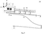
- Fig. 3 is a schematic enlarged view of the second condenser 140 of Fig. 1 .
- Fig. 4 is a partially exploded view of the second condenser 140 of Fig. 3 .
- the second condenser 140 can be a water-cooling condenser.
- the second condenser 140 further includes a main body 141, a fan 142, an input port 143 and an output port 144.
- the main body 141 is connected with the first end 151 of the connecting pipe 150.
- the main body 141 has at least one first through hole H1 (please see Fig. 4 ).
- the main body 141 is configured to condense a gas into a liquid. That means the main body 141 condenses the vapor CV in the second space S2 into the cooling liquid CL, and the cooling liquid CL then flows back to the first space S1 through the connecting pipe 150.
- the fan 142 is connected with the main body 141.
- the fan 142 is configured to absorb the gas into the main body 141 through the first through hole H1. That means the fan 142 absorbs the vapor CV in the second space S2 into the main body 141 through the first through hole H1.
- the input port 143 is communicated with the main body 141.
- the input port 143 is configured to allow a water W to flow into the main body 141.
- the output port 144 is communicated with the main body 141.
- the output port 144 is configured to allow the water W to flow away from the main body 141. Through the flow of the water W within the main body 141, the main body 141 condenses the vapor CV in the second space S2 into the cooling liquid
- the second condenser 140 further includes at least one extension pipe 145.
- the extension pipe 145 is connected with the main body 141.
- the extension pipe 145 is communicated with the first through hole H1.
- the extension pipe 145 has a plurality of second through holes H2.
- the second through holes H2 are arranged along an extending direction of the extension pipe 145.
- a quantity of the first through hole H1 and a quantity of the extension pipe 145 can respectively be plural. However, this does not intend to limit the present disclosure.
- the fan 142 is at least partially exposed outside the main body 141. After the vapor CV in the second space S2 is absorbed into the main body 141 by the fan 142, the gas accompanied with the vapor CV absorbed or the vapor CV not yet condensed by the main body 141 will be discharged out of the main body 141 through the fan 142.
- the second condenser 140 can be a non-water-cooling condenser.
- the second condenser 140 can be an air-cooling condenser or a thermoelectric cooler condenser. Under these conditions, the second condenser 140 does not include the input port 143 and the output port 144 mentioned above.
- Fig. 5 is a sectional view of an immersion cooling system 100 of Fig. 1 , in which the cover 180 is in an opening status.
- the tank 110 has an opening OP.
- the opening OP is communicated between the first space S1 and the second space S2.
- the immersion cooling system 100 further includes a cover 180.
- the cover 180 is pivotally connected with the tank 110, and is configured to rotate relative to the tank 110 in order to open or close the opening OP.
- the cover 180 isolates the first space S1 from the second space S2. This means the first space S1 and the second space S2 are not communicated with each other.
- the immersion cooling system 100 is able to effectively avoid the outflow of the cooling liquid CL, and thus the cost of operation of the immersion cooling system 100 can be effectively controlled.
- Fig. 6 is a partially enlarged view of the area B of Fig. 1 .
- the immersion cooling system 100 further includes a second sealing element 190.
- the second sealing element 190 is sealed between the cover 180 and the tank 110.
- the second sealing element 190 can increase the degree of sealing between the cover 180 and the tank 110.
- the chance of leakage of the vapor CV from the first space S1 is reduced.
Landscapes
- Engineering & Computer Science (AREA)
- Microelectronics & Electronic Packaging (AREA)
- Physics & Mathematics (AREA)
- Thermal Sciences (AREA)
- Cooling Or The Like Of Semiconductors Or Solid State Devices (AREA)
Abstract
Description
- The present disclosure relates to immersion cooling systems.
- During the operation of large electronic equipment, in order to effectively avoid the reduction of operational performance and even damage due to its generation of excessive heat, the way to carry out effective heat dissipation to the large electronic equipment under a reliable condition is undoubtedly an important issue to the industry.
- In the application of immersion cooling system, a user will immerse the large electronic equipment into the cooling liquid inside the immersion cooling system, in order to deliver away the heat generated by the electronic equipment during operation.
- A technical aspect of the present disclosure is to provide an immersion cooling system, which can effectively avoid the chance of outflow of the cooling liquid from the tank due to the poor sealing condition of the tank, and thus effectively control the cost of operation of the immersion cooling system.
- According to an embodiment of the present disclosure, an immersion cooling system includes a tank, a first condenser, an enclosure, a second condenser and a connecting pipe. The tank has a first space. The first space is configured to accommodate a cooling liquid for at least one electronic equipment to immerse therein. The first condenser is disposed inside the tank. The enclosure is disposed outside the tank. The enclosure forms a second space together with the tank. The second condenser is disposed in the second space. The connecting pipe includes a first end and a second end opposite to the first end. The first end is connected with the second condenser. The second end is communicated with the first space.
- In one or more embodiments of the present disclosure, the second condenser and the first condenser are separated from each other.
- In one or more embodiments of the present disclosure, the immersion cooling system further includes a first sealing element. The first sealing element is sealed between the enclosure and the tank.
- In one or more embodiments of the present disclosure, the immersion cooling system further includes a check valve. The check valve is disposed on the connecting pipe.
- In one or more embodiments of the present disclosure, the tank has an opening. The opening is communicated between the first space and the second space. The immersion cooling system further includes a cover. The cover is pivotally connected with the tank and is configured to open or close the opening.
- In one or more embodiments of the present disclosure, the immersion cooling system further includes a second sealing element. The second sealing element is sealed between the cover and the tank.
- In one or more embodiments of the present disclosure, the second condenser further includes a main body, a fan, an input port and an output port. The main body is connected with the connecting pipe. The main body is configured to condense a gas into a liquid. The main body has at least one first through hole. The fan is connected with the main body. The fan is configured to absorb the gas into the main body through the first through hole. The input port is communicated with the main body. The input port is configured to allow a water to flow into the main body. The output port is communicated with the main body. The output port is configured to allow the water to flow away from the main body.
- In one or more embodiments of the present disclosure, the second condenser further includes at least one extension pipe. The extension pipe is connected with the main body. The extension pipe is communicated with the first through hole. The extension pipe has a plurality of second through holes. The second through holes are arranged along an extending direction of the extension pipe.
- In one or more embodiments of the present disclosure, a quantity of the first through hole and a quantity of the extension pipe are respectively plural.
- In one or more embodiments of the present disclosure, the first condenser includes a main body, an input port and an output port. The input port and the output port are respectively communicated with the main body. The input port is configured to allow a water to flow into the main body. The output port is configured to allow the water to flow away from the main body. The main body is configured to condense a gas into a liquid.
- In one or more embodiments of the present disclosure, the second condenser is independently operational from the first condenser.
- In one or more embodiments of the present disclosure, the first condenser is a water-cooling condenser. The second condenser is an air-cooling condenser separated from the water-cooling condenser.
- The above-mentioned embodiments of the present disclosure have at least the following advantages:
- (1) Even if the tank is in a poor sealing condition, the vapor leaked from the tank can be collected within the second space formed by the enclosure and the tank together. Afterwards, the vapor leaked from the tank and collected within the second space can be condensed by the second condenser in the second space to revert to the cooling liquid of the liquid form, which then flows back to the cooling liquid in the first space through the connecting pipe. In this way, the immersion cooling system is able to effectively avoid the chance of outflow of the cooling liquid from the tank due to the poor sealing condition of the tank. Thus, the cost of operation of the immersion cooling system can be effectively controlled.
- (2) Since the second condenser and the first condenser are independently operational from each other, the immersion cooling system has a good flexibility of operation.
- (3) When the cover is opened relative to the opening during the maintenance of the immersion cooling system, since the enclosure is disposed outside the tank and forms the second space together with the tank, the vapor left from the first space through the opening of the tank will be collected in the second space. In this way, the immersion cooling system is able to effectively avoid the outflow of the cooling liquid, and thus the cost of operation of the immersion cooling system can be effectively controlled.
- The disclosure can be more fully understood by reading the following detailed description of the embodiments, with reference made to the accompanying drawings as follows:
-
Fig. 1 is a sectional view of an immersion cooling system according to an embodiment of the present disclosure; -
Fig. 2 is a partially enlarged view of the area A ofFig. 1 ; -
Fig. 3 is a schematic enlarged view of the second condenser ofFig. 1 ; -
Fig. 4 is a partially exploded view of the second condenser ofFig. 3 ; -
Fig. 5 is a sectional view of an immersion cooling system ofFig. 1 , in which the cover is in an opening status; and -
Fig. 6 is a partially enlarged view of the area B ofFig. 1 . - Drawings will be used below to disclose embodiments of the present disclosure. For the sake of clear illustration, many practical details will be explained together in the description below. However, it is appreciated that the practical details should not be used to limit the claimed scope. In other words, in some embodiments of the present disclosure, the practical details are not essential. Moreover, for the sake of drawing simplification, some customary structures and elements in the drawings will be schematically shown in a simplified way. Wherever possible, the same reference numbers are used in the drawings and the description to refer to the same or like parts.
- Unless otherwise defined, all terms (including technical and scientific terms) used herein have the same meanings as commonly understood by one of ordinary skill in the art to which this disclosure belongs. It will be further understood that terms, such as those defined in commonly used dictionaries, should be interpreted as having a meaning that is consistent with their meaning in the context of the relevant art and the present disclosure, and will not be interpreted in an idealized or overly formal sense unless expressly so defined herein.
- Reference is made to
Fig. 1. Fig. 1 is a sectional view of animmersion cooling system 100 according to an embodiment of the present disclosure. In this embodiment, as shown inFig. 1 , animmersion cooling system 100 includes atank 110, a first condenser 120, anenclosure 130, asecond condenser 140 and a connectingpipe 150. Thetank 110 has a first space S1. The first space S1 is configured to accommodate a cooling liquid CL for at least oneelectronic equipment 200 to immerse therein. During the operation of theelectronic equipment 200, theelectronic equipment 200 generates heat. The hotelectronic equipment 200 evaporates a portion of the cooling liquid CL to form a vapor CV. The vapor CV being heated up floats upwards and leaves from the cooling liquid CL. The first condenser 120 is disposed inside thetank 110. The first condenser 120 is configured to condense the vapor CV in the first space S1, such that the vapor CV reverts to the cooling liquid CL in the liquid form. In this way, through repeated conversions between the gas form and the liquid form of the cooling liquid CL, a fluid circulation is formed in the first space S1 of thetank 110. - Furthermore, the
enclosure 130 is disposed outside thetank 110. Theenclosure 130 forms a second space S2 together with an outer surface of thetank 110. As mentioned above, during the operation of theelectronic equipment 200, a portion of the cooling liquid CL is heated up to form the vapor CV in the first space S1. At this point, in case thetank 110 is badly sealed, the vapor CV in the first space S1 may leak and leave from thetank 110. However, since theenclosure 130 is disposed outside thetank 110 and forms a second space S2 together with the outer surface of thetank 110, the vapor CV leaked from the first space S1 of thetank 110 will be collected within the second space S2. Thesecond condenser 140 is disposed in the second space S2. Thesecond condenser 140 is configured to condense the vapor CV leaked to the second space S2, such that the vapor CV reverts to the cooling liquid CL in the liquid form. The connectingpipe 150 includes afirst end 151 and asecond end 152 opposite to thefirst end 151. Thefirst end 151 of the connectingpipe 150 is connected with thesecond condenser 140. Thesecond end 152 of the connectingpipe 150 is communicated with the first space S1. Therefore, the cooling liquid CL reverted to the liquid form by thesecond condenser 140 can first enter into thefirst end 151 of the connectingpipe 150 and then flow back to the cooling liquid CL in the first space S1 from thesecond end 152 of the connectingpipe 150 after flowing through the connectingpipe 150. - In other words, even if the
tank 110 is in a poor sealing condition, the vapor CV leaked from thetank 110 can be collected within the second space S2 formed by theenclosure 130 and the outer surface of thetank 110 together. Afterwards, the vapor CV leaked from thetank 110 and collected within the second space S2 can be condensed by thesecond condenser 140 in the second space S2 to revert to the cooling liquid CL in the liquid form, which then flows back to the cooling liquid CL in the first space S1 through the connectingpipe 150. In this way, theimmersion cooling system 100 is able to effectively avoid the chance of outflow of the cooling liquid CL from thetank 110 due to the poor sealing condition of thetank 110. Thus, the cost of operation of theimmersion cooling system 100 can be effectively controlled. - In this embodiment, the
second condenser 140 and the first condenser 120 are separated from each other. This means thesecond condenser 140 and the first condenser 120 are independently operational from each other. In other words, for example, during the operation of the first condenser 120, thesecond condenser 140 can be stopped from operating according to the actual situation. Therefore, theimmersion cooling system 100 has a good flexibility of operation. - In practical applications, for example, the first condenser 120 can be a water-cooling condenser. To be specific, as shown in
Fig. 1 , the first condenser 120 includes amain body 121, aninput port 122 and anoutput port 123. Theinput port 122 and theoutput port 123 are respectively communicated with themain body 121. Theinput port 122 is configured to allow a water W to flow into themain body 121. Theoutput port 123 is configured to allow the water W to flow away from themain body 121. Through the flow of the water W within themain body 121, themain body 121 is configured to condense a gas into a liquid. To be precise, themain body 121 condenses the vapor CV in the first space S1 into the cooling liquid CL. - In addition, as shown in
Fig. 1 , theimmersion cooling system 100 further includes acheck valve 170. Thecheck valve 170 is disposed on the connectingpipe 150. Thecheck valve 170 is configured to restrict the flowing direction of the cooling liquid CL inside the connectingpipe 150. To be specific, thecheck valve 170 allows the cooling liquid CL to flow from thesecond condenser 140 to the first space S1, but restricts the cooling liquid CL or the vapor CV evaporated from the cooling liquid CL from flowing to thesecond condenser 140 from the first space S1 via the connectingpipe 150. - Reference is made to
Fig. 2. Fig. 2 is a partially enlarged view of the area A ofFig. 1 . In practical applications, as shown inFig. 2 , theimmersion cooling system 100 further includes afirst sealing element 160. Thefirst sealing element 160 is sealed between theenclosure 130 and thetank 110, in order to increase the degree of sealing between theenclosure 130 and thetank 110. Thus, the chance of leakage of the vapor CV from the second space S2 formed together by theenclosure 130 and thetank 110 is reduced. - Reference is made to
Figs. 3-4 .Fig. 3 is a schematic enlarged view of thesecond condenser 140 ofFig. 1 .Fig. 4 is a partially exploded view of thesecond condenser 140 ofFig. 3 . In practical applications, for example, thesecond condenser 140 can be a water-cooling condenser. As shown inFigs. 3-4 , thesecond condenser 140 further includes amain body 141, afan 142, aninput port 143 and anoutput port 144. Themain body 141 is connected with thefirst end 151 of the connectingpipe 150. Themain body 141 has at least one first through hole H1 (please seeFig. 4 ). Themain body 141 is configured to condense a gas into a liquid. That means themain body 141 condenses the vapor CV in the second space S2 into the cooling liquid CL, and the cooling liquid CL then flows back to the first space S1 through the connectingpipe 150. Thefan 142 is connected with themain body 141. Thefan 142 is configured to absorb the gas into themain body 141 through the first through hole H1. That means thefan 142 absorbs the vapor CV in the second space S2 into themain body 141 through the first through hole H1. Theinput port 143 is communicated with themain body 141. Theinput port 143 is configured to allow a water W to flow into themain body 141. Theoutput port 144 is communicated with themain body 141. Theoutput port 144 is configured to allow the water W to flow away from themain body 141. Through the flow of the water W within themain body 141, themain body 141 condenses the vapor CV in the second space S2 into the cooling liquid CL. - Moreover, the
second condenser 140 further includes at least oneextension pipe 145. Theextension pipe 145 is connected with themain body 141. Theextension pipe 145 is communicated with the first through hole H1. Theextension pipe 145 has a plurality of second through holes H2. The second through holes H2 are arranged along an extending direction of theextension pipe 145. When thefan 142 operates, the vapor CV in the second space S2 is absorbed into theextension pipe 145 through the second through holes H2. Subsequently, the vapor CV in theextension pipe 145 is absorbed into themain body 141 through the first through hole H1 and is then condensed into the cooling liquid CL by themain body 141. Through theextension pipe 145 and the second through holes H2 distributed thereon, the vapor CV in the second space S2 can be absorbed into themain body 141 in an easier manner. According to the actual situation, a quantity of the first through hole H1 and a quantity of theextension pipe 145 can respectively be plural. However, this does not intend to limit the present disclosure. - Furthermore, the
fan 142 is at least partially exposed outside themain body 141. After the vapor CV in the second space S2 is absorbed into themain body 141 by thefan 142, the gas accompanied with the vapor CV absorbed or the vapor CV not yet condensed by themain body 141 will be discharged out of themain body 141 through thefan 142. - In other embodiments, the
second condenser 140 can be a non-water-cooling condenser. For example, thesecond condenser 140 can be an air-cooling condenser or a thermoelectric cooler condenser. Under these conditions, thesecond condenser 140 does not include theinput port 143 and theoutput port 144 mentioned above. - Reference is made to
Fig. 5. Fig. 5 is a sectional view of animmersion cooling system 100 ofFig. 1 , in which thecover 180 is in an opening status. In this embodiment, as shown inFig. 5 , thetank 110 has an opening OP. The opening OP is communicated between the first space S1 and the second space S2. Theimmersion cooling system 100 further includes acover 180. Thecover 180 is pivotally connected with thetank 110, and is configured to rotate relative to thetank 110 in order to open or close the opening OP. As shown inFig. 1 , when thecover 180 closes the opening OP, thecover 180 isolates the first space S1 from the second space S2. This means the first space S1 and the second space S2 are not communicated with each other. On the other hands, for example, as shown inFig. 5 , when thecover 180 is opened relative to the opening OP during the maintenance of theimmersion cooling system 100, the first space S1 and the second space S2 are communicated with each other. As mentioned above, since theenclosure 130 is disposed outside thetank 110 and forms the second space S2 together with the outer surface of thetank 110, the vapor CV left from the first space S1 through the opening OP of thetank 110 will be collected in the second space S2. In this way, theimmersion cooling system 100 is able to effectively avoid the outflow of the cooling liquid CL, and thus the cost of operation of theimmersion cooling system 100 can be effectively controlled. - Reference is made to
Fig. 6. Fig. 6 is a partially enlarged view of the area B ofFig. 1 . In practical applications, as shown inFig. 6 , theimmersion cooling system 100 further includes asecond sealing element 190. Thesecond sealing element 190 is sealed between thecover 180 and thetank 110. When thecover 180 closes the opening OP, thesecond sealing element 190 can increase the degree of sealing between thecover 180 and thetank 110. Thus, the chance of leakage of the vapor CV from the first space S1 is reduced. - In conclusion, the aforementioned embodiments of the present disclosure have at least the following advantages:
- (1) Even if the tank is in a poor sealing condition, the vapor leaked from the tank can be collected within the second space formed by the enclosure and the tank together. Afterwards, the vapor leaked from the tank and collected within the second space can be condensed by the second condenser in the second space to revert to the cooling liquid of the liquid form, which then flows back to the cooling liquid in the first space through the connecting pipe. In this way, the immersion cooling system is able to effectively avoid the chance of outflow of the cooling liquid from the tank due to the poor sealing condition of the tank. Thus, the cost of operation of the immersion cooling system can be effectively controlled.
- (2) Since the second condenser and the first condenser are independently operational from each other, the immersion cooling system has a good flexibility of operation.
- (3) When the cover is opened relative to the opening during the maintenance of the immersion cooling system, since the enclosure is disposed outside the tank and forms the second space together with the tank, the vapor left from the first space through the opening of the tank will be collected in the second space. In this way, the immersion cooling system is able to effectively avoid the outflow of the cooling liquid, and thus the cost of operation of the immersion cooling system can be effectively controlled.
Claims (12)
- An immersion cooling system (100), characterized in that, comprising:a tank (110) having a first space (S1) configured to accommodate a cooling liquid (CL) for at least one electronic equipment (200) to immerse therein;a first condenser (120) disposed inside the tank (110);an enclosure (130) disposed outside the tank (110) and forming a second space (S2) together with the tank (110);a second condenser (140) disposed in the second space (S2); anda connecting pipe (150) comprising a first end (151) and a second end (152) opposite to the first end (151), the first end (151) connecting with the second condenser (140), the second end (152) being communicated with the first space (S1).
- The immersion cooling system (100) of claim 1, characterized in that, the second condenser (140) and the first condenser (120) are separated from each other.
- The immersion cooling system (100) of claim 1 or 2, characterized in that, further comprising:
a first sealing element (160) sealed between the enclosure (130) and the tank (110). - The immersion cooling system (100) of any one of claims 1-3, characterized in that, further comprising:
a check valve (170) disposed on the connecting pipe (150). - The immersion cooling system (100) of any one of claims 1-4, characterized in that, the tank (110) has an opening (OP) communicated between the first space (S1) and the second space (S2), the immersion cooling system (100) further comprises:
a cover (180) pivotally connected with the tank (110) and configured to open or close the opening (OP). - The immersion cooling system (100) of claim 5, characterized in that, further comprising:
a second sealing element (190) sealed between the cover (180) and the tank (110). - The immersion cooling system (100) of any one of claims 1-6, characterized in that, the second condenser (140) further comprises:a main body (141) connected with the connecting pipe (150) and configured to condense a gas into a liquid, the main body (141) having at least one first through hole (H1);a fan (142) connected with the main body (141) and configured to absorb the gas into the main body (141) through the first through hole (H1);an input port (143) communicated with the main body (141) and configured to allow a water (W) to flow into the main body (141); andan output port (144) communicated with the main body (141) and configured to allow the water (W) to flow away from the main body (141).
- The immersion cooling system (100) of claim 7, characterized in that, the second condenser (140) further comprises:
at least one extension pipe (145) connected with the main body (141) and communicated with the first through hole (H1), the extension pipe (145) has a plurality of second through holes (H2) arranged along an extending direction of the extension pipe (145). - The immersion cooling system (100) of claim 8, characterized in that, a quantity of the first through hole (H1) and a quantity of the extension pipe (145) are respectively plural.
- The immersion cooling system (100) of any one of claims 1-9, characterized in that, the first condenser (120) comprises a main body (121), an input port (122) and an output port (123), the input port (122) and the output port (123) are respectively communicated with the main body (121), the input port (122) is configured to allow a water (W) to flow into the main body (121), the output port (122) is configured to allow the water (W) to flow away from the main body (121), and the main body (121) is configured to condense a gas into a liquid.
- The immersion cooling system (100) of any one of claims 1-10, characterized in that, the second condenser (140) is independently operational from the first condenser (120).
- The immersion cooling system (100) of any one of claims 1-11, characterized in that, the first condenser (120) is a water-cooling condenser, the second condenser (140) is an air-cooling condenser separated from the water-cooling condenser.
Applications Claiming Priority (2)
| Application Number | Priority Date | Filing Date | Title |
|---|---|---|---|
| US202163223984P | 2021-07-21 | 2021-07-21 | |
| CN202210117207.1A CN115696846A (en) | 2021-07-21 | 2022-02-08 | Immersion cooling system |
Publications (1)
| Publication Number | Publication Date |
|---|---|
| EP4124193A1 true EP4124193A1 (en) | 2023-01-25 |
Family
ID=84688567
Family Applications (1)
| Application Number | Title | Priority Date | Filing Date |
|---|---|---|---|
| EP22179510.7A Pending EP4124193A1 (en) | 2021-07-21 | 2022-06-17 | Immersion cooling system |
Country Status (2)
| Country | Link |
|---|---|
| US (1) | US20230026658A1 (en) |
| EP (1) | EP4124193A1 (en) |
Families Citing this family (2)
| Publication number | Priority date | Publication date | Assignee | Title |
|---|---|---|---|---|
| US11696422B2 (en) * | 2021-08-18 | 2023-07-04 | Baidu Usa Llc | Highly serviceable immersion cooling structural design for servers |
| US11700714B2 (en) * | 2021-08-24 | 2023-07-11 | Baidu Usa Llc | Integrated immersion system for servers |
Citations (5)
| Publication number | Priority date | Publication date | Assignee | Title |
|---|---|---|---|---|
| GB2389174A (en) * | 2002-05-01 | 2003-12-03 | Rolls Royce Plc | An apparatus with a plurality of heat exchanges using an evaporating liquid means for cooling a component |
| GB2549946A (en) * | 2016-05-03 | 2017-11-08 | Bitfury Group Ltd | Immersion cooling |
| US20200236808A1 (en) * | 2014-06-24 | 2020-07-23 | David Lane Smith | System and method for fluid cooling of electronic devices installed in an enclosure |
| US10765033B1 (en) * | 2019-05-23 | 2020-09-01 | Microsoft Technology Licensing, Llc | Immersion cooling enclosures with insulating liners |
| US20210059079A1 (en) * | 2019-08-23 | 2021-02-25 | Microsoft Technology Licensing, Llc | Mitigating vapor loss in a two-phase immersion cooling system |
-
2022
- 2022-05-17 US US17/663,827 patent/US20230026658A1/en active Pending
- 2022-06-17 EP EP22179510.7A patent/EP4124193A1/en active Pending
Patent Citations (5)
| Publication number | Priority date | Publication date | Assignee | Title |
|---|---|---|---|---|
| GB2389174A (en) * | 2002-05-01 | 2003-12-03 | Rolls Royce Plc | An apparatus with a plurality of heat exchanges using an evaporating liquid means for cooling a component |
| US20200236808A1 (en) * | 2014-06-24 | 2020-07-23 | David Lane Smith | System and method for fluid cooling of electronic devices installed in an enclosure |
| GB2549946A (en) * | 2016-05-03 | 2017-11-08 | Bitfury Group Ltd | Immersion cooling |
| US10765033B1 (en) * | 2019-05-23 | 2020-09-01 | Microsoft Technology Licensing, Llc | Immersion cooling enclosures with insulating liners |
| US20210059079A1 (en) * | 2019-08-23 | 2021-02-25 | Microsoft Technology Licensing, Llc | Mitigating vapor loss in a two-phase immersion cooling system |
Also Published As
| Publication number | Publication date |
|---|---|
| US20230026658A1 (en) | 2023-01-26 |
Similar Documents
| Publication | Publication Date | Title |
|---|---|---|
| EP4124193A1 (en) | Immersion cooling system | |
| KR101776718B1 (en) | Heat exchanger for vehicle | |
| KR101405186B1 (en) | Heat exchanger for vehicle | |
| US7753108B2 (en) | Liquid cooling device | |
| US6889515B2 (en) | Spray cooling system | |
| US6377458B1 (en) | Integrated EMI containment and spray cooling module utilizing a magnetically coupled pump | |
| KR101283591B1 (en) | Heat exchanger for vehicle | |
| TWI402032B (en) | Device for cooling an elecronic apparatus | |
| US7122075B2 (en) | Device for reducing the gas and water contamination of transformer oil filling | |
| TWI831127B (en) | Immersion cooling system | |
| US20220087050A1 (en) | Heat dissipation apparatus and processor | |
| US20080137299A1 (en) | System and method that dissipate heat from an electronic device | |
| EP4124191A1 (en) | Immersion cooling system | |
| WO2024000890A1 (en) | Liquid cooling apparatus | |
| JP4849097B2 (en) | Waste heat recovery unit | |
| US11934237B2 (en) | Hybrid motherboard cooling system for air-cooled servers | |
| EP3965542A2 (en) | Heat dissipation system and server system | |
| CN113939138A (en) | Heat sink and communication device | |
| TWM592641U (en) | Steady flow pressure-charging device of condenser | |
| US20190154344A1 (en) | Radiator | |
| KR101161793B1 (en) | Cooling safety valve apparatus | |
| KR102582411B1 (en) | Passive cooling installation | |
| US20230320033A1 (en) | Separate immersion cooling device and separate immersion cooling system having the same | |
| CN219395354U (en) | Electric control assembly, air conditioner outdoor unit and air conditioner | |
| US20220128311A1 (en) | Vapor-phase/liquid-phase fluid heat exchange uni |
Legal Events
| Date | Code | Title | Description |
|---|---|---|---|
| PUAI | Public reference made under article 153(3) epc to a published international application that has entered the european phase |
Free format text: ORIGINAL CODE: 0009012 |
|
| STAA | Information on the status of an ep patent application or granted ep patent |
Free format text: STATUS: THE APPLICATION HAS BEEN PUBLISHED |
|
| AK | Designated contracting states |
Kind code of ref document: A1 Designated state(s): AL AT BE BG CH CY CZ DE DK EE ES FI FR GB GR HR HU IE IS IT LI LT LU LV MC MK MT NL NO PL PT RO RS SE SI SK SM TR |
|
| STAA | Information on the status of an ep patent application or granted ep patent |
Free format text: STATUS: REQUEST FOR EXAMINATION WAS MADE |
|
| 17P | Request for examination filed |
Effective date: 20230614 |
|
| RBV | Designated contracting states (corrected) |
Designated state(s): AL AT BE BG CH CY CZ DE DK EE ES FI FR GB GR HR HU IE IS IT LI LT LU LV MC MK MT NL NO PL PT RO RS SE SI SK SM TR |