EP4115807A1 - Biosignal monitoring wearable item - Google Patents
Biosignal monitoring wearable item Download PDFInfo
- Publication number
- EP4115807A1 EP4115807A1 EP21763897.2A EP21763897A EP4115807A1 EP 4115807 A1 EP4115807 A1 EP 4115807A1 EP 21763897 A EP21763897 A EP 21763897A EP 4115807 A1 EP4115807 A1 EP 4115807A1
- Authority
- EP
- European Patent Office
- Prior art keywords
- biological signal
- wear
- electrically connecting
- connecting unit
- subject
- Prior art date
- Legal status (The legal status is an assumption and is not a legal conclusion. Google has not performed a legal analysis and makes no representation as to the accuracy of the status listed.)
- Pending
Links
- 238000012544 monitoring process Methods 0.000 title claims abstract description 124
- 239000000615 nonconductor Substances 0.000 claims abstract description 72
- 238000005259 measurement Methods 0.000 claims abstract description 48
- 239000004020 conductor Substances 0.000 claims abstract description 10
- 239000004744 fabric Substances 0.000 claims description 106
- 239000000835 fiber Substances 0.000 claims description 54
- 238000000034 method Methods 0.000 claims description 44
- 239000002121 nanofiber Substances 0.000 claims description 10
- 210000003451 celiac plexus Anatomy 0.000 claims description 4
- 239000000203 mixture Substances 0.000 description 43
- 238000003860 storage Methods 0.000 description 41
- WABPQHHGFIMREM-UHFFFAOYSA-N lead(0) Chemical compound [Pb] WABPQHHGFIMREM-UHFFFAOYSA-N 0.000 description 30
- 230000008569 process Effects 0.000 description 30
- 238000004458 analytical method Methods 0.000 description 23
- 238000004519 manufacturing process Methods 0.000 description 20
- 230000000052 comparative effect Effects 0.000 description 17
- 239000000853 adhesive Substances 0.000 description 15
- 230000001070 adhesive effect Effects 0.000 description 15
- 229920005989 resin Polymers 0.000 description 14
- 239000011347 resin Substances 0.000 description 14
- 239000000463 material Substances 0.000 description 13
- -1 polyethylene terephthalate Polymers 0.000 description 12
- 238000012545 processing Methods 0.000 description 12
- 239000000126 substance Substances 0.000 description 12
- 229910052751 metal Inorganic materials 0.000 description 9
- 239000002184 metal Substances 0.000 description 9
- 238000001514 detection method Methods 0.000 description 8
- 238000011068 loading method Methods 0.000 description 8
- 229920001940 conductive polymer Polymers 0.000 description 7
- 229920000728 polyester Polymers 0.000 description 7
- 239000011230 binding agent Substances 0.000 description 6
- 230000000694 effects Effects 0.000 description 6
- 239000012777 electrically insulating material Substances 0.000 description 6
- 238000003780 insertion Methods 0.000 description 6
- 230000037431 insertion Effects 0.000 description 6
- 229920001778 nylon Polymers 0.000 description 6
- 238000009958 sewing Methods 0.000 description 6
- JOYRKODLDBILNP-UHFFFAOYSA-N Ethyl urethane Chemical compound CCOC(N)=O JOYRKODLDBILNP-UHFFFAOYSA-N 0.000 description 5
- 229920002994 synthetic fiber Polymers 0.000 description 5
- 239000012209 synthetic fiber Substances 0.000 description 5
- 239000004677 Nylon Substances 0.000 description 4
- 238000010521 absorption reaction Methods 0.000 description 4
- 229920002635 polyurethane Polymers 0.000 description 4
- 239000004814 polyurethane Substances 0.000 description 4
- OKTJSMMVPCPJKN-UHFFFAOYSA-N Carbon Chemical compound [C] OKTJSMMVPCPJKN-UHFFFAOYSA-N 0.000 description 3
- 229920000742 Cotton Polymers 0.000 description 3
- 229920001609 Poly(3,4-ethylenedioxythiophene) Polymers 0.000 description 3
- 239000004952 Polyamide Substances 0.000 description 3
- BQCADISMDOOEFD-UHFFFAOYSA-N Silver Chemical compound [Ag] BQCADISMDOOEFD-UHFFFAOYSA-N 0.000 description 3
- 239000006229 carbon black Substances 0.000 description 3
- 229910021393 carbon nanotube Inorganic materials 0.000 description 3
- 239000002041 carbon nanotube Substances 0.000 description 3
- 201000010099 disease Diseases 0.000 description 3
- 208000037265 diseases, disorders, signs and symptoms Diseases 0.000 description 3
- 229920001971 elastomer Polymers 0.000 description 3
- 238000002156 mixing Methods 0.000 description 3
- 229920002647 polyamide Polymers 0.000 description 3
- 229920000642 polymer Polymers 0.000 description 3
- 238000007639 printing Methods 0.000 description 3
- 230000001681 protective effect Effects 0.000 description 3
- 229910052709 silver Inorganic materials 0.000 description 3
- 239000004332 silver Substances 0.000 description 3
- 210000004243 sweat Anatomy 0.000 description 3
- 238000005406 washing Methods 0.000 description 3
- 208000002102 Atrial Premature Complexes Diseases 0.000 description 2
- JVTAAEKCZFNVCJ-REOHCLBHSA-N L-lactic acid Chemical compound C[C@H](O)C(O)=O JVTAAEKCZFNVCJ-REOHCLBHSA-N 0.000 description 2
- 239000004698 Polyethylene Substances 0.000 description 2
- 239000004743 Polypropylene Substances 0.000 description 2
- 206010042602 Supraventricular extrasystoles Diseases 0.000 description 2
- 208000009729 Ventricular Premature Complexes Diseases 0.000 description 2
- 210000001015 abdomen Anatomy 0.000 description 2
- 230000009471 action Effects 0.000 description 2
- 229910052782 aluminium Inorganic materials 0.000 description 2
- XAGFODPZIPBFFR-UHFFFAOYSA-N aluminium Chemical compound [Al] XAGFODPZIPBFFR-UHFFFAOYSA-N 0.000 description 2
- 230000037237 body shape Effects 0.000 description 2
- 239000011248 coating agent Substances 0.000 description 2
- 238000000576 coating method Methods 0.000 description 2
- 230000007797 corrosion Effects 0.000 description 2
- 238000005260 corrosion Methods 0.000 description 2
- 238000003745 diagnosis Methods 0.000 description 2
- 238000001035 drying Methods 0.000 description 2
- 239000002657 fibrous material Substances 0.000 description 2
- 238000009413 insulation Methods 0.000 description 2
- 229920001707 polybutylene terephthalate Polymers 0.000 description 2
- 229920006267 polyester film Polymers 0.000 description 2
- 229920000573 polyethylene Polymers 0.000 description 2
- 229920000139 polyethylene terephthalate Polymers 0.000 description 2
- 239000005020 polyethylene terephthalate Substances 0.000 description 2
- 229920000098 polyolefin Polymers 0.000 description 2
- 229920001155 polypropylene Polymers 0.000 description 2
- 238000002360 preparation method Methods 0.000 description 2
- 230000004044 response Effects 0.000 description 2
- 230000000717 retained effect Effects 0.000 description 2
- 229910001220 stainless steel Inorganic materials 0.000 description 2
- 239000010935 stainless steel Substances 0.000 description 2
- 229920002972 Acrylic fiber Polymers 0.000 description 1
- 206010003658 Atrial Fibrillation Diseases 0.000 description 1
- 244000025254 Cannabis sativa Species 0.000 description 1
- 235000012766 Cannabis sativa ssp. sativa var. sativa Nutrition 0.000 description 1
- 235000012765 Cannabis sativa ssp. sativa var. spontanea Nutrition 0.000 description 1
- RYGMFSIKBFXOCR-UHFFFAOYSA-N Copper Chemical compound [Cu] RYGMFSIKBFXOCR-UHFFFAOYSA-N 0.000 description 1
- 244000043261 Hevea brasiliensis Species 0.000 description 1
- 229920001410 Microfiber Polymers 0.000 description 1
- 229920002292 Nylon 6 Polymers 0.000 description 1
- 229920002302 Nylon 6,6 Polymers 0.000 description 1
- 239000004721 Polyphenylene oxide Substances 0.000 description 1
- 239000004793 Polystyrene Substances 0.000 description 1
- 229920000297 Rayon Polymers 0.000 description 1
- GWEVSGVZZGPLCZ-UHFFFAOYSA-N Titan oxide Chemical compound O=[Ti]=O GWEVSGVZZGPLCZ-UHFFFAOYSA-N 0.000 description 1
- BZHJMEDXRYGGRV-UHFFFAOYSA-N Vinyl chloride Chemical compound ClC=C BZHJMEDXRYGGRV-UHFFFAOYSA-N 0.000 description 1
- 230000003187 abdominal effect Effects 0.000 description 1
- 239000000654 additive Substances 0.000 description 1
- 230000000996 additive effect Effects 0.000 description 1
- 239000002313 adhesive film Substances 0.000 description 1
- 229920003232 aliphatic polyester Polymers 0.000 description 1
- 125000003118 aryl group Chemical group 0.000 description 1
- 230000001174 ascending effect Effects 0.000 description 1
- 238000005452 bending Methods 0.000 description 1
- 230000008901 benefit Effects 0.000 description 1
- 235000009120 camo Nutrition 0.000 description 1
- 230000000747 cardiac effect Effects 0.000 description 1
- 230000008859 change Effects 0.000 description 1
- 235000005607 chanvre indien Nutrition 0.000 description 1
- 238000004891 communication Methods 0.000 description 1
- 239000002131 composite material Substances 0.000 description 1
- 150000001875 compounds Chemical class 0.000 description 1
- 230000006835 compression Effects 0.000 description 1
- 238000007906 compression Methods 0.000 description 1
- 238000007796 conventional method Methods 0.000 description 1
- 229910052802 copper Inorganic materials 0.000 description 1
- 239000010949 copper Substances 0.000 description 1
- 230000006866 deterioration Effects 0.000 description 1
- 238000011161 development Methods 0.000 description 1
- 230000018109 developmental process Effects 0.000 description 1
- 239000000806 elastomer Substances 0.000 description 1
- 238000002565 electrocardiography Methods 0.000 description 1
- 238000001523 electrospinning Methods 0.000 description 1
- 238000005516 engineering process Methods 0.000 description 1
- 239000006260 foam Substances 0.000 description 1
- 239000011487 hemp Substances 0.000 description 1
- 230000006698 induction Effects 0.000 description 1
- 239000002649 leather substitute Substances 0.000 description 1
- 238000000691 measurement method Methods 0.000 description 1
- 230000007246 mechanism Effects 0.000 description 1
- 239000003658 microfiber Substances 0.000 description 1
- 229920003052 natural elastomer Polymers 0.000 description 1
- 229920001194 natural rubber Polymers 0.000 description 1
- 238000007747 plating Methods 0.000 description 1
- 229920000172 poly(styrenesulfonic acid) Polymers 0.000 description 1
- 229920002239 polyacrylonitrile Polymers 0.000 description 1
- 229920000515 polycarbonate Polymers 0.000 description 1
- 239000004417 polycarbonate Substances 0.000 description 1
- 229920000570 polyether Polymers 0.000 description 1
- 229920002223 polystyrene Polymers 0.000 description 1
- 229940005642 polystyrene sulfonic acid Drugs 0.000 description 1
- 229920002215 polytrimethylene terephthalate Polymers 0.000 description 1
- 239000004800 polyvinyl chloride Substances 0.000 description 1
- 229920000915 polyvinyl chloride Polymers 0.000 description 1
- 238000003825 pressing Methods 0.000 description 1
- 230000002265 prevention Effects 0.000 description 1
- 238000003908 quality control method Methods 0.000 description 1
- 239000002964 rayon Substances 0.000 description 1
- 238000009877 rendering Methods 0.000 description 1
- 230000033764 rhythmic process Effects 0.000 description 1
- 229910000679 solder Inorganic materials 0.000 description 1
- 238000009987 spinning Methods 0.000 description 1
- 239000004753 textile Substances 0.000 description 1
- 229920005992 thermoplastic resin Polymers 0.000 description 1
- OGIDPMRJRNCKJF-UHFFFAOYSA-N titanium oxide Inorganic materials [Ti]=O OGIDPMRJRNCKJF-UHFFFAOYSA-N 0.000 description 1
- 238000012546 transfer Methods 0.000 description 1
- XLYOFNOQVPJJNP-UHFFFAOYSA-N water Substances O XLYOFNOQVPJJNP-UHFFFAOYSA-N 0.000 description 1
- 238000003466 welding Methods 0.000 description 1
Images


Classifications
-
- A—HUMAN NECESSITIES
- A61—MEDICAL OR VETERINARY SCIENCE; HYGIENE
- A61B—DIAGNOSIS; SURGERY; IDENTIFICATION
- A61B5/00—Measuring for diagnostic purposes; Identification of persons
- A61B5/24—Detecting, measuring or recording bioelectric or biomagnetic signals of the body or parts thereof
- A61B5/25—Bioelectric electrodes therefor
- A61B5/251—Means for maintaining electrode contact with the body
- A61B5/256—Wearable electrodes, e.g. having straps or bands
-
- A—HUMAN NECESSITIES
- A61—MEDICAL OR VETERINARY SCIENCE; HYGIENE
- A61B—DIAGNOSIS; SURGERY; IDENTIFICATION
- A61B5/00—Measuring for diagnostic purposes; Identification of persons
- A61B5/24—Detecting, measuring or recording bioelectric or biomagnetic signals of the body or parts thereof
- A61B5/25—Bioelectric electrodes therefor
- A61B5/263—Bioelectric electrodes therefor characterised by the electrode materials
- A61B5/27—Conductive fabrics or textiles
-
- A—HUMAN NECESSITIES
- A61—MEDICAL OR VETERINARY SCIENCE; HYGIENE
- A61B—DIAGNOSIS; SURGERY; IDENTIFICATION
- A61B5/00—Measuring for diagnostic purposes; Identification of persons
- A61B5/24—Detecting, measuring or recording bioelectric or biomagnetic signals of the body or parts thereof
- A61B5/25—Bioelectric electrodes therefor
- A61B5/271—Arrangements of electrodes with cords, cables or leads, e.g. single leads or patient cord assemblies
- A61B5/273—Connection of cords, cables or leads to electrodes
-
- A—HUMAN NECESSITIES
- A61—MEDICAL OR VETERINARY SCIENCE; HYGIENE
- A61B—DIAGNOSIS; SURGERY; IDENTIFICATION
- A61B5/00—Measuring for diagnostic purposes; Identification of persons
- A61B5/24—Detecting, measuring or recording bioelectric or biomagnetic signals of the body or parts thereof
- A61B5/25—Bioelectric electrodes therefor
- A61B5/279—Bioelectric electrodes therefor specially adapted for particular uses
- A61B5/28—Bioelectric electrodes therefor specially adapted for particular uses for electrocardiography [ECG]
- A61B5/282—Holders for multiple electrodes
-
- A—HUMAN NECESSITIES
- A61—MEDICAL OR VETERINARY SCIENCE; HYGIENE
- A61B—DIAGNOSIS; SURGERY; IDENTIFICATION
- A61B5/00—Measuring for diagnostic purposes; Identification of persons
- A61B5/68—Arrangements of detecting, measuring or recording means, e.g. sensors, in relation to patient
- A61B5/6801—Arrangements of detecting, measuring or recording means, e.g. sensors, in relation to patient specially adapted to be attached to or worn on the body surface
- A61B5/6802—Sensor mounted on worn items
- A61B5/6804—Garments; Clothes
-
- A—HUMAN NECESSITIES
- A61—MEDICAL OR VETERINARY SCIENCE; HYGIENE
- A61B—DIAGNOSIS; SURGERY; IDENTIFICATION
- A61B2562/00—Details of sensors; Constructional details of sensor housings or probes; Accessories for sensors
- A61B2562/22—Arrangements of medical sensors with cables or leads; Connectors or couplings specifically adapted for medical sensors
- A61B2562/225—Connectors or couplings
Definitions
- the present invention relates to a biological signal monitoring wear used for monitoring a biological signal such as an electrocardiogram.
- the wear used in the wearable biological signal monitoring system i.e., biological signal monitoring wear
- an electrode portion that contacts with a living body
- a terminal connector to which a terminal for measuring a biological signal is attached
- a lead wire that connects the electrode portion with the terminal connector
- a body fabric portion that serves as a base to which the electrode portion, the terminal connector, and the lead wire are attached.
- the biological signal monitoring wear only the electrode portion, the terminal connector, and the lead wire are provided with an electric conductivity, while the body fabric portion is formed of an electrically insulating material.
- Patent Literature 1 discloses an electrocardiogram measurement wear that is equipped with a tightening means for bringing a sheet portion having an electrode portion into close contact with a subject's body surface.
- the electrode portion and a lead wire can be freely attached to and detached from the electrocardiogram measurement wear by inserting the electrode portion having a button shape and the fixed lead wire through a slit such as a button hole in this sheet portion.
- the electrocardiogram measurement wear having such a configuration can be released from the electrode portion and the lead wire, so that this can be washed conveniently.
- Patent Literature 2 discloses a wearable electrode that is provided with a wear having a front fabric and a back fabric, an electrode portion, which is attached to the back fabric that is opposite to the front fabric, for acquiring a biological signal by contact thereof with a subject's body, and a lead wire formed between the front fabric and the back fabric.
- the electrode portion and the lead wire are freely detachable by a snap button, and a slit is formed in the back fabric of the wear at the position where the electrode is attached.
- the measurement instrument having the lead wire connected thereto is stored in a pocket that is formed inside of the wear.
- the wear of this wearable electrode can be washed as needed because the wear can be released from the electrode portion, the lead wire, and the measurement instrument.
- the lead wire is arranged between the front fabric and the back fabric of the wear, so that discomfort caused by direct contact of the lead wire with the subject's skin can be avoided.
- this wear is not equipped with a tightening means for bringing the electrode portion into tight contact with the subject's body surface, in which a fiber-structured electrode composed of a nanofiber and an electrically conductive polymer is used as the electrode portion.
- the contact of the electrode portion with the subject's skin can be made more tightly, thereby leading to prevention of the electrode portion from leaving from the subject's skin even when the wear moves due to the subject's body movement, so that a stable biological signal can be obtained.
- Patent Literature 3 discloses a wear that is provided with an attachment member made of an electrically insulating material, an electrode portion made of an electrically conductive material fixed to the surface of the attachment member that is in contact with a living body, and a connector that is electrically connected to the electrode portion.
- the attachment member is fixed to the surface of the wear that is in contact with the living body.
- the connector includes an electrically conductive portion that is for connection to the measurement instrument of a biological signal, and this electrically conductive portion is fixed to the attachment member so as to expose this electrically conductive portion to the surface that is opposite to the side of the wear that is in contact with the living body.
- Patent Literature 4 discloses a bioelectrical signal monitoring garment that is provided with a biological signal measurement instrument, two bioelectrodes that are in contact with a human body, an elastic fabric on which these bioelectrodes are formed, and a detachable connecting member that is sewn to this elastic fabric.
- this bioelectrical signal monitoring garment it is described that the connecting members are connected to each other under the state that the elastic fabric is stretched. With this, the bioelectrodes are pressed and come into tight contact with the human body, so that the quality of the biological signal received by the biological signal measurement instrument can be improved.
- Patent Literature 5 discloses a biological signal detection garment that is provided with a garment body portion of a half-top type or a brassiere type, an underbelt having a fastener that allows adjustment of size of the chest circumference and arranged in the lower part of the garment body, two or more electrodes formed of an electrically conductive fiber, a connector to attach a measurement instrument for detection of a biological signal, and a wiring portion for electrically connecting the electrodes to the connector, in which the electrodes, the connector, and the wiring portion are formed in the underbelt. It is described that this biological signal detection garment can detect a biological signal continuously and stably over a long period of time without causing discomfort upon wearing.
- the electrocardiogram measurement wear described in Patent Literature 1 includes a plurality of lead wires fixed with the electrode portion, which may cause problems such as a trouble due to the subject's error in the attachment position of the electrode portion, discomfort caused by the direct contact of the lead wires with the subject's skin, a noise due to the lead wires being pulled by the subject's body movement, a high cost of the lead wires attached with the electrode portion, and a need for an additional fixer for the measurement instrument.
- the electrocardiogram measurement wear described in Patent Literature 1 was filed more than 25 years ago, but there is no practical product exists.
- the lead wire is disposed between the front fabric and the back fabric, so that "the discomfort caused by the direct contact of the lead wire with the subject's skin" can be avoided, and this discomfort having been expected in the electrocardiogram measurement wear described in Patent Literature 1 mentioned before.
- the work to insert the lead wire into the wear is time-consuming, and in addition, it is also expected to cause many troubles due to the error in the attachment position of the electrode during this insertion process.
- the electrically insulating member (the attachment member described above) to which the electrode and the electrically conductive portion that connects to the biological signal measurement instrument are fixed is generally composed of a resin or the like, which causes poor moisture absorption and skin feel thereby impairing the comfort of the wear.
- the above wear is washed to remove sweat and dirt, there may be problems such as a damage of the electrically conductive portion and the connector fixed to the wear, the decrease in the electric conductivity, and the disconnect of the wiring.
- the electrically conductive member and the electrically insulating member are fixed and processed to the wear, not only the cost of the wear is high, but also the cost of preparing the wear for replacement at the time of washing is a burden for the subject.
- the manufacturing process of the wear is also complex. Specifically, various manufacturing processes are required, including the bonding of the electrically insulating member to the fabric of the wear, the attaching process of the electrically conductive portion and the connector, and the quality control in checking the electric conductivity of the electrically conductive portion and the connector after the attachment.
- the bioelectrode is in tight contact with a human body by the elastic fabric among the fabrics that constitute the garment. But, in such a configuration, it is difficult for the bioelectrode to be in tight and stable contact with the skin of the human body for a long period of time.
- the area of the garment that includes the location of the bioelectrodes is composed of the elastic fabric, so that, if the elastic fabric is stretched to the length shorter than the subject's waist girth and fixed in place as it is, the stretching force of the elastic fabric to press the bioelectrode against the human body may be insufficient.
- Patent Literature 4 describes that a means to measure a pressure is required in order to confirm that an appropriate pressure is applied to the bioelectrode, and that it is necessary to have a mechanism for monitoring the pressure in order to obtain a stable biological signal. Therefore, these can be the causes of the increase in the cost of the garment.
- the underbelt to which the electrode and the wiring portion are arranged is formed of an elastic fabric, but this has a structure that surrounds the entire waist girth of the subject; thus, the adjustment range of the wearing pressure is narrow. Therefore, in order to adjust the biological signal detection garment to the subject's body shape, it is necessary to prepare many sizes of the garment main body, which leads to a high cost and a difficulty in the inventory management thereof. Furthermore, in the biological signal detection garment described in Patent Literature 5, as in the case of Patent Literature 3, it is necessary to cover the wiring portion that connects the electrode and the measurement instrument with an electrically insulating member formed of a resin or the like.
- the present invention was made in view of the circumstances as described above, and thus has an object to provide at low cost a biological signal monitoring wear that can measure a biological signal comfortably, easily, and stably with a less noise for an intended period of time in the subject engaged in a daily life.
- a biological signal monitoring wear includes:a plurality of electrodes configured to be in contact with a skin of a subject; an electrically connecting unit configured to electrically connect a biological signal measurement instrument to the electrodes, the biological signal measurement instrument being configured to measure a biological signal of the subject; and a wear main body to which the electrically connecting unit is detachably attached, the wear main body being configured to be worn by the subject.
- the electrically connecting unit includes: a sheet electrical insulator having flexibility; a plurality of electrode connectors that are formed on a first surface of both surfaces of the electrical insulator in a thickness direction of the electrical insulator, the electrode connectors being configured to connect the respective electrodes; an instrument connector that is formed on a second surface of both surfaces of the electrical insulator in the thickness direction, the instrument connector being configured to detachably connect the biological signal measurement instrument, the second surface being a surface that is on opposite side of the first surface; and an electrical conductor that is formed in the electrical insulator, the electrical conductor being configured to electrically connect the electrode connectors to the instrument connector.
- the wear main body includes: a torso portion that is formed annularly around a waist of the subject; an elastic body that is formed in a back body's torso portion of the torso portion in the wear main body so as to be longitudinal in a circumferential direction of the torso portion, the elastic body having a length of 30% or more to 60% or less in a longitudinal direction of the elastic body relative to a length of a waist girth in a solar plexus portion of the subject; and a fabric backing sheet that has a non-elastic structure and is formed in a front body's torso portion of the torso portion in the wear main body, and the electrically connecting unit is detachably attached to the front body's torso portion where the fabric backing sheet is provided.
- a force to expand the elastic body by 30% in the longitude direction of the elastic body is in a range of 3 N or more to 9 N or less.
- a force to expand the elastic body by 20% in the longitude direction of the elastic body is in a range of 2 N or more to 6 N or less.
- a rate of an increase in a force required when the elastic body is stretched from 10% expansion to 30% expansion in the longitudinal direction of the elastic body is in a range of 0.1 N/% or more to 0.2 N/% or less.
- the biological signal monitoring wear according to the present invention further includes a fabric member covering a portion of the first surface of the electrical insulator in the electrically connecting unit other than the electrode connectors.
- the biological signal measurement instrument is an electrocardiograph.
- the electrodes include an electrically conductive fiber.
- the electrodes each are composed of a nanofiber having a fiber diameter of 10 nm or more to 5000 nm or less.
- the electrodes each comprise an electrically conductive sheet having an adhesion strength of 200 g/20 mm or less, the adhesion strength being measured with a 90-degree peel-off method in accordance with JIS-Z0237.
- the biological signal monitoring wear that can comfortably, easily, and stably measure a biological signal with a less noise for an intended period of time in the subject engaged in daily life can be provided at a low cost.
- FIG. 1 is a drawing of one composition example illustrating a front side of the biological signal monitoring wear according to the first embodiment of the present invention.
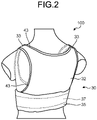
- FIG. 2 is a drawing of one composition example illustrating a backside of the biological signal monitoring wear according to the first embodiment of the present invention.
- FIG. 1 is a drawing of a biological signal monitoring wear 100 according to the first embodiment viewed from a front right oblique direction of a subject who wears this wear.
- FIG. 2 is a drawing of the biological signal monitoring wear 100 according to the first embodiment viewed from a back left oblique direction of the subject who wears this wear.
- the subject means a subject who is subjected to biological signal monitoring, i.e., the subject who wears the biological signal monitoring wear 100 in the first embodiment.
- the biological signal monitoring wear 100 includes a plurality of electrodes 11 to 13, an electrocardiograph 200, an electrically connecting unit 10 that electrically connects these electrodes 11 to 13 to the electrocardiograph 200, and a wear main body 30 that is detachably attached with these components and an instrument and is worn by the subject.
- the electrodes 11 to 13 are one example of electrodes that come into contact with the subject's skin. As illustrated in FIG. 1 , the electrodes 11 to 13 (three in the case of the first embodiment) are arranged on the back surface of the wear main body 30 in such a way that they can be in contact with the subject's skin. Specifically, they are detachably attached to the back surface of the electrically connecting unit 10 that is arranged on the backside of a torso portion 36 in the wear main body 30.
- the number of the electrodes 11 to 13 that are arranged in the biological signal monitoring wear 100 is not limited to three as illustrated in FIG. 1 , but this may also be two or more.
- the arrangement of these electrodes 11 to 13 is not limited to the locations indicated by dashed lines in FIG. 1 . For example, the number and arrangement of the electrodes 11 to 13 are determined in accordance with, among other things, the measurement method of the biological signal to be acquired from the subject.
- the "back surface” means a surface of the skin (body surface) side (the surface facing the skin) of the subject who wears the wear main body 30.
- the “front surface” means a surface that is on an opposite side of the “back surface” mentioned above unless otherwise specifically mentioned.
- the definitions of "back surface” and “front surface” apply to each component of the electrodes 11 to 13, the electrically connecting unit 10, the wear main body 30, etc., that make up the biological signal monitoring wear 100.
- the electrically connecting unit 10 is one example of units that can electrically connect a biological signal measurement instrument (in the case of the first embodiment, the electrocardiograph 200), which measures the subject's biological signal, to the electrodes 11 to 13.
- the electrically connecting unit 10 is arranged on the back surface of the wear main body 30.
- the electrically connecting unit 10 is detachably attached to the back surface of a portion corresponding to the subject's abdomen in the torso portion 36 in the wear main body 30.
- the electrodes 11 to 13 are detachably attached to the back surface of this electrically connecting unit 10.
- the electrocardiograph 200 is detachably attached to the electrically connecting unit 10 from the front side of the wear main body 30, as illustrated in FIG. 1 .
- the electrocardiograph 200 is one example of biological signal measurement instruments that measure the subject's biological signals. As illustrated in FIG. 1 , the electrocardiograph 200 is detachably attached to the electrically connecting unit 10 from the front side of the torso portion 36 in the wear main body 30, and is electrically connected to the electrodes 11 to 13 through the electrically connecting unit 10.
- the electrocardiograph 200 has a function to continuously measure the subject's electrocardiogram signal (one example of biological signals) for a period of two weeks or longer without recharging when a battery thereof is charged in advance, as well as a function to store the obtained electrocardiogram data (electrocardiogram waveform data from the electrocardiogram signal).
- the electrocardiograph 200 have, in addition to these functions, a function to transfer data to a mobile terminal or to a personal computer by communication.
- This function allows, for example, data to be easily transferred and stored in a personal computer from the electrocardiograph 200 so as to perform electrocardiogram analysis of the subject on the basis of the stored data.
- the wear main body 30 is one example of wears to which the electrically connecting unit 10 is detachably attached and worn by the subject. As illustrated in FIGS. 1 and 2 , the wear main body 30 is composed of a front body 31, a back body 32, and shoulder straps 33. Specifically, the front body 31 and the back body 32 are integrally connected to each other by two shoulder straps 33. The front body 31 and the back body 32 are separated at both side portions (corresponding to the flanks of the subject). Both side portions of the front body 31 and the back body 32 are detachably connected, as illustrated in FIG. 1 .
- the front body 31 and the back body 32 be detachably separated at both side portions as described above, but they may also be detachably separated at least at one of both side portions. This makes it easier for the subject to wear the wear main body 30. It is preferable that the front body 31 and the back body 32 be separated at least at one of both side portions, but may be connected at both side portions. It is preferable that the front body 31 and the back body 32 be connected by two shoulder straps 33 as described above, but may be connected by at least one shoulder strap 33. This prevents relative misalignment of the wear main body 30 with the subject under the state that the subject is wearing the wear main body 30.
- the wear main body 30 includes the torso portion 36 that is annular around the subject's waist.
- the torso portion 36 in the wear main body 30 is constructed by connecting a torso portion 34 in the front body 31 to a torso portion 35 in the back body 32.
- the torso portion 34 in the front body 31 is a portion that extends from the front to the side (flank) of the abdomen of the subject who wears the wear main body 30.
- On the surface of the torso portion 34 in the front body 31 is formed a joint portion 40 so as to detachably connect the torso portion 34 in the front body 31 to the torso portion 35 in the back body 32, as illustrated in FIG. 1 .
- a fabric backing sheet with a non-elastic structure is formed by adhering or the like on the back surface of the torso portion 34 of the torso portion 36 in the front body 31 in the wear main body 30.
- the details of this fabric backing sheet will be described later.
- the electrically connecting unit 10 is detachably attached to the back surface portion where the fabric backing sheet is formed, in the torso portion 34 of the front body 31.
- the torso portion 35 in the back body 32 is a portion that extends from the waist to the flank of the subject who wears the wear main body 30.
- the torso portion 35 in the back body 32 includes a side tab 35a at each end.
- the torso portion 35 in the back body 32 is connected to the torso portion 34 in the front body 31 by attaching these side tabs 35a to the joint portion 40 of the torso portion 34 in the front body 31.
- a shrinkable binder tape 43 is sewn around the wear main body 30 to prevent the edges of the cut fabric thereof from unraveling.
- the wear main body 30 includes an elastic body 37 for stretching the torso portion 35 in the back body 32 in accordance with the length of the waist girth of the subject.
- the elastic body 37 is formed inside the torso portion 35 in the back body 32.
- the elastic body 37 is stretched by pulling the torso portion 35 in the back body 32 toward the side tabs 35a.
- the elastic body 37 contracts so that the annularly connected torso portion 34 in the front body 31 and the torso portion 35 in the back body 32 (i.e., the torso portion 36 of the wear main body 30) may be brought into tight contact with the subject's body.
- the fabric of the wear main body 30, i.e., the fabric of the front body 31, the back body 32, and the shoulder straps 33 constituting the wear main body 30, is preferably a fabric having good stretchability such as a two-way tricot or a smooth knit used for underwear, while more preferably a fabric having, in addition to the stretchability, a sweat-absorbing property and a pleasant feeling upon touching.
- a material for the fabric include polyester type synthetic fibers such as polyethylene terephthalate, polytrimethylene terephthalate, and polybutylene terephthalate, as well as polyamide type synthetic fibers such as nylon.
- natural materials such as cotton and hemp may also be used as the material for the fabric.
- FIG. 3A is a drawing of one composition example illustrating an electrode connector side of the electrically connecting unit applied to the biological signal monitoring wear according to the first embodiment of the present invention.
- FIG. 3B is a drawing of one composition example illustrating an instrument connector side of the electrically connecting unit applied to the biological signal monitoring wear according to the first embodiment of the present invention.
- the electrically connecting unit 10 includes a sheet electrical insulator 1, electrode connectors 2a to 2c, instrument connectors 3a to 3d, and lead wires 4a to 4c.
- the electrically connecting unit 10 is a unit integrating the electrode connectors 2a to 2c, the instrument connectors 3a to 3d, and the lead wires 4a to 4c into the sheet electrical insulator 1.
- the electrically connecting unit 10 includes fixing portions 5 and 6 so as to be detachably attached to the wear main body 30.
- the electrical insulator 1 is one example of sheet electrical insulators having flexibility. Specifically, the electrical insulator 1 is constructed by stacking a plurality of electrically insulating sheets. For example, the electrical insulator 1 is formed by overlapping an electrically insulating sheet on the electrode connector side where the electrode connectors 2a to 2c are formed and an electrically insulating sheet on the instrument connector side where the instrument connectors 3a to 3d are formed, followed by bonding these sheets. These two electrically insulating sheets are bonded with each other by the method such as a thermal welding method in which the perimeters of the sheets are adhered using a heat sealer or the like.
- the electrical insulator 1 is flexible enough to be easily bent in response to an external force, and electrically insulates each of the electrode connectors 2a to 2c, the instrument connectors 3a to 3d, and the lead wires 4a to 4c.
- a thermoplastic resin such as polyethylene, polypropylene, vinyl chloride resin, polystyrene, or polyamide, or a foamed body of these resins is preferable, and a cross-linked foamed resin is further preferable.
- the electrode connectors 2a to 2c are examples of a plurality of electrode connectors each connecting the electrodes 11 to 13 that are to be in contact with the subject's skin. As illustrated in FIG. 3A , the electrode connectors 2a to 2c (three in the case of the first embodiment) are formed on a first surface (back surface A1) of both surfaces of the electrical insulator 1 in the thickness direction of the electrical insulator 1. For example, these electrode connectors 2a to 2c are formed on the electrically insulating sheet on the electrode connector side and are arranged so as to be exposed from only the back surface A1 during the manufacturing process of the electrical insulator 1.
- the electrode 11 is electrically connected to the electrode connector 2a
- the electrode 12 is electrically connected to the electrode connector 2b
- the electrode 13 is electrically connected to the electrode connector 2c.
- the number and arrangement of the electrode connectors 2a to 2c in the electrical insulator 1 are determined in according with the number and arrangement of the electrodes 11 to 13.
- the instrument connectors 3a to 3d are one example of instrument connectors that detachably connect the biological signal measurement instruments. As illustrated in FIG. 3B , the instrument connectors 3a to 3d (four in the case of the first embodiment) are formed on a second surface (front surface A2) of both surfaces of the electrical insulator 1 in the thickness direction of the electrical insulator 1. The second surface is a surface that is on an opposite side of the first surface (opposite surface). For example, these instrument connectors 3a to 3d are formed on the electrically insulating sheet on the instrument connector side and are arranged so as to be exposed from only the front surface A2 during the manufacturing process of the electrical insulator 1. In the first embodiment, the electrocardiograph 200 (see FIG.
- the number and arrangement of the instrument connectors 3a to 3d in the electrical insulator 1 are determined in accordance with the number and arrangement of terminals of the electrocardiograph 200.
- the electrode connectors 2a to 2c and the instrument connectors 3a to 3d it is preferable to use, for example, metal dot buttons that have a high corrosion resistance and are applied to devices such as a wearable terminal device and a medical device, and are suitable for measurement of biological signals such as the electrocardiogram signal.
- the electrode connectors 2a to 2c and the instrument connectors 3a to 3d are not limited to those described above, but may be a connector such as a socket that is generally used in connection of a cord.
- the lead wires 4a to 4c are one example of electrical conductors that electrically connect the electrode connectors 2a to 2c to the instrument connectors 3a to 3d.
- the lead wires 4a to 4c (three in the case of the first embodiment) are formed in the electrical insulator 1 in such a way as not to be exposed from any of the back surface A1 and the front surface A2 of the electrical insulator 1.
- these lead wires 4a to 4c are formed so as to be sandwiched between the electrically insulating sheet on the electrode connector side and the electrically insulating sheet on the instrument connector side as described above, and are arranged inside the electrical insulator 1.
- the lead wire 4a electrically connects the electrode connector 2a to the instrument connector 3a
- the lead wire 4b electrically connects the electrode connector 2b to the instrument connector 3c
- the lead wire 4c electrically connects the electrode connector 2c to the instrument connector 3d.
- the lead wires 4a to 4c be formed by the method in which an electrically conductive resin is printed onto a flexible printing board used in an electronic device or onto a thin electrically insulating resin, or other methods. It is more preferable that the lead wires 4a to 4c be formed by a fiber of an electrically conductive metal wire, or the like.
- this electrically conductive fiber may be a metal-covered yarn in which a polyester fiber or a nylon fiber is covered with a metal fiber such as silver, aluminum, or stainless steel, or a composite fiber in which carbon black is composite-arranged in a part of a core or a shell of polyester or nylon in a longitude direction of the fiber, or a metal-coated yarn in which a polyester fiber or a nylon fiber is coated with a metal such as silver, aluminum, or stainless steel.
- the metal-coated yarn is especially preferable.
- a lead wire such as “hitoe (registered trademark) Medical Lead Wire” or “hitoe (registered trademark) Medical Lead Wire II", both being manufactured by Toray Medical Co., Ltd., may be used as the lead wires 4a to 4c.
- the fixing portions 5 and 6 are members for realizing detachable attachment of members relating to the electrically connecting unit 10.
- the fixing portion 5 is a member for detachably connecting a cover member that covers the back surface A1 (the surface facing the subject's skin) of the electrically connecting unit 10 in the state that the electrically connecting unit 10 is attached to the back surface of the front body 31 in the wear main body 30.
- This cover member may be, for example, a unit cover (to be described later) formed on the back surface of the front body 31.
- a plurality (three in the case of the first embodiment) of the fixing portions 5 is formed on the back surface A1 of the electrically connecting unit 10.
- these fixing portions 5 are arranged near the lower end of the back surface A1 when the electrically connecting unit 10 is attached to the back surface of the front body 31.
- a member such as a repeatedly usable urethane adhesive sheet or a touch fastener of a surface A (hook surface) or a surface B (loop surface) may be used.
- the fixing portion 6 is a member for detachably attaching the electrically connecting unit 10 to the back surface of the front body 31 in the wear main body 30.
- a plurality (two in the case of the first embodiment) of the fixing portions 6 is formed on the front surface A2 of the electrically connecting unit 10.
- these fixing portions 6 are located near each of right and left ends of the front surface A2 when the electrically connecting unit 10 is attached to the back surface of the front body 31.
- a member such as a repeatedly usable urethane adhesive sheet or a touch fastener of a surface A (hook surface) or a surface B (loop surface) may be used.
- FIG. 4 is a drawing of one composition example illustrating the front body of the wear main body according to the first embodiment of the present invention.
- FIG. 4 illustrates the front body 31 without attaching the electrically connecting unit 10, viewed from the back side thereof.
- the front body 31 includes a fabric backing sheet 38 to which the electrically connecting unit 10 is to be attached, a unit cover 39 that covers the electrically connecting unit 10, and fixing portions 41.
- the front body 31 also includes side tabs 34a at both ends of the torso portion 34.
- the shrinkable binder tape 43 is sewn around the unit cover 39 in order to prevent the edges of the cut fabric thereof from unraveling.
- the fabric backing sheet 38 is one example of fabric backing sheets having a non-elastic structure that is formed on the portion where the electrically connecting unit 10 can be detachably attached in the torso portion 36 in the wear main body 30 (see FIG. 1 ).
- the fabric backing sheet 38 has a non-elastic structure and is bonded to the back surface of the torso portion 34 of the torso portion 36 in the front body 31 in the wear main body 30, as illustrated in FIG. 4 .
- the non-elastic structure of the fabric backing sheet 38 means a structure that has the properties of being difficult to be stretched or non-stretchable, and also has the property of being able to easily bend (such as flexible structure).
- the fabric backing sheet 38 can be deformed such as bending together with the adhered torso portion 34 in the front body 31, but is less stretchable than the torso portion 34.
- the fixing portion 6 of the electrically connecting unit 10 illustrated in FIG. 3B is detachably connected to the fabric backing sheet 38, so that the electrically connecting unit 10 is detachably attached to the fabric backing sheet 38.
- the fabric backing sheet 38 prevents stretch- or contract-deformation of the torso portion 34 even when the front body 31 stretches or contracts by the movement of the subject or by the action of the elastic body 37 in the back body 32.
- a thick adhesive interlining or a touch fastener may also be used as the fabric backing sheet 38.
- an adhesive member such as a urethane adhesive sheet that can be used repeatedly is used as the fixing portion 6 (see FIG. 3B ) that is attached to the front surface A2 of the electrically connecting unit 10.
- the fabric backing sheet 38 is a touch fastener
- the touch fastener that can be detachably attached to the touch fastener of the fabric backing sheet 38 is used as the fixing portion 6.
- the fixing portion 6 is the touch fastener with the surface B (loop surface).
- the fixing portion 6 is the touch fastener with the surface A (hook surface).
- the touch fastener is used as the fabric backing sheet 38, it is preferable to use the touch fastener with the surface B (loop surface) from the viewpoint of alleviating the discomfort caused by contact with the subject's skin, because the fabric backing sheet 38 faces the skin.
- instrument connector holes 51 to 54 there is a plurality (e.g., four) of instrument connector holes 51 to 54 in the torso portion 34 and the fabric backing sheet 38 in the front body 31.
- These instrument connector holes 51 to 54 are through holes for exposing the instrument connectors 3a to 3d (see FIG. 3B ) of the electrically connecting unit 10 from the fabric backing sheet 38 side to the front surface side of the front body 31 when the electrically connecting unit 10 is attached to the fabric backing sheet 38.
- the fixing portion 6 of the electrically connecting unit 10 is connected to the fabric backing sheet 38 so that the electrically connecting unit 10 is detachably attached to the fabric backing sheet 38.
- the instrument connector 3a is exposed from the instrument connector hole 51 to the front surface side of the front body 31, and the instrument connector 3b is exposed from the instrument connector hole 52 to the front surface side of the front body 31.
- the instrument connector 3c is exposed from the instrument connector hole 53 to the front surface side of the front body 31, and the instrument connector 3d is exposed from the instrument connector hole 54 to the front surface side of the front body 31.
- the number and arrangement of these instrument connector holes 51 to 54 are determined in accordance with the number and arrangement of the instrument connectors 3a to 3d formed in the electrically connecting unit 10.
- the front surface of the torso portion 34 in the front body 31 is provided with the joint portion 40.
- the joint portion 40 is formed by sewing or the like on the surface of the torso portion 34 in the front body 31 at a location spaced from the instrument connector holes 51 to 54 to the side tabs 34a. This ensures that the joint portion 40 is configured so as not to cover the instrument connector holes 51 to 54.
- the unit cover 39 is one example of fabric members covering a portion of the back surface A1 (first surface) of the electrical insulator 1 in the electrically connecting unit 10 other than the electrode connectors 2a to 2c (see FIG. 3A ). As illustrated in FIG. 4 , the unit cover 39 is sewn to the back surface of the torso portion 34 in the front body 31 such that this can open and close the portion where the electrically connecting unit 10 is attached in the back surface of the front body 31 (specifically, the portion to which the fabric backing sheet 38 is adhered).
- the unit cover 39 includes a fixing portion 41 and electrode connector holes 57 to 59.
- the fixing portion 41 is a member for detachably connecting the unit cover 39 to the electrically connecting unit 10 that is attached to the back surface of the front body 31 in the wear main body 30.
- a plurality (three in the case of the first embodiment) of the fixing portions 41 is formed on the unit cover 39.
- the number and arrangement of the fixing portion 41 are determined in accordance with the number and arrangement of the fixing portion 5 (see FIG. 3A ) attached to the back surface A1 of the electrically connecting unit 10.
- a member such as a touch fastener with a surface A (hook surface) or with a surface B (loop surface) may be used.
- the fixing portion 5 in the electrically connecting unit 10 is the touch fastener with the surface A (hook surface)
- the fixing portion 5 of the electrically connecting unit 10 is the touch fastener with the surface B (loop surface).
- the fixing portion 5 of the electrically connecting unit 10 is the touch fastener with the surface A (hook surface).
- the electrode connector holes 57 to 59 are through holes that can expose the electrode connectors 2a to 2c (see FIG. 3A ) in the electrically connecting unit 10 attached to the fabric backing sheet 38 from the unit cover 39. Specifically, the electrode connector hole 57 exposes the electrode connector 2a from the unit cover 39. The electrode connector hole 58 exposes the electrode connector 2b from the unit cover 39. The electrode connector hole 59 exposes the electrode connector 2c from the unit cover 39. The number and arrangement of these electrode connector holes 57 to 59 are determined in accordance with the number and arrangement of the electrode connectors 2a to 2c formed in the electrically connecting unit 10.
- FIG. 5 is a drawing of one composition example illustrating the front body under the state of being attached with the electrically connecting unit according to the first embodiment of the present invention.
- the unit cover 39 closes the electrically connecting unit 10 that is attached to the fabric backing sheet 38, and thereby covering the back surface A1 of the electrically connecting unit 10 other than the electrode connectors 2a to 2c.
- the fixing portions 41 of the unit cover 39 are detachably connected to the fixing portions 5 formed on the back surface A1 of the electrically connecting unit 10.
- the unit cover 39 covers the electrically connecting unit 10 in the way as described above, so that it is possible to prevent the electrically connecting unit 10 from contacting with the subject's skin.
- the unit cover 39 does not only cover the back surface A1 of the electrically connecting unit 10 as described above, but also supports the electrically connecting unit 10 between this and the fabric backing sheet 38. By so doing, the unit cover 39 can prevent not only the electrically connecting unit 10 from being misaligned with the fabric backing sheet 38 but also the electrically connecting unit 10 from falling from the torso portion 34 in the front body 31.
- the electrodes 11 to 13 that are in contact with the subject's skin are electrically connected to the electrically connecting unit 10, which is under the state of being covered by the unit cover 39.
- the electrode 11 is detachably connected to the electrode connector 2a in the electrically connecting unit 10 through the electrode connector hole 57 in the unit cover 39.
- the electrode 12 is detachably connected to the electrode connector 2b in the electrically connecting unit 10 through the electrode connector hole 58 in the unit cover 39.
- the electrode 13 is detachably connected to the electrode connector 2c in the electrically connecting unit 10 through the electrode connector hole 59 in the unit cover 39.
- the electrodes 11 to 13 are arranged in accordance with CC5, which is one of the induction methods of the Holter electrocardiography.
- the electrode 11 is a positive electrode
- the electrode 12 is a ground electrode
- the electrode 13 is a negative electrode.
- the electrodes 11 to 13, which detect the biological signal such as the electrocardiogram signal from the subject's body are, for example, structural bodies formed of an electrically conductive fiber (i.e., electrically conductive fiber structural body).
- the electrically conductive fiber is preferably a fiber that is impregnated with an electrically conductive substance. More preferably, the electrically conductive fiber structural body is made of multi-filaments, and an electrically conductive polymer is supported onto the surfaces of monofilaments as well as in the space formed between the monofilaments, which constitute this electrically conductive fiber structural body.
- the electrically conductive substance there is no particular restriction in the electrically conductive substance to be used in the electrodes 11 to 13 as far as this substance is a compound having an electric conductivity.
- the electrically conductive substance include electrically conductive polymers such as PEDOT/PSS and an electrically conductive substance blended with carbon black, CNT (carbon nanotube), and metal particulate.
- the electrically conductive substance When a substance having an elastic property such as an elastomer resin is used as the electrically conductive substance, the electric conductivity changes depending on the elastic condition of the substance. Thus, stable detection of the biological signal from the subject is difficult. Therefore, the substance having the elasticity is not suitable as the electrically conductive substance.
- the electrically conductive polymer to be used for the electrodes 11 to 13 described above is an electrically conductive polymer that a resin itself is electrically conductive.
- the electrically conductive polymer is more preferably PEDOT/PSS in which a thiophene-type electrically conductive polymer PEDOT is doped with polystyrene sulfonic acid (poly(4-styrene sulfonate) (PSS)).
- PSS poly(4-styrene sulfonate)
- a polymer such as a urethane-type polycarbonate or a urethane-type polyether may be used as the binder.
- Illustrative examples of the form of the electrically conductive fiber structural body to be used for the electrodes 11 to 13 include: textile bodies such as a knitted body, a woven body, and an unwoven cloth; and a strap body. Among these, a knitted body or a woven body is preferably used.
- Fiber materials for the electrically conductive fiber structural body to be used in the present invention are synthetic fibers and the like.
- the synthetic fiber include: fibers formed of polyethylene terephthalate, polypropylene terephthalate, or polybutylene terephthalate; aromatic polyester type fibers formed by copolymerizing these polymers with a third component; aliphatic polyester type fibers represented by those formed of L-lactic acid as a main component therein; polyamide type fibers such as nylon 6 and nylon 66; acrylic fibers formed of polyacrylonitrile as a main component therein; polyolefin type fibers such as polyethylene and polypropylene; and polyvinyl chloride type fibers.
- a fiber blended with an additive such as titanium oxide, and a fiber having a polymer that is reformed so as to be provided with functionality such as an enhanced moisture-absorption property may also be used as the fiber materials.
- the electrically conductive fiber structural body according to the present invention include multi-filaments whose monofilament fiber diameter is 0.2 dtex or less.
- the mixing rate of the multi-filaments whose monofilament fiber diameter is 0.2 dtex or less in the fiber structural body is not particularly restricted as far as the performance thereof is not affected. In view of electric conductivity and durability, preferably the mixing rate is higher, and more preferably the mixing rate is in the range of 50% or higher to 100% or less.
- these electrodes 11 to 13 are made of the fiber structural body that is impregnated with an electrically conductive material, it is preferable that these electrodes 11 to 13 be composed of microfibers having a fiber diameter of 5 ⁇ m or less, like the fiber structural body used in an artificial leather, an outer material, or the like. In particular, it is more preferable that these electrodes 11 to 13 be composed of nanofibers having a fiber diameter of 10 nm or more to 5000 nm or less.
- the fiber structural body including nanofibers produced by a known method such as a nanofiber staple yarn aggregate produced from "Nanoalloy (registered trade mark)" fiber and a monofilament yarn aggregate produced by an electrospinning method, may be preferably used as the nanofiber that constitutes the electrodes 11 to 13.
- the fiber structural body containing multifilament yarns of the nanofibers is particularly preferable for this fiber structural body.
- the nanofiber multifilament yarn may be produced by a known conjugate spinning method or the like.
- a nanofiber multifilament yarn having a small fluctuation in the fiber diameter that is obtained by removing a sea portion of a conjugate fiber using a conjugate spinneret may be effectively used, as illustrated in Japanese Patent Application Laid-open No. 2013-185283 ; but the present invention is not limited to these.
- the electrodes 11 to 13 described above are not limited to those made of the electrically conductive fiber, but may also be those provided with an electrically conductive sheet such as an adhesive film containing an electrically conductive substance. In this case, it is preferable that the electrically conductive sheet that constitute each of the electrodes 11 to 13 have an adhesion strength of 200 g/20 mm or less as measured by the 90-degree peeling method in accordance with JIS-Z0237.
- the size and shape of the electrodes 11 to 13 are not particularly specified as far as the biological signal can be detected.
- the length and width of these electrodes 11 to 13 are preferably in the range of 2.0 cm or more to 5.0 cm or less.
- illustrative examples of the electrodes 11 to 13 that can be used include "hitoe (registered trademark) Medical Electrode” and “hitoe (registered trademark) Medical Electrode II", manufactured by Toray Medical Co., Ltd.
- the side tab 34a in the front body 31 as illustrated in FIG. 4 is a portion corresponding to the subject's flank and is connected to the torso portion 35 in the back body 32 so as to be overlapped with each other.
- the torso portion 35 in the back body 32 is detachably connected to the joint portion 40 formed on the front surface of the front body 31.
- the torso portion 34 in the front body 31 and the torso portion 35 in the back body 32 are annularly connected to form the torso portion 36 in the wear main body 30 (see FIG. 1 ).
- FIG. 6 is a drawing of one composition example illustrating the back body of the wear main body according to the first embodiment of the present invention.
- the back body 32 includes a dorsal portion 32a, the torso portion 35, the elastic body 37, and a joint portion 42.
- the back body 32 includes the side tabs 35a at both ends of the torso portion 35.
- the dorsal portion 32a is a portion corresponding to the back of the subject who wears the wear main body 30. As illustrated in FIG. 6 , the dorsal portion 32a is integrally connected to the front body 31 by means of one or more (two in the case of the first embodiment) shoulder straps 33. The lower end of the dorsal portion 32a (the end opposite to the shoulder strap 33) includes the torso portion 35.
- the torso portion 35 is connected to the torso portion 34 of the front body 31 to form the torso portion 36 of the wear main body 30 (see FIGS. 1 and 2 ) annularly around the subject's waist. As illustrated in FIG. 6 , the torso portion 35 is band-shaped and located at the lower end of the dorsal portion 32a.
- the torso portion 35 is formed, for example, as a stretchable, hollow band and includes the elastic body 37 inside thereof.
- the torso portion 35 which is band-shaped, includes the side tabs 35a at both ends thereof and the joint portion 42 on the back surface of the side tabs 35a.
- the elastic body 37 provides elasticity (stretching force) to the torso portion 35 in the back body 32, which is stretchable in the longitudinal direction of the band.
- the elastic body 37 is formed in the torso portion 36 so as to be longitudinal in the circumferential direction of the torso portion 36 that forms an annularity in the wear main body 30, as illustrated in FIG. 2 .
- the elastic body 37 is incorporated into the torso portion 35 of the band-shaped torso portion 36 in the back body 32 so as to be longitudinal in the longitudinal direction of the torso portion 35.
- the length of the elastic body 37 is in the range of 30% or more to 60% or less relative to the length of the waist girth in the longitudinal direction in the subject's solar plexus portion.
- the electrodes 11 to 13 (see FIG. 5 ) attached to the back surface of the wear main body 30 can be brought into contact with the subject's skin with an appropriate pressure.
- the biological signal can be acquired from the subject through the electrodes 11 to 13 without giving the subject a sense of an excessively high pressure due to wearing of the wear main body 30.
- the elastic body 37 have a length (width) of 25 mm or more to 50 mm or less in the direction perpendicular to the longitudinal direction thereof.
- the elastic body 37 do not change over a long time in the stress and strain characteristics thereof.
- a flat rubber having a width of 40 mm is used as the elastic body 37.
- Polyurethane, a natural rubber, or the like is used as a material for the elastic body 37.
- the force to expand the elastic body 37 by 30% in the longitude direction thereof is preferably in the range of 3N or more to 9N or less.
- 30%-expansion force of the elastic body 37 is less than 3 N, the pressure to the subject's skin is so low that there may be an unintended release of the contact of the subject's skin to the electrodes 11 to 13 thereby bringing about a risk that it may be difficult to obtain the biological signal.
- the 30%-expansion force of the elastic body 37 is greater than 9 N, the compression force may be felt too strong by the subject when wearing the wear main body 30; so, the comfort of wearing the wear main body 30 is lost, resulting in the deterioration of the wearing comfort of the wear main body 30.
- the force to expand the elastic body 37 by 20% in the longitude direction thereof is preferably in the range of 2 N or more to 6 N or less.
- the rate of the increase in the force required when the elastic body 37 is expanded from 10% expansion to 30% expansion in the longitudinal direction thereof is preferably in the range of 0.1 N/% or more to 0.2 N/% or less.
- Illustrative examples of the elastic body 37 described above include LY-40, manufactured by Kitani Co., Ltd.
- the joint portion 42 is a member for connecting the torso portion 35 in the back body 32 to the torso portion 34 in the front body 31.
- the joint portion 42 is composed of a detachable adhesive member such as a touch fastener, in which this is formed by sewing the member to the back surface of the torso portion 35 in the back body 32 (specifically, to the back surface of the side tab 35a in the torso portion 35), as illustrated in FIG. 6 .
- the joint portion 42 is detachably connected to the joint portion 40 (see FIG. 1 ) formed on the front surface of the torso portion 34 in the front body 31.
- the joint portion 40 in the front body 31 is the touch fastener with the surface B (loop surface).
- the joint portion 40 in the front body 31 is the touch fastener with the surface A (hook surface).
- the torso portion 35 in the back body 32 is stretched together with the elastic body 37 according to the length of the waist girth such as the subject's abdominal circumference, and is annularly connected to the torso portion 34 in the front body 31 by connection of the joint portions 40 and 42 with each other.
- the joint portion 42 in the back body 32 and the joint portion 40 in the front body 31 function as size adjustment functional portions that allow the circumferential size of the torso portion 36 of the wear main body 30 to be adjusted according to the length of the subject's waist.
- the electrode connectors 2a to 2c, the instrument connectors 3a to 3d, and the lead wires 4a to 4c are integrated into the sheet electrical insulator 1 to form the electrically connecting unit 10, which is flexible and bendable, so that the electrically connecting unit 10 is detachably attached to the wear main body 30 that is worn by the subject, and also, the electrodes 11 to 13 to be in contact with the subject's skin and the biological signal measurement instrument (for example, electrocardiograph 200) to measure the subject's biological signal are each detachably attached to the electrode connectors 2a to 2c and to the instrument connectors 3a to 3d of the electrically connecting unit 10.
- the biological signal measurement instrument for example, electrocardiograph 200
- conduction wiring between the electrodes 11 to 13 and the biological signal measurement instrument can be formed without an error, so that the biological signal monitoring wear 100 can be conveniently prepared by attaching the electrically connecting unit 10, the electrodes 11 to 13, and the biological signal measurement instrument to the wear main body 30.
- the electrically connecting unit 10 can be flexibly deformed, and also the contact of the electrodes 11 to 13 with the subject's skin can be retained.
- the subject's feeling of wrongness and discomfort due to the electrically connecting unit 10 can be alleviated, thereby making the biological signal monitoring wear 100 comfortable upon wearing, while at the same time allowing the subject engaged in a daily life to conveniently continue to measure the biological signal stably with less noise to the extent that diagnosis of a disease such as the electrocardiogram analysis can be performed over a long period of time such as one week or longer without forcing an excessive tensile stress to the lead wires 4a to 4c in the electrically connecting unit 10.
- the wear main body 30 even when the wear main body 30 is replaced due to sweat or dirt, the subject himself can easily detach the electrically connecting unit 10, the electrodes 11 to 13, and the biological signal measurement instrument from the wear main body 30.
- This allows the subject to wear the biological signal monitoring wear 100 having been replaced with a clean wear main body 30 and to wash the wear main body 30 having been taken off.
- the biological signal can be measured comfortably for the subject under the clean condition of the biological signal monitoring wear 100.
- the electrically connecting unit 10, the electrodes 11 to 13, and the biological signal measurement instrument can be easily attached to and detached from the wear main body 30, not only the cost required for manufacturing the biological signal monitoring wear 100 can be reduced as compared with those in which the components such as the wiring and the electrodes are fixed to the wear, but also the cost required for preparation of the wear main body 30 for replacement can be reduced. Accordingly, the biological signal monitoring wear 100 can be provided inexpensively to many subjects.
- the elastic body 37 is formed in the torso portion 36 in the wear main body 30 so that the torso portion 36 can be stretched and contracted together with the elastic body 37 in the subject's waist circumference direction.
- FIG. 7 is a drawing of one composition example illustrating the biological signal monitoring wear according to the second embodiment of the present invention.
- FIG. 7 illustrates a front body 31A of a wear main body 30A, which is one composition portion of a biological signal monitoring wear 100A according to the second embodiment, viewed from the back surface thereof.
- the biological signal monitoring wear 100A according to the second embodiment includes the wear main body 30A in place of the wear main body 30 of the biological signal monitoring wear 100 according to the first embodiment described above, and an electrically connecting unit 20 in place of the electrically connecting unit 10.
- the wear main body 30A includes the front body 31A in place of the front body 31 in the wear main body 30 in the first embodiment.
- Other components are the same as those in the first embodiment, and the same tags are attached to the same components.
- a subject means a subject who wears the biological signal monitoring wear 100A according to the second embodiment.
- the electrically connecting unit 20 having a cover portion 25 is detachably attached to the back surface of the torso portion 34 in the front body 31A.
- the electrodes 11 to 13 that are to be in contact with the subject's skin are detachably attached to the electrically connecting unit 20.
- the electrocardiograph 200 (see FIG. 1 ), which is one example of biological signal measuring instruments, is detachably attached to the front surface of the front body 31A so as to be connected to the electrodes 11 to 13 through the electrically connecting unit 20, as in the case of the first embodiment.
- the front body 31A is integrally connected to the back body 32 (see FIG. 2 ) by means of two shoulder straps 33.
- FIG. 8A is a drawing of one composition example illustrating the electrode connector side of the electrically connecting unit applied to the biological signal monitoring wear according to the second embodiment of the present invention.
- FIG. 8B is a drawing of one composition example illustrating the instrument connector side of the electrically connecting unit applied to the biological signal monitoring wear according to the second embodiment of the present invention.
- the electrically connecting unit 20 includes a sheet electrical insulator 21, electrode connectors 22a to 22c, instrument connectors 23a to 23d, lead wires 24a to 24c, and the cover portion 25.
- the electrically connecting unit 20 is a unit integrating the electrode connectors 22a to 22c, the instrument connectors 23a to 23d, and the lead wires 24a to 24c into the sheet electrical insulator 21.
- the electrically connecting unit 20 includes fixing portions 26 and 27 so as to be detachably attached to the wear main body 30A.
- the electrical insulator 21 is one example of flexible sheet electrical insulators.
- FIG. 9 is a drawing of one composition example illustrating the sheet electrical insulator applied to the electrically connecting unit according to the second embodiment of the present invention.
- the electrical insulator 21 is configured so as to be a flexible and bendable sheet form by means of a flexible electrically insulating board or the like.
- the lead wires 24a to 24c and terminals 28a to 28c and 29a to 29d are formed in the electrical insulator 21, as illustrated in FIG. 9 .
- the lead wire 24a is formed so as to electrically connect the terminal 28a to the terminal 29a.
- the lead wire 24b is formed so as to electrically connect the terminal 28b to the terminal 29c.
- the lead wire 24c is formed so as to electrically connect the terminal 28c to the terminal 29d.
- the terminals 28a to 28c are terminals for electrically connecting the electrode connectors 22a to 22c, respectively.
- the terminals 29a to 29d are terminals for electrically connecting the instrument connectors 23a to 23d, respectively.
- the electrical insulator 21 is fabricated using a polyester film as the base film board by forming an electrically insulating protective film on this base film board to protect the lead wires 24a to 24c. This protective film is formed on the board surface of the base film board that constitutes the electrical insulator 21 other than the terminals 28a to 28c and 29a to 29d.
- the electrical insulator 21 is flexible enough to be bent easily in response to an external force, and electrically insulates among the electrode connectors 22a to 22c, the instrument connectors 23a to 23d, and the lead wires 24a to 24c, as illustrated in FIGS. 8A and 8B .
- the electrode connectors 22a to 22c are one example of electrode connectors to which the electrodes 11 to 13 that are to be in contact with the subject's skin are connected. As illustrated in FIG. 8A , the electrode connectors 22a to 22c (three in the case of the second embodiment) are formed, of both surfaces of the electrical insulator 21 in the thickness direction, on the back surface A1. For example, these electrode connectors 22a to 22c are each formed to the terminals 28a to 28c of the electrical insulator 21 as illustrated in FIG. 9 , and are configured so as to be exposed from only the back surface A1 of the electrical insulator 21.
- the electrodes 11 to 13 are electrically and detachably connected to the electrode connectors 22a to 22c, respectively, in the same manner as in the first embodiment (see FIG. 7 ).
- the number and arrangement of the electrode connectors 22a to 22c in the electrical insulator 21 are determined in according with the number and arrangement of the electrodes 11 to 13.
- the instrument connectors 23a to 23d are one example of instrument connectors that detachably connect the biological signal measurement instrument. As illustrated in FIG. 8B , a plurality (four in the case of the second embodiment) of the instrument connectors 23a to 23d are formed, of both surfaces of the electrical insulator 21 in the thickness direction, on a surface A2. For example, the instrument connectors 23a to 23d are each formed to the terminals 29a to 29d of the electrical insulator 21 as illustrated in FIG. 9 , and are configured so as to be exposed only from the surface A2 of the electrical insulator 21. As in the case of the first embodiment, the electrocardiograph 200 (see FIG.
- the number and arrangement of the instrument connectors 23a to 23d in the electrical insulator 21 are determined in accordance with the number and arrangement of the terminals of the electrocardiograph 200.
- the electrode connectors 22a to 22c and the instrument connectors 23a to 23d are not limited to those described above, but may be a connector such as a socket that is generally used in connection of a cord.
- the lead wires 24a to 24c are one example of electrical conductors that electrically connect the electrode connectors 22a to 22c to the instrument connectors 23a to 23d. As illustrated in FIGS. 8A and 8B , the lead wires 24a to 24c (three in the case of the second embodiment) are covered, for example, by the electrical insulator 21, which is a protective film, and are not exposed from any of the back surface A1 and the front surface A2 of the electrical insulator 21. It is preferable that the lead wires 24a to 24c be wired, for example, by printing an electrically conductive resin on the surface of the electrical insulator 21.
- the lead wire 24a electrically connects the electrode connector 22a to the instrument connector 23a
- the lead wire 24b electrically connects the electrode connector 22b to the instrument connector 23c
- the lead wire 24c electrically connects the electrode connector 22c to the instrument connector 23d.
- the cover portion 25 is a component to avoid the direct contact between the subject's skin and the electrically connecting unit 20.
- the cover portion 25 is made of, for example, the same fabric material as that of the wear main body 30, and is formed on the first surface (back surface A1) of the electrical insulator 21 in the electrically connecting unit 20. Specifically, as illustrated in FIGS. 8A and 8B , the cover portion 25 is adhered to the back surface A1 of the electrical insulator 21 so as to cover the portion of the back surface A1 other than the electrode connectors 22a to 22c.
- the fixing portions 26 and 27 are members for detachably attaching the electrically connecting unit 20 to the back surface of the front body 31A of the wear main body 30A.
- the fixing portions 26 are each formed on a portion corresponding to the electrode connectors 22a to 22c in the front surface A2 of the electrically connecting unit 20.
- the fixing portion 27 is formed on a portion corresponding to the instrument connectors 23a to 23d in the front surface A2 of the electrically connecting unit 20.
- a member such as a repeatedly usable urethane adhesive sheet or a touch fastener with a surface A (hook surface) or with a surface B (loop surface) may be used.
- FIG. 10 is a drawing of one composition example illustrating the front body of the wear main body according to the second embodiment of the present invention.
- FIG. 10 illustrates the front body 31A without attaching the electrically connecting unit 20, viewed from the back side thereof.
- the front body 31A includes the fabric backing sheet 38, the side tabs 34a, and the joint portions 40 in the torso portion 34, as in the case of the first embodiment.
- the front body 31A is not provided with the unit cover 39 and the fixing portion 41 as in the case of the first embodiment.
- the binder tape 43 is sewn around the wear main body 30A in the second embodiment to prevent the edges of the cut fabric from unraveling, as in the case of the first embodiment.
- the fixing portions 26 and 27 (see FIG. 8B ) in the electrically connecting unit 20 are detachably connected to the fabric backing sheet 38 illustrated in FIG. 10 , so that the electrically connecting unit 20 is detachably attached to the fabric backing sheet 38.
- this fabric backing sheet 38 thick adhesive interlining or a touch fastener may be used, as in the case of the first embodiment.
- an adhesive member such as a urethane adhesive sheet that can be used repeatedly is used as the fixing portions 26 and 27 that are attached to the surface A2 of the electrically connecting unit 20.
- the touch fastener that can be detachably attached to the touch fastener of the fabric backing sheet 38 is used as the fixing portions 26 and 27.
- the fixing portions 26 and 27 are a touch fastener with a surface B (loop surface).
- the fixing portions 26 and 27 are a touch fastener with a surface A (hook surface).
- the cover portion 25 of the electrically connecting unit 20 is interposed between the skin of the subject who wears the biological signal monitoring wear 100A and the electrically connecting unit 20.
- the cover portion 25 prevents the direct contact between the subject's skin and the electrically connecting unit 20.
- the cover portion 25 eliminates the subject's discomfort due to the contact of the skin with the electrically connecting unit 20.
- the fixing portions 26 and 27 of the electrically connecting unit 20 are connected to the fabric backing sheet 38 after the instrument connectors 23a to 23d and the instrument connector holes 51 to 54 are aligned with each other.
- the cover portion 25 is formed on the back surface A1 of the electrically connecting unit 20, and the cover portion 25 is interposed between the electrically connecting unit 20, which is detachably attached to the fabric backing sheet 38 on the back surface of the wear main body 30A by means of the fixing portions 26 and 27, and the subject's skin, while the other components are the same as those in the first embodiment. Therefore, not only the same action effects as those in the first embodiment described above can be enjoyed, but also the operation required to sew the unit cover 39 to the back surface of the front body 31A in the wear main body 30A can be eliminated. As a result, the wear main body 30A can be made more easily than in the case of the first embodiment, so that the cost required for manufacturing the biological signal monitoring wear 100A as well as the cost required for preparation can be reduced furthermore.
- FIG. 11 is a drawing of one composition example illustrating the biological signal monitoring wear according to the third embodiment of the present invention.
- FIG. 11 is a drawing of a biological signal monitoring wear 100B according to the third embodiment, viewed from the front surface side (front side) thereof.
- FIG. 12 is a drawing of one composition example illustrating a back body of a wear main body applied to the biological signal monitoring wear according to the third embodiment of the present invention.
- the biological signal monitoring wear 100B according to the third embodiment includes a wear main body 30B instead of the wear main body 30 of the biological signal monitoring wear 100 according to the first embodiment.
- the wear main body 30B according to the third embodiment includes a front body 31B in place of the front body 31 in the wear main body 30 according to the first embodiment, a back body 32B in place of the back body 32, and shoulder straps 33A in place of the shoulder straps 33.
- the front body 31B of the wear main body 30B includes a unit storage body 60 in place of the torso portion 34 in the front body 31 in the first embodiment.
- an electrically connecting unit in the third embodiment is stored such that this can be taken out from and put in the unit storage body 60 in place of the electrically connecting unit 10 in the first embodiment.
- the electrocardiograph 200 (see FIG. 1 ), which is one example of biological signal measurement instruments, is detachably attached to the front surface of the unit storage body 60.
- the back body 32B of the wear main body 30B includes a band-shaped (belt-shaped) elastic body 37A in place of the torso portion 35 and the elastic body 37 in the back body 32 of the first embodiment.
- Other components are the same as those in the first embodiment, and the same tags are attached to the same components.
- a subject means a subject who wears the biological signal monitoring wear 100B according to the third embodiment.
- the front body 31B is integrally connected to the back body 32B by means of two shoulder straps 33A, as illustrated in FIG. 11 .
- the unit storage body 60 is formed, as illustrated in FIG. 11 .
- the unit storage body 60 has a bag-shaped structure that is long in the direction of the subject's waist girth and stores the electrically connecting unit in the third embodiment such that this can be taken out and put in. The electrically connecting unit in the third embodiment will be described later.
- the unit storage body 60 includes the same instrument connector holes 51 to 54 as those of the first embodiment, as well as a pair of belt loops 61 and a pair of loop tapes 62.
- the instrument connector holes 51 to 54 are formed on a portion where the electrocardiograph 200 is attached in the surface of the unit storage body 60.
- the belt loops 61 are formed at each end of the unit storage body 60 in the longitudinal direction by sewing or the like.
- the loop tapes 62 are each formed by sewing or the like on the surface of the unit storage body 60 such that they are located between the instrument connector holes 51 to 54 and the belt loop 61.
- the belt loops 61 and the loop tapes 62 are formed preferably symmetrically with respect to the longitudinal center position of the unit storage body 60.
- the back body 32B includes a dorsal portion 32b that is integrated with the front body 31B by means of two shoulder straps 33A, as illustrated in FIGS. 11 and 12 .
- the back body 32B does not have the torso portion 35 in the back body 32 in the first embodiment, but includes the belt-shaped elastic body 37A.
- the elastic body 37A is a belt-shaped stretchable member that is long in the circumferential direction around the subject's waist girth, and is sewn directly to the lower end portion of the dorsal portion 32b of the back body 32B (the end portion opposite to the shoulder strap 33A), as illustrated in FIG. 12 .
- a hook 63 is formed, as illustrated in FIGS.
- the hook 63 is a member for detachably connecting the elastic body 37A in the state of being stretched in accordance with the length of the subject's waist girth to the unit storage body 60 of the front body 31B.
- the hook 63 is connected to the elastic body 37A by a hook attachment tape 64.
- the elasticity characteristics and material of the elastic body 37A in the third embodiment are the same as those of the elastic body 37 in the first embodiment.
- FIG. 13A is a drawing of one composition example illustrating the unit storage body that is attached to the front body of the wear main body according to the third embodiment of the present invention.
- FIG. 13A illustrates an enlarged view of the unit storage body 60 illustrated in FIG. 11 viewed from the front surface side (front side).
- FIG. 13B is an enlarged view of one composition example illustrating the loop tape of the unit storage body illustrated in FIG. 13A .
- One loop tape 62 of a pair of loop tapes 62 is illustrated in FIG. 13B .
- a pair of the belt loops 61 and a pair of the loop tapes 62 are each sewn to the surface of the unit storage body 60, for example, in a symmetrical position across the instrument connector holes 51 to 54.
- Each of the loop tapes 62 includes a plurality of loops 69 that are equally spaced from the side of the longitudinal center of the unit storage body 60 (the side of the instrument connector holes 51 to 54 in FIG. 13A ) toward the side of the longitudinal end of the unit storage body 60 (the side of the belt loop 61 in FIG. 13A ).
- 11 loops 69 are formed in each of the loop tapes 62 with an interval of 1 cm from the side of the instrument connector holes 51 to 54 toward the side of the belt loop 61.
- the unit storage body 60 is formed with a fabric backing sheet having a non-elastic structure to prevent stretch- or contract-deformation of the unit storage body 60 due to the elasticity (elastic force) of the elastic body 37A.
- this fabric backing sheet is attached to the inner surface of the fabric that makes up the bag-shaped unit storage body 60.
- the adhesive interlining or the like having a smooth surface is used as the fabric backing sheet so as to allow smooth loading and unloading of the electrically connecting unit to and from the unit storage body 60.
- connection of the elastic body 37A to the unit storage body 60 is realized by passing each side of the elastic body 37A through the belt loops 61 and then hanging the hooks 63 of the elastic body 37A to the loops 69 of the loop tapes 62.
- the wear of the size M is used as the wear main body 30B that is suitable for this subject.
- the loop tapes 62 each have 11 loops 69, each of which corresponds to the size from 80 cm to 100 cm.
- the left side hook 63 of the hooks 63 in both sides of the elastic body 37A is hung by insertion or the like to the "88 cm” loop 69 in the left side loop tape 62 of the loop tapes 62.
- the remaining right side hook 63 is hung by insertion or like to the "88 cm” loop 69 in the remaining left side loop tape 62.
- the "88 cm” loop 69 is the fifth loop from the side of the instrument connector holes 51 to 54 (connector hole side) to the side of the belt loop 61 (belt loop side).
- the left side hook 63 of the hooks 63 in both sides of the elastic body 37A is hung by insertion or the like to the "86 cm” loop 69 in the left side loop tape 62 of the loop tapes 62.
- the remaining right side hook 63 is hung by insertion or like to the "84 cm” loop 69 in the remaining left side loop tape 62.
- the "86 cm” loop 69 is the fourth loop from the connector hole side to the belt loop side.
- the "84 cm” loop 69 is the third loop from the connector hole side to the belt loop side.
- the order in which the hooks 63 on both sides of the elastic body 37A are hung may be from the right side, from the left side, or from both sides at the same time.
- FIG. 14 is a drawing of one composition example illustrating the back surface of the front body in the wear main body according to the third embodiment of the present invention.
- FIG. 14 illustrates the front body 31B of the biological signal monitoring wear 100B in the third embodiment not attached with the electrically connecting unit, which is viewed from the back surface side.
- the bag-shaped unit storage body 60 is attached to the lower end of the front body 31B (the end opposite to the shoulder strap 33A) by sewing or the like.
- On the back surface of the unit storage body 60 there is a plurality (three in the case of FIG. 14 ) of electrode holes 65 to 67.
- the unit storage body 60 includes a unit loading/unloading port 68 at one end of its longitudinal direction.
- the unit loading/unloading port 68 is an opening for loading and unloading the electrically connecting unit to/from the unit storage body 60.
- the unit storage body 60 detachably stores the electrically connecting unit by insertion thereof through the unit loading/unloading port 68. The stored electrically connecting unit can be easily taken out from the unit storage body 60 through the unit loading/unloading port 68.
- FIG. 15A is a drawing of one composition example illustrating the electrode connector side of the electrically connecting unit applied to the biological signal monitoring wear according to the third embodiment of the present invention.
- FIG. 15B is a drawing of one composition example illustrating the instrument connector side of the electrically connecting unit applied to the biological signal monitoring wear according to the third embodiment of the present invention.
- an electrically connecting unit 10A in the third embodiment has the same composition as the electrically connecting unit 10 in the first embodiment (see FIGS. 3A and 3B ), except for the composition to be described below.
- the electrically connecting unit 10A in the third embodiment includes the electrodes 11 to 13 that have been connected to the electrode connectors 2a to 2c, respectively, in advance.
- the electrically connecting unit 10A does not have the fixing portion 5 of the first embodiment on the back surface A1 (electrode side) and the fixing portion 6 of the first embodiment on the front surface A2 (instrument connector side). By omitting these fixing portions 5 and 6, the electrically connecting unit 10A can be smoothly put in and taken out from the unit storage body 60.
- the electrode holes 65 to 67 are formed on the back surface of the unit storage body 60. Therefore, the electrically connecting unit 10A can be put in and taken out from the unit storage body 60 without detaching the electrodes 11 to 13.
- the electrically connecting unit 10A is inserted into and stored inside the unit storage body 60 through the unit loading/unloading port 68 (see FIG. 14 ).
- the electrodes 11 to 13 of the electrically connecting unit 10A illustrated in FIG. 15A are exposed to the back surface of the wear main body 30B (specifically, the back surface side of the unit storage body 60) through the electrode holes 65 to 67 (see FIG. 14 ) from the inner surface side of the unit storage body 60.
- the instrument connectors 3a to 3d of the electrically connecting unit 10A illustrated in FIG. 15B are exposed to the front surface side of the wear main body 30B (specifically, the front surface side of the unit storage body 60) through the instrument connector holes 51 to 54 (see FIG. 11 ) from the inner surface side of the unit storage body 60.
- the electrocardiograph 200 (see FIG. 1 ) is connected as in the case of the first embodiment.
- the electrically connecting unit 10A is detachably attached inside the unit storage body 60, while the electrodes 11 to 13 to be in contact with the subject's skin are electrically connected to the electrocardiograph 200.
- the front body 31B, the back body 32B (especially the dorsal portion 32b), and the shoulder straps 33A constituting the wear main body 30B are formed of so-called free-cut fabrics that can be used in the as-cut state. These free-cut fabrics may also be used for the fabric of the unit storage body 60 possessed by the front body 31B.
- the free-cut fabric is a fabric having good elasticity; and this is used also for underwear by rendering the functions of water absorption and quick drying.
- the free-cut fabric is made of a material including a recycled fiber such as rayon and synthetic fibers such as nylon and polyurethane; in recent years, a natural fiber such as a cotton yarn has been developed as the material.
- the free-cut fabric made of 68% nylon and 32% polyurethane and rendered with functions of water-absorption and quick drying is used.
- the greatest advantage of employing the free-cut fabric resides in that the sewing process using the binder tape, which is used in the first and second embodiments in order to prevent unraveling of the edges of the cut fabric, can be eliminated in the production of the biological signal monitoring wear. According to the biological signal monitoring wear 100B as mentioned above, in addition to the advantageous effects of the free-cut fabric, the same advantageous effects as those of the first and second embodiments can be enjoyed.
- biological signal monitoring wear according to the present invention is not limited to the Examples described below.
- Comparative Example 1 to the present invention based on the conventional technology described in Patent Literature 3 ( Japanese Patent Application Laid-open No. 2018-153666 ), the biological signal monitoring wear was fabricated by connecting the electrode connector portions with the instrumentation connector portions by the lead wires such that these lead wires, electrode connector portions, and instrument connector portions could be insulated even if the body fabric would absorb a moisture due to a sweat, a rain, or the like.
- the biological signal monitoring wear having the same shape as the first embodiment of the present invention (see FIGS. 1 and 2 ) was used.
- the working processes required for fabrication of the biological signal monitoring wear of Comparative Example 1 include, for example, the wiring processing, the adhesive interlining processing, the snap button attachment, the seam taping processing, the wiring and connector attachment processing, the final wear attachment processing, etc.
- Table 1 Working process Comparative Example 1 Example 1 Example 2 Wiring processing 0.4 min. 1 min. - Adhesive interlining processing 2.4 min. - - Cover material processing - 3 min. 0.5 min. Snap button attachment 5.4 min. 2.5 min.
- Example 1 the biological signal monitoring wear 100 in accordance with the first embodiment of the present invention was fabricated.
- the electrode connectors 2a to 2c, the instrument connectors 3a to 3d, and the lead wires 4a to 4c were integrated into the flexible sheet electrical insulator 1; by so doing, the electrically connecting unit 10 illustrated in FIGS. 3A and 3B was prepared.
- hitoe (registered trademark) Medical Lead Wire II was used for the lead wires 4a to 4c.
- Snap buttons manufactured by YKK Corp. were used for the electrode connectors 2a to 2c. Snap buttons manufactured by Hisanaga Seisakusho Co., Ltd. were used for the instrument connectors 3a to 3d.
- a polyolefin foam (TORAYPEF (registered trademark)) manufactured by Toray Industries, Inc. was used for the electrical insulator 1.
- Example 1 Each working process and the time required for each process in fabrication of the biological signal monitoring wear of Example 1 are described in Table 1. Referring to Table 1, comparison of Example 1 with Comparative Example 1 was made for the working process and the time required for each working process. As a result, in Example 1, the wiring and connector attaching process (coating of the body fabric portion in the wear main body, the lead wires, and the connector portions by the electrically insulating material) that was necessary in Comparative Example 1 is not necessary, so that the time required for the working process could be reduced as compared to Comparative Example 1.
- the working process for fabricating the biological signal monitoring wear of Example 1 can be aggregated in the working process required for fabricating the electrically connecting unit 10 by integrating the electrode connectors 2a to 2c, the instrument connectors 3a to 3d, and the lead wires 4a to 4c into the electrical insulator 1.
- the time required for the entire working process in Example 1 can be reduced to 1/4 or less of that in Comparison 1. This makes it possible to significantly reduce the cost of the biological signal monitoring wear in Example 1 as compared to Comparative Example 1.
- Example 2 the biological signal monitoring wear 100A in accordance with the second embodiment of the present invention was fabricated.
- the electrode connectors 22a to 22c, the instrument connectors 23a to 23d, and the lead wires 24a to 24c were integrated into the sheet electrical insulator 21, typically represented by a flexible printed wiring board or the like; by so doing, the electrically connecting unit 20 illustrated in FIGS. 8A and 8B was prepared.
- the electrically connecting unit 20 for the electrical insulator 21 a flexible board made of a polyester film having a thickness of 50 ⁇ m was used as the base film board; then, the electrically conductive portions such as the lead wires 24a to 24c were formed on the electrical insulator 21 by printing a silver nano-ink onto this flexible board followed by copper plating. The resulting electrically conductive portions were then covered with a solder resist. With this, the insulation property of the electrically conductive portions of the electrical insulator 21 can be kept.
- the electrode connectors 22a to 22c and the instrument connectors 23a to 23d were the same as the components in Example 1.
- the electrode connector side of the electrical insulator 21 (back surface A1) was covered by the cover portion 25 formed of a blend fabric of polyester with cotton.
- a touch fastener with a surface A hook surface
- a touch fastener with a surface B loop surface
- Example 2 Each working process and the time required for each process in fabrication of the biological signal monitoring wear of Example 2 are described in Table 1. Referring to Table 1, comparison among Example 1, Example 2, and Comparative Example 1 was made with regard to the working process and the time required for each working process. As a result, in Example 2, as in the case of Example 1, because the wiring and attaching process of the connectors required for Comparative Example 1 is not necessary, the time required for the entire working process can be reduced as compared to Comparative Example 1. In addition, in Example 2, the flexible board having the electrically conductive portions printed is used as the board for the electrically connecting unit 20, so that the wiring process of the lead wires 4a to 4c that were required in fabrication of the electrically connecting unit 10 in Example 1 is not necessary.
- Example 2 the cover portion 25 is formed on the electrically connecting unit 20 as illustrated in FIG. 8A , so that the time required for the working process of cover material processing is reduced as compared to Example 1 in which the unit cover 39 (see FIG. 4 ) is formed on the wear main body 30.
- Example 1 the unit cover 39 (see FIG. 4 ) is formed on the wear main body 30.
- Table 1 the time required for the entire working process in Example 2 can be made shorter as compared to not only Comparative Example 1 but also Example 1.
- Example 3 the biological signal monitoring wear according to the present invention was worn by a subject, and the biological signal of this subject was measured.
- the biological signal monitoring wear 100A according to the second embodiment was used as the biological signal monitoring wear in Example 3, in which the Holter electrocardiograph (EV-301, manufactured by Parama-Tech Co., Ltd.) was used as the biological signal measurement instrument applied to this wear.
- the electrocardiographic signal was measured in a male subject in a normal life environment for 7 days, followed by additional measurement of the electrocardiographic signal for about 3 days continuously.
- hitoe registered trademark
- Medical Lead Wire II manufactured by Toray Medical Co., Ltd.
- the elastic body 37 applied to the wear main body 30A was a flat rubber having the width of 4 cm and the length of 40 cm (LY-40, manufactured by Kitani Co., Ltd.).
- a two-way tricot (polyester/polyurethane) was used as the material of the wear main body 30A.
- the length of the waist girth of the subject's solar plexus portion is between 80 cm and 100 cm (size M).
- the stretching rate of the elastic body 37 in the longitudinal direction is 30%, and the force obtained by the elastic body 37 in the stretched state at this stretching rate is 5.9 N.
- Example 3 the electrocardiographic analysis was conducted on the basis of the electrocardiographic signal measured from the subject who wears the biological signal monitoring wear 100A.
- the software used in analysis of the electrocardiogram was the long time Holter electrocardiogram analysis viewer (NEY-HEA 3000), manufactured by Nexis Co., Ltd.
- FIG. 16 is a drawing illustrating one example of the electrocardiogram analysis reports obtained in Example 3 of the present invention.
- the electrocardiogram analysis report illustrated in FIG. 16 is the cover section of the report on the electrocardiogram analysis performed on the basis of the result of the electrocardiogram signal measurement for an additional three days in the subject.
- the electrocardiogram analysis result is summarized. Specifically, as described in FIG.
- the analysis results regarding the heartbeat information, the PVC (premature ventricular contraction), the PAC (premature atrial contraction), the ST level, the atrial fibrillation, and the trial flutter are summarized in one sheet.
- the electrocardiogram acquisition rate based on the electrocardiogram signal obtained during the additional measurement time (about 71 hours) is 99.8%, indicating that from the subject the biological signal monitoring wear 100A produced the stable electrocardiogram signal with which the electrocardiogram could be analyzed over a long period of time.
- FIG. 17 is a drawing illustrating one example of registered waveforms in the electrocardiogram analysis report obtained in Example 3 of the present invention.
- FIG. 17 illustrates a part of the registered waveform (the subject's electrocardiogram waveform) in this electrocardiogram analysis report.
- a typical sinus rhythm is obtained in the registered waveform, in which the P wave, the QRS wave, and the T wave can be clearly read.
- FIG. 18 is a drawing illustrating one example of compressed waveforms in the electrocardiogram analysis report obtained in Example 3 of the present invention.
- the compressed waveform seen in FIG. 18 is a one-hour electrocardiogram of the subject summarized in a single graph.
- Example 3 the subject's electrocardiogram signal was measured using the biological signal monitoring wear 100A according to the second embodiment of the present invention, and then the electrocardiogram analysis was performed. The results of the electrocardiogram signal measurement and of the electrocardiogram analysis can be obtained as well even when using the biological signal monitoring wears 100 and 100B according to the first and third embodiments, respectively, of the present invention.
- the present invention is not limited by the first to third embodiments described above; so, the present invention also includes compositions in which each of the component elements described above is combined as appropriate. All other embodiments, examples, operational techniques, etc., made by those skilled in the art, or the like, based on the first to the third embodiments described above are included in the scope of the present invention.
- the biological signal monitoring wear according to the present invention is useful for monitoring the subject's biological signal, and is particularly suitable as the inexpensive biological signal monitoring wear that can comfortably, easily, and stably measure the biological signal with less noise over a period desired by the subject who is being engaged in a daily life.
Landscapes
- Health & Medical Sciences (AREA)
- Life Sciences & Earth Sciences (AREA)
- Medical Informatics (AREA)
- Biophysics (AREA)
- Pathology (AREA)
- Engineering & Computer Science (AREA)
- Biomedical Technology (AREA)
- Heart & Thoracic Surgery (AREA)
- Physics & Mathematics (AREA)
- Molecular Biology (AREA)
- Surgery (AREA)
- Animal Behavior & Ethology (AREA)
- General Health & Medical Sciences (AREA)
- Public Health (AREA)
- Veterinary Medicine (AREA)
- Cardiology (AREA)
- Measurement And Recording Of Electrical Phenomena And Electrical Characteristics Of The Living Body (AREA)
Abstract
Description
- The present invention relates to a biological signal monitoring wear used for monitoring a biological signal such as an electrocardiogram.
- As for the method to measure biological signals such as a cardiac beat and an electrocardiogram comfortably and conveniently under an environment of a normal daily life, the use of a so-called wearable biological signal monitoring system having an electrode and a measurement instrument attached to a cloth or a belt has been attempted.
- In general, the wear used in the wearable biological signal monitoring system (i.e., biological signal monitoring wear) is divided into an electrode portion that contacts with a living body, a terminal connector to which a terminal for measuring a biological signal is attached, a lead wire that connects the electrode portion with the terminal connector, and a body fabric portion that serves as a base to which the electrode portion, the terminal connector, and the lead wire are attached. In these components of the biological signal monitoring wear, only the electrode portion, the terminal connector, and the lead wire are provided with an electric conductivity, while the body fabric portion is formed of an electrically insulating material. By configuring the biological signal monitoring wear in this way, an intended biological signal can be obtained only from the electrode portion.
- In order to monitor the biological signal for a long period of time such as 1 week or longer using the biological signal monitoring wear, it is important that this system can be taken off upon taking a bath or the like, and that a sensor such as the electrode can be readily positioned even by a subject not having a specialized knowledge, and that a stable information with less noise can be obtained so that the disease can be diagnosed by a method like an electrocardiogram analysis. To fulfil these requirements, many developments have been made with regard to the biological signal monitoring wear that is incorporated with a sensor such as the electrode. Hereinafter, some representative conventional techniques relating to the biological signal monitoring wear will be described.
-
Patent Literature 1 discloses an electrocardiogram measurement wear that is equipped with a tightening means for bringing a sheet portion having an electrode portion into close contact with a subject's body surface. In this electrocardiogram measurement wear, the electrode portion and a lead wire can be freely attached to and detached from the electrocardiogram measurement wear by inserting the electrode portion having a button shape and the fixed lead wire through a slit such as a button hole in this sheet portion. The electrocardiogram measurement wear having such a configuration can be released from the electrode portion and the lead wire, so that this can be washed conveniently. -
Patent Literature 2 discloses a wearable electrode that is provided with a wear having a front fabric and a back fabric, an electrode portion, which is attached to the back fabric that is opposite to the front fabric, for acquiring a biological signal by contact thereof with a subject's body, and a lead wire formed between the front fabric and the back fabric. In this wearable electrode, the electrode portion and the lead wire are freely detachable by a snap button, and a slit is formed in the back fabric of the wear at the position where the electrode is attached. The measurement instrument having the lead wire connected thereto is stored in a pocket that is formed inside of the wear. Similar to the electrocardiogram measurement wear described inPatent Literature 1, the wear of this wearable electrode can be washed as needed because the wear can be released from the electrode portion, the lead wire, and the measurement instrument. In this wearable electrode, the lead wire is arranged between the front fabric and the back fabric of the wear, so that discomfort caused by direct contact of the lead wire with the subject's skin can be avoided. Furthermore, this wear is not equipped with a tightening means for bringing the electrode portion into tight contact with the subject's body surface, in which a fiber-structured electrode composed of a nanofiber and an electrically conductive polymer is used as the electrode portion. Because of this, the contact of the electrode portion with the subject's skin can be made more tightly, thereby leading to prevention of the electrode portion from leaving from the subject's skin even when the wear moves due to the subject's body movement, so that a stable biological signal can be obtained. -
Patent Literature 3 discloses a wear that is provided with an attachment member made of an electrically insulating material, an electrode portion made of an electrically conductive material fixed to the surface of the attachment member that is in contact with a living body, and a connector that is electrically connected to the electrode portion. In this wear, the attachment member is fixed to the surface of the wear that is in contact with the living body. The connector includes an electrically conductive portion that is for connection to the measurement instrument of a biological signal, and this electrically conductive portion is fixed to the attachment member so as to expose this electrically conductive portion to the surface that is opposite to the side of the wear that is in contact with the living body. -
Patent Literature 4 discloses a bioelectrical signal monitoring garment that is provided with a biological signal measurement instrument, two bioelectrodes that are in contact with a human body, an elastic fabric on which these bioelectrodes are formed, and a detachable connecting member that is sewn to this elastic fabric. In this bioelectrical signal monitoring garment, it is described that the connecting members are connected to each other under the state that the elastic fabric is stretched. With this, the bioelectrodes are pressed and come into tight contact with the human body, so that the quality of the biological signal received by the biological signal measurement instrument can be improved. -
Patent Literature 5 discloses a biological signal detection garment that is provided with a garment body portion of a half-top type or a brassiere type, an underbelt having a fastener that allows adjustment of size of the chest circumference and arranged in the lower part of the garment body, two or more electrodes formed of an electrically conductive fiber, a connector to attach a measurement instrument for detection of a biological signal, and a wiring portion for electrically connecting the electrodes to the connector, in which the electrodes, the connector, and the wiring portion are formed in the underbelt. It is described that this biological signal detection garment can detect a biological signal continuously and stably over a long period of time without causing discomfort upon wearing. -
- Patent Literature 1:
Japanese Patent Application Laid-open No. H06-70897 - Patent Literature 2: International Patent Application Laid-open No.
2017/007016 - Patent Literature 3:
Japanese Patent Application Laid-open No. 2018-153666 - Patent Literature 4:
Japanese Patent Application Laid-open No. 2016-179250 - Patent Literature 5: International Patent Application Laid-open No.
2018/047814 - However, the electrocardiogram measurement wear described in
Patent Literature 1 includes a plurality of lead wires fixed with the electrode portion, which may cause problems such as a trouble due to the subject's error in the attachment position of the electrode portion, discomfort caused by the direct contact of the lead wires with the subject's skin, a noise due to the lead wires being pulled by the subject's body movement, a high cost of the lead wires attached with the electrode portion, and a need for an additional fixer for the measurement instrument. In fact, the electrocardiogram measurement wear described inPatent Literature 1 was filed more than 25 years ago, but there is no practical product exists. - In the wearable electrodes described in
Patent Literature 2, the lead wire is disposed between the front fabric and the back fabric, so that "the discomfort caused by the direct contact of the lead wire with the subject's skin" can be avoided, and this discomfort having been expected in the electrocardiogram measurement wear described inPatent Literature 1 mentioned before. However, the work to insert the lead wire into the wear is time-consuming, and in addition, it is also expected to cause many troubles due to the error in the attachment position of the electrode during this insertion process. Furthermore, with the wearable electrode described inPatent Literature 2, it is difficult to provide the wear that perfectly matches the subject's individual size, and when a size of the subject's waist girth is smaller than the standard size of the wear, the force pressing the electrode portion from the wear to the skin becomes weaker and so is the contact between the electrode portion and the skin, thereby making it difficult to obtain a biological signal with a level high enough for the electrocardiogram analysis. On the other hand, when the force of the wear to tight the skin is too strong, an excessive pressure is applied to the subject thereby causing an uncomfortable feeling to the subject. - In the wear provided with the bioelectrode described in
Patent Literature 3, the electrically insulating member (the attachment member described above) to which the electrode and the electrically conductive portion that connects to the biological signal measurement instrument are fixed is generally composed of a resin or the like, which causes poor moisture absorption and skin feel thereby impairing the comfort of the wear. In addition, when the above wear is washed to remove sweat and dirt, there may be problems such as a damage of the electrically conductive portion and the connector fixed to the wear, the decrease in the electric conductivity, and the disconnect of the wiring. Furthermore, because the electrically conductive member and the electrically insulating member are fixed and processed to the wear, not only the cost of the wear is high, but also the cost of preparing the wear for replacement at the time of washing is a burden for the subject. In addition, the manufacturing process of the wear is also complex. Specifically, various manufacturing processes are required, including the bonding of the electrically insulating member to the fabric of the wear, the attaching process of the electrically conductive portion and the connector, and the quality control in checking the electric conductivity of the electrically conductive portion and the connector after the attachment. - In the bioelectrical signal monitoring garment disclosed in
Patent Literature 4, an example is shown in which the bioelectrode is in tight contact with a human body by the elastic fabric among the fabrics that constitute the garment. But, in such a configuration, it is difficult for the bioelectrode to be in tight and stable contact with the skin of the human body for a long period of time. In the bioelectrical signal monitoring garment described inPatent Literature 4, the area of the garment that includes the location of the bioelectrodes is composed of the elastic fabric, so that, if the elastic fabric is stretched to the length shorter than the subject's waist girth and fixed in place as it is, the stretching force of the elastic fabric to press the bioelectrode against the human body may be insufficient. In this case, the bioelectrode fixed to the elastic fabric will be lifted up from the skin surface of the human body thereby causing a lot of noises in the biological signal. In addition,Patent Literature 4 describes that a means to measure a pressure is required in order to confirm that an appropriate pressure is applied to the bioelectrode, and that it is necessary to have a mechanism for monitoring the pressure in order to obtain a stable biological signal. Therefore, these can be the causes of the increase in the cost of the garment. - In the biological signal detection garment of a half-top type or a brassiere type described in
Patent Literature 5, the underbelt to which the electrode and the wiring portion are arranged is formed of an elastic fabric, but this has a structure that surrounds the entire waist girth of the subject; thus, the adjustment range of the wearing pressure is narrow. Therefore, in order to adjust the biological signal detection garment to the subject's body shape, it is necessary to prepare many sizes of the garment main body, which leads to a high cost and a difficulty in the inventory management thereof. Furthermore, in the biological signal detection garment described inPatent Literature 5, as in the case ofPatent Literature 3, it is necessary to cover the wiring portion that connects the electrode and the measurement instrument with an electrically insulating member formed of a resin or the like. Accordingly, this causes the problem that the garment is uncomfortable upon wearing. In the biological signal detection garment described inPatent Literature 5, also there may be the problem that the electrically conductive portion or the connector can be damaged or disconnected due to washing of the garment. In addition, the high manufacturing cost and the time and efforts required for quality management upon reuse of the garment at a medical institution may be obstacles for widely prevailing use of the garment as a diagnostic device. - As described above, it is concluded that in the known technical field, in order to monitor the biological signal over a long period of time under a daily living environment, it is desired to develop the biological signal monitoring wear that can be easily washed even when it gets dirty, that can stably measure the biological signal with less noise to the extent that diagnosis of the disease such as the electrocardiogram analysis can be performed, and that can reduce the cost burden to the subject.
- The present invention was made in view of the circumstances as described above, and thus has an object to provide at low cost a biological signal monitoring wear that can measure a biological signal comfortably, easily, and stably with a less noise for an intended period of time in the subject engaged in a daily life.
- The present inventors have conducted earnest study to solve the problem described above. As a result, the present inventors have completed the present invention. That is, to solve the problem described above and to achieve the object, a biological signal monitoring wear according to the present invention includes:a plurality of electrodes configured to be in contact with a skin of a subject; an electrically connecting unit configured to electrically connect a biological signal measurement instrument to the electrodes, the biological signal measurement instrument being configured to measure a biological signal of the subject; and a wear main body to which the electrically connecting unit is detachably attached, the wear main body being configured to be worn by the subject. The electrically connecting unit includes: a sheet electrical insulator having flexibility; a plurality of electrode connectors that are formed on a first surface of both surfaces of the electrical insulator in a thickness direction of the electrical insulator, the electrode connectors being configured to connect the respective electrodes; an instrument connector that is formed on a second surface of both surfaces of the electrical insulator in the thickness direction, the instrument connector being configured to detachably connect the biological signal measurement instrument, the second surface being a surface that is on opposite side of the first surface; and an electrical conductor that is formed in the electrical insulator, the electrical conductor being configured to electrically connect the electrode connectors to the instrument connector.
- In the biological signal monitoring wear according to the present invention, the wear main body includes: a torso portion that is formed annularly around a waist of the subject; an elastic body that is formed in a back body's torso portion of the torso portion in the wear main body so as to be longitudinal in a circumferential direction of the torso portion, the elastic body having a length of 30% or more to 60% or less in a longitudinal direction of the elastic body relative to a length of a waist girth in a solar plexus portion of the subject; and a fabric backing sheet that has a non-elastic structure and is formed in a front body's torso portion of the torso portion in the wear main body, and the electrically connecting unit is detachably attached to the front body's torso portion where the fabric backing sheet is provided.
- In the biological signal monitoring wear according to the present invention, a force to expand the elastic body by 30% in the longitude direction of the elastic body is in a range of 3 N or more to 9 N or less.
- In the biological signal monitoring wear according to the present invention, a force to expand the elastic body by 20% in the longitude direction of the elastic body is in a range of 2 N or more to 6 N or less.
- In the biological signal monitoring wear according to the present invention, a rate of an increase in a force required when the elastic body is stretched from 10% expansion to 30% expansion in the longitudinal direction of the elastic body is in a range of 0.1 N/% or more to 0.2 N/% or less.
- The biological signal monitoring wear according to the present invention further includes a fabric member covering a portion of the first surface of the electrical insulator in the electrically connecting unit other than the electrode connectors.
- In the biological signal monitoring wear according to the present invention, the biological signal measurement instrument is an electrocardiograph.
- In the biological signal monitoring wear according to the present invention, the electrodes include an electrically conductive fiber.
- In the biological signal monitoring wear according to the present invention, the electrodes each are composed of a nanofiber having a fiber diameter of 10 nm or more to 5000 nm or less.
- In the biological signal monitoring wear according to the present invention, the electrodes each comprise an electrically conductive sheet having an adhesion strength of 200 g/20 mm or less, the adhesion strength being measured with a 90-degree peel-off method in accordance with JIS-Z0237.
- According to the present invention, there is the effect that the biological signal monitoring wear that can comfortably, easily, and stably measure a biological signal with a less noise for an intended period of time in the subject engaged in daily life can be provided at a low cost.
-
-
FIG. 1 is a drawing of one composition example illustrating a front side of a biological signal monitoring wear according to a first embodiment of the present invention. -
FIG. 2 is a drawing of one composition example illustrating a backside of the biological signal monitoring wear according to the first embodiment of the present invention. -
FIG. 3A is a drawing of one composition example illustrating an electrode connector side of an electrically connecting unit applied to the biological signal monitoring wear according to the first embodiment of the present invention. -
FIG. 3B is a drawing of one composition example illustrating an instrument connector side of the electrically connecting unit applied to the biological signal monitoring wear according to the first embodiment of the present invention. -
FIG. 4 is a drawing of one composition example illustrating a front body in a wear main body according to the first embodiment of the present invention. -
FIG. 5 is a drawing of one composition example illustrating a front body under the state of being attached with the electrically connecting unit according to the first embodiment of the present invention. -
FIG. 6 is a drawing of one composition example illustrating a back body in the wear main body according to the first embodiment of the present invention. -
FIG. 7 is a drawing of one composition example illustrating a biological signal monitoring wear according to a second embodiment of the present invention. -
FIG. 8A is a drawing of one composition example illustrating an electrode connector side of an electrically connecting unit applied to the biological signal monitoring wear according to the second embodiment of the present invention. -
FIG. 8B is a drawing of one composition example illustrating an instrument connector side of the electrically connecting unit applied to the biological signal monitoring wear according to the second embodiment of the present invention. -
FIG. 9 is a drawing of one composition example illustrating a sheet electrical insulator applied to the electrically connecting unit according to the second embodiment of the present invention. -
FIG. 10 is a drawing of one composition example illustrating a front body in the wear main body according to the second embodiment of the present invention. -
FIG. 11 is a drawing of one composition example illustrating a biological signal monitoring wear according to a third embodiment of the present invention. -
FIG. 12 is a drawing of one composition example illustrating a backside of a wear main body applied to the biological signal monitoring wear according to the third embodiment of the present invention. -
FIG. 13A is a drawing of one composition example illustrating a unit storage body that is attached to a front body in the wear main body according to the third embodiment of the present invention. -
FIG. 13B is an enlarged view of one composition example illustrating a loop tape in the unit storage body described inFIG. 13A . -
FIG. 14 is a drawing of one composition example illustrating a back surface of the front body in the wear main body according to the third embodiment of the present invention. -
FIG. 15A is a drawing of one composition example illustrating an electrode side of an electrically connecting unit applied to the biological signal monitoring wear according to the third embodiment of the present invention. -
FIG. 15B is a drawing of one composition example illustrating an instrument connector side of the electrically connecting unit applied to the biological signal monitoring wear according to the third embodiment of the present invention. -
FIG. 16 is a drawing illustrating one example of electrocardiogram analysis reports obtained in Example 3 of the present invention. -
FIG. 17 is a drawing illustrating one example of registered waveforms in the electrocardiogram analysis report obtained in Example 3 of the present invention. -
FIG. 18 is a drawing illustrating one example of compressed waveforms in the electrocardiogram analysis report obtained in Example 3 of the present invention. Description of Embodiments - Hereinafter, the biological signal monitoring wear according to the present invention will be described in detail on the basis of these drawings. Note that the present invention is not restricted by these embodiments. It should also be noted that the drawings are schematic and the relationship between the dimensions of each element and the ratio of each element may be different from the real things. There may also be some portions that are different from each other in dimensional relationships and proportions among these drawings. In these drawings, identical components are tagged with the same symbol.
- First, a biological signal monitoring wear according to a first embodiment of the present invention will be described.
FIG. 1 is a drawing of one composition example illustrating a front side of the biological signal monitoring wear according to the first embodiment of the present invention.FIG. 2 is a drawing of one composition example illustrating a backside of the biological signal monitoring wear according to the first embodiment of the present invention.FIG. 1 is a drawing of a biological signal monitoring wear 100 according to the first embodiment viewed from a front right oblique direction of a subject who wears this wear.FIG. 2 is a drawing of the biological signal monitoring wear 100 according to the first embodiment viewed from a back left oblique direction of the subject who wears this wear. Hereinafter, the subject means a subject who is subjected to biological signal monitoring, i.e., the subject who wears the biological signal monitoring wear 100 in the first embodiment. - As illustrated in
FIGS. 1 and2 , the biological signal monitoring wear 100 according to the first embodiment includes a plurality ofelectrodes 11 to 13, anelectrocardiograph 200, an electrically connectingunit 10 that electrically connects theseelectrodes 11 to 13 to theelectrocardiograph 200, and a wearmain body 30 that is detachably attached with these components and an instrument and is worn by the subject. - The
electrodes 11 to 13 are one example of electrodes that come into contact with the subject's skin. As illustrated inFIG. 1 , theelectrodes 11 to 13 (three in the case of the first embodiment) are arranged on the back surface of the wearmain body 30 in such a way that they can be in contact with the subject's skin. Specifically, they are detachably attached to the back surface of theelectrically connecting unit 10 that is arranged on the backside of atorso portion 36 in the wearmain body 30. The number of theelectrodes 11 to 13 that are arranged in the biologicalsignal monitoring wear 100 is not limited to three as illustrated inFIG. 1 , but this may also be two or more. The arrangement of theseelectrodes 11 to 13 is not limited to the locations indicated by dashed lines inFIG. 1 . For example, the number and arrangement of theelectrodes 11 to 13 are determined in accordance with, among other things, the measurement method of the biological signal to be acquired from the subject. - In the biological signal monitoring wear 100 according to the first embodiment, unless otherwise specifically mentioned, the "back surface" means a surface of the skin (body surface) side (the surface facing the skin) of the subject who wears the wear
main body 30. The "front surface" means a surface that is on an opposite side of the "back surface" mentioned above unless otherwise specifically mentioned. The definitions of "back surface" and "front surface" apply to each component of theelectrodes 11 to 13, the electrically connectingunit 10, the wearmain body 30, etc., that make up the biologicalsignal monitoring wear 100. - The electrically connecting
unit 10 is one example of units that can electrically connect a biological signal measurement instrument (in the case of the first embodiment, the electrocardiograph 200), which measures the subject's biological signal, to theelectrodes 11 to 13. As illustrated inFIG. 1 , the electrically connectingunit 10 is arranged on the back surface of the wearmain body 30. Specifically, the electrically connectingunit 10 is detachably attached to the back surface of a portion corresponding to the subject's abdomen in thetorso portion 36 in the wearmain body 30. Theelectrodes 11 to 13 are detachably attached to the back surface of this electrically connectingunit 10. Also, theelectrocardiograph 200 is detachably attached to the electrically connectingunit 10 from the front side of the wearmain body 30, as illustrated inFIG. 1 . - The
electrocardiograph 200 is one example of biological signal measurement instruments that measure the subject's biological signals. As illustrated inFIG. 1 , theelectrocardiograph 200 is detachably attached to the electrically connectingunit 10 from the front side of thetorso portion 36 in the wearmain body 30, and is electrically connected to theelectrodes 11 to 13 through the electrically connectingunit 10. Theelectrocardiograph 200 has a function to continuously measure the subject's electrocardiogram signal (one example of biological signals) for a period of two weeks or longer without recharging when a battery thereof is charged in advance, as well as a function to store the obtained electrocardiogram data (electrocardiogram waveform data from the electrocardiogram signal). It is more preferable that theelectrocardiograph 200 have, in addition to these functions, a function to transfer data to a mobile terminal or to a personal computer by communication. This function allows, for example, data to be easily transferred and stored in a personal computer from theelectrocardiograph 200 so as to perform electrocardiogram analysis of the subject on the basis of the stored data. - The wear
main body 30 is one example of wears to which the electrically connectingunit 10 is detachably attached and worn by the subject. As illustrated inFIGS. 1 and2 , the wearmain body 30 is composed of afront body 31, aback body 32, and shoulder straps 33. Specifically, thefront body 31 and theback body 32 are integrally connected to each other by twoshoulder straps 33. Thefront body 31 and theback body 32 are separated at both side portions (corresponding to the flanks of the subject). Both side portions of thefront body 31 and theback body 32 are detachably connected, as illustrated inFIG. 1 . - It is preferable that the
front body 31 and theback body 32 be detachably separated at both side portions as described above, but they may also be detachably separated at least at one of both side portions. This makes it easier for the subject to wear the wearmain body 30. It is preferable that thefront body 31 and theback body 32 be separated at least at one of both side portions, but may be connected at both side portions. It is preferable that thefront body 31 and theback body 32 be connected by twoshoulder straps 33 as described above, but may be connected by at least oneshoulder strap 33. This prevents relative misalignment of the wearmain body 30 with the subject under the state that the subject is wearing the wearmain body 30. - As illustrated in
FIG. 1 , the wearmain body 30 includes thetorso portion 36 that is annular around the subject's waist. In the first embodiment, thetorso portion 36 in the wearmain body 30 is constructed by connecting atorso portion 34 in thefront body 31 to atorso portion 35 in theback body 32. Thetorso portion 34 in thefront body 31 is a portion that extends from the front to the side (flank) of the abdomen of the subject who wears the wearmain body 30. On the surface of thetorso portion 34 in thefront body 31 is formed ajoint portion 40 so as to detachably connect thetorso portion 34 in thefront body 31 to thetorso portion 35 in theback body 32, as illustrated inFIG. 1 . Although not illustrated inFIG. 1 , a fabric backing sheet with a non-elastic structure is formed by adhering or the like on the back surface of thetorso portion 34 of thetorso portion 36 in thefront body 31 in the wearmain body 30. The details of this fabric backing sheet will be described later. The electrically connectingunit 10 is detachably attached to the back surface portion where the fabric backing sheet is formed, in thetorso portion 34 of thefront body 31. On the other hand, thetorso portion 35 in theback body 32 is a portion that extends from the waist to the flank of the subject who wears the wearmain body 30. Thetorso portion 35 in theback body 32 includes aside tab 35a at each end. Thetorso portion 35 in theback body 32 is connected to thetorso portion 34 in thefront body 31 by attaching theseside tabs 35a to thejoint portion 40 of thetorso portion 34 in thefront body 31. As illustrated inFIGS. 1 and2 , ashrinkable binder tape 43 is sewn around the wearmain body 30 to prevent the edges of the cut fabric thereof from unraveling. - As illustrated in
FIG. 2 , the wearmain body 30 includes anelastic body 37 for stretching thetorso portion 35 in theback body 32 in accordance with the length of the waist girth of the subject. Theelastic body 37 is formed inside thetorso portion 35 in theback body 32. Theelastic body 37 is stretched by pulling thetorso portion 35 in theback body 32 toward theside tabs 35a. When theside tabs 35a are attached to thejoint portion 40 of thetorso portion 34 in thefront body 31 in this stretched state, theelastic body 37 contracts so that the annularly connectedtorso portion 34 in thefront body 31 and thetorso portion 35 in the back body 32 (i.e., thetorso portion 36 of the wear main body 30) may be brought into tight contact with the subject's body. - In the biological signal monitoring wear 100 according to the first embodiment of the present invention, the fabric of the wear
main body 30, i.e., the fabric of thefront body 31, theback body 32, and the shoulder straps 33 constituting the wearmain body 30, is preferably a fabric having good stretchability such as a two-way tricot or a smooth knit used for underwear, while more preferably a fabric having, in addition to the stretchability, a sweat-absorbing property and a pleasant feeling upon touching. Illustrative examples of a material for the fabric include polyester type synthetic fibers such as polyethylene terephthalate, polytrimethylene terephthalate, and polybutylene terephthalate, as well as polyamide type synthetic fibers such as nylon. In addition, natural materials such as cotton and hemp may also be used as the material for the fabric. - Next, the electrically connecting
unit 10 in the first embodiment of the present invention will be described.FIG. 3A is a drawing of one composition example illustrating an electrode connector side of the electrically connecting unit applied to the biological signal monitoring wear according to the first embodiment of the present invention.FIG. 3B is a drawing of one composition example illustrating an instrument connector side of the electrically connecting unit applied to the biological signal monitoring wear according to the first embodiment of the present invention. As illustrated inFIGS. 3A and 3B , the electrically connectingunit 10 includes a sheetelectrical insulator 1,electrode connectors 2a to 2c,instrument connectors 3a to 3d, and leadwires 4a to 4c. The electrically connectingunit 10 is a unit integrating theelectrode connectors 2a to 2c, theinstrument connectors 3a to 3d, and thelead wires 4a to 4c into the sheetelectrical insulator 1. The electrically connectingunit 10 includes fixingportions main body 30. - The
electrical insulator 1 is one example of sheet electrical insulators having flexibility. Specifically, theelectrical insulator 1 is constructed by stacking a plurality of electrically insulating sheets. For example, theelectrical insulator 1 is formed by overlapping an electrically insulating sheet on the electrode connector side where theelectrode connectors 2a to 2c are formed and an electrically insulating sheet on the instrument connector side where theinstrument connectors 3a to 3d are formed, followed by bonding these sheets. These two electrically insulating sheets are bonded with each other by the method such as a thermal welding method in which the perimeters of the sheets are adhered using a heat sealer or the like. Theelectrical insulator 1 is flexible enough to be easily bent in response to an external force, and electrically insulates each of theelectrode connectors 2a to 2c, theinstrument connectors 3a to 3d, and thelead wires 4a to 4c. As for the electrically insulating material for theelectrical insulator 1, for example, a thermoplastic resin such as polyethylene, polypropylene, vinyl chloride resin, polystyrene, or polyamide, or a foamed body of these resins is preferable, and a cross-linked foamed resin is further preferable. - The
electrode connectors 2a to 2c are examples of a plurality of electrode connectors each connecting theelectrodes 11 to 13 that are to be in contact with the subject's skin. As illustrated inFIG. 3A , theelectrode connectors 2a to 2c (three in the case of the first embodiment) are formed on a first surface (back surface A1) of both surfaces of theelectrical insulator 1 in the thickness direction of theelectrical insulator 1. For example, theseelectrode connectors 2a to 2c are formed on the electrically insulating sheet on the electrode connector side and are arranged so as to be exposed from only the back surface A1 during the manufacturing process of theelectrical insulator 1. In the first embodiment, theelectrode 11 is electrically connected to theelectrode connector 2a, theelectrode 12 is electrically connected to theelectrode connector 2b, and theelectrode 13 is electrically connected to theelectrode connector 2c. The number and arrangement of theelectrode connectors 2a to 2c in theelectrical insulator 1 are determined in according with the number and arrangement of theelectrodes 11 to 13. - The
instrument connectors 3a to 3d are one example of instrument connectors that detachably connect the biological signal measurement instruments. As illustrated inFIG. 3B , theinstrument connectors 3a to 3d (four in the case of the first embodiment) are formed on a second surface (front surface A2) of both surfaces of theelectrical insulator 1 in the thickness direction of theelectrical insulator 1. The second surface is a surface that is on an opposite side of the first surface (opposite surface). For example, theseinstrument connectors 3a to 3d are formed on the electrically insulating sheet on the instrument connector side and are arranged so as to be exposed from only the front surface A2 during the manufacturing process of theelectrical insulator 1. In the first embodiment, the electrocardiograph 200 (seeFIG. 1 ), which is one example of biological signal measurement instruments, is electrically connected to theseinstrument connectors 3a to 3d in a detachable fashion. The number and arrangement of theinstrument connectors 3a to 3d in theelectrical insulator 1 are determined in accordance with the number and arrangement of terminals of theelectrocardiograph 200. - As for the
electrode connectors 2a to 2c and theinstrument connectors 3a to 3d, it is preferable to use, for example, metal dot buttons that have a high corrosion resistance and are applied to devices such as a wearable terminal device and a medical device, and are suitable for measurement of biological signals such as the electrocardiogram signal. Theelectrode connectors 2a to 2c and theinstrument connectors 3a to 3d are not limited to those described above, but may be a connector such as a socket that is generally used in connection of a cord. - The
lead wires 4a to 4c are one example of electrical conductors that electrically connect theelectrode connectors 2a to 2c to theinstrument connectors 3a to 3d. As illustrated inFIGS. 3A and 3B , thelead wires 4a to 4c (three in the case of the first embodiment) are formed in theelectrical insulator 1 in such a way as not to be exposed from any of the back surface A1 and the front surface A2 of theelectrical insulator 1. For example, theselead wires 4a to 4c are formed so as to be sandwiched between the electrically insulating sheet on the electrode connector side and the electrically insulating sheet on the instrument connector side as described above, and are arranged inside theelectrical insulator 1. In the first embodiment, thelead wire 4a electrically connects theelectrode connector 2a to theinstrument connector 3a, thelead wire 4b electrically connects theelectrode connector 2b to theinstrument connector 3c, and thelead wire 4c electrically connects theelectrode connector 2c to theinstrument connector 3d. - It is preferable that the
lead wires 4a to 4c be formed by the method in which an electrically conductive resin is printed onto a flexible printing board used in an electronic device or onto a thin electrically insulating resin, or other methods. It is more preferable that thelead wires 4a to 4c be formed by a fiber of an electrically conductive metal wire, or the like. - When the
lead wires 4a to 4c are made of a fiber having an electric conductivity (hereinafter, sometimes called an electrically conductive fiber), this electrically conductive fiber may be a metal-covered yarn in which a polyester fiber or a nylon fiber is covered with a metal fiber such as silver, aluminum, or stainless steel, or a composite fiber in which carbon black is composite-arranged in a part of a core or a shell of polyester or nylon in a longitude direction of the fiber, or a metal-coated yarn in which a polyester fiber or a nylon fiber is coated with a metal such as silver, aluminum, or stainless steel. Among these electrically conductive fibers, from the viewpoint of durability and versatility, the metal-coated yarn is especially preferable. Specifically, a lead wire such as "hitoe (registered trademark) Medical Lead Wire" or "hitoe (registered trademark) Medical Lead Wire II", both being manufactured by Toray Medical Co., Ltd., may be used as thelead wires 4a to 4c. - The fixing
portions unit 10. Specifically, the fixingportion 5 is a member for detachably connecting a cover member that covers the back surface A1 (the surface facing the subject's skin) of theelectrically connecting unit 10 in the state that the electrically connectingunit 10 is attached to the back surface of thefront body 31 in the wearmain body 30. This cover member may be, for example, a unit cover (to be described later) formed on the back surface of thefront body 31. As illustrated inFIG. 3A , a plurality (three in the case of the first embodiment) of the fixingportions 5 is formed on the back surface A1 of theelectrically connecting unit 10. For example, these fixingportions 5 are arranged near the lower end of the back surface A1 when the electrically connectingunit 10 is attached to the back surface of thefront body 31. As for the fixingportions 5, a member such as a repeatedly usable urethane adhesive sheet or a touch fastener of a surface A (hook surface) or a surface B (loop surface) may be used. - On the other hand, the fixing
portion 6 is a member for detachably attaching the electrically connectingunit 10 to the back surface of thefront body 31 in the wearmain body 30. As illustrated inFIG. 3B , a plurality (two in the case of the first embodiment) of the fixingportions 6 is formed on the front surface A2 of theelectrically connecting unit 10. For example, these fixingportions 6 are located near each of right and left ends of the front surface A2 when the electrically connectingunit 10 is attached to the back surface of thefront body 31. As for the fixingportions 6, a member such as a repeatedly usable urethane adhesive sheet or a touch fastener of a surface A (hook surface) or a surface B (loop surface) may be used. - Next, the
front body 31 in the wearmain body 30 according to the first embodiment of the present invention will be described.FIG. 4 is a drawing of one composition example illustrating the front body of the wear main body according to the first embodiment of the present invention.FIG. 4 illustrates thefront body 31 without attaching the electrically connectingunit 10, viewed from the back side thereof. As illustrated inFIG. 4 , thefront body 31 includes afabric backing sheet 38 to which the electrically connectingunit 10 is to be attached, aunit cover 39 that covers the electrically connectingunit 10, and fixingportions 41. Thefront body 31 also includesside tabs 34a at both ends of thetorso portion 34. As with the case of the wearmain body 30 described before, theshrinkable binder tape 43 is sewn around theunit cover 39 in order to prevent the edges of the cut fabric thereof from unraveling. - The
fabric backing sheet 38 is one example of fabric backing sheets having a non-elastic structure that is formed on the portion where the electrically connectingunit 10 can be detachably attached in thetorso portion 36 in the wear main body 30 (seeFIG. 1 ). Thefabric backing sheet 38 has a non-elastic structure and is bonded to the back surface of thetorso portion 34 of thetorso portion 36 in thefront body 31 in the wearmain body 30, as illustrated inFIG. 4 . The non-elastic structure of thefabric backing sheet 38 means a structure that has the properties of being difficult to be stretched or non-stretchable, and also has the property of being able to easily bend (such as flexible structure). For example, thefabric backing sheet 38 can be deformed such as bending together with the adheredtorso portion 34 in thefront body 31, but is less stretchable than thetorso portion 34. The fixingportion 6 of theelectrically connecting unit 10 illustrated inFIG. 3B is detachably connected to thefabric backing sheet 38, so that the electrically connectingunit 10 is detachably attached to thefabric backing sheet 38. By attaching the electrically connectingunit 10 to thefabric backing sheet 38 in this manner, thefabric backing sheet 38 prevents stretch- or contract-deformation of thetorso portion 34 even when thefront body 31 stretches or contracts by the movement of the subject or by the action of theelastic body 37 in theback body 32. - For example, a thick adhesive interlining or a touch fastener may also be used as the
fabric backing sheet 38. Specifically, when thefabric backing sheet 38 is adhesive interlining, an adhesive member such as a urethane adhesive sheet that can be used repeatedly is used as the fixing portion 6 (seeFIG. 3B ) that is attached to the front surface A2 of theelectrically connecting unit 10. When thefabric backing sheet 38 is a touch fastener, the touch fastener that can be detachably attached to the touch fastener of thefabric backing sheet 38 is used as the fixingportion 6. In other words, when thefabric backing sheet 38 is the touch fastener with the surface A (hook surface), the fixingportion 6 is the touch fastener with the surface B (loop surface). When thefabric backing sheet 38 is the touch fastener with the surface B (loop surface), the fixingportion 6 is the touch fastener with the surface A (hook surface). In particular, when the touch fastener is used as thefabric backing sheet 38, it is preferable to use the touch fastener with the surface B (loop surface) from the viewpoint of alleviating the discomfort caused by contact with the subject's skin, because thefabric backing sheet 38 faces the skin. - As illustrated in
FIG. 4 , there is a plurality (e.g., four) of instrument connector holes 51 to 54 in thetorso portion 34 and thefabric backing sheet 38 in thefront body 31. These instrument connector holes 51 to 54 are through holes for exposing theinstrument connectors 3a to 3d (seeFIG. 3B ) of theelectrically connecting unit 10 from thefabric backing sheet 38 side to the front surface side of thefront body 31 when the electrically connectingunit 10 is attached to thefabric backing sheet 38. Specifically, after aligning theinstrument connectors 3a to 3d and the instrument connector holes 51 to 54 such that they may align with each other, the fixingportion 6 of theelectrically connecting unit 10 is connected to thefabric backing sheet 38 so that the electrically connectingunit 10 is detachably attached to thefabric backing sheet 38. At this time, theinstrument connector 3a is exposed from theinstrument connector hole 51 to the front surface side of thefront body 31, and theinstrument connector 3b is exposed from theinstrument connector hole 52 to the front surface side of thefront body 31. Similarly, theinstrument connector 3c is exposed from theinstrument connector hole 53 to the front surface side of thefront body 31, and theinstrument connector 3d is exposed from theinstrument connector hole 54 to the front surface side of thefront body 31. The number and arrangement of these instrument connector holes 51 to 54 are determined in accordance with the number and arrangement of theinstrument connectors 3a to 3d formed in theelectrically connecting unit 10. - On the other hand, the front surface of the
torso portion 34 in thefront body 31 is provided with thejoint portion 40. As illustrated inFIG. 4 , for example, thejoint portion 40 is formed by sewing or the like on the surface of thetorso portion 34 in thefront body 31 at a location spaced from the instrument connector holes 51 to 54 to theside tabs 34a. This ensures that thejoint portion 40 is configured so as not to cover the instrument connector holes 51 to 54. - The unit cover 39 is one example of fabric members covering a portion of the back surface A1 (first surface) of the
electrical insulator 1 in theelectrically connecting unit 10 other than theelectrode connectors 2a to 2c (seeFIG. 3A ). As illustrated inFIG. 4 , theunit cover 39 is sewn to the back surface of thetorso portion 34 in thefront body 31 such that this can open and close the portion where the electrically connectingunit 10 is attached in the back surface of the front body 31 (specifically, the portion to which thefabric backing sheet 38 is adhered). - As illustrated in
FIG. 4 , theunit cover 39 includes a fixingportion 41 and electrode connector holes 57 to 59. The fixingportion 41 is a member for detachably connecting theunit cover 39 to the electrically connectingunit 10 that is attached to the back surface of thefront body 31 in the wearmain body 30. Specifically, as illustrated inFIG. 4 , a plurality (three in the case of the first embodiment) of the fixingportions 41 is formed on theunit cover 39. The number and arrangement of the fixingportion 41 are determined in accordance with the number and arrangement of the fixing portion 5 (seeFIG. 3A ) attached to the back surface A1 of theelectrically connecting unit 10. As for the fixingportion 41, for example, a member such as a touch fastener with a surface A (hook surface) or with a surface B (loop surface) may be used. For example, when the fixingportion 5 in theelectrically connecting unit 10 is the touch fastener with the surface A (hook surface), the fixingportion 5 of theelectrically connecting unit 10 is the touch fastener with the surface B (loop surface). When the fixingportion 5 in theelectrically connecting unit 10 is the touch fastener with the surface B (loop surface), the fixingportion 5 of theelectrically connecting unit 10 is the touch fastener with the surface A (hook surface). - The electrode connector holes 57 to 59 are through holes that can expose the
electrode connectors 2a to 2c (seeFIG. 3A ) in theelectrically connecting unit 10 attached to thefabric backing sheet 38 from theunit cover 39. Specifically, theelectrode connector hole 57 exposes theelectrode connector 2a from theunit cover 39. Theelectrode connector hole 58 exposes theelectrode connector 2b from theunit cover 39. Theelectrode connector hole 59 exposes theelectrode connector 2c from theunit cover 39. The number and arrangement of these electrode connector holes 57 to 59 are determined in accordance with the number and arrangement of theelectrode connectors 2a to 2c formed in theelectrically connecting unit 10. -
FIG. 5 is a drawing of one composition example illustrating the front body under the state of being attached with the electrically connecting unit according to the first embodiment of the present invention. As illustrated inFIGS. 4 and 5 , theunit cover 39 closes the electrically connectingunit 10 that is attached to thefabric backing sheet 38, and thereby covering the back surface A1 of theelectrically connecting unit 10 other than theelectrode connectors 2a to 2c. At this time, the fixingportions 41 of theunit cover 39 are detachably connected to the fixingportions 5 formed on the back surface A1 of theelectrically connecting unit 10. The unit cover 39 covers the electrically connectingunit 10 in the way as described above, so that it is possible to prevent the electrically connectingunit 10 from contacting with the subject's skin. The unit cover 39 does not only cover the back surface A1 of theelectrically connecting unit 10 as described above, but also supports the electrically connectingunit 10 between this and thefabric backing sheet 38. By so doing, theunit cover 39 can prevent not only the electrically connectingunit 10 from being misaligned with thefabric backing sheet 38 but also the electrically connectingunit 10 from falling from thetorso portion 34 in thefront body 31. - As illustrated in
FIG. 5 , theelectrodes 11 to 13 that are in contact with the subject's skin are electrically connected to the electrically connectingunit 10, which is under the state of being covered by theunit cover 39. Specifically, theelectrode 11 is detachably connected to theelectrode connector 2a in theelectrically connecting unit 10 through theelectrode connector hole 57 in theunit cover 39. Theelectrode 12 is detachably connected to theelectrode connector 2b in theelectrically connecting unit 10 through theelectrode connector hole 58 in theunit cover 39. Theelectrode 13 is detachably connected to theelectrode connector 2c in theelectrically connecting unit 10 through theelectrode connector hole 59 in theunit cover 39. In the first embodiment, theelectrodes 11 to 13 are arranged in accordance with CC5, which is one of the induction methods of the Holter electrocardiography. At this time, theelectrode 11 is a positive electrode, theelectrode 12 is a ground electrode, and theelectrode 13 is a negative electrode. - In the biological signal monitoring wear 100 according to the first embodiment of the present invention, the
electrodes 11 to 13, which detect the biological signal such as the electrocardiogram signal from the subject's body, are, for example, structural bodies formed of an electrically conductive fiber (i.e., electrically conductive fiber structural body). The electrically conductive fiber is preferably a fiber that is impregnated with an electrically conductive substance. More preferably, the electrically conductive fiber structural body is made of multi-filaments, and an electrically conductive polymer is supported onto the surfaces of monofilaments as well as in the space formed between the monofilaments, which constitute this electrically conductive fiber structural body. - There is no particular restriction in the electrically conductive substance to be used in the
electrodes 11 to 13 as far as this substance is a compound having an electric conductivity. Illustrative examples of the electrically conductive substance include electrically conductive polymers such as PEDOT/PSS and an electrically conductive substance blended with carbon black, CNT (carbon nanotube), and metal particulate. When a substance having an elastic property such as an elastomer resin is used as the electrically conductive substance, the electric conductivity changes depending on the elastic condition of the substance. Thus, stable detection of the biological signal from the subject is difficult. Therefore, the substance having the elasticity is not suitable as the electrically conductive substance. The electrically conductive polymer to be used for theelectrodes 11 to 13 described above is an electrically conductive polymer that a resin itself is electrically conductive. In view of safety and processability, for example, the electrically conductive polymer is more preferably PEDOT/PSS in which a thiophene-type electrically conductive polymer PEDOT is doped with polystyrene sulfonic acid (poly(4-styrene sulfonate) (PSS)). When carbon black, CNT, or metal particulate is used as the electrically conductive substance, a polymer such as a urethane-type polycarbonate or a urethane-type polyether may be used as the binder. - Illustrative examples of the form of the electrically conductive fiber structural body to be used for the
electrodes 11 to 13 include: textile bodies such as a knitted body, a woven body, and an unwoven cloth; and a strap body. Among these, a knitted body or a woven body is preferably used. - Fiber materials for the electrically conductive fiber structural body to be used in the present invention are synthetic fibers and the like. Illustrative examples of the synthetic fiber include: fibers formed of polyethylene terephthalate, polypropylene terephthalate, or polybutylene terephthalate; aromatic polyester type fibers formed by copolymerizing these polymers with a third component; aliphatic polyester type fibers represented by those formed of L-lactic acid as a main component therein; polyamide type fibers such as
nylon 6 andnylon 66; acrylic fibers formed of polyacrylonitrile as a main component therein; polyolefin type fibers such as polyethylene and polypropylene; and polyvinyl chloride type fibers. In addition, a fiber blended with an additive such as titanium oxide, and a fiber having a polymer that is reformed so as to be provided with functionality such as an enhanced moisture-absorption property may also be used as the fiber materials. - From the viewpoint to support the electrically conductive resin onto a fiber surface and into a space formed between fibers, it is preferable that the electrically conductive fiber structural body according to the present invention include multi-filaments whose monofilament fiber diameter is 0.2 dtex or less. The mixing rate of the multi-filaments whose monofilament fiber diameter is 0.2 dtex or less in the fiber structural body is not particularly restricted as far as the performance thereof is not affected. In view of electric conductivity and durability, preferably the mixing rate is higher, and more preferably the mixing rate is in the range of 50% or higher to 100% or less. Also, the more the number of the monofilament is, the more the electrically conductive resin is supported in the fiber structural body, because the space formed of a plurality of the monofilaments (i.e., a portion in which the electrically conductive resin is supported) is subdivided. Moreover, the finer the fiber diameter becomes, the more the continuity of the electrically conductive resin is maintained even when the space is subdivided. Therefore, when the number and the fiber diameter of monofilaments meet the above conditions, the electrically conductive fiber structure having excellent high-electric conductivity and washing durability can be obtained. When the
electrodes 11 to 13 are made of the fiber structural body that is impregnated with an electrically conductive material, it is preferable that theseelectrodes 11 to 13 be composed of microfibers having a fiber diameter of 5 µm or less, like the fiber structural body used in an artificial leather, an outer material, or the like. In particular, it is more preferable that theseelectrodes 11 to 13 be composed of nanofibers having a fiber diameter of 10 nm or more to 5000 nm or less. - The fiber structural body including nanofibers produced by a known method such as a nanofiber staple yarn aggregate produced from "Nanoalloy (registered trade mark)" fiber and a monofilament yarn aggregate produced by an electrospinning method, may be preferably used as the nanofiber that constitutes the
electrodes 11 to 13. The fiber structural body containing multifilament yarns of the nanofibers is particularly preferable for this fiber structural body. The nanofiber multifilament yarn may be produced by a known conjugate spinning method or the like. For example, among others, a nanofiber multifilament yarn having a small fluctuation in the fiber diameter that is obtained by removing a sea portion of a conjugate fiber using a conjugate spinneret may be effectively used, as illustrated inJapanese Patent Application Laid-open No. 2013-185283 - The
electrodes 11 to 13 described above are not limited to those made of the electrically conductive fiber, but may also be those provided with an electrically conductive sheet such as an adhesive film containing an electrically conductive substance. In this case, it is preferable that the electrically conductive sheet that constitute each of theelectrodes 11 to 13 have an adhesion strength of 200 g/20 mm or less as measured by the 90-degree peeling method in accordance with JIS-Z0237. - The size and shape of the
electrodes 11 to 13 are not particularly specified as far as the biological signal can be detected. For example, the length and width of theseelectrodes 11 to 13 are preferably in the range of 2.0 cm or more to 5.0 cm or less. Specifically, illustrative examples of theelectrodes 11 to 13 that can be used include "hitoe (registered trademark) Medical Electrode" and "hitoe (registered trademark) Medical Electrode II", manufactured by Toray Medical Co., Ltd. - On the other hand, the
side tab 34a in thefront body 31 as illustrated inFIG. 4 is a portion corresponding to the subject's flank and is connected to thetorso portion 35 in theback body 32 so as to be overlapped with each other. At this time, thetorso portion 35 in theback body 32 is detachably connected to thejoint portion 40 formed on the front surface of thefront body 31. As a result, thetorso portion 34 in thefront body 31 and thetorso portion 35 in theback body 32 are annularly connected to form thetorso portion 36 in the wear main body 30 (seeFIG. 1 ). - Next, the
back body 32 of the wearmain body 30 according to the first embodiment of the present invention will be described.FIG. 6 is a drawing of one composition example illustrating the back body of the wear main body according to the first embodiment of the present invention. As illustrated inFIG. 6 , theback body 32 includes adorsal portion 32a, thetorso portion 35, theelastic body 37, and ajoint portion 42. Theback body 32 includes theside tabs 35a at both ends of thetorso portion 35. - The
dorsal portion 32a is a portion corresponding to the back of the subject who wears the wearmain body 30. As illustrated inFIG. 6 , thedorsal portion 32a is integrally connected to thefront body 31 by means of one or more (two in the case of the first embodiment) shoulder straps 33. The lower end of thedorsal portion 32a (the end opposite to the shoulder strap 33) includes thetorso portion 35. - The
torso portion 35 is connected to thetorso portion 34 of thefront body 31 to form thetorso portion 36 of the wear main body 30 (seeFIGS. 1 and2 ) annularly around the subject's waist. As illustrated inFIG. 6 , thetorso portion 35 is band-shaped and located at the lower end of thedorsal portion 32a. Thetorso portion 35 is formed, for example, as a stretchable, hollow band and includes theelastic body 37 inside thereof. Thetorso portion 35, which is band-shaped, includes theside tabs 35a at both ends thereof and thejoint portion 42 on the back surface of theside tabs 35a. - The
elastic body 37 provides elasticity (stretching force) to thetorso portion 35 in theback body 32, which is stretchable in the longitudinal direction of the band. Theelastic body 37 is formed in thetorso portion 36 so as to be longitudinal in the circumferential direction of thetorso portion 36 that forms an annularity in the wearmain body 30, as illustrated inFIG. 2 . Specifically, as illustrated inFIG. 6 , theelastic body 37 is incorporated into thetorso portion 35 of the band-shapedtorso portion 36 in theback body 32 so as to be longitudinal in the longitudinal direction of thetorso portion 35. The length of theelastic body 37 is in the range of 30% or more to 60% or less relative to the length of the waist girth in the longitudinal direction in the subject's solar plexus portion. By setting the longitudinal length of theelastic body 37 to the above length, theelectrodes 11 to 13 (seeFIG. 5 ) attached to the back surface of the wearmain body 30 can be brought into contact with the subject's skin with an appropriate pressure. As a result, the biological signal can be acquired from the subject through theelectrodes 11 to 13 without giving the subject a sense of an excessively high pressure due to wearing of the wearmain body 30. It is preferable that theelastic body 37 have a length (width) of 25 mm or more to 50 mm or less in the direction perpendicular to the longitudinal direction thereof. Furthermore, it is preferable that theelastic body 37 do not change over a long time in the stress and strain characteristics thereof. According to the first embodiment, for example, a flat rubber having a width of 40 mm is used as theelastic body 37. Polyurethane, a natural rubber, or the like is used as a material for theelastic body 37. - The force to expand the
elastic body 37 by 30% in the longitude direction thereof (hereinafter, called 30%-expansion force) is preferably in the range of 3N or more to 9N or less. When the 30%-expansion force of theelastic body 37 is less than 3 N, the pressure to the subject's skin is so low that there may be an unintended release of the contact of the subject's skin to theelectrodes 11 to 13 thereby bringing about a risk that it may be difficult to obtain the biological signal. When the 30%-expansion force of theelastic body 37 is greater than 9 N, the compression force may be felt too strong by the subject when wearing the wearmain body 30; so, the comfort of wearing the wearmain body 30 is lost, resulting in the deterioration of the wearing comfort of the wearmain body 30. The force to expand theelastic body 37 by 20% in the longitude direction thereof (hereinafter, called 20%-expansion force) is preferably in the range of 2 N or more to 6 N or less. - The rate of the increase in the force required when the
elastic body 37 is expanded from 10% expansion to 30% expansion in the longitudinal direction thereof is preferably in the range of 0.1 N/% or more to 0.2 N/% or less. Illustrative examples of theelastic body 37 described above include LY-40, manufactured by Kitani Co., Ltd. - The
joint portion 42 is a member for connecting thetorso portion 35 in theback body 32 to thetorso portion 34 in thefront body 31. Thejoint portion 42 is composed of a detachable adhesive member such as a touch fastener, in which this is formed by sewing the member to the back surface of thetorso portion 35 in the back body 32 (specifically, to the back surface of theside tab 35a in the torso portion 35), as illustrated inFIG. 6 . Thejoint portion 42 is detachably connected to the joint portion 40 (seeFIG. 1 ) formed on the front surface of thetorso portion 34 in thefront body 31. Specifically, when thejoint portion 42 in theback body 32 is the touch fastener with the surface A (hook surface), thejoint portion 40 in thefront body 31 is the touch fastener with the surface B (loop surface). When thejoint portion 42 in theback body 32 is the touch fastener with the surface B (loop surface), thejoint portion 40 in thefront body 31 is the touch fastener with the surface A (hook surface). By connection of thejoint portions torso portion 35 in theback body 32 is connected to thetorso portion 34 in thefront body 31 so as to form an annularity around the subject's waist. - The
torso portion 35 in theback body 32 is stretched together with theelastic body 37 according to the length of the waist girth such as the subject's abdominal circumference, and is annularly connected to thetorso portion 34 in thefront body 31 by connection of thejoint portions joint portion 42 in theback body 32 and thejoint portion 40 in thefront body 31 function as size adjustment functional portions that allow the circumferential size of thetorso portion 36 of the wearmain body 30 to be adjusted according to the length of the subject's waist. - As described above, according to the first embodiment of the present invention, the
electrode connectors 2a to 2c, theinstrument connectors 3a to 3d, and thelead wires 4a to 4c are integrated into the sheetelectrical insulator 1 to form the electrically connectingunit 10, which is flexible and bendable, so that the electrically connectingunit 10 is detachably attached to the wearmain body 30 that is worn by the subject, and also, theelectrodes 11 to 13 to be in contact with the subject's skin and the biological signal measurement instrument (for example, electrocardiograph 200) to measure the subject's biological signal are each detachably attached to theelectrode connectors 2a to 2c and to theinstrument connectors 3a to 3d of theelectrically connecting unit 10. - By so doing, conduction wiring between the
electrodes 11 to 13 and the biological signal measurement instrument can be formed without an error, so that the biological signal monitoring wear 100 can be conveniently prepared by attaching the electrically connectingunit 10, theelectrodes 11 to 13, and the biological signal measurement instrument to the wearmain body 30. When the subject wears the biologicalsignal monitoring wear 100, in accordance with the subject's movement, the electrically connectingunit 10 can be flexibly deformed, and also the contact of theelectrodes 11 to 13 with the subject's skin can be retained. As a result, the subject's feeling of wrongness and discomfort due to the electrically connectingunit 10 can be alleviated, thereby making the biological signal monitoring wear 100 comfortable upon wearing, while at the same time allowing the subject engaged in a daily life to conveniently continue to measure the biological signal stably with less noise to the extent that diagnosis of a disease such as the electrocardiogram analysis can be performed over a long period of time such as one week or longer without forcing an excessive tensile stress to thelead wires 4a to 4c in theelectrically connecting unit 10. - In addition, even when the wear
main body 30 is replaced due to sweat or dirt, the subject himself can easily detach the electrically connectingunit 10, theelectrodes 11 to 13, and the biological signal measurement instrument from the wearmain body 30. This allows the subject to wear the biological signal monitoring wear 100 having been replaced with a clean wearmain body 30 and to wash the wearmain body 30 having been taken off. As a result, the biological signal can be measured comfortably for the subject under the clean condition of the biologicalsignal monitoring wear 100. - Furthermore, because the electrically connecting
unit 10, theelectrodes 11 to 13, and the biological signal measurement instrument can be easily attached to and detached from the wearmain body 30, not only the cost required for manufacturing the biological signal monitoring wear 100 can be reduced as compared with those in which the components such as the wiring and the electrodes are fixed to the wear, but also the cost required for preparation of the wearmain body 30 for replacement can be reduced. Accordingly, the biological signal monitoring wear 100 can be provided inexpensively to many subjects. - In the first embodiment of the present invention, the
elastic body 37 is formed in thetorso portion 36 in the wearmain body 30 so that thetorso portion 36 can be stretched and contracted together with theelastic body 37 in the subject's waist circumference direction. This allows thetorso portion 36 in the wearmain body 30 to freely stretch and contract in accordance with various body shapes, sizes, or movements of subjects engaged in daily activities, including walking, as well as ascending and descending the stairs. This allows the subject's torso to be tightened with a moderate pressure by thetorso portion 36 in the wearmain body 30 so that the contact state of the subject's skin with theelectrodes 11 to 13 can be easily retained. - Next, a biological signal monitoring wear according to a second embodiment of the present invention will be described.
FIG. 7 is a drawing of one composition example illustrating the biological signal monitoring wear according to the second embodiment of the present invention.FIG. 7 illustrates afront body 31A of a wearmain body 30A, which is one composition portion of a biologicalsignal monitoring wear 100A according to the second embodiment, viewed from the back surface thereof. As illustrated inFIG. 7 , the biologicalsignal monitoring wear 100A according to the second embodiment includes the wearmain body 30A in place of the wearmain body 30 of the biological signal monitoring wear 100 according to the first embodiment described above, and an electrically connectingunit 20 in place of theelectrically connecting unit 10. The wearmain body 30A includes thefront body 31A in place of thefront body 31 in the wearmain body 30 in the first embodiment. Other components are the same as those in the first embodiment, and the same tags are attached to the same components. In the second embodiment, a subject means a subject who wears the biologicalsignal monitoring wear 100A according to the second embodiment. - As illustrated in
FIG. 7 , the electrically connectingunit 20 having acover portion 25 is detachably attached to the back surface of thetorso portion 34 in thefront body 31A. As in the case of the first embodiment, theelectrodes 11 to 13 that are to be in contact with the subject's skin are detachably attached to the electrically connectingunit 20. Although not specifically illustrated inFIG. 7 , the electrocardiograph 200 (seeFIG. 1 ), which is one example of biological signal measuring instruments, is detachably attached to the front surface of thefront body 31A so as to be connected to theelectrodes 11 to 13 through the electrically connectingunit 20, as in the case of the first embodiment. Thefront body 31A is integrally connected to the back body 32 (seeFIG. 2 ) by means of twoshoulder straps 33. -
FIG. 8A is a drawing of one composition example illustrating the electrode connector side of the electrically connecting unit applied to the biological signal monitoring wear according to the second embodiment of the present invention.FIG. 8B is a drawing of one composition example illustrating the instrument connector side of the electrically connecting unit applied to the biological signal monitoring wear according to the second embodiment of the present invention. As illustrated inFIGS. 8A and 8B , the electrically connectingunit 20 includes a sheetelectrical insulator 21,electrode connectors 22a to 22c,instrument connectors 23a to 23d,lead wires 24a to 24c, and thecover portion 25. The electrically connectingunit 20 is a unit integrating theelectrode connectors 22a to 22c, theinstrument connectors 23a to 23d, and thelead wires 24a to 24c into the sheetelectrical insulator 21. The electrically connectingunit 20 includes fixingportions main body 30A. - The
electrical insulator 21 is one example of flexible sheet electrical insulators.FIG. 9 is a drawing of one composition example illustrating the sheet electrical insulator applied to the electrically connecting unit according to the second embodiment of the present invention. In the second embodiment, theelectrical insulator 21 is configured so as to be a flexible and bendable sheet form by means of a flexible electrically insulating board or the like. Thelead wires 24a to 24c andterminals 28a to 28c and 29a to 29d are formed in theelectrical insulator 21, as illustrated inFIG. 9 . For example, thelead wire 24a is formed so as to electrically connect the terminal 28a to the terminal 29a. Thelead wire 24b is formed so as to electrically connect the terminal 28b to the terminal 29c. Thelead wire 24c is formed so as to electrically connect the terminal 28c to the terminal 29d. Theterminals 28a to 28c are terminals for electrically connecting theelectrode connectors 22a to 22c, respectively. On the other hand, theterminals 29a to 29d are terminals for electrically connecting theinstrument connectors 23a to 23d, respectively. Theelectrical insulator 21 is fabricated using a polyester film as the base film board by forming an electrically insulating protective film on this base film board to protect thelead wires 24a to 24c. This protective film is formed on the board surface of the base film board that constitutes theelectrical insulator 21 other than theterminals 28a to 28c and 29a to 29d. Theelectrical insulator 21 is flexible enough to be bent easily in response to an external force, and electrically insulates among theelectrode connectors 22a to 22c, theinstrument connectors 23a to 23d, and thelead wires 24a to 24c, as illustrated inFIGS. 8A and 8B . - The
electrode connectors 22a to 22c are one example of electrode connectors to which theelectrodes 11 to 13 that are to be in contact with the subject's skin are connected. As illustrated inFIG. 8A , theelectrode connectors 22a to 22c (three in the case of the second embodiment) are formed, of both surfaces of theelectrical insulator 21 in the thickness direction, on the back surface A1. For example, theseelectrode connectors 22a to 22c are each formed to theterminals 28a to 28c of theelectrical insulator 21 as illustrated inFIG. 9 , and are configured so as to be exposed from only the back surface A1 of theelectrical insulator 21. Theelectrodes 11 to 13 are electrically and detachably connected to theelectrode connectors 22a to 22c, respectively, in the same manner as in the first embodiment (seeFIG. 7 ). The number and arrangement of theelectrode connectors 22a to 22c in theelectrical insulator 21 are determined in according with the number and arrangement of theelectrodes 11 to 13. - The
instrument connectors 23a to 23d are one example of instrument connectors that detachably connect the biological signal measurement instrument. As illustrated inFIG. 8B , a plurality (four in the case of the second embodiment) of theinstrument connectors 23a to 23d are formed, of both surfaces of theelectrical insulator 21 in the thickness direction, on a surface A2. For example, theinstrument connectors 23a to 23d are each formed to theterminals 29a to 29d of theelectrical insulator 21 as illustrated inFIG. 9 , and are configured so as to be exposed only from the surface A2 of theelectrical insulator 21. As in the case of the first embodiment, the electrocardiograph 200 (seeFIG. 1 ), which is one example of biological signal measurement instruments, is electrically and detachably connected to theinstrument connectors 23a to 23d. The number and arrangement of theinstrument connectors 23a to 23d in theelectrical insulator 21 are determined in accordance with the number and arrangement of the terminals of theelectrocardiograph 200. - As in the case of the first embodiment, it is preferable to use metal dot buttons having a high corrosion resistance as the
electrode connectors 22a to 22c and theinstrument connectors 23a to 23d in the second embodiment. Theelectrode connectors 22a to 22c and theinstrument connectors 23a to 23d are not limited to those described above, but may be a connector such as a socket that is generally used in connection of a cord. - The
lead wires 24a to 24c are one example of electrical conductors that electrically connect theelectrode connectors 22a to 22c to theinstrument connectors 23a to 23d. As illustrated inFIGS. 8A and 8B , thelead wires 24a to 24c (three in the case of the second embodiment) are covered, for example, by theelectrical insulator 21, which is a protective film, and are not exposed from any of the back surface A1 and the front surface A2 of theelectrical insulator 21. It is preferable that thelead wires 24a to 24c be wired, for example, by printing an electrically conductive resin on the surface of theelectrical insulator 21. In the second embodiment, thelead wire 24a electrically connects theelectrode connector 22a to theinstrument connector 23a, thelead wire 24b electrically connects theelectrode connector 22b to theinstrument connector 23c, and thelead wire 24c electrically connects theelectrode connector 22c to theinstrument connector 23d. - The
cover portion 25 is a component to avoid the direct contact between the subject's skin and the electrically connectingunit 20. Thecover portion 25 is made of, for example, the same fabric material as that of the wearmain body 30, and is formed on the first surface (back surface A1) of theelectrical insulator 21 in theelectrically connecting unit 20. Specifically, as illustrated inFIGS. 8A and 8B , thecover portion 25 is adhered to the back surface A1 of theelectrical insulator 21 so as to cover the portion of the back surface A1 other than theelectrode connectors 22a to 22c. - The fixing
portions unit 20 to the back surface of thefront body 31A of the wearmain body 30A. For example, as illustrated inFIG. 8B , the fixingportions 26 are each formed on a portion corresponding to theelectrode connectors 22a to 22c in the front surface A2 of theelectrically connecting unit 20. The fixingportion 27 is formed on a portion corresponding to theinstrument connectors 23a to 23d in the front surface A2 of theelectrically connecting unit 20. As for the fixingportions - Next, the
front body 31A of the wearmain body 30A in the second embodiment of the present invention will be described.FIG. 10 is a drawing of one composition example illustrating the front body of the wear main body according to the second embodiment of the present invention.FIG. 10 illustrates thefront body 31A without attaching the electrically connectingunit 20, viewed from the back side thereof. As illustrated inFIG. 10 , thefront body 31A includes thefabric backing sheet 38, theside tabs 34a, and thejoint portions 40 in thetorso portion 34, as in the case of the first embodiment. On the other hand, in the second embodiment, thefront body 31A is not provided with theunit cover 39 and the fixingportion 41 as in the case of the first embodiment. As exemplified by thefront body 31A inFIG. 10 , thebinder tape 43 is sewn around the wearmain body 30A in the second embodiment to prevent the edges of the cut fabric from unraveling, as in the case of the first embodiment. - In the second embodiment, the fixing
portions 26 and 27 (seeFIG. 8B ) in theelectrically connecting unit 20 are detachably connected to thefabric backing sheet 38 illustrated inFIG. 10 , so that the electrically connectingunit 20 is detachably attached to thefabric backing sheet 38. As for thisfabric backing sheet 38, thick adhesive interlining or a touch fastener may be used, as in the case of the first embodiment. Specifically, when thefabric backing sheet 38 is adhesive interlining, an adhesive member such as a urethane adhesive sheet that can be used repeatedly is used as the fixingportions electrically connecting unit 20. When thefabric backing sheet 38 is a touch fastener, the touch fastener that can be detachably attached to the touch fastener of thefabric backing sheet 38 is used as the fixingportions fabric backing sheet 38 is a touch fastener with a surface A (hook surface), the fixingportions fabric backing sheet 38 is a touch fastener with a surface B (loop surface), the fixingportions - When the electrically connecting
unit 20 is attached to the back surface of the wearmain body 30A (specifically, the surface of the fabric backing sheet 38) as described above (seeFIG. 7 ), thecover portion 25 of theelectrically connecting unit 20 is interposed between the skin of the subject who wears the biological signal monitoring wear 100A and the electrically connectingunit 20. By so doing, thecover portion 25 prevents the direct contact between the subject's skin and the electrically connectingunit 20. In other words, even though theunit cover 39 of the first embodiment is not formed on the back surface of thefront body 31A in the second embodiment, thecover portion 25 eliminates the subject's discomfort due to the contact of the skin with the electrically connectingunit 20. - In the second embodiment, when the electrically connecting
unit 20 is detachably attached to thefabric backing sheet 38, the fixingportions electrically connecting unit 20 are connected to thefabric backing sheet 38 after theinstrument connectors 23a to 23d and the instrument connector holes 51 to 54 are aligned with each other. - As described above, in the second embodiment of the present invention, the
cover portion 25 is formed on the back surface A1 of theelectrically connecting unit 20, and thecover portion 25 is interposed between the electrically connectingunit 20, which is detachably attached to thefabric backing sheet 38 on the back surface of the wearmain body 30A by means of the fixingportions unit cover 39 to the back surface of thefront body 31A in the wearmain body 30A can be eliminated. As a result, the wearmain body 30A can be made more easily than in the case of the first embodiment, so that the cost required for manufacturing the biologicalsignal monitoring wear 100A as well as the cost required for preparation can be reduced furthermore. - Next, a biological signal monitoring wear according to a third embodiment of the present invention will be described.
FIG. 11 is a drawing of one composition example illustrating the biological signal monitoring wear according to the third embodiment of the present invention.FIG. 11 is a drawing of a biologicalsignal monitoring wear 100B according to the third embodiment, viewed from the front surface side (front side) thereof.FIG. 12 is a drawing of one composition example illustrating a back body of a wear main body applied to the biological signal monitoring wear according to the third embodiment of the present invention. - As illustrated in
FIGS. 11 and 12 , the biologicalsignal monitoring wear 100B according to the third embodiment includes a wearmain body 30B instead of the wearmain body 30 of the biological signal monitoring wear 100 according to the first embodiment. The wearmain body 30B according to the third embodiment includes afront body 31B in place of thefront body 31 in the wearmain body 30 according to the first embodiment, aback body 32B in place of theback body 32, andshoulder straps 33A in place of the shoulder straps 33. In the third embodiment, thefront body 31B of the wearmain body 30B includes aunit storage body 60 in place of thetorso portion 34 in thefront body 31 in the first embodiment. Although not illustrated inFIGS. 11 and 12 , an electrically connecting unit in the third embodiment is stored such that this can be taken out from and put in theunit storage body 60 in place of theelectrically connecting unit 10 in the first embodiment. As in the case of the first embodiment, the electrocardiograph 200 (seeFIG. 1 ), which is one example of biological signal measurement instruments, is detachably attached to the front surface of theunit storage body 60. Theback body 32B of the wearmain body 30B includes a band-shaped (belt-shaped)elastic body 37A in place of thetorso portion 35 and theelastic body 37 in theback body 32 of the first embodiment. Other components are the same as those in the first embodiment, and the same tags are attached to the same components. In the third embodiment, a subject means a subject who wears the biologicalsignal monitoring wear 100B according to the third embodiment. - The
front body 31B is integrally connected to theback body 32B by means of twoshoulder straps 33A, as illustrated inFIG. 11 . At the opposite end (lower end) to theshoulder strap 33A in thefront body 31B, theunit storage body 60 is formed, as illustrated inFIG. 11 . Theunit storage body 60 has a bag-shaped structure that is long in the direction of the subject's waist girth and stores the electrically connecting unit in the third embodiment such that this can be taken out and put in. The electrically connecting unit in the third embodiment will be described later. - As illustrated in
FIG. 11 , theunit storage body 60 includes the same instrument connector holes 51 to 54 as those of the first embodiment, as well as a pair ofbelt loops 61 and a pair ofloop tapes 62. The instrument connector holes 51 to 54 are formed on a portion where theelectrocardiograph 200 is attached in the surface of theunit storage body 60. Thebelt loops 61 are formed at each end of theunit storage body 60 in the longitudinal direction by sewing or the like. Theloop tapes 62 are each formed by sewing or the like on the surface of theunit storage body 60 such that they are located between the instrument connector holes 51 to 54 and thebelt loop 61. Thebelt loops 61 and theloop tapes 62 are formed preferably symmetrically with respect to the longitudinal center position of theunit storage body 60. - The
back body 32B includes adorsal portion 32b that is integrated with thefront body 31B by means of twoshoulder straps 33A, as illustrated inFIGS. 11 and 12 . Theback body 32B does not have thetorso portion 35 in theback body 32 in the first embodiment, but includes the belt-shapedelastic body 37A. Theelastic body 37A is a belt-shaped stretchable member that is long in the circumferential direction around the subject's waist girth, and is sewn directly to the lower end portion of thedorsal portion 32b of theback body 32B (the end portion opposite to theshoulder strap 33A), as illustrated inFIG. 12 . At each of both ends of theelastic body 37A in the longitudinal direction, ahook 63 is formed, as illustrated inFIGS. 11 and 12 . Thehook 63 is a member for detachably connecting theelastic body 37A in the state of being stretched in accordance with the length of the subject's waist girth to theunit storage body 60 of thefront body 31B. For example, thehook 63 is connected to theelastic body 37A by ahook attachment tape 64. The elasticity characteristics and material of theelastic body 37A in the third embodiment are the same as those of theelastic body 37 in the first embodiment. -
FIG. 13A is a drawing of one composition example illustrating the unit storage body that is attached to the front body of the wear main body according to the third embodiment of the present invention.FIG. 13A illustrates an enlarged view of theunit storage body 60 illustrated inFIG. 11 viewed from the front surface side (front side).FIG. 13B is an enlarged view of one composition example illustrating the loop tape of the unit storage body illustrated inFIG. 13A . Oneloop tape 62 of a pair ofloop tapes 62 is illustrated inFIG. 13B . As illustrated inFIG. 13A , a pair of thebelt loops 61 and a pair of theloop tapes 62 are each sewn to the surface of theunit storage body 60, for example, in a symmetrical position across the instrument connector holes 51 to 54. - Each of the
loop tapes 62 includes a plurality ofloops 69 that are equally spaced from the side of the longitudinal center of the unit storage body 60 (the side of the instrument connector holes 51 to 54 inFIG. 13A ) toward the side of the longitudinal end of the unit storage body 60 (the side of thebelt loop 61 inFIG. 13A ). For example, as illustrated inFIGS. 13A and 13B , 11loops 69 are formed in each of theloop tapes 62 with an interval of 1 cm from the side of the instrument connector holes 51 to 54 toward the side of thebelt loop 61. Although not specifically illustrated in the figures, theunit storage body 60 is formed with a fabric backing sheet having a non-elastic structure to prevent stretch- or contract-deformation of theunit storage body 60 due to the elasticity (elastic force) of theelastic body 37A. For example, this fabric backing sheet is attached to the inner surface of the fabric that makes up the bag-shapedunit storage body 60. The adhesive interlining or the like having a smooth surface is used as the fabric backing sheet so as to allow smooth loading and unloading of the electrically connecting unit to and from theunit storage body 60. - The connection of the
elastic body 37A to theunit storage body 60 is realized by passing each side of theelastic body 37A through thebelt loops 61 and then hanging thehooks 63 of theelastic body 37A to theloops 69 of theloop tapes 62. For example, when the subject's underbust size is in the range of 80 cm to 100 cm, the wear of the size M is used as the wearmain body 30B that is suitable for this subject. In this case, for example, as illustrated inFIG. 13B , theloop tapes 62 each have 11loops 69, each of which corresponds to the size from 80 cm to 100 cm. - Specifically, when the subject's underbust size is 88 cm, the
left side hook 63 of thehooks 63 in both sides of theelastic body 37A is hung by insertion or the like to the "88 cm"loop 69 in the leftside loop tape 62 of theloop tapes 62. The remainingright side hook 63 is hung by insertion or like to the "88 cm"loop 69 in the remaining leftside loop tape 62. For example, as illustrated inFIG. 13B , the "88 cm"loop 69 is the fifth loop from the side of the instrument connector holes 51 to 54 (connector hole side) to the side of the belt loop 61 (belt loop side). When the subject's underbust size is 85 cm, theleft side hook 63 of thehooks 63 in both sides of theelastic body 37A is hung by insertion or the like to the "86 cm"loop 69 in the leftside loop tape 62 of theloop tapes 62. The remainingright side hook 63 is hung by insertion or like to the "84 cm"loop 69 in the remaining leftside loop tape 62. For example, as illustrated inFIG. 13B , the "86 cm"loop 69 is the fourth loop from the connector hole side to the belt loop side. The "84 cm"loop 69 is the third loop from the connector hole side to the belt loop side. The order in which thehooks 63 on both sides of theelastic body 37A are hung may be from the right side, from the left side, or from both sides at the same time. - Next, the back surface of the
front body 31B in the wearmain body 30B of the biologicalsignal monitoring wear 100B according to the third embodiment of the present invention will be described.FIG. 14 is a drawing of one composition example illustrating the back surface of the front body in the wear main body according to the third embodiment of the present invention.FIG. 14 illustrates thefront body 31B of the biologicalsignal monitoring wear 100B in the third embodiment not attached with the electrically connecting unit, which is viewed from the back surface side. - As illustrated in
FIG. 14 , the bag-shapedunit storage body 60 is attached to the lower end of thefront body 31B (the end opposite to theshoulder strap 33A) by sewing or the like. On the back surface of theunit storage body 60, there is a plurality (three in the case ofFIG. 14 ) of electrode holes 65 to 67. Theunit storage body 60 includes a unit loading/unloadingport 68 at one end of its longitudinal direction. The unit loading/unloadingport 68 is an opening for loading and unloading the electrically connecting unit to/from theunit storage body 60. Theunit storage body 60 detachably stores the electrically connecting unit by insertion thereof through the unit loading/unloadingport 68. The stored electrically connecting unit can be easily taken out from theunit storage body 60 through the unit loading/unloadingport 68. - Next, the electrically connecting unit in the third embodiment according to the present invention will be described.
FIG. 15A is a drawing of one composition example illustrating the electrode connector side of the electrically connecting unit applied to the biological signal monitoring wear according to the third embodiment of the present invention.FIG. 15B is a drawing of one composition example illustrating the instrument connector side of the electrically connecting unit applied to the biological signal monitoring wear according to the third embodiment of the present invention. - As illustrated in
FIGS. 15A and 15B , an electrically connectingunit 10A in the third embodiment has the same composition as the electrically connectingunit 10 in the first embodiment (seeFIGS. 3A and 3B ), except for the composition to be described below. In other words, the electrically connectingunit 10A in the third embodiment includes theelectrodes 11 to 13 that have been connected to theelectrode connectors 2a to 2c, respectively, in advance. The electrically connectingunit 10A does not have the fixingportion 5 of the first embodiment on the back surface A1 (electrode side) and the fixingportion 6 of the first embodiment on the front surface A2 (instrument connector side). By omitting these fixingportions unit 10A can be smoothly put in and taken out from theunit storage body 60. - As illustrated in
FIG. 14 , the electrode holes 65 to 67 are formed on the back surface of theunit storage body 60. Therefore, the electrically connectingunit 10A can be put in and taken out from theunit storage body 60 without detaching theelectrodes 11 to 13. The electrically connectingunit 10A is inserted into and stored inside theunit storage body 60 through the unit loading/unloading port 68 (seeFIG. 14 ). At this time, theelectrodes 11 to 13 of theelectrically connecting unit 10A illustrated inFIG. 15A are exposed to the back surface of the wearmain body 30B (specifically, the back surface side of the unit storage body 60) through the electrode holes 65 to 67 (seeFIG. 14 ) from the inner surface side of theunit storage body 60. Theinstrument connectors 3a to 3d of theelectrically connecting unit 10A illustrated inFIG. 15B are exposed to the front surface side of the wearmain body 30B (specifically, the front surface side of the unit storage body 60) through the instrument connector holes 51 to 54 (seeFIG. 11 ) from the inner surface side of theunit storage body 60. To theinstrument connectors 3a to 3d in this exposed state, the electrocardiograph 200 (seeFIG. 1 ) is connected as in the case of the first embodiment. As a result, the electrically connectingunit 10A is detachably attached inside theunit storage body 60, while theelectrodes 11 to 13 to be in contact with the subject's skin are electrically connected to theelectrocardiograph 200. - In the biological
signal monitoring wear 100B according to the third embodiment of the present invention, thefront body 31B, theback body 32B (especially thedorsal portion 32b), and theshoulder straps 33A constituting the wearmain body 30B are formed of so-called free-cut fabrics that can be used in the as-cut state. These free-cut fabrics may also be used for the fabric of theunit storage body 60 possessed by thefront body 31B. The free-cut fabric is a fabric having good elasticity; and this is used also for underwear by rendering the functions of water absorption and quick drying. In general, the free-cut fabric is made of a material including a recycled fiber such as rayon and synthetic fibers such as nylon and polyurethane; in recent years, a natural fiber such as a cotton yarn has been developed as the material. In this third embodiment, the free-cut fabric made of 68% nylon and 32% polyurethane and rendered with functions of water-absorption and quick drying is used. The greatest advantage of employing the free-cut fabric resides in that the sewing process using the binder tape, which is used in the first and second embodiments in order to prevent unraveling of the edges of the cut fabric, can be eliminated in the production of the biological signal monitoring wear. According to the biological signal monitoring wear 100B as mentioned above, in addition to the advantageous effects of the free-cut fabric, the same advantageous effects as those of the first and second embodiments can be enjoyed. - Next, specific examples of the biological signal monitoring wear according to the present invention will be described in detail. Note that the biological signal monitoring wear according to the present invention is not limited to the Examples described below.
- In Comparative Example 1 to the present invention, based on the conventional technology described in Patent Literature 3 (
Japanese Patent Application Laid-open No. 2018-153666 FIGS. 1 and2 ) was used. - In the fabrication of the biological signal monitoring wear of Comparative Example 1, components such as the lead wires, the electrode connector portions, and the instrument connector portions are directly attached to the wear main body. Because of this, the body fabric portion of the wear main body to which these components are attached, except for the electrodes that contact with the subject's skin, needs to be coated with a waterproof, electrically insulating material. Therefore, in Comparative Example 1, the manufacturing process to provide the wear main body with an insulation property is necessary; so, together with this, the manufacturing process becomes complex, thereby resulting in the increase in the manufacturing cost. Each working process and the time required for each process in fabrication of the biological signal monitoring wear of Comparative Example 1 are described in Table 1. The working processes required for fabrication of the biological signal monitoring wear of Comparative Example 1 include, for example, the wiring processing, the adhesive interlining processing, the snap button attachment, the seam taping processing, the wiring and connector attachment processing, the final wear attachment processing, etc. As can be seen in Table 1, among these processes, the time required for coating of the lead wires and the connector portions with the electrically insulating material (wiring and connector attaching process) accounts for more than half of the time required for the total working process in production of the biological signal monitoring wear according to Comparative Example 1.
Table 1 Working process Comparative Example 1 Example 1 Example 2 Wiring processing 0.4 min. 1 min. - Adhesive interlining processing 2.4 min. - - Cover material processing - 3 min. 0.5 min. Snap button attachment 5.4 min. 2.5 min. 3.2 min. Seam taping processing 6.9 min. - - Cover material fabrication - 1.5 min. 2 min. Wiring and connector attachment processing 22.3 min. - - Final wear attachment processing 1.8 min. 1.5 min. 1.5 min. Total 39.2 min. 9.5 min. 7.2 min. - In Example 1, the biological signal monitoring wear 100 in accordance with the first embodiment of the present invention was fabricated. In this process, the
electrode connectors 2a to 2c, theinstrument connectors 3a to 3d, and thelead wires 4a to 4c were integrated into the flexible sheetelectrical insulator 1; by so doing, the electrically connectingunit 10 illustrated inFIGS. 3A and 3B was prepared. In fabrication of theelectrically connecting unit 10, hitoe (registered trademark) Medical Lead Wire II was used for thelead wires 4a to 4c. Snap buttons manufactured by YKK Corp. were used for theelectrode connectors 2a to 2c. Snap buttons manufactured by Hisanaga Seisakusho Co., Ltd. were used for theinstrument connectors 3a to 3d. A polyolefin foam (TORAYPEF (registered trademark)) manufactured by Toray Industries, Inc. was used for theelectrical insulator 1. - Each working process and the time required for each process in fabrication of the biological signal monitoring wear of Example 1 are described in Table 1. Referring to Table 1, comparison of Example 1 with Comparative Example 1 was made for the working process and the time required for each working process. As a result, in Example 1, the wiring and connector attaching process (coating of the body fabric portion in the wear main body, the lead wires, and the connector portions by the electrically insulating material) that was necessary in Comparative Example 1 is not necessary, so that the time required for the working process could be reduced as compared to Comparative Example 1. Specifically, the working process for fabricating the biological signal monitoring wear of Example 1 can be aggregated in the working process required for fabricating the electrically connecting
unit 10 by integrating theelectrode connectors 2a to 2c, theinstrument connectors 3a to 3d, and thelead wires 4a to 4c into theelectrical insulator 1. As a result, the time required for the entire working process in Example 1 can be reduced to 1/4 or less of that inComparison 1. This makes it possible to significantly reduce the cost of the biological signal monitoring wear in Example 1 as compared to Comparative Example 1. - In Example 2, the biological
signal monitoring wear 100A in accordance with the second embodiment of the present invention was fabricated. In this process, theelectrode connectors 22a to 22c, theinstrument connectors 23a to 23d, and thelead wires 24a to 24c were integrated into the sheetelectrical insulator 21, typically represented by a flexible printed wiring board or the like; by so doing, the electrically connectingunit 20 illustrated inFIGS. 8A and 8B was prepared. Upon fabricating the electrically connectingunit 20, for theelectrical insulator 21, a flexible board made of a polyester film having a thickness of 50 µm was used as the base film board; then, the electrically conductive portions such as thelead wires 24a to 24c were formed on theelectrical insulator 21 by printing a silver nano-ink onto this flexible board followed by copper plating. The resulting electrically conductive portions were then covered with a solder resist. With this, the insulation property of the electrically conductive portions of theelectrical insulator 21 can be kept. Theelectrode connectors 22a to 22c and theinstrument connectors 23a to 23d were the same as the components in Example 1. To avoid the direct contact between theelectrical insulator 21 and the subject's skin, the electrode connector side of the electrical insulator 21 (back surface A1) was covered by thecover portion 25 formed of a blend fabric of polyester with cotton. On the instrument connector side (front surface A2) of theelectrically connecting unit 20, a touch fastener with a surface A (hook surface) is bonded to the wear main body such that this can be detachably attached to the wear main body. On the attaching surface of theelectrically connecting unit 20 in the wear main body, a touch fastener with a surface B (loop surface), which is relatively less irritating to the subject's skin, is sewn. - Each working process and the time required for each process in fabrication of the biological signal monitoring wear of Example 2 are described in Table 1. Referring to Table 1, comparison among Example 1, Example 2, and Comparative Example 1 was made with regard to the working process and the time required for each working process. As a result, in Example 2, as in the case of Example 1, because the wiring and attaching process of the connectors required for Comparative Example 1 is not necessary, the time required for the entire working process can be reduced as compared to Comparative Example 1. In addition, in Example 2, the flexible board having the electrically conductive portions printed is used as the board for the electrically connecting
unit 20, so that the wiring process of thelead wires 4a to 4c that were required in fabrication of theelectrically connecting unit 10 in Example 1 is not necessary. On top of this, in Example 2, thecover portion 25 is formed on theelectrically connecting unit 20 as illustrated inFIG. 8A , so that the time required for the working process of cover material processing is reduced as compared to Example 1 in which the unit cover 39 (seeFIG. 4 ) is formed on the wearmain body 30. As a result, as can be seen in Table 1, the time required for the entire working process in Example 2 can be made shorter as compared to not only Comparative Example 1 but also Example 1. - In Example 3, the biological signal monitoring wear according to the present invention was worn by a subject, and the biological signal of this subject was measured. The biological
signal monitoring wear 100A according to the second embodiment was used as the biological signal monitoring wear in Example 3, in which the Holter electrocardiograph (EV-301, manufactured by Parama-Tech Co., Ltd.) was used as the biological signal measurement instrument applied to this wear. The electrocardiographic signal was measured in a male subject in a normal life environment for 7 days, followed by additional measurement of the electrocardiographic signal for about 3 days continuously. In Example 3, hitoe (registered trademark) Medical Lead Wire II manufactured by Toray Medical Co., Ltd. was used as the electrocardiograph wire connected to the biological signal measurement instrument, and hitoe (registered trademark) Medical Electrode II manufactured by Toray Medical, Co., Ltd. was used as the electrocardiograph electrodes (electrodes 11 to 13 illustrated inFIG. 7 ) to be in contact with the subject's skin. In the biological signal monitoring wear of Example 3, theelastic body 37 applied to the wearmain body 30A was a flat rubber having the width of 4 cm and the length of 40 cm (LY-40, manufactured by Kitani Co., Ltd.). A two-way tricot (polyester/polyurethane) was used as the material of the wearmain body 30A. The length of the waist girth of the subject's solar plexus portion is between 80 cm and 100 cm (size M). The stretching rate of theelastic body 37 in the longitudinal direction is 30%, and the force obtained by theelastic body 37 in the stretched state at this stretching rate is 5.9 N. - In Example 3, the electrocardiographic analysis was conducted on the basis of the electrocardiographic signal measured from the subject who wears the biological
signal monitoring wear 100A. The software used in analysis of the electrocardiogram was the long time Holter electrocardiogram analysis viewer (NEY-HEA 3000), manufactured by Nexis Co., Ltd.FIG. 16 is a drawing illustrating one example of the electrocardiogram analysis reports obtained in Example 3 of the present invention. The electrocardiogram analysis report illustrated inFIG. 16 is the cover section of the report on the electrocardiogram analysis performed on the basis of the result of the electrocardiogram signal measurement for an additional three days in the subject. In this electrocardiogram analysis report, the electrocardiogram analysis result is summarized. Specifically, as described inFIG. 16 , in this electrocardiogram analysis report, the analysis results regarding the heartbeat information, the PVC (premature ventricular contraction), the PAC (premature atrial contraction), the ST level, the atrial fibrillation, and the trial flutter are summarized in one sheet. The electrocardiogram acquisition rate based on the electrocardiogram signal obtained during the additional measurement time (about 71 hours) is 99.8%, indicating that from the subject the biological signal monitoring wear 100A produced the stable electrocardiogram signal with which the electrocardiogram could be analyzed over a long period of time. -
FIG. 17 is a drawing illustrating one example of registered waveforms in the electrocardiogram analysis report obtained in Example 3 of the present invention.FIG. 17 illustrates a part of the registered waveform (the subject's electrocardiogram waveform) in this electrocardiogram analysis report. As can be seenFIG. 17 , a typical sinus rhythm is obtained in the registered waveform, in which the P wave, the QRS wave, and the T wave can be clearly read.FIG. 18 is a drawing illustrating one example of compressed waveforms in the electrocardiogram analysis report obtained in Example 3 of the present invention. The compressed waveform seen inFIG. 18 is a one-hour electrocardiogram of the subject summarized in a single graph. - In Example 3, the subject's electrocardiogram signal was measured using the biological
signal monitoring wear 100A according to the second embodiment of the present invention, and then the electrocardiogram analysis was performed. The results of the electrocardiogram signal measurement and of the electrocardiogram analysis can be obtained as well even when using the biological signal monitoring wears 100 and 100B according to the first and third embodiments, respectively, of the present invention. - The present invention is not limited by the first to third embodiments described above; so, the present invention also includes compositions in which each of the component elements described above is combined as appropriate. All other embodiments, examples, operational techniques, etc., made by those skilled in the art, or the like, based on the first to the third embodiments described above are included in the scope of the present invention.
- As described above, the biological signal monitoring wear according to the present invention is useful for monitoring the subject's biological signal, and is particularly suitable as the inexpensive biological signal monitoring wear that can comfortably, easily, and stably measure the biological signal with less noise over a period desired by the subject who is being engaged in a daily life.
-
- 1, 21 Electrical insulator
- 2a, 2b, 2c, 22a, 22b, 22c Electrode connector
- 3a, 3b, 3c, 3d, 23a, 23b, 23c, 23d Instrument connector
- 4a, 4b, 4c, 24a, 24b, 24c Lead wire
- 5, 6, 26, 27 Fixing portion
- 10, 10A, 20 Electrically connecting unit
- 11, 12, 13 Electrode
- 25 Cover portion
- 28a, 28b, 28c, 29a, 29b, 29c, 29d Terminal
- 30, 30A, 30B Wear main body
- 31, 31A, 31B Front body
- 32, 32B Back body
- 32a, 32b Dorsal portion
- 33, 33A Shoulder strap
- 34, 35, 36 Torso portion
- 34a, 35a Side tab
- 37, 37A Elastic body
- 38 Fabric backing sheet
- 39 Unit cover
- 40, 42 Joint portion
- 41 Fixing portion
- 43 Binder tape
- 51, 52, 53, 54 Instrument connector hole
- 57, 58, 59 Electrode connector hole
- 60 Unit storage body
- 61 Belt loop
- 62 Loop tape
- 63 Hook
- 64 Hook attachment tape
- 65, 66, 67 Electrode hole
- 68 Unit loading/unloading port
- 69 Loop
- 100, 100A, 100B Biological signal monitoring wear
- 200 Electrocardiograph
- A1 Back surface
- A2 Front surface
Claims (10)
- A biological signal monitoring wear comprising:a plurality of electrodes configured to be in contact with a skin of a subject;an electrically connecting unit configured to electrically connect a biological signal measurement instrument to the electrodes, the biological signal measurement instrument being configured to measure a biological signal of the subject; anda wear main body to which the electrically connecting unit is detachably attached, the wear main body being configured to be worn by the subject,the electrically connecting unit comprising:a sheet electrical insulator having flexibility;a plurality of electrode connectors that are formed on a first surface of both surfaces of the electrical insulator in a thickness direction of the electrical insulator, the electrode connectors being configured to connect the respective electrodes;an instrument connector that is formed on a second surface of both surfaces of the electrical insulator in the thickness direction, the instrument connector being configured to detachably connect the biological signal measurement instrument, the second surface being a surface that is on opposite side of the first surface; andan electrical conductor that is formed in the electrical insulator, the electrical conductor being configured to electrically connect the electrode connectors to the instrument connector.
- The biological signal monitoring wear according to claim 1, wherein the wear main body comprises:a torso portion that is formed annularly around a waist of the subject;an elastic body that is formed in a back body's torso portion of the torso portion in the wear main body so as to be longitudinal in a circumferential direction of the torso portion, the elastic body having a length of 30% or more to 60% or less in a longitudinal direction of the elastic body relative to a length of a waist girth in a solar plexus portion of the subject; anda fabric backing sheet that has a non-elastic structure and is formed in a front body's torso portion of the torso portion in the wear main body, andthe electrically connecting unit is detachably attached to the front body's torso portion where the fabric backing sheet is provided.
- The biological signal monitoring wear according to claim 2, wherein a force to expand the elastic body by 30% in the longitude direction of the elastic body is in a range of 3 N or more to 9 N or less.
- The biological signal monitoring wear according to claim 2, wherein a force to expand the elastic body by 20% in the longitude direction of the elastic body is in a range of 2 N or more to 6 N or less.
- The biological signal monitoring wear according to claim 2, wherein a rate of an increase in a force required when the elastic body is stretched from 10% expansion to 30% expansion in the longitudinal direction of the elastic body is in a range of 0.1 N/% or more to 0.2 N/% or less.
- The biological signal monitoring wear according to any one of claims 1 to 5, further comprising a fabric member covering a portion of the first surface of the electrical insulator in the electrically connecting unit other than the electrode connectors.
- The biological signal monitoring wear according to any one of claims 1 to 6, wherein the biological signal measurement instrument is an electrocardiograph.
- The biological signal monitoring wear according to any one of claims 1 to 7, wherein the electrodes comprise an electrically conductive fiber.
- The biological signal monitoring wear according to claim 8, wherein the electrodes each are composed of a nanofiber having a fiber diameter of 10 nm or more to 5000 nm or less.
- The biological signal monitoring wear according to any one of claims 1 to 7, wherein the electrodes each comprise an electrically conductive sheet having an adhesion strength of 200 g/20 mm or less, the adhesion strength being measured with a 90-degree peel-off method in accordance with JIS-Z0237.
Applications Claiming Priority (2)
| Application Number | Priority Date | Filing Date | Title |
|---|---|---|---|
| JP2020035341 | 2020-03-02 | ||
| PCT/JP2021/007372 WO2021177171A1 (en) | 2020-03-02 | 2021-02-26 | Biosignal monitoring wearable item |
Publications (2)
| Publication Number | Publication Date |
|---|---|
| EP4115807A1 true EP4115807A1 (en) | 2023-01-11 |
| EP4115807A4 EP4115807A4 (en) | 2024-03-20 |
Family
ID=77613342
Family Applications (1)
| Application Number | Title | Priority Date | Filing Date |
|---|---|---|---|
| EP21763897.2A Pending EP4115807A4 (en) | 2020-03-02 | 2021-02-26 | Biosignal monitoring wearable item |
Country Status (6)
| Country | Link |
|---|---|
| US (1) | US20230086291A1 (en) |
| EP (1) | EP4115807A4 (en) |
| JP (1) | JPWO2021177171A1 (en) |
| CN (1) | CN115243615A (en) |
| TW (1) | TW202139924A (en) |
| WO (1) | WO2021177171A1 (en) |
Family Cites Families (12)
| Publication number | Priority date | Publication date | Assignee | Title |
|---|---|---|---|---|
| JPH088913B2 (en) | 1992-08-26 | 1996-01-31 | 惠 橋本 | Electrode attachment structure for electrocardiographic clothing |
| US8560044B2 (en) * | 2007-05-16 | 2013-10-15 | Medicomp, Inc. | Garment accessory with electrocardiogram sensors |
| JP5821714B2 (en) | 2012-03-09 | 2015-11-24 | 東レ株式会社 | Composite base and composite fiber manufacturing method |
| JP6386582B2 (en) | 2014-12-08 | 2018-09-05 | 日本電信電話株式会社 | Bioelectrode and clothing |
| JP6423533B2 (en) | 2015-07-08 | 2018-11-14 | 日本電信電話株式会社 | Wearable electrode |
| EP3380189B1 (en) * | 2015-11-23 | 2020-08-12 | Zoll Medical Corporation | Garments for wearable medical devices |
| JP6220016B2 (en) | 2016-07-11 | 2017-10-25 | 日本電信電話株式会社 | Bioelectric signal monitor clothing |
| SG11201901898YA (en) | 2016-09-07 | 2019-04-29 | Toray Industries | Biosignal detection garment |
| JP6386620B2 (en) * | 2017-04-28 | 2018-09-05 | 日本電信電話株式会社 | Heart rate / electrocardiograph |
| JP7335163B2 (en) * | 2017-08-16 | 2023-08-29 | 東洋紡株式会社 | Electrode member for measuring biological information, device for measuring biological information, method for attaching electrode member for measuring biological information, and method for measuring biological information |
| JP6342596B1 (en) * | 2018-01-31 | 2018-06-13 | 東和株式会社 | clothing |
| US11160972B2 (en) * | 2018-03-30 | 2021-11-02 | Zoll Medical Corporation | Garments for wearable cardiac monitoring and treatment devices |
-
2021
- 2021-02-26 TW TW110107178A patent/TW202139924A/en unknown
- 2021-02-26 US US17/908,009 patent/US20230086291A1/en active Pending
- 2021-02-26 JP JP2021512471A patent/JPWO2021177171A1/ja active Pending
- 2021-02-26 WO PCT/JP2021/007372 patent/WO2021177171A1/en unknown
- 2021-02-26 CN CN202180018108.1A patent/CN115243615A/en active Pending
- 2021-02-26 EP EP21763897.2A patent/EP4115807A4/en active Pending
Also Published As
| Publication number | Publication date |
|---|---|
| US20230086291A1 (en) | 2023-03-23 |
| EP4115807A4 (en) | 2024-03-20 |
| TW202139924A (en) | 2021-11-01 |
| CN115243615A (en) | 2022-10-25 |
| JPWO2021177171A1 (en) | 2021-09-10 |
| WO2021177171A1 (en) | 2021-09-10 |
Similar Documents
| Publication | Publication Date | Title |
|---|---|---|
| US10939841B2 (en) | Wearable electrocardiography and physiology monitoring ensemble | |
| EP3510922B1 (en) | Biosignal detection garment | |
| US8798708B2 (en) | Physiological sensor placement and signal transmission device | |
| CN107708543B (en) | Wearable electrode | |
| CN110831495A (en) | Clothing for measuring physiological information | |
| JP2019068901A (en) | Bioelectrode and garment having the same | |
| EP3048963B1 (en) | Extended wear electrocardiography patch using interlaced wire electrodes | |
| WO2016201118A1 (en) | Wearable electrocardiography and physiology monitoring ensemble | |
| JP7327409B2 (en) | Biosignal monitoring wear | |
| EP4115807A1 (en) | Biosignal monitoring wearable item | |
| JP2020199030A (en) | Clothing for biological signal measurement and belt body for biological signal measurement | |
| TWI837181B (en) | Biological signal monitoring clothing | |
| EP3530183B1 (en) | Wearable electrode | |
| JP2023104811A (en) | Lower wear | |
| JP2023104812A (en) | Lower wear |
Legal Events
| Date | Code | Title | Description |
|---|---|---|---|
| STAA | Information on the status of an ep patent application or granted ep patent |
Free format text: STATUS: THE INTERNATIONAL PUBLICATION HAS BEEN MADE |
|
| PUAI | Public reference made under article 153(3) epc to a published international application that has entered the european phase |
Free format text: ORIGINAL CODE: 0009012 |
|
| STAA | Information on the status of an ep patent application or granted ep patent |
Free format text: STATUS: REQUEST FOR EXAMINATION WAS MADE |
|
| 17P | Request for examination filed |
Effective date: 20220831 |
|
| AK | Designated contracting states |
Kind code of ref document: A1 Designated state(s): AL AT BE BG CH CY CZ DE DK EE ES FI FR GB GR HR HU IE IS IT LI LT LU LV MC MK MT NL NO PL PT RO RS SE SI SK SM TR |
|
| DAV | Request for validation of the european patent (deleted) | ||
| DAX | Request for extension of the european patent (deleted) | ||
| A4 | Supplementary search report drawn up and despatched |
Effective date: 20240215 |
|
| RIC1 | Information provided on ipc code assigned before grant |
Ipc: A61B 5/00 20060101ALI20240209BHEP Ipc: A61B 5/282 20210101ALI20240209BHEP Ipc: A61B 5/273 20210101ALI20240209BHEP Ipc: A61B 5/28 20210101ALI20240209BHEP Ipc: A61B 5/27 20210101ALI20240209BHEP Ipc: A61B 5/256 20210101ALI20240209BHEP Ipc: A61B 5/251 20210101AFI20240209BHEP |