EP4113951A1 - Frame data processing - Google Patents
Frame data processing Download PDFInfo
- Publication number
- EP4113951A1 EP4113951A1 EP21182403.2A EP21182403A EP4113951A1 EP 4113951 A1 EP4113951 A1 EP 4113951A1 EP 21182403 A EP21182403 A EP 21182403A EP 4113951 A1 EP4113951 A1 EP 4113951A1
- Authority
- EP
- European Patent Office
- Prior art keywords
- comparator
- data
- circuit
- units
- filter
- Prior art date
- Legal status (The legal status is an assumption and is not a legal conclusion. Google has not performed a legal analysis and makes no representation as to the accuracy of the status listed.)
- Pending
Links
Images


Classifications
-
- H—ELECTRICITY
- H04—ELECTRIC COMMUNICATION TECHNIQUE
- H04L—TRANSMISSION OF DIGITAL INFORMATION, e.g. TELEGRAPHIC COMMUNICATION
- H04L47/00—Traffic control in data switching networks
- H04L47/10—Flow control; Congestion control
- H04L47/24—Traffic characterised by specific attributes, e.g. priority or QoS
- H04L47/2441—Traffic characterised by specific attributes, e.g. priority or QoS relying on flow classification, e.g. using integrated services [IntServ]
-
- H—ELECTRICITY
- H04—ELECTRIC COMMUNICATION TECHNIQUE
- H04L—TRANSMISSION OF DIGITAL INFORMATION, e.g. TELEGRAPHIC COMMUNICATION
- H04L49/00—Packet switching elements
- H04L49/10—Packet switching elements characterised by the switching fabric construction
- H04L49/109—Integrated on microchip, e.g. switch-on-chip
-
- H—ELECTRICITY
- H03—ELECTRONIC CIRCUITRY
- H03H—IMPEDANCE NETWORKS, e.g. RESONANT CIRCUITS; RESONATORS
- H03H17/00—Networks using digital techniques
- H03H17/02—Frequency selective networks
- H03H17/0283—Filters characterised by the filter structure
- H03H17/0286—Combinations of filter structures
-
- H—ELECTRICITY
- H04—ELECTRIC COMMUNICATION TECHNIQUE
- H04L—TRANSMISSION OF DIGITAL INFORMATION, e.g. TELEGRAPHIC COMMUNICATION
- H04L49/00—Packet switching elements
- H04L49/10—Packet switching elements characterised by the switching fabric construction
- H04L49/101—Packet switching elements characterised by the switching fabric construction using crossbar or matrix
-
- H—ELECTRICITY
- H04—ELECTRIC COMMUNICATION TECHNIQUE
- H04L—TRANSMISSION OF DIGITAL INFORMATION, e.g. TELEGRAPHIC COMMUNICATION
- H04L69/00—Network arrangements, protocols or services independent of the application payload and not provided for in the other groups of this subclass
- H04L69/22—Parsing or analysis of headers
-
- H—ELECTRICITY
- H04—ELECTRIC COMMUNICATION TECHNIQUE
- H04L—TRANSMISSION OF DIGITAL INFORMATION, e.g. TELEGRAPHIC COMMUNICATION
- H04L49/00—Packet switching elements
- H04L49/30—Peripheral units, e.g. input or output ports
- H04L49/3063—Pipelined operation
Definitions
- the present invention relates to frame data processing, in particular to classifying frame data received from one or more communications networks, for use in frame filtering, and to a frame filtering.
- SoC system-on-a-chip
- MCU microcontroller
- Hardware-implemented filters can be used to check parameters in incoming data received from communication network interfaces to allow a target in the SoC or MCU (such as a CPU) to know what to do with the incoming data. For instance, in Ethernet and CAN frames, such parameters include identifiers (in particular, stream ID or CAN ID), addresses (for example, destination address), message types and higher layer protocol fields (such as IPv4).
- identifiers in particular, stream ID or CAN ID
- addresses for example, destination address
- message types for example, message types and higher layer protocol fields (such as IPv4).
- Hardware-implemented filters can be implemented in several, different ways.
- a memory- or register-based filter can be used to determine whether incoming data matches a filter criterion.
- a filter criterion may be a pattern (such as a field in a header), a masked pattern, a range or a combination thereof.
- the filter criterion may take the form of a value stored in memory or register(s) which may be programmed.
- a series of filters can be used to process incoming data.
- a first filter can be used to perform filtering based on a first criterion
- a second filter can be used to carry out filtering based on a second criterion and so on.
- This approach is suitable for protocols having a comparatively low event rate, such as CAN, where the interval between events is greater than 100 ⁇ s.
- Filters can be arranged in parallel using (hardware) registers, Ternary Content Address Memory (TCAM) or hash tables.
- TCAM Ternary Content Address Memory
- a parallel approach usually provides a result much faster than a sequential approach and therefore suits protocols with higher event rates, where the interval between events is less than 1 ⁇ s, and/or implementations where several data interfaces use the same pool of filters.
- Filtering is usually customised for a particular protocol and use case.
- filtering is mainly done using only media access control layer fields.
- filtering can also employ only MAC layer fields, but in more sophisticated applications can use higher-level protocols, such as IP protocol.
- a circuit for use in frame filtering comprises a plurality of comparator units. Each comparator unit is configured, in response to receiving at least a part of a data frame, to perform a determination whether data in a portion of the data frame matches respective reference data and to provide a result to a comparator unit output based on the determination.
- the circuit comprises a crossbar switch having crossbar inputs coupled to respective comparator unit outputs and configured to provide sets of crossbar switch outputs via configurable interconnects.
- the circuit comprises a set of result-combining logic units, each result-combining logic unit coupled to a respective set of crossbar switch outputs and to provide a logic unit output (or "matching output").
- the circuit can be used to help classify and, thus, filter frames with greater flexibility, which makes better use of resources, and which is easier to adapt to different applications.
- the configurable interconnects may be provided by multiplexers. At least one crossbar input may be configurably (or “re-configurably” or “selectably”, for example, programmably) provided to at least two of the result-combining logic units. Thus, a result of a comparison can be used more than once. At least one result-combining logic output may be configurably provided as a crossbar input. Thus, results can be re-used.
- the plurality of comparator units may comprise a plurality of configurable comparator units operable in at least first and second modes which are selectable, wherein, in the first mode, the data portion is maskable with a mask. The plurality of configurable comparator units may be operable to receive two sets of reference data and to perform the determination using both sets of reference data.
- the two sets of data may be concatenated. At least some of the plurality of comparator units may be arranged to apply an offset so as to select the portion of the data frame to be used in the determination. At least some of the plurality of comparator units may comprise one or more finite state machines for processing a comparison of the portion of the data with reference data.
- the comparator units may comprise at least one block comparator unit configured to compare the portion of the data frame with B sets of reference data, where B is a positive non-zero integer which is greater than or equal to 4, for example, between 4 and 32.
- B may take values of 2 n where n is a positive non-zero integer (for example, B may be 4, 8, 16 and 32) for identifying up to B matches and/or 2 n -1 (for instance, B may be 3, 7, 15 or 31) for identifying up to B -1 matches and a no match.
- the result-combining logic units may be or include AND gates.
- the result-combining logic units may be or include OR gates, for instance, to identify presence of one of several matches (such as one of several IP addresses).
- the plurality of comparator units may include configurable comparator units (capable of being re-configured), pre-configured comparator units and/or block comparators units.
- the plurality of comparator units may only include configurable comparator units.
- Comparator units may be configured to handle data ( i.e ., perform matching) in different sizes of blocks, such as 2 bytes, 3 bytes or 4 bytes.
- each type of comparator unit e.g ., configurable comparator units
- a classifier comprising the circuit of the first aspect and a priority select arranged to receive logic unit outputs from the circuit and to generate a classification number in dependence on the logic unit outputs.
- a filter comprising the circuit of the first aspect or the classifier of the second aspect, and an actioning unit configured to process frames in dependence on the logic unit outputs and/or the classification number.
- an integrated circuit comprising the classifier of the second aspect or the filter of the third aspect.
- the integrated circuit is a microcontroller, a system on a chip or an application specific integrated circuit.
- a switch or an end station comprising the classifier of the second aspect or the filter of the third aspect.
- a system comprising a communication gateway comprising the integrated circuit of the fifth aspect, at least one node (such as a module, electronic control unit or other computing node) in communication with the integrated circuit and the filter is arranged to receive frames from the at least one node and to process the frames according to the classification number.
- a node may be a powertrain module (such as, an engine electronic control unit), a chassis module (such as, a brake-by-wire electronic control unit), a body/comfort module (such as a climate control electronic control unit), a driver assistance module (such as lane-departure control unit), an infotainment module or the like.
- the integrated circuit may provide a switch or may provide an end station in a communication system.
- a vehicle comprising the system of the sixth aspect which is functionally-integrated into the vehicle.
- the system may be used to provide communication between computing nodes within the vehicle and/or between a node in the vehicle and a node outside the vehicle (e.g., another vehicle or a node via an external communications network)
- the vehicle may be motor vehicle.
- the motor vehicle may be a motorcycle, an automobile (sometimes referred to as a "car"), a minibus, a bus, a truck or lorry.
- the motor vehicle may be powered by an internal combustion engine, one or more electric motors or both ( i.e ., "hybrid").
- the vehicle may be an aircraft (or other airborne vehicle), a train, a ship (or other watercraft) or spacecraft.
- a method comprising receiving at least a part of a data frame, for plural sets of reference data, performing a determination whether data in a portion of the at least part of the data frame matches reference data and to provide a result based on the determination, selecting groups of results and processing a group results using a result-combining logic unit to obtain a logic unit output.
- the method may further comprise generating a classification number in dependence on the logic unit outputs.
- the method may further comprise processing frames in dependence on the logic unit outputs and/or the classification number.
- AVB receive classification
- an IEEE 1722 frame 1 and a filter arrangement 11 for filtering frames received by a message handler in an Audio Video Bridging (AVB) end station are shown.
- the IEEE 1722 frame 1 includes a preamble 2, a start of frame (SFD) 3, an Ethernet header 4, a payload 5 and a frame check sequence (FCS) 6.
- the IEEE 1722 frame header 4 consists of a destination address 7, a source address 8, a VLAN tag 9 and Ethernet Type 10.
- Filters 12 includes a frame-type identification block 13 which can inspect the destination address, VLAN tag and EtherType fields of a frame to determine whether a frame 14 received from the media access controller (MAC) (not shown) is an IEEE 1722 frame 1 and whether it is compliant with IEEE 802.1AS.
- the filters 12 can include up to 16 other filters 15 for identifying, for instance, frames with given MAC addresses.
- a chain selection block 16 selects a corresponding chain.
- a chain identifier 17 and the frame 1 are passed to a direct memory access controller (DMAC) 18 for storing in the appropriate queue in system memory (not shown).
- DMAC direct memory access controller
- Different applications may require different filters and follow different approaches to classification. For example, in one application, a user may want to filter frames based on MAC address, VLAN and some (OSI) level 4 data, while in another, different application, a user may want to filter frames based on IP address and port numbers.
- OSI OSI
- the AVB filter 11 hereinbefore described can only be used for filtering 1722 AVB frames, and is based on stream ID. If different filtering is required, for example, based on IPv4 or IPv6 addresses or deep-package inspection, then different filters are needed.
- a filter arrangement 21 (herein also referred to simply as “filter”) is shown which is flexible and configurable according to application.
- the filter 21 can provide and/or enable flexible frame identification, flexible filter offset, multiple filter positions, flexible DMA chain mapping and/or filter results to be re-used.
- the filter 21 is configurable.
- the filter 21 can check one or more selectable parts of a received frame 22.
- the filter 21 can perform identification distributed across an OSI-layer header (e.g ., for UDP, Ethernet Type, IPv4 Address, UDP Protocol type, UDP port, and application-specific IDs in UDP payload) and multiple positions within a frame.
- OSI-layer header e.g ., for UDP, Ethernet Type, IPv4 Address, UDP Protocol type, UDP port, and application-specific IDs in UDP payload
- filter results can be re-used and so fewer hardware resource are needed.
- the filter 21 comprises a classification unit 23 for identifying whether a part (or parts) of a frame 22 matches a pre-defined criterion (or corresponding criteria) and outputting a result 24 in the form a classification number 24.
- the classification number 24 is passed to an actioning unit 25 which determines how the frame 22 should be processed based on the classification number 24.
- the frame 23 can be stored in memory 26, such as a first-in, first-out (FIFO) buffer.
- FIFO first-in, first-out
- the classification unit 23 includes a pool 31 (or "set” or “bank”) of comparators.
- the comparator pool 31 can include a set of configurable comparator units 32, a set of pre-configured comparator units 33 and/or a set of block comparators units 34.
- the comparator pool 31 may only include only one type of comparator unit, such as configurable comparator units 32.
- the comparator pool 31 may include comparator units 32, 33, 34 which are used to process data of different sizes, such as 2 bytes ("2-byte filters"), 3 bytes ("3-byte filters”) and/or 4 bytes ("4-byte filters”).
- the comparator pool 31 may include sixty-four 2-byte configurable comparator units 32, sixty-four 3-byte configurable comparator units 32 and sixty-four 4-byte configurable comparator units 32. There may be, however, fewer or more comparator units 32 of each size.
- the comparator pool 31 may include configurable comparator units 32, pre-configured comparator units 33 and a set of block comparators units 34. For example, there may be sixty-four configurable comparator units 32 for each filter size, , two pre-configured comparator units 33 (optionally, two for each filter size) and one or two block comparators units 34 (optionally, one or two for each filter size).
- a pre-configured comparator units 33 and a block comparators unit 34 are generally simpler versions of the configurable comparator unit 32, i.e ., generally containing less hardware logic, but the hardware logic is optimised for particular situations.
- pre-configured comparator units 33 are intended to be employed for filtering commonly-used fields, such as EtherType.
- Block comparators units 34 are intended for filtering a limited number of fields (for example, only one field) which can have many values (such as up to 16 values), for instance, for use in AVB.
- the classification unit 23 includes a matching unit 36 for processing outputs 35 of the comparator units 32, 33, 34.
- the matching unit 36 includes a crossbar unit 37 (herein also referred to as a "crossbar block”, “crossbar switch” or simply “crossbar”) and a cascade unit 38 (herein also referred to as a “cascade block” or simply “cascade”).
- the crossbar 37 and cascade 38 are programmable and can be used to identify specific combinations of data. Furthermore, at least some of results 40 from the cascade 38 can be re-used by the crossbar 37.
- the classification unit 23 includes a priority select block 41 (or “priority select unit”) which processes the results 39 from the matching unit 36 and outputs the classification number 24.
- the classification unit 23 includes an interface 42 to a host 43.
- the host 43 can program configuration registers 62 ( Figure 5 ) which are used to configure the comparator units 32, 33, 34, configuration registers 125 ( Figure 16 ) which are used to configure the crossbar 37 and cascade 38, and configuration registers 132 ( Figure 16 ) which are used to configure the priority select block 41.
- comparator units 32, 33, 34 are built around a value comparator 44.
- Incoming frames 22 are received from a data bus 45 via a data store 46 and byte selector 47 which, based on an offset 48, selects data 49 for comparison using first and second values 50, 51 according to a mode 52 and outputs first and second outputs 53, 54 indicating matches ("Match 1" and "Match 2").
- a comparator unit 32, 33, 34 may include offset and position control unit 57 which comprises an offset counter 58, offset mode 59 and position control 60. Offsets are described in more detail hereinafter.
- a comparator unit 32, 33, 35 includes a configuration unit 61 which includes a set of configuration registers 62 and configuration logic 63 for configuring the value comparator 44, the byte selector 54 and the offset and position control unit 57.
- a comparator unit 32, 33, 35 may include one or more finite state machines (FSMs) 64, 65 which can process the outputs 53, 54 of the value comparator 44.
- FSMs finite state machines
- the outputs 66, 67 of the FSMs 64, 65 or the output 53, 54 of the value comparator 44 are output to circuitry 70 for further processing.
- the circuitry 70 includes the matching unit 36 and the priority select unit 41.
- a value comparator 44 receives n bits of data 49 from the frame 22 ( Figure 5 ) on a first line 71 ("data line”), a mode 52 on a second line 72 ("mode line”), a first n-bit value 50 on a first line 73 (“first value line”) and a second n -bit value 51 on a second line 71 (“second value line”).
- the first value 50 can serve as a mask or a filter value ("a first filter value” or “first reference”)
- the second value 51 can serve a filter value ("a second filter value” or “second reference”).
- the mode 52 and the first value 50 are fed, via the mode line 72 and the first value line 73, as inputs to a bitwise OR gate 75 (in the form of n 2-input OR gates).
- the n -bit wide output of the bitwise OR gate is passed, via line 76, to a bitwise AND gate 77 (in the form of n 2-input AND gates) which also receives data 49 via the data line 71.
- the output of the bitwise AND gate 77 is passed, via line 78, as one of the inputs to a first bitwise XOR gate 79 (in the form of n 2-input XOR gates) which also receives, as its other input, the second value 51 received on the second value line 74.
- the n -bit wide output of the first bitwise XOR gate 79 is output via line 80 to a first n-input AND gate 81.
- the single-bit output of the first n -input AND gate 81 is output as a first value comparator output 53 via line 82.
- Data 49 and the first value 50 are fed as inputs to a second bitwise XOR gate 83 (again in the form of N 2-input XOR gates).
- the n -bit wide output of the second bitwise XOR gate 83 is output via line 84 to second n -input AND gate 85.
- the single-bit output of the second n -input AND gate 85 is output as a second value comparator output 54 via line 86.
- the bitwise XOR gates 79, 83 are also referred to herein as "comparators”.
- the comparator units 32, 33, 34 may be arranged to receive and process data in 2-byte (16-bit) blocks, 3-byte (24-bit) blocks or 4-byte (32-bit) blocks.
- the first value 50 is used as a mask and the second value 51 serves as the value to be matched ("reference").
- the mask 50 is used to mask individual bits so that the comparator 79 only compares unmasked bits of the input data 49 and the reference 51.
- the first and second filter values 50, 51 can be concatenated to create a double-width filter, i.e ., 2 n bits wide.
- each of the first and second filter values 50, 51 are each used as an n-bit reference.
- modes are handled in part by the value comparator 44 and in part by the FSMs 64, 65. In some embodiments, however, different modes can be implemented in a value comparator 44 using multiplexers (not shown).
- a pre-configured comparator unit 33 is similar to a configurable comparator unit 32. It may differ, however, in that some of the values 50, 51 are fixed. The values 50, 51 may be hardwired at time of manufacture or be one-time programmable. Thus, the pre-configured comparator units 33 may be identical to the configurable comparator units 32 except that re-programming of values is disabled.
- a block comparator 34 may comprise a set of B simplified value comparators 44', where B is a positive, non-zero integer, for example between 8 and 16.
- Each simplified value comparators 44' comprises a bitwise XOR gate 79 and an AND gate 81.
- the same n -bit data is supplied to each of the B simplified value comparators 44' and each simplified value comparators 44' compares the data with a respective n -bit value, namely value [0], value [1], ...., value [B-1].
- one or more of the values may be fixed and not configurable. The arrangement can be useful for routing applications.
- Block comparator units 34 while less flexible, are simpler and thus cheaper to implement.
- filter modes for example, mask, precise and expand modes
- block comparator units 34 can help reduce the area of classification unit 23.
- comparator units 34 for example, groups of four filters which share the same offset can also help to reduce the area consumed by the offset selectors.
- Figure 9 illustrates processing of stream of data 87 in a frame 22 ( Figure 5 ) which starts from byte 0 and includes bytes N, N+1,..., N+5 by a configurable comparator unit 32 having a width of 3-bytes.
- an offset 88 is used to select the start 89 of the data 87 to be processed, which in this case is byte N.
- the first three bytes of data N, N+1, N+2 are left unmasked and compared with data provided by a first value 50 by the first comparator 79.
- the second three bytes of data N+3, N+4, N+5 are also left unmasked and compared with a second value 51 by the second comparator 83.
- the classification unit 23 is able to check an individual part or individual parts of a frame by using an offset or offsets.
- the relevant parts of the frame vary between protocols and it may be desirable to use different protocols in parallel and, thus, check different parts of the frame in parallel.
- first, second and third Ethernet frames 1 1 , 1 2 , 1 3 are shown.
- the first Ethernet frame 1 1 is an untagged Ethernet frame having an IEEE 802.3 frame structure in which the 16-bit EtherType field 10 follows directly after the Source MAC address 8.
- the second and third Ethernet frames 1 2 , 1 3 support virtual LANs (VLANs) and conform to IEEE 802.1Q.
- VLANs virtual LANs
- a 32-bit VLAN header is added immediately after the source MAC address 8 thereby shifting the EtherType field 10 by 4 bytes.
- two VLAN headers are added (referred to as "double-tagging").
- a 32-bit service tag (S-VLAN tag) is added immediately after the source MAC address 8 followed by a 32-bit customer tag (C-VLAN tag) thereby shifting the EtherType field 10 by 8 bytes.
- S-VLAN tag service tag
- C-VLAN tag 32-bit customer tag
- An Ethernet frame can be used to transmit data as User Datagram Protocol (UDP) datagrams or in Transmission Control Protocol (TCP) segments transferred via Internet Protocol version 4 (IPv4) or Internet Protocol version 6 (IPv6).
- UDP User Datagram Protocol
- TCP Transmission Control Protocol
- IPv4 Internet Protocol version 4
- IPv6 Internet Protocol version 6
- IPv4 header 90 and an IPv6 header 91 are shown.
- the IPv4 header consists of 20 bytes and has 12 fields including Version ( i.e ., b0100), IP Header length (IHL), Type of Service, Total Length ( i.e ., the size of the datagram including the header and payload), Identification, Flags, Fragment Offset, Time to Love (TTL), Protocol ( e.g ., 6 indicates TCP and 17 indicates UDP), Header Checksum, Source Address ( i.e ., the IP address of the sending node) and Destination Address ( i.e ., the IP address of the intended receiving node).
- Version i.e ., b0100
- IP Header length IHL
- Type of Service i.e ., the size of the datagram including the header and payload
- Identification i.e ., the size of the datagram including the header and payload
- Identification e.g ., 6 indicates TCP and 17 indicates UDP
- Header Checksum e.g ., Source Address (
- the IPv6 header consists of 40 bytes and has eight fields including Version (i.e ., b0110), Traffic Class, Flow Label, Payload Length, Next Header which species the type of header (and uses the same scheme used in the Protocol field in IPv4), Hop Limit (which replaces the TTL field in IPv4), Source Address (i.e ., the IP address of the sending node) and Destination Address (i.e ., the IP address of the intended receiving node).
- Version i.e ., b0110
- Traffic Class i.e ., Flow Label
- Payload Length Flow Label
- Next Header which species the type of header (and uses the same scheme used in the Protocol field in IPv4)
- Hop Limit which replaces the TTL field in IPv4
- Source Address i.e ., the IP address of the sending node
- Destination Address i.e ., the IP address of the intended receiving node
- the classification unit 23 can be adjustably configured to check multiple fields to identify EtherType (i.e. , IPv4 or IPv6) and Protocol or Next Header (i.e ., UDP or TCP).
- EtherType i.e. , IPv4 or IPv6
- Protocol or Next Header i.e ., UDP or TCP.
- Variability in the position of the EtherType field can be accommodated by using a dynamic offset which can set according to whether an IEEE 802.1Q header is used or not used.
- EtherType can be analysed by a 2-byte configurable comparator unit 32. This could be achieved, for example, using two comparator units 32 operating in precise mode. This, however, can be considered to be an unnecessary overhead since offset may not be needed, offset multiplexing can be computationally expensive and logic for different modes is not required.
- a block comparator unit 34 for inspecting the EtherType field and, optionally, Protocol/Next Header fields can be used.
- such as block comparator unit 34 is referred to as an "Ethernet block comparator unit 34".
- the Ethernet block comparator unit 34 can also check the Protocol field and/or the Next Header field.
- reference values in a comparator unit may be configurable, i.e., values stored in registers may be configurable, or fixed. Given that the pool of potential values for EtherType and Protocol field and/or the Next Header field is small, then at least some of the values in the Ethernet block comparator units 34 can be fixed.
- the Ethernet comparator unit 34 includes registers 62 ( Figure 5 ) which may store values of EtherType, for example, 0x0806 for Address Resolution Protocol (ARP), 0x0800 for IPv4, 0x08DD for IPv4, and values of Protocol and Next Header, for instance 0x06 for TCP and 0x11 for UDP.
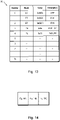
- Figure 13 shows a table 92 listing types of header, the EtherType value and a description of the corresponding protocol.
- EtherType can be particularly useful for frame type identification and using dedicated logic, for example in the form of an Ethernet block comparator 34, which consumes less area, can be useful.
- a table 97 is shown which lists different types of frames and five different types of filters, i.e., five differently configured comparator units 32, 33, 34.
- Frame types include IEEE 802.1AS network control traffic such as gPTP or SPR, Address Resolution Protocol (ADP), Link Layer Discovery Protocol (LLDP), IEEE 1722, IPv4, TCP/IPv4, UDP/IPv4, SOME/IPv4, ICMP/IPv4, IPv6, TCP/IPv6, UDP/IPv6, SOME/IPv6, ICMP/IPv6, Double tagged and Null Stream Identification for FRER (IEEE 802.1CB).
- IEEE 802.1AS network control traffic such as gPTP or SPR, Address Resolution Protocol (ADP), Link Layer Discovery Protocol (LLDP), IEEE 1722, IPv4, TCP/IPv4, UDP/IPv4, SOME/IPv4, ICMP/IPv4, IPv6, TCP/IPv6, UDP/IPv6, SOME/IPv6, ICMP/IPv6, Double tagged and Null Stream Identification for FRER (IEEE 802.1CB).
- a first filter for example, a first configurable comparator unit 32
- Input_0 can inspect protocol (PROT) and EtherType (TYPE) fields and a specific frame-type filter bit.
- PROT protocol
- TYPE EtherType
- a second filter for example, a second configurable comparator unit 32, Input_1, can inspect four bytes using a reference value and an optional mask, in either precise or expand mode.
- a third filter (for example, a third configurable comparator unit 32), Input_2, can inspect four bytes using a reference value and an optional mask, in either mask, precise or expand mode.
- a fourth filter (for example, a fourth configurable comparator unit 32), Input_3, can inspect four bytes using a reference value and an optional mask, in either precise or expand mode.
- a fifth filter (for example, a fifth configurable comparator unit 32), Input_4, can inspect two bytes using the VLAN C tag, a fixed mask of xoooF and a mask in mask mode.
- i is the index of the matching filter.
- the index number depends upon software configuration of the Filter Type. Text fields in grey italics are redundant checks.
- the matching unit 36 includes a crossbar block 37 and a cascade 38.
- the crossbar block 37 comprises M multiplexers 111 (where M is a positive, non-zero integer) each able to select one of N matches (where N is a positive, non-zero integer), i.e ., one of N outputs 35 from the comparator units 32, 33, 34, and to provide this as an input Input_0, Input_1, ..., Input_M to an AND gate 123.
- This arrangement is repeated U times (where U is a positive, non-zero integer).
- One of the inputs to the multiplexers 111 may include one or outputs 39 from one or more AND gates 123 as a reusable result 40.
- OR gates (not shown) can be used receiving, for example, outputs 35 of the comparator units 32, 33, 34 and/or one or more results 40 from the cascade 38.
- comparator pool 31, matching unit 36 and priority select unit 37 are shown in a different way.
- the crossbar block 37 (or “crossbar switch”) provides junctions 124 (or “interconnects”) between comparator units 32, 33, 34 and the AND gates 123.
- the junctions 124 are configurable via configuration registers 125.
- Each AND gate 123 1 , 123 2 ,...123 M is supplied with a respective set of crossbar outputs 126 1 , 123 2 , ..., 126 M .
- Each set of crossbar outputs 126 1 , 123 2 , ..., 126 M may comprise zero, one, two, three or more crossbar outputs which are coupled to a comparator unit output 35.
- an output 39 1 , 39 2 ,..., 39 M from one or more AND gates 123 1 , 123 2 ,...123 M can be brought back as inputs to the crossbar block 37. This can allow the number of crossbar inputs to be reduced. For example, it is possible to pre-qualify all traffic for a given UDP destination port and use the second round in crossbar to distinguish the possible sources, such as source IP and source port.
- the minimum event rate is 700 ns.
- the filter 21 Figure 3
- the priority select unit 41 comprises logic 131 and configuration registers 132.
- the priority select unit 41 can implement a strict priority scheme. For example, a simple implementation can be used which prioritises output according to the output of the cascade 38. Thus, the first output (identification number 0) has the highest priority, whereas the last output (identification number U) has the lowest priority.
- three comparator units 32, 33, 34 can be used to identify (a) IPv4 destination address, (b) IP protocol as TCP and (c) TCP destination port as 80.
- Three AND gates 123 (“cascades") can be used, namely (I) a+b+c, (II) a+b and (III) a only.
- the cascades 123 can be ordered in a way that cascade I has highest priority (#0), and cascade III has the lowest priority (e.g., #2).
- cascade I has highest priority
- cascade III has the lowest priority (e.g., #2).
- the three types of frames are sorted in the following order, namely:
- a chain translation can be used which employs a table of numbers to translate between U and an output priority V.
- Priority selection allows simple coding of hierarchical conditions, as described earlier.
- frames can be forwarded to its own DMA channel or, as per configuration in chain selection, to the DMA channel for the web server (same target as IPv4).
- Figure 17 shows configuration of the crossbar 37 for some of the frame types shown listed in table 97 ( Figure 14 ).
- the same output 35 can be used to identify different frames.
- a dedicated filter 21 i.e. , a configured filter 21 for TCP session requests is shown.
- the filter 21 is configured to catch a synchronise request (or "SYN request") sent by a client (not shown).
- the filter 21 can be set by examining:
- the destination address and the destination port are unique for flow control in a virtual machine (VM) (not shown). Once a match has been found, VM configures filtering for the connection.
- VM virtual machine
- the "always present" entry for "TCP SYN" triggers management software (not shown).
- the management software (not shown) checks if the TCP connection is OK. If yes, the management software (not shown) configures a lower prior filter for this TCP connection. When a frame with "TCP FIN” appears, this again goes to the management software (not shown), which removes the TCP connection from filter.
- a first offset counter 141 1 hides the optional 802.1Q header and a second offset counter 141 2 could be start at IPv4/IPv6 payload to hide optional IP headers.
- Distinction between fields before and after the EtherType field 10 is helpful as it can compensate for the existence of the VLAN tag 9 existence during offset calculation. Distinguishing between layer 2 and layer 3 offset can be done through dedicated configuration or by using a programmed offset value.
- an Ethernet MAC 151 typically provides the receive data in serial form, for instance in blocks of 32-bit data words (with size information if the frame size is not a multiple of 4 bytes).
- a comparator can take two approaches to filtering such data.
- a serial receive data stream for example, on chunks of data (a data word) provided by the MAC 151.
- An FSM used to identify the relevant parts in frame.
- byte offset selector is limited to positions inside the data word. This can be achieved either by shifting/splitting the value to fit to the byte position inside the frame ("filter checked sequential") or by expanding the receive data to the width of the comparator.
- comparator is expanded by B-1 byes (where B is 4 for a 32-bit MAC data bus) to simply byte offset handling. Comparator with greater than B is handled sequentially (e.g ., 64-bit comparator on 32-bit MAC data bus).
- a 32-bit configurable comparator unit 32 is shown in more detail.
- Frame data are forwarded by MAC 151 on arrival to buffer 26 via a data bus 45.
- the data bus 42 is 32-bit wide and so 8-bit data bytes 160, 161,..., 167 are grouped into 32-bit blocks 168, 169.
- a buffer 46 can store the last three bytes from a previous block 168. This can allow data to be expanded to 48 bits.
- a byte selector 47 selects which bytes of the expanded data to pass to the value comparator 44 based on an offset defined in configuration 61.
- Configuration 61 pass a reference value and an optionally mask to the value comparator 44.
- Configuration 61 also sets mode (e.g ., mask, expand, precise) which passed to the value comparator 44 and the FSMs 64, 65. Offsets are handled by offset counters 57, offset mode controller 59 and position control 60 according to configuration 61.
- position control 60 checks byte position P and byte position P+1. In other the other two modes, position control 60 only checks byte position P.
- the first output 53 of the value comparator 44 is supplied to a first, three-state FSM 64 and the second output 54 of the value comparator 44 is supplied to each of the first, three-state FSM 64 and a second, two-state FSM 65.
- the three-state FSM 64 includes first, second and third states 171, 172, 173 and a decision point 174 (or "check point").
- the FSM 64 Following a RESET, the FSM 64 enters the first state 171 (or "WAIT state”). In response to detecting a start of frame (“start"), the FSM 64 changes to the second state 172 ("CHECK 1"). Match1 is used to decide how to proceed after the check point 174.
- the first value comparator output 53 is set to '1' (i.e., there is a match) AND the mode is NOT EXPAND, then the first FSM output 66 is set to '1', otherwise it is kept as '0'.
- the FSM 64 changes to a third state 174 ("CHECK 2").
- the first FSM output 66 depends on whether the second value comparator output 54 is set to '1' or '0' and returns to the first state 171 ( i.e. , WAIT state).
- the two-state FSM 65 includes first and second states 181, 182 and a check point 183.
- the FSM 65 Following a RESET, the FSM 65 enters the first state 181 (or "WAIT state”). In response to detecting a start of frame (“start"), the FSM 65 changes to the second state 182 ("CHECK 1").
- Block comparator unit 34 ( Figure 4 ) is similar to that of a configurable comparator unit 32 except that for B reference values and thus B value comparators 44' ( Figure 8 ) and B outputs, there are B two-state FSMs 65 and B match outputs 71 to further processing 70. As block comparators 34 do not have an expand mode, only the simple two-state FSM 65 is required.
- an integrated circuit 200 in the form of a microcontroller is shown.
- the microcontroller 200 includes the CPU sub-system 211, an integrated level 2 and level 3 switch 212 and system memory 213 interconnected by a system bus 215.
- the CPU sub-system 211 includes one or more CPUs 216 (herein, for clarity, reference will be made to a CPU 216) and memory 217 storing application software 218.
- the CPU 216 loads and executes the application software 218.
- the system memory 213 is used to store data in transmit queues 219 and receive queues 220.
- the switch 212 includes layer 2 controller 231 (e.g. , media access controllers) and corresponding temporary storage 232. In some cases (for example, where the integrated layer 2 and layer 3 device is not a switch, but instead an end station) there may be only one layer 2 controller and one temporary storage 232. If there are multiple layer 2 controllers 231, then the switch 212 may include an arbitration unit 233 which feeds frames to the classification unit 23.
- the classification unit 23 is coupled to a forwarding control unit 243 which can pass received data to a transmit message handler 244 for suitable forwarding or to the bus master interface 255 for passing the received data to system memory 213.
- the forwarding control unit 243 and bus master interface 255 serve as the actioning unit 25.
- the layer 2 controller/s is (are) connected to an external physical layer transceiver (PHY) (not shown) or internal ( i.e ., on chip) PHY module (not shown).
- PHY physical layer transceiver
- the end switch 212 may have direct memory access capability and transfer data between a layer 2 controller 231 and system memory 213 without CPU intervention.
- the switch 212 includes special function register (SFR) 246.
- SFR special function register
- the switch 212 is controlled by the CPU 216 by a peripheral bus interface 247 via the SFR 246.
- a frame 22 is received by the filter 21 (step S1).
- the frame 22 is stored in receive buffer 26 (step S2) and is classified by the classification unit 23 (step S3).
- the classification unit 23 outputs a classification number 24.
- the actioning unit 25 processes the frame 22 according to the classification number 24 (step S4).
- the actioning unit 25 may, for example, drop the frame, manipulate the frame, forward it to a port or transfer the frame to an on-chip sub-system or peripheral module.
- a communications system 1000 which is deployed in a vehicle 1001, such as a motor vehicle, is shown.
- Network traffic is generally increased by the addition of ADAS electronic control units (ECUs) 1010 and new cloud services 1011.
- ECUs electronice control units
- communications module 1021 and cockpit module 1022 on which third party applications (not shown) operate should be separated from the in-vehicle network modules 1023, 1024 and filter data appropriately.
- the communications system 1000 includes a communication gateway 1031 which include a microcontroller 200 having an integrated Ethernet switch 212 providing a layer-2 ("L2”) switch and layer-3 (“L3") routing, and L2 Ethernet switches 1032, 1033.
- a communication gateway 1031 which include a microcontroller 200 having an integrated Ethernet switch 212 providing a layer-2 (“L2”) switch and layer-3 (“L3") routing, and L2 Ethernet switches 1032, 1033.
- L2 layer-2
- L3 layer-3
- the switch 212 can have plural Gigabit Ethernet ports 1041, 1042, 1043 and provide VLAN tagging/untagging, MAC/IP address filtering and TCP/UDP port filtering.
- Figure 27 illustrates a configuration whereby the switch 212 is separate in-vehicle networks using VLANs 1051, 1052, 1053.
- the integrated L2/L3 switch 212 is connected to the wireless communications module 1021 forming a first VLAN 1051.
- the integrated L2/L3 switch 212 may be connected via a first L2 Ethernet switch 1032 to the cockpit module 1022 via a second VLAN 1052.
- the switch integrated L2/L3 switch 212 may be connected via a third L2 Ethernet switch 1033 to a sensing module 1023 and a cognitive module 1024 via a third VLAN 1052.
- the integrated L2/L3 switch 212 may be connected to ADAS electronic control units (ECUs) 1010 via CAN-FD network 1060.
- ECUs ADAS electronic control units
- the filter herein described can be included in integrated circuits other than microcontrollers and systems-on-a-chip (SoCs). For example, they can be used in application-specific ICs (ASICs).
- SoCs systems-on-a-chip
- ASICs application-specific ICs
- the filter can be used in communication peripherals and be used in automotive, industrial and data centre applications.
- the communication protocols are not limited to Ethernet and CAN (FD, XL).
Abstract
Description
- The present invention relates to frame data processing, in particular to classifying frame data received from one or more communications networks, for use in frame filtering, and to a frame filtering.
- Increasingly in automotive and industrial applications, software running on a system-on-a-chip (SoC) or a microcontroller (MCU) use different, dedicated processing paths to exchange data over communications networks, such as Ethernet and controller area network (CAN) networks.
- Hardware-implemented filters can be used to check parameters in incoming data received from communication network interfaces to allow a target in the SoC or MCU (such as a CPU) to know what to do with the incoming data. For instance, in Ethernet and CAN frames, such parameters include identifiers (in particular, stream ID or CAN ID), addresses (for example, destination address), message types and higher layer protocol fields (such as IPv4).
- Hardware-implemented filters can be implemented in several, different ways.
- A memory- or register-based filter can be used to determine whether incoming data matches a filter criterion. A filter criterion may be a pattern (such as a field in a header), a masked pattern, a range or a combination thereof. The filter criterion may take the form of a value stored in memory or register(s) which may be programmed.
- A series of filters can be used to process incoming data. Thus, a first filter can be used to perform filtering based on a first criterion, then a second filter can be used to carry out filtering based on a second criterion and so on. This approach is suitable for protocols having a comparatively low event rate, such as CAN, where the interval between events is greater than 100 µs.
- Filters, however, can be arranged in parallel using (hardware) registers, Ternary Content Address Memory (TCAM) or hash tables. A parallel approach usually provides a result much faster than a sequential approach and therefore suits protocols with higher event rates, where the interval between events is less than 1 µs, and/or implementations where several data interfaces use the same pool of filters.
- Filtering is usually customised for a particular protocol and use case.
- For example, in CAN, filtering is mainly done using only media access control layer fields. In Ethernet applications, filtering can also employ only MAC layer fields, but in more sophisticated applications can use higher-level protocols, such as IP protocol.
- Use of parallel filter arrangements and deeper forms of filtering comes at a cost. For example, deeper forms of filtering increases complexity of filters in terms of the number of fields use, their variations and depth. Moreover, complex filter arrangements tend to have a large silicon footprint and consume a large amount of power.
- According to a first aspect of the present invention there is provided a circuit for use in frame filtering. The circuit comprises a plurality of comparator units. Each comparator unit is configured, in response to receiving at least a part of a data frame, to perform a determination whether data in a portion of the data frame matches respective reference data and to provide a result to a comparator unit output based on the determination. The circuit comprises a crossbar switch having crossbar inputs coupled to respective comparator unit outputs and configured to provide sets of crossbar switch outputs via configurable interconnects. The circuit comprises a set of result-combining logic units, each result-combining logic unit coupled to a respective set of crossbar switch outputs and to provide a logic unit output (or "matching output").
- The circuit can be used to help classify and, thus, filter frames with greater flexibility, which makes better use of resources, and which is easier to adapt to different applications.
- The configurable interconnects may be provided by multiplexers. At least one crossbar input may be configurably (or "re-configurably" or "selectably", for example, programmably) provided to at least two of the result-combining logic units. Thus, a result of a comparison can be used more than once. At least one result-combining logic output may be configurably provided as a crossbar input. Thus, results can be re-used. The plurality of comparator units may comprise a plurality of configurable comparator units operable in at least first and second modes which are selectable, wherein, in the first mode, the data portion is maskable with a mask. The plurality of configurable comparator units may be operable to receive two sets of reference data and to perform the determination using both sets of reference data. The two sets of data may be concatenated. At least some of the plurality of comparator units may be arranged to apply an offset so as to select the portion of the data frame to be used in the determination. At least some of the plurality of comparator units may comprise one or more finite state machines for processing a comparison of the portion of the data with reference data. The comparator units may comprise at least one block comparator unit configured to compare the portion of the data frame with B sets of reference data, where B is a positive non-zero integer which is greater than or equal to 4, for example, between 4 and 32. B may take values of 2 n where n is a positive non-zero integer (for example, B may be 4, 8, 16 and 32) for identifying up to B matches and/or 2 n -1 (for instance, B may be 3, 7, 15 or 31) for identifying up to B-1 matches and a no match. The result-combining logic units may be or include AND gates. The result-combining logic units may be or include OR gates, for instance, to identify presence of one of several matches (such as one of several IP addresses).
- The plurality of comparator units may include configurable comparator units (capable of being re-configured), pre-configured comparator units and/or block comparators units. For example, the plurality of comparator units may only include configurable comparator units. Comparator units may be configured to handle data (i.e., perform matching) in different sizes of blocks, such as 2 bytes, 3 bytes or 4 bytes. For each type of comparator unit (e.g., configurable comparator units), there may be a first set of comparator units configured to handle data of a first block size, such as 2 bytes, a second set of comparator units configured to handle data of a second, different block size, such as 3 bytes, and, further optionally, a third set of comparator units configured to handle data of a third, different block size, such as 4 bytes. There may be more configurable comparator units than pre-configured comparator and/or block comparators units.
- According to a second aspect of the present invention there is provided a classifier comprising the circuit of the first aspect and a priority select arranged to receive logic unit outputs from the circuit and to generate a classification number in dependence on the logic unit outputs.
- According to a third aspect of the present invention there is provided a filter comprising the circuit of the first aspect or the classifier of the second aspect, and an actioning unit configured to process frames in dependence on the logic unit outputs and/or the classification number.
- According to a fourth aspect of the present invention there is provided an integrated circuit comprising the classifier of the second aspect or the filter of the third aspect. The integrated circuit is a microcontroller, a system on a chip or an application specific integrated circuit.
- According to a fifth aspect of the present invention there is provided a switch or an end station comprising the classifier of the second aspect or the filter of the third aspect.
- According to a sixth aspect of the present invention there is provided a system comprising a communication gateway comprising the integrated circuit of the fifth aspect, at least one node (such as a module, electronic control unit or other computing node) in communication with the integrated circuit and the filter is arranged to receive frames from the at least one node and to process the frames according to the classification number. A node may be a powertrain module (such as, an engine electronic control unit), a chassis module (such as, a brake-by-wire electronic control unit), a body/comfort module (such as a climate control electronic control unit), a driver assistance module (such as lane-departure control unit), an infotainment module or the like. The integrated circuit may provide a switch or may provide an end station in a communication system.
- According to a seventh aspect of the present invention there is provided a vehicle comprising the system of the sixth aspect which is functionally-integrated into the vehicle. The system may be used to provide communication between computing nodes within the vehicle and/or between a node in the vehicle and a node outside the vehicle (e.g., another vehicle or a node via an external communications network) The vehicle may be motor vehicle. The motor vehicle may be a motorcycle, an automobile (sometimes referred to as a "car"), a minibus, a bus, a truck or lorry. The motor vehicle may be powered by an internal combustion engine, one or more electric motors or both (i.e., "hybrid"). The vehicle may be an aircraft (or other airborne vehicle), a train, a ship (or other watercraft) or spacecraft.
- According to an eighth aspect of the present invention there is provided a method comprising receiving at least a part of a data frame, for plural sets of reference data, performing a determination whether data in a portion of the at least part of the data frame matches reference data and to provide a result based on the determination, selecting groups of results and processing a group results using a result-combining logic unit to obtain a logic unit output.
- The method may further comprise generating a classification number in dependence on the logic unit outputs. The method may further comprise processing frames in dependence on the logic unit outputs and/or the classification number.
- Certain embodiments of the present invention will now be described, by way of example, with reference to the accompanying drawings, in which:
-
Figure 1 illustrates anIEEE 1722 frame; -
Figure 2 illustrates data flow in AVB filtering; -
Figure 3 shows plots of configuration flops as a function of number of filters for a first, - simpler filtering process and a second, more complex filtering process;
-
Figure 4 illustrates data flow in a frame filter in accordance with the present invention; -
Figure 5 is a schematic block diagram of a configurable comparator unit which includes a value comparator and at least one finite state machine (FSM); -
Figure 6 is a schematic circuit diagram of a configurable comparator unit; -
Figure 7 shows three modes of operating a configurable comparator unit; -
Figure 8 illustrates a block comparator; -
Figure 9 shows three modes of operating a filter in more detail; -
Figure 10 illustrates an untagged Ethernet frame, a single-tagged Ethernet data frame and a double-tagged Ethernet data frame; -
Figure 11 illustrates an IPv4 header; -
Figure 12 illustrates an IPv6 header; -
Figure 13 is a table which illustrates different modes of filtering based on EtherType; -
Figures 14 is table illustrating different filter fields; -
Figure 15 is a block diagram of an identification stage including a crossbar and cascade; -
Figure 16 is a schematic block diagram of a classification unit; -
Figure 17 is a block diagram of an example of crossbar and cascade; -
Figure 18 illustrates a dedicated filter for TCP session requests; -
Figure 19 illustrates filter offsets for three different types of frames; -
Figure 20 illustrates different offsets for selecting orhiding layer 2 and/orlayer 3 headers; -
Figure 21 is a schematic block diagram of a configurable comparator unit which includes a value comparator and at first and second FSMs; -
Figure 22 illustrates use of a store in the configurable comparator unit shown inFigure 21 ; -
Figure 23 is state diagram of the first FSM shown inFigure 21 ; -
Figure 24 is a state diagram of the second FSM shown inFigure 21 ; -
Figure 25 is a block diagram of a microcontroller; -
Figure 26 is a process flow diagram of frame filtering; and -
Figure 27 schematically illustrates a motor vehicle which includes an integrated circuit which includes a frame filter. - Referring to
Figures 1 and 2 , anIEEE 1722frame 1 and afilter arrangement 11 for filtering frames received by a message handler in an Audio Video Bridging (AVB) end station are shown. - The
IEEE 1722frame 1 includes apreamble 2, a start of frame (SFD) 3, anEthernet header 4, apayload 5 and a frame check sequence (FCS) 6. TheIEEE 1722frame header 4 consists of adestination address 7, asource address 8, aVLAN tag 9 andEthernet Type 10. -
Filters 12 includes a frame-type identification block 13 which can inspect the destination address, VLAN tag and EtherType fields of a frame to determine whether aframe 14 received from the media access controller (MAC) (not shown) is anIEEE 1722frame 1 and whether it is compliant with IEEE 802.1AS. Thefilters 12 can include up to 16other filters 15 for identifying, for instance, frames with given MAC addresses. Once frames have been identified, achain selection block 16 selects a corresponding chain. Achain identifier 17 and theframe 1 are passed to a direct memory access controller (DMAC) 18 for storing in the appropriate queue in system memory (not shown). - Different applications (i.e., different use cases) may require different filters and follow different approaches to classification. For example, in one application, a user may want to filter frames based on MAC address, VLAN and some (OSI)
level 4 data, while in another, different application, a user may want to filter frames based on IP address and port numbers. - The
AVB filter 11 hereinbefore described can only be used for filtering 1722 AVB frames, and is based on stream ID. If different filtering is required, for example, based on IPv4 or IPv6 addresses or deep-package inspection, then different filters are needed. - One way in which this can be achieved is to provide a full set of filters which cover a full range of applications from which users can choose filters of interest. This, however, increases the size of the silicon footprint needed for filters as well as the number of bits used for configuring the filters.
- Referring to
Figure 3 , for a relativelysimple AVB filter 11, as the number of filters increase, the number of configuration flops increases. For a more complex filter, the number of configuration flops increases significantly with the number of filters. - Referring to
Figure 4 , a filter arrangement 21 (herein also referred to simply as "filter") is shown which is flexible and configurable according to application. - The
filter 21 can provide and/or enable flexible frame identification, flexible filter offset, multiple filter positions, flexible DMA chain mapping and/or filter results to be re-used. - Instead of using hard-coded identification, the
filter 21 is configurable. Thefilter 21 can check one or more selectable parts of a receivedframe 22. Thefilter 21 can perform identification distributed across an OSI-layer header (e.g., for UDP, Ethernet Type, IPv4 Address, UDP Protocol type, UDP port, and application-specific IDs in UDP payload) and multiple positions within a frame. In cases where frame identification is based only on, for example, UDP port number, filter results can be re-used and so fewer hardware resource are needed. - Referring to
Figure 4 , thefilter 21 comprises aclassification unit 23 for identifying whether a part (or parts) of aframe 22 matches a pre-defined criterion (or corresponding criteria) and outputting aresult 24 in the form aclassification number 24. Theclassification number 24 is passed to anactioning unit 25 which determines how theframe 22 should be processed based on theclassification number 24. - While classification is performed, the
frame 23 can be stored inmemory 26, such as a first-in, first-out (FIFO) buffer. - The
classification unit 23 includes a pool 31 (or "set" or "bank") of comparators. Thecomparator pool 31 can include a set ofconfigurable comparator units 32, a set ofpre-configured comparator units 33 and/or a set ofblock comparators units 34. - The
comparator pool 31 may only include only one type of comparator unit, such asconfigurable comparator units 32. - The
comparator pool 31 may includecomparator units comparator pool 31 may include sixty-four 2-byteconfigurable comparator units 32, sixty-four 3-byteconfigurable comparator units 32 and sixty-four 4-byteconfigurable comparator units 32. There may be, however, fewer ormore comparator units 32 of each size. - The
comparator pool 31 may includeconfigurable comparator units 32,pre-configured comparator units 33 and a set ofblock comparators units 34. For example, there may be sixty-fourconfigurable comparator units 32 for each filter size, , two pre-configured comparator units 33 (optionally, two for each filter size) and one or two block comparators units 34 (optionally, one or two for each filter size). - As will be explained in more detail later, a
pre-configured comparator units 33 and ablock comparators unit 34 are generally simpler versions of theconfigurable comparator unit 32, i.e., generally containing less hardware logic, but the hardware logic is optimised for particular situations. For example,pre-configured comparator units 33 are intended to be employed for filtering commonly-used fields, such as EtherType.Block comparators units 34 are intended for filtering a limited number of fields (for example, only one field) which can have many values (such as up to 16 values), for instance, for use in AVB. - Referring still to
Figure 4 , theclassification unit 23 includes amatching unit 36 forprocessing outputs 35 of thecomparator units unit 36 includes a crossbar unit 37 (herein also referred to as a "crossbar block", "crossbar switch" or simply "crossbar") and a cascade unit 38 (herein also referred to as a "cascade block" or simply "cascade"). As will be explained in more detail later, thecrossbar 37 andcascade 38 are programmable and can be used to identify specific combinations of data. Furthermore, at least some ofresults 40 from thecascade 38 can be re-used by thecrossbar 37. - The
classification unit 23 includes a priority select block 41 (or "priority select unit") which processes theresults 39 from the matchingunit 36 and outputs theclassification number 24. - The
classification unit 23 includes aninterface 42 to ahost 43. Thehost 43 can program configuration registers 62 (Figure 5 ) which are used to configure thecomparator units Figure 16 ) which are used to configure thecrossbar 37 andcascade 38, and configuration registers 132 (Figure 16 ) which are used to configure the priorityselect block 41. - Referring to
Figure 5 ,comparator units value comparator 44.Incoming frames 22 are received from adata bus 45 via adata store 46 andbyte selector 47 which, based on an offset 48, selectsdata 49 for comparison using first andsecond values mode 52 and outputs first andsecond outputs Match 1" and "Match 2"). - A
comparator unit position control unit 57 which comprises an offsetcounter 58, offsetmode 59 andposition control 60. Offsets are described in more detail hereinafter. - A
comparator unit configuration unit 61 which includes a set of configuration registers 62 andconfiguration logic 63 for configuring thevalue comparator 44, thebyte selector 54 and the offset andposition control unit 57. - A
comparator unit outputs value comparator 44. - The
outputs FSMs output value comparator 44 are output tocircuitry 70 for further processing. Thecircuitry 70 includes thematching unit 36 and the priorityselect unit 41. - Referring to
Figure 6 , avalue comparator 44 receives n bits ofdata 49 from the frame 22 (Figure 5 ) on a first line 71 ("data line"), amode 52 on a second line 72 ("mode line"), a first n-bit value 50 on a first line 73 ("first value line") and a second n-bit value 51 on a second line 71 ("second value line"). - As will be explained hereinafter in more detail, the
first value 50 can serve as a mask or a filter value ("a first filter value" or "first reference"), and thesecond value 51 can serve a filter value ("a second filter value" or "second reference"). - The
mode 52 and thefirst value 50 are fed, via themode line 72 and thefirst value line 73, as inputs to a bitwise OR gate 75 (in the form of n 2-input OR gates). The n-bit wide output of the bitwise OR gate is passed, vialine 76, to a bitwise AND gate 77 (in the form of n 2-input AND gates) which also receivesdata 49 via thedata line 71. - The output of the bitwise AND
gate 77 is passed, vialine 78, as one of the inputs to a first bitwise XOR gate 79 (in the form of n 2-input XOR gates) which also receives, as its other input, thesecond value 51 received on thesecond value line 74. The n-bit wide output of the firstbitwise XOR gate 79 is output vialine 80 to a first n-input ANDgate 81. The single-bit output of the first n-input ANDgate 81 is output as a firstvalue comparator output 53 vialine 82. -
Data 49 and thefirst value 50 are fed as inputs to a second bitwise XOR gate 83 (again in the form of N 2-input XOR gates). The n-bit wide output of the secondbitwise XOR gate 83 is output vialine 84 to second n-input ANDgate 85. The single-bit output of the second n-input ANDgate 85 is output as a secondvalue comparator output 54 vialine 86. Thebitwise XOR gates - As mentioned earlier, the
comparator units - Referring also to
Figure 7 , in a so-called "mask mode", thefirst value 50 is used as a mask and thesecond value 51 serves as the value to be matched ("reference"). Themask 50 is used to mask individual bits so that thecomparator 79 only compares unmasked bits of theinput data 49 and thereference 51. - In a so-called "expand mode", the first and second filter values 50, 51 can be concatenated to create a double-width filter, i.e., 2n bits wide. Alternatively, in a so-called "precise mode", each of the first and second filter values 50, 51 are each used as an n-bit reference. Herein, modes are handled in part by the
value comparator 44 and in part by theFSMs value comparator 44 using multiplexers (not shown). - A
pre-configured comparator unit 33 is similar to aconfigurable comparator unit 32. It may differ, however, in that some of thevalues values pre-configured comparator units 33 may be identical to theconfigurable comparator units 32 except that re-programming of values is disabled. - Referring to
Figure 8 , ablock comparator 34 may comprise a set of B simplified value comparators 44', where B is a positive, non-zero integer, for example between 8 and 16. Each simplified value comparators 44' comprises abitwise XOR gate 79 and an ANDgate 81. The same n-bit data is supplied to each of the B simplified value comparators 44' and each simplified value comparators 44' compares the data with a respective n-bit value, namely value [0], value [1], ...., value [B-1]. In some cases, one or more of the values may be fixed and not configurable. The arrangement can be useful for routing applications. -
Block comparator units 34, while less flexible, are simpler and thus cheaper to implement. Using filter modes (for example, mask, precise and expand modes) can help reduce the amount of processing power ("flops") needed to configure fully the classification unit 24 (Figure 4 ). Using block comparator units 34 (for example, 16 values on 1 offset/mask) can help reduce the area ofclassification unit 23. Also, using comparator units 34 (for example, groups of four filters) which share the same offset can also help to reduce the area consumed by the offset selectors. -
Figure 9 illustrates processing of stream ofdata 87 in a frame 22 (Figure 5 ) which starts frombyte 0 and includes bytes N, N+1,..., N+5 by aconfigurable comparator unit 32 having a width of 3-bytes. - Referring to
Figures 7 and9 , an offset 88 is used to select thestart 89 of thedata 87 to be processed, which in this case is byte N. - In mask mode, three bytes of data N, N+1 and N+2 are masked using stored mask provided by the
first value 50 and compared with reference data provided by thesecond value 51 by thefirst comparator 79. - In expand mode, six bytes of data N, N+1, N+2, N+3, N+4, N+5 are left unmasked and compared with concatenated data provided by first and
second values second comparators - In precise mode, the first three bytes of data N, N+1, N+2 are left unmasked and compared with data provided by a
first value 50 by thefirst comparator 79. The second three bytes of data N+3, N+4, N+5 are also left unmasked and compared with asecond value 51 by thesecond comparator 83. - Further details of the
value comparator 44 and how the mode is set will be described in more detail hereinafter. - The
classification unit 23 is able to check an individual part or individual parts of a frame by using an offset or offsets. The relevant parts of the frame vary between protocols and it may be desirable to use different protocols in parallel and, thus, check different parts of the frame in parallel. - Before explaining how offsets are used, some examples of different communication protocols and example of which parts of a frame may be of interest will described.
- Referring to
Figure 10 , first, second and third Ethernet frames 11, 12, 13 are shown. - The
first Ethernet frame 11 is an untagged Ethernet frame having an IEEE 802.3 frame structure in which the 16-bit EtherType field 10 follows directly after theSource MAC address 8. TheEtherType field 10 is used to indicate which protocol is encapsulated in the payload of the frame. For IPv4, EtherType = 0x0800 and, for IPv6, EtherType = 0x86DD. - The second and third Ethernet frames 12, 13 support virtual LANs (VLANs) and conform to IEEE 802.1Q. In the
second Ethernet frame 12, a 32-bit VLAN header is added immediately after thesource MAC address 8 thereby shifting theEtherType field 10 by 4 bytes. In thethird Ethernet frame 13, two VLAN headers are added (referred to as "double-tagging"). A 32-bit service tag (S-VLAN tag) is added immediately after thesource MAC address 8 followed by a 32-bit customer tag (C-VLAN tag) thereby shifting theEtherType field 10 by 8 bytes. - An Ethernet frame can be used to transmit data as User Datagram Protocol (UDP) datagrams or in Transmission Control Protocol (TCP) segments transferred via Internet Protocol version 4 (IPv4) or Internet Protocol version 6 (IPv6).
- Referring to
Figures 11 and 12 , anIPv4 header 90 and anIPv6 header 91 are shown. - Referring in particular to
Figure 11 , the IPv4 header consists of 20 bytes and has 12 fields including Version (i.e., b0100), IP Header length (IHL), Type of Service, Total Length (i.e., the size of the datagram including the header and payload), Identification, Flags, Fragment Offset, Time to Love (TTL), Protocol (e.g., 6 indicates TCP and 17 indicates UDP), Header Checksum, Source Address (i.e., the IP address of the sending node) and Destination Address (i.e., the IP address of the intended receiving node). - Referring in particular to
Figure 12 , the IPv6 header consists of 40 bytes and has eight fields including Version (i.e., b0110), Traffic Class, Flow Label, Payload Length, Next Header which species the type of header (and uses the same scheme used in the Protocol field in IPv4), Hop Limit (which replaces the TTL field in IPv4), Source Address (i.e., the IP address of the sending node) and Destination Address (i.e., the IP address of the intended receiving node). - The
classification unit 23 can be adjustably configured to check multiple fields to identify EtherType (i.e., IPv4 or IPv6) and Protocol or Next Header (i.e., UDP or TCP). - Variability in the position of the EtherType field can be accommodated by using a dynamic offset which can set according to whether an IEEE 802.1Q header is used or not used.
- EtherType can be analysed by a 2-byte
configurable comparator unit 32. This could be achieved, for example, using twocomparator units 32 operating in precise mode. This, however, can be considered to be an unnecessary overhead since offset may not be needed, offset multiplexing can be computationally expensive and logic for different modes is not required. Thus, ablock comparator unit 34 for inspecting the EtherType field and, optionally, Protocol/Next Header fields can be used. Herein, such asblock comparator unit 34 is referred to as an "Ethernetblock comparator unit 34". In addition to checking EtherType, the Ethernetblock comparator unit 34 can also check the Protocol field and/or the Next Header field. - As explained earlier, reference values in a comparator unit may be configurable, i.e., values stored in registers may be configurable, or fixed. Given that the pool of potential values for EtherType and Protocol field and/or the Next Header field is small, then at least some of the values in the Ethernet
block comparator units 34 can be fixed. - Referring to
Figure 13 , theEthernet comparator unit 34 includes registers 62 (Figure 5 ) which may store values of EtherType, for example, 0x0806 for Address Resolution Protocol (ARP), 0x0800 for IPv4, 0x08DD for IPv4, and values of Protocol and Next Header, for instance 0x06 for TCP and 0x11 for UDP.Figure 13 shows a table 92 listing types of header, the EtherType value and a description of the corresponding protocol. - For Ethernet protocols, the number of fields (and, thus, offset values) is limited and so the classification keys tend to be limited, focussing mainly on, for example, 1722 Stream ID, IPv4 address and MAC address. Accordingly, EtherType can be particularly useful for frame type identification and using dedicated logic, for example in the form of an
Ethernet block comparator 34, which consumes less area, can be useful. - Referring to
Figure 14 , a table 97 is shown which lists different types of frames and five different types of filters, i.e., five differently configuredcomparator units - Frame types include IEEE 802.1AS network control traffic such as gPTP or SPR, Address Resolution Protocol (ADP), Link Layer Discovery Protocol (LLDP),
IEEE 1722, IPv4, TCP/IPv4, UDP/IPv4, SOME/IPv4, ICMP/IPv4, IPv6, TCP/IPv6, UDP/IPv6, SOME/IPv6, ICMP/IPv6, Double tagged and Null Stream Identification for FRER (IEEE 802.1CB). - A first filter (for example, a first configurable comparator unit 32), Input_0, can inspect protocol (PROT) and EtherType (TYPE) fields and a specific frame-type filter bit.
- A second filter (for example, a second configurable comparator unit 32), Input_1, can inspect four bytes using a reference value and an optional mask, in either precise or expand mode.
- A third filter (for example, a third configurable comparator unit 32), Input_2, can inspect four bytes using a reference value and an optional mask, in either mask, precise or expand mode.
- A fourth filter (for example, a fourth configurable comparator unit 32), Input_3, can inspect four bytes using a reference value and an optional mask, in either precise or expand mode.
- A fifth filter (for example, a fifth configurable comparator unit 32), Input_4, can inspect two bytes using the VLAN C tag, a fixed mask of xoooF and a mask in mask mode.
- In
Figure 14 , i is the index of the matching filter. The index number depends upon software configuration of the Filter Type. Text fields in grey italics are redundant checks. - For example, for TCP/IPv4:
- Input_0: PROT = 1, TYPE = 0xXX06 and specific frame-type filter bit is i;
- Input_1: Reference values is IPv4 Address, Mask is No, and Mode is Precise;
- Input_2: Reference value is Port, Mask is No, and Mode is Precise;
- Input_3: Not used
- Input_4: Reference value is VLAN C tag, Mask is oxoooF, and Mode is Mask;
- For example, for TCP/IPv6:
- Input_0: PROT = 2, TYPE = 0xXX06 and specific frame-type filter bit is i;
- Input_1: Reference values is IPv6 Address, Mask is IPv6 Address, and Mode is Expand;
- Input_2: Reference value is Port, Mask is No, and Mode is Precise;
- Input_3: Reference values is IPv6 Address, Mask is IPv6 Address, and Mode is Expand;
- Input_4: Reference value is VLAN C tag, Mask is xoooF, and Mode is Mask;
- Thus, in relation to TCP/IPv4 and TCP/IPv6, depending upon whether a node is server or client, either Destination or Source IP address and port values is used.
- Referring again to
Figure 4 , the matchingunit 36 includes acrossbar block 37 and acascade 38. - Referring also to
Figure 15 , thecrossbar block 37 comprises M multiplexers 111 (where M is a positive, non-zero integer) each able to select one of N matches (where N is a positive, non-zero integer), i.e., one of N outputs 35 from thecomparator units gate 123. This arrangement is repeated U times (where U is a positive, non-zero integer). One of the inputs to themultiplexers 111 may include one or outputs 39 from one or more ANDgates 123 as areusable result 40. Additionally or alternatively, OR gates (not shown) can be used receiving, for example, outputs 35 of thecomparator units more results 40 from thecascade 38. - Referring also to
Figure 16 , thecomparator pool 31, matchingunit 36 and priorityselect unit 37 are shown in a different way. - As shown in
Figure 16 , the crossbar block 37 (or "crossbar switch") provides junctions 124 (or "interconnects") betweencomparator units gates 123. Thejunctions 124 are configurable via configuration registers 125. - Each AND
gate crossbar outputs 1261, 1232, ..., 126 M . Each set ofcrossbar outputs 1261, 1232, ..., 126 M may comprise zero, one, two, three or more crossbar outputs which are coupled to acomparator unit output 35. - Although not shown in
Figure 16 for clarity, anoutput gates crossbar block 37. This can allow the number of crossbar inputs to be reduced. For example, it is possible to pre-qualify all traffic for a given UDP destination port and use the second round in crossbar to distinguish the possible sources, such as source IP and source port. - For a 1-Gbps link, the minimum event rate is 700 ns. When running the filter 21 (
Figure 3 ) at 100 MHz, there are about 70 clock cycles which can be used to pipeline complete filtering. - Referring still to
Figure 16 , the priorityselect unit 41 compriseslogic 131 and configuration registers 132. - The priority
select unit 41 can implement a strict priority scheme. For example, a simple implementation can be used which prioritises output according to the output of thecascade 38. Thus, the first output (identification number 0) has the highest priority, whereas the last output (identification number U) has the lowest priority. - For example, three
comparator units - In the priority
select unit 41, thecascades 123 can be ordered in a way that cascade I has highest priority (#0), and cascade III has the lowest priority (e.g., #2). Thus, according to hierarchical sorting, the three types of frames are sorted in the following order, namely: - frames for TCP port 80 (which are priority #0) using classification number I and might be forwarded, for instance, to a DMA channel (not shown) for a web server (not shown);
- remaining TCP frames (which are priority #1) using classification number II and might be forwarded, for instance to a DMA channel (not shown) for the TCP stack (not shown); and
- all other IPv4 frames (which are priority #2) using classification number III and might be forwarded, for instance, to a DMA channel (not shown) for the standard IP stack (not shown).
- A chain translation can be used which employs a table of numbers to translate between U and an output priority V.
- Priority selection allows simple coding of hierarchical conditions, as described earlier. In the case of IPv6 traffic, based on classification number, frames can be forwarded to its own DMA channel or, as per configuration in chain selection, to the DMA channel for the web server (same target as IPv4).
-
Figure 17 shows configuration of thecrossbar 37 for some of the frame types shown listed in table 97 (Figure 14 ). - Referring to
Figures 14 and17 , thesame output 35 can be used to identify different frames. - Referring to
Figure 18 , an example of a dedicated filter 21 (i.e., a configured filter 21) for TCP session requests is shown. In this example, thefilter 21 is configured to catch a synchronise request (or "SYN request") sent by a client (not shown). - The
filter 21 can be set by examining: - EtherType field with a 2-byte filter using 0x08DD as a reference;
- Next header and hop limit fields with a 2-byte filter using 0x1100 as a reference and oxFFoo as a mask;
- Destination address with two 4-byte filters in expand mode;
- Destination port with a 2-byte filter using 0x8080 as a reference; and
- Offset and control fields with a 2-byte filter using 0x0200 as a reference and 0x0200 as a mask.
- The destination address and the destination port are unique for flow control in a virtual machine (VM) (not shown). Once a match has been found, VM configures filtering for the connection.
- In this example, the "always present" entry for "TCP SYN" triggers management software (not shown). The management software (not shown) checks if the TCP connection is OK. If yes, the management software (not shown) configures a lower prior filter for this TCP connection. When a frame with "TCP FIN" appears, this again goes to the management software (not shown), which removes the TCP connection from filter.
- Referring to
Figure 19 , using different offset references 1410, 1411, 1412, filter programming can be simplified for the use case. For example, a first offset counter 1411 hides the optional 802.1Q header and a second offset counter 1412 could be start at IPv4/IPv6 payload to hide optional IP headers. - Referring to
Figure 20 , untagged, single-tagged and double-tagged Ethernet frames 11, 12, 13 are again shown. - Distinction between fields before and after the
EtherType field 10 is helpful as it can compensate for the existence of theVLAN tag 9 existence during offset calculation. Distinguishing betweenlayer 2 andlayer 3 offset can be done through dedicated configuration or by using a programmed offset value. - Referring to
Figure 21 , anEthernet MAC 151 typically provides the receive data in serial form, for instance in blocks of 32-bit data words (with size information if the frame size is not a multiple of 4 bytes). - A comparator can take two approaches to filtering such data.
- In a parallel approach, all data that is potentially needed for the comparator is provided in parallel. This approach needs sufficiently large storage, such as 1024 flops for a 128-byte offset area. This approach uses byte offset selector logic using N-
times 128 to one multiplexer for a N-bit comparator as each byte offset is valid. - In a sequential approach, data is compared on a serial receive data stream, for example, on chunks of data (a data word) provided by the
MAC 151. An FSM used to identify the relevant parts in frame. In this approach, byte offset selector is limited to positions inside the data word. This can be achieved either by shifting/splitting the value to fit to the byte position inside the frame ("filter checked sequential") or by expanding the receive data to the width of the comparator. - Referring also to
Figure 22 , byte extraction using a mixture of the two approaches is used. The comparator is expanded by B-1 byes (where B is 4 for a 32-bit MAC data bus) to simply byte offset handling. Comparator with greater than B is handled sequentially (e.g., 64-bit comparator on 32-bit MAC data bus). - Referring to
Figure 21 , a 32-bitconfigurable comparator unit 32 is shown in more detail. - Frame data are forwarded by
MAC 151 on arrival to buffer 26 via adata bus 45. - Referring also to
Figure 22 , thedata bus 42 is 32-bit wide and so 8-bit data bytes bit blocks adjacent blocks buffer 46 can store the last three bytes from aprevious block 168. This can allow data to be expanded to 48 bits. - Referring again to
Figure 21 , abyte selector 47 selects which bytes of the expanded data to pass to thevalue comparator 44 based on an offset defined inconfiguration 61.Configuration 61 pass a reference value and an optionally mask to thevalue comparator 44.Configuration 61 also sets mode (e.g., mask, expand, precise) which passed to thevalue comparator 44 and theFSMs counters 57, offsetmode controller 59 andposition control 60 according toconfiguration 61. - In expand mode,
position control 60 checks byte position P and byte position P+1. In other the other two modes,position control 60 only checks byte position P. - As explained hereinbefore, a
value comparator 44 receives N-bytes data 49 and performs a comparison using two N-byte values (for instance, where N = 2). - The
first output 53 of thevalue comparator 44 is supplied to a first, three-state FSM 64 and thesecond output 54 of thevalue comparator 44 is supplied to each of the first, three-state FSM 64 and a second, two-state FSM 65. - Referring to
Figure 23 , the three-state FSM 64 includes first, second andthird states - Following a RESET, the
FSM 64 enters the first state 171 (or "WAIT state"). In response to detecting a start of frame ("start"), theFSM 64 changes to the second state 172 ("CHECK 1"). Match1 is used to decide how to proceed after thecheck point 174. - At the checkpoint, if the first
value comparator output 53 is set to '1' (i.e., there is a match) AND the mode is NOT EXPAND, then thefirst FSM output 66 is set to '1', otherwise it is kept as '0'. - At the checkpoint, if the
first output 53 is set to '1' (i.e., there is a match) AND the mode is EXPAND, then theFSM 64 changes to a third state 174 ("CHECK 2"). When the next N bytes are received, another check is performed on match2 and thefirst FSM output 66 depends on whether the secondvalue comparator output 54 is set to '1' or '0' and returns to the first state 171 (i.e., WAIT state). - Referring to
Figure 24 , the two-state FSM 65 includes first andsecond states check point 183. - Following a RESET, the
FSM 65 enters the first state 181 (or "WAIT state"). In response to detecting a start of frame ("start"), theFSM 65 changes to the second state 182 ("CHECK 1"). - At the checkpoint, if the second
value comparator output 54 is set to '1' (i.e., there is a match), then thesecond FSM output 67 is set to '1', otherwise it is kept as '0'. - Implementation of a block comparator unit 34 (
Figure 4 ) is similar to that of aconfigurable comparator unit 32 except that for B reference values and thus B value comparators 44' (Figure 8 ) and B outputs, there are B two-state FSMs 65 and B match outputs 71 tofurther processing 70. Asblock comparators 34 do not have an expand mode, only the simple two-state FSM 65 is required. - Referring to
Figure 25 , anintegrated circuit 200 in the form of a microcontroller is shown. - The
microcontroller 200 includes theCPU sub-system 211, anintegrated level 2 andlevel 3switch 212 andsystem memory 213 interconnected by asystem bus 215. TheCPU sub-system 211 includes one or more CPUs 216 (herein, for clarity, reference will be made to a CPU 216) andmemory 217storing application software 218. TheCPU 216 loads and executes theapplication software 218. Thesystem memory 213 is used to store data in transmitqueues 219 and receivequeues 220. - Referring still to
Figure 25 , theswitch 212 includeslayer 2 controller 231 (e.g., media access controllers) and correspondingtemporary storage 232. In some cases (for example, where theintegrated layer 2 andlayer 3 device is not a switch, but instead an end station) there may be only onelayer 2 controller and onetemporary storage 232. If there aremultiple layer 2controllers 231, then theswitch 212 may include anarbitration unit 233 which feeds frames to theclassification unit 23. Theclassification unit 23 is coupled to aforwarding control unit 243 which can pass received data to a transmitmessage handler 244 for suitable forwarding or to thebus master interface 255 for passing the received data tosystem memory 213. The forwardingcontrol unit 243 andbus master interface 255 serve as the actioningunit 25. - The
layer 2 controller/s is (are) connected to an external physical layer transceiver (PHY) (not shown) or internal (i.e., on chip) PHY module (not shown). Theend switch 212 may have direct memory access capability and transfer data between alayer 2controller 231 andsystem memory 213 without CPU intervention. - The
switch 212 includes special function register (SFR) 246. Theswitch 212 is controlled by theCPU 216 by aperipheral bus interface 247 via theSFR 246. - Referring to
Figures 4 and26 , operation of thefilter 21 will now be described. - A
frame 22 is received by the filter 21 (step S1). Theframe 22 is stored in receive buffer 26 (step S2) and is classified by the classification unit 23 (step S3). Theclassification unit 23 outputs aclassification number 24. The actioningunit 25 processes theframe 22 according to the classification number 24 (step S4). The actioningunit 25 may, for example, drop the frame, manipulate the frame, forward it to a port or transfer the frame to an on-chip sub-system or peripheral module. - Referring to
Figure 27 , acommunications system 1000 which is deployed in avehicle 1001, such as a motor vehicle, is shown. - Network traffic is generally increased by the addition of ADAS electronic control units (ECUs) 1010 and
new cloud services 1011. Thus, to help prevent unauthorized access,communications module 1021 andcockpit module 1022 on which third party applications (not shown) operate should be separated from the in-vehicle network modules - The
communications system 1000 includes acommunication gateway 1031 which include amicrocontroller 200 having anintegrated Ethernet switch 212 providing a layer-2 ("L2") switch and layer-3 ("L3") routing, and L2 Ethernet switches 1032, 1033. - The
switch 212 can have pluralGigabit Ethernet ports -
Figure 27 illustrates a configuration whereby theswitch 212 is separate in-vehiclenetworks using VLANs - The integrated L2/
L3 switch 212 is connected to thewireless communications module 1021 forming afirst VLAN 1051. The integrated L2/L3 switch 212 may be connected via a firstL2 Ethernet switch 1032 to thecockpit module 1022 via asecond VLAN 1052. The switch integrated L2/L3 switch 212 may be connected via a thirdL2 Ethernet switch 1033 to asensing module 1023 and acognitive module 1024 via athird VLAN 1052. Meanwhile, the integrated L2/L3 switch 212 may be connected to ADAS electronic control units (ECUs) 1010 via CAN-FD network 1060. - It will be appreciated that various modifications may be made to the embodiments hereinbefore described. Such modifications may involve equivalent and other features which are already known in the design, manufacture and use of communications network controller module and component parts thereof and which may be used instead of or in addition to features already described herein. Features of one embodiment may be replaced or supplemented by features of another embodiment.
- The filter herein described can be included in integrated circuits other than microcontrollers and systems-on-a-chip (SoCs). For example, they can be used in application-specific ICs (ASICs).
- The filter can be used in communication peripherals and be used in automotive, industrial and data centre applications. The communication protocols are not limited to Ethernet and CAN (FD, XL).
- Although claims have been formulated in this application to particular combinations of features, it should be understood that the scope of the disclosure of the present invention also includes any novel features or any novel combination of features disclosed herein either explicitly or implicitly or any generalization thereof, whether or not it relates to the same invention as presently claimed in any claim and whether or not it mitigates any or all of the same technical problems as does the present invention. The applicants hereby give notice that new claims may be formulated to such features and/or combinations of such features during the prosecution of the present application or of any further application derived therefrom.
Claims (15)
- A circuit (23), comprising:a plurality of comparator units (32, 33, 34), each comparator unit configured, in response to receiving at least a part of a data frame (22), to perform a determination whether data in a portion (49) of the data frame matches respective reference data (51; 50, 51) and to provide a result to a comparator unit output (35) based on the determination;a crossbar switch (37) having crossbar inputs coupled to respective comparator unit outputs and configured to provide sets of crossbar switch outputs via configurable interconnects; anda set of result-combining logic units (123), each result-combining logic unit coupled to a respective set of crossbar switch outputs and configured to provide a respective logic unit output (39).
- The circuit of claim 1, wherein at least one crossbar input is configurably provided to at least two of the result-combining logic units (123).
- The circuit of claim 1 or 2, wherein at least one result-combining logic output (39) is configurably provided as a crossbar input.
- The circuit of any one of claims 1 to 3, wherein the plurality of comparator units comprises a plurality of configurable comparator units operable in at least first and second modes which are selectable, wherein, in the first mode, the data portion (49) is maskable with a mask (50).
- The circuit of claim 4, wherein the plurality of configurable comparator units are operable to receive two sets of reference data (50, 51) and to perform the determination using both sets of reference data.
- The circuit of claim 5, wherein the two sets of data are concatenated.
- The circuit of any one of claims 1 to 6, wherein at least some of the plurality of comparator units (32, 33, 34) are arranged to apply an offset (48) so as to select the portion (49) of the data frame to be used in the determination.
- The circuit of any one of claims 1 to 7, wherein at least some of the plurality of comparator units (32, 33, 34) comprise one or more finite state machines (64, 65) for processing a comparison (53, 54) of the portion (49) of the data with reference data (50, 51).
- The circuit of any one of claims 1 to 8, wherein the comparator units (32, 33, 34) comprise at least one block comparator unit (34) configured to compare the portion (49) of the data frame with B sets of reference data, where B is a positive non-zero integer which is at least 4.
- The circuit of any one of claims 1 to 9, wherein the result-combining logic units are AND gates (123), OR gates or a combination of AND and OR gates.
- A classifier (23) comprising:the circuit (23) of any one of claims 1 to 10;a priority select (41) arranged to receive logic unit outputs (39) from the circuit and to generate a classification number (24) in dependence on the logic unit outputs (39).
- A filter (21) comprising:the circuit (23) of any one of claims 1 to 10 or the classifier of claim 11; andan actioning unit (25) configured to process the data frame independence upon on the logic unit outputs (39) or the classification number (24).
- An integrated circuit (200) comprising the filter (21) of claim 11 or 12.
- A system (1000), comprising:a communication gateway (1031) comprising the integrated circuit of claim 13;at least one node (1021, 1022, 1023, 1024) in communication with the integrated circuit;wherein the filter (21) is arranged to receive frames (22) from the at least one node and to process the frames in dependence on the logic unit outputs (39) or the classification number (24).
- A vehicle (1001) comprising the system of claim 14.
Priority Applications (4)
| Application Number | Priority Date | Filing Date | Title |
|---|---|---|---|
| EP21182403.2A EP4113951A1 (en) | 2021-06-29 | 2021-06-29 | Frame data processing |
| JP2022099553A JP2023007446A (en) | 2021-06-29 | 2022-06-21 | frame data processing circuit |
| CN202210707059.9A CN115622957A (en) | 2021-06-29 | 2022-06-21 | Frame data processing |
| US17/850,107 US20220417178A1 (en) | 2021-06-29 | 2022-06-27 | Frame data processing |
Applications Claiming Priority (1)
| Application Number | Priority Date | Filing Date | Title |
|---|---|---|---|
| EP21182403.2A EP4113951A1 (en) | 2021-06-29 | 2021-06-29 | Frame data processing |
Publications (1)
| Publication Number | Publication Date |
|---|---|
| EP4113951A1 true EP4113951A1 (en) | 2023-01-04 |
Family
ID=76708060
Family Applications (1)
| Application Number | Title | Priority Date | Filing Date |
|---|---|---|---|
| EP21182403.2A Pending EP4113951A1 (en) | 2021-06-29 | 2021-06-29 | Frame data processing |
Country Status (4)
| Country | Link |
|---|---|
| US (1) | US20220417178A1 (en) |
| EP (1) | EP4113951A1 (en) |
| JP (1) | JP2023007446A (en) |
| CN (1) | CN115622957A (en) |
Citations (5)
| Publication number | Priority date | Publication date | Assignee | Title |
|---|---|---|---|---|
| EP1128609A2 (en) * | 1999-12-13 | 2001-08-29 | Ascend Communications, Inc. | Packet classification engine |
| US20020176433A1 (en) * | 2001-04-18 | 2002-11-28 | Brocade Communications Systems, Inc. | Frame filtering of fibre channel packets |
| US20090135826A1 (en) * | 2007-11-27 | 2009-05-28 | Electronic And Telecommunications Research Institute | Apparatus and method of classifying packets |
| EP1196856B1 (en) * | 1999-06-30 | 2011-01-19 | Apptitude, Inc. | Method and apparatus for monitoring traffic in a network |
| US20190288961A1 (en) * | 2016-11-09 | 2019-09-19 | Renesas Electronics Corporation | Communications network controller module |
-
2021
- 2021-06-29 EP EP21182403.2A patent/EP4113951A1/en active Pending
-
2022
- 2022-06-21 CN CN202210707059.9A patent/CN115622957A/en active Pending
- 2022-06-21 JP JP2022099553A patent/JP2023007446A/en active Pending
- 2022-06-27 US US17/850,107 patent/US20220417178A1/en active Pending
Patent Citations (5)
| Publication number | Priority date | Publication date | Assignee | Title |
|---|---|---|---|---|
| EP1196856B1 (en) * | 1999-06-30 | 2011-01-19 | Apptitude, Inc. | Method and apparatus for monitoring traffic in a network |
| EP1128609A2 (en) * | 1999-12-13 | 2001-08-29 | Ascend Communications, Inc. | Packet classification engine |
| US20020176433A1 (en) * | 2001-04-18 | 2002-11-28 | Brocade Communications Systems, Inc. | Frame filtering of fibre channel packets |
| US20090135826A1 (en) * | 2007-11-27 | 2009-05-28 | Electronic And Telecommunications Research Institute | Apparatus and method of classifying packets |
| US20190288961A1 (en) * | 2016-11-09 | 2019-09-19 | Renesas Electronics Corporation | Communications network controller module |
Also Published As
| Publication number | Publication date |
|---|---|
| CN115622957A (en) | 2023-01-17 |
| JP2023007446A (en) | 2023-01-18 |
| US20220417178A1 (en) | 2022-12-29 |
Similar Documents
| Publication | Publication Date | Title |
|---|---|---|
| CN104881422B (en) | Engine, method and software defined network for generating lookups and making decisions | |
| US10135734B1 (en) | Pipelined evaluations for algorithmic forwarding route lookup | |
| US11876879B2 (en) | Message handler | |
| US7584286B2 (en) | Flexible and extensible receive side scaling | |
| US8774177B2 (en) | Classifying traffic at a network node using multiple on-chip memory arrays | |
| EP3384636B1 (en) | Control message routing structure for a controller area network | |
| US8743882B1 (en) | Packet header altering device | |
| US8228908B2 (en) | Apparatus for hardware-software classification of data packet flows | |
| US7346059B1 (en) | Header range check hash circuit | |
| US20030009466A1 (en) | Search engine with pipeline structure | |
| US11729300B2 (en) | Generating programmatically defined fields of metadata for network packets | |
| US20090207838A1 (en) | Ternary content addressable memory embedded in a central processing unit | |
| JP2000156713A (en) | Transfer/filtering method of content base in network- switching device | |
| WO2003103239A1 (en) | Processing packets based on context indications | |
| US9819587B1 (en) | Indirect destination determinations to forward tunneled network packets | |
| US7697526B2 (en) | Packet filtering based on port bit map | |
| EP4113951A1 (en) | Frame data processing | |
| WO2016202377A1 (en) | Avb frame forwarding | |
| US10887234B1 (en) | Programmatic selection of load balancing output amongst forwarding paths | |
| WO2004023732A1 (en) | Method and apparatus for storing a port identifier in a lan switch | |
| US10608937B1 (en) | Determining destination resolution stages for forwarding decisions | |
| US11516044B2 (en) | Network processing device and networks processing method of communication frames | |
| CN110852391A (en) | Ethernet message classification method and device based on multiple classifiers | |
| US7395517B2 (en) | Data aligner in reconfigurable computing environment | |
| JP3454884B2 (en) | Memory and its application device |
Legal Events
| Date | Code | Title | Description |
|---|---|---|---|
| PUAI | Public reference made under article 153(3) epc to a published international application that has entered the european phase |
Free format text: ORIGINAL CODE: 0009012 |
|
| STAA | Information on the status of an ep patent application or granted ep patent |
Free format text: STATUS: THE APPLICATION HAS BEEN PUBLISHED |
|
| AK | Designated contracting states |
Kind code of ref document: A1 Designated state(s): AL AT BE BG CH CY CZ DE DK EE ES FI FR GB GR HR HU IE IS IT LI LT LU LV MC MK MT NL NO PL PT RO RS SE SI SK SM TR |
|
| STAA | Information on the status of an ep patent application or granted ep patent |
Free format text: STATUS: REQUEST FOR EXAMINATION WAS MADE |
|
| 17P | Request for examination filed |
Effective date: 20230105 |
|
| RBV | Designated contracting states (corrected) |
Designated state(s): AL AT BE BG CH CY CZ DE DK EE ES FI FR GB GR HR HU IE IS IT LI LT LU LV MC MK MT NL NO PL PT RO RS SE SI SK SM TR |