EP4101771A1 - Vehicle operator monitoring system with smart active engagement and disengagement - Google Patents
Vehicle operator monitoring system with smart active engagement and disengagement Download PDFInfo
- Publication number
- EP4101771A1 EP4101771A1 EP22176964.9A EP22176964A EP4101771A1 EP 4101771 A1 EP4101771 A1 EP 4101771A1 EP 22176964 A EP22176964 A EP 22176964A EP 4101771 A1 EP4101771 A1 EP 4101771A1
- Authority
- EP
- European Patent Office
- Prior art keywords
- operator
- oss
- pilot
- sensors
- control area
- Prior art date
- Legal status (The legal status is an assumption and is not a legal conclusion. Google has not performed a legal analysis and makes no representation as to the accuracy of the status listed.)
- Pending
Links
- 238000012544 monitoring process Methods 0.000 title claims abstract description 14
- 238000000034 method Methods 0.000 claims description 20
- 238000004891 communication Methods 0.000 claims description 7
- 230000004044 response Effects 0.000 claims description 3
- 238000001931 thermography Methods 0.000 claims description 3
- 238000001514 detection method Methods 0.000 claims description 2
- 238000009434 installation Methods 0.000 claims 1
- 230000000007 visual effect Effects 0.000 abstract description 20
- 230000036642 wellbeing Effects 0.000 abstract description 5
- 238000010586 diagram Methods 0.000 description 3
- 238000006213 oxygenation reaction Methods 0.000 description 2
- 230000008569 process Effects 0.000 description 2
- RZVHIXYEVGDQDX-UHFFFAOYSA-N 9,10-anthraquinone Chemical compound C1=CC=C2C(=O)C3=CC=CC=C3C(=O)C2=C1 RZVHIXYEVGDQDX-UHFFFAOYSA-N 0.000 description 1
- 206010020591 Hypercapnia Diseases 0.000 description 1
- 206010021143 Hypoxia Diseases 0.000 description 1
- 230000036626 alertness Effects 0.000 description 1
- 230000008901 benefit Effects 0.000 description 1
- 239000008280 blood Substances 0.000 description 1
- 210000004369 blood Anatomy 0.000 description 1
- 230000017531 blood circulation Effects 0.000 description 1
- 230000001010 compromised effect Effects 0.000 description 1
- 238000010276 construction Methods 0.000 description 1
- 230000006735 deficit Effects 0.000 description 1
- 230000004424 eye movement Effects 0.000 description 1
- 230000036541 health Effects 0.000 description 1
- 230000007954 hypoxia Effects 0.000 description 1
- 230000003993 interaction Effects 0.000 description 1
- 230000002452 interceptive effect Effects 0.000 description 1
- 230000000737 periodic effect Effects 0.000 description 1
- 230000035790 physiological processes and functions Effects 0.000 description 1
- 230000029058 respiratory gaseous exchange Effects 0.000 description 1
- 238000006467 substitution reaction Methods 0.000 description 1
- 208000024891 symptom Diseases 0.000 description 1
- 238000001429 visible spectrum Methods 0.000 description 1
Images


Classifications
-
- B—PERFORMING OPERATIONS; TRANSPORTING
- B64—AIRCRAFT; AVIATION; COSMONAUTICS
- B64D—EQUIPMENT FOR FITTING IN OR TO AIRCRAFT; FLIGHT SUITS; PARACHUTES; ARRANGEMENT OR MOUNTING OF POWER PLANTS OR PROPULSION TRANSMISSIONS IN AIRCRAFT
- B64D45/00—Aircraft indicators or protectors not otherwise provided for
- B64D45/0015—Devices specially adapted for the protection against criminal attack, e.g. anti-hijacking systems
- B64D45/0051—Devices specially adapted for the protection against criminal attack, e.g. anti-hijacking systems by monitoring passengers or crew on aircraft
- B64D45/0056—Devices specially adapted for the protection against criminal attack, e.g. anti-hijacking systems by monitoring passengers or crew on aircraft detecting passenger or crew behavior by sensors, e.g. biometrics
-
- B—PERFORMING OPERATIONS; TRANSPORTING
- B64—AIRCRAFT; AVIATION; COSMONAUTICS
- B64D—EQUIPMENT FOR FITTING IN OR TO AIRCRAFT; FLIGHT SUITS; PARACHUTES; ARRANGEMENT OR MOUNTING OF POWER PLANTS OR PROPULSION TRANSMISSIONS IN AIRCRAFT
- B64D45/00—Aircraft indicators or protectors not otherwise provided for
-
- B—PERFORMING OPERATIONS; TRANSPORTING
- B64—AIRCRAFT; AVIATION; COSMONAUTICS
- B64D—EQUIPMENT FOR FITTING IN OR TO AIRCRAFT; FLIGHT SUITS; PARACHUTES; ARRANGEMENT OR MOUNTING OF POWER PLANTS OR PROPULSION TRANSMISSIONS IN AIRCRAFT
- B64D43/00—Arrangements or adaptations of instruments
-
- G—PHYSICS
- G08—SIGNALLING
- G08G—TRAFFIC CONTROL SYSTEMS
- G08G5/00—Traffic control systems for aircraft, e.g. air-traffic control [ATC]
- G08G5/0017—Arrangements for implementing traffic-related aircraft activities, e.g. arrangements for generating, displaying, acquiring or managing traffic information
- G08G5/0021—Arrangements for implementing traffic-related aircraft activities, e.g. arrangements for generating, displaying, acquiring or managing traffic information located in the aircraft
Definitions
- Modern cockpits may be equipped with physiological monitoring systems capable of tracking various health or well-being related states of a pilot or co-pilot; e.g., fatigue/alertness, heart rate, oxygenation, G-force strain.
- physiological monitors can be very valuable for tracking pilot capability inflight, but they may also introduce extra workload and procedures that must be incorporated into the pilot's routine. For example, when the pilot leaves their seat (or, e.g., the cockpit), the monitoring system must be disengaged lest the system conclude from any associated changes in state that an event has occurred requiring emergency intervention. Similarly, when the pilot returns to their seat the monitoring system must be re-engaged.
- an operator safety system for monitoring the well-being of a vehicle operator or pilot in a cockpit of control area of the vehicle.
- the OSS includes presence sensors within the control area for assessing whether or not the operator is currently present, e.g., seated in the appropriate pilot or co-pilot seat.
- An operator interface includes a display surface viewable by the operator and an input device for accepting control input. The OSS may be either engaged (e.g., actively monitoring the operator or pilot) or disengaged; the operator interface allows the operator to either engage or disengage the device (e.g., when the operator enters or leaves the pilot/co-pilot seat).
- the OSS When the presence sensors determine that the operator is no longer present (e.g., having left the pilot seat or the cockpit) but the OSS is still in an engaged state, the OSS prompts the operator to disengage the OSS via the interface. Similarly, when the presence sensors determine that the operator is present but the OSS is disengaged, the OSS prompts the operator to re-engage the OSS.
- the display surface and the input device are combined in an interactive touchscreen, such that the operator can engage or disengage the OSS via a single-touch interaction (e.g., when prompted to do so).
- the presence sensors include cameras or other like image sensors oriented toward the pilot/co-pilot seat.
- the cameras are configured for thermal imaging (e.g., in the infrared band) of the pilot seat and/or cockpit.
- the OSS determines a heat level of the pilot seat/control area and determines the presence or non-presence of the operator based on the detected heat.
- the OSS determines, based on a detected residual heat level, approximately how long the operator has been absent from the pilot seat.
- the cameras detect encoded fiducial markers in the pilot seat or cockpit, and determines the presence or non-presence of the operator based on whether the fiducial markers can be detected and decoded (e.g., as the presence of the operator may obstruct some or all fiducial markers).
- the vehicle is an aircraft
- the operator is a pilot or co-pilot (seated in a pilot seat or co-pilot seat respectively)
- the presence sensors determine whether or not the pilot/co-pilot is seated in the appropriate seat.
- the presence sensors are embedded within the pilot/co-pilot seat, and the OSS determines the presence or non-presence of the operator based on pressure and/or temperature (e.g., body heat) detected within the pilot/co-pilot seat.
- pressure and/or temperature e.g., body heat
- the presence sensors are located within, or connected to, a safety belt or safety harness securing the operator to the pilot/co-pilot seat,
- the safety belt or harness may be fastened or unfastened, the fastened or unfastened state detectable by the presence sensors to indicate operator presence or non-presence.
- the OSS prompts the operator to disengage remotely, e.g., via a mobile device carried by the operator, and via which the operator can remotely disengage the OSS.
- the OSS is connected to a flight management system (FMS) or other like vehicle control system, and assesses the presence or non-presence of the operator in response to a demand issued by the FMS, e.g., based on a triggering event.
- FMS flight management system
- the presence sensors include at least two independent sensors (or banks/groups thereof) that independently register a determination of operator presence or non-presence.
- the OSS will determine the ultimate presence or non-presence of the operator based on a majority of registered decisions from the independent sensors.
- the OSS assigns a weight to each independent sensor or bank thereof, and determines the presence or non-presence of the operator based on a weighted majority of registered decisions from the independent sensors.
- a method for smart monitoring of a vehicle operator includes determining a current operational status (engaged or disengaged) of a vehicle-based operator safety system (OSS) for monitoring physiological parameters of an operator of the vehicle.
- the method includes determining, via presence sensors in communication with the OSS, whether the operator is currently present or not present in a control area of the vehicle.
- the method includes, based on the determined presence or non-presence of the operator and the engaged or disengaged status of the OSS, prompting the operator to adjust the operational status of the OSS.
- the vehicle may be an aircraft of which the operator is a pilot or co-pilot, and the method includes assessing whether or not the operator is currently seated in the appropriate pilot or co-pilot seat within the cockpit.
- the method includes, when the OSS is engaged but the operator is not present, prompting the operator (remotely if necessary) to disengage the OSS.
- the method includes, when the OSS is disengaged but the operator is present, prompting the operator to engage (or re-engage) the OSS.
- the method includes independently assessing the presence or non-presence of the operator via at least two independent sensors or banks/groups thereof, and determining the presence or non-presence of the operator based on a majority of independently registered determinations or presence or non-presence.
- the method includes assigning, via the OSS, a weight to each independent presence sensor or bank thereof, and determining the presence or non-presence of the operator based on a weighted majority of determinations of presence or non-presence independently registered by the sensors.
- a letter following a reference numeral is intended to reference an embodiment of the feature or element that may be similar, but not necessarily identical, to a previously described element or feature bearing the same reference numeral (e.g., 1, 1a, 1b).
- reference numeral e.g. 1, 1a, 1b
- Such shorthand notations are used for purposes of convenience only and should not be construed to limit the disclosure in any way unless expressly stated to the contrary.
- any reference to “one embodiment” or “some embodiments” means that a particular element, feature, structure, or characteristic described in connection with the embodiment is included in at least one embodiment disclosed herein.
- the appearances of the phrase “in some embodiments” in various places in the specification are not necessarily all referring to the same embodiment, and embodiments may include one or more of the features expressly described or inherently present herein, or any combination or sub-combination of two or more such features, along with any other features which may not necessarily be expressly described or inherently present in the instant disclosure.
- the control space 100 may include pilot seat 102, co-pilot seat 104, and presence sensor 106.
- the vehicle may include an aircraft, of which the control space 100 is a cockpit configured to accommodate a pilot and co-pilot respectively the pilot seat 102 and the co-pilot seat 104.
- the control space 100 may include an operator safety system (OSS), e.g., a pilot monitoring system for assessing the physiological well-being of the pilot and/or co-pilot inflight.
- OSS operator safety system
- the OSS may continually assess heart rate, breathing, eye movement, blood flow or oxygenation, and other vital statistics to anticipate or avoid unexplained physiological events (UPE) such as hypoxia, hypercapnia (excessive levels of CO 2 in the blood), G-force strain, or other like symptoms indicative of potential pilot fatigue or impairment.
- UEE unexplained physiological events
- the OSS may require the pilot or co-pilot manually disengage the system when leaving the pilot seat 102 or co-pilot seat 104.
- the pilot may temporarily leave the control space 100, designating the co-pilot as the pilot flying.
- the pilot or co-pilot fail to manually disengage the OSS, the resulting changes in state associated with the pilot or co-pilot's absence may be interpreted by the OSS as an emergency requiring intervention.
- the pilot or co-pilot return to their respective seat without manually re-engaging the OSS, the data detected and reported by the OSS may be compromised; further, a disengaged OSS may fail to detect subsequent pilot well-being issues.
- the OSS 200 may include a smart engagement/disengagement system 202 comprising a controller 204, interface 206, memory 208, and seat-based presence sensors 210.
- the smart engagement/disengagement system 202 may determine whether an operator of a vehicle (e.g., an operator monitored by the OSS 200) is present in the control space 100. If the presence or non-presence of the pilot or co-pilot is inconsistent with the current engagement status of the OSS 200, the OSS may prompt the pilot or co-pilot to manually adjust the engagement status of the OSS to align with their presence or non-presence in the control space 100. For example, if the control space 100 is an aircraft cockpit, the smart engagement/disengagement system 202 may continually determine (e.g., at a predetermined time interval) whether the pilot is present in the pilot seat 102 and/or whether the co-pilot is present in the co-pilot seat 104.
- the smart engagement/disengagement system 202 may continually determine (e.g., at a predetermined time interval) whether the pilot is present in the pilot seat 102 and/or whether the co-pilot is present in the co-pilot seat 104.
- the smart engagement/disengagement system 202 may be accessible via the interface 206, including a display 206a for presenting information related to the OSS (e.g., alerts, data, engagement status) and an input device 206b for accepting control input from the pilot.
- the interface 206 may be embodied in a touchscreen surface (e.g., a fixed cockpit display or a mobile computing device in wired or wireless communication with the OSS 200).
- the display 206a may present a notification requesting the pilot disengage or re-engage the OSS, e.g., via a single-touch engagement with the input device 206b.
- the controller 204 may prompt the pilot via a mobile device 212 (e.g., a smartphone or other like portable computing or communications device) carried on the pilot's person and in wireless communication with the OSS 200. For example, if the pilot has left the control space 100, the pilot may still be prompted (e.g., via display 212a) to disengage (e.g., via mobile device input 212b) the OSS.
- a mobile device 212 e.g., a smartphone or other like portable computing or communications device
- the controller 204 may prompt the pilot to disengage the OSS. For example, if the pilot has left the pilot seat 102 but has not yet left the control space 100, the controller 204 may prompt the pilot to disengage the OSS 200 before leaving. Similarly, if the smart engagement/disengagement system 202 determines the pilot to be present, e.g., having returned to the pilot seat 102, and the OSS 200 is still disengaged, the controller 204 may similarly prompt the pilot to re-engage the OSS.
- the smart engagement/disengagement system 202 may determine the presence or non-presence of the pilot or co-pilot via one or more presence sensors, e.g., including (but not limited to) visual presence sensors 106 and/or seat-based presence sensors 210.
- the visual presence sensors 106 may include a camera or other like image sensor configured to capture image data for analysis by the controller 204.
- the visual presence sensors 106 may be oriented toward the pilot seat 102 (e.g., or co-pilot seat 104) with an unobstructed view of the pilot seat/co-pilot seat (or, e.g., the pilot or co-pilot, when present in either seat).
- the controller 204 may include one or more processors configured to analyze image data captured by the visual presence sensors 106 to determine (e.g., to a sufficient level of confidence) whether the pilot is present or not present in the pilot seat 102 (or, e.g., the co-pilot within the co-pilot seat). For example, the controller 204 may perform a coarse analysis of the image data, e.g., to determine whether or not the image data portray an empty pilot seat 102 or an occupied pilot seat, whether the image data indicate movement from frame to frame, and/or whether the image data indicate contrast with the pilot seat itself (e.g., a dark mass contrasting with a light-colored pilot seat, indicative of a uniformed pilot occupying the pilot seat).
- a coarse analysis of the image data e.g., to determine whether or not the image data portray an empty pilot seat 102 or an occupied pilot seat, whether the image data indicate movement from frame to frame, and/or whether the image data indicate contrast with the pilot seat itself (e.g., a dark mass
- the controller 204 may perform a fine analysis of the image data to determine not merely whether the pilot seat 102/co-pilot seat 104 is occupied or not, but whether an occupied pilot seat is occupied by a uniformed pilot, by a specific pilot-in-command or co-pilot authorized for access to the control space 100, or by an individual not authorized for access to the control space.
- the controller may compare the image data to reference images of uniformed pilots (e.g., which may include the authorized pilot, co-pilot, or other cockpit crew members) to more positively identify an occupant of the pilot seat 102 or co-pilot seat 104.
- the seat-based presence sensors 210 may be disposed or embedded within the pilot seat 102 and/or co-pilot seat 104 and may be configured to detect whether the said seat is currently occupied or not occupied (equivalent to a determination of a pilot/co-pilot as present-not present).
- the seat-based presence sensors 210 may detect changes in pressure and/or temperature within the pilot seat 102/co-pilot seat 104 and thereby determine, to a level of confidence, that the said pilot seat/co-pilot seat currently has a human occupant, informing the controller 204 that the said pilot seat/co-pilot seat is currently occupied or not occupied.
- the smart engagement/disengagement system 202 may be in communication with a vehicle management system (e.g., flight management system 214 (FMS; e.g., flight control system)) of the vehicle or aircraft.
- FMS flight management system 214
- the FMS 214 may initiate a detection of the pilot/co-pilot in response to one or more triggering events; e.g., an inflight emergency or multiple unsuccessful attempts to contact the pilot on the part of air traffic control (ATC).
- ATC air traffic control
- the pilot seat 102 is shown.
- the co-pilot seat (104, FIG. 2 ) may be implemented similarly to the pilot seats 102 shown by FIGS. 3, 4A, 4B, and 5 .
- the pilot seat 102 may incorporate multiple seat-based presence sensors (210, FIG. 2 ) operating independently of each other and reporting to the controller (204, FIG. 2 ).
- the pilot seat 102 may incorporate seat-based pressure sensors 210a embedded within a seat cushion 302 of the pilot seat (or within a seatpan or seat frame component).
- the seat-based pressure sensors 210a may register the pressure or weight of a human occupant of the pilot seat 102 (e.g., seated upon the seat cushion 302) and may accordingly determine (and register with the controller 204) that an operator is present in the pilot seat.
- the seat-based pressure sensors may determine and register that an operator is not present.
- seat-based presence sensors 210 may include a harness sensor 210b disposed or embedded within a seatbelt 304 (e.g., within a buckle) or safety harness configured for securing the operator to the pilot seat 102, the harness sensor capable of determining whether the seatbelt/harness is fastened or unfastened.
- the seatbelt 304 may be fastened or unfastened; if the seatbelt is unfastened, the harness sensor 210b may determine and register that the operator is not present.
- the harness sensor 210b may determine and report that the operator is present.
- the visual presence sensors may include image sensors or cameras operating in non-visible spectra (e.g., forward-looking infrared (FLIR) sensors).
- the visual presence sensors 106 may include thermal imagers oriented at the pilot seat 102. Thermal imagers may detect temperature readings or heat signatures 402 associated with the pilot seat 102 indicative of the body heat of a human occupant, and may therefore determine and register that an operator is present in the pilot seat. Similarly, if the thermal imagers fail to detect sufficient heat to indicate a current human occupant, the visual presence sensors 106 may determine and register that an operator is not present.
- FLIR forward-looking infrared
- the visual presence sensors 106 may include thermal imagers capable (in collaboration with the controller 204) of detecting additional information associated with a non-present operator in the pilot seat 102.
- the thermal imagers may detect residual heat signatures 404 associated with the pilot seat. While the residual heat signatures 404 may not be indicative of a current human occupant, the controller 204 may infer, based on the heat levels detected and reported by the thermal imagers, not only that an operator is not currently present in the pilot seat 102, but the duration since the operator left the pilot seat. For example, based on the inferred duration, the controller 204 may determine whether to prompt the operator to disengage the OSS (200, FIG. 2 ) via the interface (206, FIG. 2 ) or via mobile device (212, FIG. 2 ), e.g., if the duration suggests the operator may have left the control space (100, FIG. 1 ).
- the pilot seat 102 may incorporate encoded fiducials 502 set into the upholstery of the seatback 504 and/or seat cushion 302 and oriented toward the visual presence sensors 106.
- the visual presence sensors 106 may determine whether an operator is present in the pilot seat 102 based on an ability or inability to detect and decode the encoded fiducials 502. For example, if the encoded fiducials 502 are detected and decoded by the visual presence sensors 106, the controller 204 may determine that an operator is not present in the pilot seat 102. Similarly, if the visual presence sensors 106 are unable to detect the encoded fiducials 502, the controller 204 may infer that an operator is present.
- the smart engagement/disengagement system 202 is shown.
- the smart engagement/disengagement system 202 may incorporate multiple and diverse presence sensors operating independently of each other to determine whether an operator or pilot is present or not present in the pilot seat/co-pilot seat (102/104, FIG. 2 ).
- the controller 204 may receive determinations of presence or non-presence registered by visual presence sensors 106 (e.g., camera), seat-based pressure sensors 210a, and harness sensor 210b.
- the determinations received by the controller 204 may contradict each other.
- the seat-based pressure sensors 210a and harness sensor 210b may both register non-presence (NP).
- the visual presence sensors 106 may detect movement (e.g., behind or in front of the pilot seat 102, indicative of an operator who may not be in the pilot seat but may remain within the control space (100, FIG. 1 ) and may therefore register a determination that an operator is present (P).
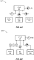
- the controller 204 may resolve conflicting determinations of presence or non-presence by three or more sensors via a simple majority "vote" of registering sensors. For example, if two sensors (210a, 210b) register non-presence (NP), and one sensor (106) registers presence (P), the visual presence sensor 106 may be outvoted and the controller 204 may determine that the operator is not present (NP).
- the controller 204 may resolve conflicting determinations from two or more sensors by assigning a weight to each registering sensor. For example, the controller 204 may assign a weight of 3 (PPP) to the visual presence sensor 106 and a weight of 1 (NP) to the seat-based pressure sensor 210a and harness sensor 210b, such that a scenario similar to that shown by FIG. 6A (visual presence sensor 106 registers presence P, seat-based pressure sensors 210a and harness sensor 210b register non-presence NP), is instead interpreted by the controller as a determination of presence (P) due to the greater weight assigned to the visual presence sensor.
- PPP weight of 3
- NP weight of 1
- the method 700 may be implemented by the OSS 200 and smart engagement/disengagement system 202 within a vehicle and may incorporate the following steps.
- the OSS determines its operational state as engaged or disengaged, e.g., monitoring or not monitoring a pilot or co-pilot.
- one or more presence sensors of the OSS determine a presence of non-presence of an operator in a control area of the vehicle, and register the determination of presence or non-presence with the smart engagement/disengagement system.
- visual presence sensors may determine whether a pilot or co-pilot is seated in a pilot seat/co-pilot seat within an aircraft cockpit.
- seat-based sensors may determine whether the operator is present or not present in the pilot seat/co-pilot seat.
- the OSS may prompt the operator to engage or disengage the OSS. For example, if the operator is present and the OSS is disengaged, the OSS will prompt the operator to re-engage; similarly, if the operator is not present and the OSS is engaged, the OSS will prompt the pilot (directly or remotely) to disengage the OSS. If multiple sensors register presence or non-presence, the OSS will resolve any conflicting determinations via majority vote of the registering sensors, or via assigning different weights or priorities to different sensors.
- embodiments of the methods disclosed herein may include one or more of the steps described herein. Further, such steps may be carried out in any desired order and two or more of the steps may be carried out simultaneously with one another. Two or more of the steps disclosed herein may be combined in a single step, and in some embodiments, one or more of the steps may be carried out as two or more sub-steps. Further, other steps or sub-steps may be carried in addition to, or as substitutes to one or more of the steps disclosed herein.
Landscapes
- Engineering & Computer Science (AREA)
- Aviation & Aerospace Engineering (AREA)
- Physics & Mathematics (AREA)
- General Physics & Mathematics (AREA)
- Seats For Vehicles (AREA)
Abstract
Description
- The present application is related to and claims priority to
U.S. Provisional Patent Application Serial No. 63/196,854 filed June 4, 2021 - Modern cockpits may be equipped with physiological monitoring systems capable of tracking various health or well-being related states of a pilot or co-pilot; e.g., fatigue/alertness, heart rate, oxygenation, G-force strain. Such physiological monitors can be very valuable for tracking pilot capability inflight, but they may also introduce extra workload and procedures that must be incorporated into the pilot's routine. For example, when the pilot leaves their seat (or, e.g., the cockpit), the monitoring system must be disengaged lest the system conclude from any associated changes in state that an event has occurred requiring emergency intervention. Similarly, when the pilot returns to their seat the monitoring system must be re-engaged.
- In a first aspect, an operator safety system (OSS) for monitoring the well-being of a vehicle operator or pilot in a cockpit of control area of the vehicle is disclosed. In embodiments, the OSS includes presence sensors within the control area for assessing whether or not the operator is currently present, e.g., seated in the appropriate pilot or co-pilot seat. An operator interface includes a display surface viewable by the operator and an input device for accepting control input. The OSS may be either engaged (e.g., actively monitoring the operator or pilot) or disengaged; the operator interface allows the operator to either engage or disengage the device (e.g., when the operator enters or leaves the pilot/co-pilot seat). When the presence sensors determine that the operator is no longer present (e.g., having left the pilot seat or the cockpit) but the OSS is still in an engaged state, the OSS prompts the operator to disengage the OSS via the interface. Similarly, when the presence sensors determine that the operator is present but the OSS is disengaged, the OSS prompts the operator to re-engage the OSS.
- In some embodiments, the display surface and the input device are combined in an interactive touchscreen, such that the operator can engage or disengage the OSS via a single-touch interaction (e.g., when prompted to do so).
- In some embodiments, the presence sensors include cameras or other like image sensors oriented toward the pilot/co-pilot seat.
- In some embodiments, the cameras are configured for thermal imaging (e.g., in the infrared band) of the pilot seat and/or cockpit. For example, the OSS determines a heat level of the pilot seat/control area and determines the presence or non-presence of the operator based on the detected heat.
- In some embodiments, the OSS determines, based on a detected residual heat level, approximately how long the operator has been absent from the pilot seat.
- In some embodiments, the cameras detect encoded fiducial markers in the pilot seat or cockpit, and determines the presence or non-presence of the operator based on whether the fiducial markers can be detected and decoded (e.g., as the presence of the operator may obstruct some or all fiducial markers).
- In some embodiments, the vehicle is an aircraft, the operator is a pilot or co-pilot (seated in a pilot seat or co-pilot seat respectively), and the presence sensors determine whether or not the pilot/co-pilot is seated in the appropriate seat.
- In some embodiments, the presence sensors are embedded within the pilot/co-pilot seat, and the OSS determines the presence or non-presence of the operator based on pressure and/or temperature (e.g., body heat) detected within the pilot/co-pilot seat.
- In some embodiments, the presence sensors are located within, or connected to, a safety belt or safety harness securing the operator to the pilot/co-pilot seat, The safety belt or harness may be fastened or unfastened, the fastened or unfastened state detectable by the presence sensors to indicate operator presence or non-presence.
- In some embodiments, e.g., if the operator is not present either in the pilot seat or within the control area/cockpit, the OSS prompts the operator to disengage remotely, e.g., via a mobile device carried by the operator, and via which the operator can remotely disengage the OSS.
- In some embodiments, the OSS is connected to a flight management system (FMS) or other like vehicle control system, and assesses the presence or non-presence of the operator in response to a demand issued by the FMS, e.g., based on a triggering event.
- In some embodiments, the presence sensors include at least two independent sensors (or banks/groups thereof) that independently register a determination of operator presence or non-presence. The OSS will determine the ultimate presence or non-presence of the operator based on a majority of registered decisions from the independent sensors.
- In some embodiments, the OSS assigns a weight to each independent sensor or bank thereof, and determines the presence or non-presence of the operator based on a weighted majority of registered decisions from the independent sensors.
- In a further aspect, a method for smart monitoring of a vehicle operator is also disclosed. In embodiments, the method includes determining a current operational status (engaged or disengaged) of a vehicle-based operator safety system (OSS) for monitoring physiological parameters of an operator of the vehicle. The method includes determining, via presence sensors in communication with the OSS, whether the operator is currently present or not present in a control area of the vehicle. The method includes, based on the determined presence or non-presence of the operator and the engaged or disengaged status of the OSS, prompting the operator to adjust the operational status of the OSS. For example, the vehicle may be an aircraft of which the operator is a pilot or co-pilot, and the method includes assessing whether or not the operator is currently seated in the appropriate pilot or co-pilot seat within the cockpit.
- In some embodiments, the method includes, when the OSS is engaged but the operator is not present, prompting the operator (remotely if necessary) to disengage the OSS.
- In some embodiments, the method includes, when the OSS is disengaged but the operator is present, prompting the operator to engage (or re-engage) the OSS.
- In some embodiments, the method includes independently assessing the presence or non-presence of the operator via at least two independent sensors or banks/groups thereof, and determining the presence or non-presence of the operator based on a majority of independently registered determinations or presence or non-presence.
- In some embodiments, the method includes assigning, via the OSS, a weight to each independent presence sensor or bank thereof, and determining the presence or non-presence of the operator based on a weighted majority of determinations of presence or non-presence independently registered by the sensors.
- This Summary is provided solely as an introduction to subject matter that is fully described in the Detailed Description and Drawings. The Summary should not be considered to describe essential features nor be used to determine the scope of the Claims. Moreover, it is to be understood that both the foregoing Summary and the following Detailed Description are example and explanatory only and are not necessarily restrictive of the subject matter claimed.
- The detailed description is described with reference to the accompanying figures. The use of the same reference numbers in different instances in the description and the figures may indicate similar or identical items. Various embodiments or examples ("examples") of the present disclosure are disclosed in the following detailed description and the accompanying drawings. The drawings are not necessarily to scale. In general, operations of disclosed processes may be performed in an arbitrary order, unless otherwise provided in the claims. In the drawings:
-
FIG. 1 is a control area of a vehicle according to example embodiments of this disclosure; -
FIG. 2 is a block diagram illustrating an operator safety system (OSS: e.g., pilot safety system (PSS)) according to example embodiments of this disclosure; -
FIG. 3 is an illustration of an operator seat incorporating presence sensors of the OSS ofFIG. 2 ; -
FIGS. 4A and 4B are illustrations of thermal presence sensors of the OSS ofFIG. 2 ; -
FIG. 5 is an illustration of an operator seat incorporating encoded markers compatible with the OSS ofFIG. 2 ; -
FIGS. 6A and 6B are block diagrams illustrating the OSS ofFIG. 2 incorporating multiple deconflicting presence sensors; - and
FIG. 7 is a process flow diagram illustrating a method for smart monitoring of a vehicle operator according to example embodiments of this disclosure. - Before explaining one or more embodiments of the disclosure in detail, it is to be understood that the embodiments are not limited in their application to the details of construction and the arrangement of the components or steps or methodologies set forth in the following description or illustrated in the drawings. In the following detailed description of embodiments, numerous specific details may be set forth in order to provide a more thorough understanding of the disclosure. However, it will be apparent to one of ordinary skill in the art having the benefit of the instant disclosure that the embodiments disclosed herein may be practiced without some of these specific details. In other instances, well-known features may not be described in detail to avoid unnecessarily complicating the instant disclosure.
- As used herein a letter following a reference numeral is intended to reference an embodiment of the feature or element that may be similar, but not necessarily identical, to a previously described element or feature bearing the same reference numeral (e.g., 1, 1a, 1b). Such shorthand notations are used for purposes of convenience only and should not be construed to limit the disclosure in any way unless expressly stated to the contrary.
- Further, unless expressly stated to the contrary, "or" refers to an inclusive or and not to an exclusive or. For example, a condition A or B is satisfied by any one of the following: A is true (or present) and B is false (or not present), A is false (or not present) and B is true (or present), and both A and B are true (or present).
- In addition, use of "a" or "an" may be employed to describe elements and components of embodiments disclosed herein. This is done merely for convenience and "a" and "an" are intended to include "one" or "at least one," and the singular also includes the plural unless it is obvious that it is meant otherwise.
- Finally, as used herein any reference to "one embodiment" or "some embodiments" means that a particular element, feature, structure, or characteristic described in connection with the embodiment is included in at least one embodiment disclosed herein. The appearances of the phrase "in some embodiments" in various places in the specification are not necessarily all referring to the same embodiment, and embodiments may include one or more of the features expressly described or inherently present herein, or any combination or sub-combination of two or more such features, along with any other features which may not necessarily be expressly described or inherently present in the instant disclosure.
- Referring to
FIG. 1 , acontrol space 100 of a vehicle is shown. Thecontrol space 100 may includepilot seat 102,co-pilot seat 104, andpresence sensor 106. - In embodiments, the vehicle may include an aircraft, of which the
control space 100 is a cockpit configured to accommodate a pilot and co-pilot respectively thepilot seat 102 and theco-pilot seat 104. Thecontrol space 100 may include an operator safety system (OSS), e.g., a pilot monitoring system for assessing the physiological well-being of the pilot and/or co-pilot inflight. For example, the OSS may continually assess heart rate, breathing, eye movement, blood flow or oxygenation, and other vital statistics to anticipate or avoid unexplained physiological events (UPE) such as hypoxia, hypercapnia (excessive levels of CO2 in the blood), G-force strain, or other like symptoms indicative of potential pilot fatigue or impairment. - In embodiments, the OSS may require the pilot or co-pilot manually disengage the system when leaving the
pilot seat 102 orco-pilot seat 104. For example, the pilot may temporarily leave thecontrol space 100, designating the co-pilot as the pilot flying. Should the pilot or co-pilot fail to manually disengage the OSS, the resulting changes in state associated with the pilot or co-pilot's absence may be interpreted by the OSS as an emergency requiring intervention. Similarly, should the pilot or co-pilot return to their respective seat without manually re-engaging the OSS, the data detected and reported by the OSS may be compromised; further, a disengaged OSS may fail to detect subsequent pilot well-being issues. - Referring to
FIG. 2 , theOSS 200 is disclosed. TheOSS 200 may include a smart engagement/disengagement system 202 comprising acontroller 204,interface 206, memory 208, and seat-basedpresence sensors 210. - In embodiments, the smart engagement/
disengagement system 202 may determine whether an operator of a vehicle (e.g., an operator monitored by the OSS 200) is present in thecontrol space 100. If the presence or non-presence of the pilot or co-pilot is inconsistent with the current engagement status of theOSS 200, the OSS may prompt the pilot or co-pilot to manually adjust the engagement status of the OSS to align with their presence or non-presence in thecontrol space 100. For example, if thecontrol space 100 is an aircraft cockpit, the smart engagement/disengagement system 202 may continually determine (e.g., at a predetermined time interval) whether the pilot is present in thepilot seat 102 and/or whether the co-pilot is present in theco-pilot seat 104. - In embodiments, the smart engagement/
disengagement system 202 may be accessible via theinterface 206, including adisplay 206a for presenting information related to the OSS (e.g., alerts, data, engagement status) and aninput device 206b for accepting control input from the pilot. For example, theinterface 206 may be embodied in a touchscreen surface (e.g., a fixed cockpit display or a mobile computing device in wired or wireless communication with the OSS 200). For example, when the smart engagement/disengagement system 202 determines that the presence or non-presence of the pilot is inconsistent with the engagement status of theOSS 200, thedisplay 206a may present a notification requesting the pilot disengage or re-engage the OSS, e.g., via a single-touch engagement with theinput device 206b. Alternatively, or additionally, thecontroller 204 may prompt the pilot via a mobile device 212 (e.g., a smartphone or other like portable computing or communications device) carried on the pilot's person and in wireless communication with theOSS 200. For example, if the pilot has left thecontrol space 100, the pilot may still be prompted (e.g., viadisplay 212a) to disengage (e.g., viamobile device input 212b) the OSS. - In embodiments, if the smart engagement/
disengagement system 202 determines the pilot to be not present, e.g., not seated in thepilot seat 102, and theOSS 200 is still engaged, thecontroller 204 may prompt the pilot to disengage the OSS. For example, if the pilot has left thepilot seat 102 but has not yet left thecontrol space 100, thecontroller 204 may prompt the pilot to disengage theOSS 200 before leaving. Similarly, if the smart engagement/disengagement system 202 determines the pilot to be present, e.g., having returned to thepilot seat 102, and theOSS 200 is still disengaged, thecontroller 204 may similarly prompt the pilot to re-engage the OSS. - In embodiments, the smart engagement/
disengagement system 202 may determine the presence or non-presence of the pilot or co-pilot via one or more presence sensors, e.g., including (but not limited to)visual presence sensors 106 and/or seat-basedpresence sensors 210. For example, thevisual presence sensors 106 may include a camera or other like image sensor configured to capture image data for analysis by thecontroller 204. In embodiments, thevisual presence sensors 106 may be oriented toward the pilot seat 102 (e.g., or co-pilot seat 104) with an unobstructed view of the pilot seat/co-pilot seat (or, e.g., the pilot or co-pilot, when present in either seat). - In embodiments, the
controller 204 may include one or more processors configured to analyze image data captured by thevisual presence sensors 106 to determine (e.g., to a sufficient level of confidence) whether the pilot is present or not present in the pilot seat 102 (or, e.g., the co-pilot within the co-pilot seat). For example, thecontroller 204 may perform a coarse analysis of the image data, e.g., to determine whether or not the image data portray anempty pilot seat 102 or an occupied pilot seat, whether the image data indicate movement from frame to frame, and/or whether the image data indicate contrast with the pilot seat itself (e.g., a dark mass contrasting with a light-colored pilot seat, indicative of a uniformed pilot occupying the pilot seat). Alternatively, or additionally, thecontroller 204 may perform a fine analysis of the image data to determine not merely whether thepilot seat 102/co-pilot seat 104 is occupied or not, but whether an occupied pilot seat is occupied by a uniformed pilot, by a specific pilot-in-command or co-pilot authorized for access to thecontrol space 100, or by an individual not authorized for access to the control space. For example, the controller may compare the image data to reference images of uniformed pilots (e.g., which may include the authorized pilot, co-pilot, or other cockpit crew members) to more positively identify an occupant of thepilot seat 102 orco-pilot seat 104. - In embodiments, the seat-based
presence sensors 210 may be disposed or embedded within thepilot seat 102 and/orco-pilot seat 104 and may be configured to detect whether the said seat is currently occupied or not occupied (equivalent to a determination of a pilot/co-pilot as present-not present). For example, the seat-basedpresence sensors 210 may detect changes in pressure and/or temperature within thepilot seat 102/co-pilot seat 104 and thereby determine, to a level of confidence, that the said pilot seat/co-pilot seat currently has a human occupant, informing thecontroller 204 that the said pilot seat/co-pilot seat is currently occupied or not occupied. - In embodiments, the smart engagement/
disengagement system 202 may be in communication with a vehicle management system (e.g., flight management system 214 (FMS; e.g., flight control system)) of the vehicle or aircraft. For example, above and beyond periodic checks for pilot/co-pilot presence/non-presence, theFMS 214 may initiate a detection of the pilot/co-pilot in response to one or more triggering events; e.g., an inflight emergency or multiple unsuccessful attempts to contact the pilot on the part of air traffic control (ATC). - Referring now to
FIG. 3 , thepilot seat 102 is shown. In embodiments, the co-pilot seat (104,FIG. 2 ) may be implemented similarly to the pilot seats 102 shown byFIGS. 3, 4A, 4B, and 5 . - In embodiments, the
pilot seat 102 may incorporate multiple seat-based presence sensors (210,FIG. 2 ) operating independently of each other and reporting to the controller (204,FIG. 2 ). For example, thepilot seat 102 may incorporate seat-basedpressure sensors 210a embedded within aseat cushion 302 of the pilot seat (or within a seatpan or seat frame component). In embodiments, the seat-basedpressure sensors 210a may register the pressure or weight of a human occupant of the pilot seat 102 (e.g., seated upon the seat cushion 302) and may accordingly determine (and register with the controller 204) that an operator is present in the pilot seat. Similarly, if normal pressure or weight is detected by the seat-basedpressure sensors 210a (e.g., consistent with an empty seat), the seat-based pressure sensors may determine and register that an operator is not present. - In some embodiments, seat-based
presence sensors 210 may include aharness sensor 210b disposed or embedded within a seatbelt 304 (e.g., within a buckle) or safety harness configured for securing the operator to thepilot seat 102, the harness sensor capable of determining whether the seatbelt/harness is fastened or unfastened. For example, theseatbelt 304 may be fastened or unfastened; if the seatbelt is unfastened, theharness sensor 210b may determine and register that the operator is not present. Similarly, if theseatbelt 304 is fastened, theharness sensor 210b may determine and report that the operator is present. - Referring now to
FIGS. 4A and 4B , in embodiments the visual presence sensors (106,FIG. 2 ) may include image sensors or cameras operating in non-visible spectra (e.g., forward-looking infrared (FLIR) sensors). For example, thevisual presence sensors 106 may include thermal imagers oriented at thepilot seat 102. Thermal imagers may detect temperature readings orheat signatures 402 associated with thepilot seat 102 indicative of the body heat of a human occupant, and may therefore determine and register that an operator is present in the pilot seat. Similarly, if the thermal imagers fail to detect sufficient heat to indicate a current human occupant, thevisual presence sensors 106 may determine and register that an operator is not present. - The
visual presence sensors 106 may include thermal imagers capable (in collaboration with the controller 204) of detecting additional information associated with a non-present operator in thepilot seat 102. In embodiments, referring in particular toFIG. 4B , the thermal imagers may detectresidual heat signatures 404 associated with the pilot seat. While theresidual heat signatures 404 may not be indicative of a current human occupant, thecontroller 204 may infer, based on the heat levels detected and reported by the thermal imagers, not only that an operator is not currently present in thepilot seat 102, but the duration since the operator left the pilot seat. For example, based on the inferred duration, thecontroller 204 may determine whether to prompt the operator to disengage the OSS (200,FIG. 2 ) via the interface (206,FIG. 2 ) or via mobile device (212,FIG. 2 ), e.g., if the duration suggests the operator may have left the control space (100,FIG. 1 ). - Referring in particular to
FIG. 5 , thepilot seat 102 may incorporate encodedfiducials 502 set into the upholstery of theseatback 504 and/orseat cushion 302 and oriented toward thevisual presence sensors 106. In embodiments, thevisual presence sensors 106 may determine whether an operator is present in thepilot seat 102 based on an ability or inability to detect and decode the encodedfiducials 502. For example, if the encodedfiducials 502 are detected and decoded by thevisual presence sensors 106, thecontroller 204 may determine that an operator is not present in thepilot seat 102. Similarly, if thevisual presence sensors 106 are unable to detect the encodedfiducials 502, thecontroller 204 may infer that an operator is present. - Referring to
FIG. 6A , the smart engagement/disengagement system 202 is shown. - In embodiments, the smart engagement/
disengagement system 202 may incorporate multiple and diverse presence sensors operating independently of each other to determine whether an operator or pilot is present or not present in the pilot seat/co-pilot seat (102/104,FIG. 2 ). For example, thecontroller 204 may receive determinations of presence or non-presence registered by visual presence sensors 106 (e.g., camera), seat-basedpressure sensors 210a, andharness sensor 210b. - In some embodiments, the determinations received by the
controller 204 may contradict each other. For example, the seat-basedpressure sensors 210a andharness sensor 210b may both register non-presence (NP). However, thevisual presence sensors 106 may detect movement (e.g., behind or in front of thepilot seat 102, indicative of an operator who may not be in the pilot seat but may remain within the control space (100,FIG. 1 ) and may therefore register a determination that an operator is present (P). - In some embodiments, the
controller 204 may resolve conflicting determinations of presence or non-presence by three or more sensors via a simple majority "vote" of registering sensors. For example, if two sensors (210a, 210b) register non-presence (NP), and one sensor (106) registers presence (P), thevisual presence sensor 106 may be outvoted and thecontroller 204 may determine that the operator is not present (NP). - In some embodiments, referring in particular to
FIG. 6B , thecontroller 204 may resolve conflicting determinations from two or more sensors by assigning a weight to each registering sensor. For example, thecontroller 204 may assign a weight of 3 (PPP) to thevisual presence sensor 106 and a weight of 1 (NP) to the seat-basedpressure sensor 210a andharness sensor 210b, such that a scenario similar to that shown byFIG. 6A (visual presence sensor 106 registers presence P, seat-basedpressure sensors 210a andharness sensor 210b register non-presence NP), is instead interpreted by the controller as a determination of presence (P) due to the greater weight assigned to the visual presence sensor. - Referring to
FIG. 7 , themethod 700 may be implemented by theOSS 200 and smart engagement/disengagement system 202 within a vehicle and may incorporate the following steps. - At a
step 702, the OSS determines its operational state as engaged or disengaged, e.g., monitoring or not monitoring a pilot or co-pilot. - At a
step 704, one or more presence sensors of the OSS determine a presence of non-presence of an operator in a control area of the vehicle, and register the determination of presence or non-presence with the smart engagement/disengagement system. For example, visual presence sensors may determine whether a pilot or co-pilot is seated in a pilot seat/co-pilot seat within an aircraft cockpit. Similarly, seat-based sensors may determine whether the operator is present or not present in the pilot seat/co-pilot seat. - At a
step 706, based on the registered determinations of presence or non-presence and the current operational state of the OSS, the OSS may prompt the operator to engage or disengage the OSS. For example, if the operator is present and the OSS is disengaged, the OSS will prompt the operator to re-engage; similarly, if the operator is not present and the OSS is engaged, the OSS will prompt the pilot (directly or remotely) to disengage the OSS. If multiple sensors register presence or non-presence, the OSS will resolve any conflicting determinations via majority vote of the registering sensors, or via assigning different weights or priorities to different sensors. - It is to be understood that embodiments of the methods disclosed herein may include one or more of the steps described herein. Further, such steps may be carried out in any desired order and two or more of the steps may be carried out simultaneously with one another. Two or more of the steps disclosed herein may be combined in a single step, and in some embodiments, one or more of the steps may be carried out as two or more sub-steps. Further, other steps or sub-steps may be carried in addition to, or as substitutes to one or more of the steps disclosed herein.
- Although inventive concepts have been described with reference to the embodiments illustrated in the attached drawing figures, equivalents may be employed and substitutions made herein without departing from the scope of the claims. Components illustrated and described herein are merely examples of a system/device and components that may be used to implement embodiments of the inventive concepts and may be replaced with other devices and components without departing from the scope of the claims. Furthermore, any dimensions, degrees, and/or numerical ranges provided herein are to be understood as non-limiting examples unless otherwise specified in the claims.
Claims (15)
- An operator safety system, OSS (200), for a vehicle, comprising:one or more presence sensors (106) configured for installation in a control area (100) of a vehicle, the one or more presence sensors (106,210a,210b) configured to determine a presence or non-presence of the operator in the control area;
andan operator interface comprising:at least one display surface (206a) configured to present information to the operator;
andat least one input device (206b) configured to accept control input from the operator;the OSS having an operational state selected from engaged or disengaged, the operator capable of transitioning the OSS between the engaged and disengaged states via the input device;the OSS configured:when the one or more presence sensors determine the operator is not present in the control area and the OSS state is engaged, to prompt the operator to disengage the OSS via the input device;
andwhen the one or more presence sensors determine the operator is present in the control area and the OSS state is disengaged, to prompt the operator to engage the OSS via the input device. - The operator safety system of Claim 1, wherein:the display surface and the input device are embodied in at least one touch-sensitive display screen (206a);and whereinthe input device (206b) is configured to allow the operator to engage or disengage the PSS via a single touch.
- The operator safety system of Claim 1 or 2, wherein the one or more presence sensors include at least one of a camera or an image sensor (106).
- The operator safety system of Claim 3, wherein:the one or more presence sensors are configured for thermal imaging of one or more of the operator or the control area;
andwherein the OSS is configured to:detect a heat level associated with the control area based on the thermal imaging;
anddetermine a presence or non-presence of the operator based on the detected heat level. - The operator safety system of Claim 4, wherein the OSS is configured to determine, based on the detected heat level:a non-presence of the operator;
anda duration associated with the non-presence of the operator. - The operator safety system of any preceding Claim, wherein:the one or more presence sensors are configured to detect encoded information associated with the control area;
and whereinthe OSS is configured to determine a presence or non-presence of the operator based on the detection of the encoded information. - The operator safety system of any preceding Claim, wherein:the vehicle is an aircraft;the operator is a pilot or a co-pilot of the aircraft;the control area includes a pilot seat (102);
andthe at least one presence sensor is configured to determine whether the operator is seated in a pilot seat; and optionally wherein:the one or more presence sensors are disposed within the pilot seat;
and whereinthe OSS is configured to determine whether the operator is seated in the pilot seat via at least one of a detected temperature or a detected pressure associated with the pilot seat. - The operator safety system of Claim 7, wherein:the one or more presence sensors are in communication with at least one of a safety belt or a safety harness configured to secure the operator to the pilot seat, the safety belt or safety harness having a fastened state and an unfastened state detectable by the one or more presence sensors;
and whereinthe OSS is configured to determine a presence or non-presence of the operator based on the fastened or unfastened state. - The operator safety system of any preceding Claim, wherein the OSS is configured to prompt the operator via a mobile device wirelessly linked to the OSS, the mobile device carried by the operator.
- The operator safety system of any preceding Claim, wherein the OSS is configured to periodically determine the presence or non-presence of the operator in the control area at a predetermined time interval.
- The operator safety system of any preceding Claim, wherein:the OSS is in communication with a vehicle management system (214);
andthe OSS is configured to determine the presence or non-presence of the operator in response to a triggering event received from the vehicle management system. - The operator safety system of any preceding Claim, wherein:the one or more presence sensors include at least two independent presence sensors, each independent presence sensor configured to register a decision that the operator is present or non-present;
and whereinthe OSS is configured to determine the presence or non-presence of the operator based on a majority of the one or more registered decisions; and optionally wherein the OSS is configured to:the OSS is configured to assign a weight to each registered decision;
anddetermine the presence of non-presence of the operator based on a weighted majority of the one or more registered decisions. - A method (700) for smart monitoring of a vehicle operator, the method comprising:determining (702), via a vehicle-based operator safety system (OSS) configured to measure one or more physiological parameters associated with an operator of a vehicle, a current operational status of the OSS, the operational state selected from an engaged state or a disengaged state;determining (704), via one or more presence sensors of the OSS, a presence or non-presence of the operator in a control area of the vehicle;
andbased on the determined presence or non-presence and the current operational state, prompting (706) the operator to adjust the operational status of the OSS. - The method of Claim 13, wherein based on the determined presence or non-presence and the current operational state, prompting the operator to adjust the operational status of the OSS includes:based on a determined presence of the operator in the control area and a current disengaged state of the OSS, prompting the operator to engage the OSS; and/orbased on a determined non-presence of the operator in the control area and a current engaged state of the OSS, prompting the operator to disengage the OSS.
- The method of Claim 13 or 14, wherein determining, via one or more presence sensors of the OSS, a presence or non-presence of the operator in a control area of the vehicle includes:independently assessing, via at least two independent presence sensors of the OSS, a presence or non-presence of the operator;registering with a controller of the OSS a presence or non-presence of the operator independently assessed by each independent presence sensor;
anddetermining, via the controller, the presence or non-presence based on a majority of registered assessments received from the at least two independent presence sensors; and optionally wherein determining, via one or more presence sensors of the OSS, a presence or non-presence of the operator in a control area of the vehicle includes:assigning, via the controller, a weight to each independent presence sensor;
and whereindetermining, via the controller, the presence or non-presence based on a majority of registered assessments received from the at least two independent presence sensors includes determining the presence or non-presence based on a majority of weighted registered assessments.
Applications Claiming Priority (2)
| Application Number | Priority Date | Filing Date | Title |
|---|---|---|---|
| US202163196854P | 2021-06-04 | 2021-06-04 | |
| US17/734,710 US20220388677A1 (en) | 2021-06-04 | 2022-05-02 | Vehicle operator monitoring system with smart active engagement and disengagement |
Publications (1)
| Publication Number | Publication Date |
|---|---|
| EP4101771A1 true EP4101771A1 (en) | 2022-12-14 |
Family
ID=82214383
Family Applications (1)
| Application Number | Title | Priority Date | Filing Date |
|---|---|---|---|
| EP22176964.9A Pending EP4101771A1 (en) | 2021-06-04 | 2022-06-02 | Vehicle operator monitoring system with smart active engagement and disengagement |
Country Status (2)
| Country | Link |
|---|---|
| US (1) | US20220388677A1 (en) |
| EP (1) | EP4101771A1 (en) |
Citations (3)
| Publication number | Priority date | Publication date | Assignee | Title |
|---|---|---|---|---|
| US6658572B1 (en) * | 2001-10-31 | 2003-12-02 | Secure Sky Ventures International Llc | Airline cockpit security system |
| US20190090800A1 (en) * | 2017-09-22 | 2019-03-28 | Aurora Flight Sciences Corporation | Systems and Methods for Monitoring Pilot Health |
| EP3556657A1 (en) * | 2018-04-18 | 2019-10-23 | The Boeing Company | Seat assembly, seatbelt security system, and method |
Family Cites Families (7)
| Publication number | Priority date | Publication date | Assignee | Title |
|---|---|---|---|---|
| US20080036581A1 (en) * | 2006-08-08 | 2008-02-14 | Bunims Jeffrey M | Seatbelt Adaptor |
| US9311794B2 (en) * | 2011-05-30 | 2016-04-12 | Pietro De Ieso | System and method for infrared intruder detection |
| US9823656B1 (en) * | 2016-06-29 | 2017-11-21 | Wipro Limited | Method and system for automatically performing safety operations to prevent crash of an airborne vehicle |
| US10773591B2 (en) * | 2016-10-17 | 2020-09-15 | FLIR Belgium BVBA | Video analytics based pilot safety devices |
| US10360797B2 (en) * | 2017-01-27 | 2019-07-23 | Qualcomm Incorporated | Request-response-based sharing of sensor information |
| US10220857B2 (en) * | 2017-02-23 | 2019-03-05 | Uber Technologies, Inc. | Vehicle control system |
| US20190369615A1 (en) * | 2018-06-05 | 2019-12-05 | Facultad Politecnica-Universidad Nacional del Este | System and method for verifying the presence and vital signs of pilots in a cockpit of an airplane |
-
2022
- 2022-05-02 US US17/734,710 patent/US20220388677A1/en active Pending
- 2022-06-02 EP EP22176964.9A patent/EP4101771A1/en active Pending
Patent Citations (3)
| Publication number | Priority date | Publication date | Assignee | Title |
|---|---|---|---|---|
| US6658572B1 (en) * | 2001-10-31 | 2003-12-02 | Secure Sky Ventures International Llc | Airline cockpit security system |
| US20190090800A1 (en) * | 2017-09-22 | 2019-03-28 | Aurora Flight Sciences Corporation | Systems and Methods for Monitoring Pilot Health |
| EP3556657A1 (en) * | 2018-04-18 | 2019-10-23 | The Boeing Company | Seat assembly, seatbelt security system, and method |
Also Published As
| Publication number | Publication date |
|---|---|
| US20220388677A1 (en) | 2022-12-08 |
Similar Documents
| Publication | Publication Date | Title |
|---|---|---|
| DE102006042299B4 (en) | Conditional warning and reporting system for an aircraft cabin to determine the cabin status | |
| EP3141483B1 (en) | Aircraft occupant health, safety, and comfort management | |
| US6963292B1 (en) | System and method for reporting emergencies from an aircraft | |
| CN102233858B (en) | For detecting the method that there is situation of occupant in seat | |
| US7783081B2 (en) | Method and device for verification of identity aboard an aircraft | |
| EP3495275B1 (en) | Integrated imaging system for a connected aircraft | |
| US8005595B2 (en) | Occupant monitoring and restraint status system | |
| WO2008036539A1 (en) | Passenger seats | |
| DE102006030193A1 (en) | System for determining aircraft seat state has seat monitoring device that provides information about state of seat with sensor element for measuring physical data; device determines seat state information from physical data | |
| US10881357B1 (en) | Systems and methods for monitoring the health of vehicle passengers using camera images | |
| EP3141482B1 (en) | Aircraft occupant seat for aircraft occupant health, safety, and comfort management | |
| CA3032317A1 (en) | Monitoring module for a seat of a passenger aircraft, monitoring device and passenger aircraft | |
| JP6816531B2 (en) | Crew monitoring device | |
| CN110386101B (en) | Seat assembly, safety belt safety system and method | |
| US20180208318A1 (en) | Safety belt, notably for aircraft seat | |
| EP4029739B1 (en) | Safety apparatus for indicating the usage state of a seat belt | |
| JP2007521171A (en) | Aircraft security apparatus, system and method | |
| JP2023093454A (en) | Abnormality detection device | |
| EP3872018B1 (en) | An elevator monitoring system | |
| WO2019107167A1 (en) | Image processing device, image processing system, image pickup device, image pickup system, and image processing method | |
| EP4101771A1 (en) | Vehicle operator monitoring system with smart active engagement and disengagement | |
| CN110891860A (en) | System for remotely monitoring an area intended to accommodate at least one passenger of an aircraft, and aircraft cabin equipped with such a remote monitoring system | |
| US20220048629A1 (en) | Seating System for a Passenger Aircraft, Method and Computer-Implementable Program Product | |
| KR101999103B1 (en) | System and method for providing vehicle safety service | |
| KR20140059678A (en) | Passenger friendly smart seats system based on piezoelectric elements |
Legal Events
| Date | Code | Title | Description |
|---|---|---|---|
| PUAI | Public reference made under article 153(3) epc to a published international application that has entered the european phase |
Free format text: ORIGINAL CODE: 0009012 |
|
| STAA | Information on the status of an ep patent application or granted ep patent |
Free format text: STATUS: THE APPLICATION HAS BEEN PUBLISHED |
|
| AK | Designated contracting states |
Kind code of ref document: A1 Designated state(s): AL AT BE BG CH CY CZ DE DK EE ES FI FR GB GR HR HU IE IS IT LI LT LU LV MC MK MT NL NO PL PT RO RS SE SI SK SM TR |
|
| STAA | Information on the status of an ep patent application or granted ep patent |
Free format text: STATUS: REQUEST FOR EXAMINATION WAS MADE |
|
| 17P | Request for examination filed |
Effective date: 20230612 |
|
| RBV | Designated contracting states (corrected) |
Designated state(s): AL AT BE BG CH CY CZ DE DK EE ES FI FR GB GR HR HU IE IS IT LI LT LU LV MC MK MT NL NO PL PT RO RS SE SI SK SM TR |
|
| GRAP | Despatch of communication of intention to grant a patent |
Free format text: ORIGINAL CODE: EPIDOSNIGR1 |
|
| STAA | Information on the status of an ep patent application or granted ep patent |
Free format text: STATUS: GRANT OF PATENT IS INTENDED |
|
| INTG | Intention to grant announced |
Effective date: 20240212 |
|
| RIN1 | Information on inventor provided before grant (corrected) |
Inventor name: MATESSA, MICHAEL P. Inventor name: WU, PEGGY Inventor name: JOHNSON, WADE T. Inventor name: WITTKOP, TIMOTHY J. Inventor name: RAO, ARJUN HARSHA Inventor name: GEORGE, CHRISTOPHER L. |