EP4092963B1 - Method and system for datacenter network device maintenance - Google Patents
Method and system for datacenter network device maintenance Download PDFInfo
- Publication number
- EP4092963B1 EP4092963B1 EP21305662.5A EP21305662A EP4092963B1 EP 4092963 B1 EP4092963 B1 EP 4092963B1 EP 21305662 A EP21305662 A EP 21305662A EP 4092963 B1 EP4092963 B1 EP 4092963B1
- Authority
- EP
- European Patent Office
- Prior art keywords
- network
- network devices
- datacenter
- clusters
- cluster
- Prior art date
- Legal status (The legal status is an assumption and is not a legal conclusion. Google has not performed a legal analysis and makes no representation as to the accuracy of the status listed.)
- Active
Links
- 238000012423 maintenance Methods 0.000 title claims description 57
- 238000000034 method Methods 0.000 title claims description 24
- 230000008520 organization Effects 0.000 claims description 10
- 230000001419 dependent effect Effects 0.000 claims description 3
- 238000005516 engineering process Methods 0.000 description 44
- 238000012986 modification Methods 0.000 description 5
- 230000004048 modification Effects 0.000 description 5
- 230000008569 process Effects 0.000 description 4
- 238000011161 development Methods 0.000 description 3
- 238000010586 diagram Methods 0.000 description 3
- 230000006870 function Effects 0.000 description 3
- 230000006855 networking Effects 0.000 description 3
- RYAUSSKQMZRMAI-YESZJQIVSA-N (S)-fenpropimorph Chemical compound C([C@@H](C)CC=1C=CC(=CC=1)C(C)(C)C)N1C[C@H](C)O[C@H](C)C1 RYAUSSKQMZRMAI-YESZJQIVSA-N 0.000 description 2
- 238000004590 computer program Methods 0.000 description 2
- 230000002776 aggregation Effects 0.000 description 1
- 238000004220 aggregation Methods 0.000 description 1
- 238000013459 approach Methods 0.000 description 1
- 238000004891 communication Methods 0.000 description 1
- 230000000694 effects Effects 0.000 description 1
- 238000012806 monitoring device Methods 0.000 description 1
- 238000010606 normalization Methods 0.000 description 1
- 238000012545 processing Methods 0.000 description 1
- 230000000644 propagated effect Effects 0.000 description 1
- 230000007704 transition Effects 0.000 description 1
Images


Classifications
-
- H—ELECTRICITY
- H04—ELECTRIC COMMUNICATION TECHNIQUE
- H04L—TRANSMISSION OF DIGITAL INFORMATION, e.g. TELEGRAPHIC COMMUNICATION
- H04L41/00—Arrangements for maintenance, administration or management of data switching networks, e.g. of packet switching networks
- H04L41/12—Discovery or management of network topologies
-
- H—ELECTRICITY
- H04—ELECTRIC COMMUNICATION TECHNIQUE
- H04L—TRANSMISSION OF DIGITAL INFORMATION, e.g. TELEGRAPHIC COMMUNICATION
- H04L41/00—Arrangements for maintenance, administration or management of data switching networks, e.g. of packet switching networks
- H04L41/08—Configuration management of networks or network elements
- H04L41/0803—Configuration setting
- H04L41/0813—Configuration setting characterised by the conditions triggering a change of settings
- H04L41/082—Configuration setting characterised by the conditions triggering a change of settings the condition being updates or upgrades of network functionality
-
- H—ELECTRICITY
- H04—ELECTRIC COMMUNICATION TECHNIQUE
- H04L—TRANSMISSION OF DIGITAL INFORMATION, e.g. TELEGRAPHIC COMMUNICATION
- H04L41/00—Arrangements for maintenance, administration or management of data switching networks, e.g. of packet switching networks
- H04L41/08—Configuration management of networks or network elements
- H04L41/0803—Configuration setting
- H04L41/0823—Configuration setting characterised by the purposes of a change of settings, e.g. optimising configuration for enhancing reliability
- H04L41/0836—Configuration setting characterised by the purposes of a change of settings, e.g. optimising configuration for enhancing reliability to enhance reliability, e.g. reduce downtime
-
- G—PHYSICS
- G06—COMPUTING; CALCULATING OR COUNTING
- G06F—ELECTRIC DIGITAL DATA PROCESSING
- G06F8/00—Arrangements for software engineering
- G06F8/60—Software deployment
- G06F8/65—Updates
-
- H—ELECTRICITY
- H04—ELECTRIC COMMUNICATION TECHNIQUE
- H04L—TRANSMISSION OF DIGITAL INFORMATION, e.g. TELEGRAPHIC COMMUNICATION
- H04L41/00—Arrangements for maintenance, administration or management of data switching networks, e.g. of packet switching networks
- H04L41/06—Management of faults, events, alarms or notifications
- H04L41/0654—Management of faults, events, alarms or notifications using network fault recovery
-
- H—ELECTRICITY
- H04—ELECTRIC COMMUNICATION TECHNIQUE
- H04L—TRANSMISSION OF DIGITAL INFORMATION, e.g. TELEGRAPHIC COMMUNICATION
- H04L41/00—Arrangements for maintenance, administration or management of data switching networks, e.g. of packet switching networks
- H04L41/08—Configuration management of networks or network elements
- H04L41/0866—Checking the configuration
-
- H—ELECTRICITY
- H04—ELECTRIC COMMUNICATION TECHNIQUE
- H04L—TRANSMISSION OF DIGITAL INFORMATION, e.g. TELEGRAPHIC COMMUNICATION
- H04L41/00—Arrangements for maintenance, administration or management of data switching networks, e.g. of packet switching networks
- H04L41/08—Configuration management of networks or network elements
- H04L41/0876—Aspects of the degree of configuration automation
- H04L41/0886—Fully automatic configuration
-
- H—ELECTRICITY
- H04—ELECTRIC COMMUNICATION TECHNIQUE
- H04L—TRANSMISSION OF DIGITAL INFORMATION, e.g. TELEGRAPHIC COMMUNICATION
- H04L41/00—Arrangements for maintenance, administration or management of data switching networks, e.g. of packet switching networks
- H04L41/08—Configuration management of networks or network elements
- H04L41/0893—Assignment of logical groups to network elements
-
- H—ELECTRICITY
- H04—ELECTRIC COMMUNICATION TECHNIQUE
- H04L—TRANSMISSION OF DIGITAL INFORMATION, e.g. TELEGRAPHIC COMMUNICATION
- H04L61/00—Network arrangements, protocols or services for addressing or naming
- H04L61/30—Managing network names, e.g. use of aliases or nicknames
Definitions
- the present technology relates to information technology, more particularly to a method and system for automated maintenance of network devices in a datacenter.
- a datacenter network may be composed of different architectures working side by side to offer connectivity and services, with each of those architectures having been designed with and for specific properties, hardware models, enabled features and/or levels of redundancy, and all those parallel architectures having been connected to a more central architecture or core network.
- the present technology aims at automating maintenance of network devices in a datacenter, by removing from automated maintenance those network devices with a higher risk of failed automated maintenance, and exploiting redundancy of the remaining network devices so as to limit downtime in the datacenter owing to maintenance operations.
- Embodiments of the present technology have been developed based on developers' appreciation of shortcomings associated with the prior art.
- the invention is defined in the independent claims. Particular embodiments are set out in the dependent claims.
- the present technology offers a method and system that will execute the exact same maintenance process when network devices conform to the same parameters (architecture, role, hardware model, running software release, and/or enabled features, etc.), so that risks of human error may be removed.
- An adjusted amount of parallel execution will limit the impact with unavailability of the datacenter.
- Disruption of the network connectivity services provided to clients will be minimized through identification of redundancy in the infrastructure of network devices that share certain parameters or characteristics, and non-simultaneous maintenance of such network devices, so as to possibly downgrade the service, yet not interrupt it entirely. Further, such method and system will allow the datacenter operator to easily account for new device hardware or new architectures between devices.
- a system may refer, but is not limited to, an "electronic device”, an “operation system”, a “computing system”, a “computer-based system”, a “controller unit”, a “monitoring device”, a “control device” and/or any combination thereof appropriate to the relevant task at hand.
- the functional steps shown in the figures may be provided through use of dedicated hardware, as well as hardware capable of executing software in association with appropriate software.
- the functions of the various functional blocks shown in the figures such as labeled « network device » « tool » « configurator » etc. may be provided through the use of dedicated hardware as well as hardware capable of executing software in association with appropriate software.
- the functions may be provided by a single dedicated processor, by a single shared processor, or by a plurality of individual processors, some of which may be shared.
- the processor may be a general purpose processor, such as a central processing unit (CPU) or a processor dedicated to a specific purpose, such as a digital signal processor (DSP).
- CPU central processing unit
- DSP digital signal processor
- explicit use of the term a « processor » should not be construed to refer exclusively to hardware capable of executing software, and may implicitly include, without limitation, application specific integrated circuit (ASIC), field programmable gate array (FPGA), read-only memory (ROM) for storing software, random access memory (RAM), and non-volatile storage.
- ASIC application specific integrated circuit
- FPGA field programmable gate array
- ROM read-only memory
- RAM random access memory
- non-volatile storage non-volatile storage.
- Tag is intended to represent a key-value tuple associated with each datacenter network device, and stored in a database, for example a Configuration Management Database (CMDB).
- CMDB Configuration Management Database
- the key uniquely identifies a data element, and the value is the actual data or a pointer to the data as the case may be.
- the Tag is an access key to certain characteristics of the datacenter network device.
- BU for Business Unit
- the business or product offering may be that of the organization that deploys, controls and maintains the infrastructure, or of its clients'.
- a BU may be server, cloud, hosting, etc. and depends on the granularity, diversity and complexity of a catalogue of business or product offerings.
- ROLE is intended to represent, as part of the Tag of a datacenter network device, a characteristic in relation to the place and function the datacenter network device occupies in the datacenter network infrastructure.
- ROLE may be without limitation: “aggregation”, “Top of Rack” (ToR), “End of Row” (EoR), “spine”, “megaspine” etc.
- IFRA is intended to represent, as part of the Tag of a datacenter network device, a characteristic in relation to the version or generation of the infrastructure, which may be evolving over time with enhancements and evolution, in which the datacenter network device is meant to operate.
- LOCATION is intended to represent, as part of information associated with a datacenter network device, a characteristic in relation to the actual physical location of the datacenter network device in the datacenter.
- LOCATION may be without limitation: the name of a datacenter building, a particular datacenter room, etc.
- MANAGEMENT IP is intended to represent, as part of information associated with a datacenter network device, a virtual identification, such as for example an IP address, uniquely associated with a datacenter network device, and allowing, through the use of for example an automation tool, to reach the datacenter network device and perform with it operations such as for example retrieving information, changing configuration, upgrading etc.
- a computer-readable medium and “the” computer-readable medium should not be construed as being the same computer-readable medium. To the contrary, and whenever appropriate, “a” computer-readable medium and “the” computer-readable medium may also be construed as a first computer-readable medium and a second computer-readable medium.
- Implementations of the present technology each have at least one of the above-mentioned object and/or aspects, but do not necessarily have all of them. It should be understood that some aspects of the present technology that have resulted from attempting to attain the above-mentioned object may not satisfy this object and/or may satisfy other objects not specifically recited herein.
- modules may be represented herein as any combination of flowchart elements or other elements indicating performance of process steps and/or textual description. Such modules may be executed by hardware that is expressly or implicitly shown. Moreover, it should be understood that module may include for example, but without being limitative, computer program logic, computer program instructions, software, stack, firmware, hardware circuitry or a combination thereof which provides the required capabilities.
- FIG. 1 depicts a datacenter environment in which the present technology may be used.
- a Network Upgrade Tool 100 provides a datacenter operator 101 with an input/output interface allowing it to enter inputs and options toward automation of a network device maintenance campaign, and receive status and results about such campaign.
- Network Upgrade Tool 100 may be developed using the YAQL language (Yet Another Query Language) and may be interpreted as workflows inside an open-source software orchestrator that is used to launch and organize tasks, subtasks and standalone actions.
- YAQL language Yet Another Query Language
- Network Upgrade Tool 100 may be part of a software stack 102 such as Mistral, which is one of the components of the OpenStack project: https://docs.openstack.org/mistral/latest/ . It will be apparent to the person skilled in the art that other language, software and software framework may be used still within the teachings of the present disclosure.
- Mistral is one of the components of the OpenStack project: https://docs.openstack.org/mistral/latest/ .
- Network Upgrade Tool 100 may further interface with a Network Configurator 105, as an abstractive and unified Application Programming Interface (API) system that gives the ability to interact with network devices in the datacenter, regardless of diversity of their hardware models or network operating systems.
- Network Configurator 105 may have an interface 106 with the datacenter network devices.
- Network Upgrade Tool 100 may further be coupled, and interface with a CMDB 103 that may reference network devices in the datacenter, and store for example Tags and MANAGEMENT IP in association with each of such referenced network devices, that Network Upgrade Tool 100 may retrieve. For example, upon deployment of each new network device in the datacenter, it may be given, for example by datacenter operator 101, a unique network device ID, and such network device ID may be used to retrieve from CMDB 103 the Tags and MANAGEMENT IP associated with the deployed network device.
- Network Upgrade Tool 100 may further interface with an Upgrade Path DB 104 that may reference network devices in the datacenter, and store in association with each of such referenced network devices, or groups of such network devices as the case may be, a path to a targeted network operating system level (ie: all necessary intermediate operating system levels between the current level, and the targeted level) that Network Upgrade Tool 100 may retrieve and use for the automated maintenance.
- an Upgrade Path DB 104 may reference network devices in the datacenter, and store in association with each of such referenced network devices, or groups of such network devices as the case may be, a path to a targeted network operating system level (ie: all necessary intermediate operating system levels between the current level, and the targeted level) that Network Upgrade Tool 100 may retrieve and use for the automated maintenance.
- Network Upgrade Tool 100 may further interface with a Rules DB 112 that may store rules that Network Upgrade Tool 100 may retrieve and use for the automated maintenance.
- Network Upgrade Tool 100 may check conformity of certain network devices with certain rules.
- rules may detail the expected redundancy of network devices in the datacenter sharing an identical INFRA Tag value.
- rules may be applicable to network devices sharing an identical combination of BU - ROLE - INFRA Tag values.
- CMDB 103 may, in all or in part, form part of the same physical and/or logical database, or be physically part of the Network Upgrade Tool 100, without affecting the generality of the teachings herein.
- Rules DB 112 may not even be a separate database, and rules may be hardcoded, for example in the Network Upgrade Tool 100.
- the datacenter may comprise a plurality of network devices 109 interconnected through connections 110 in an infrastructure as seen, merely as a simplified example, on Figure 1 .
- Each network device 109 may have associated with it, as part of its Tag(s):
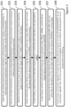
- FIG. 2 presents a broad overview of the method according to the present technology.
- certain parameters of network devices 109 to be maintained that may be present in a list of devices to be maintained) in the datacenter may be collected/fetched.
- step 203 may be removed from the maintenance list those network devices 109 with either hardware and software characteristics that are not supported (such as unsupported hardware model or current network operating system), ie that are not susceptible of automated maintenance by the present technology, or with an error with their BU, ROLE, INFRA Tag, or LOCATION information.
- their network operating system level may not be a supported level, or their hardware model may be outdated or unrecognized.
- their Tag(s) may not have a value recognized by the automated maintenance system of the present technology, or have (strictly) more or less than one single value for any of BU, ROLE, or INFRA Tag, etc.
- the remaining network devices 109 on the list may be clustered as follows:
- redundancy between network devices 109 may be identified. This redundancy may be defined at INFRA k level, in redundancy rules that the automated system of the present technology may apply to group redundant network devices 109 in Groups within each Cluster ijk .
- a Group may include 1 (no redundancy for this network device), or 2 or more network devices 109.
- conformity of the network devices 109 present in that Group may be checked with specific size rules applicable to the particular combination of BU; - ROLE j - INFRA k .
- a size rule may indicate that all Groups in a cluster Cluster ijk must include 3 network devices 109. All network devices 109 that belong to a Group that includes (strictly) more of less than 3 network devices 109 are non conform. Further, a check may be performed that all network devices 109 in the Group share the same LOCATION information.
- step 207 may be removed from the maintenance list those network devices 109 not having been clustered or grouped at steps 204 and 205, non-conformity to redundancy or size rules, or not sharing the same LOCATION information when present in the same Group, after steps 205 and 206.
- the automated process according to the present technology may upgrade successively all remaining network devices 109 in a Group. Since such network devices 109 are redundant ones, disruption to the functioning of the datacenter, and to the network connectivity service provided to clients of the organization that deploys, controls and maintains the datacenter, is minimized, and the technical unavailability of part or all of the datacenter owing to the maintenance of network devices is as limited as possible. The same may be performed for all created Groups in a Cluster ijk , and for all formed Clusters ijk clusters.
- Clusters ijk clusters adjusted to increase the speed of the maintenance process, while minimizing the overall downtime of the datacenter and disruption of the service to clients of the organization that deploys, controls and maintains the datacenter. Further, the order in which Clusters ijk clusters are handled may also be adjusted to optimize the continuation of services to clients of the organization.
- FIGS. 3a-3c provide a more detailed view of the method according to the present technology.
- fetching of the information of the level of current network operating system and of the hardware model may be attempted with network devices to be maintained in the datacenter. These network devices may be listed through a list of IDs on a Maintenance list.
- this may for example be performed by: (i) providing (by the datacenter operator 101 or otherwise) to Network Upgrade Tool 100 a Maintenance list of network device IDs, (ii) Network Upgrade Tool 100 collecting the corresponding MANAGEMENT IPs from CMDB 103, and (iii) Network Upgrade Tool 100 using the retrieved corresponding MANAGEMENT IPs to query the network devices to be maintained for information of the level of current network operating system and of the hardware model.
- the collecting/fetching is not necessarily successful, and IDs of network devices for which it was unsuccessful may be added to an Error list at steps 302 with 307 and be removed from the Maintenance list.
- a determination may be made, for remaining network devices on the Maintenance list (ie: those network devices for which the ID was not added to the Error list after steps 301/302), whether the hardware model fetched at step 301, is a supported one.
- "Supported hardware model” as used herein, means a hardware model that maintenance operations of the datacenter are capable of handling. Referring back to Figure 1 , this may for example be performed by: (i) storing (by the datacenter operator 101 or otherwise) in the Rules DB 112 the supported hardware models, (ii) Network Upgrade Tool 100 retrieving those supported hardware models from Rules DB 112, and (iii) Network Upgrade Tool 100 comparing the retrieved supported hardware models with the hardware models fetched at step 301. If the determination is unsuccessful or the hardware model is not a supported one, IDs of corresponding network devices may be added to the Error list at steps 304 with 307 and be removed from the Maintenance list.
- step 305 collecting of the information of the Tags, and LOCATION and MANAGEMENT IP information, may be attempted with remaining network devices on the Maintenance list to be maintained in the datacenter. This may be performed by the Network Upgrade Tool 100 collecting that information from CMDB 103. The collecting is not necessarily successful, and IDs of network devices for which it was unsuccessful may be added to the Error list at steps 306 with 307 and be removed from the Maintenance list.
- step 310 determination may be made, for remaining network devices on the Maintenance list, whether such network devices have one, and only one, value for Tags BU, ROLE and INFRA respectively (as fetched at step 305). IDs of network devices having no value in any of BU, ROLE or INFRA Tag, or more than one value, may be added to the Error list at steps 311 with 312, and be removed from the Maintenance list.
- remaining network devices on the Maintenance list may be grouped in clusters sharing the same BU Tag. IDs of network devices having a not known/recognized value in BU, may be added to the Error list at steps 314 with 312, and be removed from the Maintenance list.
- remaining network devices on the Maintenance list may be grouped, in each BU cluster, in sub-clusters sharing the same ROLE Tag. IDs of network devices having a not known/recognized value in ROLE, may be added to the Error list at steps 317 with 312, and be removed from the Maintenance list.
- FIG 4 provides a logical illustration of a clustering/sub-clustering of network devices in a datacenter according to steps 313 and 316 in Figure 3b .
- Only a portion of the datacenter network devices 401 is represented.
- Network devices 401 each possess a unique ID that has been illustrated as "NDxx”.
- network devices 401 have been clustered each in a BU cluster 402, illustrated as BU01 and BU11.
- network devices 401 have been sub-clustered each in a ROLE sub-cluster 403, illustrated as ROLE01, ROLE07, ROLE13, etc.
- network devices may further be grouped in sub-sub-clusters Cluster ijk that are sharing the same INFRA Tag k (INFRA k ).
- network devices that appear to be redundant in each Cluster ijk may further be grouped yet in Groups of redundant network devices.
- this may for example be performed by: (i) storing (by the datacenter operator 101 or otherwise) in the Rules DB 112 redundancy rules particular to INFRA k , (ii) Network Upgrade Tool 100 retrieving those redundancy rules from Rules DB 112, and (iii) Network Upgrade Tool 100 grouping network devices in Groups in each Cluster ijk according to those redundancy rules.
- the rules may for example be a normalization of IDs of network devices, that will inherently carry the redundancy information. For example, rules may be that IDs of redundant network devices in an INFRA k , end with the same chain of characters specific to that INFRA k .
- network devices present in each Group may be checked for their hardware model being one of one or several expected hardware models, according to rules applicable to the corresponding combination BU i - ROLE j - INFRA k .
- this may for example be performed by: (i) storing (by the datacenter operator 101 or otherwise) in the Rules DB 112 hardware model expectancy rules particular to BU i - ROLE j - INFRA k , (ii) Network Upgrade Tool 100 retrieving those hardware model expectancy rules from Rules DB 112, and (iii) Network Upgrade Tool 100 checking network devices in Groups in each Cluster ijk against those hardware model expectancy rules.
- the actual number of network devices present in each Group may be checked, according to size rules applicable to the corresponding combination BU i - ROLE j - INFRA k .
- this may for example be performed by: (i) storing (by the datacenter operator 101 or otherwise) in the Rules DB 112 size (number of network devices expectancy) rules particular to BU i - ROLE j - INFRA k , (ii) Network Upgrade Tool 100 retrieving those size rules from Rules DB 112, and (iii) Network Upgrade Tool 100 checking the number of network devices in Groups in each Cluster ijk against those size rules.
- step 324 it may be verified that all network devices present in each Group share the same LOCATION information. This LOCATION information was available to the Network Upgrade Tool 100 from step 305.
- the remaining network devices on the Maintenance list may be maintained: this is performed successively for all network devices in a Group, for all Cluster ijk .
- this may for example be performed by: (i) storing (by the datacenter operator 101 or otherwise) in the Upgrade Path DB 104 upgrade rules to take a network device from a current network operating system level to the targeted network operating system level, (ii) Network Upgrade Tool 100 retrieving those upgrade rules from Upgrade Path DB 104, and (iii) Network Upgrade Tool 100 applying the upgrades through Network Configurator 105.
- network devices involved in providing identical service to identical clients of the datacenter have been identified and grouped together, and maintenance has been performed successively through all network devices belonging in a group, after removal of those network devices that did not conform and for which automated maintenance is too risky.
- the service is not completely interrupted, merely downgraded as the case may.
- the granularity of the Error list referred to at steps 307, 312 and 326 may be higher, by keeping track of the cause for error.
- the Error list may be broken down in sub-lists allowing to distinguish between (i) errors that the datacenter operator 101 may be able to correct, such as Tags, classification, identification, and (ii) errors that are linked to a faulty network device such as through its network operating system level, etc.
- FIG. 5 illustrates a computing system that may be used in the present technology.
- An example of implementation of computing system 500 that may be used for the Network Upgrade Tool 100 and/or the Network Configurator 105 is presented.
- such computing system may be implemented in any other suitable hardware, software, and/or firmware, or a combination thereof, and may be a single physical entity, or several separate physical entities with a distributed functionality.
- the Computing System 500 may comprise various hardware components including one or more single or multi-core processors collectively represented by a processor 501, a solid-state drive 502, a memory 503 and an input/output interface 504.
- the processor 501 may or may not be included in a FPGA.
- the Computing System 500 may be an "off the shelf' generic computing system.
- the Computing System 500 may also be distributed amongst multiple systems.
- the Computing System 500 may also be specifically dedicated to the implementation of the present technology. As a person in the art of the present technology may appreciate, multiple variations as to how the Computing System 500 is implemented may be envisioned without departing from the scope of the present technology.
- Communication between the various components of the Computing System 500 may be enabled by one or more internal and/or external buses 505 (e.g. a PCI bus, universal serial bus, IEEE 1394 "Firewire” bus, SCSI bus, Serial-ATA bus, ARINC bus, etc.), to which the various hardware components are electronically coupled.
- internal and/or external buses 505 e.g. a PCI bus, universal serial bus, IEEE 1394 "Firewire” bus, SCSI bus, Serial-ATA bus, ARINC bus, etc.
- the input/output interface 504 may allow enabling networking capabilities such as wire or wireless access.
- the input/output interface 504 may comprise a networking interface such as, but not limited to, a network port, a network socket, a network interface controller and the like. Multiple examples of how the networking interface may be implemented will become apparent to the person skilled in the art of the present technology.
- the solid-state drive 502 may store program instructions, such as those part of, for example, a library, an application, etc. suitable for being loaded into the memory 503 and executed by the processor 501 for the method and process steps according to the present technology.
Landscapes
- Engineering & Computer Science (AREA)
- Computer Networks & Wireless Communication (AREA)
- Signal Processing (AREA)
- Software Systems (AREA)
- General Engineering & Computer Science (AREA)
- Theoretical Computer Science (AREA)
- Automation & Control Theory (AREA)
- Computer Security & Cryptography (AREA)
- Physics & Mathematics (AREA)
- General Physics & Mathematics (AREA)
- Data Exchanges In Wide-Area Networks (AREA)
Description
- The present technology relates to information technology, more particularly to a method and system for automated maintenance of network devices in a datacenter.
- Systems have been developed that purport to support maintenance of network devices, such as switches, routers, etc. in a datacenter. "Maintenance" as used herein, may include for example performing upgrade of devices from current to targeted (ex: up-to-date) network operating system. "Datacenter" as used herein, is not limited to the infrastructure located within physical boundaries of one server farm, but rather comprises all infrastructure, whether local or remote, that an organization deploys, controls and maintains to provide services based on computer clustering, to its own internal services, or to third party entities, altogether clients of the organization. Systems achieving automation of maintenance of network devices populating a datacenter while saving on the required manpower, avoiding human errors, and managing client impact, have been long in demand.
US Patent application N°2011/0321031 published December 29, 2011 , for example discloses a system for deploying an upgrade concurrently on a plurality of nodes propagated throughout a distributed computing platform. - Challenges to the development of such systems however have been, beyond the mere quantity of network devices to address, the diversity of such devices in the datacenter, including their properties and their role. For example, a datacenter network may be composed of different architectures working side by side to offer connectivity and services, with each of those architectures having been designed with and for specific properties, hardware models, enabled features and/or levels of redundancy, and all those parallel architectures having been connected to a more central architecture or core network.
- Challenges to such development have also been to minimize the disruption to the functioning of the datacenter, and to ensure that unavailability of part or all of the datacenter owing to the maintenance of network devices be as limited as possible. This allows in turn to minimize disruption in the network connectivity service provided to clients by the organization, meeting contractual quality of service commitments as the case may be.
- There is therefore a need for a method and system that allow a datacenter operator with no specific network knowledge to automate massive network device maintenance campaigns using a simple entry point, by providing a list of network devices to upgrade, and inputting some simple options if and when required.
- Generally speaking, the present technology aims at automating maintenance of network devices in a datacenter, by removing from automated maintenance those network devices with a higher risk of failed automated maintenance, and exploiting redundancy of the remaining network devices so as to limit downtime in the datacenter owing to maintenance operations.
- The subject matter discussed in the background section should not be assumed to be prior art merely as a result of its mention in the background section. Similarly, a problem mentioned in the background section or associated with the subject matter of the background section should not be assumed to have been previously recognized in the prior art. The subject matter in the background section merely represents different approaches.
- Embodiments of the present technology have been developed based on developers' appreciation of shortcomings associated with the prior art. The invention is defined in the independent claims. Particular embodiments are set out in the dependent claims.
- The present technology offers a method and system that will execute the exact same maintenance process when network devices conform to the same parameters (architecture, role, hardware model, running software release, and/or enabled features, etc.), so that risks of human error may be removed. An adjusted amount of parallel execution will limit the impact with unavailability of the datacenter. Disruption of the network connectivity services provided to clients will be minimized through identification of redundancy in the infrastructure of network devices that share certain parameters or characteristics, and non-simultaneous maintenance of such network devices, so as to possibly downgrade the service, yet not interrupt it entirely. Further, such method and system will allow the datacenter operator to easily account for new device hardware or new architectures between devices.
- In the context of the present description, unless expressly provided otherwise, a system, may refer, but is not limited to, an "electronic device", an "operation system", a "computing system", a "computer-based system", a "controller unit", a "monitoring device", a "control device" and/or any combination thereof appropriate to the relevant task at hand.
- In the context of the present description, the functional steps shown in the figures, may be provided through use of dedicated hardware, as well as hardware capable of executing software in association with appropriate software. Further, the functions of the various functional blocks shown in the figures, such as labeled « network device », « tool », « configurator », etc. may be provided through the use of dedicated hardware as well as hardware capable of executing software in association with appropriate software. When provided by a "processor", the functions may be provided by a single dedicated processor, by a single shared processor, or by a plurality of individual processors, some of which may be shared. In some embodiments of the present technology, the processor may be a general purpose processor, such as a central processing unit (CPU) or a processor dedicated to a specific purpose, such as a digital signal processor (DSP). In the aforementioned, explicit use of the term a « processor » should not be construed to refer exclusively to hardware capable of executing software, and may implicitly include, without limitation, application specific integrated circuit (ASIC), field programmable gate array (FPGA), read-only memory (ROM) for storing software, random access memory (RAM), and non-volatile storage. Other hardware, conventional and/or custom, may also be included.
- In the context of the present description, "Tag" is intended to represent a key-value tuple associated with each datacenter network device, and stored in a database, for example a Configuration Management Database (CMDB). The key uniquely identifies a data element, and the value is the actual data or a pointer to the data as the case may be. The Tag is an access key to certain characteristics of the datacenter network device.
- In the context of the present description, "BU" (for Business Unit) is intended to represent, as part of the Tag of a datacenter network device, a characteristic in relation to a business or product offering the datacenter network device is used for. The business or product offering may be that of the organization that deploys, controls and maintains the infrastructure, or of its clients'. For example, a BU may be server, cloud, hosting, etc. and depends on the granularity, diversity and complexity of a catalogue of business or product offerings.
- In the context of the present description, "ROLE" is intended to represent, as part of the Tag of a datacenter network device, a characteristic in relation to the place and function the datacenter network device occupies in the datacenter network infrastructure. For example ROLE may be without limitation: "aggregation", "Top of Rack" (ToR), "End of Row" (EoR), "spine", "megaspine" etc.
- In the context of the present description, "INFRA" is intended to represent, as part of the Tag of a datacenter network device, a characteristic in relation to the version or generation of the infrastructure, which may be evolving over time with enhancements and evolution, in which the datacenter network device is meant to operate.
- In the context of the present description, "LOCATION" is intended to represent, as part of information associated with a datacenter network device, a characteristic in relation to the actual physical location of the datacenter network device in the datacenter. For example LOCATION may be without limitation: the name of a datacenter building, a particular datacenter room, etc.
- In the context of the present description, "MANAGEMENT IP" is intended to represent, as part of information associated with a datacenter network device, a virtual identification, such as for example an IP address, uniquely associated with a datacenter network device, and allowing, through the use of for example an automation tool, to reach the datacenter network device and perform with it operations such as for example retrieving information, changing configuration, upgrading etc.
- Still in the context of the present description, "a" computer-readable medium and "the" computer-readable medium should not be construed as being the same computer-readable medium. To the contrary, and whenever appropriate, "a" computer-readable medium and "the" computer-readable medium may also be construed as a first computer-readable medium and a second computer-readable medium.
- Still in the context of the present description, unless expressly provided otherwise, the words "first", "second", "third", etc. have been used as adjectives only for the purpose of allowing for distinction between the nouns that they modify from one another, and not for the purpose of describing any particular relationship between those nouns.
- Implementations of the present technology each have at least one of the above-mentioned object and/or aspects, but do not necessarily have all of them. It should be understood that some aspects of the present technology that have resulted from attempting to attain the above-mentioned object may not satisfy this object and/or may satisfy other objects not specifically recited herein.
- Additional and/or alternative features, aspects and advantages of implementations of the present technology will become apparent from the following description, the accompanying drawings and the appended claims.
- For a better understanding of the present technology, as well as other aspects and further features thereof, reference is made to the following description which is to be used in conjunction with the accompanying drawings, where:
-
Figure 1 depicts a datacenter environment in which the present technology may be used; -
Figure 2 presents a broad overview of the method according to the present technology; -
Figures 3a-3c provide a more detailed view of the method according to the present technology; -
Figure 4 provides a logical illustration of a clustering/sub-clustering of network devices in a datacenter; and -
Figure 5 illustrates a computing system that may be used in the present technology. - It should be noted that, unless otherwise explicitly specified herein, the drawings are not to scale. Further, elements that are identical from one figure to the next share the same reference numerals.
- The examples and conditional language recited herein are principally intended to aid the reader in understanding the principles of the present technology and not to limit its scope to such specifically recited examples and conditions. It will be appreciated that those skilled in the art may devise various arrangements that, although not explicitly described or shown herein, nonetheless embody the principles of the present technology and are included within its spirit and scope.
- Furthermore, as an aid to understanding, the following description may describe relatively simplified implementations of the present technology. As persons skilled in the art would understand, various implementations of the present technology may be of a greater complexity.
- In some cases, what are believed to be helpful examples of modifications to the present technology may also be set forth. This is done merely as an aid to understanding, and, again, not to define the scope or set forth the bounds of the present technology. These modifications are not an exhaustive list, and a person skilled in the art may make other modifications while nonetheless remaining within the scope of the present technology. Further, where no examples of modifications have been set forth, it should not be interpreted that no modifications are possible and/or that what is described is the sole manner of implementing that element of the present technology.
- Moreover, all statements herein reciting principles, aspects, and implementations of the present technology, as well as specific examples thereof, are intended to encompass both structural and functional equivalents thereof, whether they are currently known or developed in the future. Thus, for example, it will be appreciated by those skilled in the art that any block diagrams herein represent conceptual views of illustrative circuitry embodying the principles of the present technology. Similarly, it will be appreciated that any flowcharts, flow diagrams, state transition diagrams, pseudo-code, and the like represent various processes that may be substantially represented in non-transitory computer-readable media and so executed by a computer or processor, whether or not such computer or processor is explicitly shown.
- Software modules, or simply modules which are implied to be software, may be represented herein as any combination of flowchart elements or other elements indicating performance of process steps and/or textual description. Such modules may be executed by hardware that is expressly or implicitly shown. Moreover, it should be understood that module may include for example, but without being limitative, computer program logic, computer program instructions, software, stack, firmware, hardware circuitry or a combination thereof which provides the required capabilities.
- With these fundamentals in place, we will now consider some non-limiting examples to illustrate various implementations of aspects of the present technology.
Figure 1 depicts a datacenter environment in which the present technology may be used. ANetwork Upgrade Tool 100 provides adatacenter operator 101 with an input/output interface allowing it to enter inputs and options toward automation of a network device maintenance campaign, and receive status and results about such campaign.Network Upgrade Tool 100 may be developed using the YAQL language (Yet Another Query Language) and may be interpreted as workflows inside an open-source software orchestrator that is used to launch and organize tasks, subtasks and standalone actions. For example,Network Upgrade Tool 100 may be part of asoftware stack 102 such as Mistral, which is one of the components of the OpenStack project: https://docs.openstack.org/mistral/latest/ . It will be apparent to the person skilled in the art that other language, software and software framework may be used still within the teachings of the present disclosure. -
Network Upgrade Tool 100 may further interface with aNetwork Configurator 105, as an abstractive and unified Application Programming Interface (API) system that gives the ability to interact with network devices in the datacenter, regardless of diversity of their hardware models or network operating systems.Network Configurator 105 may have aninterface 106 with the datacenter network devices. -
Network Upgrade Tool 100 may further be coupled, and interface with aCMDB 103 that may reference network devices in the datacenter, and store for example Tags and MANAGEMENT IP in association with each of such referenced network devices, thatNetwork Upgrade Tool 100 may retrieve. For example, upon deployment of each new network device in the datacenter, it may be given, for example bydatacenter operator 101, a unique network device ID, and such network device ID may be used to retrieve fromCMDB 103 the Tags and MANAGEMENT IP associated with the deployed network device. -
Network Upgrade Tool 100 may further interface with anUpgrade Path DB 104 that may reference network devices in the datacenter, and store in association with each of such referenced network devices, or groups of such network devices as the case may be, a path to a targeted network operating system level (ie: all necessary intermediate operating system levels between the current level, and the targeted level) thatNetwork Upgrade Tool 100 may retrieve and use for the automated maintenance. -
Network Upgrade Tool 100 may further interface with aRules DB 112 that may store rules thatNetwork Upgrade Tool 100 may retrieve and use for the automated maintenance. For example,Network Upgrade Tool 100 may check conformity of certain network devices with certain rules. For example, rules may detail the expected redundancy of network devices in the datacenter sharing an identical INFRA Tag value. For example other rules may be applicable to network devices sharing an identical combination of BU - ROLE - INFRA Tag values. - It will be appreciated by the person skilled in the art that, although represented as three separate physical and logical entities,
CMDB 103,Upgrade Path DB 104, andRules DB 112 may, in all or in part, form part of the same physical and/or logical database, or be physically part of theNetwork Upgrade Tool 100, without affecting the generality of the teachings herein. Also, depending on the corporate and development environment of the organization that deploys, controls and maintains the infrastructure,Rules DB 112 may not even be a separate database, and rules may be hardcoded, for example in theNetwork Upgrade Tool 100. - The datacenter may comprise a plurality of
network devices 109 interconnected throughconnections 110 in an infrastructure as seen, merely as a simplified example, onFigure 1 . Eachnetwork device 109 may have associated with it, as part of its Tag(s): - a ROLE;
- an
INFRA 111; and - a
BU 108. -
Figure 2 presents a broad overview of the method according to the present technology. Atsteps network devices 109 to be maintained (that may be present in a list of devices to be maintained) in the datacenter may be collected/fetched. This includes at step 201: the Tag or Tags associated with each one of thenetwork devices 109, including their BU, ROLE, INFRA, and their MANAGEMENT IP and LOCATION information. And this includes at step 202: fetching from thenetwork devices 109, using their corresponding MANAGEMENT IP information, certain parameters related to their hardware model, and their current network operating system. - At
step 203, may be removed from the maintenance list thosenetwork devices 109 with either hardware and software characteristics that are not supported (such as unsupported hardware model or current network operating system), ie that are not susceptible of automated maintenance by the present technology, or with an error with their BU, ROLE, INFRA Tag, or LOCATION information. For example, their network operating system level may not be a supported level, or their hardware model may be outdated or unrecognized. For example, their Tag(s) may not have a value recognized by the automated maintenance system of the present technology, or have (strictly) more or less than one single value for any of BU, ROLE, or INFRA Tag, etc. - At
step 204, the remainingnetwork devices 109 on the list may be clustered as follows: - forming i clusters BUi of
network devices 109 sharing the same BU Tag; - within each BUi cluster, forming j clusters ROLEj of
network devices 109 sharing the same ROLE Tag; - within each ROLEj cluster, forming k clusters Clusterijk, of
network devices 109 sharing the same INFRA Tag. - At
step 205, in each formed Clusterijk, redundancy betweennetwork devices 109 may be identified. This redundancy may be defined at INFRAk level, in redundancy rules that the automated system of the present technology may apply to groupredundant network devices 109 in Groups within each Clusterijk. A Group may include 1 (no redundancy for this network device), or 2 ormore network devices 109. - At
step 206, in each formed Group in a cluster Clusterijk, conformity of thenetwork devices 109 present in that Group, may be checked with specific size rules applicable to the particular combination of BU; - ROLEj - INFRAk. For example, a size rule may indicate that all Groups in a cluster Clusterijk must include 3network devices 109. Allnetwork devices 109 that belong to a Group that includes (strictly) more of less than 3network devices 109 are non conform. Further, a check may be performed that allnetwork devices 109 in the Group share the same LOCATION information. - At
step 207, may be removed from the maintenance list thosenetwork devices 109 not having been clustered or grouped atsteps steps - At
step 208, the automated process according to the present technology may upgrade successively all remainingnetwork devices 109 in a Group. Sincesuch network devices 109 are redundant ones, disruption to the functioning of the datacenter, and to the network connectivity service provided to clients of the organization that deploys, controls and maintains the datacenter, is minimized, and the technical unavailability of part or all of the datacenter owing to the maintenance of network devices is as limited as possible. The same may be performed for all created Groups in a Clusterijk, and for all formed Clustersijk clusters. The same may be performed in parallel for a number of Clustersijk clusters adjusted to increase the speed of the maintenance process, while minimizing the overall downtime of the datacenter and disruption of the service to clients of the organization that deploys, controls and maintains the datacenter. Further, the order in which Clustersijk clusters are handled may also be adjusted to optimize the continuation of services to clients of the organization. -
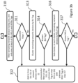
Figures 3a-3c provide a more detailed view of the method according to the present technology. Referring tofigure 3a , atstep 301, fetching of the information of the level of current network operating system and of the hardware model, may be attempted with network devices to be maintained in the datacenter. These network devices may be listed through a list of IDs on a Maintenance list. Referring back toFigure 1 , this may for example be performed by: (i) providing (by thedatacenter operator 101 or otherwise) to Network Upgrade Tool 100 a Maintenance list of network device IDs, (ii)Network Upgrade Tool 100 collecting the corresponding MANAGEMENT IPs fromCMDB 103, and (iii)Network Upgrade Tool 100 using the retrieved corresponding MANAGEMENT IPs to query the network devices to be maintained for information of the level of current network operating system and of the hardware model. The collecting/fetching is not necessarily successful, and IDs of network devices for which it was unsuccessful may be added to an Error list atsteps 302 with 307 and be removed from the Maintenance list. - At
step 303, a determination may be made, for remaining network devices on the Maintenance list (ie: those network devices for which the ID was not added to the Error list aftersteps 301/302), whether the hardware model fetched atstep 301, is a supported one. "Supported hardware model" as used herein, means a hardware model that maintenance operations of the datacenter are capable of handling. Referring back toFigure 1 , this may for example be performed by: (i) storing (by thedatacenter operator 101 or otherwise) in theRules DB 112 the supported hardware models, (ii)Network Upgrade Tool 100 retrieving those supported hardware models fromRules DB 112, and (iii)Network Upgrade Tool 100 comparing the retrieved supported hardware models with the hardware models fetched atstep 301. If the determination is unsuccessful or the hardware model is not a supported one, IDs of corresponding network devices may be added to the Error list atsteps 304 with 307 and be removed from the Maintenance list. - At
step 305, collecting of the information of the Tags, and LOCATION and MANAGEMENT IP information, may be attempted with remaining network devices on the Maintenance list to be maintained in the datacenter. This may be performed by theNetwork Upgrade Tool 100 collecting that information fromCMDB 103. The collecting is not necessarily successful, and IDs of network devices for which it was unsuccessful may be added to the Error list atsteps 306 with 307 and be removed from the Maintenance list. - Referring to
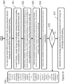
figure 3b , atstep 310, determination may be made, for remaining network devices on the Maintenance list, whether such network devices have one, and only one, value for Tags BU, ROLE and INFRA respectively (as fetched at step 305). IDs of network devices having no value in any of BU, ROLE or INFRA Tag, or more than one value, may be added to the Error list atsteps 311 with 312, and be removed from the Maintenance list. - At
step 313, remaining network devices on the Maintenance list may be grouped in clusters sharing the same BU Tag. IDs of network devices having a not known/recognized value in BU, may be added to the Error list atsteps 314 with 312, and be removed from the Maintenance list. - At
step 316, remaining network devices on the Maintenance list may be grouped, in each BU cluster, in sub-clusters sharing the same ROLE Tag. IDs of network devices having a not known/recognized value in ROLE, may be added to the Error list atsteps 317 with 312, and be removed from the Maintenance list. -
Figure 4 provides a logical illustration of a clustering/sub-clustering of network devices in a datacenter according tosteps Figure 3b . Only a portion of thedatacenter network devices 401 is represented.Network devices 401 each possess a unique ID that has been illustrated as "NDxx". As a result ofstep 313,network devices 401 have been clustered each in aBU cluster 402, illustrated as BU01 and BU11. As a result ofstep 316,network devices 401 have been sub-clustered each in aROLE sub-cluster 403, illustrated as ROLE01, ROLE07, ROLE13, etc. - Returning now to
Figure 3c , atstep 320, for each cluster BUi created atstep 313, and each sub-cluster ROLEj created atstep 316, network devices may further be grouped in sub-sub-clusters Clusterijk that are sharing the same INFRA Tag k (INFRAk). - At
step 321, network devices that appear to be redundant in each Clusterijk, according to redundancy rules applicable to the corresponding INFRAk, may further be grouped yet in Groups of redundant network devices. Referring back toFigure 1 , this may for example be performed by: (i) storing (by thedatacenter operator 101 or otherwise) in theRules DB 112 redundancy rules particular to INFRAk, (ii)Network Upgrade Tool 100 retrieving those redundancy rules fromRules DB 112, and (iii)Network Upgrade Tool 100 grouping network devices in Groups in each Clusterijk according to those redundancy rules. The rules may for example be a normalization of IDs of network devices, that will inherently carry the redundancy information. For example, rules may be that IDs of redundant network devices in an INFRAk, end with the same chain of characters specific to that INFRAk. - At
step 322, network devices present in each Group may be checked for their hardware model being one of one or several expected hardware models, according to rules applicable to the corresponding combination BUi - ROLEj - INFRAk. Referring back toFigure 1 , this may for example be performed by: (i) storing (by thedatacenter operator 101 or otherwise) in theRules DB 112 hardware model expectancy rules particular to BUi - ROLEj - INFRAk, (ii)Network Upgrade Tool 100 retrieving those hardware model expectancy rules fromRules DB 112, and (iii)Network Upgrade Tool 100 checking network devices in Groups in each Clusterijk against those hardware model expectancy rules. - At
step 323, the actual number of network devices present in each Group may be checked, according to size rules applicable to the corresponding combination BUi - ROLEj - INFRAk. Referring back toFigure 1 , this may for example be performed by: (i) storing (by thedatacenter operator 101 or otherwise) in theRules DB 112 size (number of network devices expectancy) rules particular to BUi - ROLEj - INFRAk, (ii)Network Upgrade Tool 100 retrieving those size rules fromRules DB 112, and (iii)Network Upgrade Tool 100 checking the number of network devices in Groups in each Clusterijk against those size rules. - At
step 324, it may be verified that all network devices present in each Group share the same LOCATION information. This LOCATION information was available to theNetwork Upgrade Tool 100 fromstep 305. - At
steps steps step 322, that were not totalling in a Group an expected number atstep 323, or that did not share the same LOCATION when in the same Group, may be added to the Error list, and be removed from the Maintenance list. - At
step 327, the remaining network devices on the Maintenance list may be maintained: this is performed successively for all network devices in a Group, for all Clusterijk. Referring back toFigure 1 , this may for example be performed by: (i) storing (by thedatacenter operator 101 or otherwise) in theUpgrade Path DB 104 upgrade rules to take a network device from a current network operating system level to the targeted network operating system level, (ii)Network Upgrade Tool 100 retrieving those upgrade rules fromUpgrade Path DB 104, and (iii)Network Upgrade Tool 100 applying the upgrades throughNetwork Configurator 105. - Through the present technology, network devices involved in providing identical service to identical clients of the datacenter have been identified and grouped together, and maintenance has been performed successively through all network devices belonging in a group, after removal of those network devices that did not conform and for which automated maintenance is too risky. Thus, the service is not completely interrupted, merely downgraded as the case may.
- The person skilled in the art will appreciate that the granularity of the Error list referred to at
steps datacenter operator 101 may be able to correct, such as Tags, classification, identification, and (ii) errors that are linked to a faulty network device such as through its network operating system level, etc. -
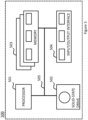
Figure 5 illustrates a computing system that may be used in the present technology. An example of implementation ofcomputing system 500 that may be used for theNetwork Upgrade Tool 100 and/or theNetwork Configurator 105 is presented. As will be appreciated by the person skilled in the art, such computing system may be implemented in any other suitable hardware, software, and/or firmware, or a combination thereof, and may be a single physical entity, or several separate physical entities with a distributed functionality. - In some aspects of the present technology, the
Computing System 500 may comprise various hardware components including one or more single or multi-core processors collectively represented by aprocessor 501, a solid-state drive 502, amemory 503 and an input/output interface 504. In this context, theprocessor 501 may or may not be included in a FPGA. In some other aspect, theComputing System 500 may be an "off the shelf' generic computing system. In some aspect, theComputing System 500 may also be distributed amongst multiple systems. TheComputing System 500 may also be specifically dedicated to the implementation of the present technology. As a person in the art of the present technology may appreciate, multiple variations as to how theComputing System 500 is implemented may be envisioned without departing from the scope of the present technology. - Communication between the various components of the
Computing System 500 may be enabled by one or more internal and/or external buses 505 (e.g. a PCI bus, universal serial bus, IEEE 1394 "Firewire" bus, SCSI bus, Serial-ATA bus, ARINC bus, etc.), to which the various hardware components are electronically coupled. - The input/
output interface 504 may allow enabling networking capabilities such as wire or wireless access. As an example, the input/output interface 504 may comprise a networking interface such as, but not limited to, a network port, a network socket, a network interface controller and the like. Multiple examples of how the networking interface may be implemented will become apparent to the person skilled in the art of the present technology. According to implementations of the present technology, the solid-state drive 502 may store program instructions, such as those part of, for example, a library, an application, etc. suitable for being loaded into thememory 503 and executed by theprocessor 501 for the method and process steps according to the present technology. - While the above-described implementations have been described and shown with reference to particular steps performed in a particular order, it will be understood that these steps may be combined, sub-divided, or re-ordered without departing from the teachings of the present disclosure. At least some of the steps may be executed in parallel or in series. Accordingly, the order and grouping of the steps is not a limitation of the present technology. It should further be expressly understood that not all technical effects mentioned herein need to be enjoyed in each and every embodiment of the present technology.
- The foregoing description is intended to be exemplary rather than limiting. The scope of the present technology is therefore intended to be limited solely by the scope of the appended claims.
Claims (15)
- A method for maintenance of network devices in a datacenter, comprising:- collecting (201) for each one of the network devices on a Maintenance list:- a virtual identification uniquely associated with the network device, MANAGEMENT IP;- an information representative of the actual physical location of the network device, LOCATION; and- key-value tuples associated with the network device, Tags, wherein the key is one of:- an information representative of a business or product offering the network device is used for in the datacenter, BU;- an information representative of a place and function the network device occupies in the datacenter, ROLE; and- an information representative a version or generation of the datacenter in which the network device operates, INFRA;and wherein the value is an actual data or pointer to the data for the key;- fetching (202) for each one of the network devices on the Maintenance list, using the respective MANAGEMENT IP, a hardware model and a current network operating system level of the network device;- removing (203) from the Maintenance list network devices with unsupported hardware model or current network operating system level, or with an error in any of their respective associated BU, ROLE, and INFRA Tags, or in any of their LOCATION;- clustering (204) the remaining network devices on the Maintenance list, in i clusters BUi of those network devices having the same value of BU key in one of their associated Tags, j clusters ROLEj within BUi clusters, of those network devices having the same value of ROLE key in one of their associated Tags, and k clusters Clusterijk within ROLEj clusters of those network devices having the same value of INFRA key in one of their associated Tags;- creating (205) within each Clusterijk cluster, Groups of network devices that are redundant, and:- verifying (205) that the number of redundant network devices in each created Group matches a first quantity applicable, according to redundancy rules, to INFRAk;- verifying (206) that the number of network devices in each created Group matches a second quantity applicable, according to size rules, to a combination BUi - ROLEj - INFRAk; and- verifying (206) that all network devices in each created Group share the same LOCATION;- removing (207) from the Maintenance list network devices present and redundant in a Group in a quantity that does not match the first quantity, present in a Group in a quantity that does not match the second quantity, or present in a Group and not sharing the same LOCATION; and- successively upgrading (208) , using upgrade rules and the respective MANAGEMENT IP, the remaining network devices in each created Group, for all Groups within all Clusterijk clusters, from the current version of network operating system to a targeted version of operating system.
- The method of claim 1, wherein the collecting and the fetching is performed using a unique ID assigned by a datacenter operator at deployment of the datacenter to each one of the network devices on the Maintenance list, and associated to any of its associated Tags, and MANAGEMENT IP and LOCATION.
- The method of claim 1 or 2, wherein the removing from the Maintenance list further comprises removing network devices not having exactly one value for each of BU, ROLE, and INFRA Tags.
- The method of claim 2, or 3 when dependent upon claim 2, wherein the removing from the Maintenance list further comprises creating an Error list populated with the unique IDs of removed network devices.
- The method of claim 4, wherein the Error list further comprises sub-lists for errors that may be corrected by the datacenter operator, and for errors linked to a faulty network device.
- The method of any of the claims 1 to 5, wherein the successively upgrading further comprises adjusting the number of Clusterijk clusters handled in parallel to minimize the downtime of the datacenter.
- The method of any of the claims 1 to 6, wherein the successively upgrading further comprises adjusting the order in which Clusterijk clusters are handled to optimize the continuation of services to clients of an organization that deploys, controls and maintains the datacenter.
- A system for maintenance of network devices in a datacenter, the system comprising a Network Upgrade Tool (100) coupled to a CMDB (103), a Rules DB (112), an upgrade Path DB (104) and a Network Configurator (105), the Network Upgrade Tool being configured to:- collect (201) from the CMDB for each one of the network devices on a Maintenance list:- a virtual identification uniquely associated with the network device, MANAGEMENT IP;- an information representative of the actual physical location of the network device, LOCATION; and- key-value tuples associated with the network device, Tags, wherein the key is one of:- an information representative of a business or product offering the network device is used for in the datacenter, BU;- an information representative of a place and function the network device occupies in the datacenter, ROLE; and- an information representative a version or generation of the datacenter in which the network device operates, INFRA;and wherein the value is an actual data or pointer to the data for the key;- fetch (202) for each one of the network devices on the Maintenance list, using the respective MANAGEMENT IP, a hardware model and a current network operating system level of the network device;- remove (203) from the Maintenance list network devices with unsupported hardware model or current network operating system level, or with an error in any of their respective associated BU, ROLE, and INFRA Tags, or in any of their LOCATION;- cluster (204) the remaining network devices on the Maintenance list, in i clusters BUi of those network devices having the same value of BU key in one of their associated Tags, j clusters ROLEj within BUi clusters, of those network devices having the same value of ROLE key in one of their associated Tags, and in k clusters Clusterijk within ROLEj clusters of those network devices having the same value of INFRA key in one of their associated Tags;- create (205) within each Clusterijk cluster, Groups of network devices that are redundant according to redundancy rules collected from the Rules DB applicable to INFRAk; and- verify (205) that the number of redundant network devices in each created Group matches a first quantity applicable, according to redundancy rules, to INFRAk;- verify (206) that the number of network devices in each created Group matches a second quantity applicable, according to size rules, to a combination BUi - ROLEj - INFRAk, and- verify (206) that all network devices in each created Group share the same LOCATION;- remove (207) from the Maintenance list network devices present and redundant in a Group in a quantity that does not match the first quantity, present in a Group in a quantity that does not match the second quantity, or present in a Group and not sharing the same LOCATION; and- successively upgrade (208), through the Network Configurator, using upgrade rules collected from the Upgrade Path DB and the respective MANAGEMENT IP, the remaining network devices in each created Group, for all Groups within all Clusterijk clusters, from the current version of network operating system to a targeted version of operating system.
- The system of claim 8, wherein the Network Upgrade Tool is further configured to collect and fetch using a unique ID assigned by a datacenter operator at deployment of the datacenter to each one of the network devices on the Maintenance list, and associated to any of its associated Tags, and MANAGEMENT IP and LOCATION.
- The system of claim 8 or 9 when dependent upon claim 8, wherein the Network Upgrade Tool is further configured to create an Error list populated with the unique IDs of network devices removed from the Maintenance list.
- The system of claim 10, wherein the Error list further comprises sub-lists for errors that may be corrected by the datacenter operator, and for errors linked to a faulty network device.
- The system of any of the claims 8 to 11, wherein the Network Upgrade Tool is further configured to adjust the number of Clusterijk clusters handled in parallel to minimize the downtime of the datacenter.
- The system of any of the claims 8 to 12, wherein the Network Upgrade Tool is further configured to adjust the order in which Clusterijk clusters are handled to optimize the continuation of services to clients of an organization that deploys, controls and maintains the datacenter.
- The system of any of the claims 8 to 13, wherein the redundancy and size rules are hardcoded in the Network Upgrade Tool.
- A computer-readable medium comprising instructions causing a computing system to perform the method of any of the claims 1 to 7.
Priority Applications (4)
| Application Number | Priority Date | Filing Date | Title |
|---|---|---|---|
| EP21305662.5A EP4092963B1 (en) | 2021-05-20 | 2021-05-20 | Method and system for datacenter network device maintenance |
| US17/748,002 US20220376985A1 (en) | 2021-05-20 | 2022-05-18 | Method and system for datacenter network device maintenance |
| CA3159474A CA3159474A1 (en) | 2021-05-20 | 2022-05-19 | Method and system for datacenter network device maintenance |
| CN202210553546.4A CN115378812A (en) | 2021-05-20 | 2022-05-20 | Method and system for data center network equipment maintenance |
Applications Claiming Priority (1)
| Application Number | Priority Date | Filing Date | Title |
|---|---|---|---|
| EP21305662.5A EP4092963B1 (en) | 2021-05-20 | 2021-05-20 | Method and system for datacenter network device maintenance |
Publications (2)
| Publication Number | Publication Date |
|---|---|
| EP4092963A1 EP4092963A1 (en) | 2022-11-23 |
| EP4092963B1 true EP4092963B1 (en) | 2024-05-08 |
Family
ID=76325461
Family Applications (1)
| Application Number | Title | Priority Date | Filing Date |
|---|---|---|---|
| EP21305662.5A Active EP4092963B1 (en) | 2021-05-20 | 2021-05-20 | Method and system for datacenter network device maintenance |
Country Status (4)
| Country | Link |
|---|---|
| US (1) | US20220376985A1 (en) |
| EP (1) | EP4092963B1 (en) |
| CN (1) | CN115378812A (en) |
| CA (1) | CA3159474A1 (en) |
Families Citing this family (1)
| Publication number | Priority date | Publication date | Assignee | Title |
|---|---|---|---|---|
| CN116684303B (en) * | 2023-08-01 | 2023-10-27 | 聪育智能科技(苏州)有限公司 | Digital twinning-based data center operation and maintenance method and system |
Family Cites Families (35)
| Publication number | Priority date | Publication date | Assignee | Title |
|---|---|---|---|---|
| US8346897B2 (en) * | 2008-02-25 | 2013-01-01 | Jon Jaroker | System and method for deploying and maintaining software applications |
| US8407689B2 (en) * | 2010-06-25 | 2013-03-26 | Microsoft Corporation | Updating nodes considering service model constraints |
| US20120102543A1 (en) * | 2010-10-26 | 2012-04-26 | 360 GRC, Inc. | Audit Management System |
| US10326645B2 (en) * | 2011-11-11 | 2019-06-18 | Level 3 Communications, Llc | System and methods for configuration management |
| US8935375B2 (en) * | 2011-12-12 | 2015-01-13 | Microsoft Corporation | Increasing availability of stateful applications |
| US9201933B2 (en) * | 2014-04-01 | 2015-12-01 | BizDox, LLC | Systems and methods for documenting, analyzing, and supporting information technology infrastructure |
| US10044795B2 (en) * | 2014-07-11 | 2018-08-07 | Vmware Inc. | Methods and apparatus for rack deployments for virtual computing environments |
| US9893940B1 (en) * | 2015-05-26 | 2018-02-13 | Amazon Technologies, Inc. | Topologically aware network device configuration |
| EP3395010B1 (en) * | 2015-12-26 | 2020-08-26 | Intel Corporation | Distributed framework for resilient machine-to-machine system management |
| AU2017207319B2 (en) * | 2016-01-11 | 2018-05-24 | Equinix, Inc. | Architecture for data center infrastructure monitoring |
| US10089178B2 (en) * | 2016-02-29 | 2018-10-02 | International Business Machines Corporation | Developing an accurate dispersed storage network memory performance model through training |
| US11941279B2 (en) * | 2017-03-10 | 2024-03-26 | Pure Storage, Inc. | Data path virtualization |
| US10498608B2 (en) * | 2017-06-16 | 2019-12-03 | Cisco Technology, Inc. | Topology explorer |
| US10862749B1 (en) * | 2017-07-21 | 2020-12-08 | Vmware, Inc. | Systems for and methods of network management and verification using intent inference |
| US11089113B2 (en) * | 2017-08-07 | 2021-08-10 | Citrix Systems, Inc. | Systems and methods to retain existing connections so that there is no connection loss when nodes are added to a cluster for capacity or when a node is taken out from the cluster for maintenance |
| US11082296B2 (en) * | 2017-10-27 | 2021-08-03 | Palo Alto Networks, Inc. | IoT device grouping and labeling |
| US10338913B2 (en) * | 2017-12-05 | 2019-07-02 | Archemy, Inc. | Active adaptation of networked compute devices using vetted reusable software components |
| US10698674B2 (en) * | 2018-02-06 | 2020-06-30 | Smartshift Technologies, Inc. | Systems and methods for entry point-based code analysis and transformation |
| US10740075B2 (en) * | 2018-02-06 | 2020-08-11 | Smartshift Technologies, Inc. | Systems and methods for code clustering analysis and transformation |
| US10528343B2 (en) * | 2018-02-06 | 2020-01-07 | Smartshift Technologies, Inc. | Systems and methods for code analysis heat map interfaces |
| WO2020010503A1 (en) * | 2018-07-10 | 2020-01-16 | 深圳花儿数据技术有限公司 | Multi-layer consistent hashing-based distributed data storage method and system |
| US10742501B1 (en) * | 2018-12-21 | 2020-08-11 | Juniper Networks, Inc. | Automation of maintenance mode operations for network devices |
| US10938660B1 (en) * | 2018-12-21 | 2021-03-02 | Juniper Networks, Inc. | Automation of maintenance mode operations for network devices |
| US10958517B2 (en) * | 2019-02-15 | 2021-03-23 | At&T Intellectual Property I, L.P. | Conflict-free change deployment |
| CA3130892A1 (en) * | 2019-02-20 | 2020-08-27 | Level 3 Communications, Llc | Systems and methods for communications node upgrade and selection |
| US11799888B2 (en) * | 2019-06-07 | 2023-10-24 | Hewlett Packard Enterprise Development Lp | Automatic identification of roles and connection anomalies |
| US20210012239A1 (en) * | 2019-07-12 | 2021-01-14 | Microsoft Technology Licensing, Llc | Automated generation of machine learning models for network evaluation |
| US10996938B2 (en) * | 2019-07-15 | 2021-05-04 | Juniper Networks, Inc. | Automated selection of software images for network devices |
| US11290332B2 (en) * | 2019-12-11 | 2022-03-29 | Oracle International Corporation | System and method for modelling cloud networks for automation |
| EP3926891B1 (en) * | 2020-06-19 | 2024-05-08 | Accenture Global Solutions Limited | Intelligent network operation platform for network fault mitigation |
| US20210405902A1 (en) * | 2020-06-30 | 2021-12-30 | Portworx, Inc. | Rule-based provisioning for heterogeneous distributed systems |
| US11520673B2 (en) * | 2020-07-21 | 2022-12-06 | Hewlett Packard Enterprise Development Lp | Maintenance operations based on analysis of collected data |
| US20220057947A1 (en) * | 2020-08-20 | 2022-02-24 | Portworx, Inc. | Application aware provisioning for distributed systems |
| US20220239648A1 (en) * | 2020-10-16 | 2022-07-28 | Somos, Inc. | Systems and methods for an internet of things device registry display |
| US20220335165A1 (en) * | 2021-04-16 | 2022-10-20 | Somos, Inc. | Systems and methods for provisioning virtual internet of things universal ids (iot uids) in green devices |
-
2021
- 2021-05-20 EP EP21305662.5A patent/EP4092963B1/en active Active
-
2022
- 2022-05-18 US US17/748,002 patent/US20220376985A1/en active Pending
- 2022-05-19 CA CA3159474A patent/CA3159474A1/en active Pending
- 2022-05-20 CN CN202210553546.4A patent/CN115378812A/en active Pending
Also Published As
| Publication number | Publication date |
|---|---|
| CN115378812A (en) | 2022-11-22 |
| EP4092963A1 (en) | 2022-11-23 |
| CA3159474A1 (en) | 2022-11-20 |
| US20220376985A1 (en) | 2022-11-24 |
Similar Documents
| Publication | Publication Date | Title |
|---|---|---|
| US11657256B2 (en) | Datacenter level utilization prediction without operating system involvement | |
| US9354961B2 (en) | Method and system for supporting event root cause analysis | |
| US9960963B2 (en) | Dynamic client fail-over during a rolling patch installation based on temporal server conditions | |
| US10091138B2 (en) | In service upgrades for a hypervisor or hardware manager hosting virtual traffic managers | |
| US8438253B2 (en) | Upgrading network traffic management devices while maintaining availability | |
| EP3182280A1 (en) | Machine for development of analytical models | |
| AU2016259298A1 (en) | Machine for development and deployment of analytical models | |
| US20120054756A1 (en) | Dynamic Test Scheduling | |
| CN109885316A (en) | Hdfs-hbase dispositions method and device based on kubernetes | |
| CN106789327A (en) | The automatic method and system that host is added for cloud platform | |
| US20210218798A1 (en) | Intelligent distribution of virtual network function images | |
| EP3588290A1 (en) | Resources management in internet of robotic things (iort) environments | |
| CN111752637B (en) | Multi-service inspection management method and device, computer equipment and storage medium | |
| US20220376985A1 (en) | Method and system for datacenter network device maintenance | |
| CN108737499A (en) | server configuration method and device | |
| US9098392B1 (en) | Systems and methods for changing fencing modes in clusters | |
| US10163060B2 (en) | Hierarchical probability model generation system, hierarchical probability model generation method, and program | |
| WO2021003677A1 (en) | Service upgrade method and apparatus in distributed system, and distributed system | |
| US10511487B2 (en) | Method and mechanism for efficiently managing flows | |
| WO2020036749A1 (en) | Modular system framework for software network function automation | |
| CN115632944A (en) | Node configuration method, device, equipment, readable storage medium and server | |
| KR102344992B1 (en) | Systems and methods for centralization of server initialization information | |
| CN112448842A (en) | Method and system for pushing new rack into data center to enter operation mode | |
| US20240154875A1 (en) | Network system construction device, communication system, network system construction method, and non-transitory computer-readable medium | |
| US20240143413A1 (en) | Managing edge compute servers with a data center element manager |
Legal Events
| Date | Code | Title | Description |
|---|---|---|---|
| PUAI | Public reference made under article 153(3) epc to a published international application that has entered the european phase |
Free format text: ORIGINAL CODE: 0009012 |
|
| STAA | Information on the status of an ep patent application or granted ep patent |
Free format text: STATUS: REQUEST FOR EXAMINATION WAS MADE |
|
| 17P | Request for examination filed |
Effective date: 20211021 |
|
| AK | Designated contracting states |
Kind code of ref document: A1 Designated state(s): AL AT BE BG CH CY CZ DE DK EE ES FI FR GB GR HR HU IE IS IT LI LT LU LV MC MK MT NL NO PL PT RO RS SE SI SK SM TR |
|
| REG | Reference to a national code |
Ref document number: 602021013023 Country of ref document: DE Ref country code: DE Ref legal event code: R079 Free format text: PREVIOUS MAIN CLASS: H04L0012240000 Ipc: H04L0041082000 |
|
| GRAP | Despatch of communication of intention to grant a patent |
Free format text: ORIGINAL CODE: EPIDOSNIGR1 |
|
| STAA | Information on the status of an ep patent application or granted ep patent |
Free format text: STATUS: GRANT OF PATENT IS INTENDED |
|
| RIC1 | Information provided on ipc code assigned before grant |
Ipc: H04L 41/0893 20220101ALI20240206BHEP Ipc: H04L 41/082 20220101AFI20240206BHEP |
|
| GRAS | Grant fee paid |
Free format text: ORIGINAL CODE: EPIDOSNIGR3 |
|
| INTG | Intention to grant announced |
Effective date: 20240306 |
|
| GRAA | (expected) grant |
Free format text: ORIGINAL CODE: 0009210 |
|
| STAA | Information on the status of an ep patent application or granted ep patent |
Free format text: STATUS: THE PATENT HAS BEEN GRANTED |
|
| AK | Designated contracting states |
Kind code of ref document: B1 Designated state(s): AL AT BE BG CH CY CZ DE DK EE ES FI FR GB GR HR HU IE IS IT LI LT LU LV MC MK MT NL NO PL PT RO RS SE SI SK SM TR |
|
| REG | Reference to a national code |
Ref country code: GB Ref legal event code: FG4D |
|
| REG | Reference to a national code |
Ref country code: CH Ref legal event code: EP |